OPERATOR’S MANUAL
FLEX CONNECT™
POLE SAW ATTACHMENT
STC459
To Reduce The Risk Of Injury, User Must Read
CAUTION
And Understand Operator’s Manual. Save These Instructions For
Future Reference.
2901894ME
267-2152

TABLE OF CONTENTS
Safety Symbols ........................................................................................................... Page 2
Safety Instructions ...................................................................................................... Page 3
Overview ..................................................................................................................... Page 7
Specications...................................................................................................................
Page 7
Assembly .................................................................................................................... Page 9
Operation .................................................................................................................. Page 11
Maintenance ............................................................................................................. Page 12
Troubleshooting ........................................................................................................ Page 15
Exploded View........................................................................................
...........
............Page 16
Notes ........................................................................................................................ Page 17
Warranty ................................................................................................................... Page 18
Page 2
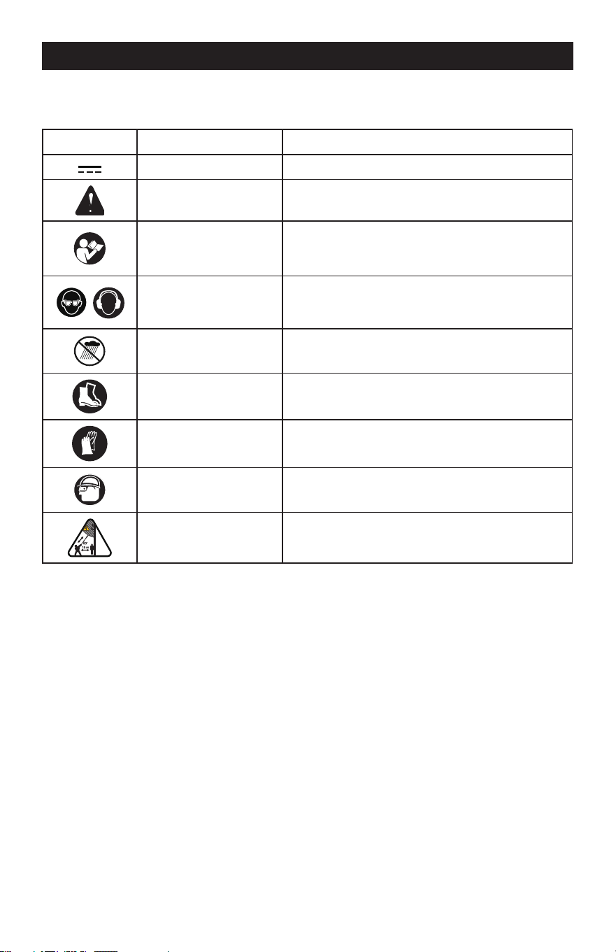
SAFETY SYMBOLS
Some of the following symbols may be used on this product. Please study them and learn their
meaning. Proper interpretation of these symbols will allow you to operate the product better
and safer.
Symbol Name Designation / Explanation
Direct Current Type or a characteristic of current
Safety Alert Symbol
Precautions that involve your safety.
Read the Instruction
Manual
To reduce the risk of injury, user must read and
understand the Instruction manual before using
this product.
Wear eye and ear
protection.
Wear eye and ear protection when operating this
equipment.
Wet Conditions Alert Do not expose to rain or use in damp locations.
Safety Footwear
Wear non-slip safety footwear when using this
equipment.
Gloves
Wear non-slip, heavy-duty protective gloves when
handling the chainsaw and the blade.
Head Protection
Wear head protection when operating this
equipment
Risk of Electrocution DANGER! Risk of electrocution!
Page 3
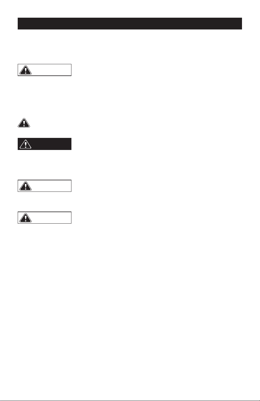
SAFETY INSTRUCTIONS
The purpose of safety symbols is to attract our attention to possible dangers. The safety
symbols, and the explanations with them, deserve your careful attention and understanding.
The symbol warnings do not by themselves eliminate any danger. The instructions and
warnings they give are no substitutes for proper accident prevention measures.
Failure to obey this safety warning CAN result in death or serious
injury to yourself or to others. Always follow the safety precautions to reduce the risk of
re, electric shock and personal injury.
WARNING
Failure to obey this safety warning MAY result in personal injury
to yourself or others or property damage. Always follow the safety precautions to
reduce the risk of re, electric shock and personal injury.
CAUTION
Failure to obey this warning WILL result in death or serious injury
to yourself or to others. Always follow the safety precautions to reduce the risk of fire,
electric shock and personal injury.
DANGER
Be sure to read and understand all safety instructions in this
manual, including all safety alert symbols such as “DANGER”, “WARNING” and
“CAUTION”, before using this power tool. Failure to follow all instructions listed below
may result in electric shock, re and/or serious personal injury.
WARNING
SYMBOL MEANING
SAFETY ALERT SYMBOL: Indicates DANGER, WARNING, OR CAUTION. May be used
in conjunction with other symbols or pictographs

Page 4
SAFETY INSTRUCTIONS
IMPORTANT SAFETY
INSTRUCTIONS
READ ALL INSTRUCTIONS
BEFORE USING (THIS POWER
TOOL)
WARNING
Do not operate
near electrical power lines. The unit has
not been designed to provide protection
from electric shock in the event of
contact with overhead electric lines,
Consult local regulations for safe
distances from overhead electric power
lines and ensure that the operating
position is safe and secure before
operating the pole saw.
Read all safety warnings and all
instructions. Failure to follow the
warnings and instructions may result in
electric shock, re and/or serious injury.
Save all warnings and instructions for future
reference. The term “power tool” in the
warnings refers to your battery-operated
(cordless) power tool.
INTENDED USE
• The product is tted with a cutting
attachment mounted on a pole to enable
the operator to cut the branches of standing
trees but is not intended for cutting wood
as a normal chainsaw.
• This appliance is not intended for use by
persons (including children) with reduced
understanding, or lack of experience and
knowledge, unless they have been given
supervision or instruction concerning use
of the appliance by a person responsible
for their safety.
• Children should be supervised to ensure
that they do not play with the appliance.
GENERAL SAFETY RULES
• Avoid Dangerous Environment – Don’t use
appliances in damp or wet locations.
• Don’t Use In Rain.
• Keep Children Away – All visitors should be
kept at a distance from work area.
• Dress Properly – Do not wear loose clothing
or jewelry. They can be caught in moving
parts. Use of rubber gloves and substantial
footwear is recommended when working
outdoors. Wear protective hair covering to
contain long hair.
• Use Safety Glasses – Always use face or
dust mask if operation is dusty.
• Use Right Appliance – Do not use
appliance for any job except that for which
it is intended.
• Don’t grasp the exposed cutting blades or
cutting edges when picking up or holding
the appliance. (For grass shears and
similar appliances only.)
• Don’t Force Appliance – It will do the job
better and with less likelihood of a risk of
injury at the rate for which it was designed.
• Don’t Overreach – Keep proper footing and
balance at all times.
• Stay Alert – Watch what you are doing. Use
common sense. Do not operate appliance
when you are tired.
• Disconnect Appliance – Disconnect the
appliance from the power supply when not
in use, before servicing, when changing
accessories such as blades, and the like.
• Store Idle Appliances Indoors – When not
in use, appliances should be stored indoors
in a dry, and high or locked-up place – out
of reach of children.
• Maintain Appliance With Care – Keep
cutting edge sharp and clean for best
performance and to reduce the risk of
injury. Follow instructions for lubricating
and changing accessories. Keep handles
dry, clean, and free from oil and grease.
• Check Damaged Parts – Before further use
of the appliance, a guard or other part that
is damaged should be carefully checked
to determine that it will operate properly
and perform its intended function. Check
for alignment of moving parts, binding of
moving parts, breakage of parts, mounting,
and any other condition that may affect
its operation. A guard or other part that is
damaged should be properly repaired or
replaced by an authorized service center
unless indicated elsewhere in this manual.
• Keep all parts of the body away from the
saw chain. Do not remove cut material or
hold material to be cut when blades are
moving. Make sure the switch is off when
clearing jammed material. Saw chain
continues to move after the switch is turned
off. A moment of inattention while operating

Page 5
the pole saw may result in serious personal
injury.
• Carry the pole saw by the handle with the
saw chain stopped. When transporting or
storing the pole saw, always t the saw
chain device cover. Proper handling of the
pole saw will reduce possible personal
injury from the saw chain.
• Hold the pole saw by insulated gripping
surfaces only, because the saw chain
may contact hidden wiring or its own cord.
A saw chain contacting a "live" wire may
make exposed metal parts of the pole
saw "live" and could give the operator an
electric shock.
• Keep cable away from cutting area. During
operation the cable may be hidden in
shrubs and can be accidentally cut by the
saw chain.
• Do not use the pole saw in bad weather
conditions, especially when there is a risk
of lightning. This decreases the risk of
being struck by lightning.
• To reduce the risk of electrocution, never
use near any electrical power lines.
Contact with or use near power lines may
cause serious injury or electric shock
resulting in death.
• Always use two hands when operating
the pole saw. Hold the pole saw with both
hands to avoid loss of control.
• Always use head protection when operating
the pole saw overhead. Falling debris can
result in serious personal injury.
• Prevent unintentional starting. Ensure the
power switch is in the off-position before
connecting to battery pack, picking up
or carrying the appliance. Carrying the
appliance with your nger on the power
switch or energizing appliance that has the
power switch on invites accidents.
• Make sure the power switch is off and the
battery pack is removed before clearing
jammed material, making adjustments,
changing accessories, storing or servicing
the appliance. Unexpected actuation of the
appliance while clearing jammed material
or servicing may result in serious personal
injury.
• Recharge only with the charger specied
by the manufacturer. A charger that is
suitable for one type of battery pack may
create a risk of re when used with another
battery pack.
• Use appliance only with specically
SAFETY INSTRUCTIONS
designated battery packs. Use of any other
battery packs may create a risk of injury
and re.
• Use only Masterforce Batteries: BAB726 or
other BAB series.
• Use only Masterforce Charger: CAB809 or
other CAB series.
• When battery pack is not in use, keep it
away from other metal objects, like paper
clips, coins, keys, nails, screws or other
small metal objects, that can make a
connection from one terminal to another.
Shorting the battery terminals together
may cause burns or a re.
• Under abusive conditions, liquid may be
ejected from the battery; avoid contact.
If contact accidentally occurs, ush with
water. If liquid contacts eyes, additionally
seek medical help. Liquid ejected from the
battery may cause irritation or burns.
• Do not use a battery pack or appliance
that is damaged or modied. Damaged
or modied batteries may exhibit
unpredictable behavior resulting in re,
explosion or risk of injury.
• Do not expose a battery pack or appliance
to re or excessive temperature. Exposure
to re or temperature above 130°C may
cause explosion. The temperature of
130°C can be replaced by the temperature
of 265°F.
• Follow all charging instructions and do
not charge the battery pack or appliance
outside of the temperature range specied
in the instructions. Charging improperly or
at temperatures outside of the specied
range may damage the battery and
increase the risk of re.
• Have servicing performed by a qualied
repair person using only identical
replacement parts. This will ensure that the
safety of the product is maintained.
• Do not modify or attempt to repair
the appliance or the battery pack (as
applicable) except as indicated in the
instructions for use and care.
PROPOSITION 65
This product contains a chemical known to
the state of California to cause cancer, birth
defects or other reproductive harm. Some dust
created by power sanding, sawing, grinding,

Page 6
drilling, and other construction activities
contains chemicals known to cause cancer,
birth defects or other reproductive harm. Some
examples of these chemicals are:
• Lead from lead-based paints;
• Crystalline silica from bricks and cement
and other masonry products;
• Arsenic and chromium from chemically
treated lumber.
Your risk of exposure to these chemicals
varies depending on how often you do this
type of work. To reduce your exposure to these
chemicals, work in a well-ventilated area, and
work with approved safety equipment, such as
dust masks that are specially designed to lter
out microscopic particles.
CHILD SAFETY
Tragic accidents can occur if the operator is
not aware of the presence of children.
• Keep children out of the working
area and under the watchful care of a
responsible adult.
• Do not allow children under the age of
14 to operate this chainsaw. Children
who are 14 years of age and older must
read and understand the operating
instructions and safety rules in this
manual and must be trained and
supervised by a parent.
• Stay alert, and turn the machine off if
a child or any other person enters the
working area.
• Use extreme care when approaching
blind corners, doorways, shrubs, trees,
or other objects that may obscure your
view of a child who may run into the
path of the machine.
SAVE THESE INSTRUCTIONS
SAFETY INSTRUCTIONS
Page 7
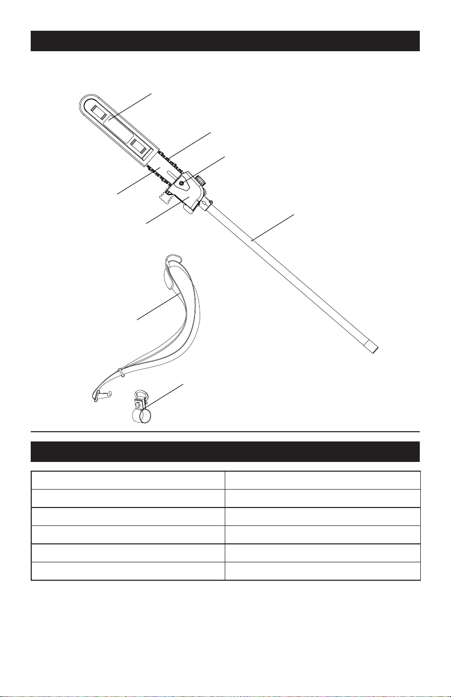
OVERVIEW
Guide bar length
10" (254 mm)
Chain pitch 3/8" LP (9.5 mm)
Chain gauge 0.05” (1.27 mm)
Chain oil capacity 80 ml
Chain 91PJ040X(Oregon)/CL15040X
Guide bar
100NDEA041(Oregon)/M1501040-1041TL
Lower Shaft
Scabbard
Chain Cover Lock Nut
Chain
Bar
Chain Cover
Shopuler Strap
Carrying Ring
SPECIFICATIONS

Page 8
The recommended ambient temperature range:
Item Temperature
Appliance storage temperature range 32°F (0°C) - 113°F (45°C)
Appliance operation temperature range 32°F (0°C) - 113°F (45°C)
Battery charging temperature range 39°F (4°C) - 104°F (40°C)
Charger operation temperature range 39°F (4°C) - 104°F (40°C)
Battery storage temperature range 32°F (0°C) - 113°F (45°C)
Battery discharging temperature range 32°F (0°C) - 113°F (45°C)
SPECIFICATIONS
Page 9
ASSEMBLY
UNPACKING
This product requires assembly.
• Carefully remove the product and any
accessories from the box. Make sure that all
items listed in the package contents section
are included.
• Inspect the product carefully to make sure
no breakage or damage occurred during
shipping.
• Do not discard the packing material until you
have carefully inspected and satisfactorily
operated the product.
• If any parts are damaged or missing, please
call 1-844-MSTR4CE (844-678-7423) for
assistance.
ADD THE BAR AND CHAIN OIL
Examine the amount of oil in the machine. If
the oil level is low, add the bar and chain oil as
follows.
IMPORTANT: Use bar and chain oil that is
only for chains and chain oilers.
NOTE: The machine comes from the factory
without bar and chain oil.
1. Loosen and remove the cap from the oil
tank.
2. Put the oil into the oil tank.
3. Monitor the oil indicator to make sure that
no dirt gets into the oil tank while you add
the oil.
4. Put the oil cap on.
5. Tighten the oil cap.
6. The whole oil tank will last for approximately
15 - 40 minutes.
IMPORTANT: Do not use dirty, used or
contaminated oil. Damage can occur to the
bar or chain.
WARNING
Do not allow familiarity
with this product to make you careless. Re-
member that a careless fraction of a second is
sufcient to inict serious injury.
WARNING
Do not use any attach-
ments or accessories not recommended by
the manufacturer of this product. The use of
attachments or accessories not recommended
can result in serious personal injury.
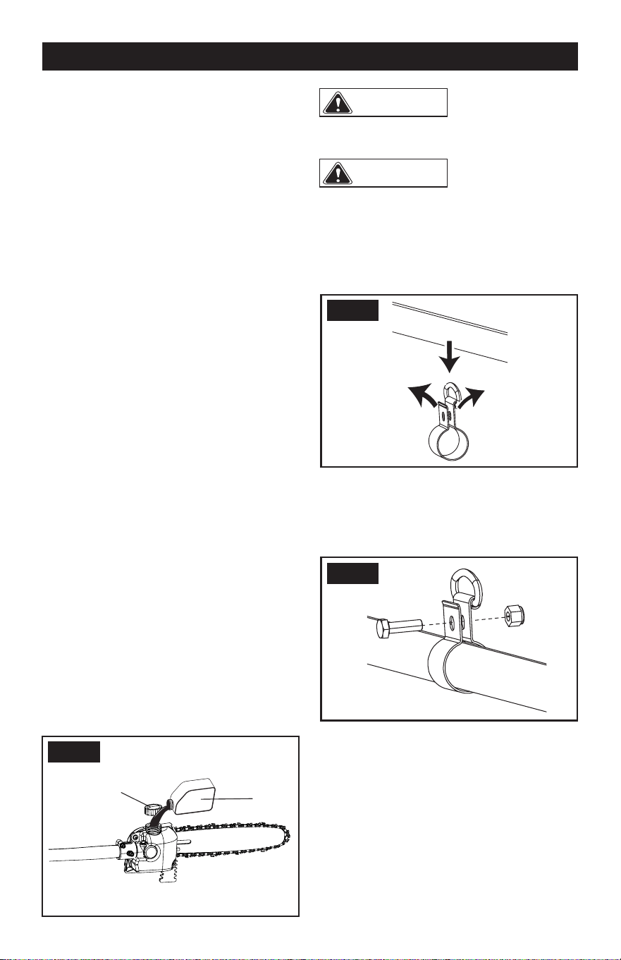
ATTACH THE CARRYING RING
1. Pull carrying ring apart and place over
power head end of shaft, position near the
power head.
2. Install bolt and locknut.
3. Tighten the nut securely.
ASSEMBLE THE SHAFT
To install the attachment to the power
head
The attachment connects to the power head
by means of a coupler device.
Oil Tank Cap
Oil
FIG. 1
FIG. 2
FIG. 3
Page 10
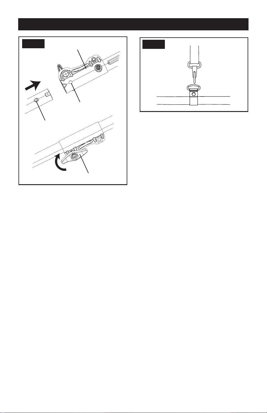
1. Loosen the attachment knob on the coupler.
2. Push in the release button located on the
attachment shaft.
3. Align the button with the guide recess on
the power head coupler and slide the two
shafts together.
4. Rotate the attachment shaft until the button
locks into the positioning hole.
NOTE:
If the button does not release
completely in the positioning hole, the shafts
are not locked into place. Slightly rotate from
side to side until the button is locked into
place.
5. Tighten the attachment knob securely.
To remove the attachment from the power
head
For removing or changing the attachment:
1. Stop the power head.
2. Remove the battery from the power head.
3. Loosen the attachment knob.
4. Push in the release button and twist the
shafts to remove and seperate ends.
USE THE SHOULDER STRAP
ASSEMBLY
FIG. 5
Release Button
Coupler
Guide Recess
Knob
FIG. 4
1. Attach the carabiner to the carrying ring on
the shaft.
2. Put on the shoulder strap.
3. Adjust the length of the strap so that the
carabiner is about the width of a hand below
your right hip.
CUTTING PREPARATION
Before you start to cut, make sure that you
• Wear heavy gloves for maximum grip and
protection.
• Maintain a proper grip on the machine
during operation.
• Use your right hand to grip the rear
handle while your left hand grips to the
pole shaft.
• Keep your body to the left of the chain
line.
• Never use a left-handed (cross-handed)
grip, or any stance that places your body
or arm across the chain line.
• Never stand directly under the limb you
are cutting.
• Periodically examine the tightness of the
collars during operation.
Page 11
OPERATION
EXAMINE THE CHAIN OIL
NOTE: Do not use the machine without
sufcient chain oil.
1. Examine the oil level of the machine from
the oil indicator.
2. Add the oil if it is necessary.
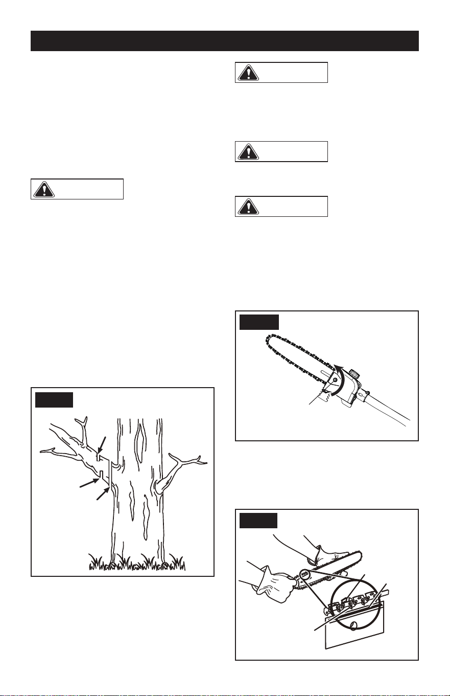
DELIMBING A TREE
WARNING
Ensure that the area
where the branches fall is clear of any objects
or individuals.
• Stand opposite the branch you will cut.
• Make a shallow rst cut (A) about 1/4 of
the limb's diameter on the underside of the
limb, close to the main limb or trunk.
• Make a second cut (B) from the top side of
the limb, outward from the rst cut.
• Make a nal cut (C) close to trunk.
NOTE: When making the second and nal
cuts from the top of the limb or branch, use
the spiked bumper against the part you're
cutting. This keeps the limb steady and
makes cutting easier.
CAUTION
Do not let brake
fluids, gasoline, petroleum-based materi-
als touch the plastic parts. Chemicals can
cause damage to the plastic, and make the
plastic unserviceable.
CAUTION
Do not use strong
solvents or detergents on the plastic
housing or components.
CAUTION
Remove the battery
pack from the machine before maintenance.
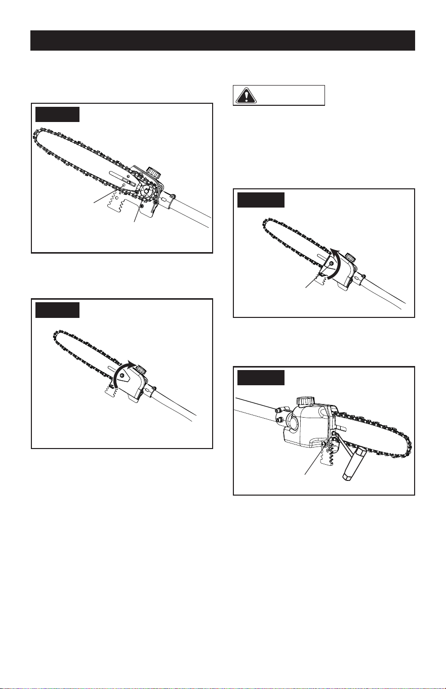
REPLACE THE GUIDE BAR AND
THE CHAIN
1. Loosen the chain cover by turning the
chain cover lock nut counterclockwise.
2. Remove the chain cover.
FIG. 4
3. Put the chain drive links into the bar
groove.
4. Put the chain cutters in the direction of
the chain operation.
5. Put the chain in position and make sure
that the loop is behind the guide bar.
FIG. 7
Chain Cutter
Bar Groove
Chain Drive Link
Chain Cover Lock Nut
A
B
C
FIG. 6
Page 12
MAINTENANCE
6. Hold the chain and bar.
7. Put the chain loop around the sprocket.
8. Make sure the chain tension pin hole on
the guide bar ts correctly with the bolt.
FIG. 8
9. Install the chain cover.
10. Tighten the chain. Refer to Adjust the
chain tension.
FIG. 9
11. Tighten the chain cover lock nut when the
chain is correctly tensioned.
NOTE: If you start the pole saw with a new
chain, check the tension after 2-3 minutes of
use. A new chain gets longer after the rst
use, examine the tension and tighten the
chain if necessary.
Chain Tension
Pin Hole
Sprocket
ADJUST THE CHAIN TENSION
CAUTION
Wear protective
gloves if you touch the chain, bar or areas
around the chain.
1. Loosen the chain cover by turning the
chain cover
lock nut
counterclockwise.
NOTE: It is not necessary to remove the
chain cover to adjust the chain tension.
FIG. 10
2. Turn the chain tension screw clockwise to
tighten the chain, or counterclockwise to
loosen it.
FIG. 11
3. When the chain is at the wanted tension,
tighten the chain cover.
Chain Cover Lock Nut
Chain Tension Screw
Page 13
FIG. 14
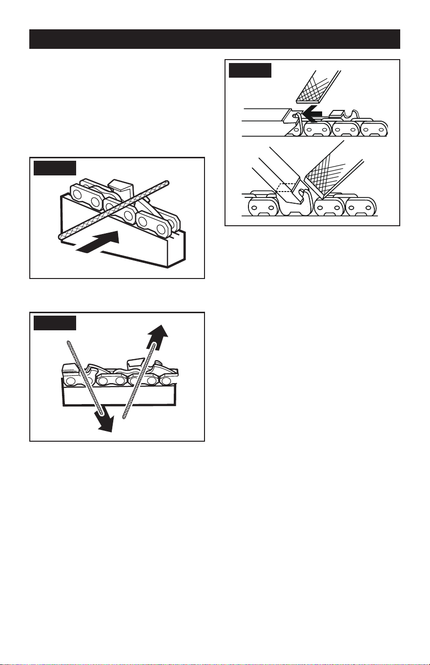
4. File all the cutters to the specied angles
and the same length.
NOTE: During the process,
• Keep the le at with the surface to be
sharpened.
• Use the midpoint of the le bar.
• Use light but rm pressure when
sharpening the surface.
• Lift the le away on each return stroke.
• Sharpen the cutters on one side and then
move to the other side.
Replace the chain if:
• The length of the cutting edges is less than
5 mm.
• There is too much space between the drive
links and the rivets.
• The cut speed is slow.
• Sharpening the chain many times but it
does not increase the cutting speed. The
chain is worn.
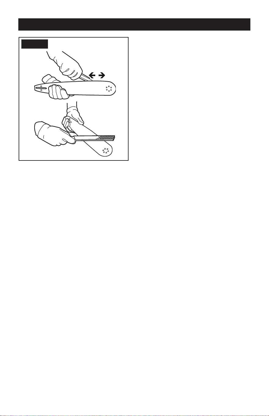
GUIDE BAR MAINTENANCE
NOTE: Make sure that it is turned over
periodically to keep symmetrical wear on the
bar.
1. Lubricate the bearings on the nose
sprocket (if present) with the syringe (not
included).
2. Clean the bar groove with a scraping
hook (not included).
3. Clean the lubrication holes.
4. Remove burr from the edges and level
the cutters with a at le.
SHARPEN THE CUTTERS
Sharpen the cutters if it is not easy for the
chain to cut into the wood.
NOTE: We recommend that a service center,
which has an electric sharpener, perform
important sharpening work.
1. Tensioning chain.
FIG. 12
2. Sharpen the cutters corner with a 5/32 in.
(4 mm) diameter round le.
FIG. 13
3. Sharpen the top plate, side plate and
depth gauge with a at le.
MAINTENANCE
Page 14
MAINTENANCE
FIG. 15
Replace the bar if:
• the groove does not t with the height of
the drive links (which must never touch the
bottom).
• the inside of the guide bar is worn and
makes the chain lean to one side.
TRANSPORTATION AND
STORAGE
Before you move the machine, always
• Remove the battery pack from the machine.
• Keep hands clear of the trigger lock.
• Put the scabbard on the guide bar and the
chain.
Before you put the machine into storage,
always
• Remove the battery pack from the machine.
• Clean all unwanted material from the
machine.
• Make sure that the storage area is
• Not available to children.
• Away from agents which can cause
corrosion, such as garden chemicals
and de-icing salts.

Page 15
PROBLEM POSSIBLE CAUSE SOLUTION
The machine does
not start.
The poles are not
assembled correctly.
Assemble the poles according to the
instructions.
The trigger lock and
trigger are not depressed
at the same time.
1. Push and hold the trigger lock.
2. While you hold the trigger lock, pull the
trigger.
3. Release the trigger lock to start the
machine.
The bar and chain
gets hot and smokes.
Oil tank is empty. Fill the oil tank.
The discharge port is
blocked.
Refer to the manual to remove the bar and
clean out the debris.
Inlet opening of inner oil
tank is blocked.
1. Clean the oil tank.
2. Fill with clean bar and chain oil.
The sprocket is stuck and
clogged with debris.
1. Clean the sprocket.
2. Fill with clean bar and chain oil.
The bar and chain
gets too hot and can
not cut.
The chain tension is too
tight or too loose.
Refer to Adjust the Chain Tension in the
manual.
The chain is dull. Sharpen or replace the chain.
The chain is put on
backwards.
Take out the chain and turn it in the right
direction.
The motor runs, but
the chain does not cut
correctly, or the motor
stops after around 3
seconds.
When you use the
machine under load, it
stops.
1. Release the trigger.
2. Start the machine again.
The chain is not lubricated. Lubricate the chain to decrease the
friction.
TROUBLESHOOTING

Page 16
NOTES

Page 17
SAVE YOUR RECEIPTS
THIS WARRANTY IS VOID WITHOUT THEM
POLE SAW ATTACHMENT
WARRANTY
4-YEAR LIMITED WARRANTY
This MASTERFORCE™ brand power tool carries our famous No Hassle 4-Year Limited
Warranty to the original purchaser. If, during normal use, this MASTERFORCE™ power
tool breaks or fails due to a defect in material or workmanship within four (4) years from
the date of original purchase, simply bring the tool with the original sales receipt back
to your nearest MENARDS
®
retail store. At its discretion, MASTERFORCE™ agrees
to have the tool or any defective part(s) repaired or replaced with the same or similar
MASTERFORCE™ product or part free of charge, within the stated warranty period,
when returned by the original purchaser with original sales receipt. Not withstanding the
foregoing, this limited warranty does not cover any damage that has resulted from abuse
or misuse of the Merchandise. This warranty: (1) excludes expendable parts including
but not limited to blades, brushes, belts, bits, light bulbs, and/or batteries; (2) shall be
void if this tool is used for commercial and/or rental purposes; and (3) does not cover any
losses, injuries to persons/property or costs. This warranty does give you specific legal
rights and you may have other rights, which vary from state to state. Be careful, tools
are dangerous if improperly used or maintained. Seller’s employees are not qualified
to advise you on the use of this merchandise. Any oral representation(s) made will not
be binding on seller or its employees. The rights under this limited warranty are to the
original purchaser of the merchandise and may not be transferred to any subsequent
owner. This limited warranty is in lieu of all warranties, expressed or implied including
warranties or merchantability and fitness for a particular purpose. Seller shall not be
liable for any special, incidental, or consequential damages. The sole exclusive remedy
against the seller will be for the replacement of any defects as provided herein, as long
as the seller is willing or able to replace this product or is willing to refund the purchase
price as provided above. For insurance purposes seller is not allowed to demonstrate
any of these power tools for you.
For questions / comments, technical assistance or repair parts -
Please call toll free at: 1-844-678-7423 (M-F 8am - 6pm)

© 2023 Menard, Inc., Eau Claire, WI 54703 9/2023