HDS 200/HDS 250 HD Scan Tool
for Class 4-8 Diesel, Light and Medium Vehicles
en User guide

en
|
2
|
User guide
| HDS 200/HDS 250
HD Scan Tool for Class 4-8 Diesel, Light and Medium Vehicles
581618 | REV. B | 11.2018
Bosch Automotive Service Solutions Inc.
Serial No: __________________________________
SW ID: _____________________________________
HW Ver: ____________________________________
Boot Ver: ___________________________________
Prod ID: ____________________________________
Board ID: ___________________________________
Burn Date: _________________________________
Record the above information about your tool. The information is available
at Main Menu --> System Setup --> Tool Information. Provide this informa-
tion when contacting technical support.
If you have questions or concerns contact Technical Support:
Phone: 1-855-267-2483
E-mail: techsuppor[email protected]
The information, specifications and illustrations in this guide are based on
the latest information available. Bosch reserves the right to make changes
at any time without notice.

581618 | REV. B | 11.2018
Bosch Automotive Service Solutions Inc.
HDS 200/HDS 250
HD Scan Tool for Class 4-8 Diesel, Light and Medium Vehicles
|
User guide | 3
|
en
Table of Contents
1 Safety Precautions ....................... 4
1.1 Read All Instructions ................ 4
1.2 Safety Messages ................... 4
2 Important Safety Warnings and Instructions .. 4
3 Getting Started .........................7
3.1 Introduction .......................7
3.2 Download Scanning Suite ............ 7
3.3 Introduction to On-Board Diagnostics ...7
SAE J1587/J1708 ................... 7
SAE J1939 ........................ 7
OBD II ............................7
3.4 SAE Publications ...................8
3.5 Data Link Connector (DLC) ........... 8
J1939 Type 2 ....................... 8
J1708/J1587 ....................... 8
OBD II (J1962) ..................... 8
OBD II Data Link Connector (DLC) Pins ..9
3.6 J1939 Diagnostic Trouble Codes ....... 9
3.7 J1587 Diagnostic Trouble Codes ....... 9
3.8 OBD II Diagnostic Trouble Codes (DTCs) 9
Powertrain Codes ...................9
Chassis Codes ......................9
Body Codes ........................9
Network Communication Codes ........9
4 Using the Scan Tool ..................... 10
4.1 The Scan Tool ..................... 10
4.2 Specifications ..................... 10
Dimensions .......................10
Accessories .......................10
Optional Accessories ............... 10
4.3 Display .......................... 11
Keypad .......................... 11
4.4 Power ........................... 11
Internal Battery Power .............. 11
Vehicle Power ..................... 11
USB Power .......................11
4.5 System Setup ..................... 11
Changing Measurement Units .........11
Changing Auto-Power Off ............ 12
Quick Test ........................ 12
Print Header ......................13
Language Setup ...................13
Long PID/SPN Names ...............13
Pre-Trigger Setup .................. 14
Tool Information ................... 14
Display Test .......................15
Keypad Test ....................... 15
Memory Test ...................... 16
Program Mode .................... 16
4.6 Vehicle-Specific Features ............ 16
Review Data ...................... 16
Recording ........................17
Print Data ........................ 18
4.7 Locating Data Link Connector ........ 18
4.8 Connect the Tool .................. 18
4.9 Vehicle Selection ..................18
5 Heavy Duty Standard Diagnostics .......... 19
5.1 Read Codes ...................... 20
Lamp Status ......................21
Erase ............................21
5.2 Erase Codes ...................... 21
5.3 View Data ........................22
View Entire List .................... 23
Custom List Select ................. 24
5.4 Record Data ...................... 25
5.5 Module Information ................26
5.6 Vehicle Information ................ 27
6 OBD II Diagnostics ......................27
6.1 I/M Monitors (Emissions) ........... 28
6.2 Read Codes ...................... 29
6.3 Erase Codes ...................... 30
6.4 MIL Status .......................31
6.5 State OBD Check ..................31
6.6 View Data ........................31
View Entire List .................... 32
Custom List Select ................. 33
6.7 Record Data ...................... 34
6.8 View Freeze Data ..................35
6.9 Drive Cycle Monitor ................ 35
6.10 O2 Monitor Tests ..................36
6.11 Diagnostic Monitor Tests ............ 37
6.12 On-Board Systems ................. 38
6.13 Vehicle Information ................ 39
6.14 Modules Present .................. 40
7 Troubleshooting ........................41
7.1 Error Messages ................... 41
7.2 Scan Tool Does Not Power Up ........41
7.3 Vehicle Communication Fault ........ 42
7.4 Operating Error or Erroneous Data .... 42
7.5 Battery Replacement ............... 42
7.6 Tool Self-Tests .................... 42
7.7 Technical Support ................. 42
8 Appendix A—Global OBD II PID Definitions ... 42
9 Appendix B—Glossary ...................45
10 Third Party Licenses .................... 51
11 Limited Warranty .......................51
en
|
4
|
User guide
| HDS 200/HDS 250
HD Scan Tool for Class 4-8 Diesel, Light and Medium Vehicles
581618 | REV. B | 11.2018
Bosch Automotive Service Solutions Inc.
1 Safety Precautions
For your safety, read this manual thoroughly before
operating your scan tool. Always refer to and follow
safety messages and test procedures provided by the
manufacturer of the vehicle or equipment being tested.
The safety messages presented below and throughout
this user’s manual are reminders to the operator to
exercise extreme care when using this test instrument.
1.1 Read All Instructions
Read and understand the user guide be-
fore operating the tool.
Read, understand, and follow all safety messages and
instructions in this manual and on the test equipment.
Safety messages in this section of the manual contain a
signal word with a three-part message and, in some
instances, an icon.
1.2 Safety Messages
Safety messages are provided to help prevent personal
injury and equipment damage. All safety messages are
introduced by a signal word. The signal word indicates
the level of the hazard in a situation. The types of safety
messages are.
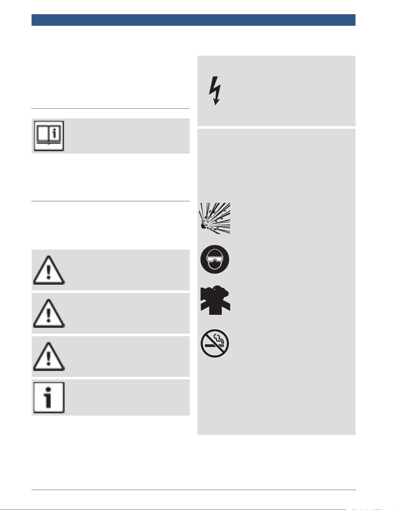
DANGER
Indicates a possible hazardous situation
which, if not avoided, will result in death
or serious injury to operator or bystand-
ers.
WARNING
Indicates a possible hazardous situa-
tion which, if not avoided, could result
in death or serious injury to operator or
bystanders.
CAUTION
Indicates a possible hazardous situa-
tion which, if not avoided, may result in
moderate or minor injury to operator or
bystanders.
IMPORTANT
Indicates a condition which, if not avoid-
ed, may result in damage to test equip-
ment or vehicle.
2 Important Safety Warnings
and Instructions
WARNING
Risk of electric shock.
• Do not exceed voltage limits between
inputs indicated in the Specifications.
• Use extreme caution when working
with circuits that have voltage greater
than 60 volts DC or 24 volts AC.
Electric shock can cause injury.
WARNING
Risk of poisoning.
• Safety goggles and protective clothing must
be worn by the operator and any bystanders.
– Even if everyday glasses have
impact resistant lenses, they are
NOT safety glasses, and may not
provide adequate protection.
• Do not use this scan tool in environ-
ments where explosive vapors may
collect. These areas include:
– below-ground pits.
– confined areas.
– areas that are less than 18 inches
above floor.
• Use this scan tool in locations with
mechanical ventilation providing at
least 4 air changes per hour.
• Flammable fuel and vapors can ignite.
• Do not smoke, strike a match, or cause
a spark in the vicinity of the battery.
Battery gases can ignite.
• Avoid making an accidental connection
between the battery terminals. Do not place
uninsulated metal tools on the battery.
• When removing battery cables, remove
the ground cable first.
• Avoid sparks when connecting or dis-
connecting power leads to the battery.
• Make sure ignition is off, headlights
and other accessories are off and
vehicle doors are closed before dis-
connecting the battery cables.
– This also helps prevent damage to
on-board computer systems.
• Always disconnect the battery ground
connections before servicing electri-
cal system components.
Explosion can cause injury.
581618 | REV. B | 11.2018
Bosch Automotive Service Solutions Inc.
HDS 200/HDS 250
HD Scan Tool for Class 4-8 Diesel, Light and Medium Vehicles
|
User guide | 5
|
en
WARNING
Risk of poisoning.
• Use this scan tool in locations with
mechanical ventilation providing at
least 4 air changes per hour. Engine
exhaust contains odorless gas which
can be lethal.
• Route the exhaust outside while
testing with the engine running.
Poisoning can result in death or serious injury.
WARNING
Battery acid is a highly corrosive sulfuric acid.
• Safety goggles and protective gloves must be
worn by the operator and any bystanders.
– Even if your everyday glasses
have impact resistant lenses, they
are NOT safety glasses, and may
not provide adequate protection.
• Make sure someone can hear you or is
close enough to provide aid when
working near a battery.
• Have plenty of fresh water and soap nearby.
– If battery acid contacts skin,
clothing, or eyes, flush exposed
area with soap and water for 10
minutes. Seek medical help.
• Do not touch eyes while working near battery.
Battery acid can burn eyes and skin.
WARNING
Risk of fire.
• Safety goggles and protective clothing must
be worn by the operator and any bystanders.
– Even if your everyday glasses
have impact resistant lenses, they
are NOT safety glasses, and may
not provide adequate protection.
• Do not position your head directly in
front of or over the throttle body.
• Do not pour gasoline down the throt-
tle body when cranking or running the
engine, when working with fuel deliv-
ery systems or any open fuel line.
– Engine backfire can occur when
the air cleaner is out of position.
• Do not use fuel injector cleaning solvents
when performing diagnostic testing.
• Keep cigarettes, sparks, open flame
and other sources of ignition away
from vehicle.
• Keep a dry chemical (Class B) fire
extinguisher rated for gasoline, chemi-
cal and electrical fires in work area.
Fire can cause death or serious injury.
WARNING
Risk of flying particles.
• Safety goggles and protective gloves must
be worn by the operator and any bystand-
ers while using electrical equipment.
– Electrical equipment or rotating
engine parts can cause flying particles.
– Even if your everyday glasses
have impact resistant lenses, they
are NOT safety glasses, and may
not provide adequate protection.
Flying particles can cause eye injury.
WARNING
Risk of burns.
• Batteries can produce a short-circuit
current high enough to weld jewelry
to metal.
– Remove jewelry such as rings,
bracelets and watches before
working near batteries.
Short circuits can cause injury.
WARNING
Risk of burns.
• Do not remove radiator cap unless
engine is cold.
– Pressurized engine coolant may
be hot.
• Do not touch hot exhaust systems, mani-
folds, engines, radiators, sample probe.
• Wear insulated gloves when handling
hot engine components.
• Tester leads can become hot after extended
testing in close proximity to manifolds.
Hot components can cause injury.
WARNING
Risk of expelling fuel, oil vapors, hot steam,
hot toxic exhaust gases, acid, refrigerant
and other debris.
• Safety goggles and protective clothing
must be worn by the operator and any
bystanders.
– Even if your everyday glasses
have impact resistant lenses, they
are NOT safety glasses, and may
not provide adequate protection.
• Engine systems can malfunction,
expelling fuel, oil vapors, hot steam,
hot toxic exhaust gases, acid, refriger-
ant and other debris.
Fuel, oil vapors, hot steam, hot toxic
exhaust gases, acid, refrigerant and other
debris can cause serious injury.
en
|
6
|
User guide
| HDS 200/HDS 250
HD Scan Tool for Class 4-8 Diesel, Light and Medium Vehicles
581618 | REV. B | 11.2018
Bosch Automotive Service Solutions Inc.
WARNING
Engine compartment contains electrical
connections and hot or moving parts.
• Keep yourself, test leads, clothing and
other objects clear of electrical connec-
tions and hot or moving engine parts.
• Do not wear watches, rings, or loose
fitting clothing when working in an
engine compartment.
• Do not place tools or test equipment
on fenders or other places in engine
compartment.
• Barriers are recommended to help
identify danger zones in test area.
• Prevent personnel from walking
through test area.
Contacting electrical connections and hot
or moving parts can cause injury.
WARNING
Risk of injury.
• The scan tool should be operated by
qualified personnel only.
• Use the scan tool only as described in
the user’s manual.
• Use only manufacturer’s recom-
mended attachments.
• Do not operate the scan tool with
damaged cables.
• Do not operate the scan tool if it has
been dropped or damaged, until exam-
ined by a qualified service representative.
Operation of the scan tool by anyone other
than qualified personnel may result in injury.
P R N D L 2
WARNING
Risk of unexpected vehicle movement.
• Block drive wheels before performing
a test with engine running.
• Unless instructed otherwise:
– set parking brake
– put gear selector in neutral for
manual transmissions
– put gear selector in park for
automatic transmissions
– disconnect release mechanism on
the automatic parking brake
release for testing and reconnect
when testing is completed.
• Do not leave a running engine unattended.
A moving vehicle can cause injury.
CAUTION
Risk of equipment or circuit damage.
• Unless specifically directed by manufac-
turer, make sure ignition is off before
connecting or disconnecting connectors
or any vehicle electrical terminals.
• Do not create a short between battery
terminals with a jumper wire or tools.
Improper equipment use can cause equip-
ment or circuit damage.
CAUTION
Misdiagnosis may lead to incorrect or
improper repair and/or adjustment.
• Do not rely on erratic, questionable,
or obviously erroneous test informa-
tion or results.
– If test information or results are
erratic, questionable, or obviously
erroneous, make sure all connec-
tions and data entry information
are correct and test procedures
were performed correctly.
– If test information or results are
still suspicious, do not use them
for diagnosis.
Improper repair and/or adjustment may
cause vehicle or equipment damage or
unsafe operation.
DANGER
Some vehicles are equipped with air bags.
• Follow service manual warnings when
working around air bag components
or wiring.
– If service manual instructions are
not followed, an air bag may deploy
unexpectedly, resulting in injury.
– Note an air bag can still deploy
several minutes after ignition key
is off (or even if vehicle battery is
disconnected) because of a
special energy reserve module.
An air bag opening can cause injury.

581618 | REV. B | 11.2018
Bosch Automotive Service Solutions Inc.
HDS 200/HDS 250
HD Scan Tool for Class 4-8 Diesel, Light and Medium Vehicles
|
User guide | 7
|
en
3 Getting Started
3.1 Introduction
The scan tool was developed by experts in the Heavy
Duty Diesel and automotive service industry to help
diagnose vehicles and assist in troubleshooting proce-
dures.
The scan tool monitors vehicle events and retrieves
codes from the vehicle’s control modules to help pin-
point problem areas.
All information, illustrations and specifications con-
tained in this manual are based on the latest information
available from industry sources at the time of publica-
tion.
No warranty (expressed or implied) can be made for its
accuracy or completeness, nor is any responsibility
assumed by the manufacturer or anyone connected with
it for loss or damages suffered through reliance on any
information contained in this manual or misuse of
accompanying product. The manufacturer reserves the
right to make changes at any time to this manual or
accompanying product without obligation to notify any
person or organization of such changes.
3.2 Download Scanning Suite
• Download the Scanning Suite PC application here:
– https://www.boschdiagnostics.com/pro/prod-
ucts/Bosch-HDS-200
– https://www.boschdiagnostics.com/pro/prod-
ucts/Bosch-HDS-250
• Scanning Suite is NOT required to operate the Scan
Tool.
• Install the downloaded Scanning Suite application
prior to connecting the Scan Tool to the PC.
• Some of the items included in Scanning Suite are:
– Tool update software
– Print Capture
• To be able to use Scanning Suite the PC must meet
the following minimum requirements:
– Microsoft Windows 7, 8, and 10.
– Adobe Acrobat Reader
– Screen Resolution of 800 x 600
– If screen resolution is 800 x 600, in Display
Properties, Settings Tab, set Font Size to Small
Fonts.
• Use Scanning Suite to determine if any updates are
available for your tool by clicking Check for Update
button.
• You can also configure the Scanning Suite Frequency
(SS Frequency) to automatically check every xx
minutes. The default frequency is 30 minutes.
• Find instructions on how to install Scanning Suite
and Tool updates here:
– https://www.boschdiagnostics.com/pro/prod-
ucts/Bosch-HDS-200
– https://www.boschdiagnostics.com/pro/prod-
ucts/Bosch-HDS-250
3.3 Introduction to On-Board Diagnostics
SAE J1587/J1708
SAE J1587 is a diagnostic protocol standard developed
by the Society of Automotive Engineers (SAE) for heavy-
duty and most medium-duty vehicles built after 1985. Up
to 1995, individual OEMs used their own connectors.
From 1996 to 2001, the 6-pin Deutsch was standard.
Beginning in 2001, most OEMs converted to the 9-pin
Deutsch. Some OEMs still use the 6-pin Deutsch.
SAE J1708 is an SAE physical specification developed
for heavy duty vehi cles (trucks and busses). The proto-
col promoted a standard for serial communication
between modules with microcontrollers. J1708
describes the physical and data link layer. Almost always
used in conjunction with the application layer protocol
SAE J1587.
SAE J1939
In the early 90’s, the SAE Truck and Bus Control and
Communications Sub-committee started the develop-
ment of a CAN-based application pro file for in-vehicle
communication in trucks. In 1998, the SAE published the
J1939 set of specifications. A J1939 network connects
electronic control units (ECU) within a truck and trailer
system. The J1939 specification - with its engine, trans-
mission, and brake message definitions - is dedicated to
diesel engine applications.
SAE J1939 has been adopted widely by diesel engine
manufacturers. One driving force behind this is the
increasing adoption of the engine Elec tronic Control
Unit (ECU), which provides one method of controlling
exhaust gas emissions within US and European stan-
dards. Consequently, SAE J1939 can now be found in a
range of diesel-powered applications: vehicles (on- and
off-road), marine propulsion, power generation, and
industrial pumping.
OBD II
On-Board Diagnostics version II (OBD II) is a system that
the Society of Automotive Engineers (SAE) developed to
standardize automotive electronic diagnosis.
Beginning in 1996, most new vehicles sold in the United
States were fully OBD II compliant.
Technicians can now use the same tool to test any OBD
II compliant vehicle without special adapters. SAE estab-
lished guidelines that provide:
• A universal OBD II data link connector, called the
DLC, with dedicated pin assignments.
• Diagnostics with vehicle modules involved in emis-
sions controls such as ECM/PCM & transmission.
• A standard location for the DLC, visible under the
dash on driver’s side.
• A standard list of diagnostic trouble codes (DTCs)
used by all manufacturers.
• A standard list of parameter identification (PID) data
used by all manufacturers.
en
|
8
|
User guide
| HDS 200/HDS 250
HD Scan Tool for Class 4-8 Diesel, Light and Medium Vehicles
581618 | REV. B | 11.2018
Bosch Automotive Service Solutions Inc.
• Ability for vehicle systems to record operating condi-
tions when a fault occurs.
• Expanded diagnostic capabilities that records a
code whenever a condition occurs that affects
vehicle emissions.
• Ability to clear stored codes from the vehicle’s
memory with a scan tool.
3.4 SAE Publications
SAE has published hundreds of pages of text defining a
standard communication protocol that establishes hard-
ware, software, and circuit parameters of OBD II sys-
tems. Unfortunately, vehicle manufacturers have differ-
ent interpretations of this standard communications
protocol. As a result, the generic OBD II communications
scheme varies, depending on the vehicle. SAE publishes
recommendations, not laws, but the Environmental
Protection Agency (EPA) and California Air Resources
Board (CARB) made many of SAE’s recommendations
legal requirements that vehicle manufacturers were
required to phase in over a three-year period. Beginning
in 1994, vehicles with a new engine management com-
puter (about 10% of each manufacturers fleet) were sup-
posed to comply with OBD II standards. For 1995, OBD
II systems were to appear on about 40% of the new
vehicles sold in the United States. Some of the 1994-
1995 OBD II systems were not fully compliant, so the
Government granted waivers to give manufacturers time
to fine-tune their systems. Beginning in 1996, most of
the new vehicles sold in the United States were fully
OBD II compliant.
3.5 Data Link Connector (DLC)
The data link connector (DLC) allows the scan tool to
communicate with the vehicle’s computer(s). Use the
proper DLC adapter cable to connect the scan tool to
the vehicle. Also, the vehicle’s DLC may be found in
several different places and have many different configu-
rations.
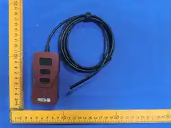
IMPORTANT
Power to the tool generally comes from
the vehicle. If the tool does not power-up,
use the included cigarette lighter cable
(7-0135) to power-up the tool.
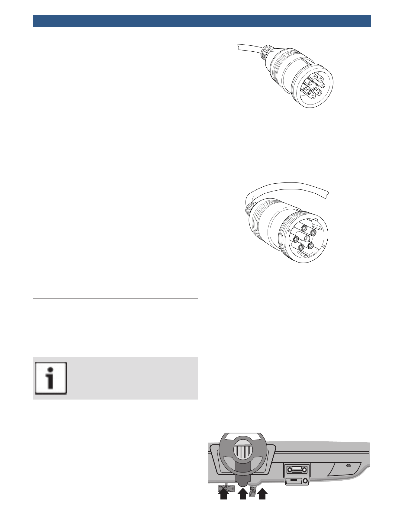
J1939 Type 2
The J1939 Type 2 is a round 9-pin green DLC adapter
cable (HDS 200: 1699200242) (HDS 250: 1699200245).
This cable will work on trucks with older J1939 Type 1
and new J1939 Type 2 DLCs.
The vehicle DLC is generally mounted inside the cab.
For on road heavy trucks, the connector should be
mounted on the driver side. For busses, the vehicle DLC
should be mounted within reach of the operators seat.
Attach the 9-pin green adapter cable to the extender
cable (7-0137) (both supplied with the scan tool) to con-
nect the tool.
J1708/J1587
The J1708/J1587 connector is a round 6-pin gray DLC
adapter cable (HDS 200: 1699200241) (HDS 250:
1699200244).
Attach the 6-pin grey adapter cable to the extender cable
(7-0137) (both supplied with the scan tool) to connect
the tool.
OBD II (J1962)
Beginning in 1996, vehicles sold in the United States use
the J1962 (OBD II) DLC, a term taken from a physical
and electrical specification number assigned by the SAE
(J1962). The DLC should be located under the dash-
board on the driver’s side of the vehicle. If the DLC is
not located under the dashboard as stated, a decal
describing its location should be attached to the dash-
board in the area the DLC should have been located. For
more information on OBD II connectors, go to
http://www.obdclearinghouse.com.
Because the OBD II J1962 connector has power and
ground, you only need a single cable connection to the
tool for both power and vehicle communications. Attach
the OBD II adapter cable (HDS 200: 1699200243) (HDS
250: 1699200246) to the extender cable (7-0137) (both
supplied with the scan tool), to
connect the tool. Certain pins in the connector are
reserved.
581618 | REV. B | 11.2018
Bosch Automotive Service Solutions Inc.
HDS 200/HDS 250
HD Scan Tool for Class 4-8 Diesel, Light and Medium Vehicles
|
User guide | 9
|
en
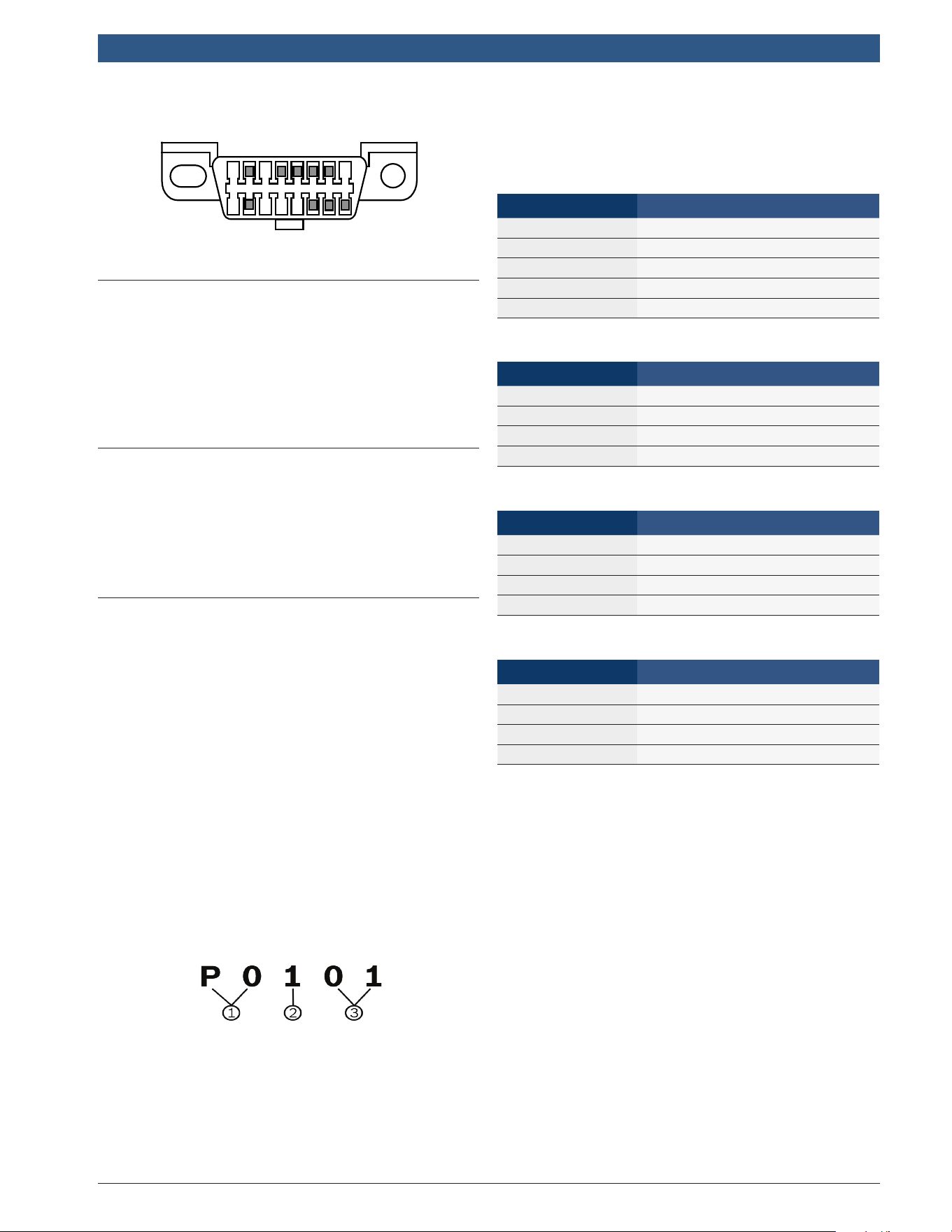
OBD II Data Link Connector (DLC) Pins
1 8
9 16
3.6 J1939 Diagnostic Trouble Codes
J1939 DTCs are made up of a Suspect Parameter Num-
ber (SPN) and the Failure Mode Identifier (FMI). The
SPN identifies the failed component or system. The FMI
identifies the type of failure.
J1939 defines a standard set of DTCs. SAE reserves
SPNs 0 to 516095. SPNs 516096 to 524287 are
reserved for the manufacturer.
3.7 J1587 Diagnostic Trouble Codes
J1587 DTCs are made up of either a Parameter Identifi-
cation number (PID) or a Subsystem Identification
number (SID). It is also made up of a Failure Mode
Identifier (FMI). The SID or PID identifies the failed
component or system. The FMI identifies the type of
failure.
3.8 OBD II Diagnostic Trouble Codes
(DTCs)
J2012 and ISO 15031-6 are standards for all DTCs,
established by the SAE, International Organization for
Standardization (ISO) and other governing bodies.
• Codes and definitions assigned by these specifica-
tions are known as Generic OBD II codes.
• OBD II requires compliance to these standards for
all cars, light trucks, APVs, MPVs, and SUVs sold in
the United States.
• Codes not reserved by the SAE are reserved for the
manufacturer and referred to as Manufacturer Spe-
cific Codes.
DTCs are used to help determine the cause of a problem
or problems with a vehicle.
• DTCs consist of a five-digit alphanumeric code.
• The DTCs format and general code types are shown
below.
1. Bx = Body
Cx = Chassis
Px = Powertrain
Ux = Network communication
x = 0, 1, 2, or 3
2. Vehicle specific system
3. Specific fault designation
Example:
P0101 = Mass or volume air flow cir cuit range/perfor-
mance problem
Powertrain Codes
Code Type
P0xxx Generic (SAE)
P1xxx Manufacturer specific
P2xxx Generic (SAE)
P30xx–P33xx Manufacturer specific
P34xx–P39xx Generic (SAE)
Chassis Codes
Code Type
C0xxx Generic (SAE)
C1xxx Manufacturer specific
C2xxx Manufacturer specific
C3xxx Generic (SAE)
Body Codes
Code Type
B0xxx Generic (SAE)
B1xxx Manufacturer specific
B2xxx Manufacturer specific
B3xxx Generic (SAE)
Network Communication Codes
Code Type
U0xxx Generic (SAE)
U1xxx Manufacturer specific
U2xxx Manufacturer specific
U3xxx Generic (SAE)
en
|
10
|
User guide
| HDS 200/HDS 250
HD Scan Tool for Class 4-8 Diesel, Light and Medium Vehicles
581618 | REV. B | 11.2018
Bosch Automotive Service Solutions Inc.
4 Using the Scan Tool
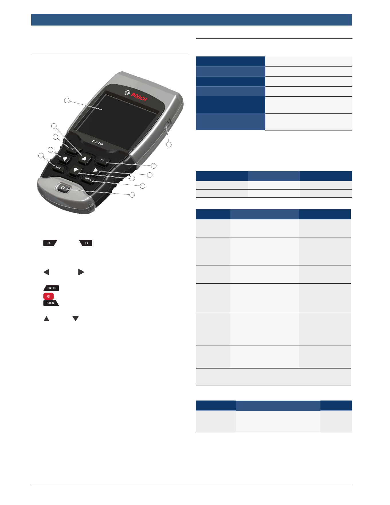
4.1 The Scan Tool
2
4
5
3
7
7
2
3
6
8
1
1. USB port - provides USB connection for the com-
puter.
2. F1 and F2 keys are used to perform the
specified action on the display directly above the
key. If nothing appears on the display directly above
the F1 and F2 keys, then the keys are inactive.
3. LEFT and RIGHT arrow keys - selects YES or
NO and selects data parameters for custom data list.
4. ENTER key - selects displayed items.
5. ON/OFF key - turns power ON or OFF.
6. BACK key - goes to the previous screen or
level.
7. UP and DOWN arrow keys - moves selection up
or down.
8. LCD display (color, backlit, QVGA resolution)
9. DLC cable (not shown) - provides connection for
vehicle interface.
10. Serial Number Plate (not shown) - Located inside
battery compartment, provides serial number of
scan tool.
11. Battery Compartment (on back; not shown) - pro-
vides power to the scan tool when reprogramming
from a personal computer or off-vehicle reviewing of
codes and printing.
12. 12V Power Jack (not shown) - provides power to
scan tool when scan tool is conneced to certain
Heavy Duty vehicles.
4.2 Specifications
Display Color, backlit, QVGA resolution
Operating Temperature
0 to 50°C (32 to 122°F)
Storage Temperature -20 to 70°C (-4 to 158°F)
Internal Power
4-AAA Batteries
Barrel Jack
External Power
7 to 16 Volts
DLC Adapter Cable
External Power
HDS 200: 7 to 16 Volts
HDS 250: 7 to 36 Volts
A minimum of 8.0 V is required for most control modules
to operate properly in a vehicle.
Dimensions
Height Width Depth
7 inches 3.75 inches 1.125 inches
178 mm 95 mm 29 mm
Accessories
Part Description Part No.
Extender
Cable
Cable used to connect
vehicle specific adapter
cables to scan tool
7-0137
OBD II
Cable
Communicates
between vehicle and
tool
1699200243
(HDS 200)
1699200246
(HDS 250)
Cigarette
Lighter
Cable
Cable used to power
scan tool from cigarette
lighter.
7-0135
9-pin
Deutsch
Cable
Refer to page 8
1699200242
(HDS 200)
1699200245
(HDS 250)
6-Pin
Deutsch
Cable
Refer to page 8
1699200241
(HDS 200)
1699501129
*formerly 1699200244
(HDS 250)
USB Cable
Cable used to update
scan tool firmware and
print data to Scanning
Suite
0038-000-3430
* Some units were originally shipped with a 6-Pin Deutsch Cable (Part No.
1699200244). When replacing this cable, the 6-Pin Deutsch Cable (Part No.
1699501129) should be purchased.
Optional Accessories
Part Description Part No.
Battery Clip
Y Adapter
Cable
Adapter that allows the
Cigarette Lighter Cable to
connect directly to vehicle
battery cables
7-0136
Replacement parts are available from the manufacturer
by contacting customer service at 1-855-267-2483 (8:00-
6:00 EST Monday-Friday).
581618 | REV. B | 11.2018
Bosch Automotive Service Solutions Inc.
HDS 200/HDS 250
HD Scan Tool for Class 4-8 Diesel, Light and Medium Vehicles
|
User guide | 11
|
en
4.3 Display
The display has a large viewing area for displaying mes-
sages, instructions, and diagnostic information.
The back-lit liquid crystal display (LCD) is a QVGA pixel
display. Display icons used to help operate the scan tool
are:
• Indicates additional information is available by
scrolling down.
• Indicates additional information is available by
scrolling up.
• Indicates the internal batteries need replaced or
are not installed.
• √ Indicates selected items in a data list or that data
is available for items on the Review Data and Print
Data Menu.
• Indicates graphical viewing of data items is
available in View Data and when playing back previ-
ously recorded data.
Keypad
The keypad is used to move through the different menus
of the scan tool. The scan tool’s software is designed for
ease in operating and navigating through menus.
CAUTION
Do not use solvents such as alcohol to clean
keypad or display. Use a mild nonabrasive
detergent and a soft, cotton cloth.
CAUTION
Do not soak keypad as water might find
its way inside the scan tool.
4.4 Power
Internal Battery Power
• Battery power is not required to use tool.
• Press and hold ON/OFF key for at least 1 sec-
ond to turn ON scan tool.
• The scan tool will autmatically turn OFF after a
user-selectable period of inactivity when powered
from the internal batteries. The default is 2 minutes.
• When powered from the internal batteries, the scan
tool will dim display backlighting.
• The scan tool must be attached to the vehicle to
perform diagnostic functions. The scan tool disables
the diagnostic functions when powered from the
internal batteries.
• Each time the scan tool is powered up, voltage of
the internal battery is checked. If voltage is low, the
Low Battery symbol ( ) displays on screen.
Replace the battery using instruction provided in
Battery Replacement.
CAUTION
If the scan tool will not be used for an
extended period of time, remove the
batteries to prevent battery leakage from
damaging the battery compartment.
Vehicle Power
When the scan tool is connected to the vehicle’s DLC,
the tool is powered by the vehicle and will automatically
turn on once connected. If you use the cigarette lighter
adapter cable, be aware that some vehicle cigarette
lighters are not powered when the ignition is in the OFF
position. Therefore, you may wish to use the optional
battery clip adapters (7-0136).
USB Power
When the tool is connected to a PC via a USB cable, the
tool will automatically power up. Refer to “7.2 Scan
Tool Does Not Power Up” on page 41 if there are
problems.
4.5 System Setup
System Setup allows:
• Measurement units to be changed.
• Auto-Power off time to be changed.
• Printer Header to be turned ON or OFF.
• Scan tool information to be viewed.
• Display to be checked.
• Operation of the keypad to be checked.
• Memory of the tool to be checked.
• Scan tool to be upgraded.
• Language to be changed.
• Quick Test to be turned ON, OFF, or set to the
desired method.
• Long PID/SPN names to be turned ON or OFF.
• Change the number of Pre-Trigger frames when
recording data.
From the Main Menu, Heavy Duty Standard menu, HD
OBD, or Global Automotive OBDII menu:
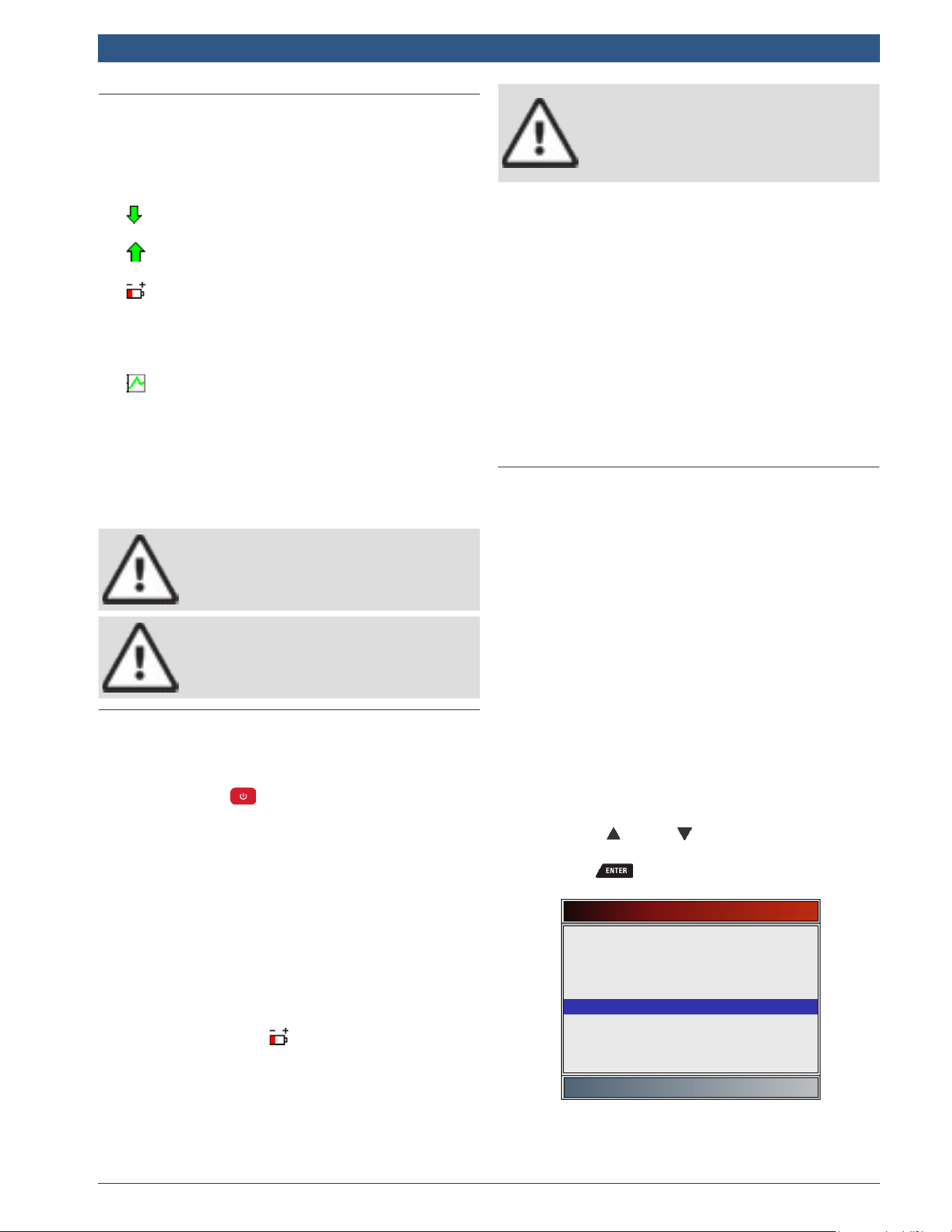
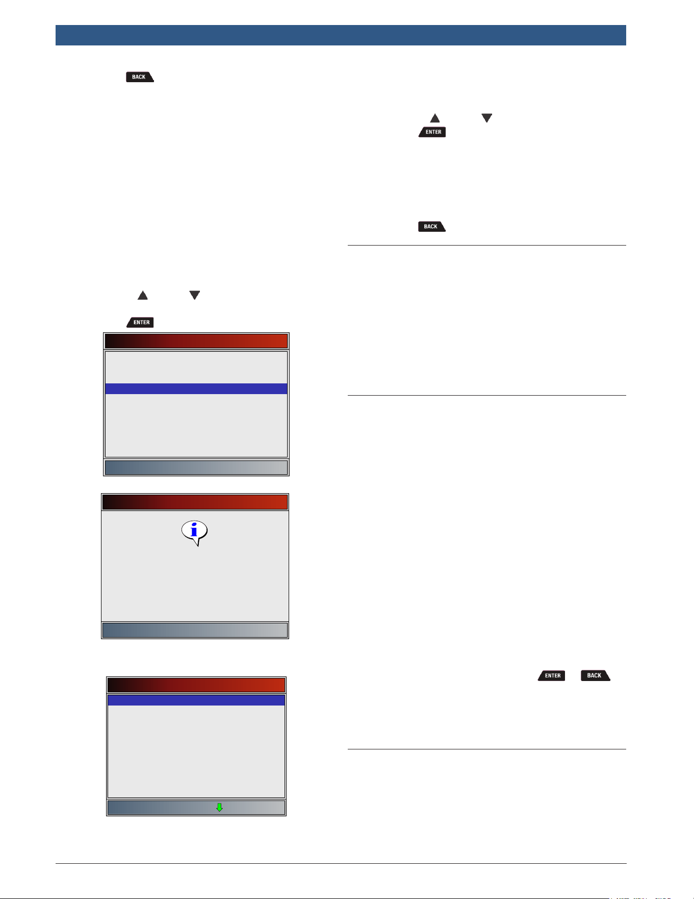
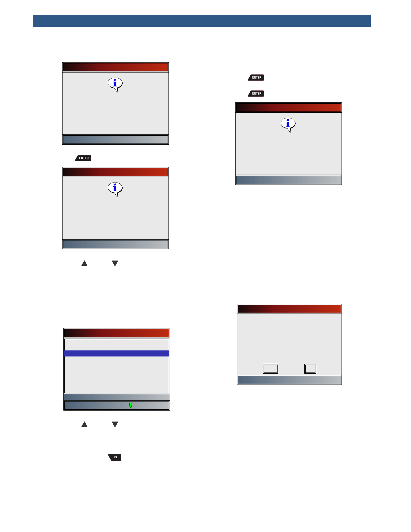
1. Select System Setup.
• Use the UP and DOWN keys until System
Setup is highlighted.
• Press .
Main Menu
HD SAE (J1708/J1587, J1939)
HD OBD (ISO 15765-4)
Global Automotive OBDII
Review Data
Print Data
System Setup
Changing Measurement Units
English is the default measurement unit. Measurement
units can be changed in View and Record Data.
en
|
12
|
User guide
| HDS 200/HDS 250
HD Scan Tool for Class 4-8 Diesel, Light and Medium Vehicles
581618 | REV. B | 11.2018
Bosch Automotive Service Solutions Inc.
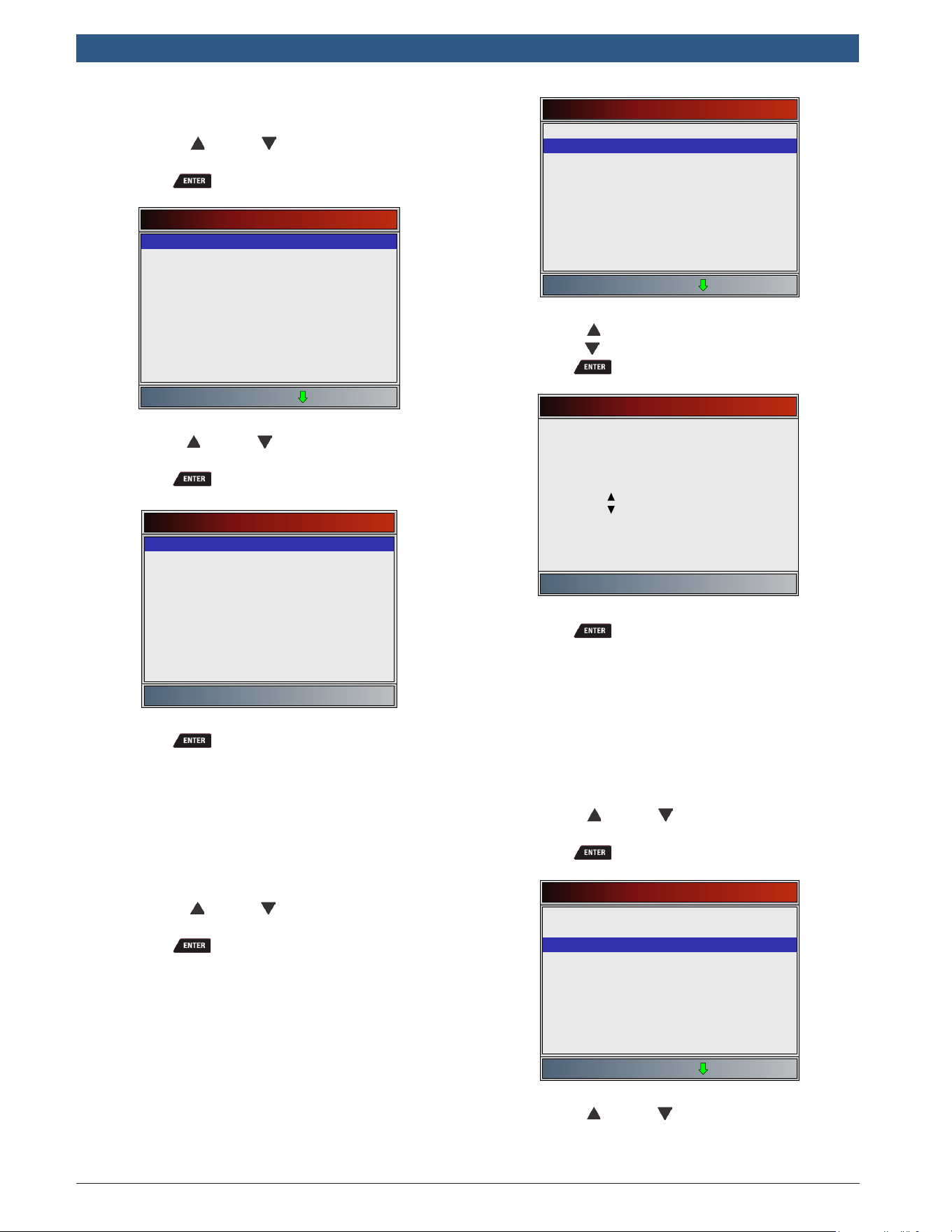
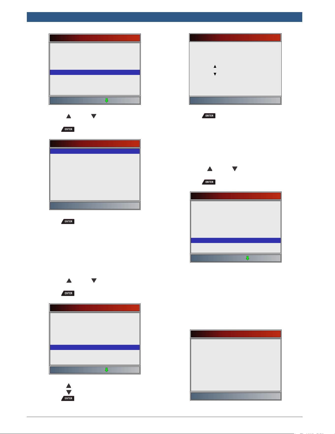
From System Setup menu:
1. Select English/Metric.
• Use the UP and DOWN keys until English/
Metric is highlighted.
• Press .
System Setup
English/Metric
Auto-Power Off
Quick Test
Print Header
Language Setup
Long PID/SPN Names
Pre-Trigger Setup
Tool Information
Display Test
2. Select desired measurement unit.
• Use the UP and DOWN keys until the
desired unit is highlighted.
• Press .
Measurement Units
English
Metric
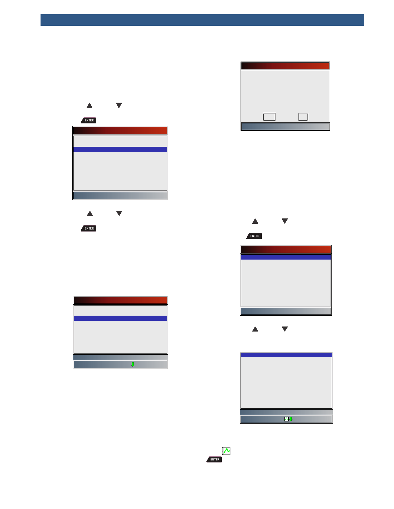
3. Save measurement setting.
• Press .
Changing Auto-Power Off
The Auto-Power Off feature allows the tool to turn off
automatically after a selected amount of time when tool
is not being used. The Auto-Power Off feature will only
turn the tool off when it is operating on battery power.
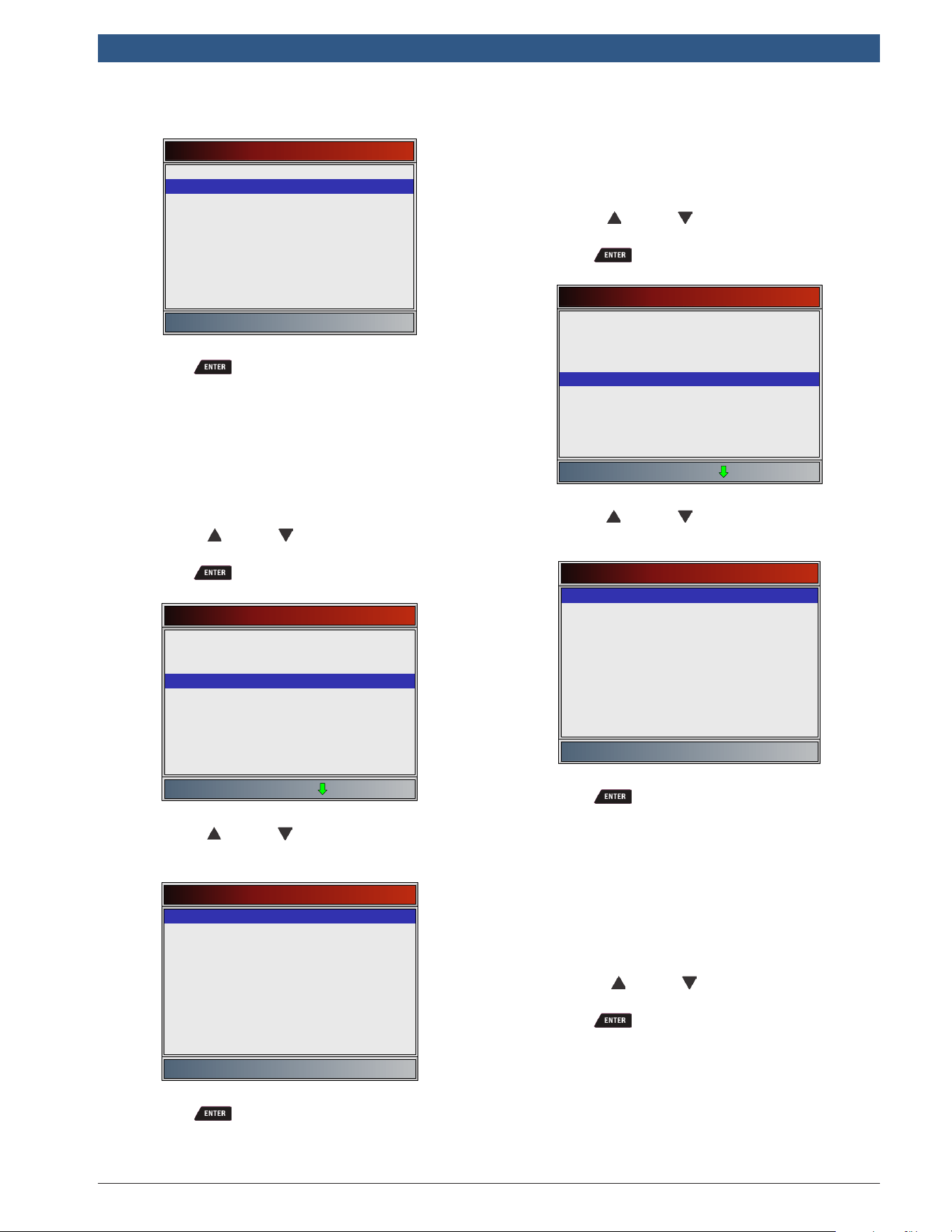
From System Setup menu:
1. Select Auto-Power Off.
• Use the UP and DOWN keys until Auto-
Power Off is highlighted.
• Press .
System Setup
English/Metric
Auto-Power Off
Quick Test
Print Header
Language Setup
Long PID/SPN Names
Pre-Trigger Setup
Tool Information
Display Test
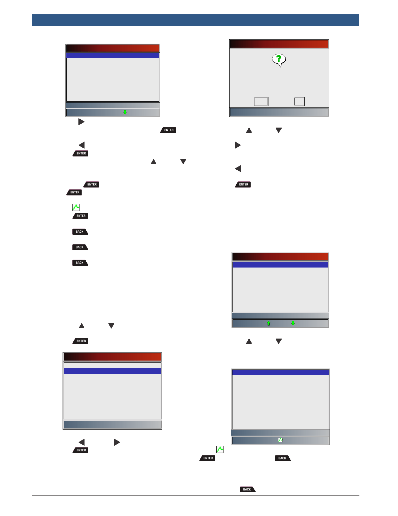
2. Increase or Decrease Auto-Power Off time.
• Use the UP key to increase time.
• Use the DOWN key to decrease time.
• Press .
Auto-Power Off
Press ENTER to continue
Increase time
2 minute(s)
Decrease time
3. Save Auto-Power Off time.
• Press .
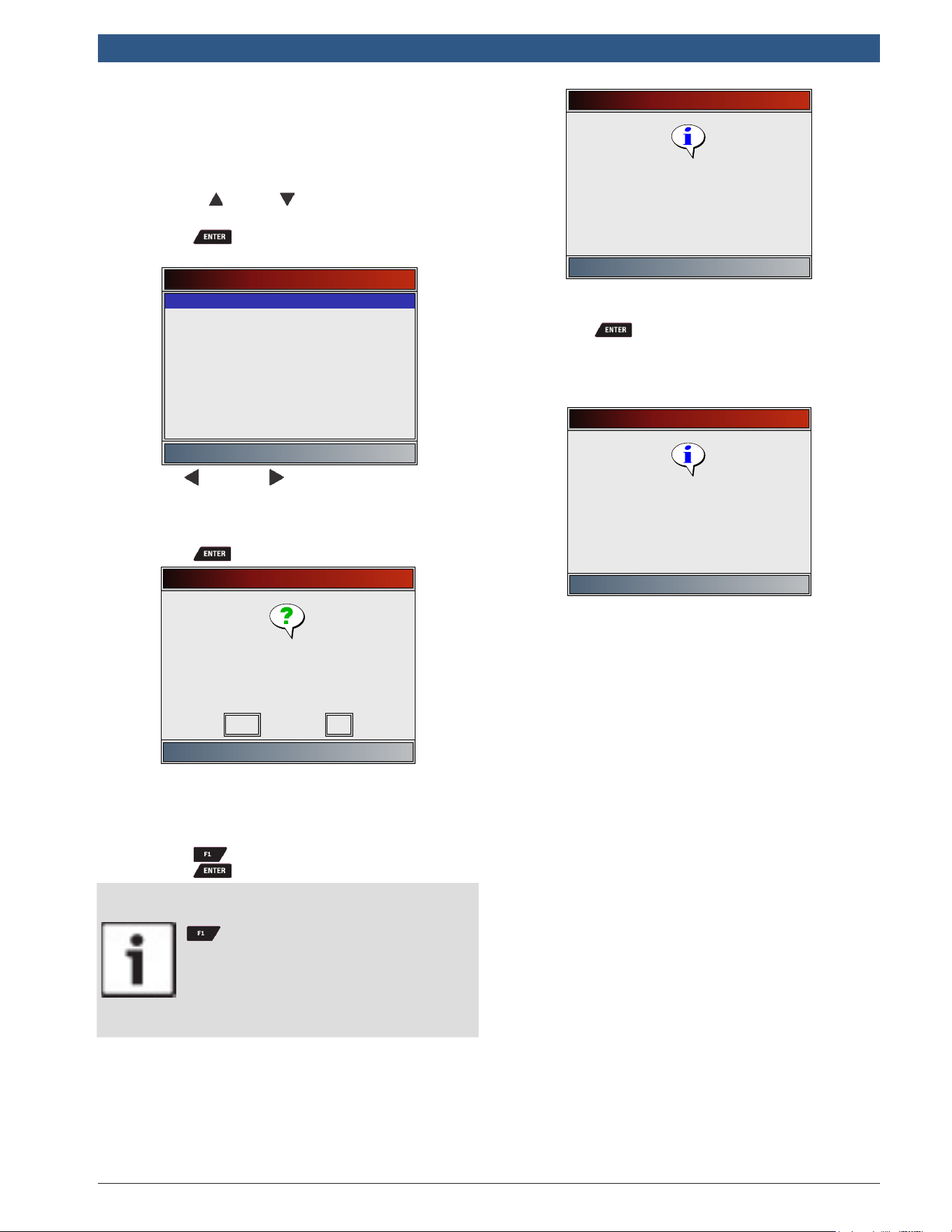
Quick Test
Quick Test is a feature of the tool that occurs the first
time the tool establishes communication with the vehi-
cle after vehicle selection. Quick Test will display the
results of I/M Monitors (Global Automotive OBDII and
HD OBDII only) and Read Codes.
From System Setup menu:
1. Select Quick Test.
• Use the UP and DOWN keys until Quick
Test is highlighted.
• Press .
System Setup
English/Metric
Auto-Power Off
Quick Test
Print Header
Language Setup
Long PID/SPN Names
Pre-Trigger Setup
Tool Information
Display Test
2. Select desired Quick Test choice.
• Use the UP and DOWN keys until desired
choice is highlighted.
581618 | REV. B | 11.2018
Bosch Automotive Service Solutions Inc.
HDS 200/HDS 250
HD Scan Tool for Class 4-8 Diesel, Light and Medium Vehicles
|
User guide | 13
|
en
• Select Read All Codes to view results of all
codes. This selection is enabled by default.
Quick Test
Disabled
Read All Codes
3. Save Quick Test setting.
• Press .
Print Header
Print Header selection allows the user to turn off the
scan tool printing the currently-selected vehicle prior to
the retrieved vehicle data when selecting items from the
Print Data menu.
From System Setup menu:
1. Select Print Header.
• Use the UP and DOWN keys until Print
Header is highlighted.
• Press .
System Setup
English/Metric
Auto-Power Off
Quick Test
Print Header
Language Setup
Long PID/SPN Names
Pre-Trigger Setup
Tool Information
Display Test
2. Select desired Print Header choice.
• Use the UP and DOWN keys until desired
choice is highlighted.
Print Header
ON
OFF
3. Save Print Header setting.
• Press .
Language Setup
Language Setup selection allows the user to change the
language used by the tool. English is the default lan-
guage.
From System Setup menu:
1. Select Language Setup.
• Use the UP and DOWN keys until Lan-
guage Setup is highlighted.
• Press .
System Setup
English/Metric
Auto-Power Off
Quick Test
Print Header
Language Setup
Long PID/SPN Names
Pre-Trigger Setup
Tool Information
Display Test
2. Select desired Language Setup choice.
• Use the UP and DOWN keys until the
desired language is highlighted.
Language Setup
English
Español
Francais
3. Save Language Setup setting.
• Press .
NOTE: When Spanish or French translation is not known,
English will be shown.
Long PID/SPN Names
Long PID/SPN Names allows the user to enable/disable
the tool scrolling the complete PID name on the bottom
line of the display while viewing Live Data or viewing
Freeze Data. From System Setup menu:
1. Select Long PID/SPN Names.
• Use the UP and DOWN keys until Long
PID/SPN Names is highlighted.
• Press .
en
|
14
|
User guide
| HDS 200/HDS 250
HD Scan Tool for Class 4-8 Diesel, Light and Medium Vehicles
581618 | REV. B | 11.2018
Bosch Automotive Service Solutions Inc.
System Setup
English/Metric
Auto-Power Off
Quick Test
Print Header
Language Setup
Long PID/SPN Names
Pre-Trigger Setup
Tool Information
Display Test
2. Select ON or OFF.
• Use the UP and DOWN keys until the
desired option is highlighted.
• Press .
Long PID/SPN Names
ON
OFF
3. Save Long PID/SPN Names setting.
• Press .
Pre-Trigger Setup
This function is used to configure how many Pre-Trigger
frames are stored prior to beginning a recording. Pre-
Trigger frames are the negative frames when you are
playing back a recording.
From System Setup screen:
1. Select Pre-Trigger Setup.
• Use the UP and DOWN keys until Pre-
Trigger Setup is highlighted.
• Press .
System Setup
English/Metric
Auto-Power Off
Quick Test
Print Header
Language Setup
Long PID/SPN Names
Pre-Trigger Setup
Tool Information
Display Test
2. Increase or Decrease Pre-Trigger Frames.
• Use the UP key to increase frames.
• Use the DOWN key to decrease frames.
• Press .
Pre-Trigger Frames
Press ENTER to continue
Increase frame
5 frame(s)
Decrease frame
3. Save Pre-Trigger frames setting.
• Press .
Tool Information
Tool Information allows the user to view specific tool infor-
mation that may be needed when contacting customer
service.
From System Setup menu:
1. Select Tool Information.
• Use the UP and DOWN keys until Tool
Information is highlighted.
• Press .
System Setup
English/Metric
Auto-Power Off
Quick Test
Print Header
Language Setup
Long PID/SPN Names
Pre-Trigger Setup
Tool Information
Display Test
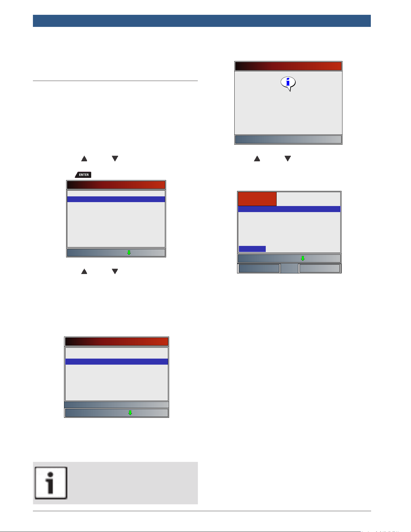
2. View information.
• Serial Number (Serial No:)
• Software ID (SW ID:)
• Hardware Version (HW Ver:)
• Boot Version (Boot Ver:)
• Product ID (Prod ID:)
• Board ID (Board ID:)
• Burn Date (Burn Date:)
• Burn Location (Burn Loc:)
Tool Information
Serial No
SW ID
HW Ver
Boot Ver
1284168
5126
01
02
Prod ID
Board ID
Burn Date
21
33
12/04/14
Burn Loc 04
3. Record Tool Information.
581618 | REV. B | 11.2018
Bosch Automotive Service Solutions Inc.
HDS 200/HDS 250
HD Scan Tool for Class 4-8 Diesel, Light and Medium Vehicles
|
User guide | 15
|
en
• Space is provided inside the front cover of this
manual to write down the scan tool information.
4. Return to System Setup menu.
• Press
or
• Press .
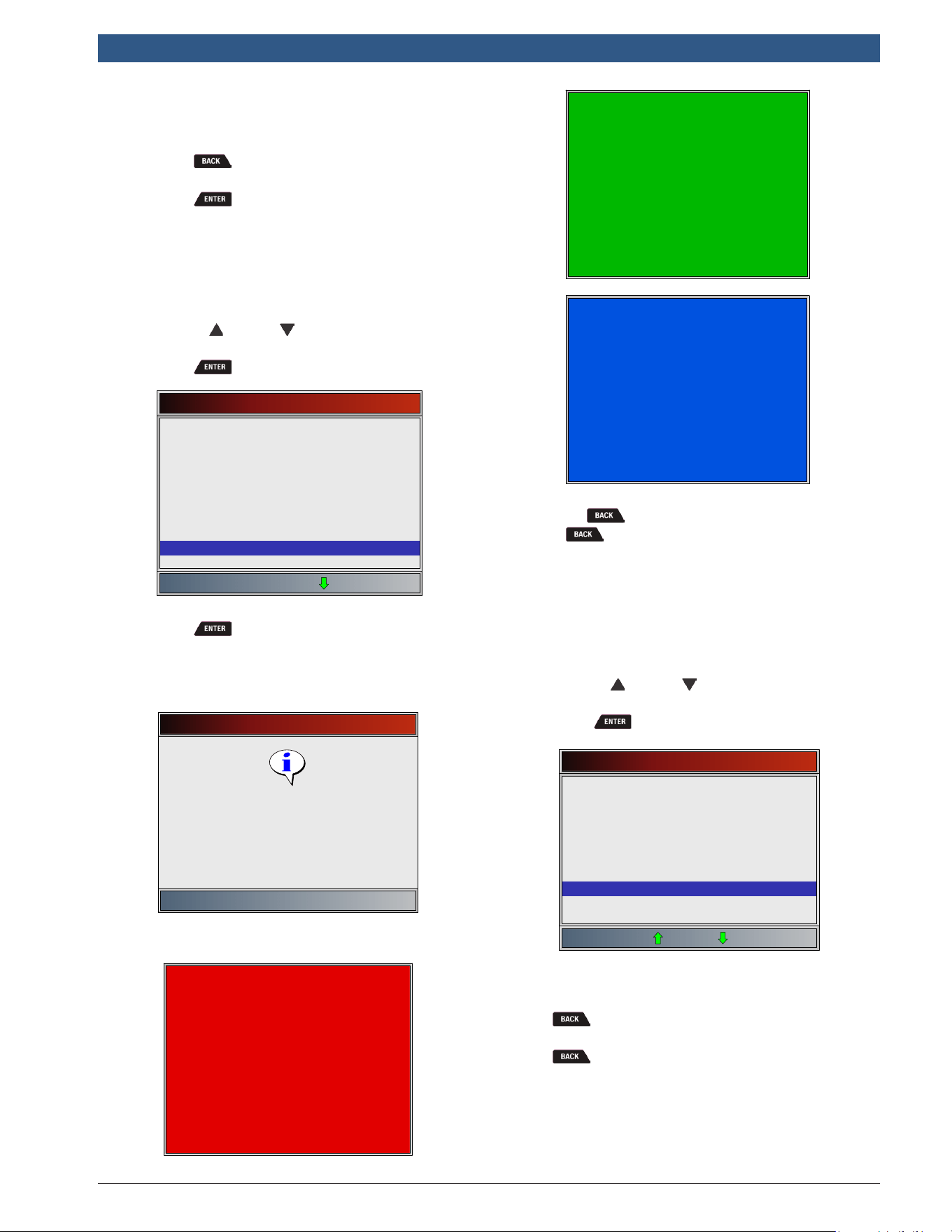
Display Test
The Display Test is used to check the display. The test fills
every pixel of the display with a solid color.
From System Setup menu:
1. Select Display Test.
• Use the UP and DOWN keys until Display
Test is highlighted.
• Press .
System Setup
English/Metric
Auto-Power Off
Quick Test
Print Header
Language Setup
Long PID/SPN Names
Pre-Trigger Setup
Tool Information
Display Test
2. Start Display Test.
• Press .
3. Look for missing spots.
• The first screen displayed says, “Check for
missing spots in the display.”
Display Test
Press BACK to exit
Check for spots in the
display
• Solid red, green, and blue screens are dis-
played.
• These four screens will continue in succession
until is pressed.
4. Press to exit the test and return to the System
Setup menu.
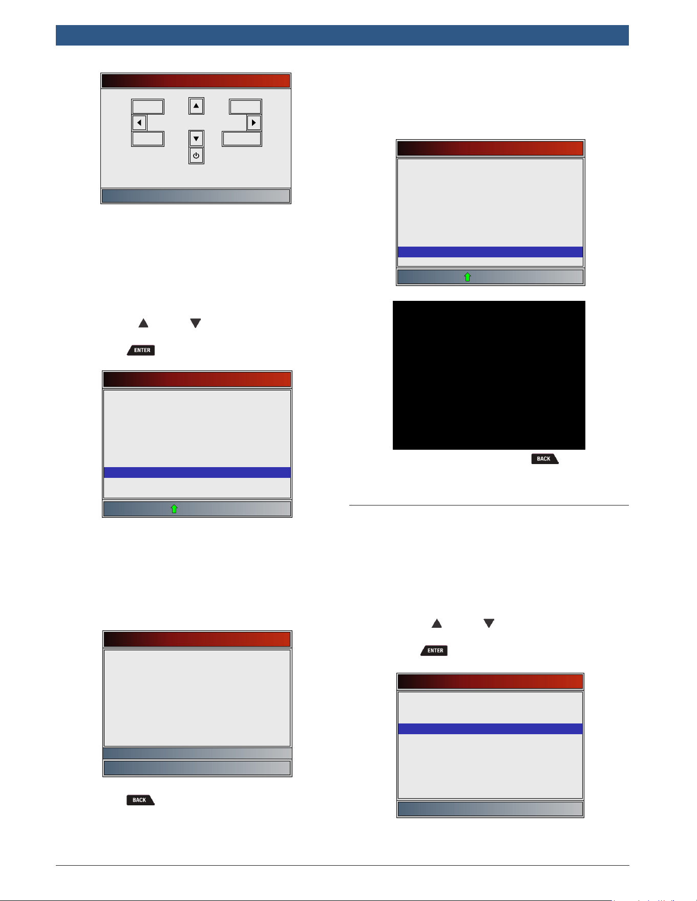
Keypad Test
The Keypad Test is used to verify that the keys are
working correctly.
From System Setup menu:
1. Select Keypad Test.
• Use the UP and DOWN keys until Keypad
Test is highlighted.
• Press .
System Setup
Quick Test
Print Header
Language Setup
Long PID/SPN Names
Pre-Trigger Setup
Tool Information
Display Test
Keypad Test
Memory Test
2. Press a key.
• Key name or scroll direction should inverse
colors on display.
• will return the tool to the System Setup
screen. If System Setup screen does not return,
is not working correctly.
en
|
16
|
User guide
| HDS 200/HDS 250
HD Scan Tool for Class 4-8 Diesel, Light and Medium Vehicles
581618 | REV. B | 11.2018
Bosch Automotive Service Solutions Inc.
Keypad Test
Press BACK to exit
BACK
ENTER
F1
F2
Memory Test
The Memory Test will test RAM and Flash ROM. Run the
Memory Test if the tool has trouble:
• Playing back recorded data.
• Displaying trouble code definitions.
From System Setup menu:
1. Select Memory Test.
• Use the UP and DOWN keys until Memory
Test is highlighted.
• Press .
System Setup
Print Header
Language Setup
Long PID/SPN Names
Pre-Trigger Setup
Tool Information
Display Test
Keypad Test
Memory Test
Program Mode
• Memory Test may take several minutes to com-
plete.
• Memory Test results display:
– If no problems were detected, then “Pass”
is displayed.
– If RAM fails, an error message is shown.
– If FLASH fails, a checksum is shown.
Memory Test
INT RAM
INT FLASH
Passed
10ca
Press BACK to exit
2. Return to System Setup menu.
• Press .
Program Mode
The Program Mode is used for updating the scan tool.
Instructions are provided with upgrades. Refer to “3.2
Download Scanning Suite” on page 7.
System Setup
Print Header
Language Setup
Long PID/SPN Names
Pre-Trigger Setup
Tool Information
Display Test
Keypad Test
Memory Test
Program Mode
PROGRAM MODE
See User Manual
Connect Tool to PC
with USB Cable
• If the Program Mode is entered, is not opera-
tional. The tool must be powered off to exit Program
Mode and then restarted to continue.
4.6 Vehicle-Specific Features
Review Data
The Review Data function allows the user to view the
information from the previous vehicle tested. The scan
tool can be powered from vehicle, battery power or PC
using USB to use the Review Data function.
1. Select Review Data.
• Use the UP and DOWN keys until Review
Data is highlighted.
• Press .
Main Menu
HD SAE (J1708/J1587, J1939)
HD OBD (ISO 15765-4)
Review Data
Global Automotive OBDII
Print Data
System Setup
2. Select item whose data you wish to review.
• The Review Data menu shows a checkmark next
to the item(s) that has data.
581618 | REV. B | 11.2018
Bosch Automotive Service Solutions Inc.
HDS 200/HDS 250
HD Scan Tool for Class 4-8 Diesel, Light and Medium Vehicles
|
User guide | 17
|
en
• If there is not a checkmark next to the item, then
this item can’t be selected until the appropriate
function is run from the Heavy Duty Standard
menu, HD OBD menu or Global Automotive
OBDII menu.
• Only one function, Recording, needs detailed
instructions.
Review Data
✓I/M Monitors
✓DTCs (Codes)
✓State OBD Check
✓Recording
View Freeze Data
✓O2 Monitor Tests
✓Diagnostic Monitor Tests
Vehicle Information
Modules Present
Recording
The Recording function is used to play back a recording.
This function is very similar to View Data. The only differ-
ence is that View Data is real-time viewing of PIDs, while
Recording is a viewing of previously recorded PIDs.
From the Review Data menu:
1. Select Recording.
• Use the UP and DOWN keys until Record-
ing is highlighted.
• The tool can keep up to 5 recordings per vehi-
cle. If the tool has more than one recording,
select the recording you wish to playback.
• Press .
2. Select Playback Recording.
• Use the UP and DOWN keys until Playback
Recording is highlighted.
• Press .
Playback Options
Playback Recording
Long PID/SPN Names
English/Metric
• The recording has frame number and timestamp
(in seconds).
– Negative frames and timestamps indicate
data recorded before trigger event.
– Positive frames and timestamps indicate
data recorded after trigger event.
– Use the UP and DOWN keys to view
recorded PID data within each frame.
– Use the LEFT and RIGHT keys to scroll
back and forth through frames.
– Refer to “8 Appendix A—Global OBD II PID
Definitions” on page 42.
– Refer to “9 Appendix B—Glossary” on page
45 for HD abbreviations.
ABSLT TPS(%)
CALC LOAD(%)
COOLANT(°F)
ENG SPEED(RPM)
FUEL SYS 1
FUEL SYS 2
IAT(°F)
IGN ADV(°)
LT FTRM1(%)
0.0
3.5
95
692
OPEN
OPEN
75
4.5
3.1
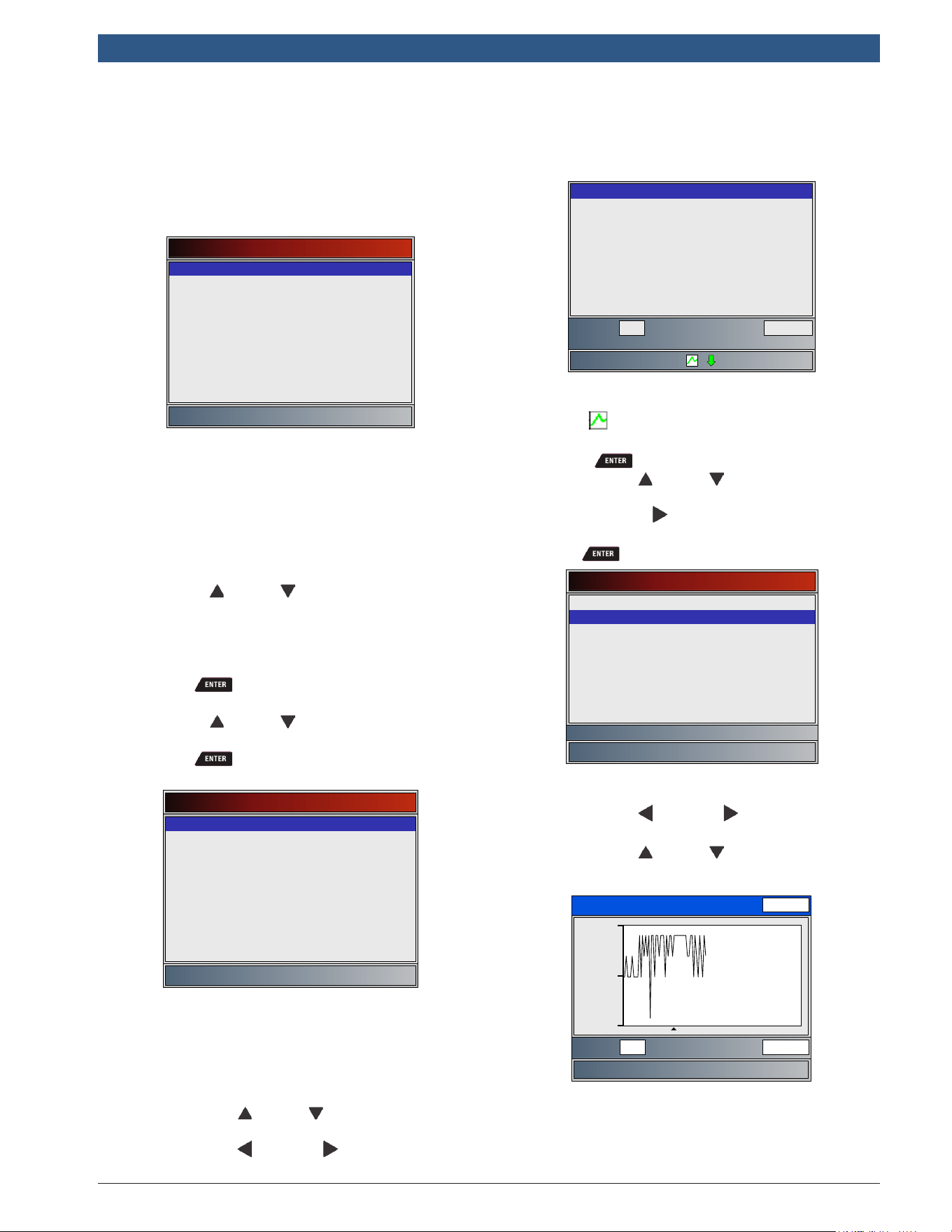
Frame:
Throttle position
Time: 0.00
– If graphing is available for selected PID, the
“ ” icon is located on the side of the
screen.
• Press to select PIDS to graph.
– Use the UP and DOWN keys to high-
light the second PID to graph and then
press the RIGHT key to select. A maxi-
mum of two PIDs can be graphed. Press
to see graph.
Select PIDs to Graph
ABSLT TPS(%)
✓CALC LOAD(%)
COOLANT(°F)
ENG SPEED(RPM)
IAT(°F)
MAF(LB/M)
MAP(”HG)
VEH SPEED(MPH)
Calculated Engine Load
• The triangle below the graph indicates the
position of the frame in the graph.
– Use the LEFT and RIGHT keys to scroll
back and forth through graph.
– Use the UP and DOWN keys to toggle
back and forth between PIDs.
CALC LOAD(%)
19.4
17.5
Frame: Time:
21 26.8
19.2
• Different vehicles communicate at different
speeds and support a different number of PIDs.
Therefore, the maximum number of frames that
can be recorded varies.
3. Return to Review Data menu.
en
|
18
|
User guide
| HDS 200/HDS 250
HD Scan Tool for Class 4-8 Diesel, Light and Medium Vehicles
581618 | REV. B | 11.2018
Bosch Automotive Service Solutions Inc.
• Press .
Print Data
The Print Data function allows the printing of diagnostic
information stored in the scan tool.
• The scan tool’s internal battery power can be
used to print data.
• Use the Print Header function to turn ON/OFF
printing vehicle information prior to printing
data.
• Make sure you have preciously installed the PC
software in Download Scanning Suite.
• Launch Scanning Suite and then start printing
application.
• Follow all instructions on PC.
1. Select Print Data.
• Use the UP and DOWN keys until Print
Data is highlighted.
• Press .
Main Menu
Vehicle Diagnostics
Acronyms
Review Data
Print Data
Code Lookup
System Setup
Print Data
Press ENTER to continue
Launch PC printing software
application.
• On the Print Data menu, Print All prints all data
collected by the scan tool.
Print Data
✓Print All
✓I/M Monitiors
✓DTCs (Codes)
State OBD Check
Recording
View Freeze Data
O2 Monitor Tests
Diagnostic Monitor Tests
Vehicle Information
• When printing a recording, Start frame and end
frame need to be defined.
• This menu contains up to 5 previous vehicles, so
select which vehicle you wish to print data.
2. Select Data To Be Printed.
• Use the UP and DOWN keys.
• Press .
• The Print Data menu shows a checkmark next to
the items that have data.
• If there isn’t a checkmark next to the item, then
this item can’t be selected until the appropriate
function is run from the Diagnostic Menu.
3. Return to Select Print Data screen.
• Press .
4.7 Locating Data Link Connector
• The Data Link Connector (DLC) is usually located
under the driver’s side dash for OBD II Vehicles,
Deutsch 6-pin, and Deutsch 9-pin HD Vehicles.
• For more information on OBD II DLC locations, go to
http://www.obdclearinghouse.com.
NOTE: When using the OBD II, 9-pin, or 6-pin cables,
power to the tool generally comes from the vehicle. If
the tool does not power-up, use the cigarette cable to
power-up the tool.
4.8 Connect the Tool
1. Connect extension cable to the tool.
2. Connect the appropriate data link cable to the exten-
sion cable. This can either be the J1962 Type B cable,
Deutsch 6-pin cable, or the Deutsch 9-pin cable
depending on the vehicle. Only use the cables
included in your kit.
3. Connect data link connector to vehicle.
4. The scan tool should power up. If the tool does not
power up, make sure the cable is connected securely.
5. Connect cigarette lighter cable if the scan tool did
not power up.
6. Place ignition key in the ON position and have the
engine OFF.
7. Select HD SAE (J1708/J1587, J1939), HD OBD (ISO
15765-4) or Global Automotive OBDII from the Main
Menu.
8. The required cables screen identifies which DLC
cables to use for your selection.
9. If Quick Test is enabled, the Scan Tool runs the Quick
Test and displays the results. Press or .
10. The Scan Tool shows Diagnostic Menu.
IMPORTANT: Make sure you have correctly selected your
vehicle. Incorrect vehicle identification can produce
unexpected test results.
4.9 Vehicle Selection
From the Main Menu select the vehicle to diagnose.
Select HD SAE (J1708/J1587, J1939) if the truck vehi-
cle supports either J1708/J1587, J1939. Select HD OBD
(ISO 15765-4) if the truck supports ISO 15765-4 using
the J1962 connector. Select Global Automotive OBDII if
the vehicle supports OBDII as identified on the Vehicle
581618 | REV. B | 11.2018
Bosch Automotive Service Solutions Inc.
HDS 200/HDS 250
HD Scan Tool for Class 4-8 Diesel, Light and Medium Vehicles
|
User guide | 19
|
en
Emissions Control Information decal located under the
vehicles hood.
From the Main Menu:
1. Select HD SAE (J1708/J1587, J1939), HD OBD
(ISO 15765-4) or Global Automotive OBDII.
• Use the UP and DOWN keys until HD SAE
(J1708/J1587, J1939) is highlighted.
• Press .
Main Menu
HD SAE (J1708/J1587, J1939)
HD OBD (ISO 15765-4)
Global Automotive OBDII
Review Data
Print Data
System Setup
2. Use the LEFT and RIGHT keys to select Yes.
• The scan tool keeps diagnostic data for only
the last vehicle. This data is cleared by select-
ing Yes.
• Press .
Heavy Duty Standard
This selection requires
clearing of diagnostic data
for the previous vehicle.
Do you want to continue?
No
Yes
3. Make sure the proper diagnostic cable is connected
per screen instructions.
• Confirm proper scan tool cable part number is
connected.
• Press F1 to toggle Demo mode on or off.
• Press .
IMPORTANT
To display demonstration data, press the
F1 key. A checkmark in the demo
button indicates Demo function is on.
Press the key again to turn the function
off. When in demo mode, the scan tool
doesn’t communicate with a vehicle but
will instead display demonstration data.
4. A Turn Key Off screen will display.
Turn Key Off
Press ENTER to continue
Please turn the key off for
10 seconds then turn the key
on.
• Turn key off for 10 seconds.
• Turn key on.
• Press .
• If vehicle power is not detected, a screen is
shown to verify tool connection (non-demo
mode).
Vehicle Required
Press ENTER to continue
Please verify the tool is
connected to the vehicle with
the ignition key turned on.
5 Heavy Duty Standard Diag-
nostics
Heavy Duty Standard Diagnostics is available by select-
ing Heavy Duty Standard from the Main Menu. This
section applies to all heavy duty SAE J1708/J1587 &
J1939 compliant vehicles.
The first time the scan tool links to the vehicle, the
communication protocol is automatically detected, and
is used until the scan tool is turned off or another vehi-
cle is diagnosed.
If an error message displays, make sure the scan tool
connector is attached and the ignition key is on. Cycle
ignition key to OFF for 10 seconds, then ON. This may be
required to reset computer. If required, select YES to try
again. If problem still exists, “7.1 Error Messages” on
page 41.
The scan tool keeps data received from the previous
vehicle selected until any of the following occurs:
• A new vehicle is selected.
• Scan tool is flash programmed to update software.
The Heavy Duty Standard Menu has the following selec-
tions:
• Read Codes
• Erase Codes
• View Data
• Record Data
• Module Information
en
|
20
|
User guide
| HDS 200/HDS 250
HD Scan Tool for Class 4-8 Diesel, Light and Medium Vehicles
581618 | REV. B | 11.2018
Bosch Automotive Service Solutions Inc.
• Vehicle Information
• Review Data
• Print Data
• System Setup
5.1 Read Codes
The Read Codes function allows the scan tool to read
the DTCs from the vehicle’s control modules. DTCs are
used to help determine the cause of a problem or prob-
lems with a vehicle.
Read Codes can be done with the key on engine off
(KOEO) or with the key on engine running (KOER).
From the Heavy Duty Standard menu:
1. Select Read Codes.
• Use the UP and DOWN keys until Read
Codes is highlighted.
• Press .
Global Automotive OBDII
Read Codes
I/M Monitors
Erase Codes
MIL Status
State OBD Check
View Data
Record Data
View Freeze Data
Drive Cycle Monitor
2. A module menu is displayed.
• Use the UP and DOWN keys until the
designed choice is highlighted.
• The menu is divided into two sections: a J1587
Module section and a J1939 Module section.
• The bottom line displays information for the
highlighted module: Protocol, module address
(Module Identifier=MID and Source Address =
SA) and full module description.
Select Module
J1587 MID: 128 Engine #1
Transmission
Engine #1
J1939 Modules
Engine #1
Transmission #1
J1587 Modules
All Listed Modules
• If All Listed Modules is selected from the Select
Module menu, all of the codes will be displayed
as if all menu items were selected individually.
– If DTCs are present, a message displays
identifying the DTC definition source.
IMPORTANT
Code definitions are defined by SAE
J1587 & J1939. OEM definitions may dif-
fer. Please refer to OEM Service
Manuals for confirmation.
– If no DTCs are present, a message stating
“No codes found” is displayed.
Read Codes
Press ENTER to continue
No codes found
3. View and write down the DTCs.
• Use the UP and DOWN keys to scroll thru
all DTCs.
This screen indicates where the Read Codes information
is located.
DTC Description,
FMI Description
Count: #DTC Type
X/Y
module: #
DTC:#
FMI:#
EraseLamp Status
Module Name
• DTC # - Number of the trouble code found. For
J1587 modules, this will either be SID for Subsys-
tem Identification or PID for Parameter Identifica-
tion. For J1939 modules, this will be SPN for Sus-
pect Parameter Number.
• FMI # - Number of the Failure Mode Identifier.
• X/Y - Indication that code x of y is being viewed
where x is the code being viewed of the total y.
• module: # - Address of module reporting DTC. For
J1587 modules, this will be MID for Module Identi-
fier. For J1939 modules, this will be SA for Source
Address.
• Module Name - description of the module.
• DTC Description - This area is reserved for the text
description of the DTC #. It is either the description
for the SPN, SID or PID depending on the module
selected and the trouble code.
• FMI Description - This is appended to the DTC
description and is the description of the Failure
Mode Indicator.
• DTC Type - This area is reserved for providing addi-
tional information about the DTC. If Active, the DTC
was occurring at the time of scan tool request. If
Inactive, the DTC was not occurring at the time of
the request.
• Count # - This field is optional. This is the number of
occurrences this DTC has been detected.
Examples of Read Codes information screens follow.
581618 | REV. B | 11.2018
Bosch Automotive Service Solutions Inc.
HDS 200/HDS 250
HD Scan Tool for Class 4-8 Diesel, Light and Medium Vehicles
|
User guide | 21
|
en
In this example, the J1587 Engine #1 module, Module
Identifier (MID) 128 is reporting a DTC. It was Active at
the time DTCs were read.
Injector Cylinder #6 - Data erratic,
intermittent, or incorrect
ACTIVE
1/6
MID: 128
SID:6
FMI:2
EraseLamp Status
Engine #1
In this example, the J1939 Engine #1 module, Source
Address (SA) 0 is reporting a DTC. It was Active at the
time DTCs were read. This specific SPN/FMI has only
occurred one time.
Accelerator Pedal Position 1 - Voltage
Below Normal, Or Shorted To Low Source
Count: 1ACTIVE
1/23
SA: 0
SID:91
FMI:4
EraseLamp Status
Engine #1
Lamp Status
Press the F1 key while viewing a DTC to show the
Lamp status for the module of the given DTC. Details of
all possible Lamps is shown.
Lamp Status
MIL:
Red Stop:
Amber Warning:
Protect:
Unavailable
On
Off
Off
To return to the last DTC being reviewed, press .
Erase
Press the F2 key while viewing a DTC to jump to the
Erase Codes screen. The distinction between erasing
codes by pressing F2 from Read Codes or selecting
Erase Codes from the Heavy Duty Standard menu is
that you can erase a specific DTC when starting from
Read Codes. The DTC shown when the F2 key is pressed
can be erased. See “5.2 Erase Codes” on page 21.
5.2 Erase Codes
The Erase Codes function deletes DTCs from vehicle’s
control module(s). Perform this function key on engine
off (KOEO). Do not start the engine.
The Erase Codes function may also erase diagnostic
information pertaining to the specified DTC. Perform
Erase Codes function only after systems have been
checked completely and DTCs have been written down.
After servicing the vehicle, erase stored DTCs and verify
no codes have returned. If a DTC returns, problem has
not been fixed or other faults are present.
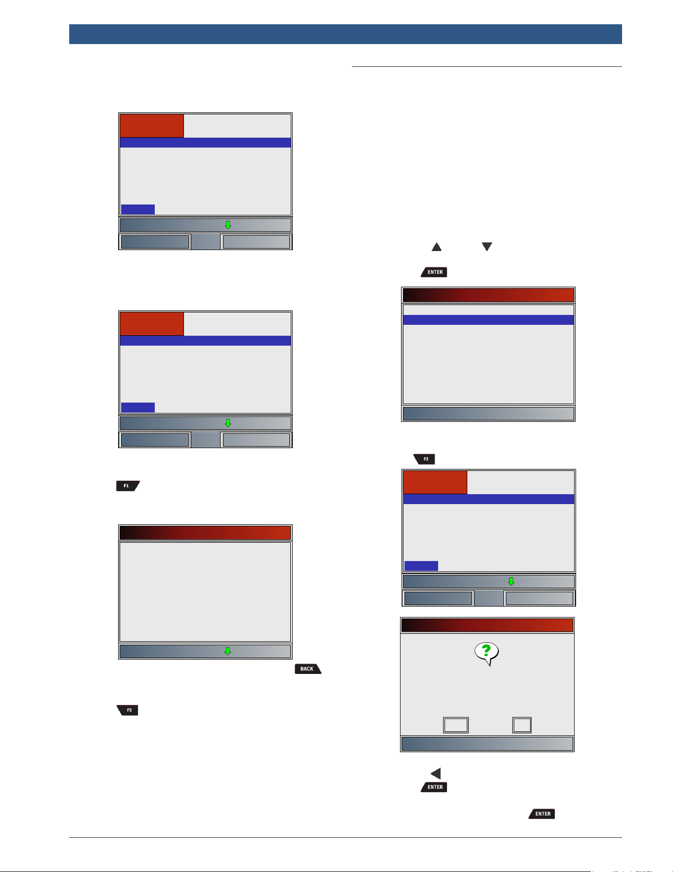
From Heavy Duty Standard menu:
1. a. Select Erase Codes.
• Use the UP and DOWN keys until Erase
Codes is highlighted.
• Press .
Heavy Duty Standard
Read Codes
Erase Codes
View Data
Record Data
Module Information
Vehicle Information
Review Data
Print Data
System Setup
OR
From Read Codes DTC Description screen:
1. b. Press F2, Erase.
Accelerator Pedal Position 1 - Voltage
Below Normal, Or Shorted To Low Source
Count: 1ACTIVE
1/23
SA: 0
SID:91
FMI:4
EraseLamp Status
Engine #1
Erase Codes
Are you sure you want to
erase diagnostic results and
codes?
No
Yes
2. Select YES to erase diagnostic results and codes.
• Use the LEFT arrow key.
• Press .
• If diagnostic results and codes are not to be
erased select NO and press .
en
|
22
|
User guide
| HDS 200/HDS 250
HD Scan Tool for Class 4-8 Diesel, Light and Medium Vehicles
581618 | REV. B | 11.2018
Bosch Automotive Service Solutions Inc.
• Selecting NO displays a “Command cancelled”
message.
Erase Codes
Press ENTER to continue
Command canceled
3. Turn the key on with the engine off.
• Press .
Erase Codes
Press ENTER to continue
Turn key on with engine off.
4. A module menu is displayed.
• Use the UP and DOWN keys until the
designed choice is highlighted.
• The menu is divided into two sections, a J1587
Module section and a J1939 Module section.
• The bottom line displays information for the
highlighted module: Protocol, module address
(Module Identifier=MID and Source Address =
SA) and full module description.
Select Module
J1587 MID: 128 Engine #1
Transmission
Engine #1
J1939 Modules
Engine #1
Transmission #1
J1587 Modules
All Listed Modules
5. An erase menu is displayed.
• Use the UP and DOWN keys until the
desired erase operation is highlighted.
• Select Erase Specific Code (#) to erase only the
specific code #. This menu option is only avail-
able by pressing F2 from the Read Codes
DTC Description Screen, not when selecting
Erase Codes from the Heavy Duty Standard
menu.
• Select Erase All Codes to erase all Active and
Inactive codes for the selected module.
• Select Erase Inactive Codes to erase only Inac-
tive codes for the selected module.
• Select Erase Active Codes to erase only Active
codes for the selected module.
• Press .
6. Observe the “Command sent” message is displayed.
• Press .
Erase Codes
Press ENTER to continue
Command sent
Codes remaining:0
7. The Scan Tool may not be able to confirm codes
were erased. This is true in the following cases:
• The selected module didn’t respond to a code
request after erasing (to confirm codes were
erased).
• At least one code was read from the controller
after erasing.
• The module failed to respond to a request to
erase codes.
In each of these cases, codes may not have been erased.
It may be possible to erase codes if a Global erase is sent
to all modules. However, this may erase codes from every
module.
In these cases, the Scan Tool displays:
Not All Codes Erased
To erase codes from the
selected module, it may be
necessary to send an erase to
all modules.
Warning: This may erase DTCs on
every module.
Do you want to continue?
No
Yes
• Select Yes to attempt to erase codes from every
module.
• Select No to skip.
5.3 View Data
The View Data function allows real time viewing of the
vehicle’s computer module’s parameter identification
(PID) data. As the computer monitors the vehicle, infor-
mation is simultaneously transmitted to scan tool.
View Data allows the following items to be viewed on
the scan tool:
• Sensor data
• Operation of switches
• Operation of solenoids
• Operation of relays
581618 | REV. B | 11.2018
Bosch Automotive Service Solutions Inc.
HDS 200/HDS 250
HD Scan Tool for Class 4-8 Diesel, Light and Medium Vehicles
|
User guide | 23
|
en
View Data can be shown as:
• Entire Data List
• Custom Data List
Apart from Read Codes, View Data is the most useful
diagnostic function for isolating the cause of a vehicle
operation problem.
From Heavy Duty Standard menu:
1. Select View Data.
• Use the UP and DOWN keys until View
Data is highlighted.
• Press .
Heavy Duty Standard
Read Codes
View Data
Erase Codes
Record Data
Module Information
Vehicle Information
Review Data
Print Data
System Setup
2. A module menu is displayed.
• Use the UP and DOWN keys until the
designed choice is highlighted.
• Press .
• The menu is divided into two sections, a J1587
Module section and a J1939 Module section
depending on the modules supported (if avail-
able).
• The bottom line displays information for the
highlighted module: Protocol, module address
(Module Identifier=MID and Source Address =
SA) and full module description.
Select Module
J1587 MID: 128 Engine #1
Transmission
Engine #1
J1939 Modules
Engine #1
Transmission #1
J1587 Modules
All Listed Modules
3. The Scan Tool identifies available data items (PIDs
or SPNs) to view. There are two identification meth-
ods:
• The quick method: The Scan Tool can take
approximately 15 seconds to identify available
PIDs/SPNs. It may not get every or any available
PIDs/SPNs.
• The long method: The Scan Tool could take up
to 2 minutes to identify available PIDs/SPNs.
This method is more thorough and will identify
more PIDs/SPNs to view.
If you are not prompted with the following screen, then
the Scan Tool has completed identifying all PIDs/SPNs
supported using the long method.
On the Screen below, select “No” to perform the quick
methor or select “Yes” to perform the long method.
View Data
Discover More SPNs?
This may take several minutes.
No
Yes
4. Observe while the scan tool validates PID MAP.
• PID MAP validation is the tool asking the vehicle
which PIDs are supported. Refer to “9
Appendix B—Glossary” on page 45 for abbre-
viations.
View Entire List
View Entire List shows all supported PID data for the
vehicle being tested.
From Select Data to View menu:
1. Select Entire Data List.
• Use the UP and DOWN keys until Entire
Data List is highlighted.
• Press .
Select Data to View
Entire Data List
Custom Data List
Long PID/SPN Names
English/Metric
2. View PIDs on scan tool.
• Use the UP and DOWN keys.
• Refer to “9 Appendix B—Glossary” on page
45.
Eng ECU Temp(°F)
Est Perc Fan Spd(%)
EGR Valve #1 Pos(%)
PctAccelPedalPos3(%)
Throt Pos (%)
Eng Intercool Temp(°F)
Road Spd (mph)
Pct Eng Load (%)
Eng Clnt Temp(°F)
Brake Sys AirPressEmg
67.50
29.60
37.50
15.20
31.20
86.00
34.01
45.50
86.00
ON
ENGINE ECU TEMPERATURE
Brake Sys AirPressPri
Brake Sys AirPressSec OFF
OFF
If Long PID/SPN Names is turned ON, the expanded text
for the PID will scroll on the bottom line of display. Refer
to “Long PID/SPN Names” on page 13.
If the icon displays while a PID is selected, press
to select PIDs to graph. A maximum of 2 PIDs can
be graphed.
en
|
24
|
User guide
| HDS 200/HDS 250
HD Scan Tool for Class 4-8 Diesel, Light and Medium Vehicles
581618 | REV. B | 11.2018
Bosch Automotive Service Solutions Inc.
Select PIDs to Graph
✓Eng ECU Temp(°F)
Est Perc Fan Spd(%)
EGR Valve #1 Pos(%)
PctAccelPedalPos3(%)
Throt Pos (%)
Eng Intercool Temp(°F)
Road Spd (mph)
Pct Eng Load (%)
ENGINE ECU TEMPERATURE
Eng Clnt Temp(°F)
Brake Sys AirPressEmg
✓Eng ECU Temp(°F)
Est Perc Fan Spd(%)
EGR Valve #1 Pos(%)
PctAccelPedalPos3(%)
Throt Pos (%)
Eng Intercool Temp(°F)
Road Spd (mph)
Pct Eng Load (%)
Eng Clnt Temp(°F)
Brake Sys AirPressEmg
Brake Sys AirPressPri
Brake Sys AirPressSec
• Use the RIGHT arrow key to select/deselect
PIDs. The highlighted PID from when was
pressed is already selected
• Use the LEFT arrow key to deselect all PIDs.
• Press to view graph of selected PIDs.
• When graphing two PIDs, use the UP and
DOWN keys to highlight the desired PID, which
will also display the appropriate scale.
• Press the key to pause the graph. Press
the key again to continue graphing.
• If the icon displays while a PID is selected
press to view graph.
3. Return to PID screen.
• Press .
4. Return to Select Data to View menu.
• Press .
5. Return to Heavy Duty Standard menu.
• Press .
Custom List Select
The Custom Data List allows certain PIDs from the View
Entire Data List, such as those PIDs that apply to a
specific driveability symptom or system, to be selected.
From Select Data to View menu:
1. Select Custom List Select.
• Use the UP and DOWN keys until Custom
Data List is highlighted.
• Press .
Select Data to View
Entire Data List
Custom Data List
Long PID/SPN Names
English/Metric
2. Select View Instructions or Not.
• Use the LEFT and RIGHT keys.
• Press .
Custom Setup
Do you want to view
instructions for creating a
custom data list?
No
Yes
3. Select PIDs to View.
• Use the UP and DOWN keys to move up
and down list.
• The RIGHT arrow selects or deselects data
parameter. All selected data values are marked
with a √ symbol.
• The LEFT arrow deselects all marked data
parameters.
• The key starts recording data or display-
ing selected data parameters.
• If Long PID/SPN Names is turn ON, the
expanded text for the PID will scroll on the
bottom line of display. Refer to “Long PID/SPN
Names” on page 13.
• Selected PIDs are kept until you exit View Data
and return to the Heavy Duty Standard menu.
Select Custom List
MIL STATUS
O2S11(V)
O2S12(V)
O2S21(V)
O2S22(V)
OBD2 STAT
PTO STATUS
ST FTRM11(%)
Malfunction Indicator Lamp Statu
4. View PIDs on scan tool.
• Use the UP and DOWN arrow key.
• Refer to “9 Appendix B—Glossary” on page
45.
ABS TPS B(%)
MIL STATUS
0.0
Off
Throttle Position B
If the icon displays while a PID is selected, press
to view graph. Press to return to PID Screen.
Refer to”View Entire List” on page 32 for instructions
on how to select PIDs to graph and how to view graph.
5. Return to Select Data to View Menu.
• Press .
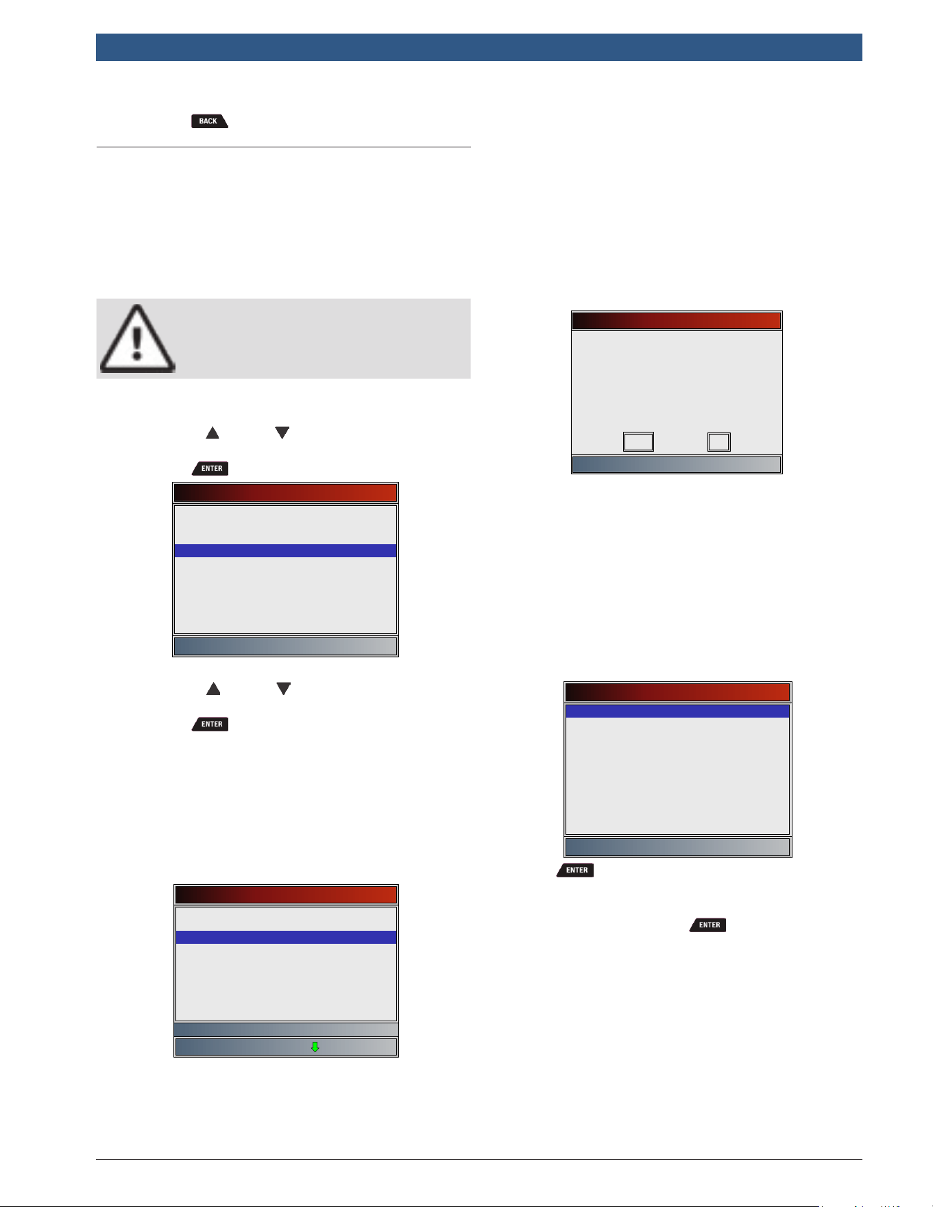
581618 | REV. B | 11.2018
Bosch Automotive Service Solutions Inc.
HDS 200/HDS 250
HD Scan Tool for Class 4-8 Diesel, Light and Medium Vehicles
|
User guide | 25
|
en
6. Return to Heavy Duty Standard menu.
• Press .
5.4 Record Data
The Record Data function records PIDs while vehicle is
parked or being driven. The Record Data function is
mainly used for diagnosing intermittent driveability
problems that cannot be isolated by any other method.
The recording time varies. A recording consists of frames
of data before the trigger and several frames after the
trigger.
CAUTION
Two people must be in vehicle when driv-
ing. One to drive and the other to operate
the scan tool.
From Heavy Duty Standard menu:
1. Select Record Data.
• Use the UP and DOWN keys until Record
Data is highlighted.
• Press .
Heavy Duty Standard
Read Codes
Record Data
View Data
Module Information
Erase Codes
Vehicle Information
Review Data
Print Data
System Setup
2. A module menu is displayed.
• Use the UP and DOWN keys until the
designed choice is highlighted.
• Press .
• The menu is divided into two sections, a J1587
Module section and a J1939 Module section
depending on the modules supported (if avail-
able).
• The bottom line displays information for the
highlighted module: Protocol, module address
(Module Identifier=MID and Source Address =
SA) and full module description.
Select Module
J1587 MID: 128 Engine #1
Transmission
Engine #1
J1939 Modules
Engine #1
Transmission #1
J1587 Modules
All Listed Modules
3. The Scan Tool identifies available data items (PIDs
or SPNs) to view. There are two identification meth-
ods:
• The quick method: The Scan Tool can take
approximately 15 seconds to identify available
PIDs/SPNs. It may not get every or any available
PIDs/SPNs.
• The long method: The Scan Tool could take up
to 2 minutes to identify available PIDs/SPNs.
This method is more thorough and will identify
more PIDs/SPNs to view.
If you are not prompted with the following screen, then
the Scan Tool has completed identifying all PIDs/SPNs
supported using the long method.
On the Screen below, select “No” to perform the quick
methor or select “Yes” to perform the long method.
Record Data
Discover More SPNs?
This may take several minutes.
No
Yes
4. Follow all instructions on display.
• The scan tool can maintain 5 recordings per
vehicle. If there are already 5 recordings stored,
the scan tool will ask which recording to over-
write.
• Scan tool validates PIDs from vehicle.
5. Refer to “5.3 View Data” on page 22 to
setup Custom List or View Entire List and Pre-Trig-
ger Setup to set the number of frames to keep prior
to triggering the recording.
Select Data to Record
Entire Data List
Custom Data List
Long PID/SPN Names
English/Metric
6. Press to begin recording.
• Data continues to be saved until either:
– Record memory is full.
– Operator presses .
• Scan tool recording times vary. A recording
consists of frames of data before trigger and
several frames after trigger.
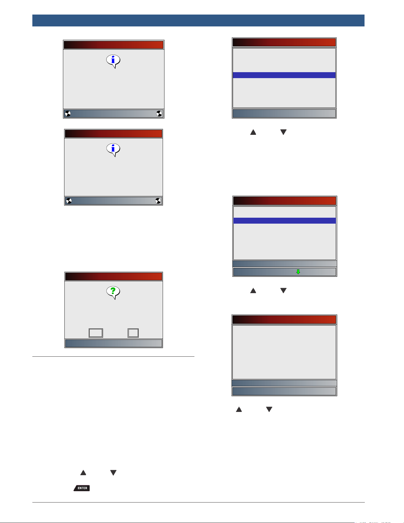
en
|
26
|
User guide
| HDS 200/HDS 250
HD Scan Tool for Class 4-8 Diesel, Light and Medium Vehicles
581618 | REV. B | 11.2018
Bosch Automotive Service Solutions Inc.
Recording
Press ENTER to trigger
recording
Collecting pretrigger data
Recording
Press ENTER to end recording
Collecting data for frame #4
7. After recording, scan tool displays a prompt to
Playback Data.
• Select NO to return to Heavy Duty Standard
menu.
• Select YES to display recorded data.
• Refer to”Recording” on page 17 for instruc-
tions on how to play back data.
Record Data
Playback data?
No
Yes
5.5 Module Information
The Module Information function allows the scan tool to
request information from modules on the vehicle. Infor-
mation collected includes Make, Module, Serial Number,
Power Unit, ECU Part Number, ECU Serial Number, ECU
Location, ECU Type, ECU Manufacturer Name, ECU
Hardware ID, Software Identifier, CVN ID, Calibration ID,
Vehicle Distance, Trip Distance, Total Vehicle Hours, &
VIN. A typical module may support some but not all of
this information.
The scan tool cannot verify if data is correct for scanned
modules.
From Heavy Duty Standard menu:
1. Select Module Information.
• Use the UP and DOWN keys until Module
Information is highlighted.
• Press .
Heavy Duty Standard
Read Codes
Module Information
View Data
Record Data
Erase Codes
Vehicle Information
Review Data
Print Data
System Setup
2. A module menu is displayed.
• Use the UP and DOWN keys until the
designed choice is highlighted.
• The menu is divided into two sections, a J1587
Module section and a J1939 Module section.
• The bottom line displays information for the
highlighted module: Protocol, module address
(Module Identifier=MID and Source Address =
SA) and full module description.
Select Module
J1587 MID: 128 Engine #1
Transmission
Engine #1
J1939 Modules
Engine #1
Transmission #1
J1587 Modules
All Listed Modules
3. View information supported by vehicle.
• Use the UP and DOWN keys (if required).
In this example, the Brake, Power Unit module returned
data.
Module Information
Brakes, Power Unit
**BNDWS
Model
EC-30 JI
Serial Number
F43080
Software ID
Make
BW-362-CD R07
In this example, the Engine #1 module returned data.
Use the UP and DOWN keys to view all the infor-
mation.
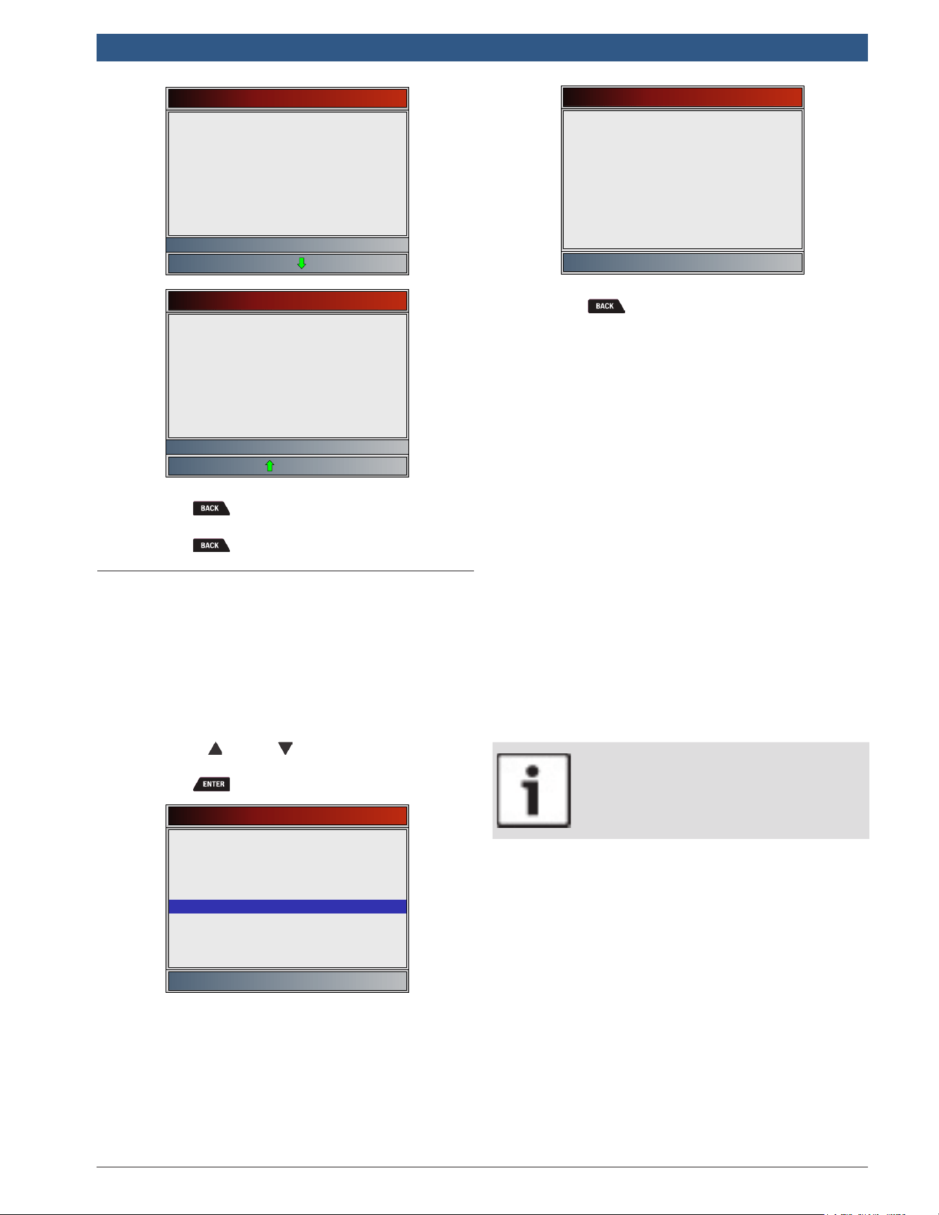
581618 | REV. B | 11.2018
Bosch Automotive Service Solutions Inc.
HDS 200/HDS 250
HD Scan Tool for Class 4-8 Diesel, Light and Medium Vehicles
|
User guide | 27
|
en
Module Information
Engine #1
INT
Model
390224241011696M10 CARB ESS
EXEMPT
Serial Number
6.5HM2Y5303951 *
VIN
Make
1HTJTSKL6BH449799
Module Information
Engine #1
CVN Calibration ID
67820293
Software ID
Serial Number
6.5HM2Y5303951 *
VIN
Calibration Information
1HTJTSKL6BH449799
PRS29XR5
4. Return to Module Information menu.
• Press .
5. Return to Heavy Duty Standard menu.
• Press .
5.6 Vehicle Information
The Vehicle Information function allows the scan tool to
request information from the Engine module(s) on the
vehicle. Information collected includes Total Vehicle
Distance, Total Vehicle Hours, & VIN.
The scan tool cannot verify if data is correct for scanned
modules.
From Heavy Duty Standard menu:
1. Select Vehicle Information.
• Use the UP and DOWN keys until Vehicle
Information is highlighted.
• Press .
Heavy Duty Standard
Read Codes
Vehicle Information
View Data
Record Data
Erase Codes
Module Information
Review Data
Print Data
System Setup
2. View information supported by vehicle.
Vehicle Information
3FRWF6FC4BV629240
Total Distance
144983 Miles/233328 km
VIN
Total Time (h:mm)
2414:00
3. Return to Heavy Duty Standard menu.
• Press .
6 OBD II Diagnostics
OBDII Diagnostics is available by selecting HD OBD (ISO
15765-4) or Global Automotive OBDII from the Main
Menu.
This section applies to all Global OBD II compliant vehi-
cles. The first time the scan tool links to the vehicle, the
communication protocol is automatically detected, and
is used until the scan tool is turned off or another vehi-
cle is diagnosed.
If an error message displays, make sure the OBD II
connector is attached and the ignition key is on. Cycle
ignition key to OFF for 10 seconds, then ON. This may be
required to reset computer. If required, select YES to try
again. If problem still exists, refer to “7.1 Error Mes-
sages” on page 41.
The scan tool keeps data received from the previous
vehicle selected until any of the following occurs:
• A new vehicle is selected.
• Scan tool is flash programmed to update software.
On initial link to vehicle, scan tool checks the status of
I/M Monitors no matter which function is selected.
IMPORTANT
Review Data, Print Data, and System
Setup are covered in Section 5 of this
manual. These items are not covered in
this section.
The HD OBD menu and Global Automotive OBDII menu
are broken down into the following selections:
• I/M Monitors
• Read Codes
• Erase Codes
• MIL Status
• State OBD Check
• View Data
• Record Data
• View Freeze Data
• Drive Cycle Monitor
• O2 Monitor Tests
• Diagnostic Monitor Tests
• On-Board Systems
• Vehicle Information
• Modules Present
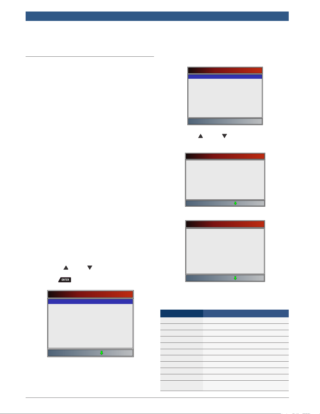
en
|
28
|
User guide
| HDS 200/HDS 250
HD Scan Tool for Class 4-8 Diesel, Light and Medium Vehicles
581618 | REV. B | 11.2018
Bosch Automotive Service Solutions Inc.
• Review Data
• Print Data
• System Setup
6.1 I/M Monitors (Emissions)
The I/M Monitors (Inspection / Maintenance) function is
used to view a snapshot of the operations for the emis-
sion system on OBD II vehicles. I/M Monitors is a very
useful function. To guarantee no faults exist make sure
all monitors are ok or n/a and no DTCs exist. Refer to the
vehicles service manual for the drive cycle operation.
During normal driving conditions, the vehicle computer
scans the emission system. After a specific amount of
drive time (each monitor has specific driving conditions
and time required), the computer monitors decide if the
vehicles emission system is working correctly or not as
well as detecting out of range values. When the monitor
status is:
• ok - vehicle was driven enough to complete the
monitor.
• inc (Incomplete) - vehicle was not driven enough to
complete the monitor.
• n/a (not applicable)- vehicle does not support that
monitor.
Depending on vehicle, disconnecting or a discharged
battery may erase DTCs and clear monitor status. Moni-
tors may be reset by:
• Erasing codes
• Vehicle control modules losing power
The I/M Monitors function can be run key on engine
running (KOER) or key on engine off (KOEO).
Extreme weather and/or road conditions can prevent a
monitor from running. Also, some monitors may require
a cold start to complete.
From the HD OBD menu or Global Automotive OBDII
menu.
1. Select I/M Monitors.
• Use the UP and DOWN keys until I/M
Monitors is highlighted.
• Press .
Global Automotive OBDII
I/M Monitors
Read Codes
Erase Codes
MIL Status
State OBD Check
View Data
Record Data
View Freeze Data
Drive Cycle Monitor
Two types of I/M Monitors test are:
• Since DTCs Cleared - shows status of the monitors
since the DTCs were last erased.
• This Drive Cycle - shows status of monitors since
the start of the current drive cycle. Refer to the
vehicle service manual for more detailed information
on emission-related monitors and their status.
Some vehicles do not support This Drive Cycle. If vehi-
cle supports both types of monitors the I/M Monitors
Menu displays.
I/M Monitors
Since DTCs Cleared
This Drive Cycle
2. View summary of monitor status.
• Use the UP and DOWN keys (if required).
Depending on monitor test, one of these two screens will
be present.
Since DTCs Cleared
Misfire Monitor
Fuel System Mon
Comp Component
Catalyst Mon
Htd Catalyst
Evap System Mon
Sec Air System
A/C Refrig Mon
Oxygen Sens Mon
ok
ok
ok
ok
n/a
inc
n/a
n/a
ok
OR
This Drive Cycle
Misfire Monitor
Fuel System Mon
Comp Component
Catalyst Mon
ok
ok
ok
inc
Htd Catalyst
Evap System Mon
Sec Air System
n/a
dis
n/a
A/C Refrig Mon n/a
Oxygen Sens Mon inc
Abbreviations and names for OBD II monitors supported
by the scan tool are shown below. They are required by
the United States Environmental Protection Agency
(EPA). Not all monitors are supported by all vehicles.
Monitors Expanded Name
Misfire Monitor Misfire monitor
Fuel System Mon Fuel System Monitor
Comp Component Comprehensive components monitor
Catalyst Mon Catalyst monitor
Htd Catalyst Heated catalyst monitor
Evap System Mon Evaporative system monitor
Sec Air System Secondary air system monitor
A/C Refrig Mon Air conditioning refrigerant monitor
Oxygen Sens Mon Oxygen sensor monitor
Oxygen Sens Htr Oxygen sensor heater monitor
EGR/VVT Sys Mon
Exhaust gas recirculation or variable
valve timing monitor
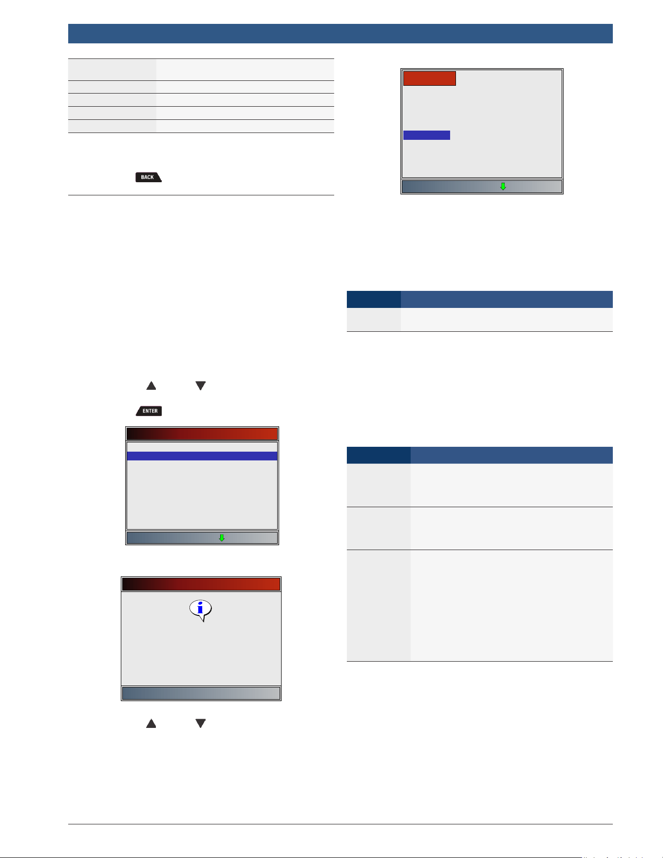
581618 | REV. B | 11.2018
Bosch Automotive Service Solutions Inc.
HDS 200/HDS 250
HD Scan Tool for Class 4-8 Diesel, Light and Medium Vehicles
|
User guide | 29
|
en
NMHC Cat Mon
Non-methane hydrocarbon catalyst mon-
itor
NOX Treat Mon Nitrogen oxide treatment monitor
Boost Pres Mon Boost pressure monitor
Exhst Gas Sensr Exhaust gas sensor
PM Filter Mon Particulate matter filter monitor
3. Return to the HD OBD menu or Global Automotive
OBDII menu.
• Press .
6.2 Read Codes
The Read Codes function allows the scan tool to read
the DTCs from the vehicle’s control modules. DTCs are
used to help determine the cause of a problem or prob-
lems with a vehicle. These codes cause the control
module to illuminate the malfunction indicator lamp
(MIL) when emission-related or driveability fault occurs.
When referring to the engine control module, MIL is also
known as service engine soon or check engine lamp.
Read Codes can be done with the key on engine off
(KOEO) or with the key on engine running (KOER).
From the the HD OBD menu or Global Automotive
OBDII menu:
1. Select Read Codes.
• Use the UP and DOWN keys until Read
Codes is highlighted.
• Press .
Global Automotive OBDII
Read Codes
I/M Monitors
Erase Codes
MIL Status
State OBD Check
View Data
Record Data
View Freeze Data
Drive Cycle Monitor
If no DTCs are present, a message stating “No codes found”
is displayed.
Read Codes
Press ENTER to continue
No codes found
2. View and write down the DTCs.
• Use the UP and DOWN keys until the
desired choice is highlighted.
This screen indicates where the Read Codes information
is located.
DTC Description
DTC Type
X/Y
Module
DTC#
DTC Number - number of the trouble code found in
vehicle service information.
X of Y - Indication that code x of y is being viewed,
where x is the code being viewed of the total y.
Module - The address of the module (e.g. Mod $28) is
shown in this field. The table below describes modules
supported.
Module Description
MOD $XX
Module address for the OBD II/EOBD mod-
ule reporting the DTC
DTC Description - This area is reserved for the text
describing the trouble code listed in the DTC number
field.
DTC Type - This area is reserved for providing additional
information about the DTC. Multiple DTC types may be
possible for a given DTC number. Not all vehicles sup-
port DTC types.
This table describes possible DTC types.
DTC Type Description
Confirmed
Confirmed codes are reported when a
component, sensor, or other part of the
vehicle is indication a malfunction is pres-
ent.
Current
Codes transmitted through the PCMs da-
ta stream when a trouble condition is ac-
tive and cannot be erased. The problem
must be repaired to remove the DTC.
Pending
Pending codes are also referred to as
continuous monitor or maturing codes.
An intermittent fault causes the control
module to store a code in memory. If the
fault does not occur within a certain num-
ber of warm-up cycles (depending on ve-
hicle), the code clears from memory. If
fault occurs a specific number of times,
the code matures into a DTC and the MIL
illuminates or blinks. This function can be
used with KOEO or KOER.
Examples of Read Codes information screens follow.
In this example, module (MOD) $18 is reporting the
DTCs.
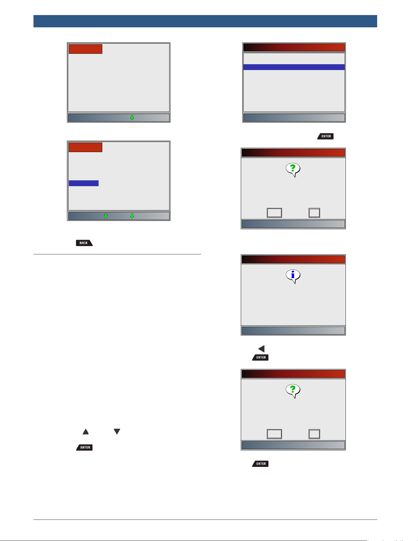
en
|
30
|
User guide
| HDS 200/HDS 250
HD Scan Tool for Class 4-8 Diesel, Light and Medium Vehicles
581618 | REV. B | 11.2018
Bosch Automotive Service Solutions Inc.
Intake Air Temperature Sensor
1 Circuit High Input
1/3
Mod $18
P0113
Pending indicates a global OBD II/EOBD pending code.
Vehicle Speed Sensor Out
of Range Self Test
PENDING
2/3
Mod $18
P1501
3. Return to HD OBD menu or Global Automotive
OBDII menu.
• Press .
6.3 Erase Codes
The Erase Codes function deletes DTCs and resets I/M
Monitor data from vehicle’s control module(s). Perform
this function key on engine off (KOEO). Do not start the
engine.
The Erase Codes function may also erase View Freeze
Data, O2 Monitor Tests, and Diagnostic Monitor Test
results depending on vehicle.
The Erase Codes function sets monitors to inc.
Perform Erase Codes function only after systems have been
checked completely and DTCs have been written down.
After servicing the vehicle, erase stored DTCs and verify
no codes have returned. If a DTC returns, problem has
not been fixed or other faults are present.
Permanent DTCs cannot be erased with the Erase Codes
function.
Depending on which monitor sets a code, the vehicle
may need to be driven and the monitor ran before con-
cluding that the fault is repaired.
From HD OBD menu or Global Automotive OBDII menu:
1. Select Erase Codes.
• Use the UP and DOWN keys until Erase
Codes is highlighted.
• Press .
Global Automotive OBDII
Read Codes
Erase Codes
MIL Status
State OBD Check
View Data
Record Data
View Freeze Data
Drive Cycle Monitor
I/M Monitors
• If diagnostic results and codes are not to be
erased select NO and press .
Erase Codes
Are you sure you want to
erase diagnostic results and
codes?
No
Yes
• Selecting NO displays a “Command canceled”
message.
Erase Codes
Press ENTER to continue
Command canceled
2. Select YES to erase diagnostic results and codes.
• Use the LEFT arrow key.
• Press .
Erase Codes
Are you sure you want to
erase diagnostic results and
codes?
No
Yes
3. Observe “Command sent” message is displayed.
• Press .
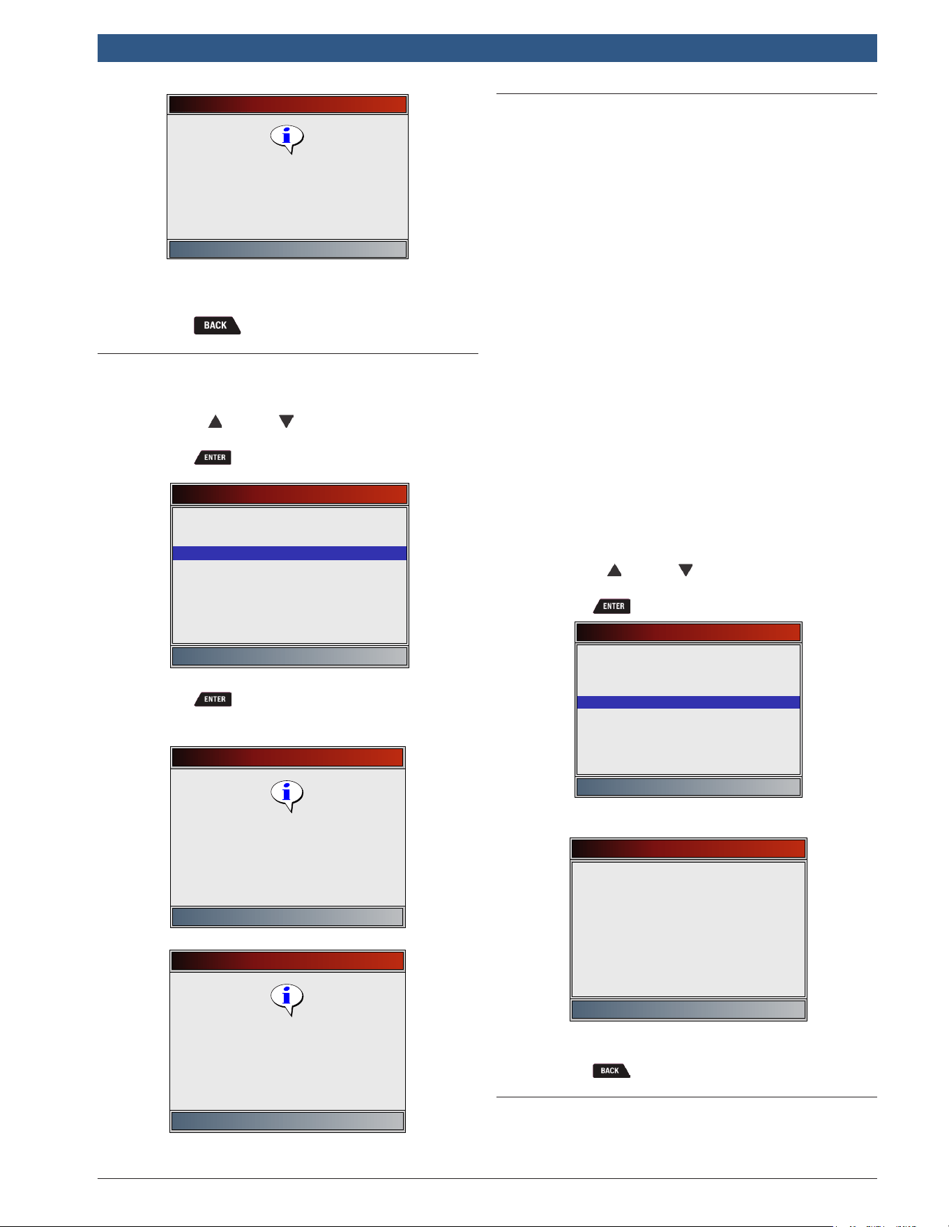
581618 | REV. B | 11.2018
Bosch Automotive Service Solutions Inc.
HDS 200/HDS 250
HD Scan Tool for Class 4-8 Diesel, Light and Medium Vehicles
|
User guide | 31
|
en
Erase Codes
Press ENTER to continue
Command sent
Codes remaining:0
4. Return to HD OBD menu or Global Automotive
OBDII menu.
• Press .
6.4 MIL Status
From HD OBD menu or Global Automotive OBDII menu:
1. Select MIL Status.
• Use the UP and DOWN keys until MIL
Status is highlighted.
• Press .
Global Automotive OBDII
Read Codes
MIL Status
Erase Codes
State OBD Check
View Data
Record Data
View Freeze Data
Drive Cycle Monitor
I/M Monitors
2. View MIL Status.
• Press to return to HD OBD menu or
Global Automotive OBDII menu.
MIL is ON
Press ENTER to continue
MIL lamp should be ON if
engine is running
MIL is OFF
Press ENTER to continue
MIL lamp should be OFF
engine is running
6.5 State OBD Check
The State OBD Check function is used to display a basic
status of the vehicles OBD system.
• Malfunction indicator lamp (MIL) status
• Codes found
• I/M monitors
Erase Codes deletes DTCs and resets I/M monitors from
vehicle’s computer module(s).
The State OBD Check function has the following areas:
• MIL Status ON or OFF
• Number of Codes Found
• Number of Monitors OK
• Number of Monitors Inc
• Number of Monitors N/A
State OBD Check should be done with the key on
engine running (KOER) due to showing MIL status.
The number of codes found are only Global OBD II codes and
not pending codes.
The number of monitors that are either ok, inc, or na are
only Since DTCs Cleared and not This Drive Cycle.
Refer to”6.1 I/M Monitors (Emissions)” on page
28 and “6.2 Read Codes” on page 29 for more
detailed information about the results.
From HD OBD menu or Global Automotive OBDII menu:
1. Select State OBD Check.
• Use the UP and DOWN keys until State
OBD Check is highlighted.
• Press .
Global Automotive OBDII
Read Codes
State OBD Check
Erase Codes
View Data
MIL Status
Record Data
View Freeze Data
Drive Cycle Monitor
I/M Monitors
2. View State OBD Check display.
State OBD Check
MIL Status
Codes Found
Monitors OK
Monitors Inc
Monitors N/A
OFF
0
3
4
4
3. Return to HD OBD menu or Global Automotive
OBDII menu.
• Press .
6.6 View Data
The View Data function allows real time viewing of the
vehicle’s computer module’s parameter identification
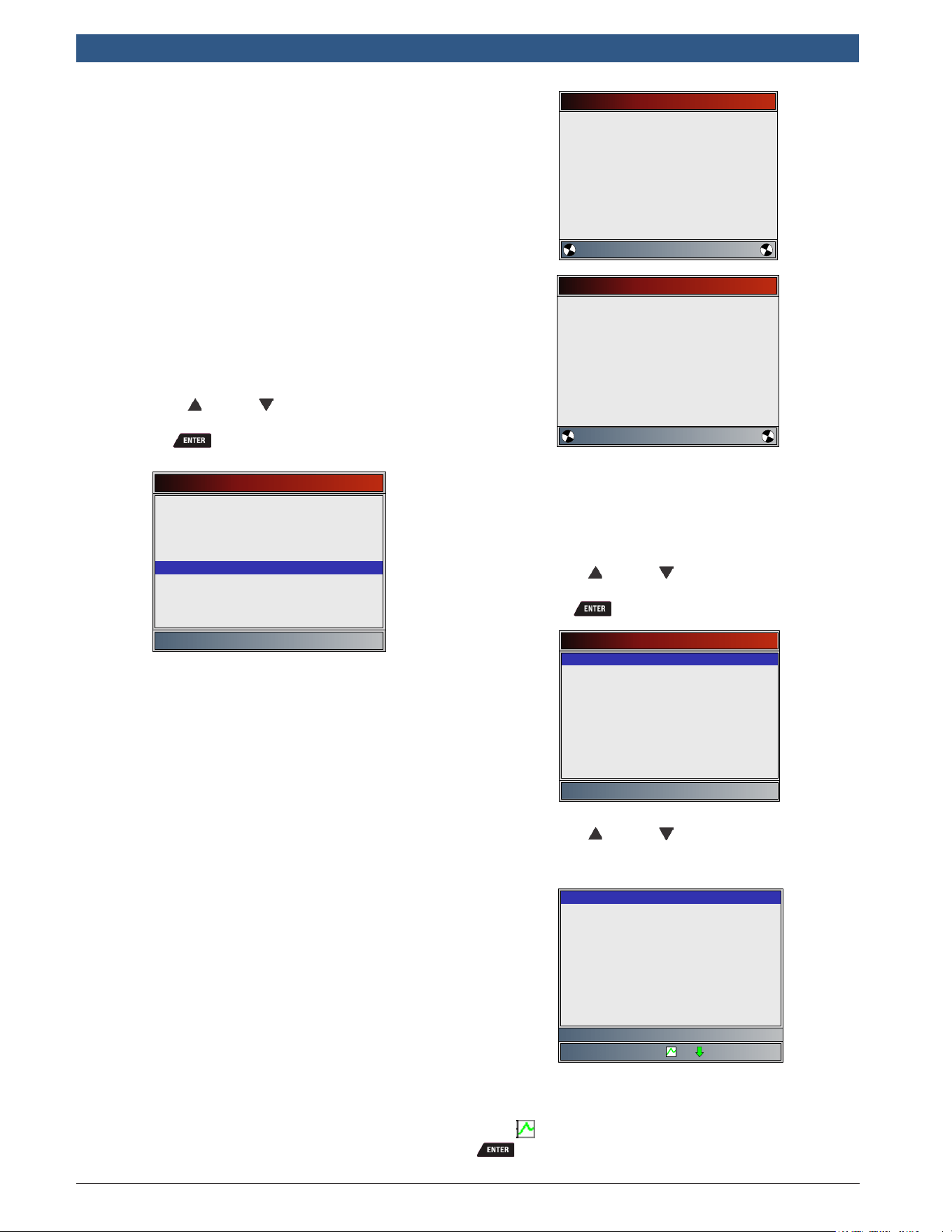
en
|
32
|
User guide
| HDS 200/HDS 250
HD Scan Tool for Class 4-8 Diesel, Light and Medium Vehicles
581618 | REV. B | 11.2018
Bosch Automotive Service Solutions Inc.
(PID) data. As the computer monitors the vehicle, infor-
mation is simultaneously transmitted to scan tool.
View Data allows the following items to be viewed on
the scan tool:
• Sensor data
• Operation of switches
• Operation of solenoids
• Operation of relays
View Data can be shown as:
• Entire Data List
• Custom Data List
Apart from Read Codes, View Data is the most useful
diagnostic function for isolating the cause of a vehicle
operation problem.
From HD OBD menu or Global Automotive OBDII menu:
1. Select View Data.
• Use the UP and DOWN keys until View
Data is highlighted.
• Press .
Global Automotive OBDII
Read Codes
View Data
Erase Codes
State OBD Check
MIL Status
Record Data
View Freeze Data
Drive Cycle Monitor
I/M Monitors
2. Observe while the scan tool validates PID MAP.
• PID MAP validation is the tool asking the vehicle
which PIDs are supported. Refer to “8
Appendix A—Global OBD II PID Definitions” on
page 42 for a complete list of PIDs supported
by the tool.
• Multiple PIDs may be sent if vehicle is equipped
with more than one computer module (for
example a powertrain control module [PCM]
and a transmission control module [TCM]). The
scan tool identifies them by their identification
names (ID) assigned by manufacturer (i.e. $10
or $1A).
• If one or more control module stops responding,
the scan tool displays a message.
– If continuing, dashes will replace data in
right-hand column.
– If NO is selected, then the scan tool
attempts to re-establish communication
with that module.
Validating PIDs
Please Wait
Waiting for vehicle to
respond
Validating PIDs
Please Wait
Validating PID List
PID 19/329
View Entire List
View Entire List shows all supported PID data for the
vehicle being tested.
From Select Data to View menu:
1. Select Entire Data List.
• Use the UP and DOWN keys until Entire
Data List is highlighted.
• Press .
Select Data to View
Entire Data List
Custom Data List
English/Metric
2. View PIDs on scan tool.
• Use the UP and DOWN keys.
• Refer to “8 Appendix A—Global OBD II PID
Definitions” on page 42.
ABS LOAD(%)
ABSLT TPS($01)
ABSLT TPS($07)
ACC POS D(%)
BARO PRS(”HG)
CALC LOAD(%)
CALC LOAD(%)
CAT TEMP11(°F)
CLR DIST(mi)
CLR DIST(mi)
0.0
6.3
6.3
0.0
29.2
0.0
0.0
73
499
513
Absolute Load Value
If Long PID/SPN Names is turned ON, the expanded text
for the PID will scroll on the bottom line of display. Refer
to “Long PID/SPN Names” on page 13.
If the icon displays while a PID is selected, press
to select PIDs to graph. A maximum of 2 PIDs can
be graphed.
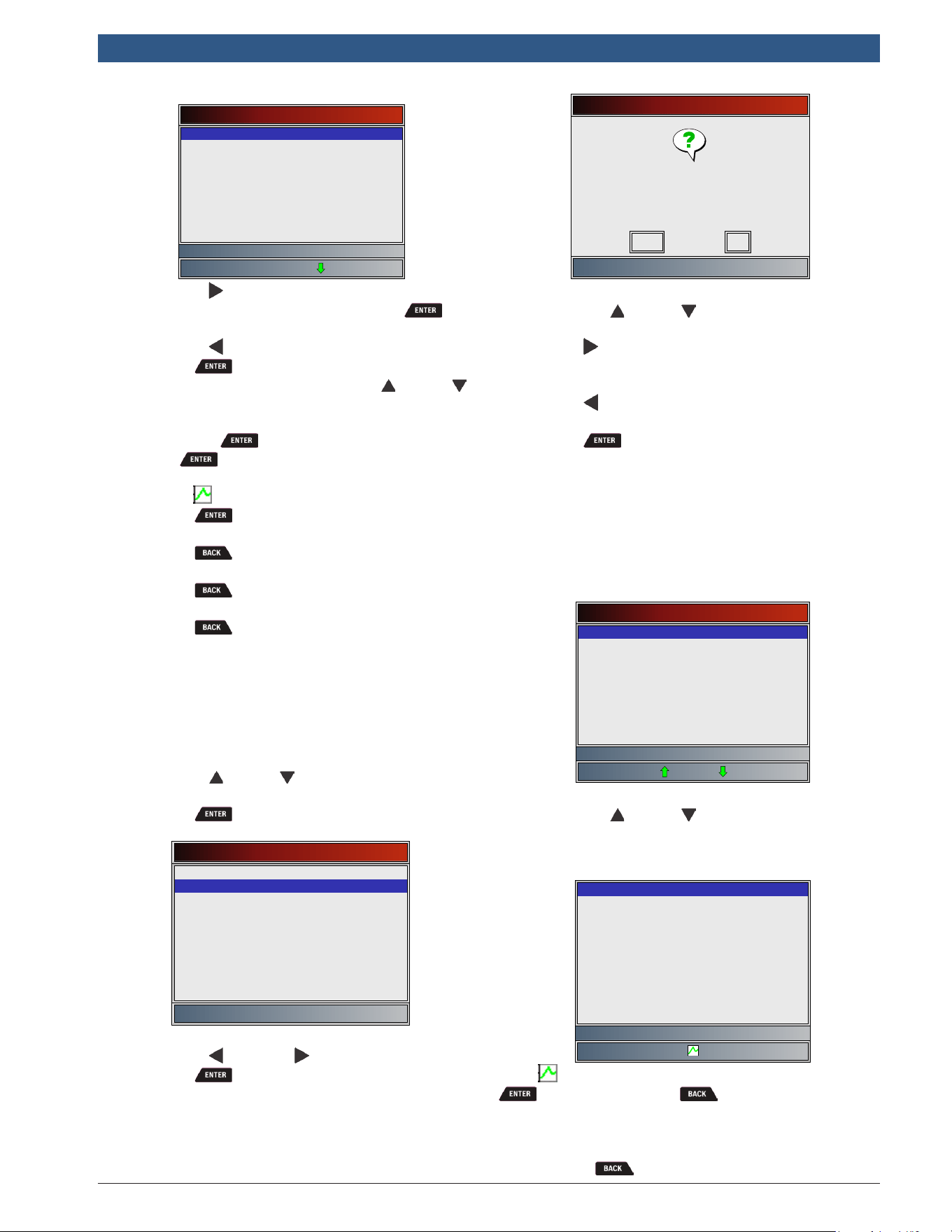
581618 | REV. B | 11.2018
Bosch Automotive Service Solutions Inc.
HDS 200/HDS 250
HD Scan Tool for Class 4-8 Diesel, Light and Medium Vehicles
|
User guide | 33
|
en
Select PIDs to Graph
✓ABSLT TPS(%)
CALC LOAD(%)
COOLANT(°F)
ENG SPEED(RPM)
EQ RATIO11
IAT(°F)
IGN ADV(°)
LT FTRM1(%)
Throttle Position
• Use the RIGHT arrow key to select/deselect
PIDs. The highlighted PID from when was
pressed is already selected
• Use the LEFT arrow key to deselect all PIDs.
• Press to view graph of selected PIDs.
• When graphing two PIDs, use the UP and
DOWN keys to highlight the desired PID, which
will also display the appropriate scale.
• Press the key to pause the graph. Press
the key again to continue graphing.
• If the icon displays while a PID is selected
press to view graph.
3. Return to PID screen.
• Press .
4. Return to Select Data to View menu.
• Press .
5. Return to Datastream Menu.
• Press .
Custom List Select
The Custom Data List allows certain PIDs from the View
Entire Data List, such as those PIDs that apply to a
specific driveability symptom or system, to be selected.
From Select Data to View menu:
1. Select Custom List Select.
• Use the UP and DOWN keys until Custom
Data List is highlighted.
• Press .
Select Data to View
Entire Data List
Custom Data List
English/Metric
2. Select View Instructions or Not.
• Use the LEFT and RIGHT keys.
• Press .
Custom Setup
Do you want to view
instructions for creating a
custom data list?
No
Yes
3. Select PIDs to View.
• Use the UP and DOWN keys to move up
and down list.
• The RIGHT arrow selects or deselects data
parameter. All selected data values are marked
with a √ symbol.
• The LEFT arrow deselects all marked data
parameters.
• The key starts recording data or displaying
selected data parameters.
• If Long PID/SPN Names is turn ON, the
expanded text for the PID will scroll on the
bottom line of display. Refer to “Long PID/SPN
Names” on page 13.
• Selected PIDs are kept until you exit View Data
and return to the Datastream Menu.
Select Custom List
MIL STATUS
O2S11(V)
O2S12(V)
O2S21(V)
O2S22(V)
OBD2 STAT
PTO STATUS
ST FTRM11(%)
Malfunction Indicator Lamp Statu
4. View PIDs on scan tool.
• Use the UP and DOWN arrow key.
• Refer to “8 Appendix A—Global OBD II PID
Definitions” on page 42.
ABS TPS B(%)
MIL STATUS
0.0
Off
Throttle Position B
If the icon displays while a PID is selected, press
to view graph. Press to return to PID Screen.
Refer to”View Entire List” on page 32 for instructions
on how to select PIDs to graph and how to view graph.
5. Return to Select Data to View Menu.
• Press .
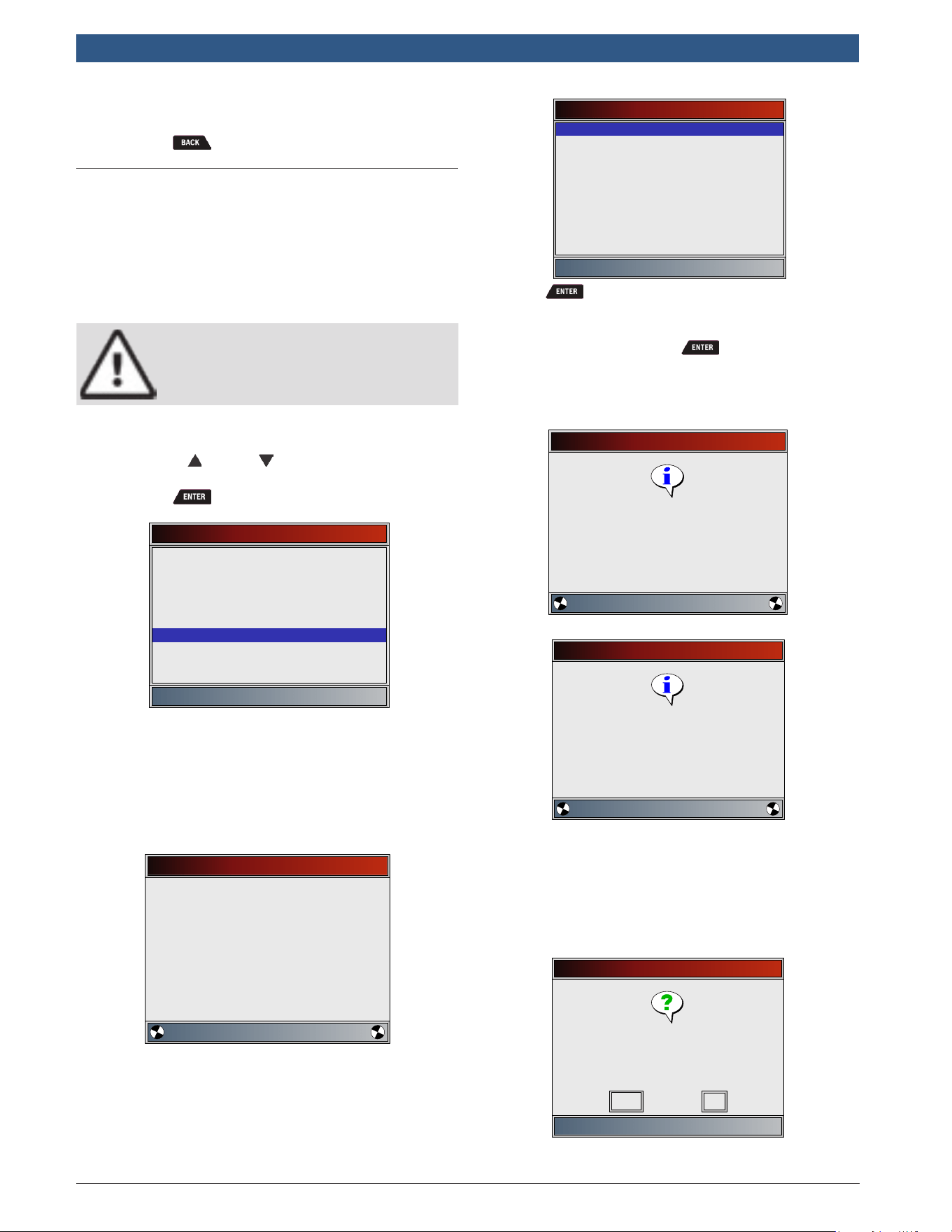
en
|
34
|
User guide
| HDS 200/HDS 250
HD Scan Tool for Class 4-8 Diesel, Light and Medium Vehicles
581618 | REV. B | 11.2018
Bosch Automotive Service Solutions Inc.
6. Return to HD OBD menu or Global Automotive
OBDII menu.
• Press .
6.7 Record Data
The Record Data function records PIDs while vehicle is
parked or being driven. The Record Data function is
mainly used for diagnosing intermittent driveability
problems that cannot be isolated by any other method.
The recording time varies. A recording consists of frames
of data before the trigger and several frames after the
trigger.
CAUTION
Two people must be in vehicle when driv-
ing. One to drive and the other to operate
the scan tool.
From HD OBD menu or Global Automotive OBDII menu:
1. Select Record Data.
• Use the UP and DOWN keys until Record
Data is highlighted.
• Press .
Global Automotive OBDII
Read Codes
Record Data
Erase Codes
View Data
MIL Status
State OBD Check
View Freeze Data
Drive Cycle Monitor
I/M Monitors
2. Follow all instructions on display.
• The scan tool can maintain 5 recordings per
vehicle. If there are already 5 recordings stored,
the scan tool will ask which recording to over-
write.
• Scan tool validates list of global PIDs from
vehicle.
Validating PIDs
Please Wait
Validating PID List
PID 116/329
3. Refer to”6.6 View Data” on page 31 to setup
Custom List or View Entire List and Pre-Trigger
Setup to set the number of frames to keep prior to
triggering the recording.
Select Data to Record
Entire Data List
Custom Data List
Pre-Trigger Setup
4. Press to begin recording.
• Data continues to be saved until either:
– Record memory is full.
– Operator presses .
• Scan tool recording times vary. A recording
consists of frames of data before trigger and
several frames after trigger.
Recording
Press ENTER to trigger
recording
Collecting pretrigger data
Recording
Press ENTER to end recording
Collecting data for frame #4
5. After recording, scan tool displays a prompt to
Playback Data.
• Select NO to return to Datastream Menu.
• Select YES to display recorded data.
• Refer to”Recording” on page 17 for instruc-
tions on how to play back data.
Record Data
Playback data?
No
Yes
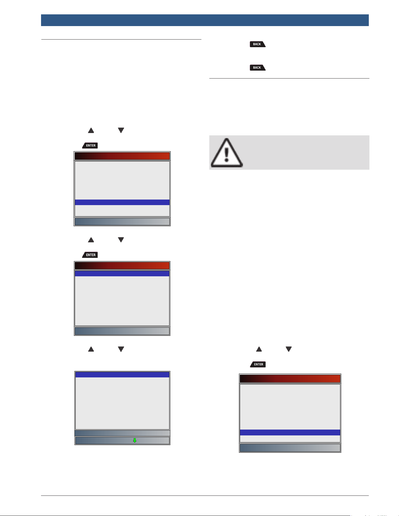
581618 | REV. B | 11.2018
Bosch Automotive Service Solutions Inc.
HDS 200/HDS 250
HD Scan Tool for Class 4-8 Diesel, Light and Medium Vehicles
|
User guide | 35
|
en
6.8 View Freeze Data
When an emission-related fault occurs, certain vehicle
conditions are recorded by the on-board computer. This
information is referred to as freeze frame data. View
Freeze Data is a snapshot of the operating conditions at
the time of an emission-related fault. View Freeze Data
can be overwritten by faults with a higher priority. If
codes were erased, View Freeze Data may not be stored
in vehicle memory depending on vehicle.
From HD OBD menu or Global Automotive OBDII menu:
1. Select View Freeze Data.
• Use the UP and DOWN keys until View
Freeze Data is highlighted.
• Press .
Global Automotive OBDII
Read Codes
View Freeze Data
Erase Codes
View Data
MIL Status
State OBD Check
Record Data
Drive Cycle Monitor
I/M Monitors
2. Select frame if more than one frame is present.
• Use the UP and DOWN keys until the
desired frame is highlighted.
• Press .
Select Data to View
P0102 (MOD $10)
Long PID/SPN Names
English/Metric
3. View PIDs on scan tool.
• Use the UP and DOWN keys.
• Refer to “8 Appendix A—Global OBD II PID
Definitions” on page 42.
TROUB CODE
FUEL SYS 1
FUEL SYS 2
CALC LOAD(%)
COOLANT (°F)
ST FTRM1(%)
LT FTRM1(%)
MAP(”HG)
ENG SPEED(RPM)
VEH SPEED(MPH)
P2122
N/A
N/A
0.0
-40
0.0
0.0
28.1
0
0
Definition that caused Freeze Fra
• If Long PID/SPN Names is turned on, the
expanded text for the PID will scroll on the bot-
tom line of the display. Refer to “Long PID/SPN
Names” on page 13.
4. Select another frame to view (if available).
• Press .
5. Return to HD OBD menu or Global Automotive
OBDII menu.
• Press .
6.9 Drive Cycle Monitor
The Drive Cycle Monitor function is very similar to I/M
Monitors though the Drive Cycle Monitor is used to
view real-time operations of the emissions system on
OBD II vehicles. Drive Cycle Monitor continuously
updates as the vehicle reports operations of the emis-
sion system.
CAUTION
Two people must be in vehicle when driv-
ing. One to drive and the other to operate
the scan tool.
• Refer to the vehicle service manual for the drive
cycle operation.
Drive Cycle Monitor can be used if you want to drive the
vehicle until all of the monitors are OK.
During normal driving conditions, the vehicle computer
scans the emission system. After a specific amount of
drive time (each monitor has specific driving conditions
and time requirements), the computer monitors will
decide if the vehicle emissions system is working cor-
rectly or not as well as detecting out a range of values.
When the monitor status is:
• “ok” - vehicle has been driven enough for function.
• “inc” (incomplete) - vehicle was not driven enough
to complete all of the monitors.
• “n/a” (not applicable) - vehicle does not support
that monitor.
Reset monitors by:
• Erasing codes.
• Vehicle computer module losing power (on some
vehicles).
From HD OBD menu or Global Automotive OBDII menu:
1. Select Drive Cycle Monitor.
• Use the UP and DOWN keys until Drive
Cycle Monitor is highlighted.
• Press .
Global Automotive OBDII
Read Codes
Drive Cycle Monitor
Erase Codes
View Data
MIL Status
State OBD Check
Record Data
View Freeze Data
I/M Monitors
• Two types of drive cycle monitors are:
– Since DTCs Cleared shows status of the
monitors since the Diagnostic Trouble
Codes were last erased.
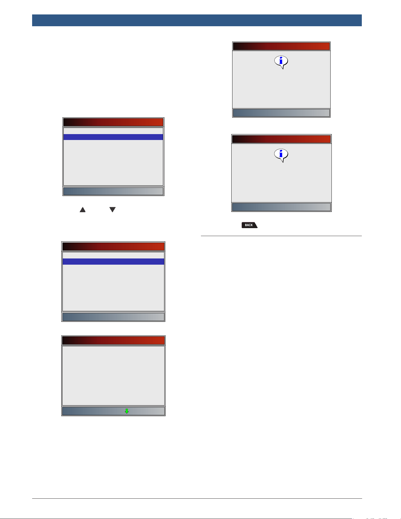
en
|
36
|
User guide
| HDS 200/HDS 250
HD Scan Tool for Class 4-8 Diesel, Light and Medium Vehicles
581618 | REV. B | 11.2018
Bosch Automotive Service Solutions Inc.
– This Drive Cycle shows status of monitors
since start of current drive cycle. Refer to
the vehicle service manual for more detailed
information on emission-related monitors
and their status.
– Some vehicles do not support This Drive
Cycle. If vehicle supports both types of
drive cycle monitors the Drive Cycle Moni-
tor menu will display.
Drive Cycle Monitor
Since DTCs Cleared
This Drive Cycle
2. View summary of monitor status.
• Use the UP and DOWN keys (if required).
3. Depending on the drive cycle monitors, either the
This Drive Cycle or the Since DTCs Cleared screen
will display.
This Drive Cycle
Catalyst Mon
Oxygen Sens Mon
Oxygen Sens Htr
EGR/VVT Sys Mon
inc
inc
inc
inc
OR
Since DTCs Cleared
Misfire Monitor
Fuel System Mon
Comp Component
Catalyst Mon
Htd Catalyst
Evap System Mon
Sec Air System
A/C Refrig Mon
Oxygen Sens Mon
ok
ok
ok
ok
n/a
inc
n/a
n/a
ok
• The scan tool display is continuously updated.
Monitors that are “ok” will disappear and only
the “inc” monitors will remain displayed. Moni-
tors designated “n/a” are not displayed.
• When all Monitors are “OK”, a screen stating “All
supported monitors are OK” will display.
This Drive Cycle
Press ENTER to continue
All supported monitors are OK
OR
Since DTCs Cleared
Press ENTER to continue
All supported monitors are OK
4. Return to Special Tests Menu.
• Press .
6.10 O2 Monitor Tests
OBD II regulations require applicable vehicles monitor
and test oxygen (O2) sensors to determine problems
related to fuel and emissions. The O2 Monitor Tests
allows retrieval of completed O2 sensors monitor test
results.
• The O2 Monitor Tests is not an on-demand test. O2
sensors are not tested when selected via the menu.
O2 sensors are tested when engine operating condi-
tions are within specified limits.
• If the vehicle communicates using a controller area
network (CAN), O2 Monitor Tests are not supported
by vehicle. A message is displayed. Refer to “6.11
Diagnostic Monitor Tests” on page 37 for O2
monitor data.
• O2 sensors are located before (upstream) and after
(downstream) catalyst(s). Sensors are named (xy)
for their position to both cylinder banks and cata-
lysts.
– The O2 sensor for cylinder bank 1 has prefix 1y
while O2 sensor for cylinder bank 2 has prefix
2y.
– The O2 sensor upstream of catalyst (closest to
engine) has suffix x1 while O2 sensor down-
stream of catalyst has suffix x2. If vehicle con-
tains more catalysts, O2 sensor downstream of
second catalyst has suffix x3 and O2 sensor
downstream of next catalyst has suffix x4.
– For example, O2S21 is upstream O2 sensor for
cylinder bank 2.
The following O2 Sensor Tests are available:
• Rich-to-lean sensor threshold voltage
• Lean-to-rich sensor threshold voltage
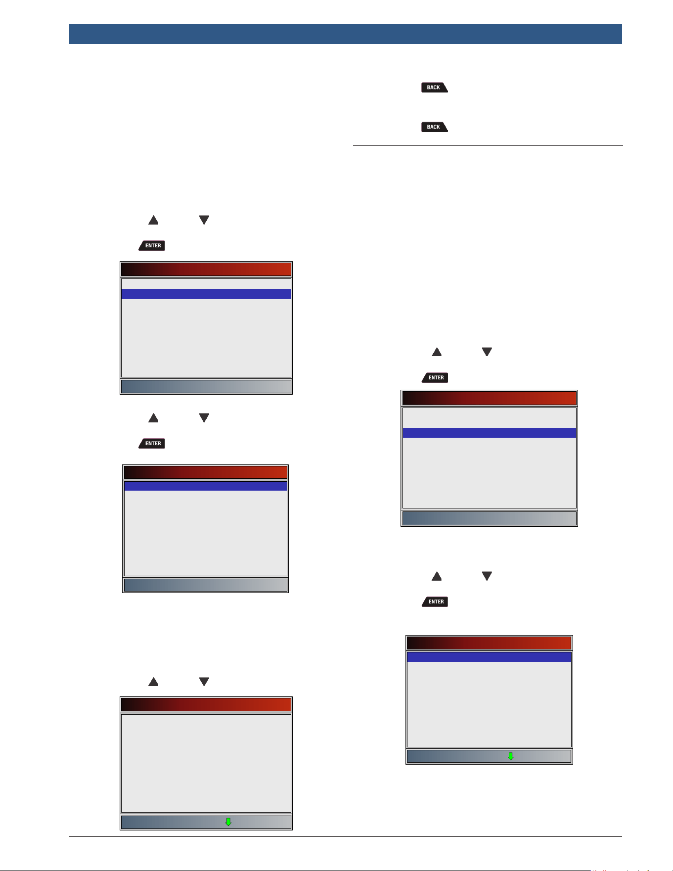
581618 | REV. B | 11.2018
Bosch Automotive Service Solutions Inc.
HDS 200/HDS 250
HD Scan Tool for Class 4-8 Diesel, Light and Medium Vehicles
|
User guide | 37
|
en
• Low sensor voltage for switch time
• High sensor voltage for switch time
• Rich-to-lean sensor switch time
• Lean-to-rich sensor switch time
• Minimum sensor voltage test cycle
• Maximum sensor voltage test cycle
• Time between sensor transitions
• Sensor period
• Manufacturer specific tests
From HD OBD menu or Global Automotive OBDII menu:
1. Select O2 Monitor Tests.
• Use the UP and DOWN keys until O2
Monitor Tests is highlighted.
• Press .
Global Automotive OBDII
Diagnostic Monitor Tests
O2 Monitor Tests
On-Board Systems
Review Data
Vehicle Information
Modules Present
Print Data
System Setup
Drive Cycle Monitor
2. Select O2 sensor.
• Use the UP and DOWN keys until the
desired O2 monitor is highlighted.
• Press .
Select O2 Sensor
O2 Bank1 Sensor1
• The O2 sensors located upstream (before cata-
lyst) may perform differently than ones located
downstream (after catalyst).
• Test IDs are shown for unknown O2 sensor
tests.
3. View results of selection.
• Use the UP and DOWN keys.
O2 Bank1 Sensor1
Test $86
MOD
MAX
MEAS
MIN
$09
128
128
128
Test $8D
MOD
MAX
MEAS
MIN
$09
255
128
128
4. Return to O2 Sensor Tests menu.
• Press .
5. Return to HD OBD menu or Global Automotive
OBDII menu.
• Press .
6.11 Diagnostic Monitor Tests
The Diagnostic Monitor Test function is useful after
servicing or after erasing a vehicle’s memory. Test
results do not necessarily indicate a faulty component or
system.
• Non-CAN vehicles Diagnostic Monitor Test receives test
results for emission-related powertrain components
and systems that are not continuously monitored.
• CAN vehicles Diagnostic Monitor Test receives test
results for emission-related powertrain components and
systems that are and are not continuously monitored.
• Vehicle manufacturer is responsible for assigning
test and component IDs.
From HD OBD menu or Global Automotive OBDII menu:
1. Select Diagnostic Monitor Tests.
• Use the UP and DOWN keys until Diagnos-
tic Monitor Tests is highlighted.
• Press .
Global Automotive OBDII
O2 Monitor Tests
Diagnostic Monitor Tests
On-Board Systems
Review Data
Vehicle Information
Modules Present
Print Data
System Setup
Drive Cycle Monitor
• Applicable diagnostic monitor tests are dis-
played.
2. Review test results displayed on scan tool.
• Use the UP and DOWN keys until desired
result is highlighted.
• Press .
Non-CAN Vehicles
Select Diag Mon Test
Test $03
Test $49
Test $4A
Test $62
Test $76
Test $78
Test $81
Test $9A
Test $9B
Refer to appropriate vehicle service manual for test IDs
and definitions.
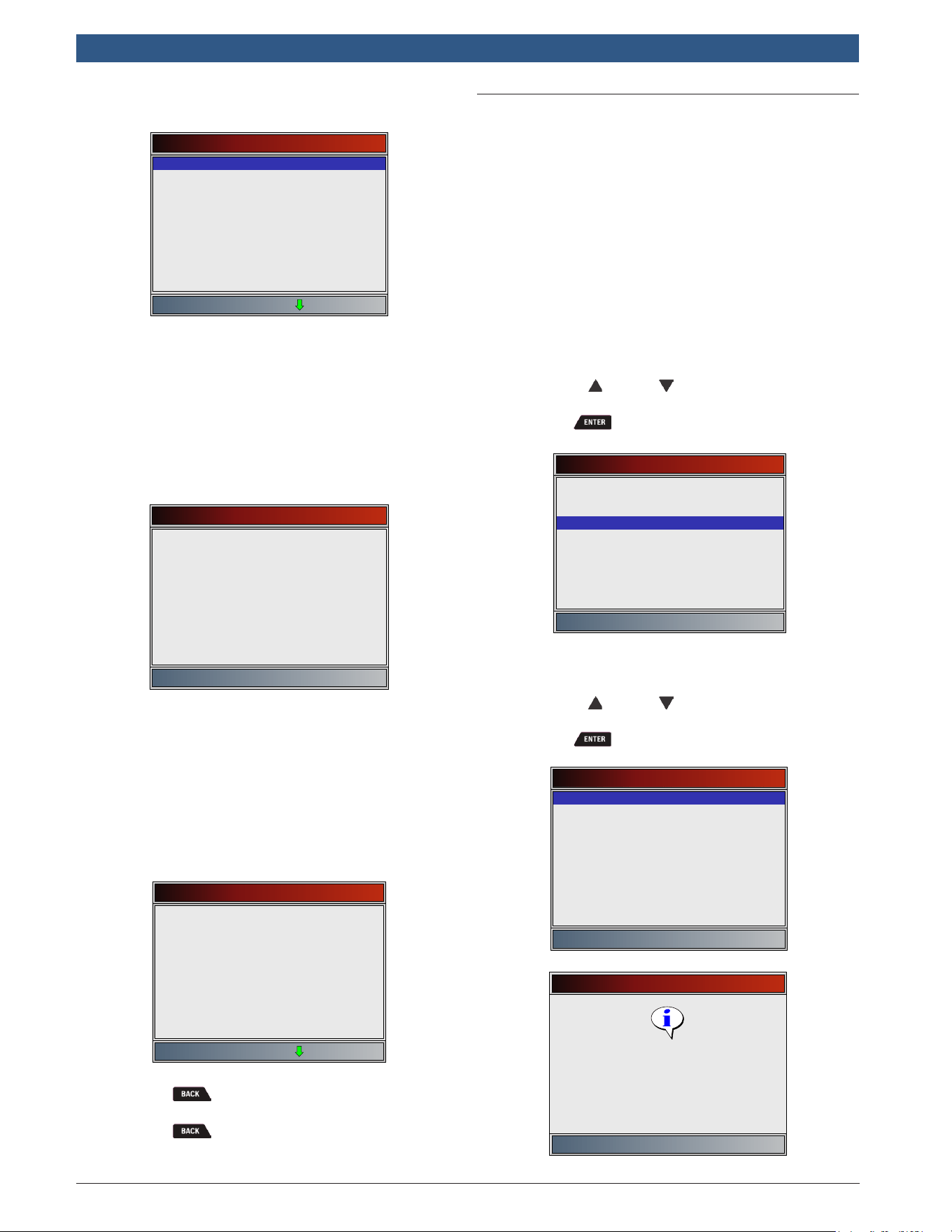
en
|
38
|
User guide
| HDS 200/HDS 250
HD Scan Tool for Class 4-8 Diesel, Light and Medium Vehicles
581618 | REV. B | 11.2018
Bosch Automotive Service Solutions Inc.
CAN Vehicles
Select Diag Mon Test
O2 Sensor B1S1
O2 Sensor B1S2
O2 Sensor B2S1
O2 Sensor B2S2
Catalyst B1
Catalyst B2
EGR Mon B1
EVAP (0.090”)
EVAP (0.020”)
On Non-CAN vehicles the scan tool displays:
– Test data (test ID)
– Maximum value (MAX)
– Test measurements (MEAS)
– Minimum value (MIN)
– Status (STS)
– Measurements and Specification values are
hexadecimal numbers (i.e., $1A, $FE, $11.)
– Module (MOD)
Test $03
ID
MOD
MAX
MEAS
MIN
STS
01
$09
----
00
00
OK
• On CAN vehicles scan tool displays:
– Test performed. The test performed can be
$## if test is not defined. Refer to vehicle
service manual for details.
– Measured values and units of measured
(such as volts, amps, and seconds).
– Status of monitor test data.
– Module ID where the monitor test data
came from.
O2 Sensor B1S1
RICH-LN Thresh
MOD
MAX
MEAS
MIN
STS
$07
0.4497(V)
0.4497(V)
0.4497(V)
OK
3. Return to Select Test menu.
• Press .
4. Return to Special Tests Menu.
• Press .
6.12 On-Board Systems
The On-Board Systems test allows the scan tool to
control operation of vehicle components, tests or sys-
tems.
• Some manufacturers do not allow tools to control
vehicle systems. A vehicle not supporting an on-
board system is identified by a message that is
displayed when selected.
• Refer to the vehicle service manual for on-board
systems instructions.
• The manufacturer is responsible for determining the
criteria to automatically stop test. Refer to appropri-
ate vehicle service manual.
From HD OBD menu or Global Automotive OBDII menu:
1. Select On-Board Systems.
• Use the UP and DOWN keys until On-
Board Systems is highlighted.
• Press .
Global Automotive OBDII
O2 Monitor Tests
On-Board Systems
Diagnostic Monitor Tests
Review Data
Vehicle Information
Modules Present
Print Data
System Setup
Drive Cycle Monitor
• A list of on-board systems and components
available for testing are shown on the display.
2. Select test.
• Use the UP and DOWN keys until desired
test is highlighted.
• Press .
On-Board Systems
EVAP System Test
On-Board Systems
Press ENTER to continue
Command sent
3. Return to On-Board Systems menu.
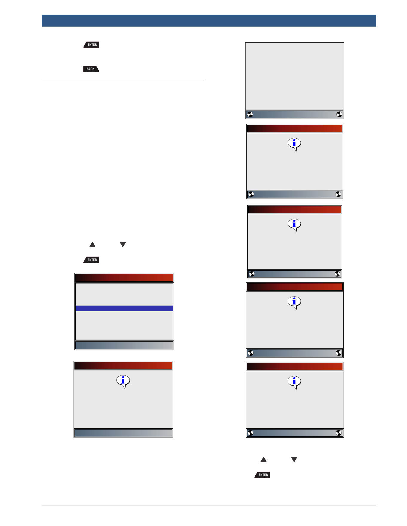
581618 | REV. B | 11.2018
Bosch Automotive Service Solutions Inc.
HDS 200/HDS 250
HD Scan Tool for Class 4-8 Diesel, Light and Medium Vehicles
|
User guide | 39
|
en
• Press .
4. Return to HD OBD menu or Global Automotive
OBDII menu.
• Press .
6.13 Vehicle Information
The Vehicle Information function allows the scan tool to
request the vehicle’s VIN number, calibration ID(s) which
identifies software version in vehicle control module(s),
calibration verification numbers (CVN(s)) and in-use
performance tracking.
• Vehicle Information function applies to model year
2000 and newer OBD II compliant vehicles.
• The scan tool cannot verify if data is correct for
scanned vehicles.
• CVNs are calculated values required by OBD II regu-
lations.
• The CVN calculation may take several minutes.
• CVNs are reported to determine if emission-related
calibrations have been changed. Multiple CVNs may
be reported for a control module.
• In-use performance tracking tracks performance of
key I/M Monitors.
From HD OBD menu or Global Automotive OBDII menu:
1. Select Vehicle Information.
• Use the UP and DOWN keys until Vehicle
Information is highlighted.
• Press .
Global Automotive OBDII
O2 Monitor Tests
Vehicle Information
Diagnostic Monitor Tests
Review Data
On-Board Systems
Modules Present
Print Data
System Setup
Drive Cycle Monitor
Vehicle Information
Press ENTER to continue
Verify key ON
Engine OFF.
Please Wait
Communicating with the
vehicle
WORKING
Vehicle Information
Press BACK to exit
Retrieving VIN data. It may
take up to 1.5 minutes.
Vehicle Information
Press BACK to exit
Retrieving CVN data. It may
take up to 1.5 minutes.
Vehicle Information
Press BACK to exit
Retrieving CALID data. It may
take up to 1.5 minutes.
Vehicle Information
Press BACK to exit
Retrieving IPT data. It may
take up to 1.5 minutes.
2. Select information to view from the menu.
• Use the UP and DOWN keys until desired
selection is highlighted.
• Press .
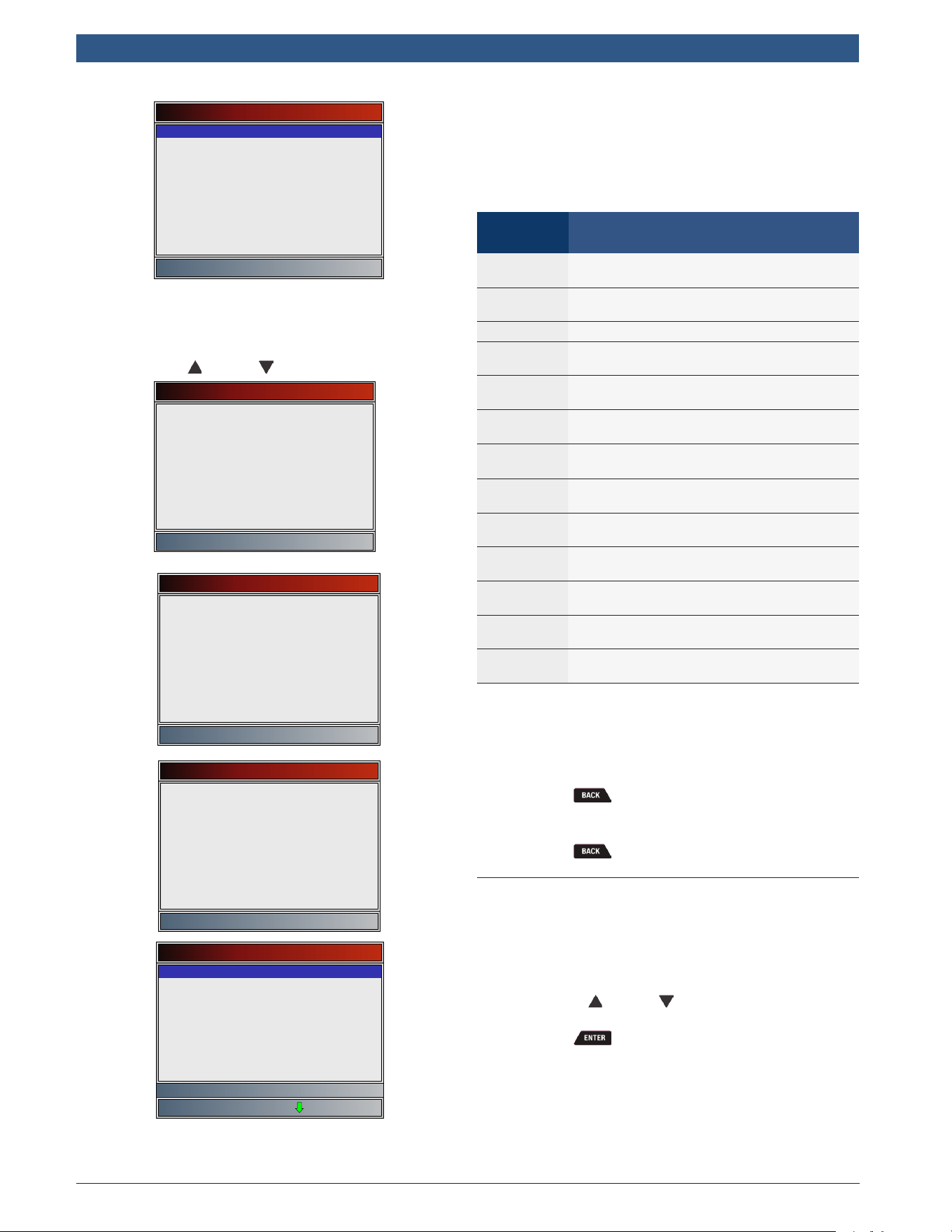
en
|
40
|
User guide
| HDS 200/HDS 250
HD Scan Tool for Class 4-8 Diesel, Light and Medium Vehicles
581618 | REV. B | 11.2018
Bosch Automotive Service Solutions Inc.
Vehicle Information
VIN
CVN
CAL ID
IPT
• If the selected menu item has data for more
than one module, a menu listing all modules
returning data for that menu item is shown.
3. View information supported by vehicle.
• Use the UP and DOWN keys (if required).
VIN (MOD $09)
1HGCM56866A018504
CVN (MOD $09)
00 5C 02 52
CAL ID (MOD $ 09)
37805-RAD-A590
--------------
IPT (MOD $ 09)
OBDCOND
IGNCNTR
CATCOMP1
CATCOND1
CATCOMP2
CATCOND2
O2SCOMP1
O2SCOND1
0
0
0
0
0
0
0
0
Monitor Conditions Encountered
• In the above examples, Module $09 returned
data. Scroll down to view information. CVNs are
shown as hexadecimal numbers.
• Abbreviations and names for in-use performance
tracking data supported by the Tool are shown
below. Not all data is supported by all vehicles.
Abbrevi-
ated Name
Expanded Name
In-Use Perf
Tracking
In-Use Performance Tracking
OBDCOND
OBD Monitoring Conditions Encountered
Counts
IGNCNTR Ignition Counter
CATCOMPX
Catalyst Monitor Completion Counts
Bank x
CATCONDX
Catalyst Monitor Conditions Encountered
Counts Bank x
O2SCOMPX
O2 Sensor Monitor Completion Counts
Bank x
O2SCONDX
O2 Sensor Conditions Encountered
Counts Bank x
EGRCOMP
EGR Monitor Completion Condition
Counts
EGRCOND
EGR Monitor Conditions Encountered
Counts
AIRCOMP
AIR Monitor Completion Condition
Counts (Secondary Air)
AIRCOND
AIR Monitor Conditions Encountered
Counts (Secondary Air)
EVAPCOMP
EVAP Monitor Completion Condition
Counts
EVAPCOND
EVAP Monitor Conditions Encountered
Counts
• If message INVALID displays on screen, the data
returned from the vehicle is incorrect, or is not
formatted in accordance with OBD II specifica-
tions.
4. Return to Vehicle Information menu.
• Press .
5. Return to HD OBD menu or Global Automotive
OBDII menu.
• Press .
6.14 Modules Present
The scan tool identifies the module IDs and communica-
tion type for all Global OBD II modules in the vehicle.
From the HD OBD menu or Global Automotive OBDII
menu:
1. Select Modules Present.
• Use the UP and DOWN keys until Modules
Present is highlighted.
• Press .
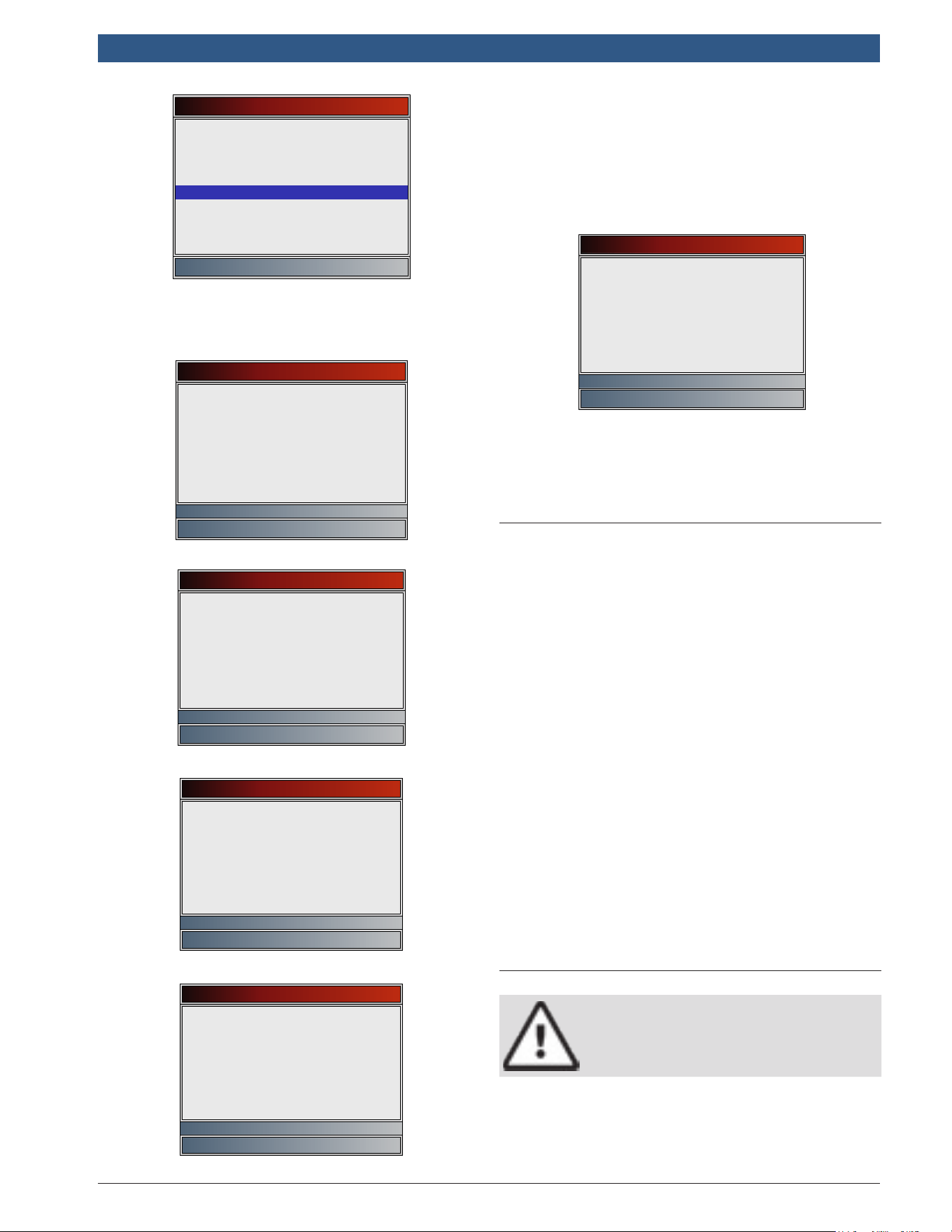
581618 | REV. B | 11.2018
Bosch Automotive Service Solutions Inc.
HDS 200/HDS 250
HD Scan Tool for Class 4-8 Diesel, Light and Medium Vehicles
|
User guide | 41
|
en
Global Automotive OBDII
O2 Monitor Tests
Modules Present
Diagnostic Monitor Tests
Review Data
On-Board Systems
Vehicle Information
Print Data
System Setup
Drive Cycle Monitor
The types of protocols (communication types) sup-
ported by the scan tool are:
• ISO 9141-2 protocol is shown as ISO.
Modules Present
ID Protocol
$40 ISO*
Press ENTER to continue
• SAE J1850 protocol is shown as VPWM or PWM.
Modules Present
ID Protocol
$10 VPWM*
Press ENTER to continue
OR
Modules Present
ID Protocol
$10 PWM*
Press ENTER to continue
• ISO 15765-4 protocol is shown as CAN.
Modules Present
ID Protocol
$01 CAN*7e9
$00 CAN*7e8
Press ENTER to continue
Since CAN vehicles use module IDs larger than 2 digits,
the scan tool assigns a 2 digit module ID to be used in
place of the actual CAN module ID. The module ID
assigned for the CAN module ID is used in all functions
of the scan tool.
• ISO 14230-4 protocol is shown as K2K (Keyword
2000).
Modules Present
ID Protocol
$10 K2K*
Press ENTER to continue
In the above examples, the * indicates the protocol used
to communicate to the vehicle’s control module.
7 Troubleshooting
7.1 Error Messages
Check the following if an error message displays:
• Verify ignition key is in the ON and not in the ACCES-
SORIES position.
• Make sure the DLC Cable is attached to vehicle’s
data link connector (DLC) and scan tool.
• Look at DLC and check for cracked or recessed pins,
or for any substance that could prevent a good
electrical connection.
• Test for continuity between the DLC wiring and the
computer. In an extreme case, there may be a bro-
ken wire.
• Check for bent or broken pins.
• With the engine off, check for blown fuses in the
vehicle fuse box.
• Make sure the vehicle’s control module has a good
ground. If the computer case is grounded, then
clean the connection and apply a conductive (dielec-
tric) grease to the mating surfaces.
• With the key on engine off (KOEO), verify vehicle
battery voltage is at least 8.0V.
• Verify the control module is not defective. Refer to
the service manual to diagnose the control module.
7.2 Scan Tool Does Not Power Up
WARNING
Review Safety Messages on page 4
before troubleshooting.
If scan tool will not power up, communicate with vehicle
control module, pass scan tool self-tests, or functions
incorrectly in any other way, do the following:
• Check and replace the batteries if needed.
• Clean the DLC pins.
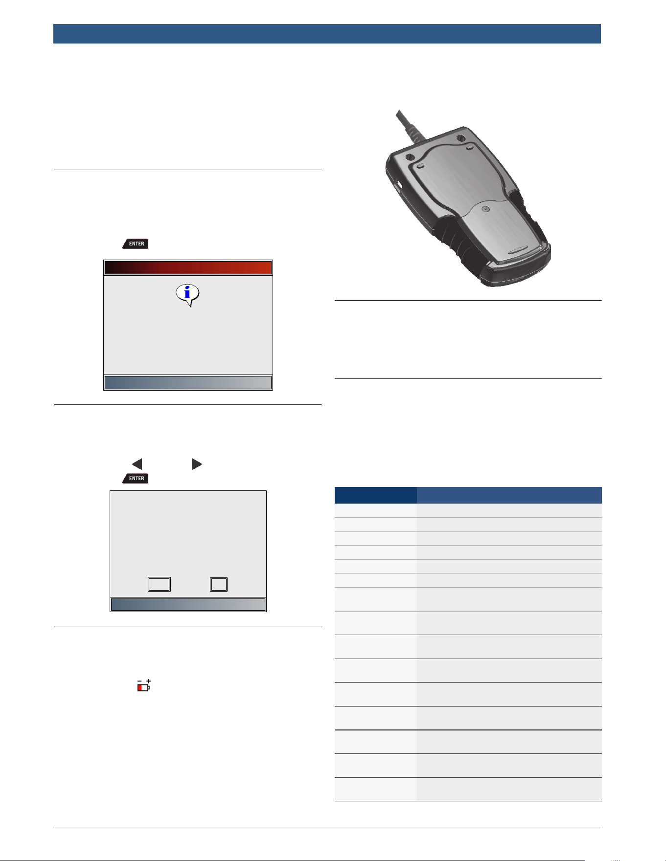
en
|
42
|
User guide
| HDS 200/HDS 250
HD Scan Tool for Class 4-8 Diesel, Light and Medium Vehicles
581618 | REV. B | 11.2018
Bosch Automotive Service Solutions Inc.
• Disconnect and reconnect DLC making sure it is
connected correctly.
• Check vehicle battery to make sure at least 8.0 volts
is present.
• Contact customer service.
• With the engine off, check for blown fuses in the
vehicle fuse box.
7.3 Vehicle Communication Fault
The vehicle’s control module(s) enters into an unrecov-
erable state.
1. Turn vehicle key to off position.
• Wait 10 seconds.
• Press .
Vehicle Required
Press ENTER to continue
Please verify the tool is
connected to the vehicle with
the ignition key turned on.
7.4 Operating Error or Erroneous Data
An Operating Error or Erroneous Data occurs if vehicle’s
computer(s) stop(s) communicating with the scan tool.
1. Make selection.
• Use the LEFT and RIGHT keys.
• Press .
Check connection! Try
again?
LINK ERROR
No
Yes
7.5 Battery Replacement
The scan tool requires 4-AAA alkaline batteries to oper-
ate without vehicle power.
• When the batteries need to be replaced, the low-
battery icon ( ) is displayed.
• Rechargeable batteries do not last as long as alka-
line types and are not recommended.
• Non-rechargeable Lithium (Li) battery can be used.
Lithium types last longer than the alkaline types, but
they are more expensive.
1. Place display face-down on a non-abrasive surface.
2. Remove battery cover by turning phillips screw
counterclockwise. Slide battery cover off.
3. Remove batteries and properly discard.
4. Install four new AAA Alkaline batteries.
5. Reinstall battery cover by sliding battery cover on.
Install phillips screw turning it clockwise. Do not
overtighten screw.
7.6 Tool Self-Tests
Tool Self-Tests check the display, keys, and internal
memory.
• Refer to “4 Using the Scan Tool” on page 10 for
the operation procedures for scan tool self-tests.
7.7 Technical Support
Toll-Free Number: 1-855-267-2483.
8 Appendix A—Global OBD II
PID Definitions
Although there are in excess of 300 PIDs, the tool only
displays the PIDs the vehicle supports.
PID PID Description
ABS FRP Absolute Fuel Rail Pressure
ABS LOAD Absolute Load Value
ABS TPS B, C Throttle Position B, C
ABSLT TPS Absolute Throttle Position
ACC POS D Accelerator Pedal D, E, F
ACC POS REL Relative Accelerator Pedal Position
AECD1_TIME1,
TIME 2
Total Run Time with EI-AECD #1 Timer
1 Active, #2 Timer Active
AECD10_TIME1,
TIME 2
Total Run Time with EI-AECD #10
Timer 1 Active, #2 Timer Active
AECD11_TIME1,
TIME 2
Total Run Time with EI-AECD #11
Timer 1 active, #2 Timer Active
AECD12_TIME1,
TIME 2
Total Run Time with EI-AECD #12
Timer 1 active, #2 Timer Active
AECD13_TIME1,
TIME 2
Total Run Time with EI-AECD #13
Timer 1 active, #2 Timer Active
AECD14_TIME1,
TIME 2
Total Run Time with EI-AECD #14
Timer 1 active, #2 Timer Active
AECD15_TIME1,
TIME 2
Total Run Time with EI-AECD #15
Timer 1 active, #2 Timer Active
AECD16_TIME1,
TIME 2
Total Run Time with EI-AECD #16
Timer 1 active, #2 Timer Active
AECD17_TIME1,
TIME 2
Total Run Time with EI-AECD #17
Timer 1 active, #2 Timer Active

581618 | REV. B | 11.2018
Bosch Automotive Service Solutions Inc.
HDS 200/HDS 250
HD Scan Tool for Class 4-8 Diesel, Light and Medium Vehicles
|
User guide | 43
|
en
PID PID Description
AECD18_TIME1,
TIME 2
Total Run Time with EI-AECD #18
Timer 1 active, #2 Timer Active
AECD19_TIME1,
TIME 2
Total Run Time with EI-AECD #19
Timer 1 active, #2 Timer Active
AECD2_TIME1,
TIME 2
Total Run Time with EI-AECD #2 Timer
1 Active, #2 Timer Active
AECD20_TIME1,
TIME 2
Total Run Time with EI-AECD #20
Timer 1 active, #2 Timer Active
AECD3_TIME1,
TIME 2
Total Run Time with EI-AECD #3 Timer
1 Active, #2 Timer Active
AECD4_TIME1,
TIME 2
Total Run Time with EI-AECD #4 Timer
1 Active, #2 Timer Active
AECD5_TIME1,
TIME 2
Total Run Time with EI-AECD #5 Timer
1 Active, #2 Timer Active
AECD6_TIME1,
TIME 2
Total Run Time with EI-AECD #6 Timer
1 Active, #2 Timer Active
AECD7_TIME1,
TIME 2
Total Run Time with EI-AECD #7 Timer
1 Active, #2 Timer Active
AECD8_TIME1,
TIME 2
Total Run Time with EI-AECD #8 Timer
1 Active, #2 Timer Active
AECD9_TIME1,
TIME 2
Total Run Time with EI-AECD #9 Timer
1 Active, #2 Timer Active
ALCOHOL Alcohol Fuel Percent
BARO PRS Barometric Pressure
BAT_PWR Hybrid Battery Pack Remaining Life
BP_A_ACT, B_
ACT
Boost Pressure Sensor A, Sensor B
BP_A_CMD, B_
CMD
Commanded Boost Pressure A, Pres-
sure B
BP_A_STAT, B_
STAT
Boost Pressure A Control Status, B
Control Status
CACT 11, 12
Charge Air Cooler Temperature Bank
1 Sensor 1 supported, Sensor 2
supported
CACT 21,22
Charge Air Cooler Temperature Bank
2 Sensor 1 supported, Sensor 2
supported
CALC LOAD Calculated Engine Load
CAT TEMP11,
TEMP12
Cataltic Converter Temp Bank1, Temp
Bank 3
CAT TEMP21,
TEMP22
Cataltic Converter Temp Bank2, Temp
Bank 4
CLR DIST Distance since erase
CLR TIME Minutes Run since Erase
CLR TRPS Warmups Since Erase
CMD EQ RAT Commanded Equivalence Ratio
COOLANT Engine Coolant Temp
DPF_REG_AVGD Average Distance Between DPF Regen
DPF_REG_AVGT Average Time Between DPF Regen
DPF_REG_STAT
Diesel Particulate Filter (DPF) Regen
Status
DPF_REG_TYP
Diesel Particulate Filter (DPF) Regen
Type
DPF_REGEN_
PCT
Normalized Trigger for DPF Regen
DPF1_DP,
DPF2_DP
Diesel Particulate Filter (DPF) Bank 1
Delta Pressure Bank 2 Delta Pressure
DPF1_INP,
DPF2_INP
Diesel Particulate Filter (DPF) Bank 1
Inlet Pressure, Bank 2 Inlet Pressure
DPF1_INT,
DPF2_INT
DPF Bank 1 Inlet Temperature Sensor,
Bank 2 Inlet Temperature Sensor
PID PID Description
DPF1_OUTP,
DPF2_OUTP
Diesel Particulate Filter (DPF) Bank
1 Outlet Pressure, Bank 2 Outlet
Pressure
DPF1_OUTT,
DPF2_OUTT
DPF Bank 1 Outlet Temperature Sen-
sor, Bank 2 Outlet Temperature Sensor
ECT 1, 2
Engine Coolant Temperature 1, Tem-
perature 2
EGR CMD Comanded EGR
EGR ERR Exhaust Gas Recirculation Error
EGR_A_ACT, B_
ACT
Actual EGR A Duty Cycle / Position, B
Duty Cycle / Position
EGR_A_CMD, B_
CMD
Commanded EGR A Duty Cycle / Posi-
tion, B Duty Cycle / Position
EGR_A_ERR, B_
ERR
EGR A Error, B Error
EGRT 11, 21
Exhaust Gas Recirculation Tempera-
ture Bank 1 Sensor 1, Bank 2 Sensor 1
EGRT 12, 22
Exhaust Gas Recirculation Tempera-
ture Bank 1 Sensor 2, Bank 2 Sensor 2
EGT 11, 21
Exhaust Gas Temperature (EGT) Bank
1 Sensor 1, Bank 2 Sensor 1
EGT 12, 22
Exhaust Gas Temperature (EGT) Bank
1 Sensor 2, Bank 2 Sensor 2
EGT 13, 23
Exhaust Gas Temperature (EGT) Bank
1 Sensor 3, Bank 2 Sensor 3
EGT 14, 24
Exhaust Gas Temperature (EGT) Bank
1 Sensor 4, Bank 2 Sensor 4
EMIS_SUP
Emission requirements to which vehi-
cle is designed
ENG RUN Time Since Engine Start
ENG SPEED Engine RPM
EOT Engine Oil Temperature
EP_1, 2
Exhaust Pressure Sensor Bank 1, Bank
2
EQ RATIO Equivalence Ratio
EVAP PURGE Commanded EVAP Purge
EVAP VP EVAP Vapor Pressure
EVAP VPA Absolute EVAP Vapor Pressure
FRP_A, B Fuel Rail Pressure A, B
FRP_A_CMD, B_
CMD
Commanded Fuel Rail Pressure A, B
FRT_A, B Fuel Rail Temperature A, B
FUEL LEVEL Fuel Level Input
FUEL PRES Fuel Rail Pressure
FUEL SYS 1, 2
Fuel System 1 Loop Status, System 2
Loop Status
FUEL TYPE Fuel Type
FUEL_RATE Engine Fuel Rate
FUEL_TIMING Fueling Injection Timing
GPL_STAT Glow Plug Lamp Status
IAF_A_CMD, B_
CMD
Commanded Intake Air Flow A Control,
B Control
IAF_A_REL, B_
REL
Relative Intake Air Flow A Position, B
Position
IAT Intake Air Temp
IAT 11, 21
Intake Air Temperature Sensor Bank 1
Sensor 1, Bank 2 Sensor 1
IAT 12, 22
Intake Air Temperature Sensor Bank 1
Sensor 2, Bank 2 Sensor 2

en
|
44
|
User guide
| HDS 200/HDS 250
HD Scan Tool for Class 4-8 Diesel, Light and Medium Vehicles
581618 | REV. B | 11.2018
Bosch Automotive Service Solutions Inc.
PID PID Description
IAT 13, 23
Intake Air Temperature Sensor Bank 1
Sensor 3, Bank 2 Sensor 3
ICP_A, B Injection Control Pressure A, B
ICP_A_CMD, B_
CMD
Commanded Injection Control Pres-
sure A, B
IDLE_TIME Total Idle Run Time
IGN ADV Timing Advance
LAMBDA11, 21
02 Sensor Lambda Bank 1 Sensor 1,
Bank 2 Sensor 1
LAMBDA12, 22
02 Sensor Lambda Bank 1 Sensor 2,
Bank 2 Sensor 2
LT FTRM1 Long Term Fuel Trim 1 or 3
LT FTRM2 Long Term Fuel Trim 2 or 4
LT SEC FT1, 2,
3, 4
Long Term Secondary O2 Sensor Fuel
Trim 1, 2, 3, 4
MAF, A, B Mass Air Flow, A, B
MAP, A, B Manifold Absolute Pressure, A, B
MIL DIST MIL_DIST
MIL STATUS Malfunction Indicator Lamp
MIL TIME Minutes Run by MIL activated
MST Manifold Surface Temperature
N/D_STAT Auto Trans Neutral Drive Status
N/G_STAT Manual Trans Neutral Gear Status
NNTE_Stat NOx NTE control area status
NOX 11, 21
NOx Sensor Concentration Bank 1
Sensor 1, Bank 2 Sensor 1
NOX 12,22
NOx Sensor Concentration Bank 1
Sensor 2, Bank 2 Sensor 2
NOX LEVEL HI,
HI1, HI2, HI3,
HI4
SCR inducement system actual state
10K history HI1 (0-10000 km), 10K his-
tory HI2 (10000-20000 km), 10K his-
tory HI3 20000-30000 km), 10K history
HI4 (30000-40000 km): NOx emission
too high
NOX_ADS_DE-
SUL
NOx Adsorber Desulfurization Status
NOX_ADS_RE-
GEN
NOx Adsorber Regen Status
NWI_TIME
Total Run Time by the Engien whicle
NOx warning mode is activated
O2S
O2 Voltage or Current indicates
Bank / Sensor
O2S11_PCT,
O2S21_PCT
02 Sensor Concentration Bank 1 Sen-
sor 1, Bank 2 Sensor 1
O2S12_PCT,
O2S22_PCT
02 Sensor Concentration Bank 1 Sen-
sor 2, Bank 2 Sensor 2
OBD2 STAT OBD Status
OUT TEMP Ambient Air Temp
PM 11, PM 21
PM Sensor Mass Concentration Bank
1 Sensor 1, Bank 2 Sensor 1
PNTE_Stat PM NTE control area status
PTO STATUS PTO Status
PTO_STAT Power Take Off (PTO) Status
PTO_TIME Total Run Time With PTO Active
REAG_DEMD
Average Demanded Reagent
Consumption
REAG_LVL Reagent Tank Level
REAG_RATE Average Reagent Consumption
REL FRP Relative Fuel Rail Pressure
PID PID Description
REL TPS Relative Throttle Position
RUN_TIME Total Engine Run Time
SCR REAG DEV,
DEV1, DEV2,
DEV3, DEV4
SCR inducement system actual state
10K history DEV1 (0 - 10000 km), 10K
history DEV2 (10000 - 20000 km),
10K history DEV3 (20000 - 30000 km),
10K history DEV4 (30000 - 40000 km):
deviation of reagent consumption
SCR REAG
LOW, LOW1,
LOW2, LOW3,
LOW4
SCR inducement system actual state
10K history LOW1 (0 - 10000 km), 10K
history LOW2 (10000 - 20000 km),
10K history LOW3 (20000 -
30000 km), 10K history LOW4
(30000 - 40000 km): reagent level too
low
SCR RE-
AG WRONG,
WRONG1,
WRONG2,
WRONG3,
WRONG4
SCR inducement system actual state
10K history WRONG1 (0 - 10000 km),
10K history WRONG2 (10000 -
20000 km), 10K history WRONG3
(20000 - 30000 km), 10K history
WRONG4 (30000 - 40000 km): incor-
rect reagent
SCR SYS AC-
TIVE
SCR inducement system actual state:
inducement system active
SCR_DIST_1D
Distance travelled in current 10K block
(0 - 10000 km)
SCR_DIST_1N,
2N, 3N, 4N
Distance travelled while induce-
ment system active in current 10K
block 1N (0 - 10000 km), 20K block
2N (10 - 20000 km), 30K block 3N
(20 - 30000 km), 40K block 4N
(30 - 40000 km)
SECOND AIR Secondary Air Status
ST FTRM Fuel Trim Bank / Sensor
ST FTRM1, 3 Short Term Fuel Trim1 or 3
ST FTRM2, 4 Short Term Fuel Trim2 or 4
ST SEC
FT1, 2, 3, 4
Short Term Secondary O2 Sensor Fuel
Trim 1, 2, 3, 4
TAC_A_CMD, B_
CMD
Commanded Throttle Actuator A Con-
trol, B Control
TAC_A_REL, B_
REL
Relative Throttle A Position, B Position
TCA_CINP, TCB_
CINP
Turbocharger Compressor Inlet Pres-
sure Sensor A, Pressure Sensor B
TCA_CINT, TCB_
CINT
Turbocharger A Compressor Inlet Tem-
perature, Turbocharger B
TCA_COUTT,
TCB_COUTT
Turbocharger A Compressor Outlet
Temperature, Turbocharger B
TCA_RPM, TCB_
RPM
Turbocharger A RPM, B RPM
TCA_TOUTT,
TCB_TOUTT
Turbocharger A Turbine Outlet Temper-
ature, Turbocharger B
TCA_TINT, TCB_
TINT
Turbocharger A Turbine Inlet Tempera-
ture, Turbocharger B
THROT CMD Commanded Throttle Actuator Control
TP G Absolute Throttle Position G
TQ_ACT Actual Engine - Percent Torque
TQ_DD
Driver's Demand Engine - Percent
Torque
TQ_MAX1,
MAX2, MAX3,
MAX4, MAX5
Engine percent torque at
idle point 1, 2, 3, 4, 5
TQ_REF Engine Reference Torque
TROUB CODE Code causing the Freeze Frame

581618 | REV. B | 11.2018
Bosch Automotive Service Solutions Inc.
HDS 200/HDS 250
HD Scan Tool for Class 4-8 Diesel, Light and Medium Vehicles
|
User guide | 45
|
en
PID PID Description
VEH SPEED Vehicle Speed
VGT_A_ACT Variable geometry turbo A position
VGT_A_ACT, B_
ACT
Variable Geometry Turbo A Position,
Turbo B
VGT_A_CMD
Commanded variable geometry turbo
A position
VGT_A_CMD, B_
CMD
Commanded Variable Geometry Turbo
A Position, Turbo B
VGT_A_STAT
Variable geometry turbo A control
status
VGT_A_STAT, B_
STAT
Variable Geometry Turbo A Control
Status, Turbo B
VGT_B_ACT Variable geometry turbo B position
VGT_B_CMD
Commanded variable geometry turbo
B position
VGT_B_STAT
Variable geometry turbo B control
status
VPWR Control Module Voltage
WG_A_ACT Wastegate A position
WG_A_ACT, B_
ACT
Wastegate A Position, B Position
WG_A_CMD Commanded wastegate A control
WG_A_CMD, B_
CMD
Commanded Wastegate A Control, B
Control
WG_B_ACT Wastegate B position
WG_B_CMD Commanded wastegate B control
9 Appendix B—Glossary
A/C:
Air conditioner
A/C clutch relay:
The PCM uses this relay to energize the A/C clutch,
turning the A/C compressor on or off.
A/C pressure sensor:
Measures air conditioning refrigerant pressure and
sends a voltage signal to the PCM.
A/C pressure switch:
A mechanical switch connected to the A/C refrigerant
line. The switch is activated (sending a signal to the
PCM) when the A/C refrigerant pressure becomes too
low or high.
A/D:
Analog to digital
A/F:
Air/Fuel ratio. The proportion of air and fuel delivered to
the cylinder for combustion. For example, an A/F ratio of
14:1 denotes 14 times as much air as fuel in the mixture.
Ideally the A/F ratio is 14.7:1.
ABS:
Anti-lock crake system
Accel:
Accelerator
Acssry:
Accessory
Actuator:
Actuators such as relays, solenoids, and motors allow
the PCM to control the operation of vehicle systems.
Air Injection Reaction (AIR) System:
An emission control system operated by the PCM. Dur-
ing cold starts, an air pump injects outside air into the
exhaust manifold to help burn hot exhaust gases. This
reduces pollution and speeds warm-up of oxygen sen-
sors and catalytic converters. After the engine is warm,
the air will either be dumped back to the atmosphere (or
into the air cleaner assembly) or sent to the catalytic
converter.
Adp:
Adaptive
AFT:
Aftertreatment
AFT 1:
Aftertreatment 1
AFT 2:
Aftertreatment 2
Alt:
Alternator
AP:
Absolute pressure
APP:
Acceleration pedal position (sensor)
Appl:
Application
ASR:
Acceleration slip regulation
Assm:
Assembly
Aux:
Auxiliary
Avail:
Available
Avg:
Average
Bank x:
The standard way of referring to the bank of cylinders
containing cylinder #x. In-line engines have only one
bank of cylinders. Most commonly used to identify the
location of oxygen sensors. See O2S, Sensor x, Sensor
x.
BAP:
Barometic absolute pressure
Baro:
Barometric
BARO:
Barometric pressure sensor. See MAP sensor.
Batt:
Battery
BBV:
Brake boost vacuum (sensor)
BCM:
Body control module
Boost control solenoid:
A solenoid that is energized by the PCM, in order to
control turbo/supercharger boost pressure.
Brake switch signal:

en
|
46
|
User guide
| HDS 200/HDS 250
HD Scan Tool for Class 4-8 Diesel, Light and Medium Vehicles
581618 | REV. B | 11.2018
Bosch Automotive Service Solutions Inc.
An input signal to the PCM indicating that the brake
pedal is being pressed. This signal is typically used to
disengage cruise control systems and torque converter
clutch (TCC) solenoids. See also TCC.
Cal:
Calibration
Calc:
Calculated
CAM:
Camshaft position sensor. Sends a frequency signal to
the PCM to synchronize fuel injector and spark plug
firing.
Catalytic converter:
Designed to reduce exhaust emissions.
CAN:
Controller area network
CARB:
California air resources board. Governing body for emis-
sions control in California.
CC:
Cruise control
Cfg:
Configuration
Chnl:
Channel
Circ:
Circuit
CKP REF:
Crankshaft position reference.
CKP:
Crankshaft position. See CPS.
CKT:
Circuit
Clnt:
Coolant
Closed loop (CL):
A feedback system that uses the O2 Sensor(s) to moni-
tor the results of combustion. Based on the signal(s)
from the O2 sensor(s), the PCM modifies the air/fuel
mixture to maintain optimum performance with lowest
emissions. In closed loop mode, the PCM can fine tune
control of a system to achieve an exact result.
Cmd:
Command
Cmn:
Common
CMP:
Camshaft position sensor
CO:
Carbon monoxide; odorless gas produced by incomplete
combustion.
Code scanner:
A device that interfaces with and communicates informa-
tion via a data link.
Cont:
Continuous
Continuous memory codes:
See pending codes.
CPS:
Crankshaft position sensor. Sends a frequency signal to
the PCM. It is used to reference fuel injector operation
and synchronize spark plug firing on distributorless
ignition systems (DIS).
Ctrl:
Control
CTS:
Coolant temperature sensor. A resistance sensor that
sends a voltage signal to the PCM indicating the tem-
perature of the coolant. This signal tells the PCM
whether the engine is cold or warm.
CVRTD:
Continuous variable real time damping
Cyl:
Cylinder
D/R:
Drive/reverse
Data Link Connector (DLC):
Connector providing access and/or control of the vehicle
information, operating conditions, and diagnostic infor-
mation. Vehicles with OBD II use a 16-pin connector
located in the passenger compartment.
Data stream:
The actual data communications sent from the vehicle’s
PCM to the data connector.
Decel:
Deceleration
Dem:
Demand
DEPS:
Digital engine position sensor.
Des:
Desired
Detonation:
See knock.
Dev:
Deviation
DI/DIS:
Direct Ignition/Distributorless Ignition System. A system
that produces the ignition spark without the use of a
distributor.
Diff:
Differential
Dist:
Distance
DP:
Particulate
DPF:
Diesel particulate filter
DPFE:
Differential pressure feedback-exhaust gas recirculation
sensor
Drvr:
Driver
DTC:

581618 | REV. B | 11.2018
Bosch Automotive Service Solutions Inc.
HDS 200/HDS 250
HD Scan Tool for Class 4-8 Diesel, Light and Medium Vehicles
|
User guide | 47
|
en
Diagnostic trouble code. An alphanumeric identifier for a
fault condition identified by the on board diagnostic
system.
Duty Cycle:
A term applied to signals that switch between on and
off. Duty cycle is the percentage of time the signal is on.
For example, if the signal is on only one fourth of the
time, then the duty cycle is 25%. The PCM uses duty
cycle type signals to maintain precise control of an
actuator.
EBCM:
Electronic brake control module
EBTCM:
Electronic brake/traction control module
ECM:
Engine control module or electronic control module
Eco:
Economy
ECT:
Engine coolant temperature sensor. See CTS.
EEPROM:
Electrically erasable programmable read only memory
EFE:
Early fuel evaporation
EFI:
Electronic fuel injection. Any system where a computer
controls fuel delivery to the engine by using fuel injec-
tors.
EGR:
Exhaust gas recirculation. The PCM uses the EGR system
to recirculate exhaust gases back into the intake mani-
fold to reduce emissions. EGR is used only during warm
engine cruise conditions.
Eng:
Engine
EOP:
Engine oil pressure (switch)
EOT:
Engine oil temperature (sensor)
EPA:
Environmental protection agency
Equip:
Equipment
ESC:
Electronic spark control. An ignition system function that
warns the PCM when knock is detected. The PCM then
retards spark timing to eliminate the knocking condition.
Est:
Estimated
EST:
Electronic spark timing. An ignition system that allows
the PCM to control spark advance timing. The PCM
determines optimum spark timing from sensor informa-
tion — engine speed, throttle position, coolant tempera-
ture, engine load, vehicle speed, Park/Neutral switch
position, and knock sensor condition.
EVAP:
Evaporative emissions system
Exh:
Exhaust
FC:
Fan control
Fltr:
Filter
Freeze frame:
A block of memory containing DTCs of the vehicle oper-
ating conditions for a specific time.
Freq:
Frequency
Frict:
Friction
FTP:
Federal test procedure. Strict test of vehicle’s emissions.
Gen:
Generator
Ground (GND):
An electrical conductor used as a common return for an
electric circuit(s) and with a relative zero potential
(voltage).
Hall effect sensor:
Any of a type of sensor utilizing a permanent magnet and
a transistorized Hall Effect switch. Hall Effect type sen-
sors may be used to measure speed and position of the
crankshaft or camshaft — for spark timing and fuel injec-
tor control.
HO2S:
Heated oxygen sensor. See O2S.
HRes:
High Resolution
Htr:
Heater
HVAC:
Heating, ventilation, & air conditioning (system)
Hydr:
Hydraulic
I/M:
Inspection and maintenance. An emission control pro-
gram.
IAC:
Idle air control. A device mounted on the throttle body
which adjusts the amount of air bypassing a closed
throttle so that the PCM can control idle speed.
IAT:
Intake air temperature (sensor)
ICM:
Ignition control module.
Id:
Identification
Id:
Identifier
Ign:
Ignition
IMRC:
Intake manifold runner control
Inj:
Injector

en
|
48
|
User guide
| HDS 200/HDS 250
HD Scan Tool for Class 4-8 Diesel, Light and Medium Vehicles
581618 | REV. B | 11.2018
Bosch Automotive Service Solutions Inc.
Inp:
Input
Inst:
Instant
Intk:
Intake
IPC:
Instrument panel cluster
ISC:
Idle speed control. A small electric motor mounted on
the throttle body and controlled by the PCM. The PCM
can control idle speed by commanding the ISC to adjust
its position.
ISO:
International Organization of Standardization also know
as International Standards Organization.
JStick:
Joystick
KAM:
Keep alive memory
Knock sensor (KS):
Used to detect engine detonation or knock. The sensor
contains a piezoelectric element and is threaded into the
engine block. Special construction makes the element
sensitive only to engine vibrations associated with deto-
nation.
Knock:
Uncontrolled ignition of the air/fuel mixture in the cylin-
der. Also referred to as detonation or ping. Knock indi-
cates extreme cylinder pressures or “hotspots” that are
causing the air/fuel mixture to detonate prematurely.
KOEO:
Key ON engine OFF. Turn the ignition key to on, but don’t
start the engine.
KOER:
Key ON engine running. Start the vehicle.
LCD:
Liquid crystal display
LT:
Long-term
LTFT:
Long term fuel trim
Lvl:
Level
M/T:
Manual transmission or manual transaxle.
MAF:
Mass air flow (sensor). Measures the amount and den-
sity of air entering the engine and sends a frequency or
voltage signal to the PCM. The PCM uses this signal in
its fuel delivery calculations.
MAP:
Manifold absolute pressure (sensor). Measures intake
manifold vacuum or pressure and sends a frequency or
voltage signal (depending on sensor type) to the PCM.
This gives the PCM information on engine load for con-
trol of fuel delivery, spark advance, and EGR flow.
MAT:
Manifold air temperature (sensor). A resistance sensor
in the intake manifold that sends a voltage signal to the
PCM indicating the temperature of the incoming air. The
PCM uses this signal for fuel delivery calculations.
Max:
Maximum
Mgt:
Management
MIL:
Malfunction indicator lamp. The MIL is most commonly
known as the check engine or service engine soon light.
A required on-board indicator to alert the driver of an
emission-related malfunction.
Min:
Minimum
Misfire:
Caused by the air fuel ratio being incorrect.
Monitor:
A test performed by the on-board computer to verify
proper operation of emission-related systems or compo-
nents.
MPFI or MFI:
Multi-port fuel injection. MPFI is a fuel injection system
using one (or more) injector(s) for each cylinder. The
injectors are mounted in the intake manifold, and fired in
groups rather than individually.
Neu:
Neutral
Nom:
Nominal
NOx:
Oxides of nitrogen. The system EGR and Camshafts
injects exhaust gases into the intake manifold to reduce
these gases at the tailpipe.
O2S:
Oxygen sensor. Generates a voltage of 0.6 to 1.1 volts
when the exhaust gas is rich (low oxygen content). The
voltage changes to 0.4 volts or less when the exhaust
gas is lean (high oxygen content). This sensor only oper-
ates after it reaches a temperature of approximately
349ºC (660ºF). O2 sensors are usually found both
upstream and downstream of the catalytic converter.
The PCM uses these sensors to fine tune the air-fuel
ratio and to monitor the efficiency of the catalytic con-
verter. See Bank 1, Bank 2, Sensor 1, Sensor 2.
OBD II:
On-board diagnostics, second generation. OBD II is a
U.S. Government-mandated standard requiring all cars
and light trucks to have a common data connector,
connector location, communication protocol, DTCs and
code definitions. OBD II first appeared on vehicles in
late 1994, and is required to be present on all cars sold
in the US after January 1, 1996.
ODM:
Output device monitor
OP:
Operating
Open loop (OL):

581618 | REV. B | 11.2018
Bosch Automotive Service Solutions Inc.
HDS 200/HDS 250
HD Scan Tool for Class 4-8 Diesel, Light and Medium Vehicles
|
User guide | 49
|
en
A control system mode that does not monitor the output
to verify if the desired results were achieved. A fuel
delivery system usually operates in open loop mode
during cold engine warm-up because the oxygen sensors
are not yet ready to send a signal. Without the oxygen
sensor signal, the computer cannot check the actual
results of combustion.
Out:
Output
PCM:
Powertrain control module. The brains of the engine and
transmission control systems housed in a metal box with
a number of sensors and actuators connected via a
wiring harness. Its job is to control fuel delivery, idle
speed, spark advance timing, and emission systems. The
PCM receives information from sensors, then energizes
various actuators to control the engine. The PCM is also
known as the ECM (engine control module).
Pct:
Percent
Pending codes:
Also referred to as continuous memory codes and matur-
ing diagnostic trouble codes. Pending codes may be set
by emission related powertrain components and sys-
tems. If the fault does not occur after a certain number
of drive cycles, the code is erased from memory.
Perf:
Performance
PID:
Parameter identification. Identifies an address in mem-
ory which contains vehicle operating information.
PNP:
Park/neutral position. A switch that tells the PCM when
the gear shift lever is in the park or neutral position.
When in park or neutral, the PCM operates the engine in
an idle mode.
Pos:
Position
Pot:
Potential
Press:
Pressure
PROM:
Programmable read-only memory. The PROM contains
programming information the PCM needs to operate a
specific vehicle model/engine combination.
Prop:
Propulsion
Psngr:
Passenger
PSPS:
Power steering pressure switch
PTO:
Power takeoff
Purge solenoid:
Controls the flow of fuel vapors from the carbon canister
to the intake manifold. The canister collects vapors
evaporating from the fuel tank, preventing them from
escaping to the atmosphere and causing pollution.
During warm engine cruise conditions, the PCM ener-
gizes the Purge Solenoid so the trapped vapors are
drawn into the engine and burned.
PWM:
Pulse width modulated
Pwr:
Power
PZM:
Platform zone module
QDM:
Quad driver module
RAM:
Random access memory
Recirc:
Recirculation
Ref:
Reference
Regen:
Regenerative
Rel:
Relative
Relay:
An electromechanical device in which connections in
one circuit are switched.
Reluctance sensor:
A type of sensor typically used to measure crankshaft or
camshaft speed and/or position, driveshaft speed, and
wheel speed.
Req:
Requested
Req:
Request
ROM:
Read-only memory. Permanent programming information
stored inside the PCM, containing the information the
PCM needs to operate a specific vehicle model/engine
combination.
RPM:
Revolutions per minute
Rtrdr:
Retarder
SAE:
Society of Automotive Engineers
Scan tool:
A device that interfaces with and communicates informa-
tion on a data link.
SDM:
Sensing and diagnostic module
Sensor x:
A standard term used to identify the location of oxygen
sensors. Sensor 1 is located upstream of the catalytic
converter. See O2S, Bank 1, Bank 2.
Sensor:
Any device that reports information to the PCM. The job
of the sensor is to convert a parameter such as engine
temperature into an electrical signal that the PCM can
understand.

en
|
50
|
User guide
| HDS 200/HDS 250
HD Scan Tool for Class 4-8 Diesel, Light and Medium Vehicles
581618 | REV. B | 11.2018
Bosch Automotive Service Solutions Inc.
SFI or SEFI:
Sequential fuel injection or sequential electronic fuel
Injection. A fuel injection system that uses one or more
injectors for each cylinder. The injectors are mounted in
the intake manifold and are fired individually.
Snsr:
Sensor
Solenoid:
A device consisting of an electrical coil which when
energized, produces a magnetic field in a plunger, which
is pulled to a central position. A solenoid may be used as
an actuator in a valve or switch.
Spd:
Speed
Src:
Source
ST:
Short-term
Std:
Standard
STFT:
Short term fuel trim
Stim:
Stimulation
STS:
Service throttle soon
Sup:
Supplemental
Sw:
Switch
Sw’d:
Switched
Sys:
System
TAC:
Throttle actuator control
TBI:
Throttle body injection. A fuel injection system having
one or more injectors mounted in a centrally located
throttle body, as opposed to positioning the injectors
close to an intake valve port. TBI is also called Central
Fuel Injection (CFI) in some vehicles.
TCC:
Torque converter clutch
TCM:
Transmission control module
TCS:
Traction control system for PCM and brakes
TDC:
Top dead center. When a piston is at its uppermost
position in the cylinder.
Temp:
Temperature
TFP:
Transmission fluid pressure
TFT:
Transmission fluid temperature (sensor)
Thresh:
Threshold
Throt:
Throttle
Throttle body:
A device which performs the same function as a carbure-
tor in a fuel injection system. On a throttle body injec-
tion (TBI) system, the throttle body is both the air door
and the location of the fuel injectors. On port fuel injec-
tion systems (PFI, MPFI, SFI, etc.), the throttle body is
simply an air door. Fuel is not added until the injectors
at each intake port are activated. In each case, the
throttle body is attached to the accelerator pedal.
Torq:
Torque
Tot :
Total
TPS:
Throttle position sensor. Potentiometer-type sensor
connected to the throttle shaft. Its voltage signal output
increases as the throttle is opened. The PCM uses this
signal to control many systems such as idle speed, spark
advance, fuel delivery, etc.
Traction assist:
Assist in traction with brakes only.
Trans:
Transmission
Trip:
Vehicle operation for a period of time so the systems can
be monitored.
TTS:
Transmission temperature sensor. A resistance sensor
mounted in the transmission housing in contact with the
transmission fluid. It sends a voltage signal to the PCM
indicating the temperature of the transmission.
Turbo:
Turbocharger
Util:
Utility
VECI:
Vehicle emission control information. A decal located in
the engine compartment containing information about
the emission control systems found on the vehicle. The
VECI is the authoritative source for determining whether
a vehicle is OBD II compliant.
Veh:
Vehicle
VIN:
Vehicle identification number. This is the factory-
assigned vehicle serial number. This number is stamped
on a number of locations throughout the vehicle, but the
most prominent location is on top of the dashboard on
the driver’s side, visible from outside the car. The VIN
includes information about the car, including where it
was built, body and engine codes, options, and a
sequential build number.
VSS:
Vehicle speed sensor. Sends a frequency signal to the
PCM. The frequency increases as the vehicle moves

581618 | REV. B | 11.2018
Bosch Automotive Service Solutions Inc.
HDS 200/HDS 250
HD Scan Tool for Class 4-8 Diesel, Light and Medium Vehicles
|
User guide | 51
|
en
faster to give the PCM vehicle speed information used
to determine shift points, engine load, and cruise con-
trol functions.
VTD:
Vehicle theft deterrent
Vtg:
Voltage
Warm-up cycle:
Warm-up cycle is when the engine coolant temperature
rises at least 40 degrees above that at engine start up.
WOT:
Wide-open throttle. The vehicle operating condition
brought about when the throttle is completely (or
nearly) open. The PCM typically delivers extra fuel to
the engine and de-energizs the A/C compressor at this
time for acceleration purposes. The PCM uses a switch
or the TPS to identify the WOT condition.
10 Third Party Licenses
Copyright© 2015 STMicroelectronics International N.V.. All rights
reserved.
Redistribution and use in source and binary forms, with or without
modification, are permitted, provided that the following conditions are
met:
1. Redistribution of source code must retain the above copyright
notice, this list of conditions and the following disclaimer.
2. Redistributions in binary form must reproduce the above copy-
right notice, this list of conditions and the following disclaimer in
the documentation and/or other materials provided with the
distribution.
3. Neither the name of STMicroelectronics nor the names of other
contributors to this software may be used to endorse or promote
products derived from this software without specific written
permission.
4. This software, including modifications and/or derivative works of
this software, must execute solely and exclusively on microcon-
troller or microprocessor devices manufactured by or for STMi-
croelectronics.
5. Redistribution and use of this software other than as permitted
under this license is void and will automatically terminate your
rights under this license.
THIS SOFTWARE IS PROVIDED BY STMICROELECTRONICS AND
CONTRIBUTORS “AS IS” AND ANY EXPRESS, IMPLIED OR STATU-
TORY WARRANTIES, INCLUDING, BUT NOT LIMITED TO, THE IMPLIED
WARRANTIES OF MERCHANTABILITY, FITNESS FOR A PARTICULAR
PURPOSE AND NON-INFRINGEMENT OF THIRD PARTY INTELLEC-
TUAL PROPERTY RIGHTS ARE DISCLAIMED TO THE FULLEST
EXTENT PERMITTED BY LAW. IN NO EVENT SHALL STMICROELEC-
TRONICS OR CONTRIBUTORS BE LIABLE FOR ANY DIRECT, INDI-
RECT, INCIDENTAL, SPECIAL, EXEMPLARY, OR CONSEQUENTIAL
DAMAGES (INCLUDING, BUT NOT LIMITED TO, PROCUREMENT OF
SUBSTITUTE GOODS OR SERVICES; LOSS OF USE, DATA, OR
PROFITS; OR BUSINESS INTERRUPTION) HOWEVER CAUSED AND
ON ANY THEORY OF LIABILITY, WHETHER IN CONTRACT, STRICT
LIABILITY, OR TORT (INCLUDING NEGLIGENCE OR OTHERWISE)
ARISING IN ANY WAY OUT OF THE USE OF THIS SOFTWARE, EVEN IF
ADVISED OF THE POSSIBILITY OF SUCH DAMAGE.
11 Limited Warranty
THIS WARRANTY IS EXPRESSLY LIMITED TO ORIGINAL RETAIL
BUYERS OF BOSCH ELECTRONIC DIAGNOSTIC TOOLS (“UNITS”).
BOSCH Automotive Service Solutions LLC Units are warranted against
defects in materials and workmanship for one year (12 months) from date
of delivery. This warranty does not cover any Unit that has been abused,
altered, used for a purpose other than that for which it was intended, or
used in a manner inconsistent with instructions regarding use. The sole
and exclusive remedy for any Unit found to be defective is repair or
replacement, the option of BOSCH. In no event shall BOSCH be liable for
any direct, indirect, special, incidental or consequential damages (includ-
ing lost profit) whether based on warranty, contract, tort or any other
legal theory. The existence of a defect shall be determined by BOSCH in
accordance with procedures established by BOSCH. No one is authorized
to make any statement or representation altering the terms of this war-
ranty.
DISCLAIMER
THE ABOVE WARRANTY IS IN LIEU OF ANY OTHER WARRANTY,
EXPRESS OR IMPLIED, INCLUDING ANY WARRANTY OF MERCHANT-
ABILITY OR FITNESS FOR A PARTICULAR PURPOSE.
SOFTWARE
Unit software is proprietary, confidential information protected under
copyright law. Users have no right in or title to Unit software other
than a limited right of use revocable by BOSCH. Unit software may not
be transferred or disclosed without written consent of BOSCH. Unit
software may not be copied except in ordinary backup procedures.
TECHNICAL SUPPORT
If you have any questions on the operation of the product, please call
1-855-267-2483.
REPAIR SERVICE
Please contact Technical Support for troubleshooting and service
options prior to sending any unit in for repair.
To send a unit in for repair, go to repairtrack.bosch-automotive.com
and follow the online instructions. This web site will also have the
latest Service policies and service center locations. If you do not have
internet access, please call 1-800-344-4013.

Bosch Automotive Service Solutions Inc.
3000 Apollo Drive
Brook Park, OH 44142
USA
Telephone 1-855-267-2483
www.boschdiagnostics.com