
Technical Support and E-Warranty Certificate www.vevor.com/support
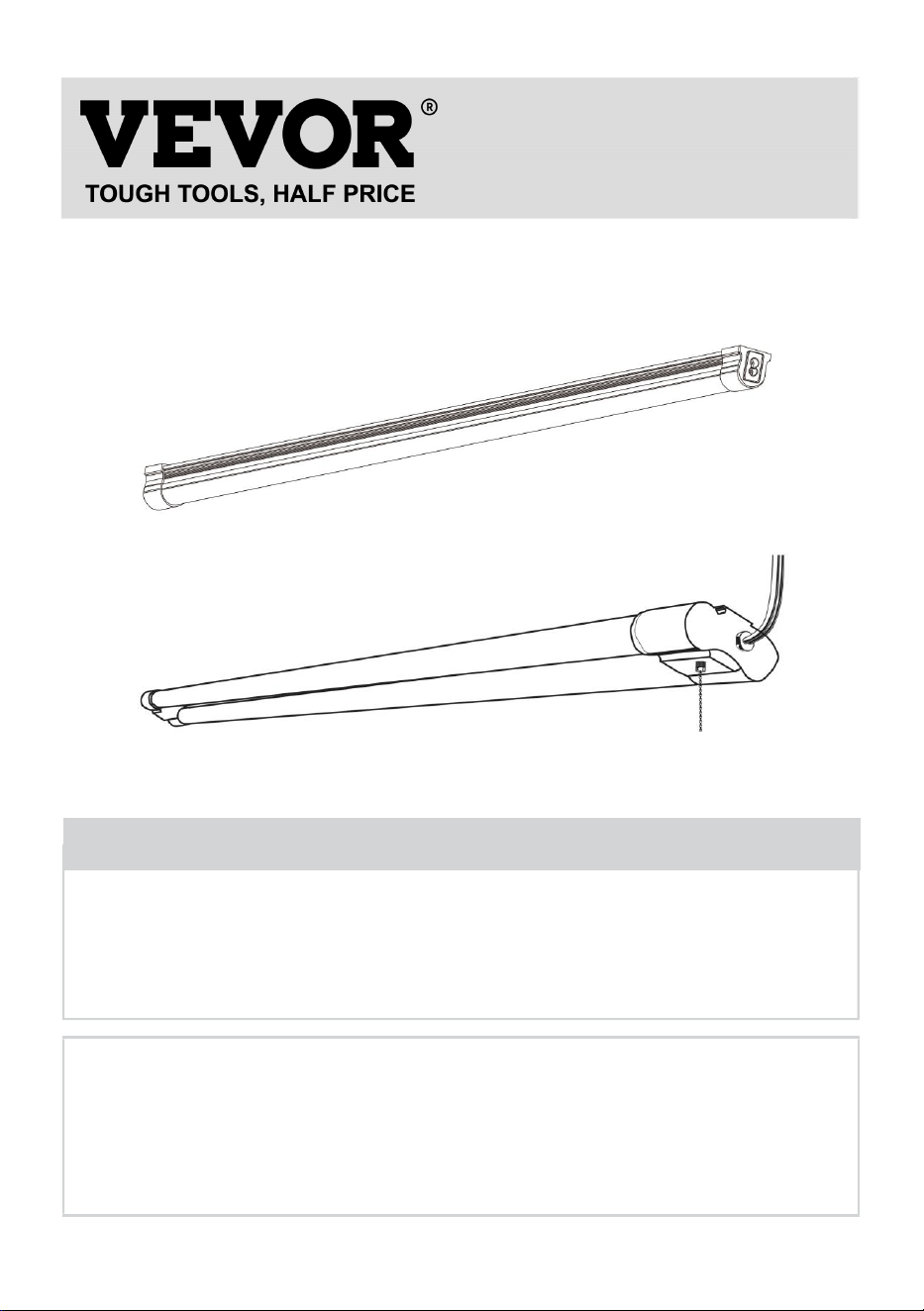
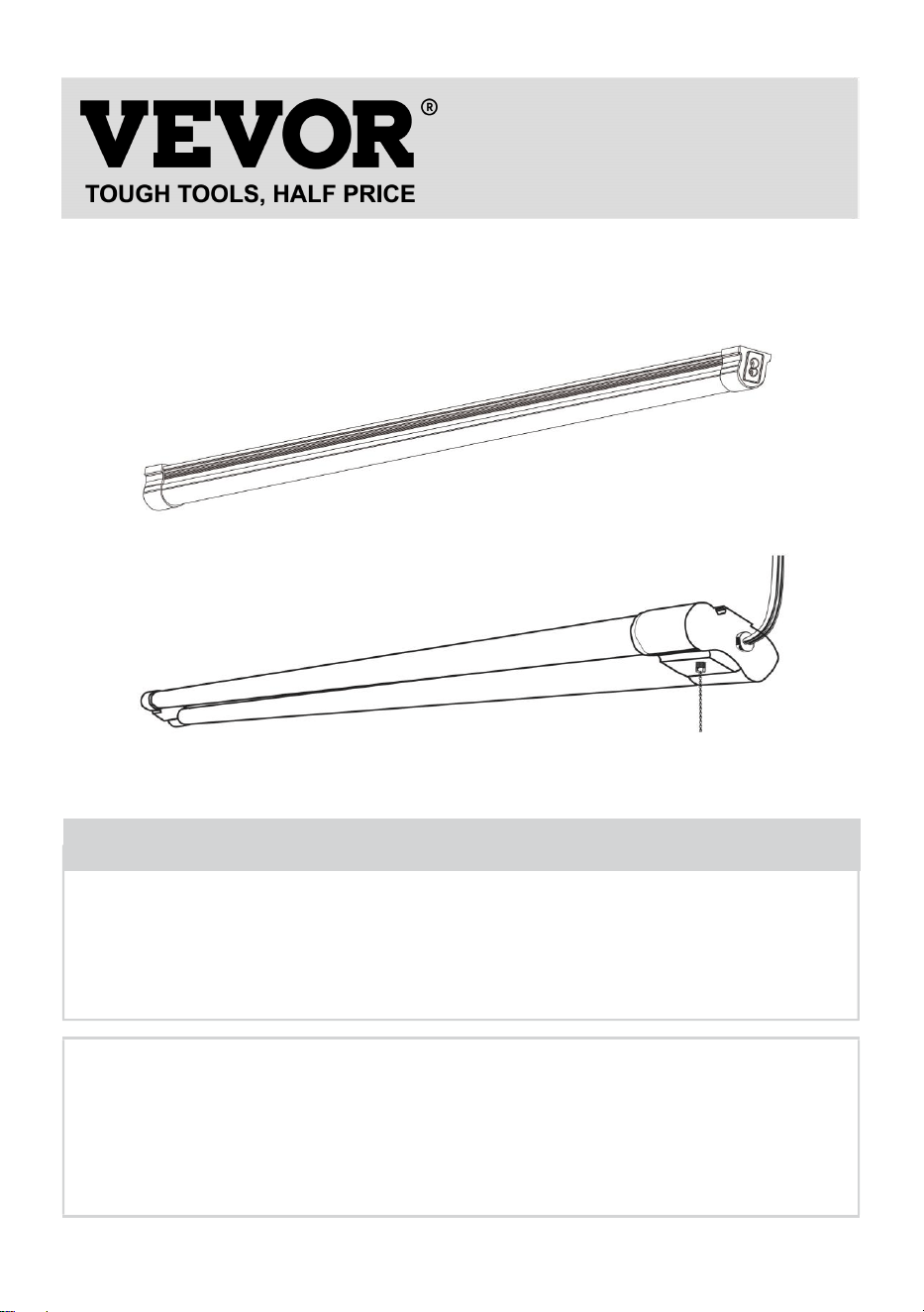
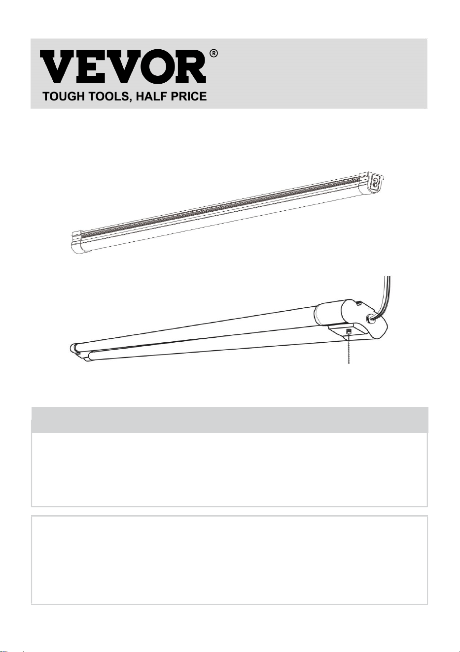
LED UTILITY SHOP LIGHT
INSTALLATION MANUAL
MODEL:GT-BZUX-40/GT-BZUX-80
GT-SLT-LK-3/GT-SLT-LK-4
We continue to be committed to provide you tools with competitive price.
"Save Half", "Half Price" or any other similar expressions used by us only represents an
estimate of savings you might benefit from buying certain tools with us compared to the major
top brands and does not necessarily mean to cover all categories of tools offered by us. You
are kindly reminded to verify carefully when you are placing an order with us if you are
actually saving half in comparison with the top major brands.
- 1 -
MODEL:GT-BZUX-40/GT-BZUX-80
GT-SLT-LK-3/GT-SLT-LK-4
Have product questions? Need technical support? Please feel free to
contact us:
Technical Support and E-Warranty Certificate
www.vevor.com/support
NEED HELP? CONTACT US!
This is the original instruction, please read all manual instructions
carefully before operating. VEVOR reserves a clear interpretation of our
user manual. The appearance of the product shall be subject to the
product you received. Please forgive us that we won't inform you again if
there are any technology or software updates on our product.
LED UTILITY SHOP LIGHT
GT-BZUX-40/GT-BZUX-80
GT-SLT-LK-3/GT-SLT-LK-4
- 2 -
Warning-To reduce the risk of injury, user must read
instructions manual carefully.
IMPORTANT SAFETY INSTRUCTIONS
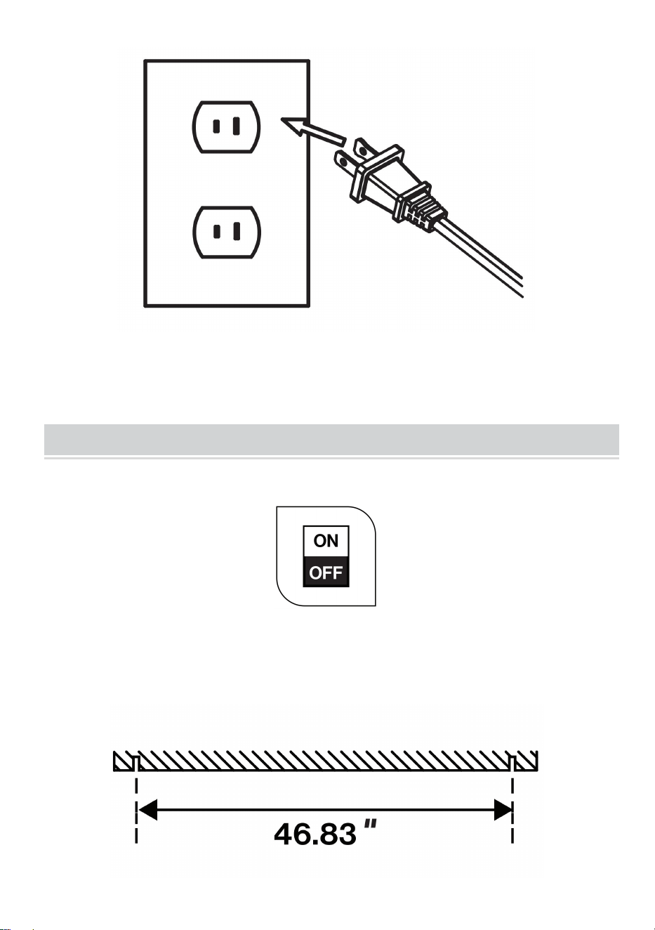
This fixture is to be installed directly beneath a ceiling-mounted receptacle.
This fixture has a polarized plug (one blade is wider than the other) as a feature
to reduce the risk of electric shock. This plug will only fit a polarized outlet one
way.
If the plug does not fully fit the outlet, reverse the plug. If it still does not fit,
contact a qualified electrician.
Do not use it with an extension cord unless the plug can be fully inserted.
Do not alter the plug.
SPECIFICATION PARAMETER
Table 1
Model
GT-BZUX-40
GT-BZUX-80
GT-SLT-LK-3
GT-SLT-LK-4
Input
120V~ 60Hz
120V~ 60Hz
120V~ 60Hz
120V~ 60Hz
Power
40W
80W
42W
42W
Tube Length
4FT
8FT
4FT
4FT
Luminance
5000(LM)
10000(LM)
4500(LM)
4500(LM)
Anti-interferenc
e function
Anti high
frequency and
anti RF
interference
Anti high
frequency and
anti RF
interference
Anti high
frequency and
anti RF
interference
Anti high
frequency and
anti RF
interference
light brightness
regulation
No
Three-gear
adjustments
(50%, 75%, and
100%)
Three-gear
adjustments
(50%, 75%, and
100%)
No
Max number of
series
6 PCS
4 PCS
6 PCS
6 PCS
Product
quantity
10 PCS
10 PCS
4 PCS
10 PCS
- 3 -
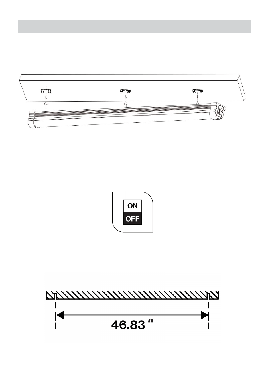
INSTALLATION INSTRUCTIONS
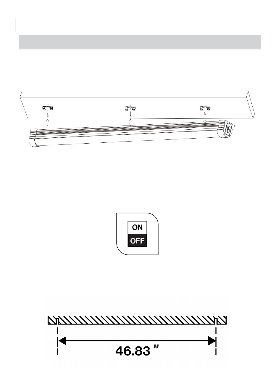
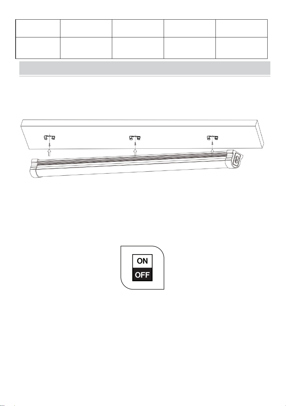
GT-BZUX-40/GT-BZUX-80 FLUSH MOUNT
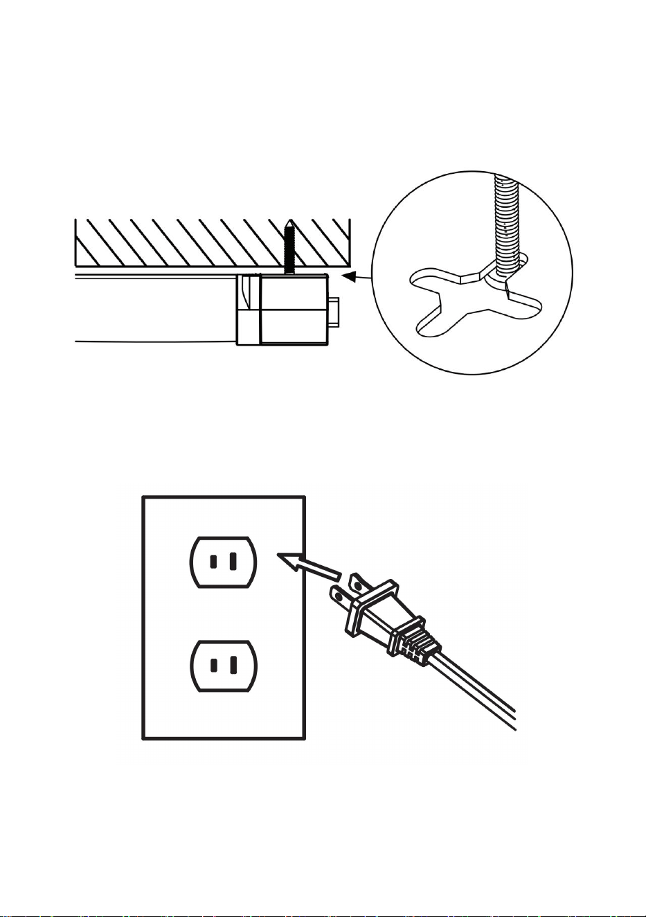
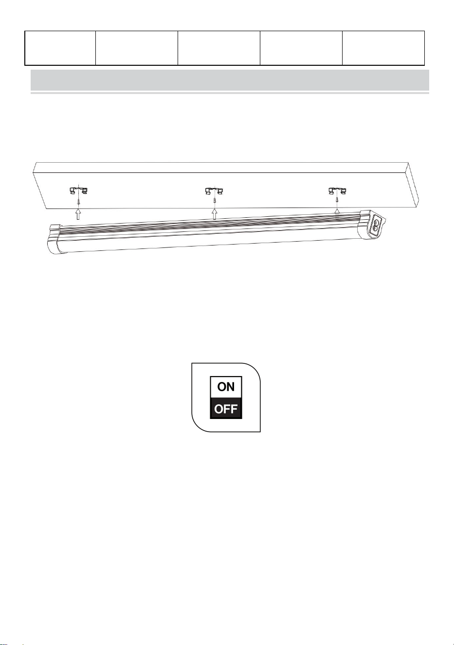
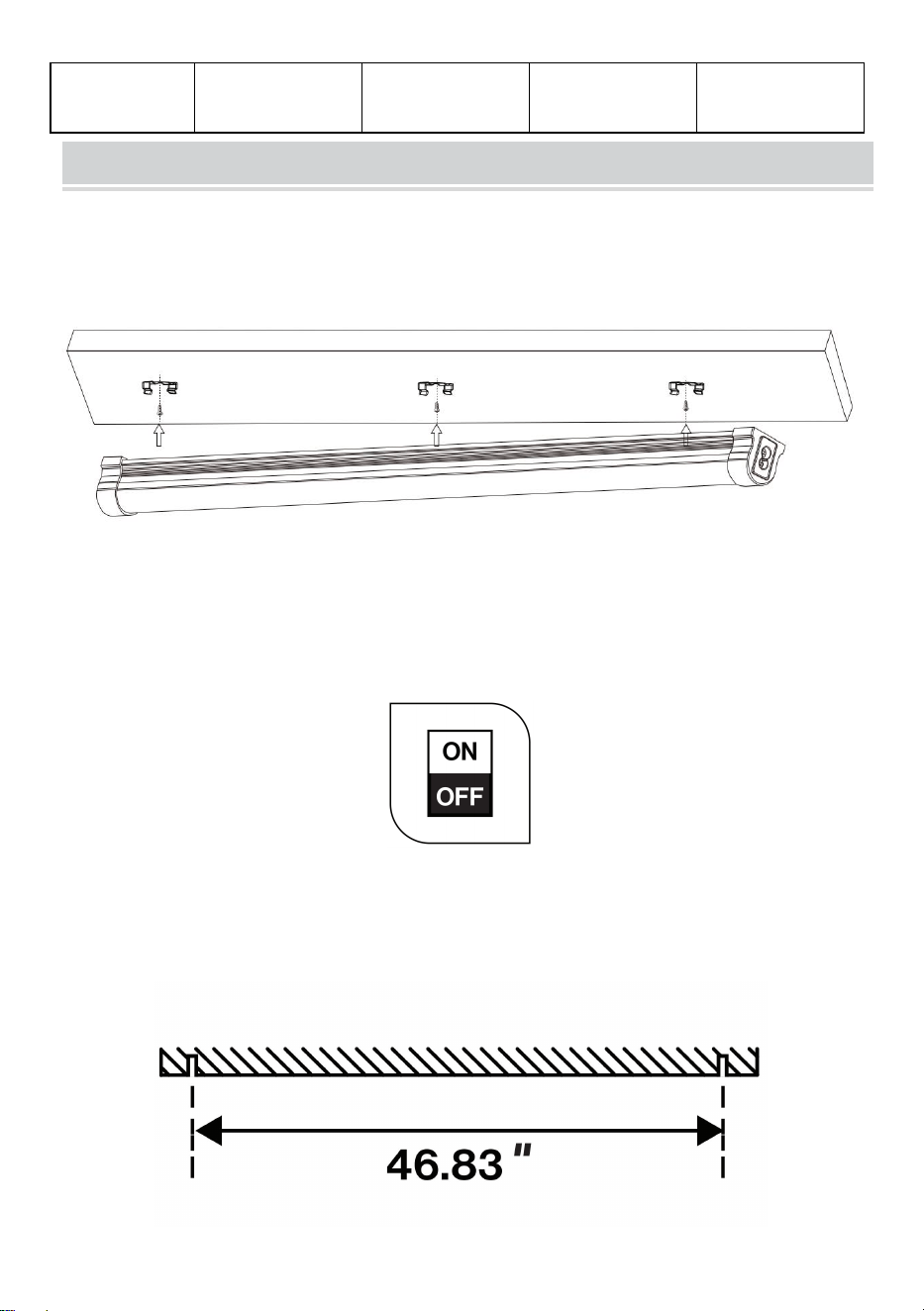
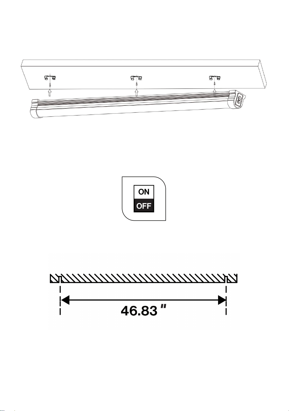
Fasten the buckle with screws and stick the LED light on the buckle
according to the arrow.
GT-SLT-LK-3/GT-SLT-LK-4 FLUSH MOUNT
1. Turn off the circuit breaker before installation.
CAUTION: The Mounting surface must be able to support weight of
fixture.
- 4 -
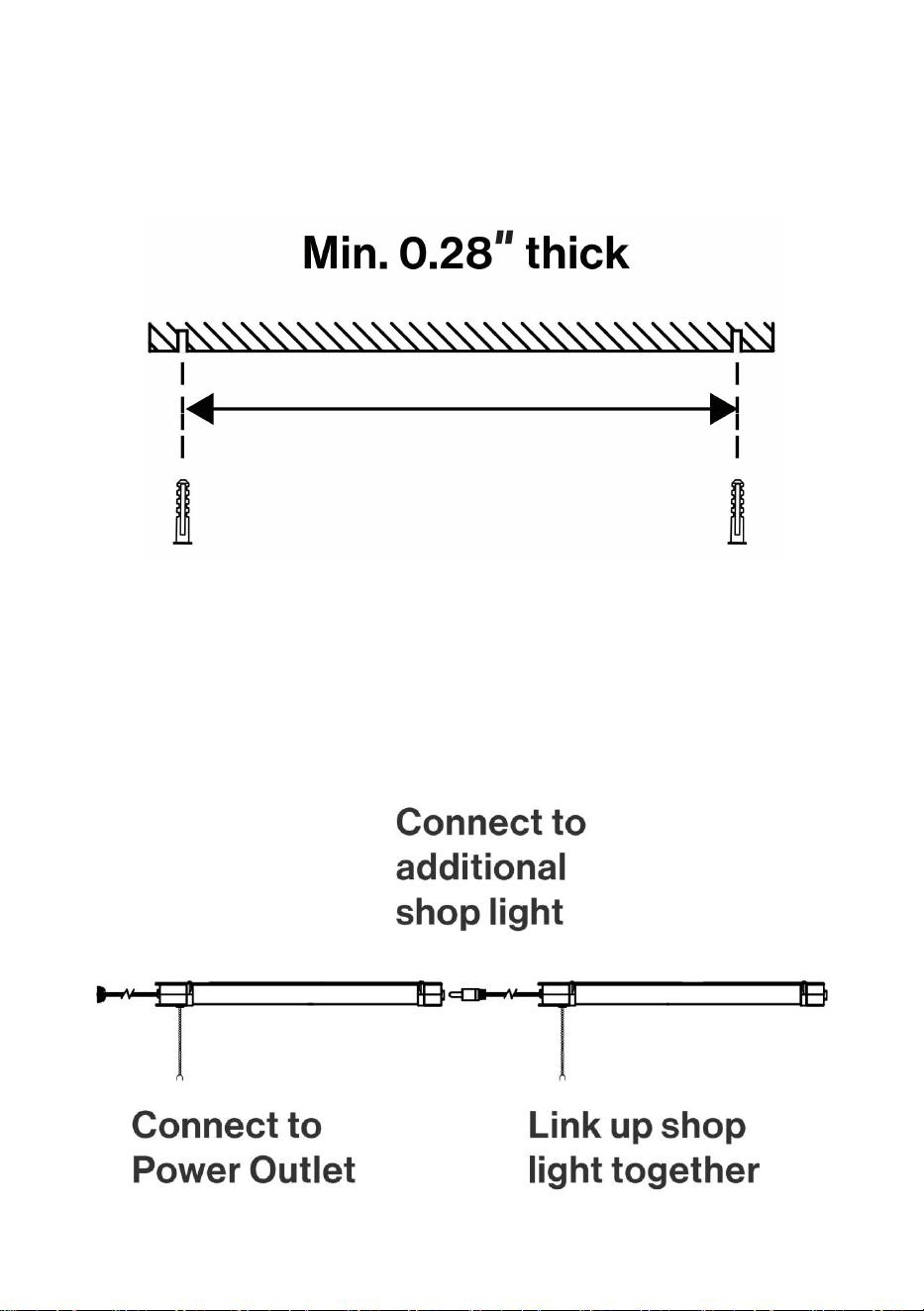
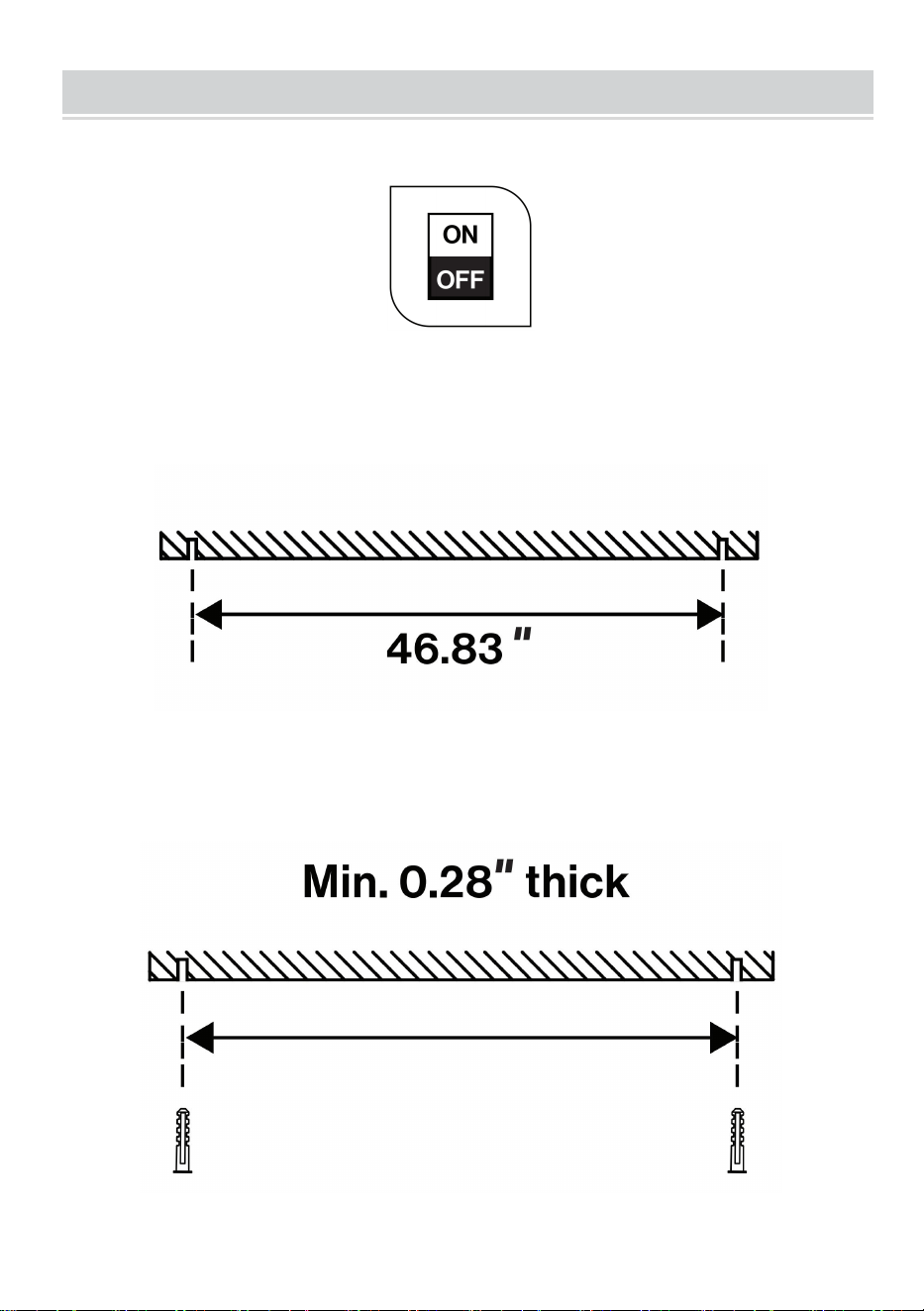
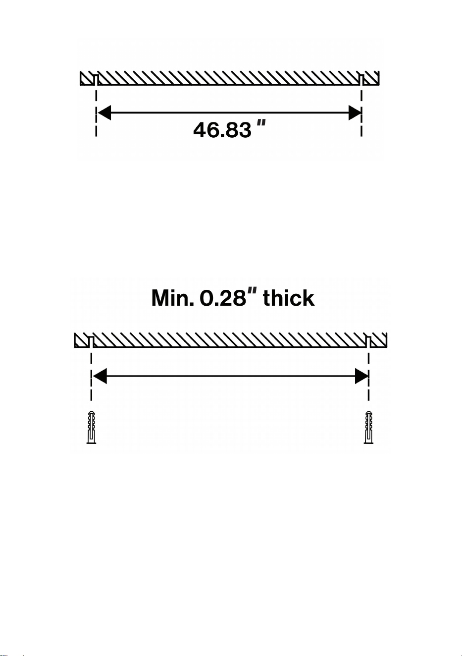
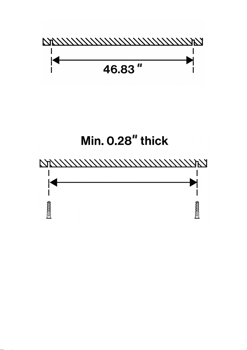
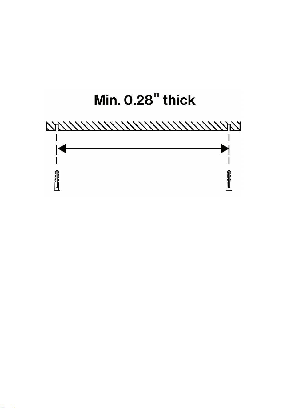
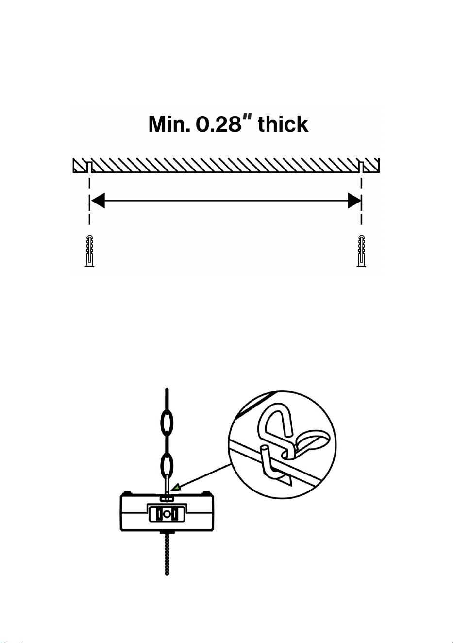
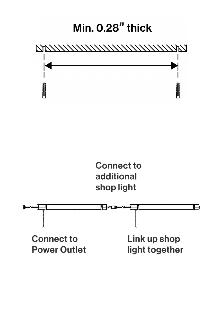
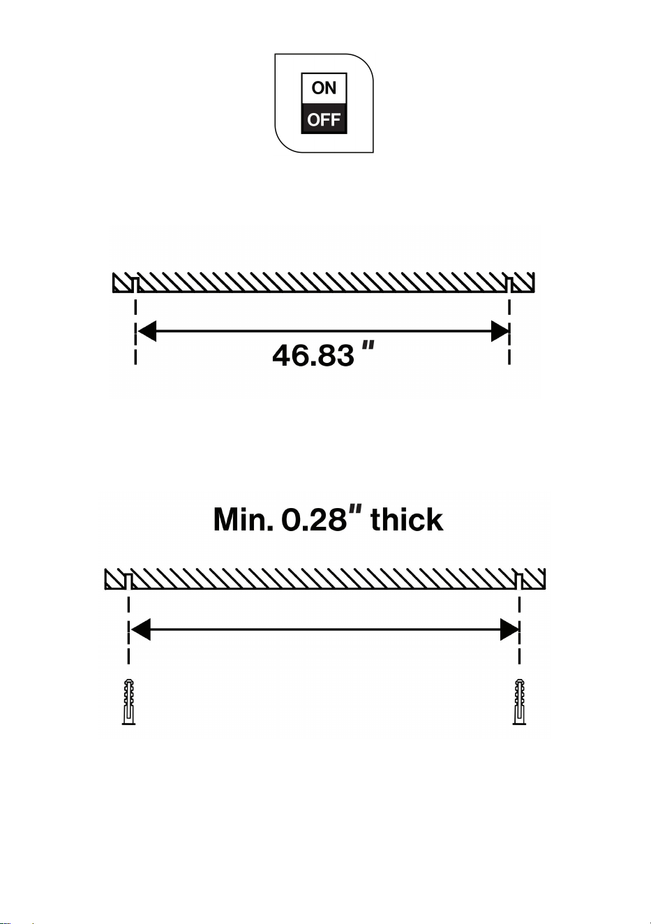
2. Drill 2 pilot holes into the ceiling. Holes should be 46.36 inches apart.
• Dry Wall: 7/32″ drill bit
• Wall Stud: 9/64″ drill bit
3. Insert expansion anchors into pilot holes.
4. Tighten screws into expansion anchors.
• Leave about 0.17″ gap between the screw heads and mounting
surface.
- 5 -
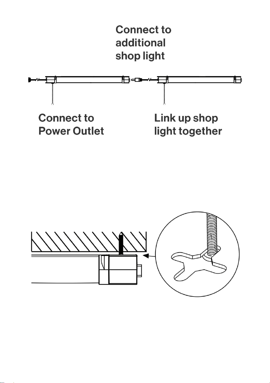
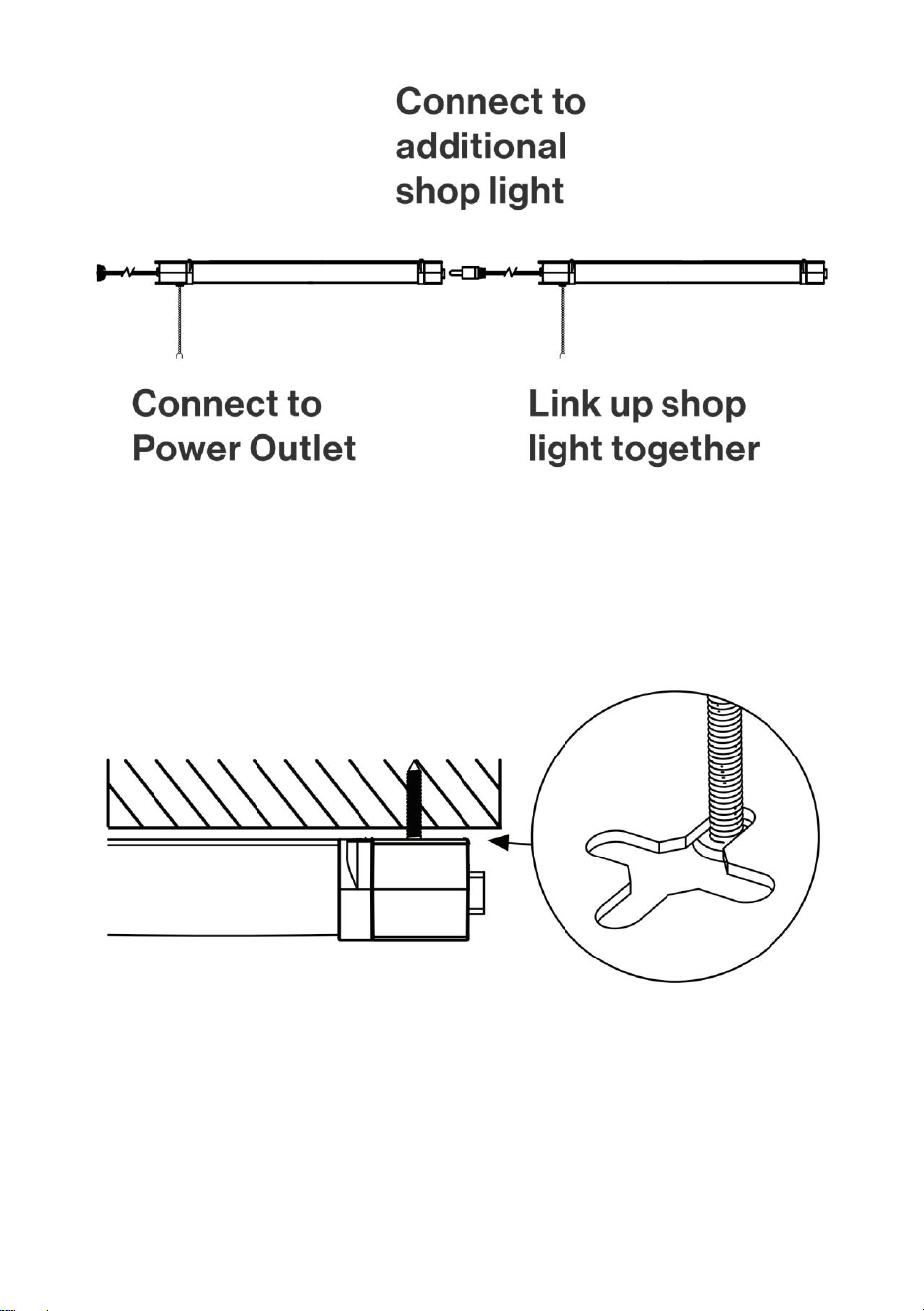
NOTE: Space fixture to suit your lighting plan and power chord length
(60″).
Connect the store lights together with a maximum number of
connections not exceeding the requirements in Table 1.
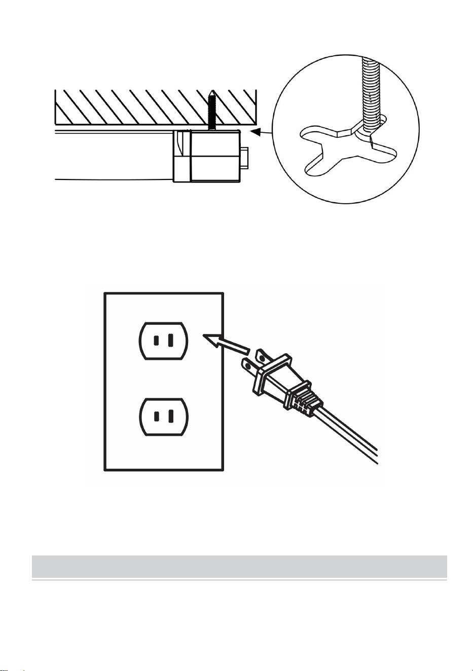
5. Align fixture to screws.
6. When holes are aligned, push fixture up.
• Slide to secure.
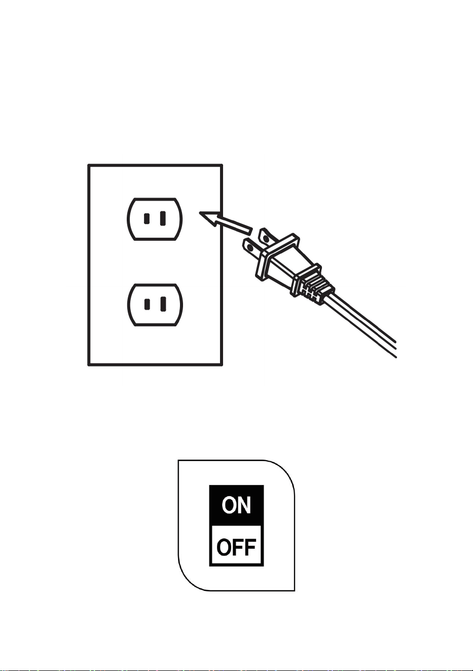
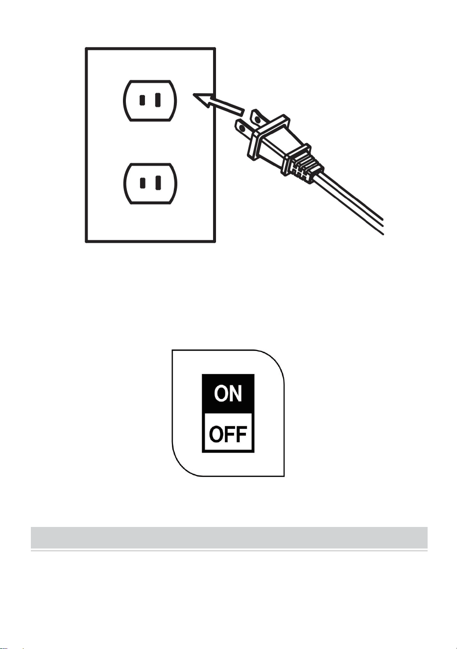
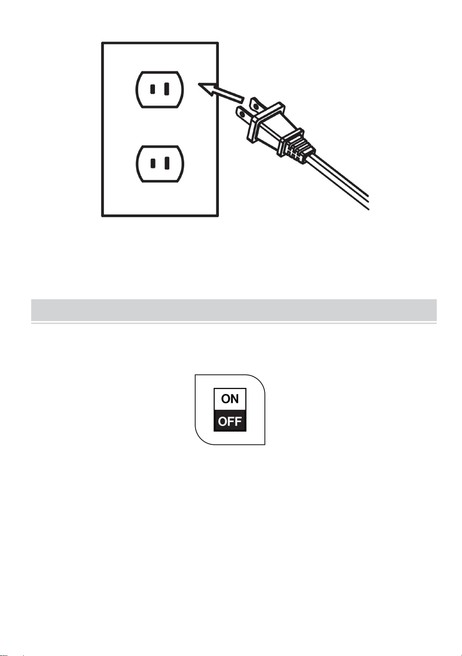
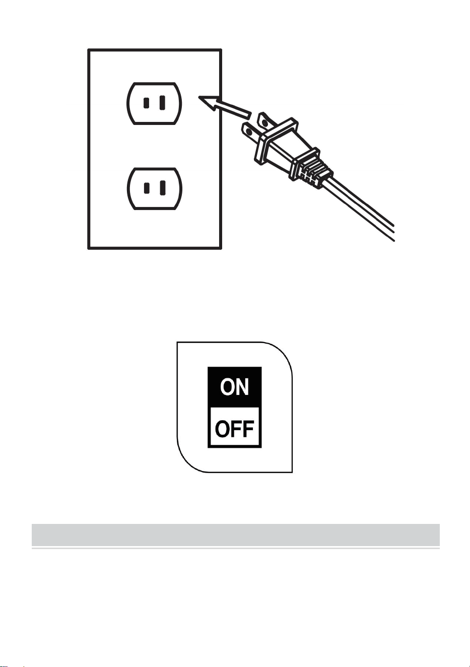
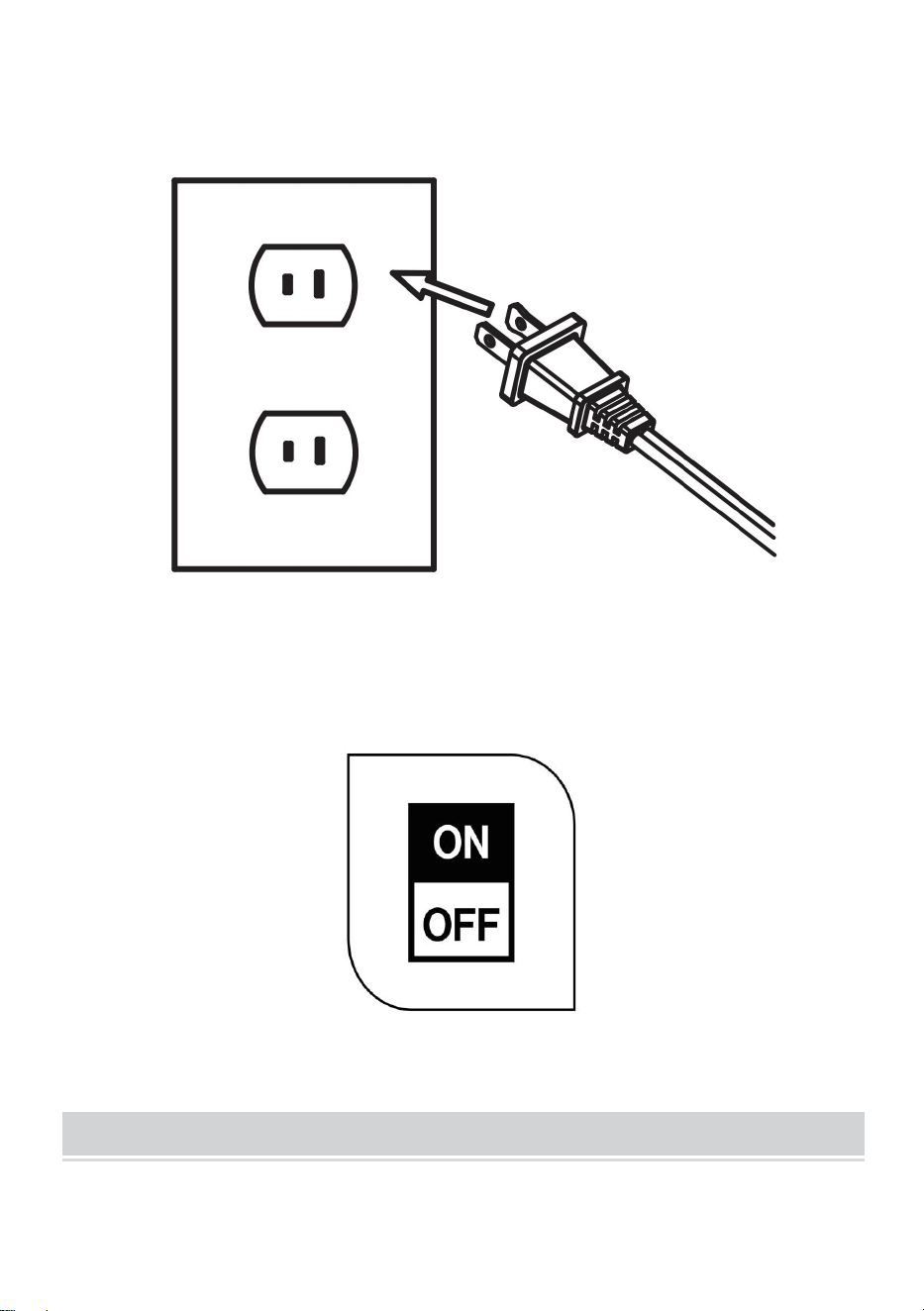
7. Plug in power cord to electrical outlet
8. Turn on circuit breaker and test light.
- 6 -
INSTALLATION INSTRUCTIONS
GT-SLT-LK-3/GT-SLT-LK-4 HANGING MOUNT
1. Turn off the circuit breaker before installation.
CAUTION: The Mounting surface must be able to support weight of
fixture.
2. Drill 2 pilot holes into the ceiling. Holes should be 46.36 inches apart.
• Dry Wall: 7/32″ drill bit.
• Wall Stud: 9/64″ drill bit.
- 7 -
3. Insert expansion anchors into pilot holes.
4. Tighten screws into expansion anchors.
• Leave about 0.17″ gap between the screw heads and mounting
surface.
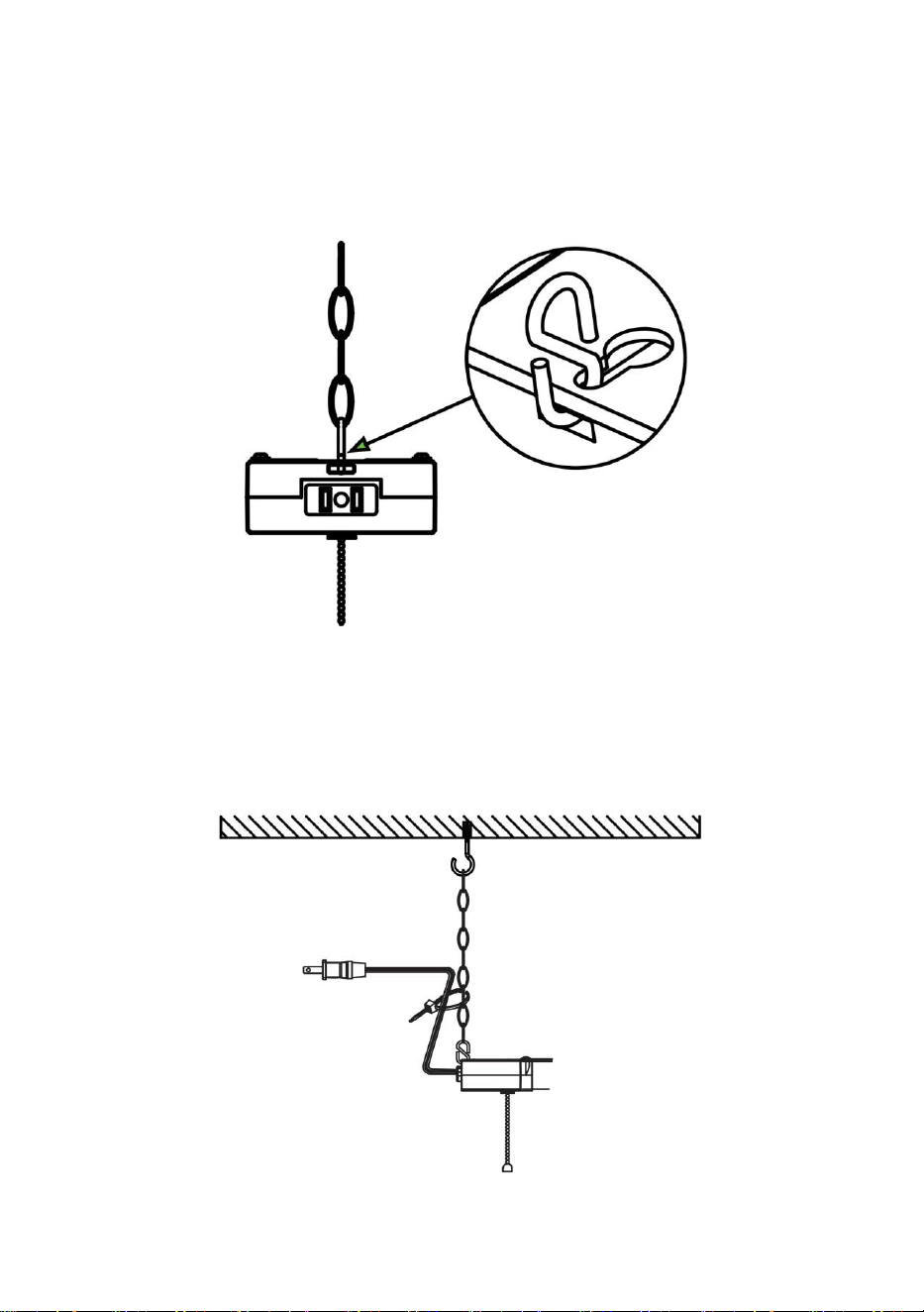
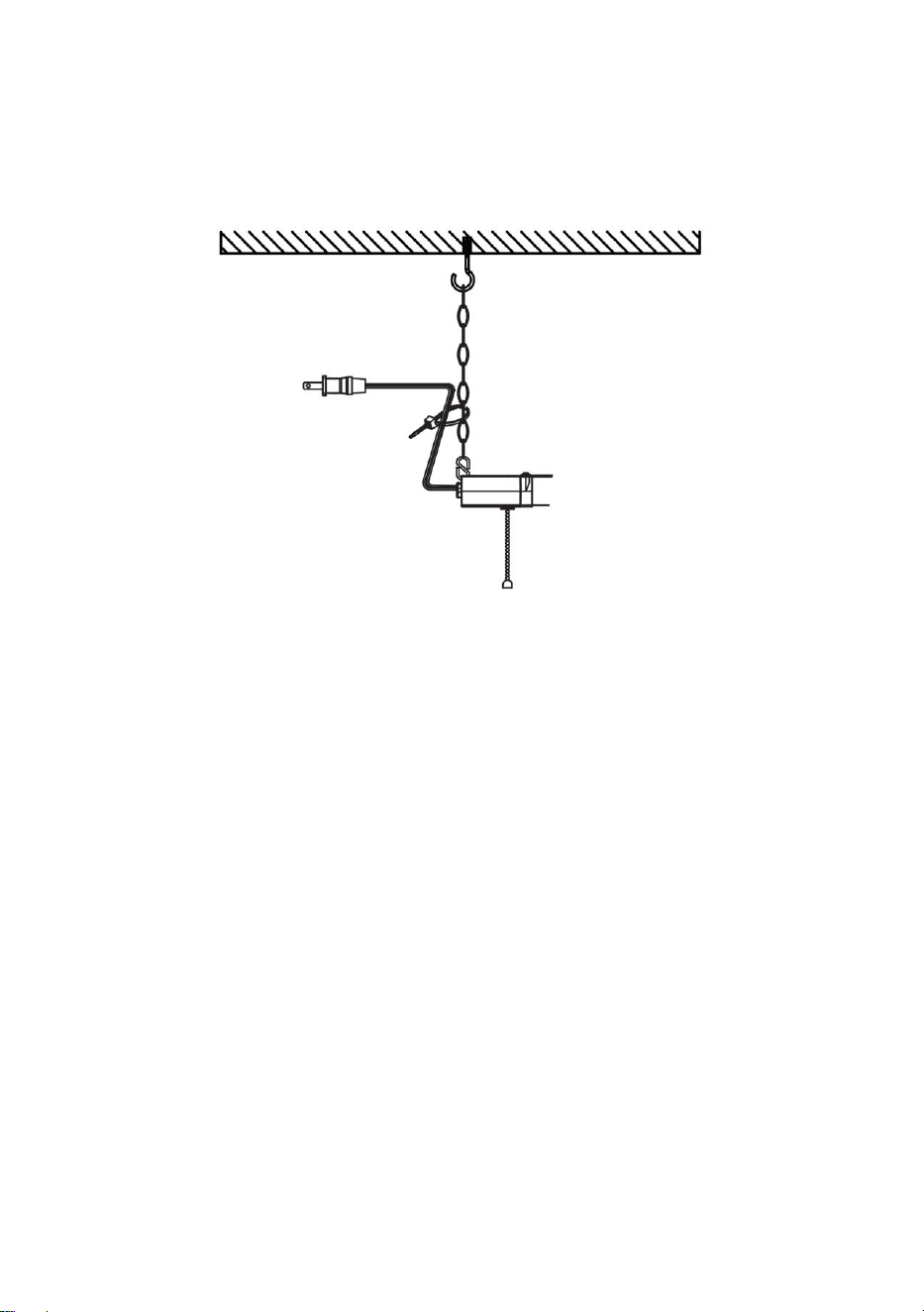
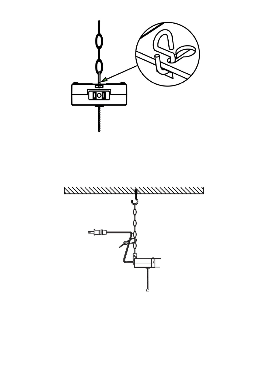
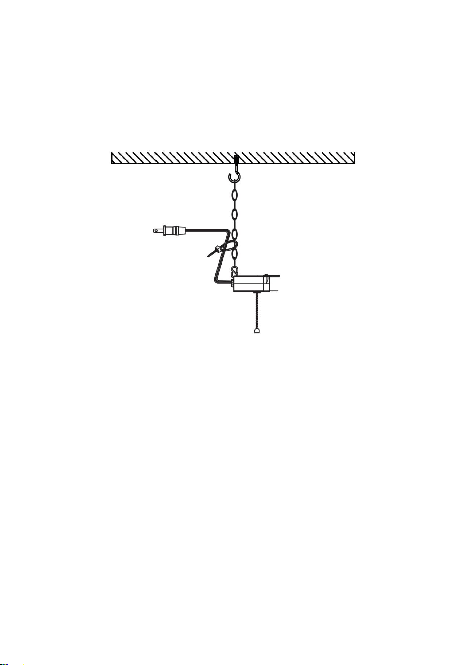
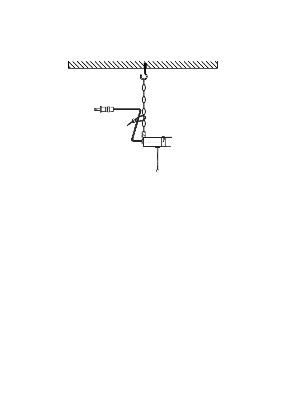
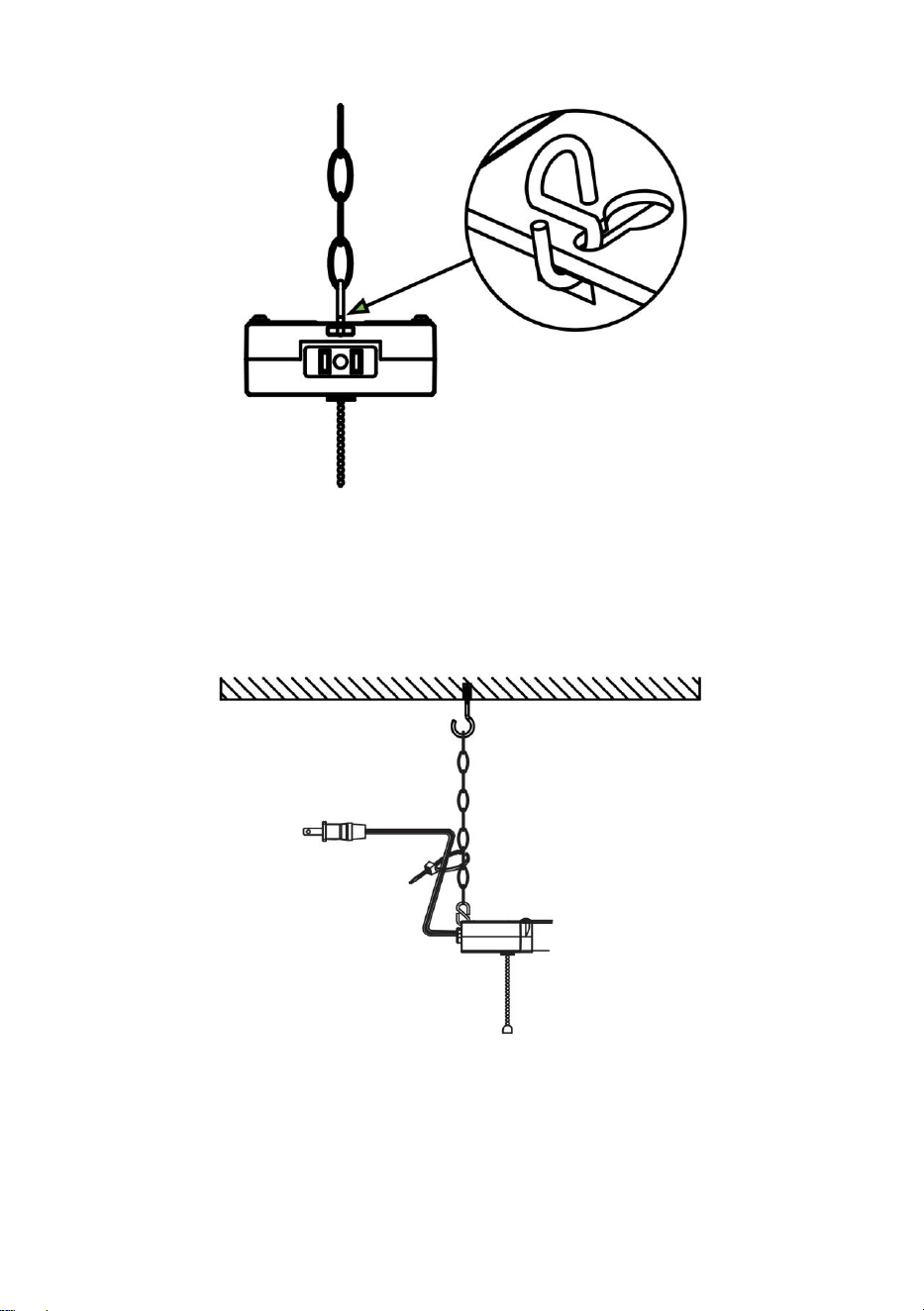
5. Insert S-hook into each end of mounting chains.
6. Loop other end of S-hooks into fixture’s keyhole slots.
• Crimp ends to secure.
- 8 -
7. Secure fixture to ceiling by hanging non-crimped portion of S-hooks
onto eye hooks.
• Adjust chain length as needed.
8. Secure fixture power cord to mounting chain using zip tie.
9. Plug in power cord to electrical outlet.
10. Turn on circuit breaker and test light.

- 9 -
WARNING
To reduce the risk of fire, electric shock, or injury:
• Turn off the circuit breaker before installing this fixture.
• This product should be installed by someone familiar with the
construction and operation of the product and the hazards involved. Safety
eyeglasses and gloves are recommended.
• Abide by related regional and local laws or regulations.
• Proper grounding is required to ensure safety.
• This fixture was designed for daisy chains only. Using it for other
purposes will void the warranty.
• Check for shipping damage before installing. If the product is damaged,
do not use it.
• Keep the fixture away from corrosive substances.
• Suitable for damp locations at temperatures ranging from 4°F to 113°F.
Not for use where directly exposed to water.
• Clean the fixture regularly to ensure proper operation. Do not clean with
harsh solvents.
• Use safety precautions and abide by regional and local laws or
regulations.
• This product is not compatible with 3rd party sensors or dimmers.
• This product is not compatible with photo controls.
• This product is not compatible with occupancy sensors.
• This product is not compatible with timing devices.
SAVE THESE INSTRUCTIONS
- 10 -
FAULT ANALYSIS
Questions
Analysis of causes
Countermeasure
The light is out
Whether the plug is
properly inserted.
1、Put the plug in place.
2、Check that the lights are
plugged in properly.
The lights will not
fit properly
Check whether
mounting holes and
clasps are correctly
installed.
Drill and install the holes
correctly according to the
required dimensions.
The lights are
dim.
Whether the voltage is
correct.
Use the right power source.


- 2 -
Technique Certificat d'assistance et de garantie électronique
www.vevor.com/support
ÉCLAIRAGE UTILITAIRE À LED POUR
MAGASIN
MANUEL D'INSTALLATION
MODÈLE : GT-BZUX-40 / GT-BZUX-80
GT-SLT-LK-3 / GT-SLT-LK-4
We continue to be committed to provide you tools with competitive price.
"Save Half", "Half Price" or any other similar expressions used by us only represents an
estimate of savings you might benefit from buying certain tools with us compared to the major
top brands and does not necessarily mean to cover all categories of tools offered by us. You
are kindly reminded to verify carefully when you are placing an order with us if you are
actually saving half in comparison with the top major brands.

- 3 -

- 1 -
MODÈLE : GT-BZUX-40 / GT-BZUX-80
GT-SLT-LK-3 / GT-SLT-LK-4
Have product questions? Need technical support? Please feel free to
contact us:
Technical Support and E-Warranty Certificate
www.vevor.com/support
NEED HELP? CONTACT US!
This is the original instruction, please read all manual instructions
carefully before operating. VEVOR reserves a clear interpretation of our
user manual. The appearance of the product shall be subject to the
product you received. Please forgive us that we won't inform you again if
there are any technology or software updates on our product.
LED UTILITY SHOP LIGHT
GT-BZUX-40/GT-BZUX-80
GT-SLT-LK-3/GT-SLT-LK-4
- 2 -
Avertissement - Pour réduire le risque de blessure,
l'utilisateur doit lire attentivement le manuel d'instructions.
IMPORTANT SAFETY INSTRUCTIONS
Ce luminaire doit être installé directement sous une prise de courant montée au
plafond.
Ce luminaire est doté d'une fiche polarisée (une lame est plus large que l'autre)
afin de réduire le risque de choc électrique. Cette fiche ne s'adapte à une
prise polarisée que dans un seul sens.
Si la fiche ne s'insère pas parfaitement dans la prise, inversez-la. Si elle ne
s'insère toujours pas, contactez un électricien qualifié.
Ne l'utilisez pas avec une rallonge, sauf si la fiche peut être complètement
insérée.
Ne pas modifier la prise.
SPECIFICATION PARAMETER
Tableau 1
Modèle
GT-BZUX-40
GT-BZUX-80
GT-SLT-LK-3
GT-SLT-LK-4
Saisir
120V ~ 60 Hz
120V ~ 60 Hz
120V ~ 60 Hz
120V ~ 60 Hz
Pouvoir
40 W
80 W
42W
42W
Longueur du
tube
4 pieds
8 pieds
4 pieds
4 pieds
Luminance
50 00 (LM)
1 0 000 (LM)
45 00 (LM)
45 00 (LM)
Fonction
anti-interférenc
e
Anti haute
fréquence et anti
interférence RF
Anti haute
fréquence et anti
interférence RF
Anti haute
fréquence et anti
interférence RF
Anti haute
fréquence et anti
interférence RF
régulation de la
luminosité de
la lumière
Non
trois vitesses
(50 % , 75 % et
100%)
trois vitesses
(50 % , 75 % et
100%)
Non
Nombre
maximum de
séries
6 pièces
4 pièces
6 pièces
6 pièces
- 3 -
Quantité de
produit
10 pièces
10 pièces
4 pièces
10 pièces
INSTALLATION INSTRUCTIONS
GT-BZUX-40 / GT-BZUX-80 MONTAGE ENCASTRÉ
Fixez la boucle avec des vis et collez la lumière LED sur la boucle selon la
flèche.
GT-SLT-LK-3 / GT-SLT-LK-4 MONTAGE ENCASTRÉ
9. Coupez le disjoncteur avant l'installation.
ATTENTION : La surface de montage doit pouvoir supporter le poids
du luminaire.

- 4 -
10. Percez 2 trous pilotes dans le plafond. Les trous doivent être espacés
de 46,36 pouces.
• Cloison sèche : foret de 7/32 po
• Montant mural : foret 9/64″
11.Insérez les ancrages à expansion dans les trous pilotes.
12. Serrez les vis dans les chevilles à expansion.
• Laissez un espace d’environ 0,17 po entre les têtes de vis et la
surface de montage.
- 5 -
REMARQUE : Adaptez l'espace à votre plan d'éclairage et à votre
puissance longueur de la corde (60″).
Connectez les lumières du magasin ensemble avec un nombre
maximum de connexions ne dépassant pas les exigences du tableau
1.
13. Alignez le luminaire sur les vis.
14. Lorsque les trous sont alignés, poussez le luminaire vers le haut.
• Faites glisser pour sécuriser.

- 6 -
15. Branchez le cordon d'alimentation sur la prise électrique
16. Allumez le disjoncteur et testez la lumière.
INSTALLATION INSTRUCTIONS
GT-SLT-LK-3 / GT-SLT-LK-4 SUPPORT SUSPENDU
11. Coupez le disjoncteur avant l'installation.
ATTENTION : La surface de montage doit pouvoir supporter le poids
du luminaire.

- 7 -
12. Percez 2 trous pilotes dans le plafond. Les trous doivent être espacés
de 46,36 pouces.
• Cloison sèche : foret 7/32″ .
• Montant mural : foret 9/64″ .
13. Insérez les ancrages à expansion dans les trous pilotes.
14. Serrez les vis dans les chevilles à expansion.
• Laissez un espace d’environ 0,17 po entre les têtes de vis et la
surface de montage.
15. Insérez le crochet en S à chaque extrémité des chaînes de montage.
- 8 -
16. Enroulez l'autre extrémité des crochets en S dans les fentes en trou de
serrure du luminaire.
• Sertir les extrémités pour sécuriser .
17. Fixez le luminaire au plafond en accrochant la partie non sertie des
crochets en S sur les crochets à œil.
• Ajustez la longueur de la chaîne selon vos besoins.
18. Sécurisé Cordon d'alimentation du luminaire à la chaîne de montage à
l'aide d'un serre-câble.
- 9 -
19. Branchez le cordon d’alimentation sur la prise électrique.
20. Allumez le disjoncteur et testez la lumière.
WARNING
Pour réduire le risque d’incendie, de choc électrique ou de blessure :
• Coupez le disjoncteur avant d’installer ce luminaire.
• Ce produit doit être installé par une personne connaissant la

- 10 -
construction et le fonctionnement du produit ainsi que les risques encourus.
Des lunettes de sécurité et des gants sont recommandés.
• Respectez les lois et réglementations régionales et locales en vigueur.
• Une mise à la terre appropriée est nécessaire pour assurer la sécurité.
• Ce luminaire a été conçu pour être monté en guirlande uniquement. Son
utilisation à d'autres fins annulera la garantie.
• Vérifiez qu'il n'y a pas de dommages dus au transport avant l'installation.
Si le produit est endommagé, ne l'utilisez pas.
• Gardez l’appareil à l’écart des substances corrosives.
• Convient aux endroits humides à des températures comprises entre 4°F
et 113°F. Ne pas utiliser en cas d'exposition directe à l'eau.
• Nettoyez régulièrement l'appareil pour garantir son bon fonctionnement.
Ne pas nettoyer avec des solvants agressifs.
• Utilisez des précautions de sécurité et respectez les lois ou
réglementations régionales et locales.
• Ce produit n'est pas compatible avec les capteurs ou variateurs tiers.
• Ce produit n'est pas compatible avec les commandes photos.
• Ce produit n'est pas compatible avec les capteurs de présence.
• Ce produit n'est pas compatible avec les appareils de chronométrage.
CONSERVEZ CES INSTRUCTIONS
FAULT ANALYSIS
Questions
Analyse des causes
Contre-mesure

- 11 -
La lumière est
éteinte
Si la fiche est
correctement insérée.
1、 Mettez le bouchon en
place.
2. Vérifiez que les lumières
sont correctement
branchées.
Les lumières ne
s'adapteront pas
correctement
Vérifiez si les trous de
montage et les fermoirs
sont correctement
installés .
Percez et installez les trous
correctement selon les
dimensions requises.
Les lumières sont
tamisées.
Si la tension est
correcte.
Utilisez la bonne source
d’alimentation.


- 2 -
Technisch Support und E-Garantie-Zertifikat www.vevor.com/support
LED-WERKSTATTLEUCHTE
INSTALLATIONSHANDBUCH
MODELL: GT-BZUX-40 / GT-BZUX-80
GT-SLT-LK-3 / GT-SLT-LK-4
We continue to be committed to provide you tools with competitive price.
"Save Half", "Half Price" or any other similar expressions used by us only represents an
estimate of savings you might benefit from buying certain tools with us compared to the major
top brands and does not necessarily mean to cover all categories of tools offered by us. You
are kindly reminded to verify carefully when you are placing an order with us if you are
actually saving half in comparison with the top major brands.

- 1 -
MODELL: GT-BZUX-40 / GT-BZUX-80
GT-SLT-LK-3 / GT-SLT-LK-4
Have product questions? Need technical support? Please feel free to
contact us:
Technical Support and E-Warranty Certificate
www.vevor.com/support
NEED HELP? CONTACT US!
This is the original instruction, please read all manual instructions
carefully before operating. VEVOR reserves a clear interpretation of our
user manual. The appearance of the product shall be subject to the
product you received. Please forgive us that we won't inform you again if
there are any technology or software updates on our product.
LED UTILITY SHOP LIGHT
GT-BZUX-40/GT-BZUX-80
GT-SLT-LK-3/GT-SLT-LK-4

- 2 -
Warnung: Um das Verletzungsrisiko zu verringern, muss der
Benutzer die Bedienungsanleitung sorgfältig lesen.
IMPORTANT SAFETY INSTRUCTIONS
Diese Vorrichtung ist direkt unter einer Deckensteckdose zu installieren.
Dieses Gerät verfügt über einen polarisierten Stecker (ein Stift ist breiter als der
andere), um das Risiko eines Stromschlags zu verringern. Dieser Stecker
passt nur auf eine Art in eine polarisierte Steckdose.
Wenn der Stecker nicht richtig in die Steckdose passt, drehen Sie den Stecker
um. Wenn er immer noch nicht passt, wenden Sie sich an einen qualifizierten
Elektriker.
Verwenden Sie es nicht mit einem Verlängerungskabel, es sei denn, der
Stecker lässt sich vollständig einstecken.
Den Stecker nicht verändern.
SPECIFICATION PARAMETER
Tabelle 1
Modell
GT-BZUX-40
GT-BZUX-80
GT-SLT-LK-3
GT-SLT-LK-4
Eingang
120 V ~ 60 Hz
120 V ~ 60 Hz
120 V ~ 60 Hz
120 V ~ 60 Hz
Leistung
40 W
80 W
42W
42W
Rohrlänge
4FT
8 Fuß
4FT
4FT
Leuchtdichte
50 00 (LM)
1 0 000 (LM)
45 00 (LM)
45 00 (LM)
Anti-Interferenz
-Funktion
Schutz vor
Hochfrequenz-
und
HF-Interferenzen
Schutz vor
Hochfrequenz-
und
HF-Interferenzen
Schutz vor
Hochfrequenz-
und
HF-Interferenzen
Schutz vor
Hochfrequenz-
und
HF-Störungen
Lichthelligkeitsr
egulierung
NEIN
Drei-Gang-Einstel
lungen (50% ,
75 % und 100 %)
Drei-Gang-Einstel
lungen (50% ,
75 % und 100 %)
NEIN
Maximale
Anzahl an
Serien
6 Stück
4 Stück
6 Stück
6 Stück
- 3 -
Produktmenge
10 STK
10 STK
4 Stück
10 STK
INSTALLATION INSTRUCTIONS
GT-BZUX-40 / GT-BZUX-80 BÜNDIGE MONTAGE
Befestigen Sie die Schnalle mit Schrauben und kleben Sie das LED-Licht
in Pfeilrichtung auf die Schnalle.
GT-SLT-LK-3 / GT-SLT-LK-4 BÜNDIGE MONTAGE
17. Schalten Sie vor der Installation den Schutzschalter aus.
ACHTUNG: Die Montagefläche muss das Gewicht der Vorrichtung
tragen können.

- 4 -
18. Bohren Sie zwei Führungslöcher in die Decke. Die Löcher sollten 118
cm voneinander entfernt sein.
• Trockenbau: 7/32″ Bohrer
• Wandpfosten: 9/64″ Bohrer
19. Setzen Sie Spreizanker in die Führungslöcher ein .
20. Schrauben Sie die Spreizdübel fest.
• Lassen Sie zwischen den Schraubenköpfen und der Montagefläche
einen Abstand von etwa 0,17 Zoll.

- 5 -
HINWEIS: Platzieren Sie die Leuchte passend zu Ihrem
Beleuchtungsplan und Ihrer Leistung Sehnenlänge (60″).
Verbinden Sie die Ladenleuchten mit einer maximalen Anzahl von
Verbindungen, die die Anforderungen in Tabelle 1 nicht
überschreitet.
21. Richten Sie die Vorrichtung an den Schrauben aus.
22. Wenn die Löcher ausgerichtet sind, drücken Sie die Vorrichtung nach
oben.
• Zum Sichern schieben.

- 6 -
23. Stecken Sie das Netzkabel in die Steckdose
24. Schalten Sie den Leistungsschalter ein und prüfen Sie die Lampe.
INSTALLATION INSTRUCTIONS
GT-SLT-LK-3 / GT-SLT-LK-4 HÄNGENDE MONTAGE
21. Schalten Sie vor der Installation den Schutzschalter aus.
ACHTUNG: Die Montagefläche muss das Gewicht der Vorrichtung
tragen können.

- 7 -
22. Bohren Sie zwei Führungslöcher in die Decke. Die Löcher sollten 118
cm voneinander entfernt sein.
• Trockenbau: 7/32″ Bohrer .
• Wandpfosten: 9/64″ Bohrer .
23. Setzen Sie Spreizanker in die Führungslöcher ein .
24. Schrauben Sie die Spreizdübel fest.
• Lassen Sie zwischen den Schraubenköpfen und der Montagefläche
einen Abstand von etwa 0,17 Zoll.
25. Stecken Sie in jedes Ende der Montageketten einen S-Haken.

- 8 -
26. Führen Sie das andere Ende der S-Haken in die Schlüssellochschlitze
der Vorrichtung ein.
• Zum Sichern die Enden fest crimpen .
27. Befestigen Sie die Vorrichtung an der Decke, indem Sie den nicht
gekräuselten Teil der S-Haken an den Ösenhaken hängen.
• Passen Sie die Kettenlänge nach Bedarf an.
28. Sicher Befestigen Sie das Netzkabel der Vorrichtung mit einem
Kabelbinder an der Montagekette.

- 9 -
29. Stecken Sie das Netzkabel in die Steckdose.
30. Schalten Sie den Leistungsschalter ein und prüfen Sie die Lampe.
WARNING
So verringern Sie das Risiko von Bränden, Stromschlägen oder
Verletzungen:
• Schalten Sie den Schutzschalter aus, bevor Sie dieses Gerät
installieren.

- 10 -
• Dieses Produkt sollte von jemandem installiert werden, der mit der
Konstruktion und Bedienung des Produkts sowie den damit verbundenen
Gefahren vertraut ist. Schutzbrille und Handschuhe werden empfohlen.
• Halten Sie die entsprechenden regionalen und lokalen Gesetze und
Vorschriften ein.
• Zur Gewährleistung der Sicherheit ist eine ordnungsgemäße Erdung
erforderlich.
• Dieses Gerät ist nur für Daisy-Chains konzipiert. Bei Verwendung für
andere Zwecke erlischt die Garantie.
• Überprüfen Sie das Produkt vor der Installation auf Transportschäden.
Wenn das Produkt beschädigt ist, verwenden Sie es nicht.
• Halten Sie das Gerät von ätzenden Substanzen fern.
• Geeignet für feuchte Standorte bei Temperaturen von -15 °C bis 45 °C.
Nicht für den Einsatz an Orten mit direktem Wasserkontakt geeignet.
• Reinigen Sie das Gerät regelmäßig, um einen ordnungsgemäßen
Betrieb sicherzustellen. Verwenden Sie keine scharfen Lösungsmittel zum
Reinigen.
• Treffen Sie Sicherheitsvorkehrungen und halten Sie sich an regionale
und lokale Gesetze und Vorschriften.
• Dieses Produkt ist nicht mit Sensoren oder Dimmern von Drittanbietern
kompatibel.
• Dieses Produkt ist nicht mit Fotosteuerungen kompatibel.
• Dieses Produkt ist nicht mit Belegungssensoren kompatibel.
• Dieses Produkt ist nicht mit Zeitmessgeräten kompatibel.
BEWAHREN SIE DIESE ANWEISUNGEN AUF

- 11 -
FAULT ANALYSIS
Fragen
Ursachenanalyse
Gegenmaßnahme
Das Licht ist aus
Ob der Stecker richtig
eingesteckt ist.
1. Stecken Sie den Stecker
ein.
2. Überprüfen Sie, ob die
Lichter richtig eingesteckt
sind.
Die Lichter
passen nicht
richtig
Prüfen Sie, ob die
Befestigungslöcher und
Klammern richtig
angebracht sind .
Bohren und montieren Sie
die Löcher fachgerecht
nach den erforderlichen
Maßen.
Die Lichter sind
schwach.
Ob die Spannung
stimmt.
Verwenden Sie die richtige
Stromquelle.


- 2 -
Tecnico Supporto e certificato di garanzia elettronica www.vevor.com/support
LUCE PER NEGOZI DI UTILITÀ A LED
MANUALE DI INSTALLAZIONE
MODELLO: GT-BZUX-40 / GT-BZUX-80
MODELLO GT-SLT-LK-3 / MODELLO GT-SLT-LK-4
We continue to be committed to provide you tools with competitive price.
"Save Half", "Half Price" or any other similar expressions used by us only represents an
estimate of savings you might benefit from buying certain tools with us compared to the major
top brands and does not necessarily mean to cover all categories of tools offered by us. You
are kindly reminded to verify carefully when you are placing an order with us if you are
actually saving half in comparison with the top major brands.
- 1 -
MODELLO: GT-BZUX-40 / GT-BZUX-80
MODELLO GT-SLT-LK-3 / MODELLO GT-SLT-LK-4
Have product questions? Need technical support? Please feel free to
contact us:
Technical Support and E-Warranty Certificate
www.vevor.com/support
NEED HELP? CONTACT US!
This is the original instruction, please read all manual instructions
carefully before operating. VEVOR reserves a clear interpretation of our
user manual. The appearance of the product shall be subject to the
product you received. Please forgive us that we won't inform you again if
there are any technology or software updates on our product.
LED UTILITY SHOP LIGHT
GT-BZUX-40/GT-BZUX-80
GT-SLT-LK-3/GT-SLT-LK-4
- 2 -
Attenzione: per ridurre il rischio di lesioni, l'utente deve
leggere attentamente il manuale di istruzioni.
IMPORTANT SAFETY INSTRUCTIONS
Questo apparecchio deve essere installato direttamente sotto una presa
montata sul soffitto.
Questo apparecchio ha una spina polarizzata (una lama è più larga dell'altra)
come caratteristica per ridurre il rischio di scosse elettriche. Questa spina si
adatta a una presa polarizzata solo in un modo.
Se la spina non si adatta completamente alla presa, inverti la spina. Se ancora
non si adatta, contatta un elettricista qualificato.
Non utilizzarlo con una prolunga a meno che la spina non possa essere inserita
completamente.
Non modificare la spina.
SPECIFICATION PARAMETER
Tabella 1
Modello
Modello
GT-BZUX-40
Modello
GT-BZUX-80
GT-SLT-LK-3
GT-SLT-LK-4
Ingresso
120V ~ 60 Hz
120V ~ 60 Hz
120V ~ 60 Hz
120V ~ 60 Hz
Energia
40W
80W
42W
42W
Lunghezza del
tubo
4 piedi
8 piedi
4 piedi
4 piedi
L uminosità
50 00 (LM)
1 0 000 (LM)
45 00 (LM)
45 00 (LM)
Funzione
anti-interferenz
a
Anti alta
frequenza e anti
interferenza RF
Anti alta
frequenza e anti
interferenza RF
Anti alta
frequenza e anti
interferenza RF
Anti alta
frequenza e anti
interferenza RF
regolazione
della
luminosità
della luce
NO
Regolazioni a tre
marce (50% ,
75 % e 100%)
Regolazioni a tre
marce (50% ,
75 % e 100%)
NO
Numero
massimo di
6 PZ
4 PZ
6 PZ
6 PZ
- 3 -
serie
Quantità del
prodotto
10 PZ
10 PZ
4 PZ
10 PZ
INSTALLATION INSTRUCTIONS
Modello GT-BZUX-40 / Modello GT-BZUX-80 MONTAGGIO A FILO
Fissare la fibbia con le viti e attaccare la luce LED sulla fibbia seguendo la
direzione della freccia.
Modello GT-SLT-LK-3 / Modello GT-SLT-LK-4 MONTAGGIO A FILO
25. Spegnere l'interruttore automatico prima dell'installazione.
ATTENZIONE: la superficie di montaggio deve essere in grado di
sostenere il peso dell'apparecchio.
- 4 -
26. Praticare 2 fori pilota nel soffitto . I fori devono essere distanti 46,36
pollici.
• Muro a secco: punta da trapano da 7/32″
• Perno a parete: punta da trapano da 9/64″
27. Inserire i tasselli ad espansione nei fori pilota.
28. Serrare le viti nei tasselli ad espansione.
• Lasciare circa 0,17″ di spazio tra le teste delle viti e la superficie di
montaggio.

- 5 -
NOTA: posizionare l'apparecchio in base al piano di illuminazione e
alla potenza lunghezza della corda (60″).
Collegare tra loro le luci del negozio con un numero massimo di
collegamenti che non superi i requisiti della Tabella 1.
29. Allineare l'apparecchio alle viti.
30. Una volta allineati i fori, spingere il dispositivo verso l'alto.
• Far scorrere per fissare.
- 6 -
31. Collegare il cavo di alimentazione alla presa elettrica
32. Accendere l'interruttore automatico e la spia di prova.
INSTALLATION INSTRUCTIONS
Modello GT-SLT-LK-3 / Modello GT-SLT-LK-4 SUPPORTO A
SOSPENSIONE
31. Spegnere l'interruttore automatico prima dell'installazione.
ATTENZIONE: la superficie di montaggio deve essere in grado di
sostenere il peso dell'apparecchio.
- 7 -
32. Praticare 2 fori pilota nel soffitto . I fori devono essere distanti 46,36
pollici.
• Muro a secco: punta da trapano da 7/32″ .
• Perno a parete: punta da trapano da 9/64″ .
33. Inserire i tasselli ad espansione nei fori pilota.
34. Serrare le viti nei tasselli ad espansione.
• Lasciare circa 0,17″ di spazio tra le teste delle viti e la superficie di
montaggio.
- 8 -
35. Inserire il gancio a S in ciascuna estremità delle catene di montaggio.
36. Inserire l'altra estremità dei ganci a S nelle fessure della struttura.
• Crimpare le estremità per fissarle .
37. Fissare l'apparecchio al soffitto appendendo la parte non crimpata dei
ganci a S ai ganci ad occhiello.
• Regolare la lunghezza della catena secondo necessità.
38. Sicuro cavo di alimentazione dell'apparecchio alla catena di
montaggio mediante fascetta.

- 9 -
39. Collegare il cavo di alimentazione alla presa elettrica.
40. Accendere l'interruttore automatico e la spia di prova.
WARNING
Per ridurre il rischio di incendi, scosse elettriche o lesioni:
• Spegnere l'interruttore automatico prima di installare questo

- 10 -
apparecchio.
• Questo prodotto deve essere installato da qualcuno che abbia familiarità
con la costruzione e il funzionamento del prodotto e con i pericoli connessi.
Si raccomandano occhiali e guanti di sicurezza.
• Rispettare le leggi e i regolamenti regionali e locali in materia.
• Per garantire la sicurezza è necessaria una corretta messa a terra.
• Questo dispositivo è stato progettato solo per daisy chain. Usarlo per
altri scopi invaliderà la garanzia.
• Controllare eventuali danni causati dalla spedizione prima
dell'installazione. Se il prodotto è danneggiato, non utilizzarlo.
• Tenere l'apparecchio lontano da sostanze corrosive.
• Adatto per luoghi umidi a temperature comprese tra 4°F e 113°F. Non
utilizzare in luoghi esposti direttamente all'acqua.
• Pulire regolarmente l'apparecchio per garantirne il corretto
funzionamento. Non pulire con solventi aggressivi.
• Adottare misure di sicurezza e attenersi alle leggi e ai regolamenti
regionali e locali.
• Questo prodotto non è compatibile con sensori o dimmer di terze parti.
• Questo prodotto non è compatibile con i controlli fotografici.
• Questo prodotto non è compatibile con i sensori di presenza.
• Questo prodotto non è compatibile con i dispositivi di cronometraggio.
SALVA QUESTE ISTRUZIONI
FAULT ANALYSIS

- 11 -
Domande
Analisi delle cause
Contromisura
La luce è spenta
Se la spina è inserita
correttamente.
1. Inserire la spina.
2. Controllare che le luci
siano collegate
correttamente.
Le luci non si
adatteranno
correttamente
Controllare che i fori di
montaggio e le chiusure
siano installati
correttamente .
Forare e installare
correttamente i fori in base
alle dimensioni richieste.
Le luci sono
fioche.
Se la tensione è
corretta.
Utilizzare la giusta fonte di
energia.


- 2 -
Técnico Soporte y certificado de garantía electrónica www.vevor.com/support
LUZ LED PARA TALLERES DE
UTILIDADES
MANUAL DE INSTALACIÓN
MODELO: GT-BZUX-40 / GT-BZUX-80
GT-SLT-LK-3 / GT-SLT-LK-4
We continue to be committed to provide you tools with competitive price.
"Save Half", "Half Price" or any other similar expressions used by us only represents an
estimate of savings you might benefit from buying certain tools with us compared to the major
top brands and does not necessarily mean to cover all categories of tools offered by us. You
are kindly reminded to verify carefully when you are placing an order with us if you are
actually saving half in comparison with the top major brands.

- 3 -

- 1 -
MODELO: GT-BZUX-40 / GT-BZUX-80
GT-SLT-LK-3 / GT-SLT-LK-4
Have product questions? Need technical support? Please feel free to
contact us:
Technical Support and E-Warranty Certificate
www.vevor.com/support
NEED HELP? CONTACT US!
This is the original instruction, please read all manual instructions
carefully before operating. VEVOR reserves a clear interpretation of our
user manual. The appearance of the product shall be subject to the
product you received. Please forgive us that we won't inform you again if
there are any technology or software updates on our product.
LED UTILITY SHOP LIGHT
GT-BZUX-40/GT-BZUX-80
GT-SLT-LK-3/GT-SLT-LK-4

- 2 -
Advertencia: Para reducir el riesgo de lesiones, el usuario
debe leer atentamente el manual de instrucciones.
IMPORTANT SAFETY INSTRUCTIONS
Este accesorio debe instalarse directamente debajo de un receptáculo
montado en el techo.
Este artefacto tiene un enchufe polarizado (una clavija es más ancha que la
otra) como característica para reducir el riesgo de descarga eléctrica. Este
enchufe solo encaja en un tomacorriente polarizado de una manera.
Si el enchufe no encaja completamente en el tomacorriente, invierta el enchufe.
Si sigue sin encajar, comuníquese con un electricista calificado.
No lo utilice con un cable de extensión a menos que el enchufe pueda
insertarse completamente.
No altere el enchufe.
SPECIFICATION PARAMETER
Tabla 1
Modelo
GT-BZUX-40
GT-BZUX-80
GT-SLT-LK-3
GT-SLT-LK-4
Aporte
120 V ~ 60 Hz
120 V ~ 60 Hz
120 V ~ 60 Hz
120 V ~ 60 Hz
Fuerza
40 W
80 W
42 W
42 W
Longitud del
tubo
4 pies
8 pies
4 pies
4 pies
Luminancia
50 00 (LM)
10 000 (LM)
45 00 (LM)
45 00 (LM)
Función
antiinterferenci
as
Anti alta
frecuencia y anti
interferencias RF
Anti alta
frecuencia y anti
interferencias RF
Anti alta
frecuencia y anti
interferencias RF
Anti alta
frecuencia y anti
interferencias RF
regulación del
brillo de la luz
No
de tres
velocidades
(50% , 75% y
100%)
de tres
velocidades
(50% , 75% y
100%)
No
Número
máximo de
series
6 piezas
4 piezas
6 piezas
6 piezas
- 3 -
Cantidad de
producto
10 piezas
10 piezas
4 piezas
10 piezas
INSTALLATION INSTRUCTIONS
GT-BZUX-40 / GT-BZUX-80 MONTAJE EMPOTRADO
Fije la hebilla con tornillos y pegue la luz LED en la hebilla según la flecha.
GT-SLT-LK-3 / GT-SLT-LK-4 MONTAJE EMPOTRADO
33. Apague el disyuntor antes de la instalación.
PRECAUCIÓN: La superficie de montaje debe poder soportar el peso
del accesorio.

- 4 -
34. Perfore dos orificios guía en el techo. Los orificios deben estar a 46,36
pulgadas de distancia entre sí.
• Paneles de yeso: broca de 7/32″
• Perno de pared: broca de 9/64″
35. Inserte anclajes de expansión en los orificios piloto.
36. Apriete los tornillos en los anclajes de expansión.
• Deje un espacio de aproximadamente 0,17″ entre las cabezas de los
tornillos y la superficie de montaje.

- 5 -
NOTA: Coloque el accesorio en el espacio que se adapte a su plan de
iluminación y potencia. longitud de la cuerda (60″).
Conecte las luminarias de la tienda entre sí con un número máximo
de conexiones que no exceda los requisitos de la Tabla 1.
37. Alinee el accesorio con los tornillos.
38. Cuando los agujeros estén alineados, empuje el accesorio hacia
arriba.
• Deslice para asegurar.

- 6 -
39. Conecte el cable de alimentación a la toma eléctrica.
40. Encienda el disyuntor y la luz de prueba.
INSTALLATION INSTRUCTIONS
GT-SLT-LK-3 / GT-SLT-LK-4 SOPORTE COLGANTE
41. Apague el disyuntor antes de la instalación.
PRECAUCIÓN: La superficie de montaje debe poder soportar el peso
del accesorio.

- 7 -
42. Perfore dos orificios guía en el techo. Los orificios deben estar a 46,36
pulgadas de distancia entre sí.
• Paneles de yeso: broca de 7/32″ .
• Perno de pared: broca de 9/64″ .
43. Inserte anclajes de expansión en los orificios piloto.
44. Apriete los tornillos en los anclajes de expansión.
• Deje un espacio de aproximadamente 0,17″ entre las cabezas de los
tornillos y la superficie de montaje.
- 8 -
45. Inserte el gancho en forma de S en cada extremo de las cadenas de
montaje.
46. Pase el otro extremo de los ganchos en forma de S en las ranuras de
los orificios del accesorio.
• Engarce los extremos para asegurarlos .
47. Asegure el artefacto al techo colgando la parte no engarzada de los
ganchos en forma de S en los ganchos de ojo.
• Ajuste la longitud de la cadena según sea necesario.
48. Seguro Cable de alimentación del accesorio a la cadena de montaje
mediante brida.

- 9 -
49. Enchufe el cable de alimentación a la toma eléctrica.
50. Encienda el disyuntor y la luz de prueba.
WARNING
Para reducir el riesgo de incendio, descarga eléctrica o lesiones:
• Apague el disyuntor antes de instalar este accesorio.
• Este producto debe ser instalado por una persona familiarizada con la
construcción y el funcionamiento del producto y los riesgos que implica. Se

- 10 -
recomienda el uso de gafas y guantes de seguridad.
• Cumplir con las leyes o regulaciones regionales y locales relacionadas.
• Se requiere una conexión a tierra adecuada para garantizar la
seguridad.
• Este dispositivo fue diseñado únicamente para conexión en cadena. Su
uso para otros fines anulará la garantía.
• Antes de instalar el producto, compruebe que no haya sufrido daños
durante el transporte. Si está dañado, no lo utilice.
• Mantenga el aparato alejado de sustancias corrosivas.
• Adecuado para lugares húmedos a temperaturas que oscilan entre 4 °F
y 113 °F. No apto para uso en lugares expuestos directamente al agua.
• Limpie el dispositivo periódicamente para garantizar su correcto
funcionamiento. No lo limpie con disolventes agresivos.
• Tome precauciones de seguridad y respete las leyes o
reglamentaciones regionales y locales.
• Este producto no es compatible con sensores o atenuadores de
terceros.
• Este producto no es compatible con controles fotográficos.
• Este producto no es compatible con sensores de ocupación.
• Este producto no es compatible con dispositivos de cronometraje.
GUARDE ESTAS INSTRUCCIONES
FAULT ANALYSIS
- 11 -
Preguntas
Análisis de causas
Contramedida
La luz está
apagada
Si el enchufe está
insertado
correctamente.
1、 Coloque el enchufe en
su lugar.
2、 Verifique que las luces
estén enchufadas
correctamente.
Las luces no
encajan
correctamente
Compruebe si los
orificios de montaje y
los cierres están
instalados
correctamente .
Perfore e instale los
agujeros correctamente de
acuerdo con las
dimensiones requeridas.
Las luces están
tenues.
Si el voltaje es correcto.
Utilice la fuente de
alimentación adecuada.


- 2 -
Techniczny Wsparcie i certyfikat gwarancji elektronicznej www.vevor.com/support
LAMPA WARSZTATOWA LED
INSTRUKCJA INSTALACJI
MODELE: GT-BZUX-40 / GT-BZUX-80
GT-SLT-LK-3 / GT-SLT-LK-4
We continue to be committed to provide you tools with competitive price.
"Save Half", "Half Price" or any other similar expressions used by us only represents an
estimate of savings you might benefit from buying certain tools with us compared to the major
top brands and does not necessarily mean to cover all categories of tools offered by us. You
are kindly reminded to verify carefully when you are placing an order with us if you are
actually saving half in comparison with the top major brands.

- 1 -
MODELE: GT-BZUX-40 / GT-BZUX-80
GT-SLT-LK-3 / GT-SLT-LK-4
Have product questions? Need technical support? Please feel free to
contact us:
Technical Support and E-Warranty Certificate
www.vevor.com/support
NEED HELP? CONTACT US!
This is the original instruction, please read all manual instructions
carefully before operating. VEVOR reserves a clear interpretation of our
user manual. The appearance of the product shall be subject to the
product you received. Please forgive us that we won't inform you again if
there are any technology or software updates on our product.
LED UTILITY SHOP LIGHT
GT-BZUX-40/GT-BZUX-80
GT-SLT-LK-3/GT-SLT-LK-4
- 2 -
Ostrzeżenie: Aby zminimalizować ryzyko obrażeń,
użytkownik powinien uważnie przeczytać instrukcję obsługi.
IMPORTANT SAFETY INSTRUCTIONS
Oprawę tę należy zamontować bezpośrednio pod gniazdkiem sufitowym.
Ta oprawa ma spolaryzowaną wtyczkę (jeden bolec jest szerszy od drugiego)
jako cechę zmniejszającą ryzyko porażenia prądem. Ta wtyczka pasuje do
spolaryzowanego gniazdka tylko w jeden sposób.
Jeśli wtyczka nie pasuje całkowicie do gniazdka, odwróć wtyczkę. Jeśli nadal
nie pasuje, skontaktuj się z wykwalifikowanym elektrykiem.
Nie należy używać przedłużacza, jeśli nie ma możliwości całkowitego włożenia
wtyczki.
Nie wolno zmieniać wtyczki.
SPECIFICATION PARAMETER
Tabela 1
Model
GT-BZUX-40
GT-BZUX-80
GT-SLT-LK-3
GT-SLT-LK-4
Wejście
120 V ~ 60Hz
120 V ~ 60Hz
120 V ~ 60Hz
120 V ~ 60Hz
Moc
40 W
80W
42W
42W
Długość rury
4 stopy
8 stóp
4 stopy
4 stopy
Jasność
50 00(LM)
1 0 000(LM)
45 00(LM)
45 00(LM)
Funkcja
antyzakłócenio
wa
Anty-wysoka
częstotliwość i
anty-zakłócenia
RF
Anty-wysoka
częstotliwość i
anty-zakłócenia
RF
Anty-wysoka
częstotliwość i
anty-zakłócenia
RF
Anty-wysoka
częstotliwość i
anty-zakłócenia
RF
regulacja
jasności
światła
NIE
Trzystopniowa
regulacja (50% ,
75 % i 100%)
Trzystopniowa
regulacja (50% ,
75 % i 100%)
NIE
Maksymalna
liczba serii
6 SZT.
4 szt.
6 SZT.
6 SZT.
Ilość produktu
10 SZT.
10 SZT.
4 szt.
10 SZT.
- 3 -
INSTALLATION INSTRUCTIONS
GT-BZUX-40 / GT-BZUX-80 MONTAŻ PODTYNKOWY
Przymocuj klamrę śrubami i przymocuj diodę LED do klamry zgodnie ze
strzałką.
GT-SLT-LK-3 / GT-SLT-LK-4 MONTAŻ PODTYNKOWY
41. Przed instalacją należy wyłączyć wyłącznik automatyczny.
UWAGA: Powierzchnia montażowa musi być w stanie utrzymać
ciężar urządzenia.
- 4 -
42. Wywierć 2 otwory pilotażowe w suficie . Otwory powinny być oddalone
od siebie o 46,36 cala.
• Ściany suche: wiertło 7/32″
• Kołek ścienny: wiertło 9/64″
43. Włóż kotwy rozporowe w otwory pilotażowe.
44. Dokręć śruby w kotwach rozporowych.
• Pozostaw odstęp około 0,17″ między łbami śrub a powierzchnią
montażową.

- 5 -
UWAGA: Dopasuj oprawę oświetleniową do swojego planu
oświetlenia i mocy. długość cięciwy (60″).
Połącz ze sobą oświetlenie sklepowe, wykorzystując maksymalną
liczbę połączeń nieprzekraczającą wymagań podanych w Tabeli 1.
45. Wyrównaj osprzęt ze śrubami.
46. Po ustawieniu otworów w jednej linii należy przesunąć urządzenie do
góry.
• Przesuń, aby zabezpieczyć.

- 6 -
47. Podłącz przewód zasilający do gniazdka elektrycznego
48. Włącz wyłącznik i lampkę kontrolną.
INSTALLATION INSTRUCTIONS
GT-SLT-LK-3 / GT-SLT-LK-4 UCHWYT WISZĄCY
51. Przed instalacją należy wyłączyć wyłącznik automatyczny.
UWAGA: Powierzchnia montażowa musi być w stanie utrzymać
ciężar urządzenia.

- 7 -
52. Wywierć 2 otwory pilotażowe w suficie . Otwory powinny być oddalone
od siebie o 46,36 cala.
• Płyty gipsowo-kartonowe: wiertło 7/32″ .
• Kołek ścienny: wiertło 9/64″ .
53. Włóż kotwy rozporowe w otwory pilotażowe.
54. Dokręć śruby w kotwach rozporowych.
• Pozostaw odstęp około 0,17″ między łbami śrub a powierzchnią
montażową.
55. Włóż haczyk S w każdy koniec łańcucha montażowego.
- 8 -
56. Wsuń drugi koniec haka S w otwory w oprawie.
• Zaciśnij końce, aby zabezpieczyć .
57. Zamocuj osprzęt do sufitu, zawieszając niezaciśniętą część haków S
na hakach oczkowych.
• W razie potrzeby dostosuj długość łańcucha.
58. Bezpieczny Przymocuj przewód zasilający do łańcucha montażowego
za pomocą opaski zaciskowej.
- 9 -
59. Podłącz przewód zasilający do gniazdka elektrycznego.
60. Włącz wyłącznik i lampkę kontrolną.
WARNING
Aby zmniejszyć ryzyko pożaru, porażenia prądem lub obrażeń:
• Przed zainstalowaniem tego urządzenia należy wyłączyć wyłącznik
automatyczny.
• Ten produkt powinien zostać zainstalowany przez osobę znającą

- 10 -
konstrukcję i działanie produktu oraz związane z tym zagrożenia. Zalecane
są okulary ochronne i rękawice.
• Stosować się do obowiązujących przepisów regionalnych i lokalnych.
• W celu zapewnienia bezpieczeństwa konieczne jest prawidłowe
uziemienie.
• To urządzenie zostało zaprojektowane wyłącznie do łączenia
łańcuchowego. Używanie go do innych celów spowoduje unieważnienie
gwarancji.
• Przed instalacją sprawdź, czy nie doszło do uszkodzenia podczas
transportu. Jeśli produkt jest uszkodzony, nie używaj go.
• Trzymać urządzenie z dala od substancji żrących.
• Nadaje się do wilgotnych miejsc w temperaturach od 4°F do 113°F. Nie
stosować w miejscach bezpośrednio narażonych na działanie wody.
• Regularnie czyść urządzenie, aby zapewnić jego prawidłowe działanie.
Nie czyść go silnymi rozpuszczalnikami.
• Należy zachować środki ostrożności i przestrzegać lokalnych i
regionalnych przepisów i regulacji.
• Ten produkt nie jest kompatybilny z czujnikami i ściemniaczami innych
producentów.
• Ten produkt nie jest kompatybilny z funkcjami sterowania zdjęciami.
• Ten produkt nie jest kompatybilny z czujnikami obecności.
• Ten produkt nie jest kompatybilny z urządzeniami do pomiaru czasu.
ZAPISZ TE INSTRUKCJE
FAULT ANALYSIS

- 11 -
Pytania
Analiza przyczyn
Przeciwdziałanie
Światło zgasło
Czy wtyczka jest
prawidłowo włożona.
1. Włóż wtyczkę na miejsce.
2、 Sprawdź, czy
oświetlenie jest prawidłowo
podłączone.
Światła nie będą
pasować
prawidłowo
Sprawdź, czy otwory
montażowe i zatrzaski
są prawidłowo
zamontowane .
Wywierć i zamontuj otwory
prawidłowo, zgodnie z
wymaganymi wymiarami.
Światła są
przyćmione.
Czy napięcie jest
prawidłowe.
Użyj właściwego źródła
zasilania.


- 2 -
Technisch Ondersteuning en E-garantiecertificaat www.vevor.com/support
LED-WERKPLAATSVERLICHTING
INSTALLATIEHANDLEIDING
MODEL:GT-BZUX-40 / GT-BZUX-80
GT-SLT-LK-3 / GT-SLT-LK-4
We continue to be committed to provide you tools with competitive price.
"Save Half", "Half Price" or any other similar expressions used by us only represents an
estimate of savings you might benefit from buying certain tools with us compared to the major
top brands and does not necessarily mean to cover all categories of tools offered by us. You
are kindly reminded to verify carefully when you are placing an order with us if you are
actually saving half in comparison with the top major brands.

- 1 -
MODEL:GT-BZUX-40 / GT-BZUX-80
GT-SLT-LK-3 / GT-SLT-LK-4
Have product questions? Need technical support? Please feel free to
contact us:
Technical Support and E-Warranty Certificate
www.vevor.com/support
NEED HELP? CONTACT US!
This is the original instruction, please read all manual instructions
carefully before operating. VEVOR reserves a clear interpretation of our
user manual. The appearance of the product shall be subject to the
product you received. Please forgive us that we won't inform you again if
there are any technology or software updates on our product.
LED UTILITY SHOP LIGHT
GT-BZUX-40/GT-BZUX-80
GT-SLT-LK-3/GT-SLT-LK-4

- 2 -
Waarschuwing: om het risico op letsel te verkleinen, moet
de gebruiker de gebruiksaanwijzing zorgvuldig lezen.
IMPORTANT SAFETY INSTRUCTIONS
Dit armatuur moet direct onder een plafondstopcontact worden geïnstalleerd.
Dit armatuur heeft een gepolariseerde stekker (één blad is breder dan de
andere) als functie om het risico op een elektrische schok te verminderen.
Deze stekker past maar op één manier in een gepolariseerd stopcontact.
Als de stekker niet helemaal in het stopcontact past, draai de stekker dan om.
Als hij nog steeds niet past, neem dan contact op met een gekwalificeerde
elektricien.
Gebruik het apparaat niet met een verlengsnoer, tenzij de stekker er volledig in
kan.
Wijzig de stekker niet.
SPECIFICATION PARAMETER
Tabel 1
Model
GT-BZUX-40
GT-BZUX-80
GT-SLT-LK-3
GT-SLT-LK-4
Invoer
120V ~ 60Hz
120V ~ 60Hz
120V ~ 60Hz
120V ~ 60Hz
Stroom
40W
80W
42W
42W
Buislengte
4FT
8FT
4FT
4FT
Helderheid
50 00 (LM)
1 0 000 (LM)
45 00 (LM)
45 00 (LM)
Anti-interferenti
efunctie
Anti-hoge
frequentie en
anti-RF-interferent
ie
Anti-hoge
frequentie en
anti-RF-interferent
ie
Anti-hoge
frequentie en
anti-RF-interferent
ie
Anti-hoge
frequentie en
anti-RF-interferent
ie
licht
helderheidsreg
eling
Nee
Drie versnellingen
(50% , 75 % en
100% zeker
Drie versnellingen
(50% , 75 % en
100% zeker
Nee
Maximaal
aantal series
6 STUKS
4 STUKS
6 STUKS
6 STUKS
Producthoevee
10 STUKS
10 STUKS
4 STUKS
10 STUKS

- 3 -
lheid
INSTALLATION INSTRUCTIONS
GT-BZUX-40 / GT-BZUX-80 VLAKKE MONTAGE
Maak de gesp vast met schroeven en plak het LED-lampje op de gesp,
volgens de pijl.
GT-SLT-LK-3 / GT-SLT-LK-4 VLAKKE MONTAGE
49. Schakel de stroomonderbreker uit voordat u met de installatie begint.
LET OP: Het montageoppervlak moet het gewicht van het armatuur
kunnen dragen.
- 4 -
50. Boor 2 geleidegaten in het plafond. Gaten moeten 46,36 inch uit elkaar
zitten.
• Gipsplaat: 7/32″ boor
• Muurbalk: 9/64″ boor
51. Plaats de expansieankers in de geleidegaten .
52. Draai de schroeven vast in de expansieankers.
• Laat ongeveer 0,17 inch ruimte tussen de schroefkoppen en het
montageoppervlak.
- 5 -
OPMERKING: Plaats de armatuur op een manier die past bij uw
verlichtingsplan en vermogen akkoordlengte (60″).
Sluit de winkelverlichting aan met een maximaal aantal aansluitingen
dat de eisen in Tabel 1 niet overschrijdt.
53. Lijn het bevestigingselement uit met de schroeven.
54. Wanneer de gaten uitgelijnd zijn, duwt u het bevestigingselement
omhoog.
• Schuif om vast te zetten.
- 6 -
55. Sluit het netsnoer aan op het stopcontact
56. Zet de stroomonderbreker aan en test de lamp.
INSTALLATION INSTRUCTIONS
GT-SLT-LK-3 / GT-SLT-LK-4 HANGENDE BEVESTIGING
61. Schakel de stroomonderbreker uit voordat u met de installatie begint.
LET OP: Het montageoppervlak moet het gewicht van het armatuur
kunnen dragen.
- 7 -
62. Boor 2 geleidegaten in het plafond. Gaten moeten 46,36 inch uit elkaar
zitten.
• Gipsplaat: boor van 7/32″ .
• Muurbalk: boor van 9/64″ .
63. Plaats de expansieankers in de geleidegaten .
64. Draai de schroeven vast in de expansieankers.
• Laat ongeveer 0,17 inch ruimte tussen de schroefkoppen en het
montageoppervlak.
65. Plaats de S-haak in elk uiteinde van de montageketting.

- 8 -
66. Steek het andere uiteinde van de S-haken in de sleutelgatsleuven van
het armatuur.
• Knijp de uiteinden vast om ze vast te zetten .
67. Bevestig het armatuur aan het plafond door de niet-geknepen delen
van de S-haken aan de ooghaken te hangen.
• Pas de kettinglengte indien nodig aan.
68. Zeker Bevestig het netsnoer van het armatuur aan de
bevestigingsketting met behulp van een kabelbinder.

- 9 -
69. Sluit het netsnoer aan op het stopcontact.
70. Zet de stroomonderbreker aan en test de lamp.
WARNING
Om het risico op brand, elektrische schokken of letsel te
verminderen:
• Schakel de stroomonderbreker uit voordat u dit armatuur installeert.
• Dit product moet worden geïnstalleerd door iemand die bekend is met

- 10 -
de constructie en werking van het product en de gevaren die ermee
gepaard gaan. Veiligheidsbrillen en handschoenen worden aanbevolen.
• Houd u aan de relevante regionale en lokale wetten en voorschriften.
• Een goede aarding is noodzakelijk om de veiligheid te garanderen.
• Deze fixture is alleen ontworpen voor daisy chains. Als u deze voor
andere doeleinden gebruikt, vervalt de garantie.
• Controleer op transportschade voor installatie. Als het product
beschadigd is, gebruik het dan niet.
• Houd het armatuur uit de buurt van bijtende stoffen.
• Geschikt voor vochtige locaties met temperaturen variërend van 4°F tot
113°F. Niet gebruiken op plaatsen waar het direct aan water wordt
blootgesteld.
• Reinig het apparaat regelmatig om een goede werking te garanderen.
Reinig niet met agressieve oplosmiddelen.
• Neem veiligheidsmaatregelen en houd u aan de regionale en lokale
wetten en voorschriften.
• Dit product is niet compatibel met sensoren of dimmers van derden.
• Dit product is niet compatibel met fotobediening.
• Dit product is niet compatibel met aanwezigheidssensoren.
• Dit product is niet compatibel met tijdmeetapparatuur.
BEWAAR DEZE INSTRUCTIES
FAULT ANALYSIS
- 11 -
Vragen
Analyse van oorzaken
Tegenmaatregel
Het licht is uit
Of de stekker goed is
ingestoken.
1. Plaats de stekker op zijn
plaats.
2. Controleer of de lampen
goed zijn aangesloten.
De lampen
passen niet goed
Controleer of de
bevestigingsgaten en
sluitingen correct zijn
aangebracht .
Boor en plaats de gaten
correct en volgens de
gewenste afmetingen.
Het licht is zwak.
Of de spanning correct
is.
Gebruik de juiste
energiebron.


- 2 -
Teknisk Support och e-garanticertifikat www.vevor.com/support
LED UTILITY SHOP LJUS
INSTALLATIONSMANUAL
MODELL: GT-BZUX-40 / GT-BZUX-80
GT-SLT-LK-3 / GT-SLT-LK-4
We continue to be committed to provide you tools with competitive price.
"Save Half", "Half Price" or any other similar expressions used by us only represents an
estimate of savings you might benefit from buying certain tools with us compared to the major
top brands and does not necessarily mean to cover all categories of tools offered by us. You
are kindly reminded to verify carefully when you are placing an order with us if you are
actually saving half in comparison with the top major brands.
- 1 -
MODELL: GT-BZUX-40 / GT-BZUX-80
GT-SLT-LK-3 / GT-SLT-LK-4
Have product questions? Need technical support? Please feel free to
contact us:
Technical Support and E-Warranty Certificate
www.vevor.com/support
NEED HELP? CONTACT US!
This is the original instruction, please read all manual instructions
carefully before operating. VEVOR reserves a clear interpretation of our
user manual. The appearance of the product shall be subject to the
product you received. Please forgive us that we won't inform you again if
there are any technology or software updates on our product.
LED UTILITY SHOP LIGHT
GT-BZUX-40/GT-BZUX-80
GT-SLT-LK-3/GT-SLT-LK-4
- 2 -
Varning - För att minska risken för skada måste användaren
läsa instruktionerna noggrant.
IMPORTANT SAFETY INSTRUCTIONS
Denna fixtur ska installeras direkt under ett takmonterat uttag.
Denna fixtur har en polariserad kontakt (det ena bladet är bredare än det andra)
som en funktion för att minska risken för elektriska stötar. Denna kontakt
passar bara ett polariserat uttag på ett sätt.
Om kontakten inte passar helt i uttaget, vänd på kontakten. Om den fortfarande
inte passar, kontakta en behörig elektriker.
Använd den inte med en förlängningssladd om inte kontakten kan sättas in helt.
Ändra inte kontakten.
SPECIFICATION PARAMETER
Tabell 1
Modell
GT-BZUX-40
GT-BZUX-80
GT-SLT-LK-3
GT-SLT-LK-4
Input
120V ~ 60 Hz
120V ~ 60 Hz
120V ~ 60 Hz
120V ~ 60 Hz
Driva
40W
80W
42W
42W
Rör L längd
4FT
8FT
4FT
4FT
L uminans
50 00(LM)
1 0000 (LM)
45 00(LM)
45 00(LM)
Anti-interferens
funktion
Anti hög frekvens
och anti RF
störningar
Anti hög frekvens
och anti RF
störningar
Anti hög frekvens
och anti RF
störningar
Anti hög frekvens
och anti RF
störningar
reglering av
ljusets
ljusstyrka
Inga
Tre växlar
justeringar (50% ,
75 % och 100 %)
Tre växlar
justeringar (50% ,
75 % och 100 %)
Inga
Max antal
serier
6 st
4 st
6 st
6 st
Produktkvantit
et
10 st
10 st
4 st
10 st
INSTALLATION INSTRUCTIONS
- 3 -
GT-BZUX-40 / GT-BZUX-80 FLUSSH MOUNT
Fäst spännet med skruvar och fäst LED-lampan på spännet enligt pilen.
GT-SLT-LK-3 / GT-SLT-LK-4 FLUSSH MOUNT
57. Stäng av strömbrytaren före installation.
VARNING: Monteringsytan måste kunna bära vikten av fixturen.
58. Borra 2 pilothål i taket . Hålen ska vara 46,36 tum från varandra.
• Torrvägg: 7/32" borr
• Väggstift: 9/64" borrspets
- 4 -
59. Sätt in expansionsankare i pilothålen .
60. Dra åt skruvarna i expansionsankare.
• Lämna cirka 0,17 tum mellanrum mellan skruvhuvudena och
monteringsytan.
OBS: Utrymmesarmatur som passar din belysningsplan och kraft
ackordlängd (60 tum).
Koppla ihop butiksbelysningen med ett maximalt antal anslutningar
som inte överstiger kraven i Tabell 1.
- 5 -
61. Rikta in fixturen mot skruvarna.
62. När hålen är inriktade, tryck upp fixturen.
• Skjut för att säkra.
63. Anslut nätsladden till eluttaget
64. Slå på strömbrytaren och testlampan.
INSTALLATION INSTRUCTIONS
GT-SLT-LK-3 / GT-SLT-LK-4 HÄNGANDE FÄSTE
- 6 -
71. Stäng av strömbrytaren före installation.
VARNING: Monteringsytan måste kunna bära vikten av fixturen.
72. Borra 2 pilothål i taket . Hålen ska vara 46,36 tum från varandra.
• Torr vägg: 7/32" borrspets .
• Väggstift: 9/64" borrspets .
73. Sätt in expansionsankare i pilothålen .
74. Dra åt skruvarna i expansionsankare.
• Lämna cirka 0,17 tum mellanrum mellan skruvhuvudena och
monteringsytan.
- 7 -
75. Sätt in S-kroken i varje ände av monteringskedjorna.
76. Ögla den andra änden av S-krokarna i fixturens nyckelhålsöppningar.
• Krympa ändarna för att säkra .
77. Fäst fixturen i taket genom att hänga den icke-krympta delen av
S-krokar på ögonkrokar.
• Justera kedjelängden efter behov.
78. Säkra fixtur nätsladd till monteringskedja med dragkedja.
- 8 -
79. Anslut nätsladden till eluttaget.
80. Slå på strömbrytaren och testlampan.
WARNING
För att minska risken för brand, elektriska stötar eller skada:
• Stäng av strömbrytaren innan du installerar denna fixtur.

- 9 -
• Denna produkt bör installeras av någon som är bekant med produktens
konstruktion och funktion och de risker som är involverade.
Skyddsglasögon och handskar rekommenderas.
• Följ relaterade regionala och lokala lagar eller förordningar.
• Korrekt jordning krävs för att garantera säkerheten.
• Denna armatur är endast designad för daisy chains. Om du använder
den för andra ändamål upphävs garantin.
• Kontrollera för fraktskador innan du installerar. Om produkten är skadad,
använd den inte.
• Håll fixturen borta från frätande ämnen.
• Lämplig för fuktiga platser vid temperaturer från 4°F till 113°F. Ej för
användning vid direkt exponering för vatten.
• Rengör fixturen regelbundet för att säkerställa korrekt funktion. Rengör
inte med starka lösningsmedel.
• Använd säkerhetsåtgärder och följ regionala och lokala lagar eller
förordningar.
• Denna produkt är inte kompatibel med tredje parts sensorer eller
dimmers.
• Denna produkt är inte kompatibel med fotokontroller.
• Denna produkt är inte kompatibel med närvarosensorer.
• Denna produkt är inte kompatibel med tidtagningsenheter.
SPARA DESSA INSTRUKTIONER
FAULT ANALYSIS

- 10 -
Frågor
Analys av orsaker
Motåtgärd
Ljuset är släckt
Om kontakten är korrekt
isatt.
1、Sätt i kontakten på plats.
2、 Kontrollera att lamporna
är ordentligt anslutna.
Lamporna
kommer inte att
passa ordentligt
Kontrollera om
monteringshål och
spännen är korrekt
installerade .
Borra och installera hålen
korrekt enligt de mått som
krävs.
Ljusen är svaga.
Om spänningen är
korrekt.
Använd rätt strömkälla.