A1
Our Thanks, The CB Story,
and Customer Assistance
Thank you for purchasing the Cobra 19 MINI AM/FM CB. Properly used,
this CB radio will give you many years of reliable service.
Citizens Band Radio History
Nothing Comes Close to a Cobra
®
®
Nothing Comes Close to a Cobra
English
For more information or to
order any of our products,
please visit our website:
www.cobra.com
Eng
Eng
Eng
l
i
s
o
b
r
a
to
to
a
Cl
o
C
C
ome
thi
thi
n
h
s
h
Eng
Eng
®
a
®
C
o
a
C
s
e
o
s
ome
s
ome
g
C
n
C
N
o
N
N
Eng
l
i
b
Cl
C
thi
N
o
thi
n
C
ome
s
o
s
to
a
o
a
Eng
s
h
s
h
Eng
a
a
C
o
s
e
to
ome
s
n
g
C
N
o
thi
Eng
l
i
s
o
b
r
a
to
a
Cl
o
C
ome
thi
n
o
b
to
C
Comes
t
h
C
e
Comes
g
o
b
to
C
l
Comes
h
in
www.cobra.com
www.cobra.com
www.cobra.com
www.cobra.com
www.cobra.com
www.cobra.com
website:
website:
our
www.cobra.com
visit
www.cobra.com
please
www.cobra.com
website:
website:
visit
our
please
visit
please
products,
products,
website:
our
our
any
visit
order
please
products,
products,
of
any
order
to
products,
information
products,
information
our
more
any
For
more
order
or
information
information
more
For
to
information
information
information
more
o
Comes
Comes
o
t
r
a
a
l
o
Comes
in
C
o
b
to
Comes
C
Comes
o
t
h
www.cobra.com
www.cobra.com
www.cobra.com
www.cobra.com
www.cobra.com
www.cobra.com
www.cobra.com
website:
website:
our
www.cobra.com
visit
www.cobra.com
please
www.cobra.com
website:
website:
visit
please
products,
website:
products,
website:
our
our
any
visit
order
please
products,
products,
our
of
order
products,
information
products,
information
our
more
any
For
order
to
information
information
information
more
or
to
information
information
more
For
more
o
t
h
in
g
Comes
C
l
o
e
to
a
C
o
b
r
a
For
more
information
or
to
order
any
of
our
products,
please
visit
our
website:
www.cobra.com
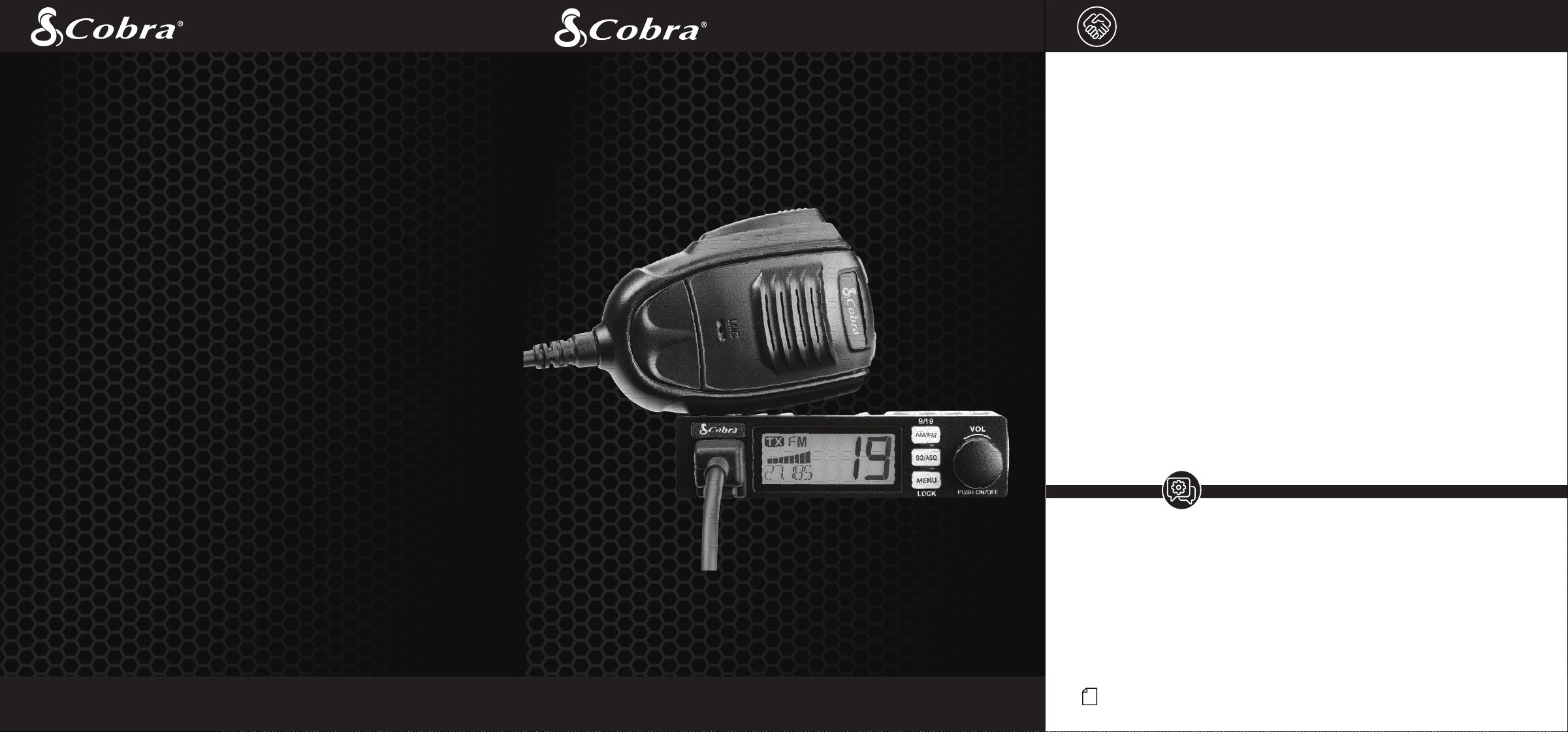
Owners Manual
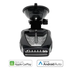
19 MINI AM/FM
Ultra Compact Recreational CB Radio
4W Power / 40 Channels / 12V Adapter
For more information or to order any of our products, please visit our website: www.cobra.com
© 2023 Cobra Electronics Corporation www.cobra.com
Cobra
®
, and the snake design are registered trademarks of Cobra Electronics Corporation, USA.
Cobra Electronics Corporation
™
is a trademark of Cobra Electronics Corporation, USA.
Invented by Al Gross in 1945, the CB radio originally served as a method of communication for troops
during World War II. After the war, Gross worked to make two-way radios a way of communication
for personal use and the CB radio service was established by law in the U.S. in 1949. It wasn’t until
the 1970s that technology advanced and the CB market caught on as a method of communication
between drivers to report police speed traps and road hazards.
The Citizens Band Radio Service consists of 40 channel frequencies that are mostly 10 kHz apart.
Transmitter power is limited to 4 watts in the US, and range can vary depending on the terrain and
quality of the product.
Currently, the Citizens Band service does not require a license for operation, regardless of age, as
long as the rules of operation established by the Federal Communication Commission (FCC) are
followed.
Petition For FCC Part 65 Rule Changes
In 2016, Cobra petitioned the FCC to revise Part 95 rules to allow CB radios to use frequency
modulation (FM). Cobra contended that FM offers improved speech quality and lower noise
interference, which improves the standard of two-way radios and is a benefit to the customer.
Through the direct efforts of Cobra Electronics and the enthusiastic support from loyal customers and
the distribution network, the FCC granted the request and in 2021, Part 95 officially was updated to
include FM as an option for two-way radio use. In addition, AM/FM in CB radios allow backwards
compatibility to communicate with older AM-only CB radios.
Today, thanks to Cobra Electronics’ petitions to improve the quality of the Citizens Band Radio
Service, users can enjoy the benefits of CB radio communication in a range of industries.
Customer Assistance
Should you encounter any problems with this product, not understand its features, menu
or installation, please refer to the this owner's manual. If you require further assistance,
after reading this manual, we are here to help:
For Assistance Outside the U.S.A.
Contact Your Local Dealer
Customer Assistance
Service, Orders & Product Questions
For service, orders, product questions and service hours please call 800-543-1608
or go to www.cobra.com.
Intro Operation Customer
Assistance
Warranty
Notice
Main Icons
Secondary Icons
Caution Warning
Installation
Customer
Assistance
A3
Product Features and
FCC Regulations
A2
Product Features
Intro Operation Customer
Assistance
Warranty
Notice
Main Icons
Secondary Icons
Caution Warning
Installation
Customer
Assistance
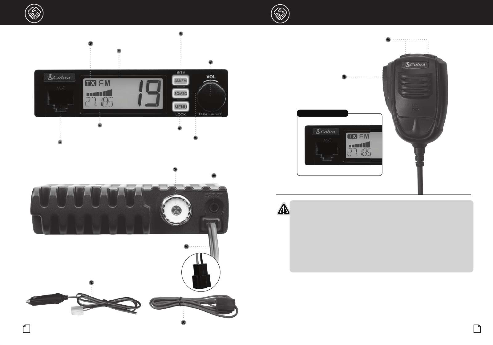
AM/FM
CH 9/19
Power On-Off, Volume
and Channel Control
Squelch/Auto Squelch Control
Antenna Jack
Microphone
Jack
TX Indicator Icon
S/RF
Power Meter
LCD Channel
Display
External
Speaker Jack
12" Power Connection with Connector
FCC Regulations
•
FCC Compliance
Any changes or modifications not expressly approved by Cobra Electronics
could void your authority to operate the equipment.
This device complies with Part 15 of the FCC rules. Operation is subject to
the following two conditions:
(1) This device may not cause harmful interference, and (2) this device
must accept any interference received, including interference that may
cause undesired operation.
Intro Operation Customer
Assistance
Warranty
Notice
Main Icons
Secondary Icons
Caution Warning
Installation
Customer
Assistance
Microphone Connector Detail
Menu/Lock Button
Channel Up/Down
Buttons
Push-To-Talk
(PTT)
48" Hardwire 12V Power Adapter with Connector
48" Stripped and Tinned Hardwire with Connector

Intro Operation Customer
Assistance
Warranty
Notice
Secondary Icons
Caution Warning
Installation
Customer
Assistance
1
Contents
Introduction
Our Thanks, The CB Story and Custmer Assistance........................................................A1
Product Features..........................................................................................................A2
FCC Regulations...........................................................................................................A3
Included in the Package..................................................................................................2
Installation and Start-Up
Powering your 19 MINI AM/FM with the 12V Power Adapter ...........................................3
Powering your 19 MINI AM/FM with the Direct-to-Battery Hardwire Kit............................3
Mounting and Connections
Getting Started - Overview of Main Connectors ..............................................................4
External Speaker...........................................................................................................4
Power...........................................................................................................................4
Fuse .............................................................................................................................4
Microphone Connector ..................................................................................................4
Mounting and Hardwire Installation................................................................................4
CB Antenna Installation..................................................................................................6
Antenna Installation Overview........................................................................................6
Antenna Installation (Permanent)....................................................................................7
Operation
Display .........................................................................................................................8
Turning Your CB ON/OFF ...............................................................................................8
Volume .........................................................................................................................8
AM/FM Mode Selection .................................................................................................9
Channel 9/Channel 19...................................................................................................9
Selecting a Channel.......................................................................................................9
Squelch ........................................................................................................................9
Auto Squelch...............................................................................................................10
Operating Procedure to Receive...................................................................................10
Operationing Procedure to Transmit.............................................................................10
S/RF Power Meter (Signal Strength Meter) ...................................................................11
TX Indicator.................................................................................................................11
Channel Frequency .....................................................................................................11
Enable/Disable VOX.....................................................................................................11
Scan...........................................................................................................................11
Reset to Factory Default ..............................................................................................11
Menu Options..............................................................................................................12
Frequency Ranges.......................................................................................................13
Specifications .............................................................................................................14
Troubleshooting and Replacement Parts ......................................................................15
Warranty
Limited Two-Year Warranty............................................................................................16
Customer Assistance
Need Help? ................................................................................................................17
FCC/IC/RF Exposure....................................................................................................18
2
3
Installation and Start-Up
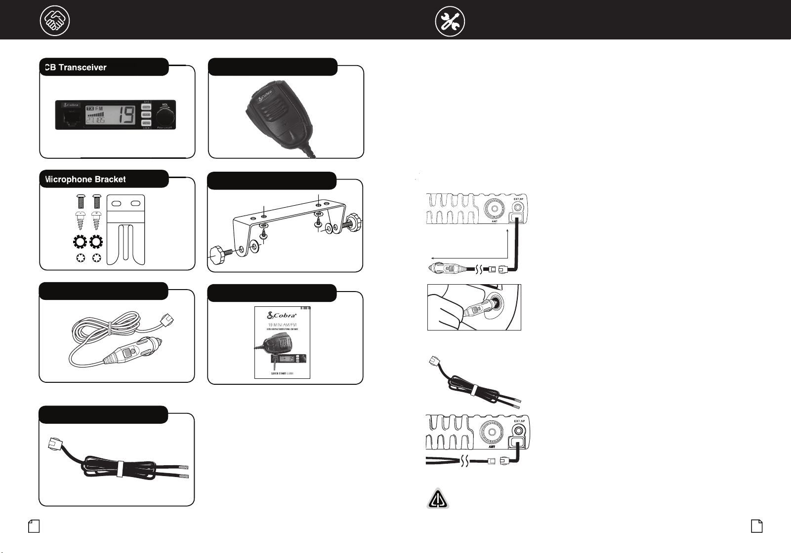
Included in the Package
Secondary Icons
CB Transceiver Microphone
CB Mounting Bracket
Microphone Bracket
Quick Start Guide
Secondar
y Icons
Secondar
y Icons
CB
CB
T
T
ra
ra
n
n
sce
sce
i
i
ve
ve
r
Secondar
r
Secondar
r
Secondar
r
Secondar
M
M
M
M
i
i
i
i
cr
cr
ophon
ophon
ophon
ophon
e
e
Bracke
Bracke
Bracke
Bracke
t
t
t
t
12 Volt Accessory Power Cord
Hardwire Kit
Main Icons
Powering the 19 MINI AM/FM
There are three power options to use and operate the 19 MINI AM/FM CB:
1. From the 12V accessory port in the vehicle,
2. Hardwired directly to the battery, or
3. Hardwired to the fuse box.
Cobra includes a 12V power adapter with the 19 MINI AM/FM CB that allows you to power up quickly and
conveniently. In addition, the 12V power accessory is a modular design to easily connect and disconnect
from the CB. This also allows you to change power from the 12V accessory option to hardwired power as
needed. This design also allows you to use your 19 MINI AM/FM CB in multiple vehicles.
Powering Your 19 MINI AM/FM with the 12V Power Adapter:
1. Select a location to mount the CB using the instructions form
the "Mounting and Hardwire Installation" section of this manual
(page 4).
2. Connect the 12V CLA cord to the CB. Make sure the connection is
secure (shown left).
3. Plug the 12V power adapter into the vehicle’s 12V accessory port
(shown left) the power ON the 19 MINI AM/FM.
Powering Your 19 MINI AM/FM with the Direct-to-Battery Hardwire Kit:
If the 12V power adapter is not preferred to power the CB, or if a
12V port is not not an option in the vehicle, the 19 MINI AM/FM can
be installed direct-to-battery or to the fuse with the hardwire kit
included with the product.
The hardwire kit is a 48" DC power cord and utilizes the same
connector as the 12V adapter accessory to easily connect and
disconnect from the 19 MINI AM/FM.
The hardwire kit provides a 5' connection from the CB directly to the
battery or fuse box, with the same easy-connect modular design.
WARNING: Do not operate the CB without an antenna. This may damage the transmitter.
Total Cord Length: 60” (5’)
Introduction
Our Thanks, The CB Story and Custmer Assistance........................................................A1
Product Features..........................................................................................................A2
FCC Regulations...........................................................................................................A3
Included in the Package..................................................................................................2
Installation and Start-Up
Powering your 19 MINI AM/FM with the 12V Power Adapter ...........................................3
Powering your 19 MINI AM/FM with the Direct-to-Battery Hardwire Kit............................3
Mounting and Connections
Getting Started - Overview of Main Connectors ..............................................................4
External Speaker...........................................................................................................4
Power...........................................................................................................................4
Fuse .............................................................................................................................4
Microphone Connector ..................................................................................................4
Mounting and Hardwire Installation................................................................................4
CB Antenna Installation..................................................................................................6
Antenna Installation Overview........................................................................................6
Antenna Installation (Permanent)....................................................................................7
Operation
Display .........................................................................................................................8
Turning Your CB ON/OFF ...............................................................................................8
Volume .........................................................................................................................8
AM/FM Mode Selection .................................................................................................9
Channel 9/Channel 19...................................................................................................9
Selecting a Channel.......................................................................................................9
Squelch ........................................................................................................................9
Auto Squelch...............................................................................................................10
Operating Procedure to Receive...................................................................................10
Operationing Procedure to Transmit.............................................................................10
S/RF Power Meter (Signal Strength Meter) ...................................................................11
TX Indicator.................................................................................................................11
Channel Frequency .....................................................................................................11
Enable/Disable VOX.....................................................................................................11
Scan...........................................................................................................................11
Reset to Factory Default ..............................................................................................11
Menu Options..............................................................................................................12
Frequency Ranges.......................................................................................................13
Specifications .............................................................................................................14
Troubleshooting and Replacement Parts ......................................................................15
Warranty
Limited Two-Year Warranty............................................................................................16
Customer Assistance
Need Help? ................................................................................................................17
FCC/IC/RF Exposure....................................................................................................18
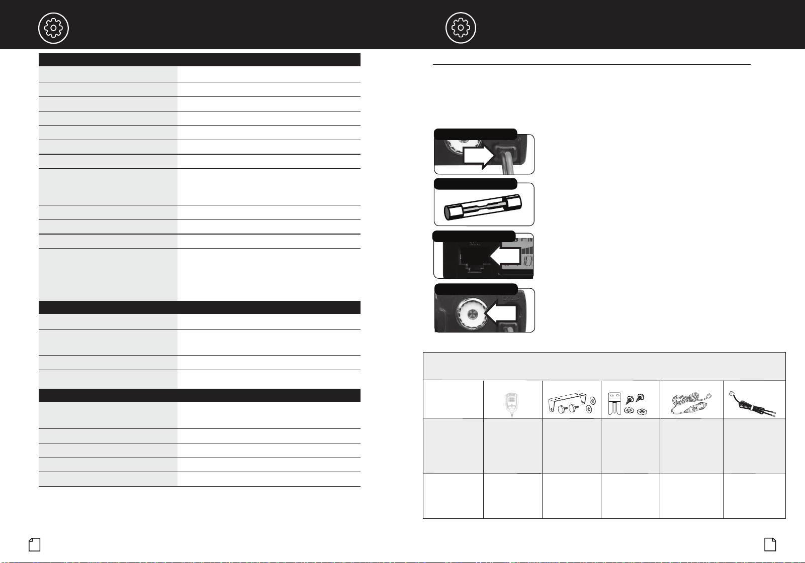
Hardwire Kit Total Cord Length 60” (5’)
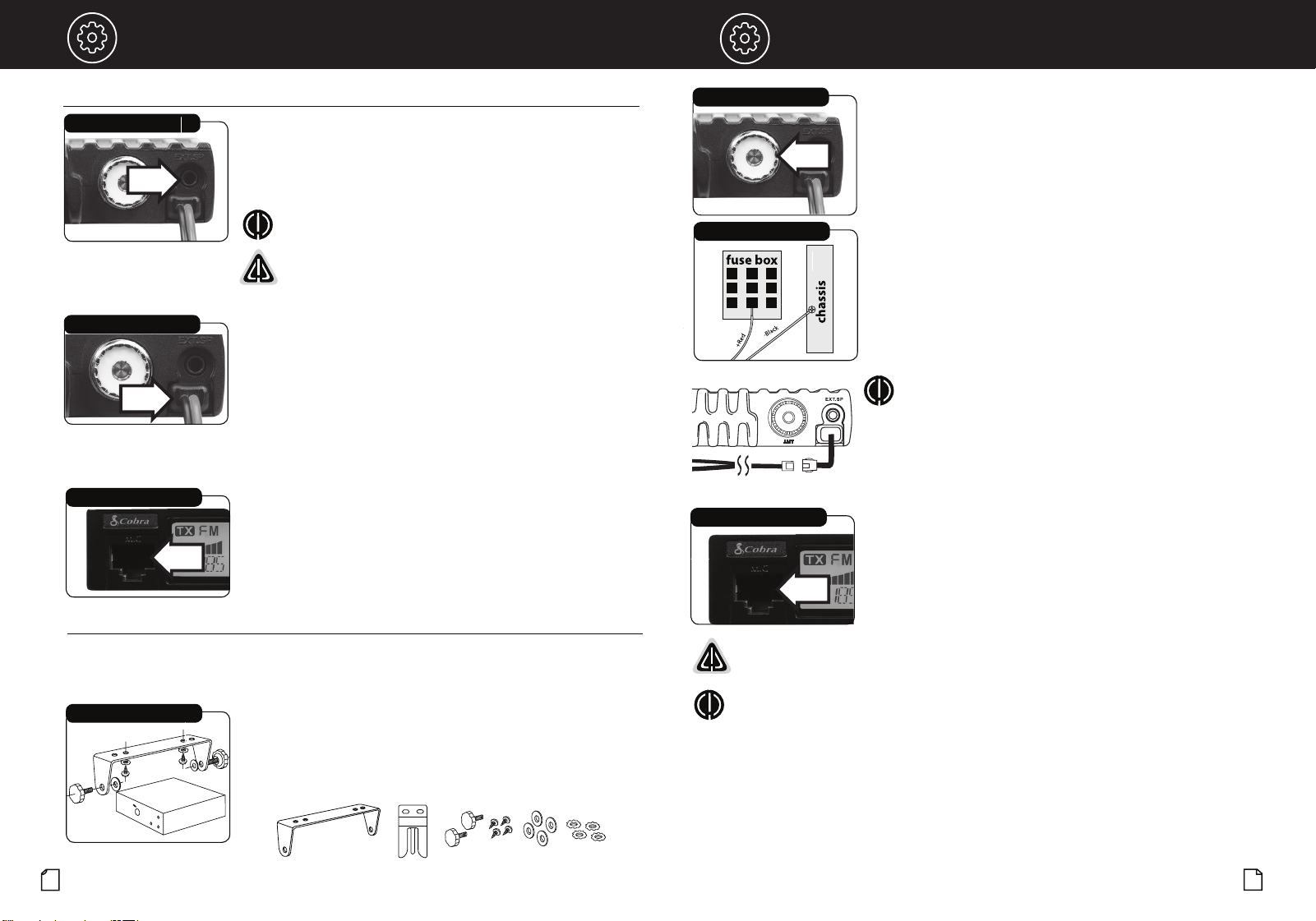
To Mount and Connect Your Transceiver:
1. Hold the radio with mounting bracket in the exact location desired.
Remove the radio and use the mounting bracket as a template to
mark the location for the mounting screws.
2. Drill necessary holes and secure the mounting bracket in location.
3. Connect the antenna cable plug to the receptacle on the back
the unit.
4. Connect the red lead of the DC power cord to an accessory
12 volt fuse.
5. Connect the negative or black lead to the the frame of the vehicle.
NOTE: The battery is bonded to the vehicle frame most
commonly called the "chassis." Sometimes this requires
removing paint to get to a location with good electrical contact.
Installation requirements can vary depending on the vehicle.
6. Connect the CB and hardwire connectors.
7. Mount the microphone bracket in a convenient location that does
not interfere with vehicle operation using the two supplied screws.
8. Connect the microphone plug to the RJ-45 front panel jack.
9. Power the CB ON to use.
WARNING: Do not operate the CB without an antenna. This may damage the transmitter.
NOTE: For improved CB radio performance, connect the radio power leads directly to
the vehicle battery. This helps to ensure:
1. Reduces conducted power line noise into radio by taking advantage of the mechanical filtering
properties of the vehicle battery;
2. By using the correct wire gauge between the battery and radio, voltage drops to the radio
transmitter section are minimized and transmitter RF output power is maximized.
Questions or Need Help? Please call Cobra Customer Care at 800-543-1608.
Intro Operation Customer
Assistance
Warranty
Notice
Main Icons
Secondary Icons
Caution Warning
Installation
Customer
Assistance
5
4
Installation and Start-Up
Intro Operation Customer
Assistance
Warranty
Notice
Main Icons
Secondary Icons
Caution Warning
Installation
Customer
Assistance
Notice
Select a location for the CB radio and microphone bracket that is convenient for operation.
In automobiles, the CB is usually mounted underneath the dash panel, with the microphone bracket
beside it. Avoid areas near airbags and mount to an area that is secure enough to hold it in place.
One (1) universal mounting bracket is supplied along with one (1)
microphone bracket, four (4) self-tapping screws and star washers.
The CB is held in the universal mounting bracket by two (2) thumb
screws, permitting adjustment to the most convenient angle.
CB Radio Bracket
Antenna Connector
Secondary Icons
Fuse Connection
Microphone Connector
Main Icons
Mounting and Hardwire Installation
CB Radio Bracket
Microphone Bracket
Mounting Hardware
Installation and Start-Up
Hardwire Kit Total Cord Length 60” (5’)
Microphone Connector
Allows for convenient removal of the microphone plug
when storage is required. The microphone MUST be
connected to the unit at all times, when in use, for
proper operation.
External Speaker
The speaker jack on the rear panel is used for an External Speaker.
The external speaker should have an 8-Ohm impedance and be rated
to handle at least 4 watts. When the external speaker is plugged
in, the internal speaker is automatically disconnected.
Microphone Connector
External Speaker Jack
Installation
Power Cable
Installation
NOTE: Cobra external speakers are rated at 15 watts.
WARNING: The 19 MINI AM/FM external speaker output is a
Bridge Tied Load (BTL) design. Do not short the speaker wires to
ground as it may damage the speaker amplifier.
Power
Power is supplied to the CB from the main cable located at the back
of the radio. This cable is permanently attached to the radio and
terminates in a connector for a quick installation of the included 12V
vehicle power adapter or to connect to the hardwire kit provided.
Fuse
The DC power wires and the 12V vehicle adapter includes a fuse (in
the tip) of the following type: F2AL 125V - UL rated.
Getting Started - Overview of Main Connectors
•
•
6
7
Installation and Start-Up
Installation and Start-Up
NOTE
: This product requires a CB antenna for use.
Cobra offers a line of CB radio antennas that can be used with your 19 Series CB Radio.
Visit cobra.com for antennas and antenna mounting options..
CB Antenna Installation
Only a properly matched Antenna system will allow maximum power output. In mobile
installations (cars, trucks, boats, etc.), an antenna system that is nondirectional should be used.
When installed in a boat, the transceiver will not operate at maximum efficiency without a ground
plane unless the vessel has a steel hull. Before installing the transceiver in a boat, consult your
dealer for information regarding an adequate grounding system.
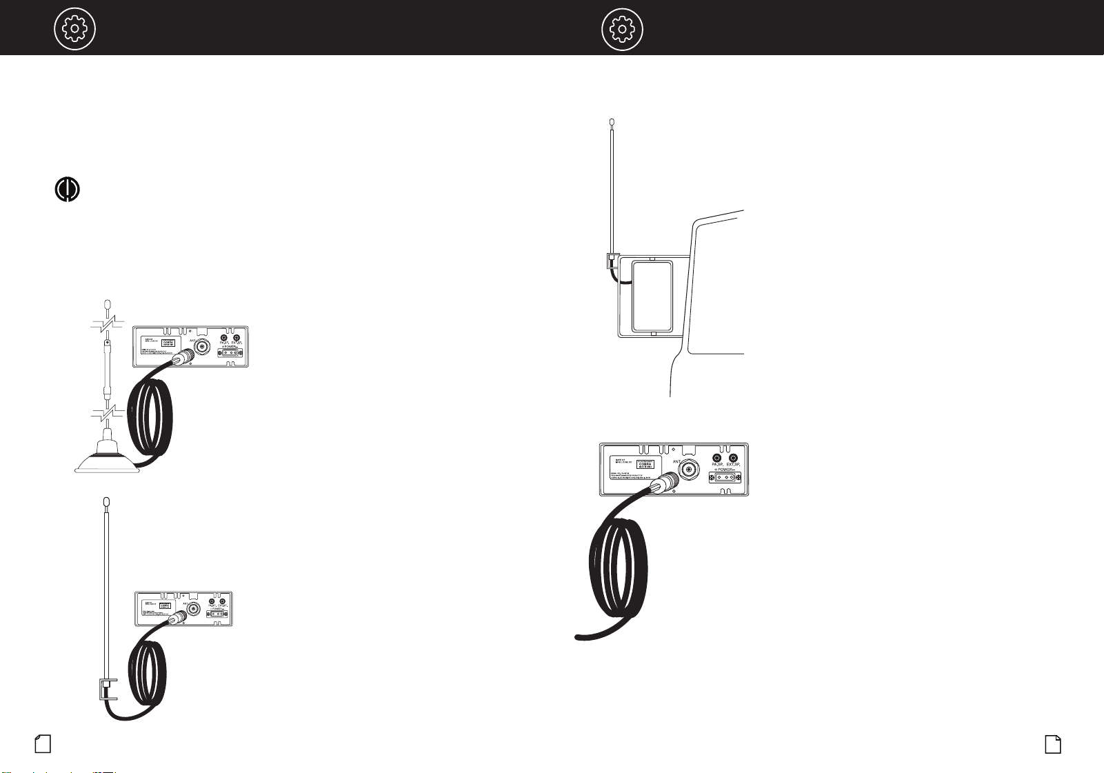
Antenna Installation Overview
A CB radio is only as good as the antenna it is
connected to. You can choose from two types of mobile
CB antennas, either a full-length whip antenna or a
loaded whip antenna. There are several different
mounting options depending your antenna and your
vehicle's specific requirements.
There are two main methods for installing your CB
antenna. Temporary installation or permanent
installation.
1. Temporary installations typically utilize an
antenna with a magnetic base for easy installation
anywhere on the roof or hood of your vehicle. The
Cobra HG A1500 42-inch magnetic mount antenna
is a good example of such an antenna.
2. For permanent installations, the CB antenna is
used in conjunction with a more purpose-built
metal base that attaches to a specific part of a
vehicle, whether that be to the mirror, hood, trunk,
etc.
Antenna Installation (Permanent)
As previously stated, permanent antenna installations
typically use a metal mounting piece in conjunction
with the CB antenna to securely mount to a specific
location on your vehicle. Each vehicle and CB user will
have different mounting requirements, so make sure
to determine the location that best suits your needs
before mounting your antenna.
1. When installing a mobile antenna, it must be fixed
to the vehicle where there is a maximum of metallic
surface (ground plane). A poor ground plane will
result in reduced transmission effectiveness from
your CB radio.
2. For an antenna that is attached by drilling into the
vehicle metallic body, ensure a good electrical
ground between the coax shield and the vehicle
body. Use proper protection for this electrical
connection to guard against exposure to moisture.
3. When mounting of the antenna is complete,
connect your coaxial cable running from your
antenna to the antenna jack on the back of your CB
radio. Be careful not to pinch the cable as this can
also reduce your radio’s transmission effectiveness.
4. Once your antenna is installed and connected to
your CB radio you can adjust its SWR if it is an
adjustable antenna. Consult your owner’s manual
for specific SWR adjustment instructions.
VOL
AM/FM
AM/FM, Channel 9/19 Button
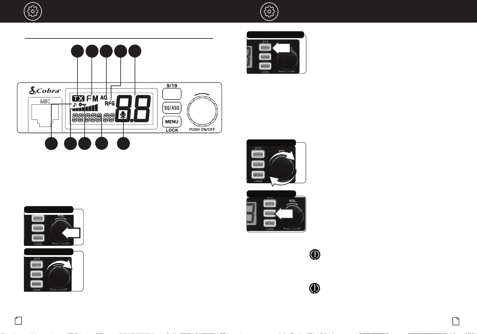
Turning Your CB Radio ON/OFF
The main control of the CB is the channel knob (the largest button
on the radio). Push and release the channel knob to power the CB
radio ON or OFF.
On-Off/Volume Knob
Volume
Rotate the channel knob left or right to adjust the volume.
On-Off/Volume Knob
Notice
A. TX Icon
B. AM or FM Icon
C. Auto Squelch Icon
D. RF Gain Icon
E. Channel
A
B C
E
F
F. Key Tone Icon
G. S/RF Meter
H. Channel Lock Icon
I. Channel Frequency
J. VOX Icon
G
H
I
J
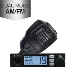
AM/FM Selection
Your 19 Series CB allows you to change transmitter modulation and
communicate over AM or FM modes. Use the AM/FM mode select button to
change modes.
Changing AM/FM modes:
1. Press and release the AM/FM button to choose AM.
2. Press and release the AM/FM button again to choose FM.
Emergency Channel 9/19
Set CH 9 to obtain access to the emergency channel. Set CH 19 to obtain
instant access to the information and calling channel.
Channel 9/19 access:
1. Press and hold the AM/FM button for 2 seconds to select Channel 9.
2. Press and hold the AM/FM button for 2 seconds to select Channel 19.
3. Repeat step 1 to select Channel 9.
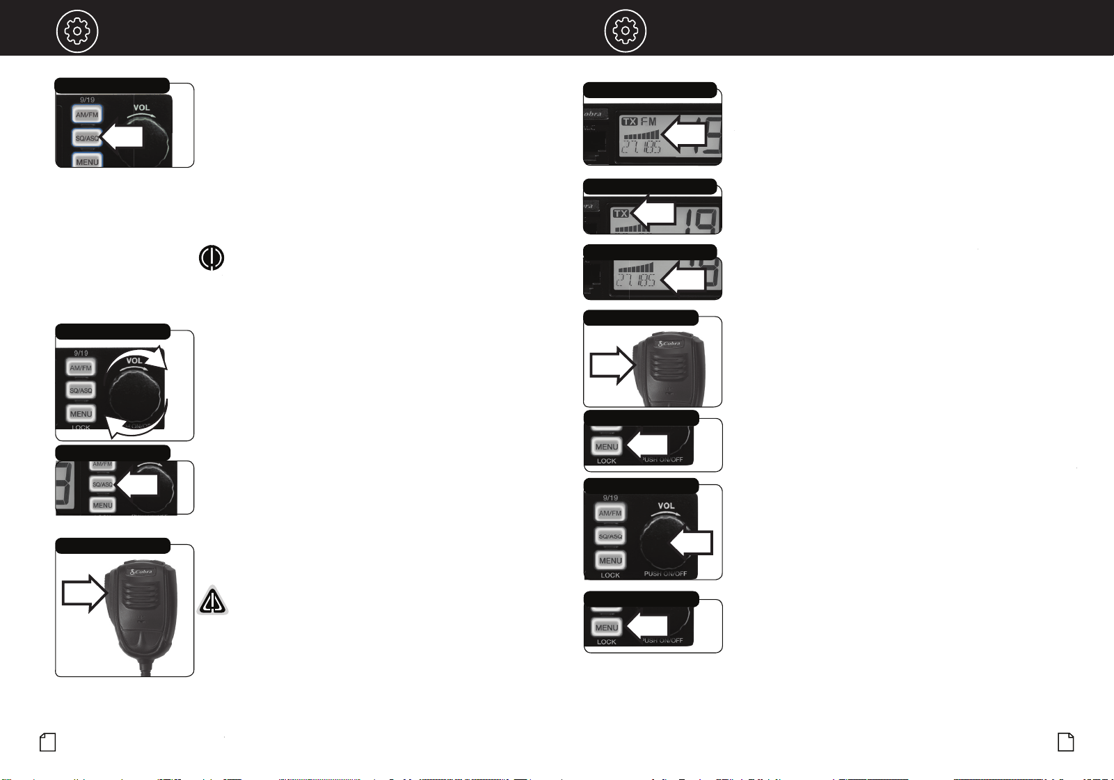
Adjust Squelch
Display
•
Squelch Control (Levels 1 - 34)
Squelch (SQ) is used to cut off or eliminate receiver background noise in
the absence of an incoming signal (when you are not talking).
Operation Operation
8
9
Channel Selection
1. Push and release the Channel knob.
2. Rotate the channel knob left or right to select the channel.
3. Push and release the channel knob to save the setting.
Selecting a Channel
D
To squelch your radio:
1. To adjust the squelch level, press and release the SQ/ASQ button.
SQL -08, 08 indicates the squelch level.
2. Turn the POWER button or press the microphone UP or DN button to
change the squelch level.
NOTE:
using the UP or DN buttons on the microphone changes the
squelch levels rapidly.
3. Press and release the SQ/ASQ button again or wait 5 seconds to store
the selected squelch level and exit.
NOTE:
The higher the number, the stronger an incoming signal needs
to be to break squelch and be received on the CB.
11
10
OperationOperation
Intro Operation Customer
Assistance
Warranty
Notice
Secondary Icons
Caution Warning
Installation
Customer
Assistance
S/RF Power Meter
TX Indicator
Channel Frequency
Adjust Squelch
Auto Squelch Control (Levels 1 - 9)
Auto Squelch (ASQ) continuously measures and blocks the noise of
incoming signals.
Operating Procedure to Receive
Be sure the power cord, antenna and microphone are connected to
the proper connectors before proceeding further (see pages 4 and 5).
To receive:
1. Turn ON the radio.
2. Select the desired channel.
3. Set squelch to OFF (audio noise heard from speaker).
4. Set the receiver volume to a comfortable listen level.
5. Reset the squelch level for the intended listening requirements.
On-Off/Volume Knob
Squelch/ASQ Button
Press-to-Talk Switch
Main Icons
Operating Procedure to Transmit
Be sure the antenna is properly connected to the radio before
transmitting.
WARNING: Prolonged transmitting without an antenna, or
with a poorly matched antenna, could cause damage to the
transmitter.
To transmit:
1. Select the desired channel.
2. The receiver and transmitter are controlled bythe Push-to-Talk
switch on the microphone. Press the switch and the transmitter
is activated; release switch to receive. When transmitting
(on a clear channel), hold the microphone two inches from the
mouth and speak clearly in a normal voice.
Press-to-Talk Switch
To auto squelch your radio:
1. Press and hold the SQ/ASQ key until LCD displays AQ.
AQ -06, 06 indicates the ASQ level. The higher the number, the
stronger an incoming signal needs to be to break squelch and be
received on the CB.
2. Turn the POWER button or press the microphone UP or DN button
to change ASQ level.
NOTE:
Using the UP or DN buttons on the microphone changes the
squelch levels rapidly.
3. Press and release the SQ/ASQ key again or wait 5 seconds to store
the selected ASQ level and exit.
Signal Strength Meter
The Signal Strength Meter indicates the received signal strength
from the antenna. The meter segments shown on the LCD increase
with signal strength.
TX Indicator
The TX Indicator appears when in transmit mode. In this mode,
the meter shows all bars at full output power.
Channel Frequency
Displays the current channel frequency.
Enable/Disable VOX
1. Push and hold the Push-To-Talk switch on the microphone, then
2. Push and release the MENU button.
3. This will both enable and disable the VOX function.
Scan
1.
Press and hold either the Channel UP or DOWN button (about 3
seconds) until SCAN is activated.
2. The radio will automatically scan all 40 Channels and stop on an
active channel. Press any key to end SCAN.
Reset to Factory Default
1. Press and hold the MENU button to enter the menu list.
2. Turn the POWER button or press the microphone UP or DN button to
choose the RESET setting.
3.
Press and release the POWER button to select. RESET will blink in
the display.
4. Press and hold the POWER button until RESET stops blinking.
5. Release the POWER button and the radio will automatically
reset to factory default settings.
VOX
Select from the Menu
Channel Selection
VOX
Select from the Menu
13
12
Intro Operation Customer
Assistance
Warranty
Notice
Main Icons
Secondary Icons
Caution Warning
Installation
Customer
Assistance
Operation
Intro Operation Customer
Assistance
Warranty
Notice
Main Icons
Secondary Icons
Caution Warning
Installation
Customer
Assistance
LCD Display Function Setting
KEY BP Beep on (default): turn on beep
oF: turn off beep
ROG BP
Roger Beep Sound
oF, Tone settings 01 - 06
(End of transmission sound)
oF: (default) turn off
roger beep
VOX L
VOX Level (Sensitivity)
Level: 01 - 09
Default: 03
VOX T VOX Delay Time Level: 01 - 09
Default: 01
RF.GAIN RF Gain Control Levels
: 03, 06, 09 - 48
oF (default) RF gain off
TOTSET Time Out Timer oF, 01 - 10 minutes
Default: 05
PWRAUTO
Automatic Power On
on
(default): Auto power on
oF:
Manual power on
FW VER
Firmware Version
Displays 2-digit
Firmware Version
RESET
See Reset to Factory
Default Section (page 8)
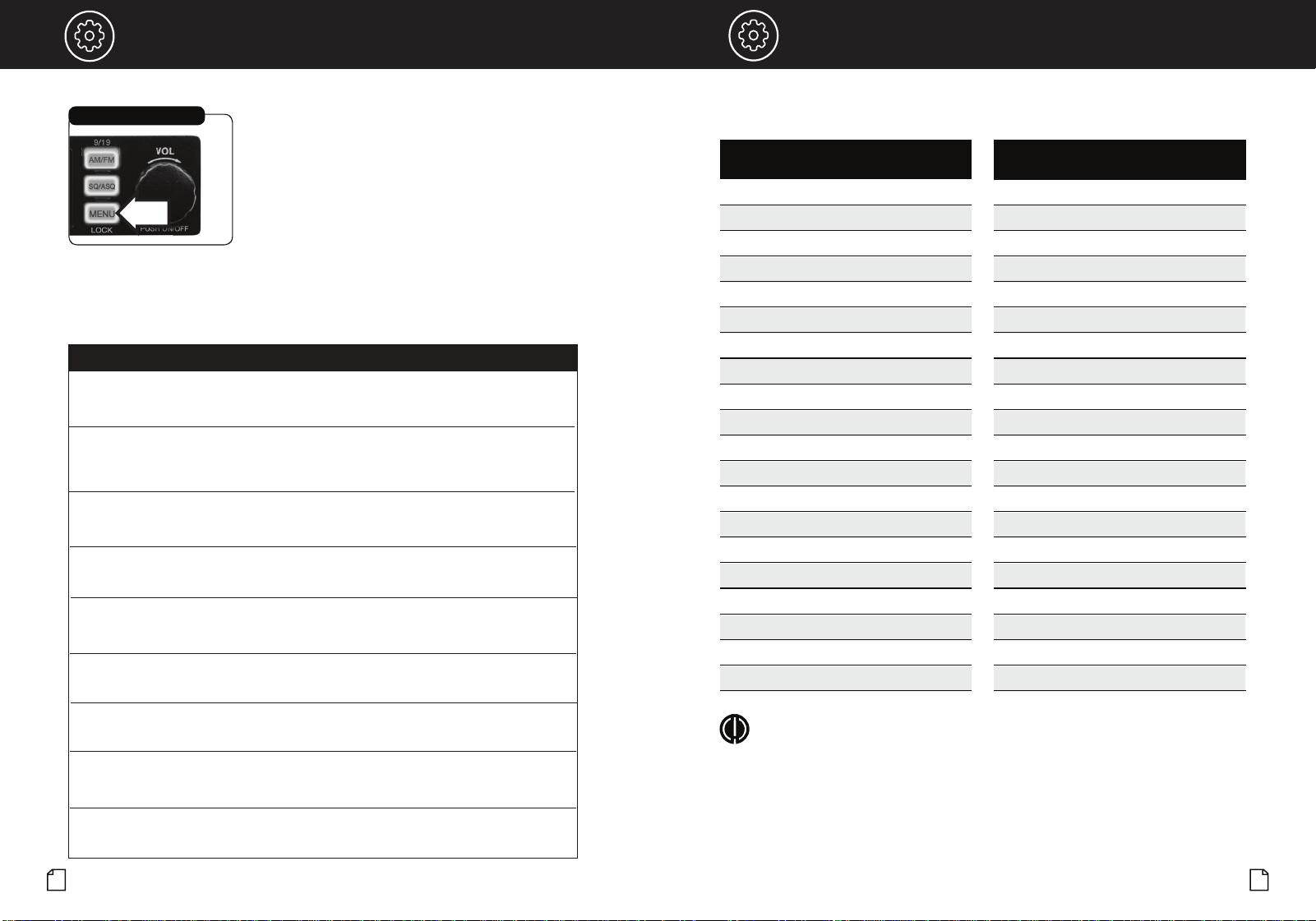
Menu Options
Selecting Options from the Menu
Selecting the Menu
Intro Operation
Intro
Operation
Frequency Ranges
This unit features advanced Phase Lock Loop (PLL) circuitry providing
complete coverage of all 40 CB channels.
NOTE
All 40 channels support AM and FM operating modes.
CB
Channel
Channel Frequency
in MHz
1 26.965
2 26.975
3 26.985
4 27.005
5 27.015
6 27.025
7 27.035
8 27.055
9 27.065
10 27.075
11 27.085
12 27.105
13 27.115
14 27.125
15 27.135
16 27.155
17 27.165
18 27.175
19 27.185
20 27.205
CB
Channel
Channel Frequency
in MHz
21 27.215
22 27.225
23 27.255
24 27.235
25 27.245
26 27.265
27 27.275
28 27.285
29 27.295
30 27.305
31 27.315
32 27.325
33 27.335
34 27.345
35 27.355
36 27.365
37 27.375
38 27.385
39 27.395
40 27.405
Mode
AM/FM
AM/FM
AM/FM
AM/FM
AM/FM
AM/FM
AM/FM
AM/FM
AM/FM
AM/FM
AM/FM
AM/FM
AM/FM
AM/FM
AM/FM
AM/FM
AM/FM
AM/FM
AM/FM
AM/FM
Mode
AM/FM
AM/FM
AM/FM
AM/FM
AM/FM
AM/FM
AM/FM
AM/FM
AM/FM
AM/FM
AM/FM
AM/FM
AM/FM
AM/FM
AM/FM
AM/FM
AM/FM
AM/FM
AM/FM
AM/FM
1. Press and release the MENU button to enter the menu list.
2. Turn the POWER button or press the microphone UP or DN buttons to
choose the desired function.
3.
Press and release the POWER button to enter the setting for the desired
function. Once selected, the setting will blink on the LCD display.
4. Turn the POWER button clockwise or press the microphone UP or DN
buttons to select the desired setting.
5. Press and release the POWER button to confirm the setting and exit.
6. To exit the menu, press and hold the POWER button or press and hold
the microphone PTT switch or wait 10 seconds once the setting
selection has been confirmed.
Signal Strength Meter
The Signal Strength Meter indicates the received signal strength
from the antenna. The meter segments shown on the LCD increase
with signal strength.
TX Indicator
The TX Indicator appears when in transmit mode. In this mode,
the meter shows all bars at full output power.
Channel Frequency
Displays the current channel frequency.
Enable/Disable VOX
1. Push and hold the Push-To-Talk switch on the microphone, then
2. Push and release the MENU button.
3. This will both enable and disable the VOX function.
Scan
1.
Press and hold either the Channel UP or DOWN button (about 3
seconds) until SCAN is activated.
2. The radio will automatically scan all 40 Channels and stop on an
active channel. Press any key to end SCAN.
Reset to Factory Default
1. Press and hold the MENU button to enter the menu list.
2. Turn the POWER button or press the microphone UP or DN button to
choose the RESET setting.
3.
Press and release the POWER button to select. RESET will blink in
the display.
4. Press and hold the POWER button until RESET stops blinking.
5. Release the POWER button and the radio will automatically
reset to factory default settings.
15
14
Intro Operation Customer
Assistance
Warranty
Notice
Main Icons
Secondary Icons
Caution Warning
Installation
Customer
Assistance
Troubleshooting and Replacement Parts
Specifications
•
Check Power Source
Check Fuses in DC Power Cord
1. Check connections to the source of power and make sure it
is the 13.8 VDC required to operate your radio.
2. Check the fuses in the DC power cord and in the 12V accessory
power plug.The main power lead (red) has a 2 Amp fuse -
type F2AL 125V - UL rated in its holder. Use only the above
specified type and size fuse for maximum protection.
Failure to do so will void the warranty.
3. Make certain the microphone is properly
plugged in.
4. Make certain the antenna is properly assembled and connected.
If you are unable to correct the problem, please contact Cobra
customer service.
Maintenance/Adjustment
English
English
Check Microphone Connection
Check Antenna Connection
Notice
y Icons
Caution
Notice
Secondary Icons
Caution
General
Channels CB - 40 CH AM and FM
Frequency Range CB – 26.965 to 27.405 MHZ
Frequency Tolerance 0.005 %
Frequency Control PLL (Phase Lock Loop) Synthesizer
Operating Temperature Range -30° C TO + 65° C
Microphone Plug-in Condenser
Input Voltage 13.8VDC nom. (negative ground)
Current Drain Transmit: AM / FM mod., 1.4A (Maximum)
Receive: Squelched, 0.9 A;
full audio output, 1.2A (nominal)
Size .98"H x 4.37"W x 4.09"D
Weight .66 lbs. (1.37 lbs. in package)
Antenna Connector UHF; SO-239
Fuse DC power cord inline fuse holder contains the
following fuse type: F2AL 125V - UL rated.
12V accessory charging cord contains the following
fuse type: F2AL 125V - UL rated.
Transmitter
Power Output 4 watts
Modulation AM (Amplitude Modulation)
FM (Frequency Modulation)
Frequency Response 300 to 3000 Hz
Output Impedance 50 ohms, unbalanced
Receiver
Sensitivity AM - Less than 1uV for 10dB (S+N)
FM - -120dBm @ 12 dB SINAD)
Selectivity 6 dB @ 7 KHz, 60 dB @ 10KHz
Image Rejection 60 dB, typical
Adjacent-Channel Rejection 50 dB, typical
Automatic Noise Limiter Built-in
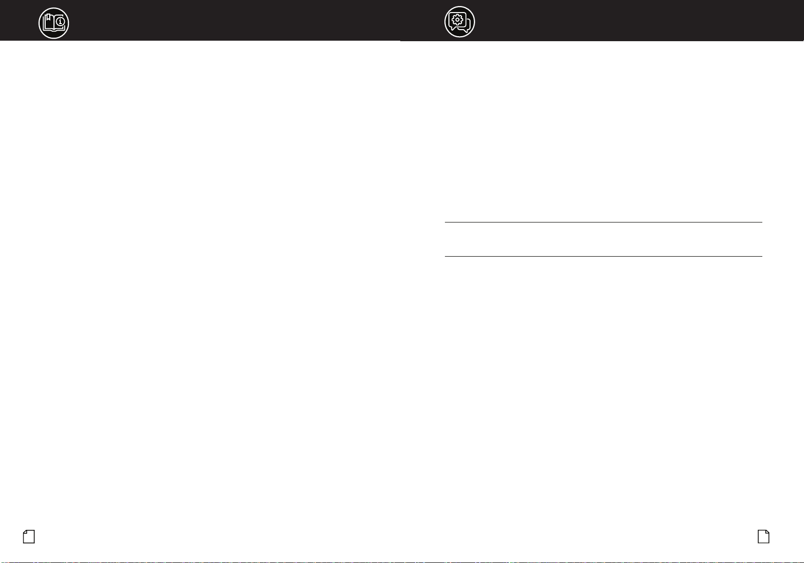
Part/Model # CA-CB19MIC CA-CB19MK CA-CB19BR CCBA19CLA1 CCBA19HWK1
Description:
Contains:
Dynamic
Microphone with
RJ45 Connector
Mounting Kit &
Hardware
Microphone
Mounting Kit
48" 12V power adapter
with connector*
*For use only with
19 MINI AM/FM CB
48" Hardwire with
connector for
direct-to-battery
installation*
*For use only with
19 MINI AM/FM CB
19 MINI CB
Microphone
19 MINI CB Mounting
Bracket
(2) Adjusting Screws
(2) Non-slip Mats
(2) Pads
Microphone Mount
(2) Screws
(2) Pads
12V power adapter
Hardwire with
connector and
stripped/tinned
ends
REPLACEMENT
MICROPHONE
REPLACEMENT CB
MOUNTING KIT
REPLACEMENT
MICROPHONE
MOUNTING KIT
12V POWER
ADAPTER ACCESSORY
12V HARDWIRE
INSTALLATION
WIRING KIT
Go to cobra.com for replacement parts and accessories.
Questions or Need Help? Please call Cobra Customer Care at 800-543-1608.
Your Cobra CB transceiver is specifically designed for the environment encountered in mobile
installations. The use of all solid state circuitry and its light weight result in high reliability. Should a
failure occur, however, review the following, then if necessary, replace parts with identical parts.
Substitution is not recommended. If you have questions, please call Cobra Customer Care at
800-543-1608 (hours are listed on the Cobra.com website).
19 MINI AM/FM Replacement Parts & Accessories
NOTES
Need Help?
17
16
If you have any questions about operation or installing your new Cobra product,
PLEASE CONTACT COBRA FIRST…do not return this product to any retail store.
The contact information for Cobra will vary depending on the country in which you purchased
and utilize the product. For the latest contact information, please go to www.cobra.com/support
For products purchased in the U.S.A. you may call 800-543-1608.
For products purchased in the U.S.A., if your product should require factory service, please
please go to www.cobra.com/support and follow the instructions for returning your product
to the Cobra Factory Service Department for service.
Should there be any problems with this product or further information is needed on its features
please visit www.cobra.com for support, frequently asked questions, Declarations of Conformity,
and full manuals.
For Products Purchased Outside the U.S.A. or Canada
Please contact your local dealer for product service information.
For Products Used in Canada
Industry Canada Notice
This device complies with Industry Canada license-exempt RSS standard(s). Operation is subject
to the following two conditions:
(1) this device may not cause interference, and
(2) this device must accept any interference, including interference that may cause
undesired operation of the device.
Le présent appareil est conforme aux CNR d’Industrie Canada applicables aux appareils radio
excempts de licence. L;exploitation est autorisée aux deux condtions suivantes:
(1) l’appariel ne doit pas produire de brouillage, et
(2) l’utilisateur de l’appareil doit accepter tout brouillage radioélectrique subi, même si le
brouillage est susceptible d’en compromettre le fonctionnement.
•
•
Limited Two-Year Warranty
Warranty Terms:
Cobra warrants your product against all defects in materials and workmanship for a period of two
(2) years from the date of original purchase.
Cobra, at our sole discretion, will repair or replace your product (with the same or comparable
product) free of charge.
Cobra will not pay shipping charges that you incur for sending your product to us. Products
received COD will be refused.
To make a warranty claim, we will require proof or purchase in the form of an invoice or receipt.
No proof of purchase is required for factory direct purchases.
Warranty Exclusions: Warranty does not apply to your product under any of the following
conditions: 1. The serial number has been removed or modified. 2. Your product has been
subjected to misuse or damage (including water damage, physical abuse, and/or improper
installation). 3. Your product has been modified in any way. 4. Your receipt or proof-of-purchase is
from a non-authorized dealer or internet auction site including E-bay, U-bid, or other non-autho-
rized resellers.
LIMITATION OF WARRANTY: EXCEPT AS EXPRESSLY PROVIDED HEREIN, YOU ARE ACQUIRING
THE PRODUCT "AS IS" AND "WHERE IS", WITHOUT REPRESENTATION OR WARRANTY. COBRA
SPECIFICALLY DISCLAIMS ANY REPRESENTATION OR WARRANTY INCLUDING, BUT NOT
LIMITED TO THOSE CONCERNING THE MERCHANTABILITY AND SUITABILITY OF THE PRODUCT
FOR A PARTICULAR PURPOSE. COBRA SHALL NOT BE LIABLE FOR CONSEQUENTIAL, SPECIAL
OR INCIDENTAL DAMAGES INCLUDING, WITHOUT LIMITATION, DAMAGES ARISING OUT OF
THE USE, MISUSE OR MOUNTING OF THE PRODUCT.
The above limitations or exclusions shall be limited to the extent they violate the laws of any
particular state. Cobra is not responsible for products lost in shipment between the owner and our
service center.
General Warranty Information
Each product we manufacture is covered by our factory warranty. While each product may have
unique components and policy, the general guideline below will apply to most Cobra products.
All Cobra products purchased factory-direct or from our Authorized Resellers will come with a full
one to three (1-3) year warranty from the date of the original retail purchase (see policy statement
above for full warranty details and exclusions).
Standard accessories packaged with each model will have a one-year factory warranty.
Accessory items have a one-year factory warranty.
Shipping to our facility is not covered in our warranty. Return shipping is included within the US.
This warranty is non-transferrable.
For the sake of clarity, ‘repair or replace the Product or its defective part’ does not include removal
or installation work, costs or expenses which include but are not limited to labor costs or expenses.
Cobra will not be responsible for lost packages.
19
18
Intro Operation Customer
Assistance
Warranty
Notice
Secondary Icons
Caution Warning
Installation
Customer
Assistance
Intro Operation Customer
Assistance
Warranty
Notice
Main Icons
Secondary Icons
Caution Warning
Installation
Customer
Assistance
FCC Statement FCC Statement
FCC Part 15.19 Warning Statement
THIS DEVICE COMPLIES WITH PART 15 OF THE FCC RULES. OPERATION IS SUBJECT TO THE FOLLOWING TWO
CONDITIONS: (1) THIS DEVICE MAY NOT CAUSE HARMFUL INTERFERENCE, AND (2) THIS DEVICE MUST ACCEPT
ANY INTERFERENCE RECEIVED, INCLUDING INTERFERENCE THAT MAY CAUSE UNDESIRED OPERATION.
FCC Part 15.21 Warning Statement
NOTE: THE GRANTEE IS NOT RESPONSIBLE FOR ANY CHANGES OR MODIFICATIONS NOT EXPRESSLY
APPROVED BY THE PARTY RESPONSIBLE FOR COMPLIANCE. SUCH MODIFICATIONS COULD VOID THE USER’S
AUTHORITY TO OPERATE THE EQUIPMENT.
FCC Part 15.105(b) Warning Statement
NOTE: This equipment has been tested and found to comply with the limits for a Class B digital device, pursuant
to part 15 of the FCC Rules. These limits are designed to provide reasonable protection against harmful
interference in a residential installation. This equipment generates uses and can radiate radio frequency energy
and, if not installed and used in accordance with the instructions, may cause harmful interference to radio
communications. However, there is no guarantee that interference will not occur in a particular installation. If
this equipment does cause harmful interference to radio or television reception, which can be determined by
turning the equipment off and on, the user is encouraged to try to correct the interference by one or more of the
following measures:
- Reorient or relocate the receiving antenna.
- Increase the separation between the equipment and receiver.
- Connect the equipment into an outlet on a circuit different from that to which the receiver is connected.
- Consult the dealer or an experienced radio/TV technician for help.
IC RSS-GEN, Sec 8.4 Warning Statement
ENGLISH: This device complies with Industry Canada license-exempt RSS standard(s). Operation is subject to
the following two conditions: (1) this device may not cause interference, and (2) this device must accept any
interference, including interference that may cause undesired operation of the device.
FRENCH: Le présent appareil est conforme aux CNR d’Industrie Canada applicables aux appareils radio exempts
de licence. L’exploitation est autorisée aux deux conditions suivantes : (1) l’appareil ne doit pas produire de
brouillage, et (2) l’utilisateur de l’appareil doit accepter tout brouillage radioélectrique subi, même si le
brouillage est susceptible d’en compromettre le fonctionnement.
IC RSS-GEN, Sec 8.3 Warning Statement
ENGLISH: This radio transmitter (identify the device by certification number, or model number if Category II) has
been approved by Industry Canada to operate with the antenna types listed below with the maximum
permissible gain and required antenna impedance for each antenna type indicated. Antenna types not included
in this list, having a gain greater than the maximum gain indicated for that type, are strictly prohibited for use
with this device.
Immediately following the above notice, the manufacturer shall provide a list of all antenna types approved for use
with the transmitter, indicating the maximum permissible antenna gain (in dBi) and required impedance for each.
FRENCH:
Le présent émetteur radio (identifier le dispositif par son numéro de certification ou son numéro de
modèle s’il fait partie du matériel de catégorie I) a été approuvé par Industrie Canada pour fonctionner avec les
types d’antenne énumérés ci-dessous et ayant un gain admissible maximal et l’impédance requise pour chaque
type d’antenne. Les types d’antenne non inclus dans cette liste, ou dont le gain est supérieur au gain maximal
indiqué, sont strictement interdits pour l’exploitation de l’émetteur.
RF Exposure Statement
ENGLISH: This equipment complies with FCC radiation exposure limits set forth for an uncontrolled environment.
This equipment should be installed and operated with minimum distance 40cm between the radiator & your
body.
The device is in compliance with RF exposure guidelines, users can obtain Canadian information on RF exposure
and compliance. The minimum distance from body to use the device is 40cm.
FRENCH: Le présent appareil est conforme
Après examen de ce matériel aux conformité ou aux limites d’intensité de champ RF, les utilisateurs peuvent sur
l’exposition aux radiofréquences et compliance d’acquérir les informationscorrespondantes. La distance
minimale du corps à utiliser le dispositif est de 40cm.