WOODWORKING
DUST COLLECTOR
Instruction Manual
IMPORTANT: Your new tool has been engineered and manufactured to WEN’s highest standards for dependability,
ease of operation, and operator safety. When properly cared for, this product will supply you years of rugged,
trouble-free performance. Pay close attention to the rules for safe operation, warnings, and cautions. If you use
your tool properly and for its intended purpose, you will enjoy years of safe, reliable service.
NEED HELP? CONTACT US!
Have product questions? Need technical support? Please feel free to contact us:
TECHSUPPOR[email protected]1-800-232-1195 (M-F 8AM-5PM CST)
For replacement parts and the most up-to-date instruction manuals, visit WENPRODUCTS.COM
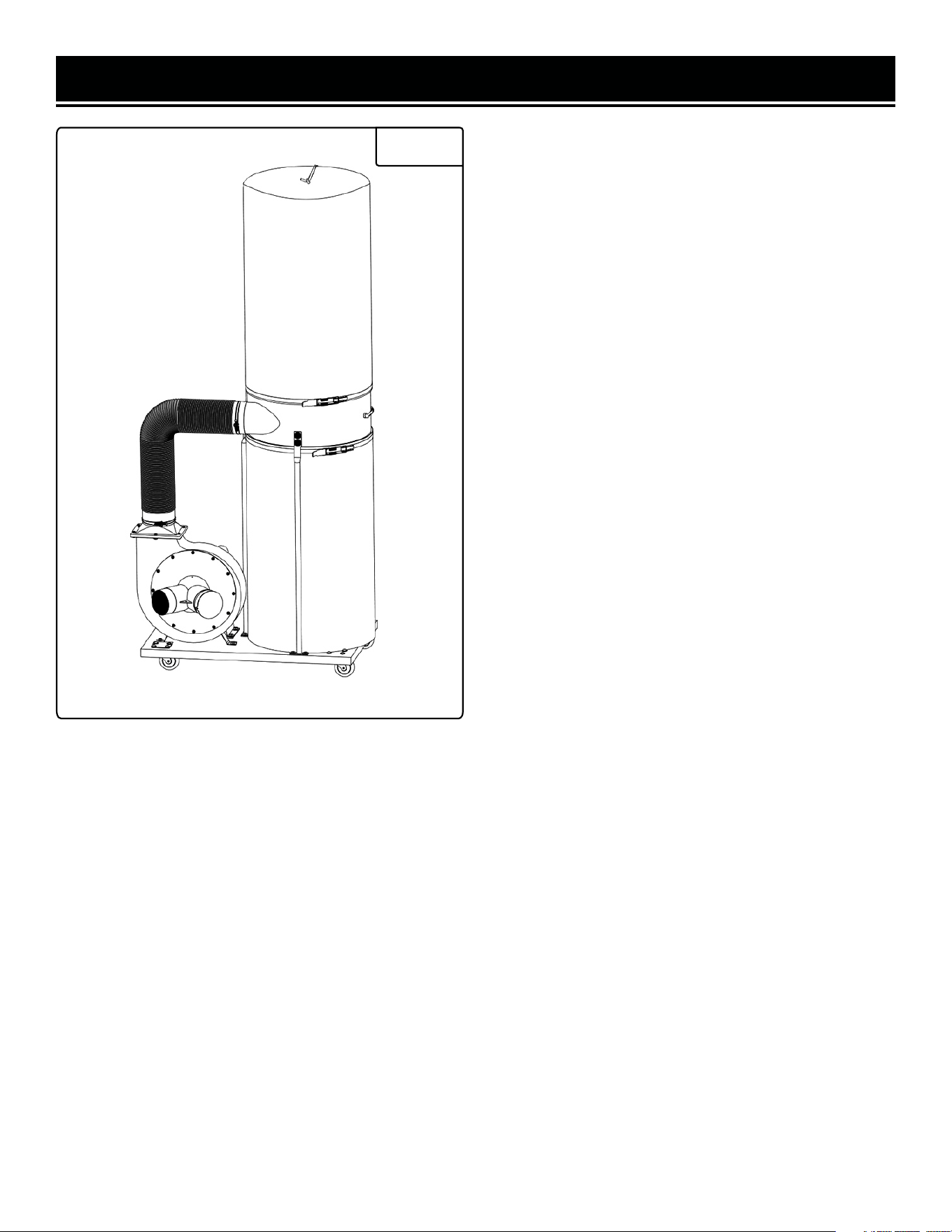
MODEL DC1300

CONTENTS
WELCOME 3
Introduction ..................................................................................................... 3
Specifications ................................................................................................... 3
SAFETY 4
General Safety Rules ........................................................................................ 4
Dust Collector Safety Warnings ....................................................................... 6
Electrical Information ....................................................................................... 7
BEFORE OPERATING 8
Unpacking & Packing List ................................................................................ 8
Assembly & Adjustments ................................................................................. 9
OPERATION & MAINTENANCE 12
Operation ....................................................................................................... 12
Maintenance ....................................................................................................13
Exploded View & Parts List .............................................................................14
Warranty Statement ........................................................................................16
To purchase accessories for your tool, visit WENPRODUCTS.COM
Replacement Collection Bag (Part No. 3403-036)
2

SPECIFICATIONS
INTRODUCTION
Thanks for purchasing the WEN Dust Collector. We know you are excited to put your tool to work, but first, please
take a moment to read through the manual. Safe operation of this tool requires that you read and understand this
operator’s manual and all the labels affixed to the tool. This manual provides information regarding potential safety
concerns, as well as helpful assembly and operating instructions for your tool.
NOTE: The following safety information is not meant to cover all possible conditions and situations that may occur.
WEN reserves the right to change this product and specifications at any time without prior notice.
At WEN, we are continuously improving our products. If you find that your tool does not exactly match this manual,
please visit wenproducts.com for the most up-to-date manual or contact our customer service at 1-800-232-1195.
Keep this manual available to all users during the entire life of the tool and review it frequently to maximize
safety for both yourself and others.
Indicates danger, warning, or caution. The safety symbols and the explanations with them deserve your
careful attention and understanding. Always follow the safety precautions to reduce the risk of fire, electric shock
or personal injury. However, please note that these instructions and warnings are not substitutes for proper ac-
cident prevention measures.
Model number DC1300
Motor 120V, 60 Hz, 14A
Motor Speed 3450 RPM
Impeller Diameter 10 Inches (254mm)
Inlet Hole Diameter 5 Inches
Inlet Y-Adapter Hole Diameter 4 Inches
Air Suction Capacity
1,300 CFM
Collection Bag Capacity
50 Gallons
Filter Bag Rating 5 Microns
Assembled Dimensions 33.5 in. x 22 in. x 73.2 in.
Product Net Weight 86 Pounds
3

GENERAL SAFETY RULES
WORK AREA SAFETY
1. Keep work area clean and well lit. Cluttered or dark
areas invite accidents.
2. Do not operate power tools in explosive atmo-
spheres, such as in the presence of flammable liquids,
gases or dust. Power tools create sparks which may ig-
nite the dust or fumes.
3. Keep children and bystanders away while operating
a power tool. Distractions can cause you to lose control.
ELECTRICAL SAFETY
1. Power tool plugs must match the outlet. Never mod-
ify the plug in any way. Do not use any adapter plugs
with earthed (grounded) power tools. Unmodified plugs
and matching outlets will reduce risk of electric shock.
2. Avoid body contact with earthed or grounded surfac-
es such as pipes, radiators, ranges and refrigerators.
There is an increased risk of electric shock if your body
is earthed or grounded.
3. Do not expose power tools to rain or wet conditions.
Water entering a power tool will increase the risk of elec-
tric shock.
4. Do not abuse the cord. Never use the cord for car-
rying, pulling or unplugging the power tool. Keep cord
away from heat, oil, sharp edges or moving parts.
Damaged or entangled cords increase the risk of electric
shock.
5. When operating a power tool outdoors, use an ex-
tension cord suitable for outdoor use. Use of a cord
suitable for outdoor use reduces the risk of electric
shock.
6. If operating a power tool in a damp location is un-
avoidable, use a ground fault circuit interrupter (GFCI)
protected supply. Use of a GFCI reduces the risk of elec-
tric shock.
PERSONAL SAFETY
1. Stay alert, watch what you are doing and use com-
mon sense when operating a power tool. Do not use a
power tool while you are tired or under the influence
of drugs, alcohol or medication. A moment of inatten-
tion while operating power tools may result in serious
personal injury.
2. Use personal protective equipment. Always wear
eye protection. Protective equipment such as a respira-
tory mask, non-skid safety shoes and hearing protection
used for appropriate conditions will reduce the risk of
personal injury.
3. Prevent unintentional starting. Ensure the switch is
in the off-position before connecting to power source
and/or battery pack, picking up or carrying the tool.
Carrying power tools with your finger on the switch or
energizing power tools that have the switch on invites
accidents.
4. Remove any adjusting key or wrench before turning
the power tool on. A wrench or a key left attached to a
rotating part of the power tool may result in personal
injury.
5. Do not overreach. Keep proper footing and balance
at all times. This enables better control of the power
tool in unexpected situations.
6. Dress properly. Do not wear loose clothing or jew-
elry. Keep your hair and clothing away from moving
parts. Loose clothes, jewelry or long hair can be caught
in moving parts.
Safety is a combination of common sense, staying alert and knowing how your item works. The term “power tool”
in the warnings refers to your mains-operated (corded) power tool or battery-operated (cordless) power tool.
SAVE THESE SAFETY INSTRUCTIONS.
WARNING! Read all safety warnings and all instructions. Failure to follow the warnings and instructions may
result in electric shock, fire and/or serious injury.
4

GENERAL SAFETY RULES
7. If devices are provided for the connection of dust
extraction and collection facilities, ensure these are
connected and properly used. Use of dust collection
can reduce dust-related hazards.
POWER TOOL USE AND CARE
1. Do not force the power tool. Use the correct power
tool for your application. The correct power tool will
do the job better and safer at the rate for which it was
designed.
2. Do not use the power tool if the switch does not turn
it on and off. Any power tool that cannot be controlled
with the switch is dangerous and must be repaired.
3. Disconnect the plug from the power source and/or
the battery pack from the power tool before making
any adjustments, changing accessories, or storing
power tools. Such preventive safety measures reduce
the risk of starting the power tool accidentally.
4. Store idle power tools out of the reach of children
and do not allow persons unfamiliar with the power
tool or these instructions to operate the power tool.
Power tools are dangerous in the hands of untrained us-
ers.
5. Maintain power tools. Check for misalignment or
binding of moving parts, breakage of parts and any
other condition that may affect the power tool’s opera-
tion. If damaged, have the power tool repaired before
use. Many accidents are caused by poorly maintained
power tools.
6. Keep cutting tools sharp and clean. Properly main-
tained cutting tools with sharp cutting edges are less
likely to bind and are easier to control.
7. Use the power tool, accessories and tool bits, etc.
in accordance with these instructions, taking into ac-
count the working conditions and the work to be per-
formed. Use of the power tool for operations different
from those intended could result in a hazardous situa-
tion.
8. Use clamps to secure your workpiece to a stable
surface. Holding a workpiece by hand or using your
body to support it may lead to loss of control.
9. KEEP GUARDS IN PLACE and in working order.
SERVICE
1. Have your power tool serviced by a qualified repair
person using only identical replacement parts. This
will ensure that the safety of the power tool is main-
tained.
CALIFORNIA PROPOSITION 65 WARNING
Some dust created by power sanding, sawing, grinding,
drilling, and other construction activities may contain
chemicals, including lead, known to the State of Califor-
nia to cause cancer, birth defects, or other reproductive
harm. Wash hands after handling. Some examples of
these chemicals are:
• Lead from lead-based paints.
• Crystalline silica from bricks, cement, and other
masonry products.
• Arsenic and chromium from chemically treated
lumber.
Your risk from these exposures varies depending on
how often you do this type of work. To reduce your ex-
posure to these chemicals, work in a well-ventilated area
with approved safety equipment such as dust masks
specially designed to filter out microscopic particles.
Safety is a combination of common sense, staying alert and knowing how your item works. The term “power tool”
in the warnings refers to your mains-operated (corded) power tool or battery-operated (cordless) power tool.
SAVE THESE SAFETY INSTRUCTIONS.
5
WARNING! Read all safety warnings and all instructions. Failure to follow the warnings and instructions may
result in electric shock, fire and/or serious injury.

DUST COLLECTOR SAFETY WARNINGS
DUST COLLECTOR SAFETY
1. This dust collector is intended only for collecting
wood dust and chips from woodworking machines. Do
not use dust collector for anything except wood dust.
Material such as liquids, aerosols, metal dust, screws,
glass, plastic or rock can cause sparks when coming
into contact with any part of the collection system.
2. Never allow steel to come into contact with impeller.
Impact with any hard material may result in sparks which
may cause fire. Be mindful of any situation that results in
a risk of fire.
3. Dust created while using machinery may cause cancer,
birth defects, or long-term respiratory damage. Be aware
of dust hazards associated with each workpiece material
and always wear a NIOSH-approved respirator.
4. Do not place your hands, lumber or tools near the
inlet opening while machine is plugged in or during
operation. Keep animals and children away from open
dust collection inlets.
5. Regularly check and empty the collection bag to avoid
the buildup of fine dust that can increase the risk of fire.
Regularly clean the surrounding area of the machine.
Excessive dust buildup on heat sources such as overhead
lights and electrical panels will increase the risk of fire.
6. Always wear a respirator and safety glasses when
removing, emptying or replacing the collection bag.
Empty dust away from ignition sources and into a
suitable container.
WARNING! Do not let comfort or familiarity with the product replace strict adherence to product safety rules.
Failure to follow the safety instructions may result in serious personal injury.
These safety instructions can’t possibly warn of every scenario that may arise with this tool,
always make sure to stay alert and use common sense during operation.
6
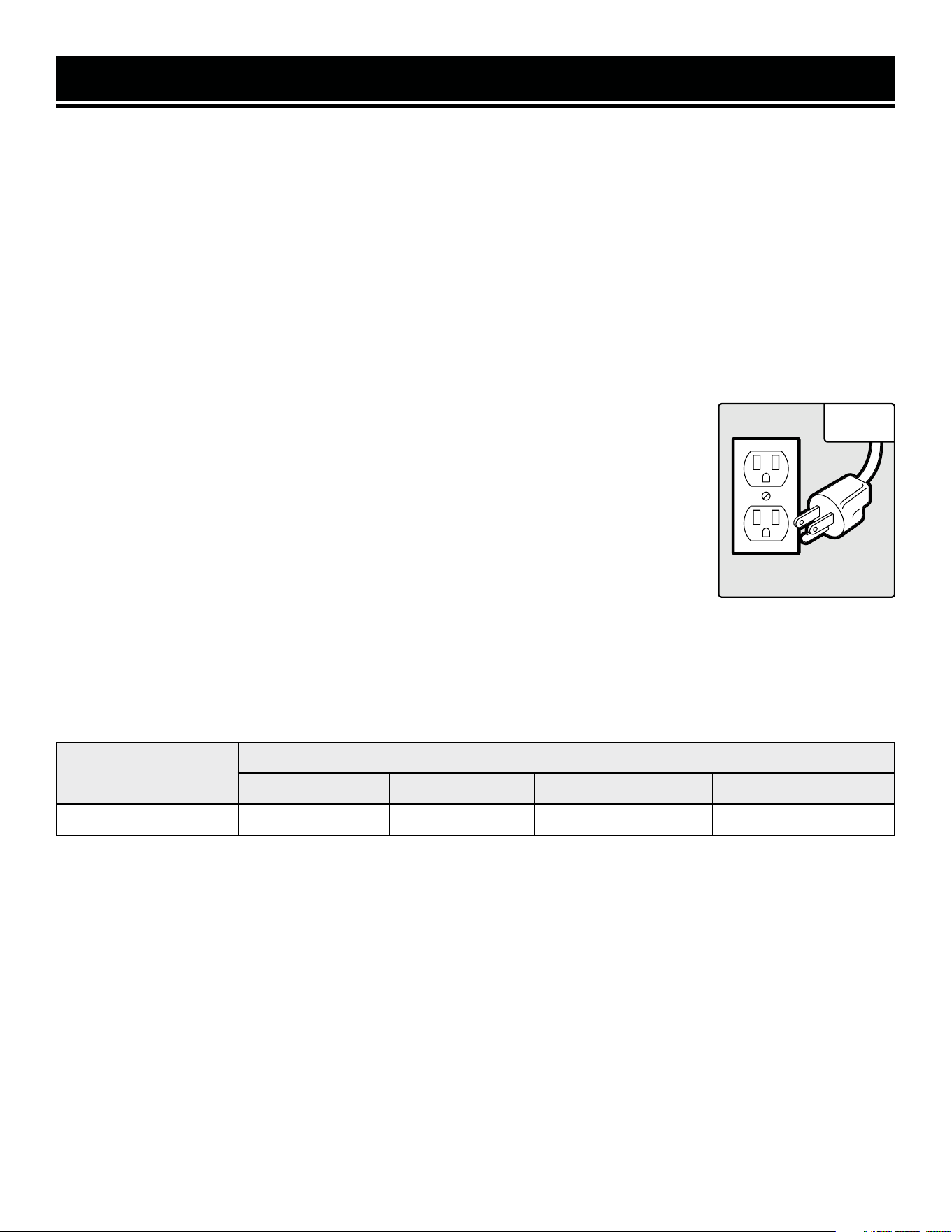
ELECTRICAL INFORMATION
AMPERAGE
REQUIRED GAUGE FOR EXTENSION CORDS
25 ft. 50 ft. 100 ft. 150 ft.
14A 14 gauge 12 gauge Not Recommended Not Recommended
3. Check with a licensed electrician or service personnel if you do not completely under-
stand the grounding instructions or whether the tool is properly grounded.
4. Use only three-wire extension cords that have three-pronged plugs and outlets that
accept the tool’s plug. Repair or replace a damaged or worn cord immediately.
CAUTION! In all cases, make certain the outlet in question is properly grounded. If you
are not sure, have a licensed electrician check the outlet.
GROUNDING INSTRUCTIONS
In the event of a malfunction or breakdown, grounding provides the path of least resistance for an electric current
and reduces the risk of electric shock. This tool is equipped with an electric cord that has an equipment grounding
conductor and a grounding plug. The plug MUST be plugged into a matching outlet that is properly installed and
grounded in accordance with ALL local codes and ordinances.
1. Do not modify the plug provided. If it will not fit the outlet, have the proper outlet installed by a licensed electri-
cian.
2. Improper connection of the equipment grounding conductor can result in electric shock. The conductor with the
green insulation (with or without yellow stripes) is the equipment grounding conductor. If repair or replacement of
the electric cord or plug is necessary, DO NOT connect the equipment grounding conductor to a live terminal.
1. Examine extension cord before use. Make sure your extension cord is properly wired and in good condition.
Always replace a damaged extension cord or have it repaired by a qualified person before using it.
2. Do not abuse extension cord. Do not pull on cord to disconnect from receptacle; always disconnect by pulling on
plug. Disconnect the extension cord from the receptacle before disconnecting the product from the extension cord.
Protect your extension cords from sharp objects, excessive heat and damp/wet areas.
3. Use a separate electrical circuit for your tool. This circuit must not be less than a 12-gauge wire and should
have a 25A fuse or higher. Before connecting the motor to the power line, make sure the switch is in the OFF position
and the electric current is rated the same as the current stamped on the motor nameplate. Running at a lower
voltage will damage the motor.
GUIDELINES AND RECOMMENDATIONS FOR EXTENSION CORDS
When using an extension cord, be sure to use one heavy enough to carry the current your product will draw. An
undersized cord will cause a drop in line voltage resulting in loss of power and overheating. The table below shows
the correct size to be used according to cord length and ampere rating. When in doubt, use a heavier cord. The
smaller the gauge number, the heavier the cord.
Fig. 1
7
UNPACKING
With the help of a friend or trustworthy foe, such as one of your in-laws, carefully remove the dust collector from the
packaging and place it on a sturdy, flat surface. Make sure to take out all contents and accessories. Do not discard
the packaging until everything is removed. Check the packing list below to make sure you have all of the parts and
accessories. If any part is missing or broken, please contact customer service at 1-800-232-1195 (M-F 8-5 CST), or
email [email protected].
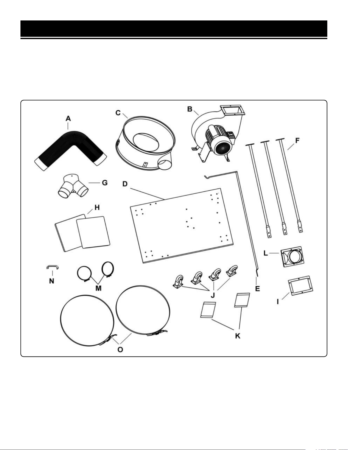
UNPACKING & PACKING LIST
Hose
Motor Assembly
Collector
Base Plate
Upper Support Pole
Lower Support Poles (3)
4-Inch Inlet Adapter
Collection Bag (Clear) & 5-Micron Filter Bag (White)
Outlet Gasket
Swivel Casters (4)
Hardware Bag
Outlet
Hose Clamps (2)
Handle
Bag Clamps (2)
A.
B.
C.
D.
E.
F.
G.
H.
I.
J.
K.
L.
M.
N.
O.
8
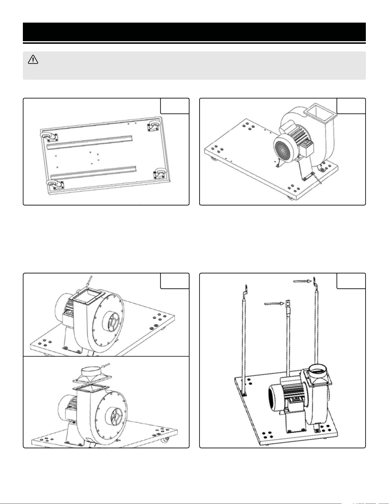
Place the base plate (D) upside down on a flat surface.
Install the 4 casters in the following configuration:
M6x10 Phillips screw, M6 washer, base plate, caster (J)
and M6 nut. Tighten the nuts and make sure all casters
are properly installed and can swivel freely.
Position the outlet gasket (I) on top of the motor assem-
bly and align the holes as shown. Place the outlet (L)
over the gasket and secure it with M6x20 hex screws,
M6 washers and M6 Nuts.
Mount the three lower bag support poles (F) to the base
in the configuration as shown. Secure the poles with
M8x16 hex screws and M8 washers.
Turn the base (D) over and align the motor assembly
(B) with the holes on the base as shown. Secure the
motor assembly using M8x16 hex screws, M8 washers
and M8 nuts.
1. ASSEMBLING THE CASTERS
3. INSTALLING THE OUTLET 4. INSTALLING THE SUPPORT POLES
2. ATTACHING THE MOTOR ASSEMBLY
ASSEMBLY & ADJUSTMENTS
WARNING! Do not attempt to plug in or operate your tool until the entire operator’s manual has been read
and understood. Failure to do so could result in personal injury and damage to the tool.
Fig. 2 Fig. 3
Fig. 4 Fig. 5
9
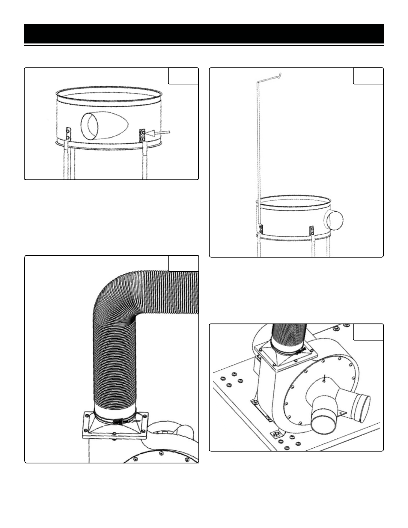
ASSEMBLY & ADJUSTMENTS
Mount the collector (C) onto the two poles in the front
as shown. Make sure that the side port of the collector
is facing the motor assembly to prepare it for hose con-
nection in Step 7. Secure them with M8x16 hex screws
and M8 washers.
5. ASSEMBLING THE COLLECTOR
Fig. 6
The upper bag support pole (E) will be installed in the
position overlapping the third bottom pole as shown.
Secure both poles onto the collector using M8x16 hex
screws and M8 washers.
6. INSTALL THE UPPER SUPPORT POLE
Fig. 7
Attach one end of the hose (A) to the motor assembly
outlet and attach the other end to the collector outlet.
Secure the two ends of the hose with the hose clamps
(M) as shown.
7. CONNECTING THE HOSE
Fig. 8
8. INSTALLING THE INLET CONNECTOR
Fig. 9
Attach the inlet connector (G) onto the inlet port of the
motor assembly. Align the hole on the connector with
the hole on the top of the inlet port and secure using a
cap screw.
10
ASSEMBLY & ADJUSTMENTS
9. INSTALLING THE FILTER BAG
Hang the filter bag (white) onto the hook of the upper bag
support pole. Attach the bag over the top opening of the
collector. Secure it with a bag clamp (O).
10. INSTALLING THE COLLECTION BAG
Attach the plastic collection bag over the bottom open-
ing of the collector around the rubber strip. Bag clips are
located around the collector to assist in holding up the
collection bag. The clips are placed slightly above the legs
so that the bag can be held at the suitable height. Simply
lift the metal plate of the clips and tuck in the bag. Then,
use the second bag clamp (O) to secure the bag all the
way around the collector.
11. INSTALLING THE HANDLE
Install the handle (N) onto the back of the collector using
M8x20 hex screws as shown.
NOTE: When transporting the dust collector, only pull on
the handle. Do not use the support poles for transporta-
tion purposes as they are not designed for pulling and
might come loose.
Your dust collector is now ready to be placed into ser-
vice. Before connecting to a power source, be sure the
power source is properly grounded and is of proper
voltage and amperage (See page 7, Electrical Informa-
tion).
Fig. 10
11

1. Connect the dust collector to your woodworking machine using a 4-inch dust collection hose (not included).
Adaptors may be needed depending the dust port size of your machine.
2. When starting the dust collector, the amperage may spike up to 80 amps for a short moment and this can risk
tripping the electrical circuit. Be sure to both inlet ports are covered before starting your dust collector. The least
amount of power will be drawn when there is no air flow.
3. Making sure the dust collector switch is in the OFF position, insert the power plug into a matching receptacle.
Then, switch ON the dust collector and start operating your woodworking machine.
REPLACING THE COLLECTION BAG
Empty the collection bag on a regular basis. This will allow the dust collector to operate at its maximum efficiency.
Replacement collection bags can be purchased from wenproducts.com by searching the part number 3403-036.
OPERATION
WARNING! To prevent serious injury, make sure all the warnings and instructions have been read and un-
derstood before operating this tool.
WARNING! Wear appropriate respirator or dust mask and safety glasses when operating the dust collector.
Small dust particles can escape from the filter bag, causing them to become airborne and easily inhaled. This
microscopic airborne dust is extremely unhealthy to breathe and can cause health problems.
WARNING! Always wear the appropriate respirator or dust mask and safety glasses when emptying the
collection bags. Small dust particles can escape, causing them to become airborne and easily inhaled. This mi-
croscopic airborne dust is extremely unhealthy to breathe and can cause health problems.
1. Disconnect the dust collector from the power outlet. Make sure you are wearing a respirator or dust mask, and
safety glasses.
2. Release the belt clamp securing the collection bag, then remove the bag from the collector.
3. Securely close the top of the bag and safely dispose of it according to local and federal standards.
4. Install a new collection bag.
12

MAINTENANCE
WARNING! Always ensure that the tool is switched off and the plug is removed from the outlet before mak-
ing any cleaning, adjustments or maintenance procedures. Servicing of the tool must be performed by a quali-
fied technician.
1. Before each use, inspect the general condition of the tool.
Check for:
• Loose hardware,
• Misalignment or binding of moving parts,
• Damaged cord/electrical wiring,
• Cracked or broken parts, and
• Any other condition that may affect its safe operation.
1. Regularly clean dust, chips and other particles from the dust collector. If operation is excessively dusty or dirty,
frequent inspection of motor is required. Vacuum any particles that may have entered the motor.
2. Inspect the dust collector for any damaged or worn parts. Replace any damaged parts immediately for safe and
efficient operation. Frequently check that all nuts, bolts, screws have not loosened due to vibration.
3. Regularly check and empty the collection bag. Always wear respirator and safety glasses when removing, empty-
ing or replacing collection bags. Empty dust away from ignition sources and into an approved container.
4. Store the tool in a clean and dry place away from the reach of children.
PRODUCT DISPOSAL
Used power tools should not be disposed of together with household waste. This product contains electronic com-
ponents that should be recycled. Please take this product to your local recycling facility for responsible disposal and
to minimize its environmental impact.
13
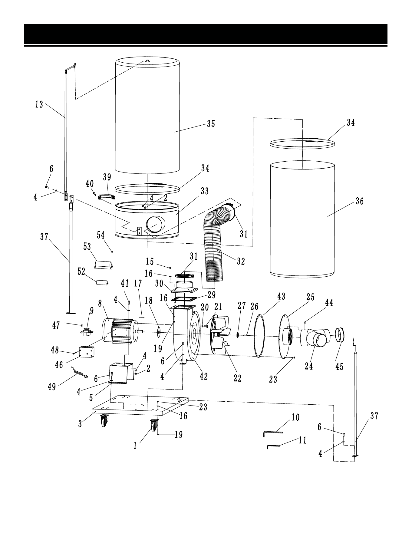
EXPLODED VIEW & PARTS LIST
NOTE: Not all parts may be available for purchase. Parts and accessories that wear down over the course of
normal use are not covered under the warranty.
14

No. Parts No. Description Qty.
1 DC1300-001 Caster 4
2 3403-002 Nut M8 6
3 3403-003 Base Plate 1
4 3403-004 Washer ø8 28
5 3403-005 Motor Base 1
6 3403-006 Hex Screw M8x16 18
8 DC1300-008 Motor 1
9 3403-009 Switch 1
10 3403-010
Hex Wrench M6
(for No. 40)
1
11 3403-011
Hex Wrench M5
(for No. 26)
1
13 3403-013 Upper Bag Support 1
15 3403-015 Hex Screw M6x20 6
16 3403-016 Washer ø6 28
17 3403-017 Key A5x25 1
18 3403-018 Packing 1
19 3403-019 Nut M6 22
20 3403-020 Spring Washer ø10 4
21 3403-021 Hex Screw M10x16 4
22 DC1300-022 Turbo Fan 1
23 3403-023 Screw M6x10 28
24 3403-024 Inlet 1
25 3403-025 Inlet Cover 1
26 3403-026
Hex Screw M6x20
(left)
1
No. Parts No. Description Qty.
27 3403-027 Washer 1
29 3403-029 Outlet Gasket 1
30 3403-030 Outlet 1
31 3403-031 Hose Clamp 2
32 3403-032 Hose ø125x75mm 1
33 3403-033 Collector 1
34 DC1300-034 Bag Clamp 2
35 3403-035 Filter Bag 1
36 3403-036 Collector Bag 1
37 3403-037 Collector Support 3
39 3403-039 Handle 1
40 3403-040 Hex Screw M8x20 2
41 3403-041 Hex Screw M8x25 4
42 3403-042 Fan Housing 1
43 3403-043 Packing 1
44 3403-044 Cap Screw 1
45 3403-045 Cover 1
46 DC1300-046 Switch Box 1
47 3403-047 Screw ST4.2x13 2
48 3403-048 Screw ST4x60 4
49 DC1300-049 Plug and Cord 1
52 3403-052
Capacitor 2 (Blue)
(400uf/125V)
1
53 3403-053 Capacitor Cover 1
54 3403-054 Screw 2
EXPLODED VIEW & PARTS LIST
NOTE: Not all parts may be available for purchase. Parts and accessories that wear down over the course of
normal use are not covered under the warranty.
15

WARRANTY STATEMENT
WEN Products is committed to building tools that are dependable for years. Our warranties are consistent with this
commitment and our dedication to qualit
y.
LIMITED WARRANTY OF WEN PRODUCTS FOR HOME USE
GRE
AT LAKES TECHNOLOGIES, LLC (“Seller”) warrants to the original purchaser only, that all WEN
consumer
power tools will be free from defects in material or workmanship during personal use for a period of two (2) years
used
for professional or commercial use. Purchaser has 30 days from the date of purchase to report missing or
damaged parts.
SELLER’S
SOLE OBLIGATION AND YOUR EXCLUSIVE REMEDY under this Limited Warranty and, to the extent per-
mitted
by law, any warranty or condition implied by law, shall be the replacement of parts, without charge, which a
re
defective
in material or workmanship and which have not been subjected to misuse, alteration, careless handling,
misrepai
r, abuse, neglect, normal wear and tear,
improper maintenance, or other conditions adversely affecting the
Product
or the component of the Product, whether by accident or intentionally, by persons other than Seller. To
make
a claim under this Limited Warranty, you must make sure to keep a copy of your proof of purchase that
clearly
-
dor
of Great Lakes Technologies, LLC. Purchasing through third party vendors, including but not limited to garage
sales,
pawn shops, resale shops, or any other secondhand merchant, voids the warranty included with this
product.
Contact [email protected] or 1-800-232-1195 with the following information to make arrangements:
your
shipping address, phone number, serial number, required part numbers, and proof of purchase. Damaged
or
defective parts and products may need to be sent to WEN before the replacements can be shipped out.
-
turning
a product for warranty service, the shipping charges must be prepaid by the purchaser. The product
must
be
shipped in its original container (or an equivalent), properly packed to withstand the hazards of shipment. The
product
must be fully insured with a copy of the proof of purchase enclosed. There must also be a description of
the
will be returned and shipped back to the pur
chaser at no charge for addresses within the contiguous United States.
THIS
LIMITED WARRANTY DOES NOT APPLY TO ITEMS THAT WEAR OUT FROM REGULAR USAGE OVER TIME,
INCLUDING
BELTS, BRUSHES, BLADES, BATTERIES, ETC. ANY IMPLIED WARRANTIES SHALL BE LIMITED IN
DUR
ATION TO TWO (2) YEARS FROM DATE OF PURCHASE. SOME STATES IN THE U.S. AND SOME CANADIAN
PROVINCES
DO NOT ALLOW LIMITATIONS ON HOW LONG AN IMPLIED WARRANTY LASTS, SO THE ABOVE LIMI-
TAT
ION MAY NOT APPLY TO YOU.
IN
NO EVENT SHALL SELLER BE LIABLE FOR ANY INCIDENTAL OR CONSEQUENTIAL DAMAGES (INCLUDING
BUT
NOT LIMITED TO LIABILITY FOR LOSS OF PROFITS) ARISING FROM THE SALE OR USE OF THIS PRODUCT.
SOME ST
ATES IN THE U.S. AND SOME CANADIAN PROVINCES DO NOT ALLOW THE EXCLUSION OR LIMITAT
ION
OF
INCIDENTAL OR CONSEQUENTIAL DAMAGES, SO THE ABOVE LIMITATION OR EXCLUSION MAY NOT APPLY
TO YOU.
THIS
LIMITED WARRANTY GIVES YOU SPECIFIC LEGAL RIGHTS, AND YOU MAY ALSO HAVE OTHER RIGHTS
WHICH
VARY FROM STATE TO STATE IN THE U.S., PROVINCE TO PROVINCE IN CANADA AND FROM COUNTRY
TO COUNT
RY.
THIS
LIMITED WARRANTY APPLIES ONLY TO ITEMS SOLD WITHIN THE UNITED STATES OF AMERICA, CANA-
DA
AND THE COMMONWEALTH OF PUERTO RICO. FOR WARRANTY COVERAGE WITHIN OTHER
COUNTRIES,
CONT
ACT THE WEN CUSTOMER SUPPORT LINE. FOR WARRANTY PARTS OR PRODUCTS REPAIRED UNDER
W
ARRANTY SHIPPING TO ADDRESSES OUTSIDE OF THE CONTIGUOUS UNITED STATES, ADDITIONAL
SHIPPING
CHARGES MAY APPLY.
V. 2022.01.25
16