
Originally written in UK English Date Published: 01 / 11 / 2018
Original Instructions
Originalbetriebsanleitung
Notice Originale
Instrucciones Originales
Instructions Originales
Oryginalna Instrukcja
Originele Instructies
Ursprungliga instruktioner
Instrucțiuni Iniţiale
026-0001, 026-0002,
026-0003, 026-0004
027-0001, 027-0002,
027-0003, 027-0004C,
027-0001C, 027-0002C,
027-0003C, 027-0006,
027-0010
027-0001A, 027-0002A,
027-0003A, 027-0004A,
027-0006A
GB2438285

2
www.evolutionpowertools.com
(1.2) INTRODUCTION
IMPORTANT
Please read these operating and safety instructions
carefully and completely.
For your own safety, if you are uncertain about any
aspect of using this equipment please access the relevant
Technical Helpline, the number of which can be found on
the Evolution Power Tools website. We operate several
Helplines throughout our worldwide organization, but
Technical help is also available from your supplier.
(1.3) CONTACT:
Web: www.evolutionpowertools.com
UK/EU/AUS: customer[email protected]
USA: evolutioninfo@evolutionpowertools.com
(1.4) WARRANTY
Congratulations on your purchase of an Evolution Power
Tools Machine. Please complete your product registration
‘online’ as explained in the registration leaflet included
with this machine. This will enable you to validate your
machine’s warranty period via Evolutions website by
entering your details and thus ensure prompt service if
ever needed.
We sincerely thank you for selecting
a product from Evolution Power Tools.
3
www.evolutionpowertools.com
EN
USA
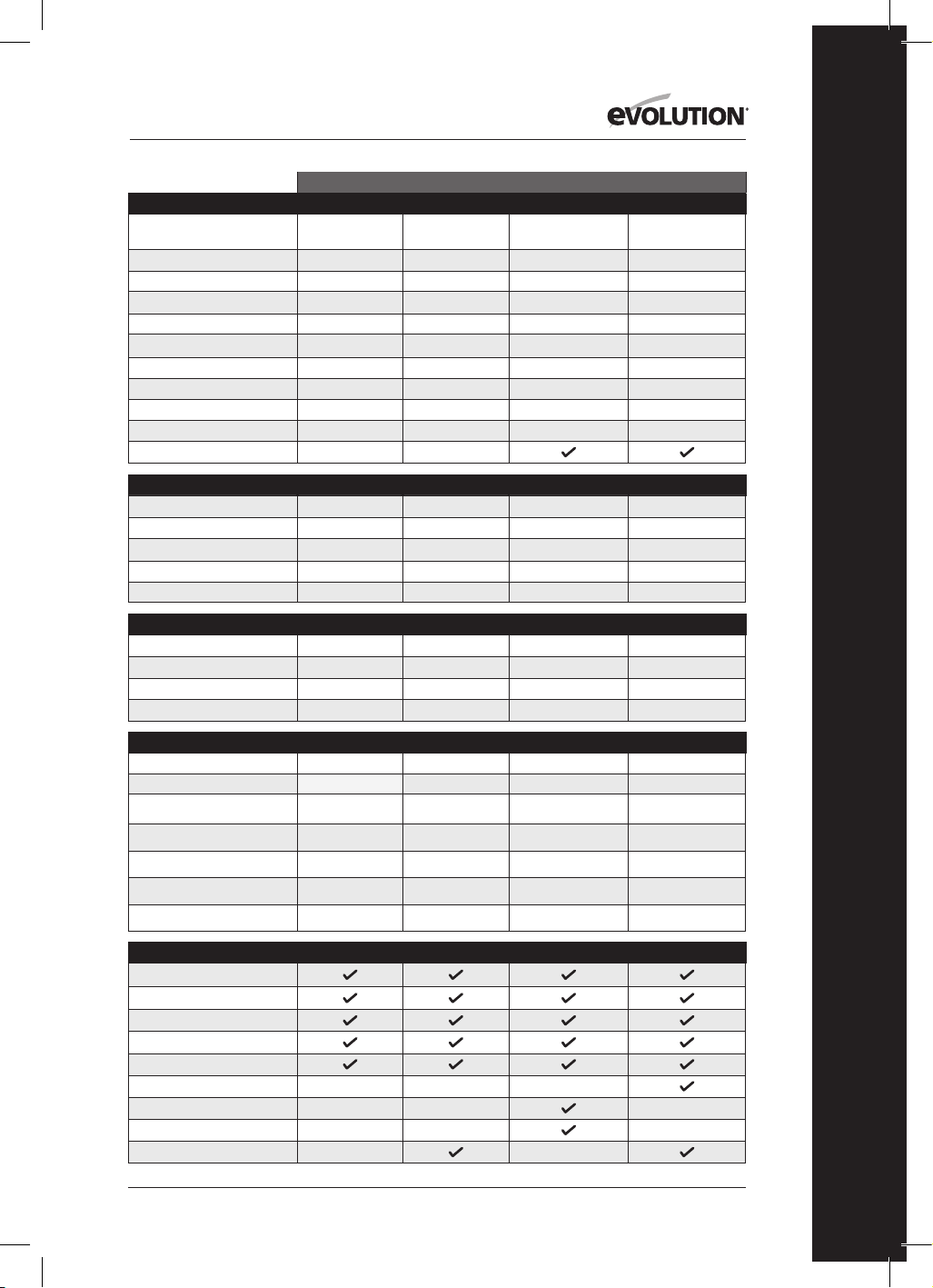
MACHINE SPECIFICATIONS R165CCSL R185CCS R185CCSX R185CCSX+
Model No: 026-0004 027-0004 027-0004C 027-0004A
Motor EU (220-240V ~ 50 Hz)
Motor UK (110V ~ 50 Hz)
Motor USA (120V ~ 60 Hz) 10A 15A 15A 15A
No-Load Speed (220-240v)
No-Load Speed (110v & 120v) 3900 min
-1
/ rpm 3700 min
-1
/ rpm 3700 min
-1
/ rpm 3700 min
-1
/ rpm
Weight 9.5 lb 10.8 lb 11.2 lb 11.2 lb
Max. Blade Bevel Angle (Degrees) 45˚ 60˚ 45˚ 45˚
Power Cable Length 10 ft 13 ft 13 ft 13 ft
Circular Saw Base Type Pressed Steel Cast Aluminum Cast Aluminum Cast Aluminum
Cutting Track Compatible
CUTTING CAPACITIES R165CCSL R185CCS R185CCSX R185CCSX+
Mild Steel Plate (Max. Thickness) 1/8" 1/4” 1/4” 1/4”
Mild Steel Box Section (Max. Wall) 1/8” 1/4” 1/4” 1/4”
Max. Cutting Thickness (0°) 2-3/32" 2-1/2”
2-1/2” (2-5/16” w/Track) 2-1/2” (2-5/16” w/Track)
Max. Cutting Thickness (45°) 1-11/32" 1-9/16”
1-13/16” (1-5/8” w/Track) 1-13/16” (1-5/8” w/Track)
Max. Cutting Thickness (60°) 1”
BLADE SPECIFICATIONS R165CCSL R185CCS R185CCSX R185CCSX+
Blade Diameter Ø 6-1/2" Ø 7-1/4” Ø 7-1/4” Ø 7-1/4”
Number of Teeth 14 20 16 20
Bore Diameter 25/32" 25/32” 25/32” 25/32”
Kerf 1.7mm 1.7mm 1.7mm 1.7mm
NOISE & VIBRATION DATA R165CCSL R185CCS R185CCSX R185CCSX+
Sound Pressure Level L
pa
92,4dB(A) K:3dB(A)
97,3dB(A) K=3 dB(A) 97,3dB(A) K=3 dB(A) 97,3dB(A) K=3 dB(A)
Sound Power Level L
wa
103,4dB(A) K:3dB(A)
105,3dB(A) K=3 dB(A) 105,3dB(A) K=3 dB(A) 105,3dB(A) K=3 dB(A)
Vibration - Main Handle (Sawing Wood)
a
h,w
= 2,747m/s
2
A
h,w
= 3,347m/s
2
a
h,w
= 3,347m/s
2
a
h,w
= 3,347m/s
2
Vibration - Auxiliary Handle (Sawing Wood)
a
h,w
= 2,619m/s
2
A
h,w
= 3,119m/s
2
a
h,w
= 3,119m/s
2
a
h,w
= 3,119m/s
2
Vibration - Main Handle (Sawing Metal)
a
h,M
= 2,302m/s
2
a
h,M
= 3,572m/s
2
a
h,M
= 3,572m/s
2
a
h,M
= 3,572m/s
2
Vibration - Auxiliary Handle (Sawing Metal)
a
h,M
= 2,239m/s
2
a
h,M
= 3,241m/s
2
a
h,M
= 3,241m/s
2
a
h,M
= 3,241m/s
2
Uncertainty K
1,5m/s
2
1,5m/s
2
1,5m/s
2
1,5m/s
2
ITEMS SUPPLIED R165CCSL R185CCS R185CCSX R185CCSX+
Multi-Material TCT Blade
Hex Key (Blade Change)
Parallel Edge Guide
Dust Port Adapter
Dust Hose Connector
Carry Case
Cutting Track - 340mm (13-3/8”) x3
Connector Bar & Screws (x4)
LED Light
SPECIFICATIONS

4
www.evolutionpowertools.com
UK / EU / AUS
R165CCSL R185CCS R185CCSX R185CCSX+
026-0001 / 026-0002 /
026-0003
027-0001C /
027-0002C / 027-0003C
027-0001 /
027-0002 / 027-0003
027-0001A /
027-0002A / 027-0003A
1200W 1600W 1600W 1600W
1200W 1600W 1600W 1600W
3700 min
-1
/ rpm 3900 min
-1
/ rpm 3900 min
-1
/ rpm 3900 min
-1
/ rpm
3700 min
-1
/ rpm 3700 min
-1
/ rpm 3700 min
-1
/ rpm 3700 min
-1
/ rpm
4.3 kg 4.9 kg 5.1 kg 5.1 kg
45˚ 60˚ 45˚ 45˚
3m 3m 3m 4m
Pressed Steel Cast Aluminium Cast Aluminium Cast Aluminium
R165CCSL R185CCS R185CCSX R185CCSX+
3mm 6mm 3mm 6mm
3mm 6mm 3mm 6mm
53mm 64mm 64mm (59mm w/Track) 64mm (59mm w/Track)
34mm 40mm 47mm (42mm w/Track) 47mm (42mm w/Track)
24mm
R165CCSL R185CCS R185CCSX R185CCSX+
Ø 165mm Ø 185mm Ø 185mm Ø 185mm
14 20 16 20
20mm 20mm 20mm 20mm
1.7mm 1.7mm 1.7mm 1.7mm
R165CCSL R185CCS R185CCSX R185CCSX+
92,4dB(A) K:3dB(A) 97,3dB(A) K=3 dB(A) 97,3dB(A) K=3 dB(A) 97,3dB(A) K=3 dB(A)
103,4dB(A) K:3dB(A) 105,3dB(A) K=3 dB(A) 105,3dB(A) K=3 dB(A) 105,3dB(A) K=3 dB(A)
a
h,w
= 2,747m/s
2
a
h,w
= 3,347m/s
2
a
h,w
= 3,347m/s
2
a
h,w
= 3,347m/s
2
a
h,w
= 2,619m/s
2
a
h,w
= 3,119m/s
2
a
h,w
= 3,119m/s
2
a
h,w
= 3,119m/s
2
a
h,M
= 2,302m/s
2
a
h,M
= 3,572m/s
2
a
h,M
= 3,572m/s
2
a
h,M
= 3,572m/s
2
a
h,M
= 2,239m/s
2
a
h,M
= 3,241m/s
2
a
h,M
= 3,241m/s
2
a
h,M
= 3,241m/s
2
1,5m/s
2
1,5m/s
2
1,5m/s
2
1,5m/s
2
R165CCSL R185CCS R185CCSX R185CCSX+
5
www.evolutionpowertools.com
EN
VIBRATION
(1.5) Note: The vibration measurement
was made under standard conditions in
accordance with: EN 62841-1: 2015,
EN 62841-2-5: 2014
Warning: Wear hearing protection!
The declared vibration total value has been
measured in accordance with a standard test
method and may be used for comparing one
tool with another.
The declared vibration total value may also be
used in a preliminary assessment of exposure.
(1.6) WARNING: When using this machine
the operator can be exposed to high levels of
vibration transmitted to the hand and arm.
It is possible that the operator could develop
“Vibration white finger disease” (Raynaud
syndrome). This condition can reduce the
sensitivity of the hand to temperature as
well as producing general numbness.
Prolonged or regular users of this machine
should monitor the condition of their hands
and fingers closely. If any of the symptoms
become evident, seek immediate
medical advice.
• The measurement and assessment of
human exposure to hand-transmitted
vibration in the workplace is given in:
EN 62841-1 and EN 62841-2-5
• Many factors can influence the actual
vibration level during operation e.g. the
work surfaces condition and orientation
and the type and condition of the machine
being used. Before each use, such factors
should be assessed, and where possible
appropriate working practices adopted.
Managing these factors can help reduce
the effects of vibration:
Handling
• Handle the machine with care,
allowing the machine to do the work.
• Avoid using excessive physical effort on any
of the machines controls.
• Consider your security and stability, and the
orientation of the machine during use.
Work Surface
• Consider the work surface material;
its condition, density, strength,
rigidity and orientation.
WARNING: The vibration emission during
actual use of the power tool can differ from
the declared total value depending on the
ways in which the tool is used.
The need to identify safety measures
and to protect the operator are based on
an estimation of exposure in the actual
conditions of use (taking account of all parts
of the operating cycle, such as the times the
tool is switched off, when it is running idle,
in addition to trigger time).
(1.7 ) LABELS & SYMBOLS
WARNING: Do not operate this machine
if warning and/or instruction labels are
missing or damaged. Contact Evolution
Power Tools for replacement labels.
Note: All or some of the following symbols
may appear in the manual or on the product.
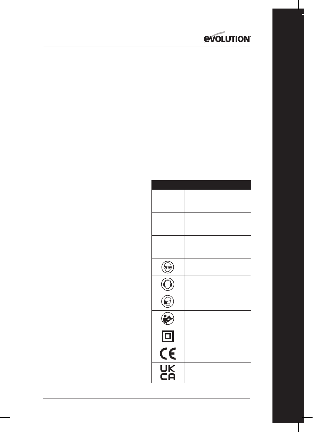
(1.8)
Symbol Description
V
Volts
A
Amperes
Hz
Hertz
Min
-1
/ RPM
Speed
~
Alternating Current
n
o
No Load Speed
Wear Safety Goggles
Wear Ear Protection
Wear Dust Protection
Read Instructions
Double Insulated
CE Certification
UKCA Certification
6
www.evolutionpowertools.com
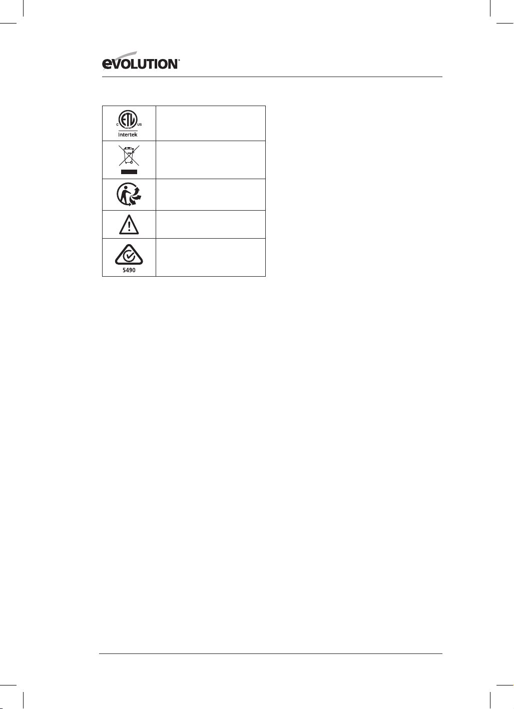
ETL Certification
Waste Electrical &
Electronic Equipment
Triman - Waste Collection
& Recycling
Warning
(RCM) Regulatory Compliance Mark
for electrical and electronic equipment.
Australian/New Zealand Standard
(1.9) INTENDED USE
OF THIS POWER TOOL
WARNING: This product is a Hand Operated
Circular Saw and has been designed to be
used with special Evolution blades. Only use
accessories designed for use in this machine
and/or those recommended specifically
by Evolution Power Tools Ltd.
When fitted with an appropriate blade
this machine can be used to cut:
Mild Steel, Aluminium, Wood
Note: Cutting galvanised steel may reduce
blade life.
(1.10) PROHIBITED USE
OF THIS POWER TOOL
WARNING: This product is a Hand Operated
Circular Saw and must only be used as such.
It must not be modified in any way, or used to
power any other equipment or drive any other
accessories other than those mentioned in this
Instruction Manual.
(1.11) WARNING: This machine is not intended
for use by persons (including children) with
reduced physical, sensory
or mental capabilities, or lack of experience
and knowledge, unless they have been given
supervision or instruction concerning the safe
use of the machine by a person responsible
for their safety and who is competent
in its safe use.
Children should be supervised to ensure
that they do not have access to, and are
not allowed to play with, this machine.
(1.12) ELECTRICAL SAFETY
This machine is fitted with the correct
moulded plug and mains lead for the
designated market. If the supply cord is
damaged, it must be replaced by a special
cord or assembly available from the
manufacturers or its service agent.
(1.13) OUTDOOR USE
WARNING: For your protection if this tool is to
be used outdoors it should not be exposed to
rain, or used in damp locations. Do not place
the tool on damp surfaces. Use a clean, dry
workbench if available. For added protection
use a residual current device (R.C.D.) that will
interrupt the supply if the leakage current to
earth exceeds 30mA for 30ms. Always check
the operation of the residual current device
(R.C.D.) before using the machine.
If an extension cable is required it must be a
suitable type for use outdoors and so labelled.
The manufacturers instructions should be
followed when using an extension cable.
(2.1) GENERAL SAFETY
INSTRUCTIONS
(These General Power Tool Safety Instructions
are as specified in EN 62841-1: 2015).
WARNING: Read all safety warnings and
instructions. Failure to follow the warnings
and instructions may result in electric shock,
fire and/ or serious injury.
Save all warnings and instructions for
future reference. The term “power tool” in
the warnings refers to your mains-operated
(corded) power tool or battery-operated
(cordless) power tool.
(2.2) 1) General Power Tool
Safety Warnings [Work area safety]
a) Keep work area clean and well lit.
Cluttered or dark areas invite accidents.
b) Do not operate power tools in explosive
atmospheres, such as in the presence of
flammable liquids, gasses or dust. Power

7
www.evolutionpowertools.com
EN
tools create sparks which may ignite the
dust or fumes.
c) Keep children and bystanders away while
operating power tool. Distractions can cause
you to lose control.
(2.3) 2) General Power Tool Safety Warnings
[Electrical Safety]
a) Power tool plugs must match the outlet.
Never modify the plug in any way. Do
not use any adapter plugs with earthed
(grounded) power tools. Unmodified plugs
and matching outlets will reduce risk of
electric shock.
b) Avoid body contact with earthed or
grounded surfaces, such as pipes, radiators,
ranges and refrigerators. There is an
increased risk of electric shock if your body is
earthed or grounded.
c) Do not expose power tools to rain or wet
conditions. Water entering a power tool will
increase the risk of electric shock.
d) Do not abuse the cord. Never use the cord
for carrying, pulling or unplugging the power
tool. Keep cord away from heat, oil, sharp
edges or moving parts. Damaged or entangled
cords increase the risk of electric shock.
e) When operating a power tool outdoors,
use an extension cord suitable for outdoor
use. Use of a cord suitable for outdoor use
reduces the risk of electric shock.
f) If operating a power tool in a damp
location is unavoidable, use a residual
current device (RCD) protected supply.
Use of an RCD reduces the risk of
electric shock.
Note: The product is intended for use
only in premises having a service current
capacity≥100A per phase, supplied from a
distribution network having a nominal voltage
of 230V. If required, contact the electricity
company to ensure that the mains current
carrying capacity at the connection point
to the public power grid is adequate for
connecting the product.
(2.4) 3) General Power Tool Safety Warnings
[Personal Safety].
a) Stay alert, watch what you are doing and
use common sense when operating a power
tool. Do not use a power tool while you are
tired or under the influence of drugs, alcohol
or medication. A moment of inattention while
operating power tools may result in serious
personal injury.
b) Use personal protective equipment.
Always wear eye protection. Protective
equipment such as dust masks, non-skid safety
shoes, hard hat or hearing protection used
for appropriate conditions will reduce
personal injuries.
c) Prevent unintentional starting. Ensure the
switch is in the off-position before connecting
to power source and or battery pack, picking
up or carrying the tool. Carrying power tools
with your finger on the switch or energising the
power tools that have the switch on
invites accidents.
d) Remove any adjusting key or wrench
from blade bolt before turning the power
tool on. A wrench or key left attached to a
rotating part of a power tool may result in
personal injury.
e) Do not overreach. Keep proper footing and
balance at all times. This enables better control
of the power tool in unexpected situations.
f) Dress properly. Do not wear loose clothing
or jewellery. Keep your hair, clothing and gloves
away from moving parts. Loose clothes, jewellery
or long hair can be caught in moving parts.
g) If devices are provided for the connection
of dust extraction and collection facilities,
ensure that these are connected and
properly used. Use of dust collection can
reduce dust-related hazards.
h) Do not let familiarity gained from
frequent use of tools allow you to become
complacent and ignore tool safety
principles. A careless action can cause severe
injury within a fraction of a second.
(2.5) 4) General Power Tool Safety Warnings
[Power tool use and care].
a) Do not force the power tool. Use the
correct power tool for your application. The
correct power tool will do the job better and
safer at a rate for which it was designed.
b) Do not use the power tool if the switch
does not turn it on or off. Any power tool
that cannot be controlled with the switch
is dangerous and must be repaired.
c) Disconnect the power tool from the
power source from the power tool before

8
www.evolutionpowertools.com
making any adjustments, changing
accessories, or storing power tools. Such
preventative safety measures reduce the risk
of starting the power
tool accidentally.
d) Store idle power tools out of the reach
of children and do not allow persons
unfamiliar with the power tool or these
instructions to operate the power tool.
Power tools are dangerous in the hands of
untrained users.
e) Maintain power tools. Check for
misalignment or binding of moving parts,
breakage of moving parts and any other
condition that may affect the power tools
operation. If damaged, have the power tool
repaired before use. Many accidents are
caused by poorly maintained power tools.
f) Keep cutting tools sharp and clean.
Properly maintained cutting tools with
sharp cutting edges are less likely to bind
and are easier to control.
g) Use the power tool, accessories and
tool bits etc. in accordance with these
instructions, taking into account the
working conditions and the work to
be performed. Use of the power tool for
operations different from those intended
could result in a hazardous situation.
h) Keep handles and grasping surfaces dry,
clean and free from oil and grease. Slippery
handles and grasping surfaces do not allow
for safe handling and control of the tool in
unexpected situations.
(2.6) 5) General Power Tool
Safety Warnings [Service]
a) Have your power tool serviced by a
qualified repair person using only identical
replacement parts. This will ensure that the
safety of the power tool is maintained.
(2.7) HEALTH ADVICE
WARNING: When using this machine,
dust particles may be produced. In some
instances, depending on the materials you
are working with, this dust can be particularly
harmful. If you suspect that paint on the
surface of material you wish to cut contains
lead, seek professional advice. Lead based
paints should only be removed by
a professional and you should not
attempt to remove it yourself.
Once the dust has been deposited on
surfaces, hand to mouth contact can result
in the ingestion of lead. Exposure to even
low levels of lead can cause irreversible brain
and nervous system damage. The young and
unborn children are particularly vulnerable.
You are advised to consider the risks
associated with the materials you are working
with and to reduce the risk of exposure.
As some materials can produce dust that may
be hazardous to your health, we recommend
the use of an approved face mask with
replaceable filters when using this machine.
You should always:
• Work in a well-ventilated area.
• Work with approved safety equipment, such
as dust masks that are specially designed to
filter microscopic particles.
(2.8) WARNING: the operation of any power
tool can result in foreign objects being thrown
towards your eyes, which could result in
severe eye damage. Before beginning power
tool operation, always wear safety goggles
or safety glasses with side shield or a full face
shield where necessary.
SAFETY INSTRUCTIONS FOR ALL SAWS
[Cutting procedures]
a) DANGER: Keep hands away from cutting
area and the blade. Keep your second
hand on auxiliary handle, or motor
housing. If both hands are holding the saw,
they cannot be cut by the blade.
b) Do not reach underneath the workpiece.
The guard cannot protect you from the blade
below the workpiece.
c) Adjust the cutting depth to the thickness of
the workpiece. Less than a full tooth of the blade
teeth should be visible below the workpiece.
d) Never hold the workpiece in your hands
or across your leg while cutting. Secure
the workpiece to a stable platform. It is
important to support the work properly to
minimise body exposure, blade binding, or
loss of control.
e) Hold the power tool by insulated
gripping surfaces, when performing an

9
www.evolutionpowertools.com
EN
operation where the cutting tool may
contact hidden wiring or its own cord.
Contact with a “live” wire will also make
exposed metal parts of the power tool ‘live’
and could give the operator an electric shock.
f) When ripping, always use a rip fence
or straight edge guide. This improves the
accuracy of cut and reduces the chance of
blade binding.
g) Always use blades with correct size and
shape (diamond versus round) of arbour
holes. Blades that do not match the mounting
hardware of the saw will run off-centre,
causing loss of control.
h) Never use damaged or incorrect blade
washers or bolt. The blade washers and
bolt were specially designed for your saw, for
optimum performance and safety of operation.
(3.2) [Kickback causes and
related warnings]
Kickback is a sudden reaction to a pinched,
jammed or misaligned saw blade, causing
an uncontrolled saw to lift up and out of the
workpiece toward the operator;
When the blade is pinched or jammed tightly
by the kerf closing down, the blade stalls and
the motor reaction drives the unit rapidly back
toward the operator;
If the blade becomes twisted or misaligned
in the cut, the teeth at the back edge of the
blade can dig into the top surface of the wood
causing the blade to climb out of the kerf and
jump back toward the operator.
(3.3)
Kickback is the result of saw misuse and/or
incorrect operating procedures or conditions
and can be avoided by taking proper
precautions as given below.
a) Maintain a firm grip with both hands on
the saw and position your arms to resist
kickback forces. Position your body to
either side of the blade, but not in line
with the blade. Kickback could cause the
saw to jump backwards, but kickback forces
can be controlled by the operator, if proper
precautions are taken.
b) When blade is binding, or when
interrupting a cut for any reason, release
the trigger and hold the saw motionless
in the material until the blade comes to a
complete stop. Never attempt to remove the
saw from the work or pull the saw backward
while the blade is in motion or kickback may
occur. Investigate and take corrective actions
to eliminate the cause of blade binding.
c) When restarting a saw in the workpiece,
centre the saw blade in the kerf so that the saw
teeth are not engaged into the material. If a saw
blade binds, it may walk up or kickback from the
workpiece as the saw is restarted.
d) Do not use dull or damaged blades.
Unsharpened or improperly set blades produce
narrow kerf causing excessive friction, blade
binding and kickback.
e) Blade depth and bevel adjusting locking
levers must be tight and secure before making
a cut. If the blade adjustment shifts while cutting
it may cause binding and kickback.
f) Blade depth and bevel adjusting locking
levers must be tight and secure before
making the cut. If blade adjustment shifts
while cutting, it may cause binding and
kickback.
g) Use extra caution when sawing into
existing walls or other blind areas. The
protruding blade may cut objects that can
cause kickback.
LOWER GUARD FUNCTION
a) Check the lower guard for proper closing
before each use. Do not operate the saw if
the lower guard does not move freely and
close instantly. Never clamp or tie the lower
guard into the open position. If the saw is
accidentally dropped, the lower guard may be
bent. Raise the lower guard with the retracting
handle and make sure it moves freely and does
not touch the blade or any other part, in all
angles and depths of cut.
b) Check the operation of the lower guard
spring. If the guard and the spring are not
operating properly, they must be serviced
before use. Lower guard may operate
sluggishly due to damaged parts, gummy
deposits, or a build-up of debris.
c) The lower guard may be retracted
manually only for special cuts such as

10
www.evolutionpowertools.com
“plunge cuts” and “compound cuts”.
Raise the lower guard by the retracting
handle and as soon as the blade enters the
material, the lower guard must be released.
For all other sawing, the lower guard should
operate automatically.
d) Always observe that the lower guard is
covering the blade before placing the saw
down on bench or floor. An unprotected,
coasting blade will cause the saw to walk
backwards, cutting whatever is in its path. Be
aware of the time it takes for the blade to stop
after switch is released.
ADDITIONAL SAFETY
INSTRUCTIONS
FOR CIRCULAR SAWS
a) Do not use High Speed Steel (HSS)
saw blades.
b) Inspect the machine and the blade
before each use. Do not use deformed,
cracked, worn or otherwise damaged blades.
c) Never use the saw without the original
guard protection system. Do not lock
the moving guard in the open position.
Ensure that the guard operates freely
without jamming.
d) Only use blades that comply with the
characteristics specified in this manual.
Before using accessories, always compare
the maximum allowed RPM of the
accessory with the RPM of the machine.
e) Do not use any abrasive wheels.
f) Use only blade diameter(s) in accordance
with the markings.
(3.4) WARNING: If any parts are missing, do
not operate your machine until the missing
parts are replaced. Failure to follow this rule
could result in serious personal injury.
(4.1) GETTING STARTED - UNPACKING
Caution: This packaging contains sharp objects.
Take care when unpacking. Remove the machine,
together with the accessories supplied from the
packaging. Check carefully to ensure that the
machine is in good condition and account for all
the accessories listed in this manual. Also make
sure that all the accessories are complete.
If any parts are found to be missing,
the machine and its accessories should be
returned together in their original packaging to
the retailer.
Do not throw the packaging away; keep it safe
throughout the warranty period. Dispose of the
packaging in an environmentally responsible
manner. Recycle if possible.
Do not let children play with empty plastic bags
due to the risk of suffocation.
(4.3) EVOLUTION INSTRUCTION
MANUALS
Evolution Power Tools provides each product
with an Instruction Manual.
Each dedicated manual is carefully constructed
and designed to provide easily accessible and
useful information regarding the safe use, care
and maintenance of the product. Referencing
the information contained within the manual
will allow the operator to fully and safely
exploit the potential of the machine.
Evolutions policy of continual product
development may mean that, very
occasionally, the contents of a manual may not
completely reflect the latest improvements or
upgrades that have been incorporated into a
particular product. Upgrades/improvements
to the specification of a product could come
about as a consequence of technological
advances or changes to the legislative
framework of the receiving country, etc.
If you are at all unsure about any aspect of
the use, care or maintenance of an Evolution
product, contact the relevant Evolution
helpline where up to date information and
extra advice will be available.
11
www.evolutionpowertools.com
EN
13
15
4
14
5
1
3
8
9
10
11
6
7
2
16
12
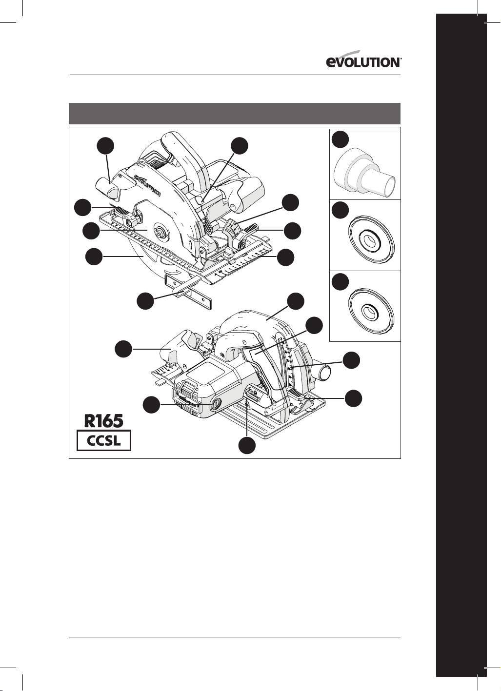
1. CUT MATERIAL EJECTION PORT
2. THUMB LEVER
3. MULTI-MATERIAL TCT BLADE
4. LOWER BLADE GUARD
5. PARALLEL EDGE GUIDE
6. ERGONOMIC FRONT HANDLE
7. CARBON BRUSHES
8. 8MM HEX KEY (BLADE CHANGE)
9. DEPTH ADJUSTMENT LOCKING LEVER
10. DEPTH SCALE
11. REAR HANDLE
12. UPPER BLADE GUARD
13. PRECISION ENGINEERED SOLE PLATE
14. THUMB LEVER
15. PROTRACTOR SCALE
16. ARBOR LOCK BUTTON
17. DUST PORT CONNECTOR
18. 25/32” INNER BLADE FLANGE
19. 5/8” INNER BLADE FLANGE
USA
17
18
19

12
www.evolutionpowertools.com
USA
1. CUT MATERIAL EJECTION PORT
2. THUMB LEVER
3. MULTI-MATERIAL TCT BLADE
4. LOWER BLADE GUARD
5. PARALLEL EDGE GUIDE
6. ERGONOMIC FRONT HANDLE
7. CARBON BRUSHES
8. 5/16” HEX KEY (BLADE CHANGE)
9. DEPTH ADJUSTMENT LOCKING LEVER
10. DEPTH SCALE
11. REAR HANDLE ON/OFF SWITCH
12. UPPER BLADE GUARD
13. PRECISION ENGINEERED SOLE PLATE
14. BEVEL ADJUSTMENT THUMB LEVER
15. PROTRACTOR SCALE
16. ARBOR LOCK BUTTON
17. LED LIGHT
18. DUST PORT CONNECTOR
19. 25/32” INNER BLADE FLANGE
20. 5/8” INNER BLADE FLANGE
13
15
17
18
19
20
4
14
5
1
3
8
9
10
11
6
7
2
16
12
13
www.evolutionpowertools.com
EN
USA
1. CUT MATERIAL EJECTION PORT
2. THUMB LEVER
3. MULTI-MATERIAL TCT BLADE
4. LOWER BLADE GUARD
5. PARALLEL EDGE GUIDE
6. ERGONOMIC FRONT HANDLE
7. CARBON BRUSHES
8. 5/16” HEX KEY (BLADE CHANGE)
9. DEPTH ADJUSTMENT LEVER
10. DEPTH SCALE
11. REAR HANDLE ON/OFF SWITCH
12. UPPER BLADE GUARD
13. PRECISION ENGINEERED TRACK
COMPATIBLE SOLE PLATE
14. THUMB LEVER
15. REAR PROTRACTOR SCALE
16. ARBOR LOCK BUTTON
17. DUST PORT CONNECTOR
18. 25/32” INNER BLADE FLANGE
19. 5/8” INNER BLADE FLANGE
20. TRACK ADJUST TURN BUTTONS
21. REAR BEVEL THUMB SCREW
22. 3x 13-3/8” TRACK
23. 4x TRACK CONNECTOR BARS
24. 1/8” HEX KEY (TRACK)
13
20
15
17
18
19
4
14
5
1
3
8
9
10
21
11
6
7
2
16
12
22 23 24

14
www.evolutionpowertools.com
USA
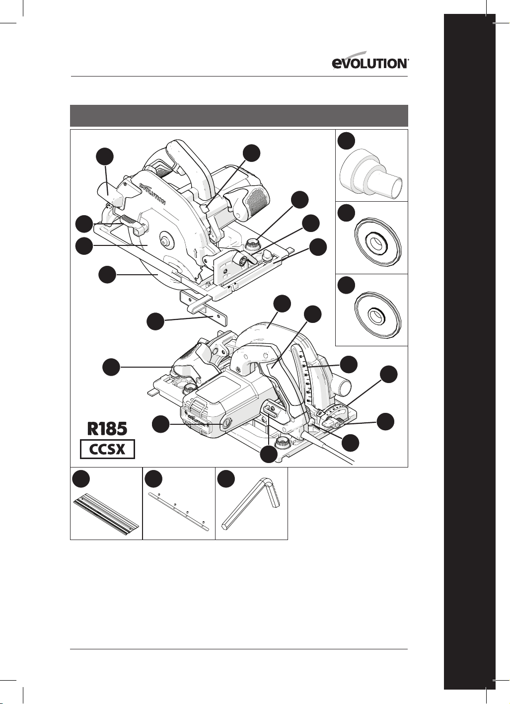
1. CUT MATERIAL EJECTION PORT
2. THUMB LEVER
3. MULTI-MATERIAL TCT BLADE
4. LOWER BLADE GUARD
5. PARALLEL EDGE GUIDE
6. ERGONOMIC FRONT HANDLE
7. CARBON BRUSHES
8. 8MM HEX KEY (BLADE CHANGE)
9. DEPTH ADJUSTMENT LOCKING LEVER
10. DEPTH SCALE
11. REAR HANDLE ON/OFF SWITCH
12. UPPER BLADE GUARD
13. PRECISION ENGINEERED TRACK
COMPATIBLE SOLE PLATE
14. THUMB LEVER
15. REAR PROTRACTOR SCALE
16. ARBOR LOCK BUTTON
17. LED LIGHT
18. DUST PORT CONNECTOR
19. 25/32” INNER BLADE FLANGE
20. 5/8” INNER BLADE FLANGE
21. TRACK ADJUST TURN BUTTONS
22. REAR BEVEL THUMB SCREW
13
21
15
17
18
19
20
4
14
5
1
3
8
9
10
22
11
6
7
2
16
12

15
www.evolutionpowertools.com
EN
13
15
4
14
5
1
3
8
9
10
11
6
7
2
16
12
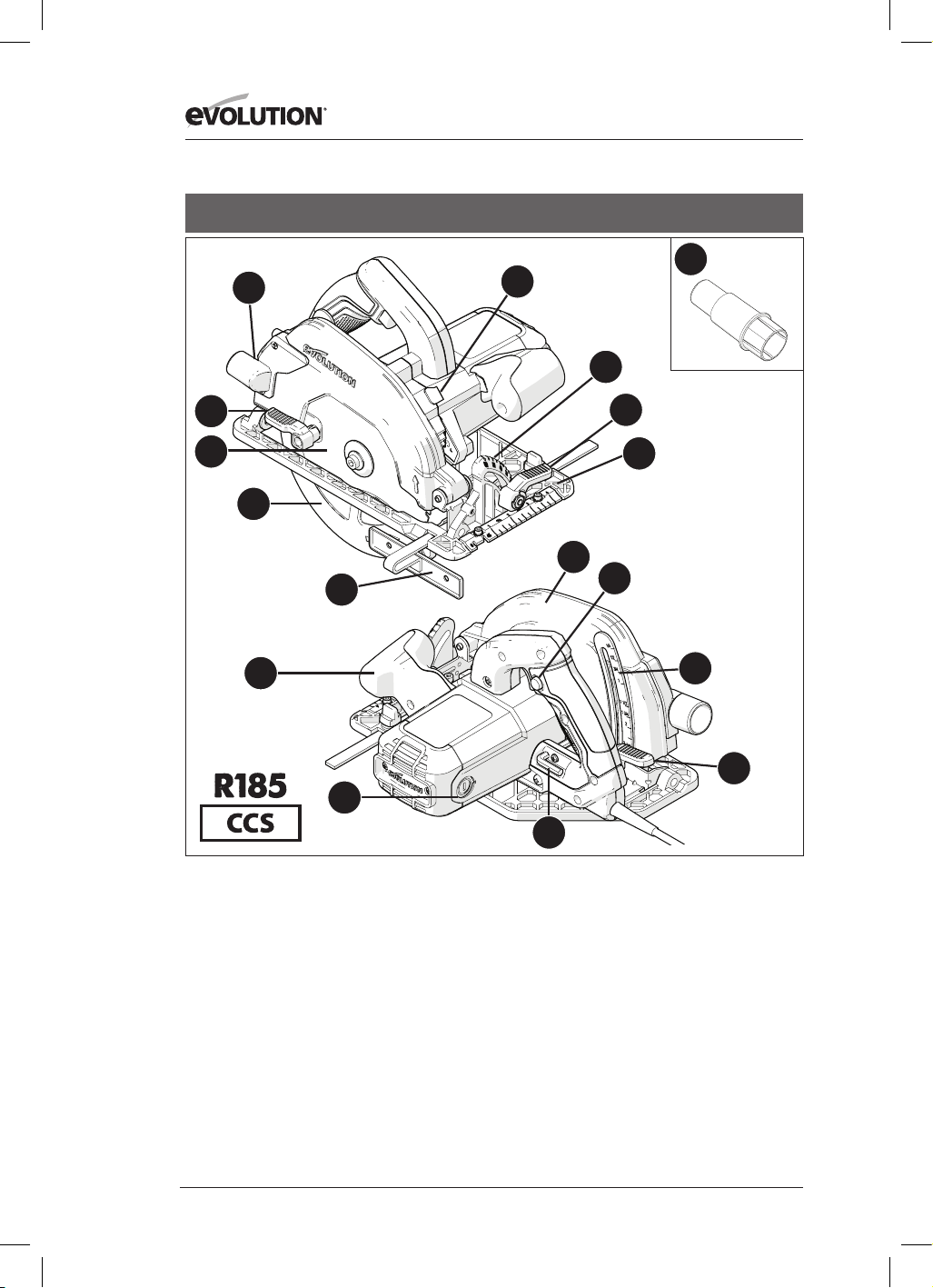
1. CUT MATERIAL EJECTION PORT
2. THUMB LEVER
3. MULTI-MATERIAL TCT BLADE
4. LOWER BLADE GUARD
5. PARALLEL EDGE GUIDE
6. ERGONOMIC FRONT HANDLE
7. CARBON BRUSHES
8. 8MM HEX KEY (BLADE CHANGE)
9. DEPTH ADJUSTMENT LOCKING LEVER
10. DEPTH SCALE
11. REAR HANDLE INCORPORATING
SAFETY START ON/OFF SWITCH
12. UPPER BLADE GUARD
13. PRECISION ENGINEERED SOLE PLATE
14. THUMB LEVER
15. PROTRACTOR SCALE
16. ARBOR LOCK BUTTON
UK / EU / AUS
16
www.evolutionpowertools.com
1. CUT MATERIAL EJECTION PORT
2. THUMB LEVER
3. MULTI-MATERIAL TCT BLADE
4. LOWER BLADE GUARD
5. PARALLEL EDGE GUIDE
6. ERGONOMIC FRONT HANDLE
7. CARBON BRUSHES
8. 8MM HEX KEY (BLADE CHANGE)
9. DEPTH ADJUSTMENT LOCKING LEVER
10. DEPTH SCALE
11. REAR HANDLE INCORPORATING
SAFETY START ON/OFF SWITCH
12. UPPER BLADE GUARD
13. PRECISION ENGINEERED SOLE PLATE
14. THUMB LEVER
15. PROTRACTOR SCALE
16. ARBOR LOCK BUTTON
17. DUST PORT CONNECTOR
UK / EU
13
15
17
4
14
5
1
3
8
9
10
11
6
7
2
16
12

17
www.evolutionpowertools.com
EN
13
18
15
17
20
21
22
4
14
5
1
3
8
9
10
19
11
6
7
2
16
12
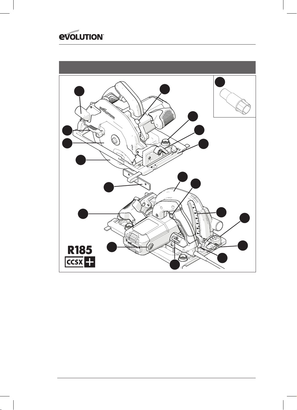
1. CUT MATERIAL EJECTION PORT
2. THUMB LEVER
3. MULTI-MATERIAL TCT BLADE
4. LOWER BLADE GUARD
5. PARALLEL EDGE GUIDE
6. ERGONOMIC FRONT HANDLE
7. CARBON BRUSHES
8. 8MM HEX KEY (BLADE CHANGE)
9. DEPTH ADJUSTMENT LOCKING LEVER
10. DEPTH SCALE
11. REAR HANDLE INCORPORATING
SAFETY START ON/OFF SWITCH
12. UPPER BLADE GUARD
13. PRECISION ENGINEERED TRACK
COMPATIBLE SOLE PLATE
14. THUMB LEVER
15. REAR PROTRACTOR SCALE
16. ARBOR LOCK BUTTON
17. DUST PORT CONNECTOR
18. TRACK ADJUST TURN BUTTONS
19. REAR BEVEL THUMB SCREW
20. 3x 340mm TRACK
21. 4x TRACK CONNECTOR BARS
22. 3mm HEX KEY
UK / EU
18
www.evolutionpowertools.com
UK / EU
1. CUT MATERIAL EJECTION PORT
2. THUMB LEVER
3. MULTI-MATERIAL TCT BLADE
4. LOWER BLADE GUARD
5. PARALLEL EDGE GUIDE
6. ERGONOMIC FRONT HANDLE
7. CARBON BRUSHES
8. 8MM HEX KEY (BLADE CHANGE)
9. DEPTH ADJUSTMENT LOCKING LEVER
10. DEPTH SCALE
11. REAR HANDLE INCORPORATING
SAFETY START ON/OFF SWITCH
12. UPPER BLADE GUARD
13. PRECISION ENGINEERED TRACK
COMPATIBLE SOLE PLATE
14. THUMB LEVER
15. REAR PROTRACTOR SCALE
16. ARBOR LOCK BUTTON
17. DUST PORT CONNECTOR
18. TRACK ADJUST TURN BUTTONS
19. REAR BEVEL THUMB SCREW
13
18
15
17
4
14
5
1
3
8
9
10
19
11
6
7
2
16
12

19
www.evolutionpowertools.com
EN
Fig. 3Fig. 2
Fig. 4
Fig. 1
Fig. 8
Fig. 6Fig. 5
Fig. 9
Fig. 10
Fig. 7a Fig. 7b Fig. 7c

20
www.evolutionpowertools.com
Fig. 11
Fig. 12
Fig. 13
Fig. 14
Fig. 15
Fig. 16
Fig. 17 Fig. 18
Fig. 21Fig. 20
Fig. 19
Fig. 22
1 -2mm

21
www.evolutionpowertools.com
EN
Fig. 27Fig. 26
Fig. 25
Fig. 30 Fig. 31
Fig. 34
Fig. 24Fig. 23
US Dust Port Connector
EU Dust Port Connector
Fig. 28
Fig. 29
Fig. 32 Fig. 33

22
www.evolutionpowertools.com
(10) PREPARATION
WARNING: Always disconnect the machine
from the power source before making any
adjustments.
Note: These machines are equipped with an
approved power cord and plug for the intended
country of use. Do not alter or modify the power
cord.
(10.1) INSTALLING /
REMOVING A BLADE
WARNING: Use only genuine Evolution blades
(or those approved by Evolution Power Tools),
which are designed for use in these machines.
Ensure that the maximum speed of the blade is
compatible with the machine. Only perform this
operation with the machine disconnected from
the power supply.
Note: It is recommended that the operator
considers wearing protective gloves when
handling the blade during installation or when
changing the machines blade.
• Locate the supplied Blade Change Hex Key
which is housed in the onboard storage facility
(similarly position on all machines). (Fig. 1)
• Place saw on a level, secure surface.
Note: All machines can, with care, be balanced on
the flat end of the motor housing casing, (Fig. 2)
making access to the blade and blade fixings very
convenient.
• Locate the machines arbor lock button (which
is similarly positioned on all machines). Lock
the machines arbor by operating the arbor
lock button. (Fig. 3).
Note: Slowly rotating the blade by hand, whilst
gently pressing the arbor lock button will aid
arbor lock engagement.
• Using the Hex Key, loosen and remove the
arbor socket headed screw, associated fixings,
and outer blade drive flange. (Fig. 4)
Note: The socket headed arbor screw is equipped
with a standard screw thread.
Turn the screw clockwise to tighten. Turn the
screw counter clockwise to loosen.
• Safely store the outer blade flange and
associated fixings.
• Rotate the lower blade guard up into the
upper blade guard using the manual thumb
lever. (Fig. 5)
• Carefully remove the blade (if fitted) from
the machine.
• Thoroughly clean inner and outer blade
drive flanges.
Note: The inner blade flange can be left in
place if desired, but it should be checked and
thoroughly cleaned. If it is removed from the
machine it must be replaced back in the same
orientation as it was before removal.
• Thoroughly clean the blade around the bore
area (both surfaces) where the blade flanges
will touch and clamp the blade.
• Install the (new) blade.
• Ensure that the direction of rotation arrows
printed on the blade, match the direction
of rotation arrows found on the machines
upper and lower blade guards. (Fig. 6)
• Reinstall the outer drive flange, the
socket headed arbor screw, and its
associated fixings.
Note: The outer drive flange has a specially
machined bore which incorporates two
opposed ‘flats.’ (Fig. 7a) These ‘flats’ engage
with two complimentary ‘flats’ machined into
the machines arbor shaft.
• Re-engage the arbor lock and tighten the
arbor socket headed screw securely using
the Hex Key.
• Release the arbor lock button
• Return the Hex Key to its dedicated storage
position.
• Check that the arbor lock has fully released
by manually rotating the blade.
• Check the operation of the lower
blade guard.
Note: For North American market only, a dual
side arbor flange is included, to allow 1” bore
blades (Fig. 7b) and 5/8” bore blades (Fig. 7c).
(11) PARALLEL EDGE GUIDE
A Parallel Edge Guide (Fig. 8) which can be
particularly helpful when rip cutting, is supplied
with all CCS machines. The guide can be fitted
to the front of the sole plate.
The guides arm should be inserted through the
rectangular slots positioned at either side (front)
of the pressed steel sole plate, and slid under
the centrally located adjustment locking screw.
(Fig. 9)
Note: The Parallel Edge Guide can be fitted on
either side of the sole plate.

23
www.evolutionpowertools.com
EN
WARNING: Only fit and adjust the Guide with
the machine disconnected from the power
supply.
Note: The arm of the Parallel Edge Guide
must pass through all of the rectangular slots
provided in the sole plate.
WARNING: It is potentially dangerous to install,
and try to use the Edge Guide with the arm
passing through only one (1) of the machined
rectangular sole plate slots.
Adjust the edge guide so that it is at the
required distance from the blade and tighten
the adjusting screw. Check that the edge guide
is parallel to the saw blade.
(12) CUTTING DEPTH ADJUSTMENT
Note: All CCS machines share the same general
depth adjustment fixtures/fittings and employ
the same basic technique for setting the blade
depth.
• Loosen the Depth Adjustment Locking
Mechanism by pulling the operating lever
upwards. (Fig. 10)
• Adjust/re-position the sole plate to give the
required cutting depth (the amount by which
the blade protrudes through the sole plate).
Note: A depth scale can be found on the depth
adjustment quadrant, with a corresponding
index mark incorporated into the adjacent area
of the machines upper blade guard. (Fig. 11)
Using these features can aid rapid setting.
Note: Although the depth scale and index mark
are very useful, enabling rapid depth setting,
using them should always be regarded as a
guide to the setting achieved.
If a very precise depth of cut is required, then
the blade setting should be checked with an
engineers precision ruler (not supplied) or
similar and adjusted accordingly.
• In most cases the cutting depth should be set
at the thickness of the material to be cut plus
the depth of half of a saw tooth (tip of the
tooth to the tooth root). (Fig.12)
• Tighten the Depth Adjustment Locking
Mechanism by pushing the operating
lever downwards to securely to lock in the
machine in the required position.
(13) CUTTING ANGLE
(BEVEL) ADJUSTMENT
All CCSL & CCSX machines have the facility to
tilt the blade through (up to) 45˚ and all CCS
machines have the facility to tilt the blade
through (up to) 60˚ to the left hand side.
Bevel cuts are therefore possible.
Note: The blade is at the vertical position when
the protractor scale reads 0˚.
Note: A protractor scale (0˚- 45˚ or 0˚- 60˚) is
incorporated on the Bevel Locking quadrant
found at the front of the soleplate. Using this
will aid rapid bevel angle setting but should be
regarded as a guide only.
If a very precise bevel angle is required, then
the blade setting should be checked using a
vernier angle gauge (not supplied) and adjusted
accordingly.
• Loosen the Bevel Locking Mechanism found
at the front of the machine, by pulling the
lever upwards. (Fig. 13)
• Tilt the blade to the required angle as
indicated on the quadrant protractor scale.
(Fig. 14)
• Tighten the Bevel Locking Mechanism
securely when the desired bevel angle
has been achieved by pushing the lever
downwards.
(14) OPERATING ADVICE
(PRE OPERATION CHECKS)
Note: As all operating environments will be
unique and diverse, Evolution Power Tools offers
the following general advice on safe operational
procedures and practices for the consideration
of the operator.
This advice cannot be exhaustive as Evolution
has no influence on the type of workshops or
working environments in which these machines
may be used.
We recommend that the operator seeks advice
from a competent authority or the workshop
supervisor if they are at unsure of any aspect of
using these machines.
It is important that routine safety checks are
carried out (at each time of usage) before the
operator uses the machine.

24
www.evolutionpowertools.com
WARNING: These pre-use safety checks should
be carried out with the machine disconnected
from the mains power supply.
• Check that all safety guards are operating
correctly, and that all adjustment handles/
screws are securely tightened.
• Check that the blade is secure and installed
correctly. Also check that it is the correct
blade for the material being cut.
• Check the integrity of the power cord.
• Whenever possible clamp the workpiece to a
rigid support structure such as a workbench,
saw horse or similar.
• The operator should always be aware of the
position and routing of the power cable.
(15) PPE
• The operator should wear all relevant PPE
(Personal Protection Equipment) necessary
for the task ahead.
This could include safety glasses,,full face
mask, dust masks, safety shoes etc.
Note: All CCS series machines are equipped
with a cutting line debris blower. This directs
air from a motor driven fan towards the area to
the front of the blade, thus keeping the cutting
line relatively debris free. This feature will aid the
operator sight and follow the progress of the
saw blade along the cut, keeping any marking-
out lines visible.
WARNING: Any and all dust created is
potentially prejudicial to health.
Some materials can be particularly harmful, and the
operator should always wear a dust mask which is
suitable for the material being worked with.
Professional help and advice should be sought if
the operator is at all unsure about the potential
toxicity of the material to be cut.
WARNING: These machines must never be
used to cut Asbestos or any material that
contains, or is suspected to contain, Asbestos.
Consult/inform the relevant authorities,
and seek additional guidance if Asbestos
contamination is suspected.
(16) ON/OFF TRIGGER SWITCH
Note: All machines destined for the European
and Australian market are equipped with a
‘safety start’ trigger switch to enhance operator
safety. (Fig.15)
To start the motor:
• Push in the safety lock button on the side of
the handle with your thumb.
• Depress the trigger switch.
To stop the motor:
• Release the trigger switch.
WARNING: The motor should never be started
with the saw blade in direct contact with any
surface of the workpiece.
Note: Machines destined for the North
American market are fitted with an ON/OFF
Trigger switch which does not incorporate a
‘safety start’ trigger switch.
WARNING: If the saw is ‘live’ (LED Light ‘ON’),
avoid unintentionally starting the motor when
picking up the machine from a workbench or
similar. Accidentally depressing the ON/OFF
Trigger switch (positioned in the main handle)
when picking up the machine from rest will
cause the motor to start.
CUTTING TRACKS
Evolution CCSX series machines (refer
to the Specification Page for applicable
models) have been engineered and
featured in such a way as to make them
Cutting Track compatible.
Note: Any circular saw that is capable of being
used with a Cutting Track will have a channel
along the under surface of the sole plate (Fig. 16)
Evolution machines so equipped can be
attached to, and used with most Cutting Tracks
(Guides) currently available.
Note: Consult the documentation supplied
with the track by the track manufacturer. The
supplied documentation will normally give
the assembly instructions for the track, as well
as information regarding the safe working
practices that need to be employed when
using such equipment.
Cutting Tracks can be employed where:
• The use of a chop or circular saw could
present Health and Safety (H&S) or other
practical workplace issues. For example
when working on a construction site
where very close and accurate control may
be necessary, (working on a roof or on a
scaffolding platform, etc.) using a cutting

25
www.evolutionpowertools.com
EN
track may provide the user with some extra
(and safe) operational possibilities.
• Accurate cuts across or along large
workpieces are required. For example on
frames, doors, large boards or wall panels,
etc, a cutting track/guide could eliminate the
need to use a circular saw in ‘free hand’ mode.
Note: Evolution’s cutting track compatible
machines have two (2) cams which project into
the sole plate channel (one at each end).
‘Turn-buttons’ (Fig. 17) allow the operator to
rotate these cams.
Adjusting these cams will reduce slightly the
effective width of the sole plate channel.
This could be necessary to accommodate any
slight variation of rail width that can occur
during the manufacture of the track extrusion.
Track rail widths produced by different track
manufacturers may also vary slightly.
Note: The operator should adjust these cams so
that when the machine is placed correctly on
a track it can be moved forwards or backwards
easily and smoothly but without any lateral
movement (wobble) being detectable.
EVOLUTION CUTTING TRACKS
Some Evolution machines (depending upon
the model and market destination) are
supplied with a Cutting Track.
Note: Evolution Cutting Tracks are available as a
customer purchase option. Contact your supplier
or Evolution Power Tools for further details.
THE TRACK
The Evolution Track system consists of two (2) or
three (3) precision extruded alloy sections.
(Fig. 18) These sections must be joined together
using the joining bars supplied. (Fig. 19)
To Join The Sections Together (Fig. 19):
• Slide the bars into the ‘T’ slots found on the
under surface of the extrusions.
• Ensure that an equal length (approximately)
of the bars is inserted into both of the
sections to be joined together.
• Tighten the socket headed grub-screws to
secure the sections together.
Note: It is important to leave a small gap
between joined sections of between 1 to 2mm.
This will ensure that when a circular saw is
placed upon and used with an Evolution Cross
Cutting Track it will slide smoothly along the
entire track length.
SAW TO TRACK COMMISSIONING
Note: The following guidelines refer to
Evolution circular saws and the Evolution
Cutting Track. Consult the information
supplied by the saw and/or the cutting track
manufacturers if a non-Evolution circular saw
or cutting track is to be used.
Before the first use of the Evolution Cutting
Track the Splinter Guard Strip (Fig. 21) needs to
match the saw and blade.
To match saw to track:
• Fully assemble the Cutting Track.
• Refer to the section entitled ‘Track
Positioning and Clamping’. Clamp the track
to an appropriate piece of spare or scrap
material.
• Set the saw blade to a depth suitable for the
scrap workpiece selected.
• Ensure that no obstructions are present
beneath the path of the blade.
• Refer to the section ‘Track Positioning and
Clamping’. Place the circular saw correctly
on the track.
• Start the motor and allow it to reach full
speed.
• Smoothly and slowly push the circular saw
along the full length of the track until the
blade has cut through the entire length of
the Splinter Guard Strip.
Note: This process will match a specific saw to
a specific track.
If a different saw is used on such a prepared
track, the Splinter Guard Strip may not provide
the same level of protection as the dedicated
saw to track configuration.
Note: The Splinter Guard Strip should be
regarded as a consumable item. Over time
it will wear and abrade and will therefore
need replacing. It may also need replacing if a
different circular saw or saw blade (one with a
different kerf width) from the original dedicated
configuration is to be used.
REPLACEABLE SPLINTER GUARD
STRIP
As a consumable item Replaceable Splinter

26
www.evolutionpowertools.com
Guard Strip should be checked at regular
intervals for damage or abrasion caused by ‘wear
and tear’. Replace the strip if any damage or
significant wear is apparent.
Replacement strips are available. Consult
your supplier or contact Evolution using the
appropriate helpline.
The Replaceable Splinter Guard Strip supplied
is a direct substitution to the fitted original.
Simply pull the old strip gently from the track
and replace with the new strip.
Note: If a new strip is fitted, the Saw to Track
matching process must be repeated.
EVOLUTION TRACK CLAMPS
(SOLD SEPARATELY)
The Evolution Speed Clamp (Fig. 22) is
purpose designed to work with the Evolution
Cutting Track.
Note: Extra clamps can be purchased from
Evolution Power Tools or your local supplier.
Evolution clamps fit into and can slide along
the ‘T’ slots found on the under surface of the
alloy extrusions. (Fig. 23)
This enables the operator to locate the clamps
(one is required at each end of the track) in
positions which afford the maximum security,
and rigidity of the Cutting Track to the
workpiece.
TRACK POSITIONING & CLAMPING
Note: The following guidelines are given as
advice. Evolution has no influence over the
working environments or conditions in which
this equipment is used.
WARNING: If this equipment is to be used on a
construction site, the operator should consult the
relevant person who has responsibility for Health
and Safety for further ‘on site’ specific safety
requirements or instructions.
• Mark out clearly the workpiece and particularly
the ‘line of cut’ along which the saw blade is
required to travel.
• Assemble the Cutting Track with as many
sections as required to span the workpiece
including an allowance for the overhang
needed.
• Using Evolution Speed Clamps (the preferred
option) or suitable ‘G’ clamps position the Track
on the workpiece and secure by tightening
the clamps.
• Ensure that the edge of the Splinter Guard
Strip runs exactly along the marked out
cutting line.
WARNING: The Cutting Track must overhang
the workpiece at the ‘lead in’ edge. (Fig. 24)
The lower blade guard will need to be
retracted manually and pivot upwards into the
upper blade guard as the circular saw is placed
on the track.
WARNING: In this position the blade is
exposed. DO NOT press the trigger until the
following safety checks have been carried out.
PERFORMING A CUT
Performing a cut using a cutting track is very
similar to ordinary cutting with a circular saw.
All of the safety procedures and protocols that
apply to the use of a circular saw will also apply
when such a saw is used in conjunction with a
cross cutting track.
The following guidelines, though not
comprehensive offer some general advice:
• Carry out a safety check to ensure that the
Cutting Track is securely fastened to the
workpiece, and that the workpiece itself is
secure and cannot move during a cut.
• Check to ensure that there are no
obstructions under the workpiece that
could inhibit or impede the progress of the
saw blade or be damaged by the saw blade.
• Ensure that the mains cable is routed in such
a way that it does not pose a trip (or any
other form) hazard. Check particularly that
the mains cable cannot come into contact
with the spinning blade of the saw.
• The operator should ensure that when they
are pushing the saw along the track they can
maintain a sure footing, good balance and
complete control at all times throughout the
cut. Particular caution should be exercised as
the saw blade exits the workpiece.
WARNING: Particularly if working at height
(other circumstances may also apply) ensure
that any cut material cannot fall away and
possibly injure a bystander. The operator may
have to consider some way of containing or
catching such cut material. Consult the person
responsible for site safety for specific guidance.
Note: The operator should consider
performing a practice run with the saw
disconnected from the mains supply to
confirm that the cutting procedure will be

27
www.evolutionpowertools.com
EN
completely safe throughout.
When the cut has been completed the
operator should release the ON/OFF Trigger
Switch and allow the motor to stop and the
blade to become stationary.
As the saw is lifted from the Cutting Track
and workpiece the lower blade guard will
automatically deploy covering the blade
completely.
DUST / DEBRIS COLLECTION
An adaptor nozzle (Fig. 25) can be fitted to all
CCS machines. Fitting the nozzle allows the
machine to be connected to a dust/debris
collection device.
Note: The exact design of the nozzle supplied
will vary depending upon type of model and
the market destination of the machine.
The supplied nozzle will accept a wide variety
of debris/dust collection devices currently
available. The nozzle should be fitted to the
Cut Material Ejection Port. (Fig. 26)
Note: A workshop dust/debris extraction
machine can be attached to the adaptor
nozzle if required. Follow the manufacturers
instructions if such a machine is fitted and
ensure that it is capable of handling the
ejected cut material.
LED LIGHT
Some of these machines (depending upon the
model and market destination) are equipped
with an automatic LED Light.
Note: If you are unsure of which features
are provided on your machine, consult the
Specification Page provided in this manual.
The LED Light is positioned to the left hand
(LH) side of the blade. (Fig. 27)
The beam from the LED will light up the left
hand side of the blade and also illuminate any
marking out lines present on the workpiece.
This should help the operator predict the path
of the blade through the workpiece and thus
aid efficiency, accuracy and safety.
Note: Operation of the LED Light is automatic.
As soon as the machine is connected to the
mains supply the LED will activate. This gives
the operator a clear visual indication that the
machine has been successfully connected to
the mains electrical supply, and is therefore
powered (is ‘live’) and ready for cutting
operations to commence.
Note: There are no user serviceable parts
incorporated within the LED Light assembly and
the beam direction is factory set. The protective
lens cover should be kept clear of dust etc.
(see Maintenance) to ensure the maximum
brightness of the projected beam is maintained.
WARNING: Only clean the lens cover with the
machine disconnected from the mains power
supply and the blade completely stationary.
INTEGRAL CUTTING AIDS
All Evolution circular saws are equipped with
various cutting aids or guides designed help
the operator achieve quick accurate cuts safely.
Note: Not all of the following features will
appear on every machine.
0˚ and 45˚ Line of Cut Guides (Fig. 28)
Located on the front edge of the machines sole
plate are two (2) small notches, which on some
machines are identified with an angular number.
These notches indicate the position of the blade
as it exits the workpiece when the bevel tilt angle
is set at 0˚ (blade vertical) or at an angle of 45˚.
Front of Blade Guide (Fig. 29)
Note: Evolution machines compatible with
Evolutions Cutting Track have a notch located on
the right hand edge (RH) of the sole plate casting.
This notch indicates the position of the front
edge of the blade when the blade is set at
maximum cutting depth. This feature can be
used when placing and positioning the saw on
a Cutting Track.
WARNING: It is important that the lower blade
guard or blade do not touch any surface of the
workpiece during the initial positioning of the
saw on the Cutting Track.
Ruler Guides (Fig. 30)
Ruler guides are present on some Evolution
circular saws. They are positioned along the
front and/or side edges of the sole plate.
These guides can give a useful approximate
position or prediction of the saw blade in the
workpiece.
SPECIALISED ADJUSTMENTS
Your Evolution machine has many precision
engineered components and settings, most of
which are factory set and adjusted to ensure
consistent long term accuracy.

28
www.evolutionpowertools.com
Maintenance and adjustment to these
components or settings will probably never be
needed. If maintenance or adjustment (after
considerable usage) is thought to be necessary
Evolution recommend that you contact the
technical helpline for further advice and
guidance.
Note: Certain adjustments procedures are
only possible with access to certain specialised
knowledge and/or equipment.
(17) GENERAL CUTTING ADVICE
WARNING: The operator must always be
aware of the position and routing of the power
cable. The cable must be routed in such a way
that there is no possibility of the blade coming
into contact with the mains cable.
The cable should not pose a trip (or any
other type) of hazard to the operator or any
bystanders.
• Do not force the machine.
• Allow the speed of the saw blade do the
work. Cutting performance will not be
improved by applying excessive pressure to
the machine and blade life will be reduced.
• When using the parallel edge guide, ensure
that it is parallel with the blade. The blade
and/or motor could become damaged if
the machine is used with an incorrectly
adjusted parallel edge guide.
• Place front edge of sole plate squarely on
the workpiece. Before starting the motor
ensure that the blade is not in contact with
the workpiece.
• When starting a cut, taking care to
introduce the blade to the material slowly,
so as not to damage blade teeth.
Note: Two (2) line of cut guides are provided
at the front of the sole plate of the CCSL
machine (for 0˚ and 45˚
bevel angles only).
• Use both hands to move the saw forwards
through the work piece.
• Apply smooth, constant pressure to move
the saw forwards through the workpiece.
Note: All CCS series machines have an
automatic lower blade guard which has a
specially shaped leading front edge. This
feature ensures that the blade guard retracts
smoothly and eortlessly as the machines
blade enters the workpiece. As the blade exits
the workpiece the lower blade guard will
automatically return to its normal position
covering the blade completely.
Note: On some occasions e.g. making a
plunge cut into a oor or wall etc. it may be
advantageous to retract the lower blade
guard manually.
A thumb operated lever is provided on
the lower blade guard. With care, a skilled
operator can retract the blade guard
manually, either partially or fully, allowing
plunge cuts to be made.
WARNING: If retracting the blade guard
manually great care must be taken to ensure
that the operators hand or ngers do not
touch any part of the machines blade.
When a cut has been completed:
• Release the ON/OFF Trigger switch.
• Allow the blade to come to a
complete stop.
• Remove the machine from the workpiece
allowing the lower blade guard to return to
its normal position covering the blade.
WARNING: If the motor should stop or stall
whilst a cut is being attempted release the
trigger switch immediately. Disconnect the
machine from the power supply and remove
the machine from the workpiece. Investigate
the cause of the problem and rectify if possible.
Only attempt to restart the motor when you
are absolutely sure that it is safe to do so.
CUT MATERIAL EJECTION PORT
WARNING: Do not use the dust bag and dust
port adaptor when cutting metallic materials
including wood with nails.
(18) MAINTENANCE & ADJUSTMENTS
The 0˚ (blade vertical) position can be adjusted.
WARNING: The machine must be
disconnected from the mains power supply
when attempting this procedure.
To check 0˚
position:
• Set the blade to the 0˚ position with the
tilting mechanism against its stop.
• Check the blade against the sole plate
using an engineers precision square (not
supplied). Take care to avoid the TCT tips of
the teeth. The blade should be at exactly 90˚
to sole plate.

29
www.evolutionpowertools.com
EN
Note: The lower blade guard should be rotated
(manually) up into the upper blade guard. This
will help accurate positioning of the engineers
square and thus aid the checking process.
If adjustment is required:
R165CCSL & 185CCS
Turn the adjustment screw (Fig. 31) clockwise
or counter clockwise using a 4mm Hex Key
(not supplied) until the blade is at exactly 90˚
to the sole plate.
R185CCSX & 185CCSX+
Turn the adjustment screws (Fig. 32) clockwise
or counter clockwise using a 3mm Hex Key
(not supplied) until the blade is at exactly 90˚
to the sole plate.
To check 45˚
position (R185CCSX & 185CCSX+ ):
• Set the blade to the 45˚ position with the
tilting mechanism against its stop.
• Check the blade against the sole plate
using an engineers precision square (not
supplied). Take care to avoid the TCT tips of
the teeth. The blade should be at exactly 45˚
to sole plate.
Turn the adjustment screws (Fig. 33) clockwise
or counter clockwise using a 3mm Hex Key
(not supplied) until the blade is at exactly 45˚
to the sole plate.
(19) CHECKING AND REPLACING
THE CARBON BRUSHES
WARNING: Disconnect the machine from the
power supply before attempting to check or
replace the Carbon Brushes.
Note: Replace both carbon brushes if either
has less than 6mm length of carbon remaining,
or if the spring or wire is damaged or burned.
To remove the brushes:
• Unscrew the plastic caps found at the back
of the motor housing. (Fig. 34) Be careful as
the caps are spring-loaded.
• Withdraw the brushes with their springs.
• If replacement is necessary renew the
brushes and replace the caps.
Note: Used but serviceable brushes can be
replaced, but only as long as they are returned
to the same position, and
inserted the same way round as they were
before being removed from the machine.
• Run machines motor without load for
approximately 5 minutes. This will help the
new brushes to ‘bed-in’ and ensure that the
motor runs efficiently.
• Some sparking may be visible until the
brushes bed in fully.
(20) GENERAL MAINTENANCE
& CLEANING
Note: All maintenance must be carried
out with the machine switched off and
disconnected from the power supply.
• Check that all safety features and guards are
operating correctly on a regular basis. Only
use this machine if all guards/safety features
are fully operational.
• All motor bearings in these machines are
lubricated for life. No further lubrication is
required.
Use a clean, slightly damp cloth to clean
the plastic parts of the machine. Do not use
solvents or similar products which could
damage the plastic parts.
Remove any dust or other contaminants from
the lens cover of the LED module.
WARNING: Do not attempt to clean by
inserting pointed objects through openings
in the machines casings etc. The machines air
vents should be cleaned using compressed
dry air.
Note: The operator should employ all
necessary PPE when using compressed dry air
as a cleaning medium.
(21) ENVIRONMENTAL PROTECTION
Waste electrical products should not be
disposed of with household waste. Please
recycle where facilities exist. Check with your
Local Authority or retailer for recycling advice.
30
www.evolutionpowertools.com
EC DECLARATION OF CONFORMITY
The manufacturer of the product covered by this Declaration is:
UK: Evolution Power Tools Ltd, Venture One, Longacre Close, Holbrook Industrial Estate, Sheeld, S20 3FR.
FR: Evolution Power Tools SAS, 61 Avenue Lafontaine, 33560, Carbon-Blanc, Bordeaux, France.
The manufacturer hereby declares that the machine as detailed in this declaration fulfils all the
relevant provisions of the Machinery Directive and other appropriate directives as detailed below.
The manufacture further declares that the machine as detailed in this declaration, where applicable,
fulfils the relevant provisions of the Essential Health and Safety requirements.
The Directives covered by this Declaration are as detailed below:
And is in conformity with the applicable requirements of the following documents:
EN IEC 55014-1:2021 • EN IEC 55014-2:2021 • EN IEC 61000-3-2:2019/A1:2021 •
EN 62841-1:2015/A11:2022 • EN62841-2-5:2014 • EN 55014-1:2017+A11:2020 • EN 55014-2:2015
EN 61000-3-2: 2014(220-240V models)• EN IEC 61000-3-2:2019(220-240V models) •
EN 61000-3-3:2013+A1:2019(only 026-0001) • EN IEC 61000-3-11:2019 (220-240V models except
026-0001)
Product Details
Description: R165CCSL 165mm (6-1/2”) Circular Saw
Model No: 026-0001 / 026-0002 / 026-0003
Description: R185CCS 185mm (7-1/4”) Circular Saw
Model No: 027-0001C / 027-0002C / 027-0003C
Description: R185CCSX 185mm (7-1/4”) Circular Saw
Model No: 027-0001 / 027-0002 / 027-0003
Description: R185CCSX+ 185mm (7-1/4”) Circular Saw
Model No: 027-0001A / 027-0003A / 027-0003A
Brand Name: EVOLUTION POWER TOOLS LIMITED
Voltages: 220-240V / 110V ~ 50Hz
Input: R165CCSL - 1200W
R185CCS, R185CCSX & R185CCSX+ - 1600W
The technical documentation required to demonstrate that the product meets the requirements of
directive has been compiled and is available for inspection by the relevant enforcement authorities,
and verifies that our technical file contains the documents listed above
and that they are the correct standards for the product as detailed above.
Name and address of technical documentation holder.
Signed: Print: Barry Bloomer
Supply Chain & Procurement Director
Date: 21/02/2023
UK: Evolution Power Tools Ltd, Venture One, Longacre Close, Holbrook Industrial Estate, Sheeld, S20 3FR.
FR: Evolution Power Tools SAS, 61 Avenue Lafontaine, 33560, Carbon-Blanc, Bordeaux, France.
1907/2006 The Registration, Evaluation, Authorization and Restriction of Chemicals & REACH EC No. 1907/2006
annex XVII
2006/42/EC. Machinery Directive.
2014/30/EU. Electromagnetic Compatibility Directive.
2011/65/EU. &
2015/863/EU.
The Restriction of the Use of certain Hazardous Substances in Electrical Equipment (RoHS) Directive.
2012/19/EU. The Waste Electrical and Electronic Equipment (WEEE) Directive.
31
www.evolutionpowertools.com
EN
EC DECLARATION OF CONFORMITY
The manufacturer of the product covered by this Declaration is:
UK: Evolution Power Tools Ltd, Venture One, Longacre Close, Holbrook Industrial Estate, Sheeld, S20 3FR.
FR: Evolution Power Tools SAS, 61 Avenue Lafontaine, 33560, Carbon-Blanc, Bordeaux, France.
The manufacturer hereby declares that the machine as detailed in this declaration fulfils all the relevant
provisions of the Machinery Directive and other appropriate directives as detailed below.
The manufacture further declares that the machine as detailed in this declaration, where applicable,
fulfils the relevant provisions of the Essential Health and Safety requirements.
The Directives covered by this Declaration are as detailed below:
UK legislation_Supply of Machinery (Safety) Regulations 2008
UK legislation_Electromagnetic Compatibility Regulations 2016
UK legislation _The Restriction of the Use of Certain Hazardous Substances in Electrical and
Electronic Equipment Regulations 2012
UK regulation _ The Waste Electrical and Electronic Equipment Regulations 2013
And is in conformity with the applicable requirements of the following documents:
EN IEC 55014-1:2021
•
EN IEC 55014-2:2021
•
EN IEC 61000-3-2:2019/A1:2021
•
BS EN IEC 55014-1:2021
•
BS EN IEC 55014-2:2021
•
BS EN IEC 61000-3-2:2019/A1:2021
BS EN 62841-1:2015 • BS EN 62841-2-5:2014 • BS EN 55014-1:2017/A11:2020 •BS EN 55014-2:2015
BS EN IEC 61000-3-2:2019(220-240V models) • BS EN 61000-3-3:2013+A1:2019(only 026-0001 and
026-0003) • BS EN IEC 61000-3-11:2019 (220-240V models except 026-0001 and 026-0003)
EN 55014-1:2017/A11:2020 • EN 55014-2:2015 • EN 61000-3-3:2013/A1:2019(only 026-0001 and
026-003) • EN IEC 61000-3-11:2019 (220-240V models except 026-0001 and 026-0003)
Product Details
Description: R165CCSL 165mm (6-1/2”) Circular Saw
Model No: 026-0001 / 026-0002 / 026-0003
Description: R185CCS 185mm (7-1/4”) Circular Saw
Model No: 027-0001C / 027-0002C / 027-0003C
Description: R185CCSX 185mm (7-1/4”) Circular Saw
Model No: 027-0001 / 027-0002 / 027-0003
Description: R185CCSX+ 185mm (7-1/4”) Circular Saw
Model No: 027-0001A / 027-0002A / 027-0003A
Brand Name: EVOLUTION POWER TOOLS LIMITED
Voltages: 110V / 220-240V ~ 50Hz
Input: R165CCSL - 1200W
R185CCS, R185CCSX & R185CCSX+ - 1600W
The technical documentation required to demonstrate that the product meets the requirements of
directive has been compiled and is available for inspection by the relevant enforcement authorities,
and verifies that our technical file contains the documents listed above and that they are the correct
standards for the product as detailed above.
Name and address of technical documentation holder.
Signed: Print: Barry Bloomer - CEO
Date: 21/02/2023
UK: Evolution Power Tools Ltd, Venture One, Longacre Close, Holbrook Industrial Estate, Sheeld, S20 3FR.
FR: Evolution Power Tools SAS, 61 Avenue Lafontaine, 33560, Carbon-Blanc, Bordeaux, France.

32
www.evolutionpowertools.com
(1.2) EINLEITUNG
WICHTIG
Lesen Sie diese Betriebs- und
Sicherheitsanweisungen bitte sorgfältig und
vollständig durch.
Sollten Sie sich hinsichtlich der Anwendung
des Elektrowerkzeugs unsicher fühlen,
kontaktieren Sie zu Ihrer eigenen Sicherheit
unsere technische Helpline, deren Nummer
auf der Website von Evolution Power Tools zu
finden ist. Wir bieten weltweit eine Vielzahl
von Helplines an. Technische Hilfe ist jedoch
auch über Ihren Einzelhändler verfügbar.
(1.3) KONTAKT:
Web: www.evolutionpowertools.com
UK/EU/AUS: customer.services@
evolutionpowertools.com
USA: evolutioninfo@evolutionpowertools.
com
(1.4) GARANTIE
Wir gratulieren Ihnen zum Kauf einer
Evolution Power Tools-Maschine. Folgen
Sie den Anweisungen des beliegenden
Merkblattes zur Registrierung und registrieren
Sie Ihr Produkt „online“. Hierdurch aktivieren
Sie die Garantiefrist Ihrer Maschine über die
Evolution-Website. Geben Sie zu diesem
Zweck einfach Ihre Kontaktdaten ein
und sichern Sie sich einen schnellen
Kundenservice, wann immer Sie ihn brauchen.
Wir danken Ihnen, dass Sie sich für ein Produkt
von Evolution Power Tools entschieden haben.

33
www.evolutionpowertools.com
DE
USA
TECHNISCHE DATEN R185CCS R185CCSX R185CCSX+
Modell-Nr.: 027-0004 027-0004C 027-0004A
Motor EU (220-240 V ~ 50 Hz)
Motor GB (110 V ~ 50 Hz)
Motor USA (120 V ~ 60 Hz) 15A 15A 15A
Leerlaufdrehzahl (220-240 V)
Leerlaufdrehzahl (110-120 V) 3700 min
-1
/UpM 3700 min
-1
/ rpm 3700 min
-1
/UpM
Gewicht 10,8 lb 11,2 lb 11,2 lb
Max. Schnittwinkel des Sägeblatts 60˚ 45˚ 45˚
Netzkabellänge 13ft 13 ft 13ft
Kreissägen-Basistyp Aluminiumguss Cast Aluminum Aluminiumguss
Kompatibel mit Führungsschienen
SCHNITTLEISTUNG R185CCS R185CCSX R185CCSX+
Baustahlplatte (max. Stärke) 1/4” 1/4” 1/4”
Baustahlkastenprofil (max. Wandstärke)
1/4” 1/4” 1/4”
Max. Schnittdicke (0°) 2-1/2”
2-1/2” (2-5/16” mit
Schiene)
2-1/2”
(2-5/16” mit Schiene)
Max. Schnittdicke (45°) 1-9/16”
1-13/16” (1-5/8” mit
Schiene)
1-13/16”
(1-5/8” mit Schiene)
Max. Schnittdicke (60°) 1”
SÄGEBLATTANGABEN R185CCS R185CCSX R185CCSX+
Blattdurchmesser Ø 7-1/4” Ø 7-1/4” Ø 7-1/4”
Anzahl der Zähne 20 16 20
Durchmesser Bohrung 25/32” 25/32” 25/32”
Schnittfuge 1,7mm 1.7mm 1,7mm
LÄRM- & VIBRATIONSBEZOGENE DATEN
R185CCS R185CCSX R185CCSX+
Schalldruckpegel L
pa
97,3dB(A) K=3 dB(A) 97,3dB(A) K=3 dB(A) 97,3dB(A) K=3 dB(A)
Schallleistungspegel L
wa
105,3dB(A) K=3 dB(A) 105,3dB(A) K=3 dB(A) 105,3dB(A) K=3 dB(A)
Vibration - Haupthandgriff (Holzsägen)
a
h,w
= 3,347m/s
2
a
h,w
= 3,347m/s
2
a
h,w
= 3,347m/s
2
Vibration - Zusatzhandgriff (Holzsägen)
a
h,w
= 3,119m/s
2
a
h,w
= 3,119m/s
2
a
h,w
= 3,119m/s
2
Vibration - Haupthandgriff (Metallsägen)
a
h,M
= 3,572m/s
2
a
h,M
= 3,572m/s
2
a
h,M
= 3,572m/s
2
Vibration- Zusatzhandgriff (Metallsägen)
a
h,M
= 3,241m/s
2
a
h,M
= 3,241m/s
2
a
h,M
= 3,241m/s
2
Uncertainty K 1,5m/s
2
1,5m/s
2
1,5m/s
2
IM LIEFERUMFANG ENTHALTENE TEILE
R185CCS R185CCSX R185CCSX+
Multi-Material TCT-Sägeblatt
Sechskantschlüssel (Sägeblattwechsel)
Parallele Kantenführung
Adapter für Entstaubungsanschluss
Anschluss für Entstaubungsschlauch
Transportkasten
Führungsschienen (340 mm x3)
Verbindungsstange und -schrauben (x4)
LED-Licht
TECHNISCHE DATEN

34
www.evolutionpowertools.com
GB / EU / AUS
R165CCSL R185CCS R185CCSX R185CCSX+
026-0001 / 026-0002 /
026-0003
027-0001C /
027-0002C / 027-0003C
027-0001 /
027-0002 / 027-0003
027-0001A /
027-0002A / 027-0003A
1200W 1600W 1600W 1600W
1200W 1600W 1600W 1600W
3700 min
-1
/UpM 3900 min
-1
/UpM 3900 min
-1
/UpM 3900 min
-1
/UpM
3700 min
-1
/UpM 3700 min
-1
/UpM 3700 min
-1
/UpM 3700 min
-1
/UpM
4,3 kg 4,9 kg 5,1 kg 5,1 kg
45˚ 60˚ 45˚ 45˚
3m 3m 3m 4m
Pressstahl Aluminiumguss Aluminiumguss Aluminiumguss
R165CCSL R185CCS R185CCSX R185CCSX+
3mm 6 mm 3mm 6 mm
3mm 6 mm 3mm 6 mm
53mm 64mm
64 mm
(59 mm mit Schiene)
64 mm
(59 mm mit Schiene)
34mm 40mm
47mm
(42mm mit Schiene)
47mm
(42mm mit Schiene)
24mm
R165CCSL R185CCS R185CCSX R185CCSX+
Ø 165mm Ø 185mm Ø 185mm Ø 185mm
14 20 16 20
20mm 20mm 20mm 20mm
1,7mm 1,7mm 1,7mm 1,7mm
R165CCSL R185CCS R185CCSX R185CCSX+
92,4dB(A) K:3dB(A) 97,3dB(A) K=3 dB(A) 97,3dB(A) K=3 dB(A) 97,3dB(A) K=3 dB(A)
103,4dB(A) K:3dB(A) 105,3dB(A) K=3 dB(A) 105,3dB(A) K=3 dB(A) 105,3dB(A) K=3 dB(A)
a
h,w
= 2,747m/s
2
a
h,w
= 3,347m/s
2
a
h,w
= 3,347m/s
2
a
h,w
= 3,347m/s
2
a
h,w
= 2,619m/s
2
a
h,w
= 3,119m/s
2
a
h,w
= 3,119m/s
2
a
h,w
= 3,119m/s
2
a
h,M
= 2,302m/s
2
a
h,M
= 3,572m/s
2
a
h,M
= 3,572m/s
2
a
h,M
= 3,572m/s
2
a
h,M
= 2,239m/s
2
a
h,M
= 3,241m/s
2
a
h,M
= 3,241m/s
2
a
h,M
= 3,241m/s
2
1,5m/s
2
1,5m/s
2
1,5m/s
2
1,5m/s
2
R165CCSL R185CCS R185CCSX R185CCSX+

35
www.evolutionpowertools.com
DE
VIBRATION
(1.5) Hinweis: Die Ermittlung des
Vibrationspegels geschah unter
Standardbedingungen in Übereinstimmung
mit: EN62841-1:2015, EN 62841-2-5:2014
Warnung: Gehörschutz tragen!
- Die angegebenen Schwingungsgesamtwerte
und die angegebenen Geräuschemissionswerte
sind nach einem genormten Prüfverfahren
gemessen worden und können zum Vergleich
eines Elektrowerkzeugs mit einem anderen
verwendet werden.
– Die angegebenen Schwingungsgesamtwerte
und die angegebenen Geräuschemissionswerte
können auch zu einer vorläufigen Einschätzung
der Belastung verwendet werden.
Warnung:
-Die Schwingungs- und Geräuschemissionen
können während der tatsächlichen Benutzung
des Elektrowerkzeugs von den Angabewerten
abweichen, abhängig von der Art und Weise,
in der das Elektrowerkzeug verwendet wird,
insbesondere, welche Art von Werkstück
bearbeitet wird.
- Versuchen Sie, die Belastung durch
Vibrationen so gering wie möglich zu halten.
Beispielhafte Maßnahmen zur Verringerung
der Vibrationsbelastung sind das Tragen von
Handschuhen beim Gebrauch des Werkzeugs
und die Begrenzung der Arbeitszeit. Dabei
sind alle Anteile des Betriebszyklus sind zu
berücksichtigen (beispielsweise Zeiten, in denen
das Elektrowerkzeug abgeschaltet ist, und solche,
in denen es zwar eingeschaltet ist, aber ohne
Belastung läuft).
(1.6) WARNUNG: Beim Betrieb der Maschine ist
der Bediener u. U. starken Vibrationen (Hand und
Arm) ausgesetzt.
Möglicherweise tritt dadurch beim Bediener
die „Weißfingerkrankheit“ (Raynaud-Syndrom)
auf. Dies kann die Temperaturempfindlichkeit
der Hand beeinträchtigen und ein allgemeines
Taubheitsgefühl erzeugen.
Personen, die längere Zeit oder regelmäßig mit
diesem Gerät arbeiten, sollten den Zustand
ihrer Hände und Finger aufmerksam beobachten.
Falls die vorgenannten Symptome auftreten, sollte
unverzüglich ärztlicher Rat eingeholt werden.
• Die Messung und Bewertung der
Auswirkungen von Schwingungen auf das
Hand-Arm-System am Arbeitsplatz wird in
folgenden Normen beschrieben:
EN 62841-1 und EN 62841-2-5
• Die Stärke der Vibration während des Betriebs
wird von einer Vielzahl von Faktoren beeinflusst
wie z.B. Beschaffenheit und Ausrichtung
der Arbeitsfläche und Typ und Zustand der
verwendeten Maschine. Diese Faktoren sollten
vor jedem Gebrauch in Betracht gezogen
werden. Wenn möglich, ist für angemessene
Arbeitsbedingungen zu sorgen. Folgende
Einstellungen können
Vibrationen vermindern:
Gebrauch
• Bedienen Sie die Maschine mit Sorgfalt,
lassen Sie sie die Arbeit für Sie verrichten.
• Wenden Sie nicht unnötig viel Kraft auf die
Bedienelemente der Maschine an.
• Berücksichtigen Sie Ihre eigene Sicherheit und
Stabilität sowie die Ausrichtung der Maschine
während des Betriebs.
Arbeitsoberfläche
• Berücksichtigen Sie das Material Ihrer
Arbeitsfläche; ihren Zustand, Dicke, Robustheit,
Härte und Ausrichtung.
WARNUNG: Die Vibrationen, die bei der
Verwendung des Elektrowerkzeugs auftreten,
können je nach Art und Weise der Nutzung der
Maschine vom angegebenen Wert abweichen.
Die Notwendigkeit, Sicherheitsmaßnahmen zum
Schutz des Bedieners festzulegen, beruht auf
einer Abschätzung der Gefährdung unter realen
Nutzungsbedingungen (unter Berücksichtigung
aller Arbeitsschritte des Betriebsdurchlaufs, wie
z.B. Ausschaltdauer der Maschine, Leerlauf sowie
Auslösezeit).
(1.7 ) KENNZEICHNUNGEN UND
SYMBOLE
WARNUNG: Verwenden Sie die Maschine nicht,
wenn Warnhinweise und/oder Hinweisschilder
fehlen oder beschädigt sind. -
Für Ersatz wenden Sie sich an
Evolution Power Tools.
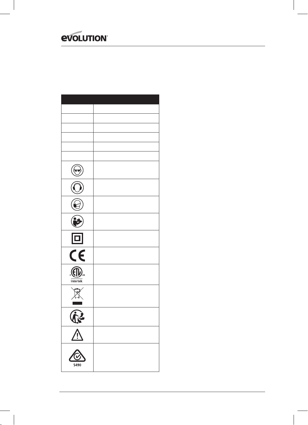
36
www.evolutionpowertools.com
Hinweis: Manche oder alle der folgenden
Symbole können in der Betriebsanleitung oder
auf dem Produkt abgebildet sein.
(1.8)
Symbol Beschreibung
V
Volt
A
Ampere
Hz
Hertz
Min-1 / UpM
Drehzahl
~
Wechselstrom
n
o
Leerlaufdrehzahl
Schutzbrille tragen
Gehörschutz tragen
Staubmaske tragen
Anleitung lesen
Doppelt isoliert
CE-Zertifizierung
ETL-Zertifizierung
Entsorgung als Elektro- &
Elektronikschrott
Triman - Restmüllabfuhr
& Recycling
Warnung
(RCM) Regulatory Compliance Mark
für elektrische und
elektronische Geräte. Australische/
neuseeländische Norm
(1.9) BESTIMMUNGSGEMÄSSER
GEBRAUCH DIESES
ELEKTROWERKZEUGS
WARNUNG: Dieses Produkt ist eine von Hand
betriebene Kreissäge und wurde für den
Einsatz mit speziellen Evolution-Sägeblättern
entwickelt. Verwenden Sie ausschließlich für
den Gebrauch mit dieser Maschine entwickeltes
und/oder ausdrücklich von Evolution Power
Tools Ltd empfohlenes Zubehör.
Mit geeignetem Sägeblatt kann diese Maschine
zum Schneiden der folgenden Materialien
verwendet werden:
Baustahl, Aluminium, Holz
Hinweis: Das Sägen von galvanisch
behandeltem Stahl kann die Lebensdauer des
Blatts verkürzen.
(1.10) UNZULÄSSIGER GEBRAUCH
DIESES ELEKTROWERKZEUGS
WARNUNG: Dieses Produkt ist eine von
Hand betriebene Kreissäge und darf nur
bestimmungsgemäß verwendet werden. Es
dürfen keinerlei Modifikationen vorgenommen
werden. Weiterhin darf die Maschine nicht mit
anderer Ausrüstung oder anderem Zubehör als
dem in dieser Betriebsanleitung erwähntem in
Betrieb genommen werden.
(1.11) WARNUNG: Diese Maschine ist nicht
bestimmt für die Benutzung durch Personen
(einschließlich Kindern) mit eingeschränkten
körperlichen, sensorischen bzw. geistigen
Fähigkeiten, mangelnder Erfahrung bzw.
fehlendem Wissen. Kinder müssen beaufsichtigt
werden, um sicherzustellen, dass sie keinen
Zugang zu der Maschine haben und nicht mit
ihr spielen dürfen.
(1.12) ELEKTRISCHE SICHERHEIT
Diese Maschine ist ausgestattet mit den auf
dem Zielmarkt jeweils verwendeten Stecker
und Anschlusskabel. Bei Beschädigung des
Anschlusskabels ist dieses durch ein vom
Hersteller oder dessen Händler zur Verfügung
gestelltes Kabel zu ersetzen.
(1.13) VERWENDUNG IM FREIEN
WARNUNG: Zu Ihrer eigenen Sicherheit sollte
diese Maschine bei Verwendung im Freien
nicht Regen ausgesetzt und nicht in einer
feuchten Umgebung eingesetzt werden.
Platzieren Sie die Maschine nicht auf feuchtem
Untergrund. Wenn verfügbar, arbeiten Sie auf

37
www.evolutionpowertools.com
DE
einer sauberen, trockenen Fläche. Verwenden
Sie für zusätzlichen Schutz eine Fehlerstrom-
Schutzeinrichtung (R.C.D.), die bei Leckstrom
von über 30 mA über einen Zeitraum von 30
ms die Stromzufuhr unterbricht. Überprüfen Sie
vor Verwendung der Maschine jedes Mal die
Fehlerstrom-Schutzeinrichtung (R.C.D.).
Ist ein Verlängerungskabel notwendig, muss
dieses für den Gebrauch im Freien geeignet
und entsprechend gekennzeichnet sein.
Folgen Sie den Anweisungen des Herstellers bei
Verwendung mit einem Verlängerungskabel.
(2.1) ALLGEMEINE
SICHERHEITSHINWEISE FÜR
ELEKTROWERKZEUGE
(Diese Allgemeinen Sicherheitsanweisungen
für Elektrowerkzeuge entsprechen
EN 62841-1: 2015).
WARNUNG Lesen Sie alle Sicherheitshinweise,
Anweisungen, Bebilderungen und
technischen Daten, mit denen dieses
Elektrowerkzeug versehen ist. Versäumnisse
bei der Einhaltung der nachfolgenden
Anweisungen können elektrischen Schlag,
Brand und/oder schwere Verletzungen
verursachen.
Bewahren Sie alle Sicherheitshinweise und
Anweisungen für die Zukunft auf.
Der in den Sicherheitshinweisen verwendete
Begriff „Elektrowerkzeug“ bezieht sich auf
netzbetriebene Elektrowerkzeuge (mit Netzleitung)
oder auf akkubetriebene Elektrowerkzeuge (ohne
Netzleitung).
(2.2) 1) Allgemeine Sicherheitswarnungen
zum Elektrowerkzeug [Sicherheit am
Arbeitsplatz]
a) Halten Sie den Arbeitsbereich sauber und
sorgen Sie für eine gute Beleuchtung.
Zugestellte oder dunkle Bereiche begünstigen
Unfälle.
b) Verwenden Sie das Elektrowerkzeug
nicht in explosionsgefährdeten Bereichen
wie z.B. bei Vorhandensein von brennbarer
Flüssigkeit, Gasen oder Staub. -
Elektrowerkzeuge erzeugen Funken, die
Staub oder Gase entzünden können.
c) Halten Sie Kinder und Unbeteiligte
während des Betriebs vom Elektrowerkzeug
fern. Ablenkungen können dazu führen, dass
Sie die Kontrolle über das Werkzeug verlieren.
(2.3) 2) Allgemeine Sicherheitswarnungen
zum Elektrowerkzeug [Elektrische
Sicherheit]
a) Der Stecker des Elektrowerkzeugs muss
zur Steckdose passen. Den Stecker niemals
modifizieren. Verwenden Sie keine Adapter
mit geerdeten Elektrowerkzeugen. Nicht
modifizierte Stecker und dazu passende
Steckdosen verringern das Risiko eines
Stromschlags.
b) Vermeiden Sie den Kontakt mit geerdeten
Oberflächen wie z.B. Rohren, Heizungen,
Herden oder Kühlschränken. Das Risiko eines
Stromschlags steigt, wenn Ihr Körper geerdet ist.
c) Setzen Sie Elektrowerkzeuge nie Regen
oder nassen Bedingungen aus. Wasser, das in
ein Elektrowerkzeug eindringt, erhöht das Risiko
eines Stromschlags.
d) Verwenden Sie das Kabel nicht
unzweckmäßig. Verwenden Sie das
Kabel nicht, um das Elektrowerkzeug zu
transportieren oder zu ziehen oder den
Stecker herauszuziehen. Halten Sie das
Netzkabel fern von Hitze, Öl, scharfen
Kanten oder sich bewegenden Geräteteilen.
Beschädigte oder verwickelte Kabel erhöhen
das Risiko eines Stromschlags.
e) Verwenden Sie ein geeignetes
Verlängerungskabel, wenn Sie das
Elektrowerkzeug im Freien betreiben. Die
Verwendung eines für den Gebrauch im Freien
vorgesehenen Verlängerungskabels vermindert
das Risiko eines Stromschlags.
f) Ist die Verwendung des Elektrowerkzeugs
in feuchter Umgebung unumgänglich,
verwenden Sie eine Fehlerstrom-
Schutzeinrichtung (R.C.D.).
Die Verwendung einer Fehlerstrom-
Schutzeinrichtung verringert das Risiko
eines Stromschlags.
Hinweis: Das Gerät ist nur zur Verwendung
in Anwesen vorgesehen, die eine
Dauerstrombelastbarkeit des Netzes von
≥ 100A je Phase haben und von einem
Verteilernetz mit einer Netzspannung von 230V
versorgt werden. Wenn nötig bitte Rücksprache
mit dem Elektrizitätsversorgungsunternehmen
halten, um sicherzustellen, dass die
Dauerstrombelastbarkeit des Neztes am
Anschlusspunkt mit dem öffentlichen Netz für
den Anschluss des Gerätes ausreicht.

38
www.evolutionpowertools.com
(2.4) 3) Allgemeine Sicherheitswarnungen
zum Elektrowerkzeug [Persönliche
Sicherheit].
a) Seien Sie beim Betrieb des
Elektrowerkzeugs immer aufmerksam
und verantwortungsbewusst. Verwenden
Sie das Elektrowerkzeug nicht bei
Müdigkeit oder unter Einfluss von Drogen,
Alkohol oder Medikamenten. Eine kurze
Unachtsamkeit während der Verwendung
dieses Elektrowerkzeugs kann zu schweren
körperlichen Verletzungen führen.
b) Verwenden Sie persönliche
Schutzausrüstung. Tragen Sie stets
eine Schutzbrille. Das Tragen von
Schutzausrüstung wie Staubmaske,
rutschfesten Sicherheitsschuhen, Schutzhelm
oder Gehörschutz verringert das Risiko von
Verletzungen.
c) Vermeiden Sie unbeabsichtigte
Inbetriebnahme. Vergewissern Sie sich, dass
das Werkzeug ausgeschaltet ist, bevor Sie es
an die Stromquelle und/oder an die Batterie
anschließen, anheben oder transportieren.
Das Tragen von Elektrowerkzeugen mit dem
Finger am Schalter oder die Aktivierung der
Stromversorgung einer Maschine, deren
Schalter in der Stellung „ON“ (An) steht, kann zu
Unfällen führen.
d) Entfernen Sie alle Einstell- und sonstigen
Schlüssel, bevor Sie das Elektrowerkzeug
einschalten. Schraubenschlüssel oder andere
Schlüssel, die in sich bewegenden Teilen des
Elektrowerkzeugs stecken, können körperliche
Verletzungen verursachen.
e) Lehnen Sie sich nicht zu weit vor. Achten
Sie stets auf guten Stand bzw. gute Balance.
Dies sorgt für eine bessere Kontrolle des
Elektrowerkzeugs in unerwarteten Situationen.
f) Tragen Sie angemessene Kleidung. Tragen
Sie keine weite Kleidung oder Schmuck. Halten
Sie Haare, Kleidung und Handschuhe fern
von sich bewegenden Teilen. Weite Kleidung,
Schmuck oder langes Haar kann sich in
bewegenden Teilen verfangen.
g) Falls Vorrichtungen zum Absaugen
und Sammeln von Staub vorhanden sind,
schließen Sie diese an und verwenden Sie
sie ordnungsgemäß. Die Verwendung eines
Staubabscheiders vermindert durch Staub
verursachte Gefahren.
h) Eine im Laufe der Zeit gewonnene
Vertrautheit mit dem Werkzeuggebrauch
sollte nicht zu Sorglosigkeit und dem
Ignorieren von Sicherheitshinweisen
führen. Eine Unachtsamkeit kann zu schweren
Verletzungen in kürzester Zeit führen.
(2.5) 4) Allgemeine Sicherheitswarnungen
zum Elektrowerkzeug [Gebrauch und
Instandhaltung].
a) Wenden Sie keine Gewalt an.
Verwenden Sie ein für Ihre Zwecke
geeignetes Elektrowerkzeug. Das passende
Elektrowerkzeug erledigt die Arbeit besser und
sicherer in angemessenem Tempo.
b) Verwenden Sie das Elektrowerkzeug
nicht, wenn der Schalter nicht ein- oder
ausschaltet. Jedes Elektrowerkzeug, dessen
An-/Ausschalter nicht funktioniert, stellt eine
Gefahr dar und muss repariert werden.
c) Trennen Sie das Elektrowerkzeug von der
Netzquelle und/oder der Batterie, bevor
Sie Änderungen vornehmen, Zubehör
auswechseln oder das Elektrowerkzeug
lagern. Derartige vorbeugende Maßnahmen
verringern das Risiko, dass das Elektrowerkzeug
unbeabsichtigt startet.
d) Bewahren Sie unbenutzte Geräte
außerhalb der Reichweite von Kindern auf
und lassen Sie Personen, die mit dem Gerät
nicht vertraut sind oder diese Anweisungen
nicht gelesen haben, das Gerät nicht
benutzen. Das Gerät kann gefährlich sein, wenn
es von unerfahrenen Personen benutzt wird.
e) Halten Sie Elektrowerkzeuge instand.
Stellen Sie sicher, dass sich alle beweglichen
Teile in der richtigen Position befinden, keine
Teile gebrochen sind oder sonstige Fehler
vorliegen, um den reibungslosen Betrieb
des Geräts sicherzustellen. Sollten Schäden
vorliegen, lassen Sie das Elektrowerkzeug
vor Gebrauch reparieren. Viele Unfälle
werden von schlecht instand gehaltenen
Elektrowerkzeugen verursacht.
f) Halten Sie Schneidewerkzeuge scharf
und sauber. Angemessen gepflegtes
Schneidewerkzeug mit scharfen Sägeblättern
läuft geschmeidiger und ist leichter zu kontrollieren.
g) Verwenden Sie das Elektrowerkzeug, Zubehör
und Werkzeugteile usw. in Übereinstimmung
mit diesen Anweisungen unter Berücksichtigung
der Arbeitsumstände und der auszuführenden
Arbeit. Die unzweckmäßige Verwendung des
Elektrowerkzeugs kann zu Gefahr führen.
h) Halten Sie Handgriffe und Greifflächen
trocken, sauber und frei von Öl und Fett.
Rutschige Griffe und Greifflächen verhindern die

39
www.evolutionpowertools.com
DE
sichere Handhabung und Kontrolle des Werkzeugs
in unerwarteten Situationen.
(2.6) 5) Allgemeine Sicherheitswarnungen für
das Elektrowerkzeug [Wartung]
Lassen Sie Ihr Elektrowerkzeug von
qualifiziertem Fachpersonal und nur
mit identischen Ersatzteilen reparieren.
Dadurch wird die fortwährende Sicherheit des
Elektrowerkzeugs gewährleistet.
(2.7) GESUNDHEITSHINWEISE
WARNUNG: Bei Arbeiten mit dieser Maschine
können Staubpartikel entstehen. Je nachdem, mit
welchem Material Sie arbeiten, kann dieser Staub
besonders schädlich sein. Suchen Sie professionelle
Hilfe auf, wenn Sie vermuten, dass die Farbe auf
dem Material, das Sie schneiden wollen, Blei enthält.
Auf Blei basierte Farben sind von professionellen
Fachkräften zu entfernen. Von Selbstversuchen ist
abzuraten.
Hat sich der Staub auf Oberflächen abgesetzt,
kann Hand-Mund-Kontakt zur Aufnahme von
Blei führen. Schon geringe Mengen an Blei
können unwiderrufliche Schäden an Hirn und
Nervensystem verursachen. Junge und ungeborene
Kinder sind besonders gefährdet.
Ziehen Sie die Risiken verbunden mit dem Material,
mit dem Sie arbeiten, in Erwägung und verringern
Sie das Risiko, sich dem auszusetzen.
Da manche Materialien potenziell
gesundheitsschädlichen Staub produzieren,
empfehlen wir während des Betriebs der Maschine
die Verwendung von zugelassenen Schutzmasken
mit austauschbaren Filtern.
Sie sollten stets:
• in gut belüfteten Bereichen arbeiten.
• geprüfte Schutzausrüstung tragen, z.B.
Staubmasken für die Filterung mikroskopisch
kleiner Partikel.
(2.8) WARNUNG: Bei der Arbeit mit
Elektrowerkzeugen können Objekte in Richtung
Ihrer Augen geschleudert werden. Dies
kann zu schweren Verletzungen der Augen
führen. Tragen Sie vor Inbetriebnahme des
Elektrowerkzeugs immer eine Sicherheitsbrille
oder eine Schutzbrille mit seitlichem Schutz
oder wenn notwendig einen Gesichtsschutz.
SICHERHEITSANWEISUNGEN FÜR ALLE
SÄGEN [Schnittverfahren]
a) GEFAHR: Kommen Sie mit Ihren Händen
nicht in den Sägebereich und an das Sägeblatt.
Halten Sie mit Ihrer zweiten Hand den
Zusatzgriff oder das Motorgehäuse. Wenn
beide Hände die Säge halten, können diese
vom Sägeblatt nicht verletzt werden.
b) Greifen Sie nicht unter das Werkstück. Die
Schutzhaube kann Sie unter dem Werkstück
nicht vor dem Sägeblatt schützen.
c) Passen Sie die Schnitttiefe an die Dicke des
Werkstücks an. Es sollte weniger als eine volle
Zahnhöhe unter dem Werkstück sichtbar sein.
d) Halten Sie das zu sägende Werkstück
niemals in der Hand oder über dem Bein fest.
Sichern Sie das Werkstück an einer stabilen
Aufnahme. Es ist wichtig, das Werkstück gut zu
befestigen, um die Gefahr von Körperkontakt,
Klemmen des Sägeblattes oder Verlust der
Kontrolle zu minimieren.
e) Halten Sie das Elektrowerkzeug an den
isolierten Griffflächen, wenn Sie Arbeiten
ausführen, bei denen das Einsatzwerkzeug
verborgene Stromleitungen oder die eigene
Anschlussleitung treffen kann. Kontakt mit
einer spannungsführenden Leitung setzt auch
die Metallteile des Elektrowerkzeugs unter
Spannung und führt zu einem elektrischen
Schlag.
f) Verwenden Sie beim Längsschneiden
immer einen Anschlag oder eine gerade
Kantenführung. Dies verbessert die
Schnittgenauigkeit und verringert die
Möglichkeit, dass das Sägeblatt klemmt.
g) Verwenden Sie immer Sägeblätter in
der richtigen Größe und mit passender
Aufnahmebohrung (z. B. rautenförmig
oder rund). Sägeblätter, die nicht zu den
Montageteilen der Säge passen, laufen unrund
und führen zum Verlust der Kontrolle.
h) Verwenden Sie niemals beschädigte oder
falsche Sägeblatt-Unterlegscheiben oder
-Schrauben. Die Sägeblatt-Unterlegscheiben
und -Schrauben wurden speziell für Ihre
Säge konstruiert, für optimale Leistung und
Betriebssicherheit.
(3.2)
Weitere Sicherheitshinweise für alle Sägen
Rückschlag – Ursachen und entsprechende
Sicherheitshinweise
– Ein Rückschlag ist die
plötzliche Reaktion infolge eines hakenden,
klemmenden oder falsch ausgerichteten
Sägeblattes, die dazu führt, dass eine
unkontrollierte Säge abhebt und sich aus
dem Werkstück heraus in Richtung des
Bedienperson bewegt.
– Wenn sich das Sägeblatt in dem sich
schließenden Sägespalt verhakt oder
verklemmt, blockiert es, und die Motorkraft

40
www.evolutionpowertools.com
schlägt die Säge in Richtung der Bedienperson
zurück.
– Wird das Sägeblatt im Sägeschnitt verdreht
oder falsch ausgerichtet, können sich die
Zähne der hinteren Sägeblattkante in der
Holz-Oberfläche verhaken, wodurch sich das
Sägeblatt aus dem Sägespalt heraus bewegt
und die Säge in Richtung der Bedienperson
zurückspringt.
Ein Rückschlag ist die Folge eines falschen
oder fehlerhaften Gebrauchs der Säge. Er kann
durch geeignete Vorsichtsmaßnahmen, wie
nachfolgend beschrieben, verhindert werden.
a) Halten Sie die Säge mit beiden Händen
fest und bringen Sie Ihre Arme in eine
Stellung, in der Sie die Rückschlagkräfte
abfangen können. Halten Sie sich
immer seitlich des Sägeblattes, nie das
Sägeblatt in eine Linie mit Ihrem Körper
bringen. Bei einem Rückschlag kann die
Kreissäge rückwärts springen, jedoch
kann die Bedienperson durch geeignete
Vorsichtsmaßnahmen die Rückschlagkräfte
beherrschen.
b) Falls das Sägeblatt verklemmt oder Sie die
Arbeit unterbrechen, schalten Sie die Säge
aus und halten Sie sie im Werkstoff ruhig,
bis das Sägeblatt zum Stillstand gekommen
ist. Versuchen Sie nie, die Säge aus dem
Werkstück zu entfernen oder sie rückwärts zu
ziehen, solange das Sägeblatt sich bewegt,
sonst kann ein Rückschlag erfolgen. Ermitteln
und beheben Sie die Ursache für das
Verklemmen des Sägeblattes.
c) Wenn Sie eine Säge, die im Werkstück steckt,
wieder starten wollen, zentrieren Sie das
Sägeblatt im Sägespalt und überprüfen Sie,
ob die Sägezähne nicht im Werkstück verhakt
sind. Verhakt das Sägeblatt, kann es sich aus
dem Werkstück heraus bewegen oder einen
Rückschlag verursachen, wenn die Säge
erneut gestartet wird.
d) Stützen Sie große Platten ab, um das Risiko
eines Rückschlags durch ein klemmendes
Sägeblatt zu vermindern. Große Platten
können sich unter ihrem Eigengewicht
durchbiegen. Platten müssen auf beiden
Seiten abgestützt werden, und zwar sowohl
in der Nähe des Sägespalts als auch an der
Kante.
e) Verwenden Sie keine stumpfen oder
beschädigten Sägeblätter. Sägeblätter
mit stumpfen oder falsch ausgerichteten
Zähnen verursachen durch einen zu engen
Sägespalt eine erhöhte Reibung, Klemmen
des Sägeblattes und Rückschlag.
f) Ziehen Sie vor dem Sägen die
Schnitttiefen- und Schnittwinkeleinstellungen
fest. Wenn sich während des Sägens die
Einstellungen verändern, kann sich das
Sägeblatt verklemmen und ein Rückschlag
auftreten.
g) Seien Sie besonders vorsichtig beim Sägen
in bestehende Wände oder andere nicht
einsehbare Bereiche. Das eintauchende
Sägeblatt kann beim Sägen in verborgene
Objekte blockieren und einen Rückschlag
verursachen.
FUNKTIONSWEISE DES UNTEREN
SCHUTZES
a) Überprüfen Sie vor jeder Benutzung, ob
die untere Schutzhaube einwandfrei schließt.
Verwenden Sie die Säge nicht, wenn die untere
Schutzhaube nicht frei beweglich ist und sich
nicht sofort schließt. Klemmen oder binden Sie
die untere Schutzhaube niemals in geöffneter
Position fest. Sollte die Säge unbeabsichtigt
zu Boden fallen, kann die untere Schutzhaube
verbogen werden. Öffnen Sie die Schutzhaube
mit dem Rückziehhebel und stellen Sie
sicher, dass sie sich frei bewegt und bei allen
Schnittwinkeln und -tiefen weder Sägeblatt
noch andere Teile berührt.
b) Überprüfen Sie die Funktion der Feder
für die untere Schutzhaube. Lassen Sie die
Säge vor dem Gebrauch warten, wenn untere
Schutzhaube und Feder nicht einwandfrei
arbeiten. Beschädigte Teile, klebrige
Ablagerungen oder Anhäufungen von Spänen
lassen die untere Schutzhaube verzögert
arbeiten.
c) Öffnen Sie die untere Schutzhaube von
Hand nur bei besonderen Schnitten, wie z. B.
„Tauch- und Winkelschnitten“. Öffnen Sie die
untere Schutzhaube mit dem Rückziehhebel
und lassen Sie diesen los, sobald das Sägeblatt
in das Werkstück eintaucht. Bei allen anderen
Sägearbeiten soll die untere Schutzhaube
automatisch arbeiten.
d) Legen Sie die Säge nicht auf der Werkbank
oder dem Boden ab, ohne dass die untere
Schutzhaube das Sägeblatt bedeckt. Ein
ungeschütztes, nachlaufendes Sägeblatt
bewegt die Säge entgegen der Schnittrichtung
und sägt, was ihm im Weg ist. Beachten Sie
dabei die Nachlaufzeit des Sägeblatts.
ZUSÄTZLICHE
SICHERHEITSHINWEISE

41
www.evolutionpowertools.com
DE
FÜR KREISSÄGEN
a) Verwenden Sie keine Sägeblätter aus
Schnellarbeitsstahl.
b) Überprüfen Sie die Maschine und das
Sägeblatt vor jeder Inbetriebnahme.
Verwenden Sie keine verformten,
rissigen, abgenutzten oder anderweitig
beschädigten Sägeblätter.
c) Verwenden Sie die Säge niemals ohne das
Original-Schutzsystem. Stellen Sie
in offener Stellung niemals den beweglichen
Schutz fest. Stellen Sie sicher, dass der Schutz
frei beweglich ist.
d) Verwenden Sie nur Sägeblätter, die mit
denin dieser Betriebsanleitung aufgeführten
Eigenschaften übereinstimmen. Vergleichen
Sie vor Verwendung von Zubehör stets die
maximale Drehzahl des Zubehörs mit der
der Maschine.
e) Verwenden Sie keine Schleifscheiben.
f) Verwenden Sie nur Blattdurchmesser
entsprechend den Markierungen.
-Suchen Sie das richtige Sägeblatt entsprechend
dem zu sägenden Werkstoff aus.
-Verwenden Sie nur Sägeblätter mit einer
Drehzahl-Kennzeichnung, die der auf dem
Elektrowerkzeug angegebenen Drehzahl
entspricht oder höher ist.
-Verwenden Sie nur vom Hersteller festgelegte
Sägeblätter, die, falls sie zum Schneiden von
Holz oder ähnlichen Werkstoffen vorgesehen
sind, EN 847-1 entsprechen.
-Tragen Sie beim Gebrauch des Gerätes eine
Staubmaske.
-Wenn die Netzanschlussleitung dieses Gerätes
beschädigt wird, muss sie durch eine besondere
Anschlussleitung ersetzt werden, die vom
Hersteller oder seinem Kundendienst erhältlich ist.
(3.4) WARNUNG: Sollten Teile fehlen, verwenden
Sie die Maschine nicht, bis die fehlenden Teile
ersetzt wurden. Das Nichtbefolgen kann zu
schweren körperlichen Verletzungen führen.
(4.1) ERSTE SCHRITTE – AUSPACKEN
Vorsicht: Diese Verpackung enthält scharfe
Gegenstände. Lassen Sie beim Auspacken
Vorsicht walten. Entnehmen Sie die Maschine
sowie das im Lieferumfang enthaltene Zubehör
der Verpackung. Stellen Sie sicher, dass die
Maschine in ordnungsgemäßem Zustand ist,
und vergewissern Sie sich, dass alle in dieser
Betriebsanleitung aufgelisteten Zubehörteile
enthalten sind. Stellen Sie ebenfalls sicher, dass
alle Zubehörteile vollständig sind.
Fehlen Teile, geben Sie die Maschine zusammen
mit dem Zubehör in Originalverpackung beim
Einzelhändler ab.
Entsorgen Sie die Verpackung nicht;
bewahren Sie sie während der Garantiefrist
sicher auf. Entsorgen Sie die Verpackung
umweltfreundlich. Recyceln Sie sie nach
Möglichkeit.
Lassen Sie niemals Kinder mit leeren
Plastiktüten spielen, es besteht
Erstickungsgefahr.
(4.3) Evolution
Bedienungsanleitungen
Evolution Power Tools stellt für jedes Produkt
eine Bedienungsanleitung zur Verfügung.
Jedes Handbuch wurde sorgfältig konzipiert
und entwickelt, um leicht zugängliche
und nützliche Informationen zur sicheren
Verwendung, Pflege und Wartung des Produkts
bereitzustellen. Die Nutzung der Informationen
aus diesem Handbuch ermöglicht dem Bediener
die vollständige und sichere Ausschöpfung des
Potenzials der Maschine.
Evolution verfolgt eine Politik der
kontinuierlichen Produktentwicklung. Das
kann gelegentlich zur Folge haben, dass die
neuesten Verbesserungen oder Erweiterungen,
die in ein bestimmtes Produkt eingeflossen
sind, in seltenen Fällen nicht vollständig in ein
Handbuch übernommen wurden. Upgrades
oder Verbesserungen eines Produkts können
als Folge von technologischen Fortschritten
oder Änderungen des rechtlichen Rahmens des
empfangenden Landes usw. auftreten.
Wenn Sie sich zu einem Aspekt der Nutzung,
Pflege oder Wartung eines Produkts nicht
sicher sind, kontaktieren Sie die entsprechende
Website von Evolution oder die Hotline, wo Sie
die aktuellsten Informationen und zusätzliche
Tipps erhalten.

42
www.evolutionpowertools.com
USA
1. AUSWURFÖFFNUNG FÜR SCHNITTMATERIAL
2. DAUMEN-HEBEL
3. MEHRZWECK-TCT-SÄGEBLATT
4. UNTERER SÄGEBLATTSCHUTZ
5. PARALLELE KANTENFÜHRUNG
6. ERGONOMISCHER VORDERER GRIFF
7. KOHLEBÜRSTEN
8. 8 MM SECHSKANTSCHLÜSSEL
(SÄGEBLATTWECHSEL)
9. VERRIEGELUNGSHEBEL FÜR EINSTELLUNG
DER SCHNITTTIEFE
10. TIEFENSKALA
11. HINTERER HANDGRIFF AN-/AUS-SCHALTER
12. OBERER SÄGEBLATTSCHUTZ
13. FEINGESTANZTE BODENPLATTE
14. SCHRÄGEINSTELLUNG DAUMEN-HEBEL
15. WINKELMESSER
16. DORNVERRIEGELUNGSKNOPF
17. LED-LICHT
18. ADAPTER FÜR ENTSTAUBUNGSANSCHLUSS
19. 25/32 Zoll INNERER SÄGEBLATTFLANSCH
20. 5/8 Zoll INNERER SÄGEBLATTFLANSCH
13
15
17
18
19
20
4
14
5
1
3
8
9
10
11
6
7
2
16
12
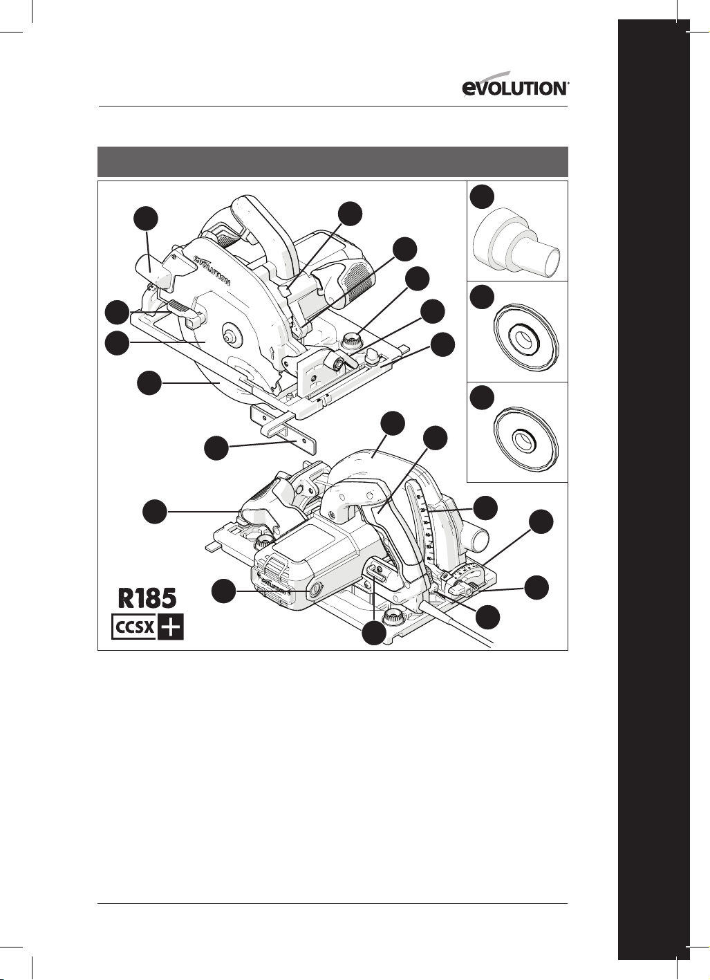
43
www.evolutionpowertools.com
DE
USA
1. AUSWURFÖFFNUNG FÜR SCHNITTMATERIAL
2. DAUMEN-HEBEL
3. MEHRZWECK-TCT-SÄGEBLATT
4. UNTERER SÄGEBLATTSCHUTZ
5. PARALLELE KANTENFÜHRUNG
6. ERGONOMISCHER VORDERER GRIFF
7. KOHLEBÜRSTEN
8. 8 MM SECHSKANTSCHLÜSSEL
(SÄGEBLATTWECHSEL)
9. VERRIEGELUNGSHEBEL FÜR EINSTELLUNG
DER SCHNITTTIEFE
10. TIEFENSKALA
11. HINTERER HANDGRIFF AN-/AUS-SCHALTER
12. OBERER SÄGEBLATTSCHUTZ
13. FEINGESTANZTE MIT FÜHRUNGSSCHIENEN
KOMPATIBLE BODENPLATTE
14. DAUMEN-HEBEL
15. HINTERER WINKELMESSER
16. DORNVERRIEGELUNGSKNOPF
17. LED-LICHT
18. ADAPTER FÜR ENTSTAUBUNGSANSCHLUSS
19. 25/32 Zoll INNERER SÄGEBLATTFLANSCH
20. 5/8 Zoll INNERER SÄGEBLATTFLANSCH
21. DREHKNÖPFE ZUR SCHIENENEINSTELLUNG
22. HINTERE RÄNDELSCHRAUBE
13
21
15
17
18
19
20
4
14
5
1
3
8
9
10
22
11
6
7
2
16
12

44
www.evolutionpowertools.com
13
15
4
14
5
1
3
8
9
10
11
6
7
2
16
12
1. AUSWURFÖFFNUNG FÜR
SCHNITTMATERIAL
2. DAUMEN-HEBEL
3. MEHRZWECK-TCT-SÄGEBLATT
4. UNTERER SÄGEBLATTSCHUTZ
5. PARALLELE KANTENFÜHRUNG
6. ERGONOMISCHER VORDERER GRIFF
7. KOHLEBÜRSTEN
8. 8 MM SECHSKANTSCHLÜSSEL
(SÄGEBLATTWECHSEL)
9. VERRIEGELUNGSHEBEL FÜR EINSTELLUNG
DER SCHNITTTIEFE
10. TIEFENSKALA
11. HINTERER HANDGRIFF MIT
SICHERHEITS-AN-/AUS-SCHALTER
12. OBERER SÄGEBLATTSCHUTZ
13. FEINGESTANZTE BODENPLATTE
14. DAUMEN-HEBEL
15. WINKELMESSER
16. DORNVERRIEGELUNGSKNOPF
GB / EU / AUS

45
www.evolutionpowertools.com
DE
1. AUSWURFÖFFNUNG FÜR
SCHNITTMATERIAL
2. DAUMEN-HEBEL
3. MEHRZWECK-TCT-SÄGEBLATT
4. UNTERER SÄGEBLATTSCHUTZ
5. PARALLELE KANTENFÜHRUNG
6. ERGONOMISCHER VORDERER GRIFF
7. KOHLEBÜRSTEN
8. 8 MM SECHSKANTSCHLÜSSEL
(SÄGEBLATTWECHSEL)
9. VERRIEGELUNGSHEBEL FÜR EINSTELLUNG
DER SCHNITTTIEFE
10. TIEFENSKALA
11. HINTERER HANDGRIFF MIT
SICHERHEITS-AN-/AUS-SCHALTER
12. OBERER SÄGEBLATTSCHUTZ
13. FEINGESTANZTE BODENPLATTE
14. DAUMEN-HEBEL
15. WINKELMESSER
16. DORNVERRIEGELUNGSKNOPF
17. ADAPTER FÜR ENTSTAUBUNGSANSCHLUSS
GB / EU
13
15
17
4
14
5
1
3
8
9
10
11
6
7
2
16
12
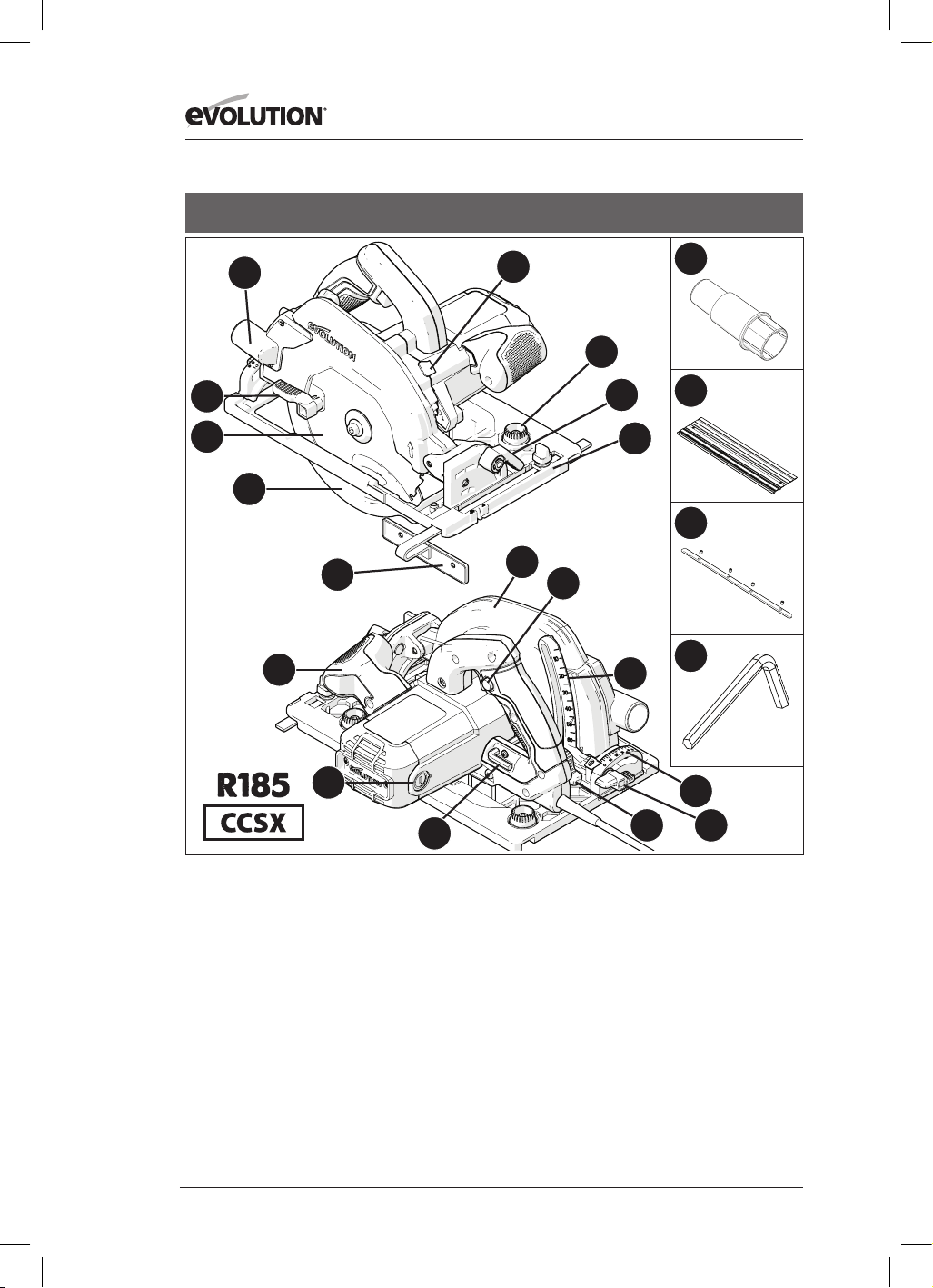
46
www.evolutionpowertools.com
13
18
15
17
20
21
22
4
14
5
1
3
8
9
10
19
11
6
7
2
16
12
1. AUSWURFÖFFNUNG FÜR SCHNITTMATERIAL
2. DAUMEN-HEBEL
3. MEHRZWECK-TCT-SÄGEBLATT
4. UNTERER SÄGEBLATTSCHUTZ
5. PARALLELE KANTENFÜHRUNG
6. ERGONOMISCHER VORDERER GRIFF
7. KOHLEBÜRSTEN
8. 8 MM SECHSKANTSCHLÜSSEL
(SÄGEBLATTWECHSEL)
9. VERRIEGELUNGSHEBEL FÜR EINSTELLUNG
DER SCHNITTTIEFE
10. TIEFENSKALA
11. HINTERER HANDGRIFF MIT
SICHERHEITS-AN-/AUS-SCHALTER
12. OBERER SÄGEBLATTSCHUTZ
13. FEINGESTANZTE MIT FÜHRUNGSSCHIENEN
KOMPATIBLE BODENPLATTE
14. DAUMEN-HEBEL
15. HINTERER WINKELMESSER
16. DORNVERRIEGELUNGSKNOPF
17. ADAPTER FÜR ENTSTAUBUNGSANSCHLUSS
18. DREHKNÖPFE ZUR SCHIENENEINSTELLUNG
19. HINTERE RÄNDELSCHRAUBE
20. 3x 340 MM-SCHIENE
21. 4x SCHIENENVERBINDUNGSSTANGE
22. 3 MM SECHSKANTSCHLÜSSEL
GB / EU

47
www.evolutionpowertools.com
DE
GB / EU
1. AUSWURFÖFFNUNG FÜR SCHNITTMATERIAL
2. DAUMEN-HEBEL
3. MEHRZWECK-TCT-SÄGEBLATT
4. UNTERER SÄGEBLATTSCHUTZ
5. PARALLELE KANTENFÜHRUNG
6. ERGONOMISCHER VORDERER GRIFF
7. KOHLEBÜRSTEN
8. 8 MM SECHSKANTSCHLÜSSEL
(SÄGEBLATTWECHSEL)
9. VERRIEGELUNGSHEBEL FÜR EINSTELLUNG
DER SCHNITTTIEFE
10. TIEFENSKALA
11. HINTERER HANDGRIFF MIT
SICHERHEITS-AN-/AUS-SCHALTER
12. OBERER SÄGEBLATTSCHUTZ
13. FEINGESTANZTE MIT FÜHRUNGSSCHIENEN
KOMPATIBLE BODENPLATTE
14. DAUMEN-HEBEL
15. HINTERER WINKELMESSER
16. DORNVERRIEGELUNGSKNOPF
17. ADAPTER FÜR ENTSTAUBUNGSANSCHLUSS
18. DREHKNÖPFE ZUR SCHIENENEINSTELLUNG
19. HINTERE RÄNDELSCHRAUBE
13
18
15
17
4
14
5
1
3
8
9
10
19
11
6
7
2
16
12

48
www.evolutionpowertools.com
Abb. 3Abb. 2
Abb. 4
Abb. 1
Abb. 8
Abb. 6Abb. 5
Abb. 9
Abb. 10
Abb. 7a Abb. 7b Abb. 7c
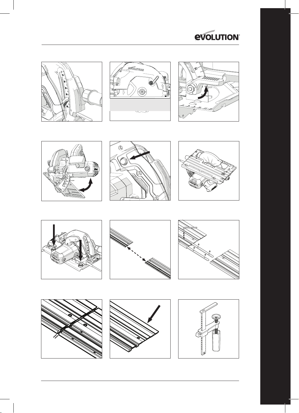
49
www.evolutionpowertools.com
DE
Abb. 11
Abb. 12
Abb. 13
Abb. 14
Abb. 15
Abb. 16
Abb. 17 Abb. 18
Abb. 21Abb. 20
Abb. 19
Abb. 22
1-2 mm
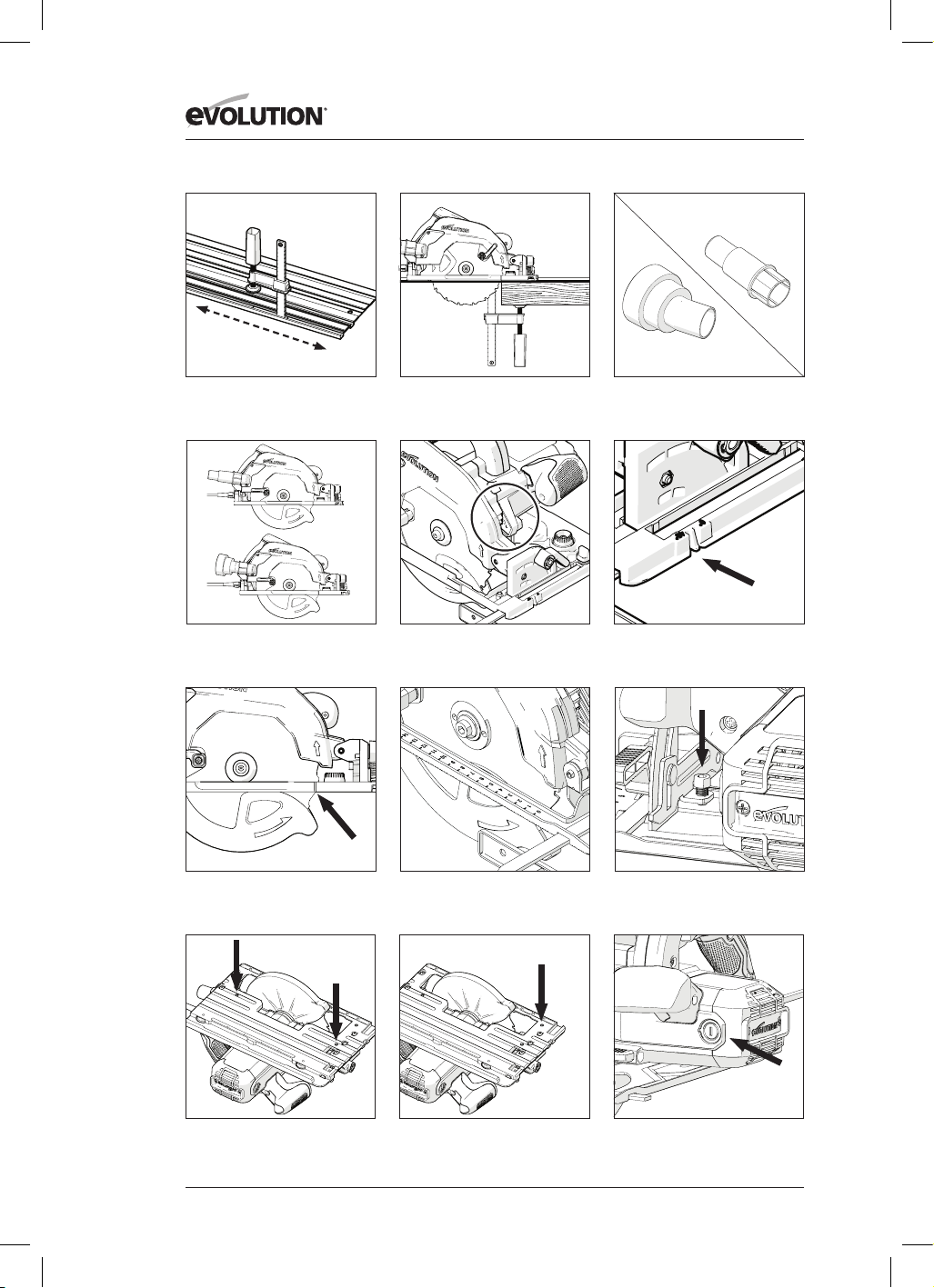
50
www.evolutionpowertools.com
Abb. 27Abb. 26
Abb. 25
Abb. 30 Abb. 31
Abb. 34
Abb. 24Abb. 23
US-Adapter für
Entstaubungsanschluss
EU-Adapter für
Entstaubungsanschluss
Abb. 28
Abb. 29
Abb. 32 Abb. 33

51
www.evolutionpowertools.com
DE
(10) VORBEREITUNG
WARNUNG: Trennen Sie die Maschine stets von der
Stromversorgung, bevor Sie jegliche Einstellungen
vornehmen.
Hinweis: Diese Maschinen sind mit einem für
das Zielland geeigneten Stromkabel und Stecker
ausgestattet. Modifizieren oder verändern Sie das
Stromkabel nicht.
(10.1) EINSETZEN / ENTFERNEN
EINES SÄGEBLATTS
WARNUNG: Verwenden Sie nur originale
Sägeblätter von Evolution (oder von Evolution
Power Tools anerkannte), die für den Einsatz in
diesen Maschinen konzipiert wurden. Stellen
Sie sicher, dass die maximale Drehzahl des
Sägeblattes mit der Maschine kompatibel ist.
Diese Arbeiten dürfen lediglich bei getrennter
Hauptstromversorgung durchgeführt werden.
Hinweis: Es wird empfohlen, dass der Bediener
bei der Handhabung des Sägeblattes während der
Montage oder beim Austausch des Sägeblattes
Schutzhandschuhe trägt.
• Finden Sie den mitgelieferten
Sechskantschlüssel für den Wechsel der
Sägeblätter, der sich im Aufbewahrungsfach an
der Maschine befindet (an allen Maschinen in
ähnlicher Position). (Abb. 1)
• Platzieren Sie die Säge auf einer ebenen,
sicheren Oberfläche.
Hinweis: Alle Maschinen können vorsichtig auf dem
flachen Ende des Motorgehäuses (Abb. 2) platziert
werden, was Ihnen einfachen Zugriff auf das
Sägeblatt und dessen Befestigungen gewährt.
• Finden Sie den Dornverriegelungsknopf der
Maschine (an allen Maschinen in ähnlicher
Position). Sperren Sie den Dorn der Maschine
durch Betätigen des Dornverriegelungsknopfs.
(Abb. 3).
Hinweis: Ein langsames Rotieren des Sägeblatts mit
der Hand, während der Dornverriegelungsknopf
sanft gedrückt wird, hilft bei der Sperrung des Dorns.
• Lösen und entfernen Sie die
Innensechskantschraube des Dorns, zugehörige
Halterungen und den äußeren Sägeblatt-
Antriebsflansch mit dem Sechskantschlüssel.
(Abb. 4)
Hinweis: Die Innensechskantschraube ist mit einem
Standard-Schraubengewinde ausgestattet.
Drehen Sie die Schraube im Uhrzeigersinn, um sie
anzuziehen. Drehen Sie die Schraube gegen den
Uhrzeigersinn, um sie zu lösen.
• Bewahren Sie den äußeren Sägeblatt-Flansch
und alle zugehörigen Befestigungen sicher auf.
• Drehen Sie den unteren Sägeblattschutz mit
Hilfe des manuellen Daumen-Hebels in den
oberen Sägeblattschutz. (Abb. 5)
• Entfernen Sie das Sägeblatt (falls eingesetzt)
vorsichtig aus der Maschine.
• Reinigen Sie die inneren und äußeren
Sägeblatt-Antriebsflansche sorgfältig.
Hinweis: Der innere Sägeblatt-Flansch kann, falls
gewünscht, an Ort und Stelle belassen werden; er
sollte jedoch überprüft und gründlich gereinigt
werden. Falls er aus der Maschine entfernt wird,
muss er mit derselben Ausrichtung wie zuvor
wieder eingesetzt werden.
• Reinigen Sie das Sägeblatt gründlich im Bereich
der Bohrungen (beide Oberflächen), wo die
Blattflansche das Sägeblatt berühren und
festklemmen.
• Setzen Sie das (neue) Sägeblatt ein.
• Stellen Sie sicher, dass die auf dem Sägeblatt
aufgedruckte Drehrichtung der Richtung
der Pfeile auf dem oberen und unteren
Sägeblattschutz entspricht. (Abb. 6)
• Setzen Sie den äußeren Antriebsflansch, die
Sechskantschraube und die zugehörigen
Befestigungen erneut ein.
Hinweis: Der äußere Antriebsflansch hat eine
speziell bearbeitete Bohrung, die über zwei
gegenüberliegende flache Stellen verfügt. (Abb.
7a) Diese treffen mit zwei komplementären
flachen Stellen, die in den Dornschaft der
Maschine eingearbeitet sind, zusammen.
• Betätigen Sie die Dornsperre erneut und ziehen
Sie die Sechskantschraube des Dorns mit Hilfe
des Sechskantschlüssels sorgfältig fest.
• Lassen Sie den Dornverriegelungsknopf los
• Verwahren Sie den Sechskantschlüssel an
seinem entsprechenden Aufbewahrungsort.
• Überprüfen Sie, ob die Dornsperre vollständig
gelöst ist, indem Sie das Sägeblatt per Hand
drehen.
• Prüfen Sie die Funktion des unteren Schutzes.
Hinweis: Für den nordamerikanischen Markt ist
nur ein zweiseitiger Dornflansch enthalten für
Sägeblätter mit 1-Zoll-Bohrung (Abb. 7b) und
5/8-Zoll-Bohrung (Abb. 7c).

52
www.evolutionpowertools.com
(11) PARALLELE KANTENFÜHRUNG
Eine parallele Kantenführung (Abb. 8) kann
besonders beim Kappschneiden hilfreich sein und
wird bei allen CCS-Maschinen mitgeliefert. Die
Führung kann auf der Vorderseite der Bodenplatte
angebracht werden.
Der Arm der Führung sollte durch die rechteckigen
Schlitze an jeder Seite (vorn) der Pressstahl-
Bodenplatte eingeführt und dann unter die in der
Mitte befindliche Einstellsperrschraube geschoben
werden. (Abb. 9)
Hinweis: Die parallele Kantenführung kann auf
beiden Seiten der Bodenplatte angebracht werden.
WARNUNG: Die Führung darf nur eingesetzt
und eingestellt werden, wenn die Maschine vom
Stromnetz getrennt ist.
Hinweis: Der Arm der parallelen Kantenführung
muss alle rechteckigen Schlitze in der Bodenplatte
durchlaufen.
WARNUNG: Es kann gefährlich sein, die
Kantenführung einzusetzen oder zu verwenden,
wenn der Arm nur durch einen (1) der rechteckigen
Schlitze in der Bodenplatte verläuft.
Passen Sie die Kantenführung so an, dass sie den
erforderlichen Abstand zum Sägeblatt hat und
ziehen Sie die Einstellschraube fest. Überprüfen
Sie, dass die Kantenführung parallel zum Sägeblatt
ausgerichtet ist.
(12) EINSTELLEN DER SCHNITTTIEFE
Hinweis: Die allgemeine Einstellung der
Schnitttiefe erfolgt bei allen CCS-Maschinen mit
Hilfe der gleichen Bauteile und über die gleiche
grundlegende Technik zur Einstellung der Blatttiefe.
• Lösen Sie die Verriegelung für die Einstellung der
Schnitttiefe, indem Sie den Bedienhebel nach
oben ziehen. (Abb. 10)
• Durch die Einstellung / Repositionierung der
Bodenplatte kann die erforderliche Schnitttiefe
erreicht werden (Differenz, um die das Sägeblatt
aus der Bodenplatte herausragt).
Hinweis: Auf dem Tiefenanpassungs-
Quadranten befindet sich eine Tiefenskala
mit einer entsprechenden Indexmarkierung
in dem angrenzenden Bereich des oberen
Sägeblattschutzes der Maschine. (Abb. 11) Mit Hilfe
dieser Funktionen können Einstellungen schnell
vorgenommen werden.
Hinweis: Obwohl die Tiefenskala und
Indexmarkierung sehr hilfreich für schnelle
Tiefeneinstellungen sind, sollte deren Verwendung
stets als Anleitung für die erreichte Einstellung
betrachtet werden.
Wenn eine sehr präzise Schnitttiefe erforderlich ist,
sollte die Einstellung des Sägeblatts mit Hilfe eines
Präzisions-Lineals (nicht im Lieferumfang enthalten)
o. ä. überprüft werden.
• In den meisten Fällen sollte die Schnitttiefe auf
die Dicke des zu schneidenden Materials plus
die halbe Tiefe eines Sägezahns (Spitze des
Sägezahns bis zum breitesten Teil) eingestellt
werden. (Abb.12)
• Schließen Sie die Verriegelung der
Tiefeneinstellung, indem Sie den Bedienhebel
nach unten drücken, um die Maschine in der
gewünschten Position zu sichern.
(13) EINSTELLEN DES
SCHNITTWINKELS (SCHRÄGE)
Die CCSL- und CCSX-Maschinen verfügen über die
Möglichkeit, das Sägeblatt um bis zu 45° nach links
zu kippen. Die CCS-Maschinen verfügen über die
Möglichkeit, das Sägeblatt um bis zu 60° nach links
zu kippen.
Daher sind Schrägschnitte möglich.
Hinweis: Das Sägeblatt befindet sich in vertikaler
Position, wenn der Winkelmesser auf 0° steht.
Hinweis: Auf dem Winkel-Sperr-Quadranten vorn
auf der Bodenplatte befindet sich ein Winkelmesser
(0°-45° oder 0°-60°). Damit können Winkel schnell
eingestellt werden, was aber nur als Richtschnur
dienen sollte.
Wenn ein sehr präziser Schnittwinkel erforderlich
ist, sollte die Einstellung des Sägeblatts mit
Hilfe eines Präzisions-Winkelmessers (nicht im
Lieferumfang enthalten) o. ä. überprüft werden.
• Lösen Sie den Winkel-Sperrmechanismus vorn
an der Maschine, indem Sie den Hebel nach
oben ziehen. (Abb. 13)
• Kippen Sie das Sägeblatt in den gewünschten
Winkel, wie auf der Winkelskala des Quadranten
angegeben. (Abb. 14)
• Ziehen Sie den Winkel-Sperrmechanismus fest,
wenn der gewünschte Winkel erreicht wurde,
indem Sie den Hebel nach unten drücken.
(14) BEDIENUNGSHINWEISE
(ÜBERPRÜFUNGEN VOR DEM BETRIEB)
Hinweis: Da alle Betriebsumgebungen einmalig
und unterschiedlich sind, bietet Evolution Power
Tools die folgende allgemeine Empfehlung

53
www.evolutionpowertools.com
DE
für einen sicheren Betriebsablauf und sichere
Betriebspraktiken zur Berücksichtigung durch den
Betreiber.
Die Hinweise können aber nur unvollständig
sein, da Evolution keinen Einfluss auf die Art der
Werkstatt oder Arbeitsumgebung hat, in denen die
Maschinen benutzt wird.
Wir empfehlen daher, dass der Betreiber Ratschläge
an kompetenter Stelle oder beim Werkstattchef
einholt, wenn er in Bezug auf irgendeinen Aspekt
der Benutzung dieser Maschinen unsicher ist.
Es ist wichtig, dass routinemäßige
Sicherheitsüberprüfungen (jedes Mal) durchgeführt
werden, bevor der Betreiber die Maschine benutzt.
WARNUNG: Diese Sicherheitsüberprüfungen
vor dem Gebrauch sollten durchgeführt
werden, während die Maschine von der
Hauptstromversorgung getrennt ist.
• Überprüfen Sie, ob alle Schutzeinrichtungen
richtig funktionieren und ob alle
Einstellungshebel und -schrauben sicher
festgestellt beziehungsweise festgedreht sind.
• Überprüfen Sie, ob das Sägeblatt gesichert und
korrekt montiert ist. Überprüfen Sie außerdem,
ob das Sägeblatt für das zu schneidende Material
geeignet ist.
• Überprüfen Sie das Stromkabel auf
Unversehrtheit.
• Wenn immer es möglich ist, klemmen Sie
das Werkstück an eine feste Stützstruktur wie
eine Werkbank, einen Sägebock oder etwas
Ähnliches.
• Der Betreiber sollte sich immer der Position und
Führung des Stromkabels bewusst sein.
(15) PSA
• Der Betreiber sollte die relevante PSA
(persönliche Schutzausrüstung) tragen, die für
die anstehende Aufgabe notwendig ist.
Dies schließt möglicherweise Schutzbrillen,
Vollmasken, Staubmasken, Sicherheitsschuhe
etc. mit ein.
Hinweis: Alle Maschinen der CCS-Serie sind mit
einem Gebläse zur Entfernung von Schmutz
entlang der Schnittlinie ausgestattet. Dieses bläst
Luft mittels eines motorenbetriebenen Ventilators
zum Bereich an der Vorderseite des Sägeblatts,
sodass die Schnittlinie relativ schmutzfrei bleibt.
Diese Eigenschaft hilft dem Betreiber, dem
Fortschreiten des Sägeblatts zu folgen, sodass
aufgezeichnete Linien stets sichtbar sind.
WARNUNG: Jeglicher entstehender Staub ist
potenziell gesundheitsschädlich.
Einige Materialien sind besonders schädlich, und
der Betreiber sollte stets eine Staubmaske tragen,
die für das bearbeitete Material geeignet ist.
Der Betreiber sollte sofort professionelle Hilfe
und Beratung ersuchen, wenn er auch nur im
Entferntesten unsicher in Bezug auf die potentielle
Giftigkeit des zu schneidenden Materials ist.
WARNUNG: Diese Maschinen dürfen niemals
benutzt werden, um Asbest oder jegliche
Materialien, die Asbest enthalten oder enthalten
könnten, zu schneiden.
Informieren Sie die zuständigen Behörden und
erfragen Sie weitere Handlungsanweisungen, wenn
Sie eine Kontaminierung mit Asbest vermuten.
(16) AN-/AUS-AUSLÖSESCHALTER
Hinweis: Alle Maschinen, die für den europäischen
und australischen Markt bestimmt sind, sind mit
einem Sicherheitsstartschalter ausgestattet, um die
Sicherheit des Bedieners zu erhöhen. (Abb.15)
Starten des Motors:
• Betätigen Sie mit Ihrem Daumen den seitlich am
Griff gelegenen Sicherheitssperrknopf.
• Drücken Sie den Auslöseschalter herunter.
Stoppen des Motors:
• Lassen Sie den Auslöseschalter los.
WARNUNG: Der Motor sollte niemals gestartet
werden, wenn sich das Sägeblatt in direktem
Kontakt mit irgendeiner Oberfläche des Werkstücks
befindet.
Hinweis: Maschinen, die für den
nordamerikanischen Markt bestimmt sind,
sind mit einem AN-/AUS-Auslöseschalter, ohne
integrierten „Sicherheitsstart“ Trigger-Schalter,
ausgestattet.
WARNUNG: Wenn die Säge 'live' ist (LED-Licht
„ON“), achten Sie beim Aufnehmen der
Maschine von einer Werkbank oder Ähnlichem
darauf, dass der Motor nicht versehentlich
anläuft. Das versehentliche Drücken des AN/
AUS-Auslöseschalters (im vorderen Griff) beim
Aufnehmen der Maschine, wird den Motor starten.
FÜHRUNGSSCHIENEN
Maschinen der Evolution CCSX-Serie wurden
so konstruiert und ausgerüstet, damit sie mit

54
www.evolutionpowertools.com
Führungsschienen verwendet werden können
(siehe Spezifikation Seite für zutreffende
Modelle).
Hinweis: Jede Kreissäge, die mit einer
Führungsschiene verwendet werden kann,
hat eine Furche entlang der Unterfläche der
Grundplatte (Abb. 16)
Alle so ausgestatteten Evolution Geräte können an
die meisten derzeit erhältlichen Führungsschienen
angebracht und mit diesen verwendet werden.
Hinweis: Lesen Sie die den Führungsschienen
beiliegenden Anweisungen. In der Regel
informiert die mitgelieferte Anweisung nicht nur
über die Montage der Schienen, sondern auch
über die Sicherheitsvorkehrungen, die beim
Einsatz derselben getroffen werden sollten.
Führungsschienen können eingesetzt
werden wo:
• Die Verwendung einer Kapp- oder Kreissäge
Probleme für Gesundheitsschutz und
Sicherheit oder andere Arbeitspraktiken
präsentiert. Zum Beispiel könnte der Einsatz
von Führungsschienen auf einer Baustelle,
wo präzise Steuerung vielleicht nötig wäre
(bei Arbeiten auf einem Dach oder Baugerüst,
usw.), dem Betreiber weitere (und sichere)
Arbeitsmöglichkeiten bieten.
• Genaue Schnitte über oder entlang großer
Werkstücke verlangt werden. Zum Beispiel
könnte der Einsatz einer Führungsschiene
bei Rahmen, Türen, langen Brettern oder
Wandverkleidung die Notwendigkeit des
freihändigen Arbeitens mit einer Kreissäge
beseitigen.
Hinweis: Die mit Führungsschienen kompatiblen
Maschinen von Evolution verfügen über zwei
(2) Nocken, die in die Grundplattenfurche ragen
(einer an jedem Ende).
„Drehknöpfe“ (Abb. 17) ermöglichen dem Betreiber
die Nocken zu drehen.
Durch das Einstellen dieser Nocken wird die
effektive Breite der Furche in der Grundplatte
geringfügig verringert.
Das könnte nötig sein, um geringe Schwankungen
der Schienenbreite, die während dem
Strangpressen auftreten könnten, anzupassen.
Die Breite der Schienenspuren verschiedener
Schienenhersteller könnten ebenfalls leicht
variieren.
Hinweis: Der Betreiber sollte diese Nocken so
einstellen, dass, wenn die Maschine richtig auf der
Schiene platziert ist, sie reibungslos vorwärts oder
rückwärts bewegt werden kann, ohne dass eine
seitliche Bewegung (Wackeln) bemerkbar ist.
EVOLUTION FÜHRUNGSSCHIENEN
Einige Evolution Maschinen (abhängig vom
Modell und Bestimmungsmarkt) werden mit einer
Führungsschiene geliefert.
Hinweis: Der Kunde kann die Evolution
Führungsschienen als Zubehör erwerben. Für
weitere Informationen, wenden Sie sich an Ihren
Anbieter oder Evolution Power Tools.
DIE SCHIENEN
Das Evolution Schienensystem besteht aus zwei
(2) oder drei (3) Präzisions-Strangpressabschnitten
aus Aluminium.
(Abb. 18) Diese müssen mit den mitgelieferten
Verbindungsstangen verbunden werden. (Abb. 19)
So verbinden Sie die Teile (Abb. 19):
• Schieben Sie die Stangen in die T-förmigen
Schlitze an der Unterseite der Strangpressteile.
• Stellen Sie sicher, dass jeweils (in etwa)
die gleiche Länge des Rohres in die zu
verbindenden Teile eingeführt wird.
• Ziehen Sie die Gewindestifte an, um die Teile
zusammenzuschrauben.
Hinweis: Es ist wichtig, einen kleinen Abstand von
etwa 1 oder 2 mm zwischen den verbundenen
Teilen zu lassen.
Dadurch wird sichergestellt, dass, wenn eine
Kreissäge aufgesetzt und mit einer Evolution Cross
Cutting Schiene verwendet wird, diese reibungslos
die gesamte Länge der Schiene entlang gleitet.
INBETRIEBNAHME DER SÄGE MIT
FÜHRUNGSSCHIENE
Hinweis: Die folgenden Richtlinien beziehen
sich auf Evolution Kreissägen und die Evolution
Führungsschienen. Lesen Sie die Anweisungen
der entsprechenden Kreissägen- oder
Führungsschienenhersteller, falls Sie keine
Evolution Kreissäge oder Führungsschiene
benutzen.
Vor dem ersten Einsatz der Evolution-
Führungsschiene, muss die Splitterschutzlippe
(Abb. 21) der Säge und dem Sägeblatt angeglichen
werden.
Die Säge der Führungsschiene angleichen:
• Bauen Sie die Führungsschiene vollständig

55
www.evolutionpowertools.com
DE
zusammen.
• Lesen Sie den Abschnitt mit dem Titel
'Schienenpositionierung und -fixierung'.
Klemmen Sie die Schiene an einem geeigneten
alten Stück Material fest.
• Stellen Sie die Schnitttiefe des Sägeblatts
entsprechend dem gewählten Arbeitsmaterial
ein.
• Achten Sie darauf, dass sich keine Hindernisse
unter dem Sägeblatt befinden.
• Lesen Sie den Abschnitt mit dem Titel
'Schienenlage und Fixierung'. Setzen Sie die
Kreissäge richtig auf die Schiene.
• Starten Sie den Motor und lassen Sie ihn die
volle Geschwindigkeit erreichen.
• Führen Sie die Kreissäge gleichmäßig und
langsam entlang der gesamten Länge der
Schiene, bis das Sägeblatt die ganze Länge der
Splitterschutzlippe durchsägt hat.
Hinweis: Dieses Verfahren passt eine bestimmte
Säge einer bestimmten Führungsschiene an.
Sollte eine andere Säge auf dieser vorbereiteten
Führungsschiene benutzt werden, könnte es sein,
dass die Splitterschutzlippe weniger Schutz bietet
als bei der speziellen Konfiguration von Säge und
Schiene.
Hinweis: Die Splitterschutzlippe ist ein
Verschleißteil. Mit der Zeit nutzt sie sich ab und
verschleißt und muss deshalb ersetzt werden.
Sie müsste eventuell auch ersetzt werden, sollte
eine Kreissäge oder ein Sägeblatt (mit anderer
Schnittbreite) anders als die ursprüngliche,
spezielle Konfiguration benutzt werden.
AUSTAUSCHBARE
SPLITTERSCHUTZLIPPE
Da die austauschbare Splitterschutzlippe ein
Verschleißteil ist, sollte diese regelmäßig auf
Beschädigungen und Abnutzung überprüft
werden. Ersetzen Sie die Splitterschutzlippe, falls
Beschädigungen oder eine erhebliche Abnutzung
erkennbar sind.
Splitterschutzlippen sind als Ersatzteile erhältlich.
Wenden Sie sich an Ihren Lieferanten oder
kontaktieren Sie Evolution über die entsprechende
Helpline. Die gelieferte selbstklebende
austauschbare Splitterschutzlippe ist ein direkter
Ersatz für das montierte Original. Ziehen Sie
einfach die alte Splitterschutzlippe von der
Schiene ab, und ersetzen Sie diese mit der neuen
Splitterschutzlippe.
Hinweis:
Wenn eine neue Splitterschutzlippe
angebracht wird, muss der Anpassungsvorgang
für Säge und Führungsschiene wiederholt werden.
EVOLUTION
FÜHRUNGSSCHIENEN-KLEMMEN
(
SEPARAT ERHÄLTLICH)
Die Evolution Geschwindigkeit Klemmen (Abb. 22)
wurde speziell für die Evolution-Führungsschiene
entworfen.
Hinweis: Extra Klemmen können Sie bei Evolution
Power Tools oder Ihrem örtlichen Anbieter
erwerben.
Evolution Klemmen können passend in die
T-förmigen Schlitze an der Unterseite der
Strangpressteile eingeschoben werden. (Abb. 23)
Das macht es dem Anwender möglich, die
Klemmen an der Arbeitsplatte so anzubringen
(je eine an beiden Enden der Schiene), dass ein
Maximum an Stabilität und Sicherheit für die
Führungsschiene gewährleistet ist.
SCHIENENLAGE UND FIXIERUNG
Hinweis: Die folgenden Richtlinien gelten als
Ratgeber. Evolution hat keinen Einfluss auf das
Arbeitsumfeld oder die Arbeitsbedingungen, in
denen die Geräte benutzt werden.
WARNUNG: Sollten diese Geräte auf einer
Baustelle benutzt werden, sollte der Betreiber
sich Informationen über Baustellen-spezifische
Sicherheitsvorschriften und Bestimmungen von
dem verantwortlichen Arbeitsschutzbeauftragten
einholen.
• Markieren Sie das Werkstück genau und
markieren Sie insbesondere die ‘Schnittlinie’
welcher das Sägeblatt folgen muss.
• Bauen Sie so viele Führungsschienenteile
zusammen wie nötig sind, um über das
Werkstück, inklusive eines Überhangs, zu
reichen.
• Mit Evolution Geschwindigkeits-Klemmen
(bevorzugt) oder geeigneten 'G'-Klammern,
platzieren Sie die Schiene auf dem Werkstück
und sichern Sie diese durch das Anziehen der
Klemmen.
• Stellen Sie sicher, dass der Rand der
Splitterschutzlippe genau an der markierten
Schnittlinie liegt.
WARNUNG: Die Führungsschiene muss über
die Anfangskante hinausragen. (Abb. 24) Beim

56
www.evolutionpowertools.com
Platzieren der Kreissäge auf die Führungschiene
muss der untere Sägeblattschutz manuell
zurückgezogen und nach oben unter den oberen
Sägeblattschutz geschoben werden.
WARNUNG: In dieser Stellung liegt das Sägeblatt
frei. Drücken Sie NICHT den Trigger-Schalter,
ehe nicht die folgenden Sicherheitskontrollen
durchgeführt wurden.
AUSFÜHRUNG EINES
SÄGESCHNITTES
Die Ausführung eines Sägeschnittes mithilfe einer
Führungsschiene, ähnelt dem normalen Sägen
mit einer Kreissäge sehr. Alle für die Benutzung
von Kreissägen geltenden Sicherheitsvorschriften
und Sicherheitsprotokolle gelten auch für
die Benutzung einer solchen Säge mit einer
Führungsschiene.
Die folgenden Richtlinien, wenn auch nicht
umfassend, geben Ihnen allgemeine Hinweise:
• Zur Sicherheit kontrollieren Sie, dass die
Führungsschiene sicher auf dem Werkstück
befestigt ist und dass auch das Werkstück fest
ist und während des Sägens nicht verrutschen
kann.
• Stellen Sie sicher, dass es keine Hindernisse
unter dem Werkstück gibt, die den
Sägevorgang behindern oder durch das
Sägeblatt beschädigt werden könnten.
• Achten Sie darauf, dass das Netzkabel so liegt,
dass es nicht zur Stolperfalle wird oder andere
Gefahren darstellt. Achten Sie besonders darauf,
dass das Netzkabel nicht mit dem kreisenden
Sägeblatt in Kontakt kommt.
• Der Betreiber sollte sicherstellen, dass er
während des Sägevorgangs entlang der
Schiene, stets einen sicheren Stand, ein gutes
Gleichgewicht und vollständige Kontrolle über
die Säge hat. Äußerste Vorsicht ist geboten,
wenn das Sägeblatt das Werkstück wieder
verlässt.
WARNUNG: Besonders wenn Sie in der Höhe
arbeiten (andere Umstände müssen auch
beachtet werden), sollten Sie darauf achten,
dass abgesägtes Material nicht herunterfallen
und jemanden verletzen kann. Der Betreiber
sollte Möglichkeiten in Erwägung ziehen,
herunterfallendes Material aufzufangen. Wenden
Sie sich an die für die Sicherheit vor Ort zuständige
Person, um spezifische Anweisungen zu erhalten.
Hinweis: Der Betreiber sollte in Erwägung ziehen,
einen Übungslauf durchzuführen, bei dem
die Säge vom Stromnetz getrennt ist, um zu
bestätigen, dass der Sägevorgang vollständig
sicher sein wird.
Wenn der Sägevorgang beendet ist, sollte der
Betreiber den AN/AUS-Auslöseschalter loslassen
und warten, bis der Motor stoppt und das
Sägeblatt stillsteht.
Beim Abnehmen der Säge von der
Führungsschiene und dem Werkstücke, fällt der
untere Sägeblattschutz automatisch nach unten
und bedeckt das Sägeblatt vollständig.
STAUB / SCHMUTZ-SAMMLUNG
Ein Adapterstutzen (Abb. 25) kann an alle CCS-
Geräte angeschlossen werden. Die Montage eines
Adapterstutzens ermöglicht den Anschluss des
Gerätes an eine Staub/Schmutz Abzugsanlage.
Hinweis: Das genaue Design des beiliegenden
Adapterstutzens könnte, abhängig vom Modell
und Bestimmungsmarkt, variieren.
Der mitgelieferte Adapterstutzen passt auf
viele derzeit erhältliche Staub/Schmutz
Abzugsanlagen. Der Adapterstutzen sollte an der
Abfallauswurfsöffnung montiert werden. (Abb. 26)
Hinweis: Eine Werkstatt-Staubabzugsvorrichtung
kann bei Gebrauch an den Adapterstutzen
angeschlossen werden. Befolgen Sie im Falle
des Gebrauchs einer solchen Maschine die
Anweisungen des Herstellers und vergewissern
Sie sich, dass diese das Abfallmaterial aufnehmen
kann.
LED-LICHT
Einige dieser Maschinen (je nach Modell
und Bestimmungsmarkt) sind mit einem
automatischen LED-Licht ausgestattet.
Hinweis: Falls Sie sich nicht sicher sind, welche
Funktionen Ihr Gerät besitzt, lesen Sie die
Spezifikationen-Seite in dieser Anleitung.
Das LED-Licht befindet sich links vom Sägeblatt.
(Abb. 27) Der Strahl des LED-Lichts beleuchtet die
linke Seite des Sägeblatts und dabei auch alle
Markierungen auf dem Werkstück. Dies sollte
es dem Betreiber ermöglichen, den Weg des
Sägeblatts vorzeitig zu erkennen und dadurch die
Effizienz, Präzision und Sicherheit zu verbessern.
Hinweis: Das LED-Licht funktioniert automatisch.
Sobald das Gerät am Stromnetz angeschlossen
wird, geht das LED-Licht an. Dieses klar sichtbare

57
www.evolutionpowertools.com
DE
Signal zeigt dem Betreiber, dass das Gerät
erfolgreich am Stromnetz angeschlossen wurde
und dadurch eingeschaltet (‘live’) und bereit ist mit
dem Sägevorgang zu beginnen.
Hinweis: Es befinden sich keine durch den
Anwender zu wartenden Teil im Inneren des
LED-Lichts, und die Strahlrichtung ist werkseitig
eingestellt. Die Linsenschutzkappe sollte frei
von Staub etc. bleiben (siehe Wartung), um die
maximale Helligkeit des projizierten Lichtstrahls
zu erhalten.
WARNUNG: Säubern Sie die Linsenkappe nur, wenn
das Gerät vom Stromnetz getrennt ist und das
Sägeblatt vollkommen still steht.
EINGEBAUTE SÄGEHILFEN
Alle Evolution Kreissägen sind mit verschiedenen
Sägehilfen und Sägeführungen ausgestattet, die
es dem Betreiber ermöglichen, schnell, akkurat
und sicher zu sägen.
Hinweis: Nicht alle Geräte besitzen alle der
nachfolgenden Funktionen.
0˚ and 45˚ Winkelskala (Abb. 28)
Am vorderen Ende der Grundplatte befinden
sich zwei (2) kleine Kerben, welche an manchen
Geräten durch Winkelnummern erkennbar sind.
Diese Kerben zeigen die Position des Sägeblatts
an, wenn es das Werkstück verlässt wenn
der Neigungswinkel der Abschrägung auf 0˚
eingestellt ist (Sägeblatt vertikal) oder in einem
Winkel von 45°.
Vordere Sägeblattführung (Abb. 29)
Hinweis: Die mit Führungsschienen kompatiblen
Maschinen von Evolution verfügen am Rand der
rechten Seite der Grundplatte über eine Kerbe.
Diese Kerbe zeigt die Position der vorderen
Kante des Sägeblatts an, wenn das Sägeblatt
auf maximale Schnitttiefe eingestellt ist.
Diese Funktion kann bei der Platzierung und
Positionierung der Säge auf einer Führungsschiene
eingesetzt werden.
WARNUNG: Es ist wichtig, dass die untere
Schutzhaube oder das Sägeblatt die Oberfläche
des Werkstücks während der anfänglichen
Positionierung der Säge auf der Führungsschiene
nicht berühren.
Lineal (Abb. 30)
Bei einigen Evolution Kreissägen sind Lineale
vorhanden. Sie befinden sich entlang der vorderen
und/oder der seitlichen Kanten der Grundplatte.
Diese Anzeigen können nützlich sein um die
ungefähre Position des Sägeblatts im Werkstück
anzugeben oder vorherzusagen.
SPEZIALISIERTE EINSTELLUNGEN
Ihr Evolution Gerät hat viele Präzisionsteile und
-einstellungen. Viele von ihnen sind werkseitig
eingestellt, um gleich bleibende, langfristige
Genauigkeit zu gewährleisten.
Wartungs- und Einstellarbeiten an diesen
Komponenten und Einstellungen werden
wahrscheinlich nie nötig sein. Wenn Sie denken,
dass Wartungs- und Einstellarbeiten (nach
erheblichen Gebrauch) notwendig sind, empfiehlt
Evolution, dass Sie die technische Hotline für
weitere Beratung und Anleitung anrufen.
Hinweis: Bestimmte Einstellarbeiten sind nur mit
Zugang zu Fachwissen und/oder Spezialgeräten
durchführbar.
(17) ALLGEMEINE HINWEISE ZUM
SCHNEIDEN
WARNUNG: Der Betreiber muss sich stets der
Position und Verlegung des Stromkabels bewusst
sein. Das Kabel muss so verlegt sein, dass ein
Kontakt des Sägeblatts mit dem Netzkabel
ausgeschlossen ist.
Das Kabel darf keine Stolper- oder sonstige Gefahr
für den Betreiber oder sich in der Nähe bendende
Personen darstellen.
• Üben Sie keine Kraft auf die Maschine aus.
• Lassen Sie die Geschwindigkeit des Sägeblatts
die Arbeit verrichten. Die Schnittleistung wird
durch übermäßigen Druck nicht verbessert.
Hingegen reduziert sich die Lebenszeit des
Sägeblatts.
• Wenn Sie die parallele Kantenführung
benutzen, stellen Sie sicher, dass diese parallel
zum Sägeblatt ist. Das Sägeblatt und/oder
der Motor können beschädigt werden, wenn
die Maschine mit einer falsch eingestellten
parallelen Kantenführung benutzt wird.
• Legen Sie die Vorderkante der Bodenplatte
direkt auf das Werkstück. Bevor Sie den Motor
starten, stellen Sie sicher, dass das Sägeblatt
keinen Kontakt zum Werkstück hat.
• Wenn Sie einen Schnitt vornehmen, achten Sie
darauf, das Sägeblatt vorsichtig in das Material
einzuführen, sodass die Sägezähne nicht

58
www.evolutionpowertools.com
beschädigt werden.
Hinweis: Zwei (2) Linien zur Schnittführung sind
auf der Vorderseite der Bodenplatte der CCSL-
Maschine bereits eingezeichnet (nur für 0°- und
45°-Winkel).
• Benutzen Sie beide Hände, um die Säge durch
das Werkstück nach vorne zu bewegen.
• Üben Sie leichten, konstanten Druck aus, um
die Säge durch das Werkstück nach vorne zu
bewegen.
Hinweis: Alle Maschinen der CCS-Serie besitzen
einen automatischen unteren Sägeblattschutz,
der eine speziell geformte Vorderkante hat. Diese
Eigenschaft stellt sicher, dass sich der Schutz
sanft und problemlos zurückzieht, während das
Sägeblatt in das Werkstück eindringt. Während
das Sägeblatt aus dem Werkstück austritt,
kehrt der untere Schutz automatisch in seine
normale Position zurück und deckt das Sägeblatt
vollständig ab.
Hinweis: Bei bestimmten Gegebenheiten –
z.B. bei Aufsetzschnitten in eine Wand, einen
Fußboden, etc. – kann es von Vorteil sein, den
unteren Schutz manuell zurückzuziehen.
Dazu steht ein mit dem Daumen bedienbarer
Hebel am unteren Sägeblattschutz zur
Verfügung. Mit Vorsicht kann ein geübter
Betreiber das Sägeblatt manuell zurückziehen –
entweder teilweise oder vollständig –, wodurch
Aufsetzschnitte vorgenommen werden können.
WARNUNG: Wenn das Sägeblatt manuell
zurückgezogen wird, muss mit großer Vorsicht
vorgegangen werden, um sicherzustellen, dass die
Hände oder Finger des Betreibers keinen Teil des
Sägeblatts berühren.
Wenn ein Schnitt beendet wurde:
• Lassen Sie den AN-/AUS-Auslöseschalter los.
• Warten Sie, bis das Sägeblatt vollständig zum
Stillstand gekommen ist.
• Entfernen Sie die Maschine vom Werkstück,
wodurch der untere Schutz in seine normale
Position zurückkehrt und das Sägeblatt
abdeckt.
WARNUNG: Wenn der Motor während eines
Schnittversuchs anhält oder sich verzögert,
lassen Sie den AN-/AUS-Auslöseschalter
sofort los. Trennen der Maschine von der
Spannungsversorgung und trennen Sie die
Maschine von dem Werkstück. Untersuchen Sie
die Ursache des Problems und beheben Sie diese,
wenn möglich.
Versuchen Sie den Motor nur dann erneut zu
starten, wenn Sie sicher sind, dass es gefahrlos
möglich ist.
AUSWURFÖFFNUNG FÜR
SCHNITTMATERIAL
WARNUNG: Verwenden Sie den Staubbeutel und
den Adapter für den Entstaubungsanschluss nicht
beim Schneiden von Metall sowie von Holz mit
Nägeln.
(18) WARTUNG & EINSTELLUNGEN
Die Position von 0° (Sägeblatt vertikal) kann
angepasst werden.
WARNUNG: Die Maschine muss vom Stromnetz
getrennt sein, wenn dieses Verfahren durchgeführt
wird.
Überprüfung der 0
0
-Position:
• Stellen Sie das Sägeblatt mit Hilfe des
Kippmechanismus gegen den Anschlag auf die
0°-Position ein.
• Überprüfen Sie die Ausrichtung des Sägeblatts
gegenüber der Bodenplatte mit Hilfe eines
Präzisions-Anschlagswinkels (nicht im
Lieferumfang enthalten). Achten Sie darauf,
nicht mit den TCT-Spitzen der Zähne in Kontakt
zu kommen. Das Sägeblatt sollte einen exakten
90°-Winkel mit der Bodenplatte bilden.
Hinweis: Der untere Sägeblattschutz sollte
(manuell) nach oben in den oberen Blattschutz
gedreht werden. Dies hilft bei der genauen
Positionierung des Anschlagswinkels und der
Durchführung der Überprüfung.
Falls eine Anpassung erforderlich ist:
R165CCSL & 185CCS
Drehen Sie die Einstellschraube (Abb. 31)
mit einem 4mm-Sechskantschlüssel (nicht im
Lieferumfang enthalten) im Uhrzeigersinn oder
gegen den Uhrzeigersinn, bis sich das Sägeblatt
in einem exakten 90°-Winkel zur Bodenplatte

59
www.evolutionpowertools.com
DE
befindet.
R185CCSX & 185CCSX+
Drehen Sie die Einstellschraubes (Abb. 32)
mit einem 3mm-Sechskantschlüssel (nicht im
Lieferumfang enthalten) im Uhrzeigersinn oder
gegen den Uhrzeigersinn, bis sich das Sägeblatt
in einem exakten 90°-Winkel zur Bodenplatte
befindet.
Überprüfung der 45°-Position (R185CCSX &
185CCSX+ ):
• Stellen Sie das Sägeblatt mit Hilfe des
Kippmechanismus gegen den Anschlag auf die
45°-Position ein.
• Überprüfen Sie die Ausrichtung des Sägeblatts
gegenüber der Bodenplatte mit Hilfe eines
Präzisions-Anschlagswinkels (nicht im
Lieferumfang enthalten). Achten Sie darauf,
nicht mit den TCT-Spitzen der Zähne in Kontakt
zu kommen. Das Sägeblatt sollte einen exakten
45°-Winkel mit der Bodenplatte bilden.
Drehen Sie die Einstellschrauben (Abb. 33)
mit einem 3mm-Sechskantschlüssel (nicht im
Lieferumfang enthalten) im Uhrzeigersinn oder
gegen den Uhrzeigersinn, bis sich das Sägeblatt
in einem exakten 45°-Winkel zur Bodenplatte
befindet.
(19) ÜBERPRÜFEN UND ERSETZEN
DER KOHLEBÜRSTEN
WARNUNG: Trennen Sie die Maschine von
der Stromquelle, bevor Sie die Kohlebürsten
überprüfen oder ersetzen.
Hinweis: Ersetzen Sie beide Kohlebürsten, wenn
eine von beiden weniger als 6mm Länge an
vorhandener Kohle aufweist, oder wenn Feder
oder Verkabelung beschädigt oder verbrannt sind.
Entfernen der Bürsten:
• Entfernen Sie die Plastikkappen an der
Rückseite des Motorgehäuses. (Abb. 34)
Gehen Sie vorsichtig vor; die Kappen sind
federbelastet.
• Entnehmen Sie die Bürsten samt der Federn.
• Müssen die Bürsten ausgewechselt werden,
ersetzen Sie die Bürsten und bringen Sie die
Kappen wieder an.
Hinweis: Gebrauchte, jedoch noch brauchbare
Bürsten können wieder eingesetzt werden,
solange sie wieder in derselben Position und
Ausrichtung angebracht werden, in der sie auch
entnommen wurden.
• Lassen Sie den Motor der Maschine
ca. 5 Minuten ohne Belastung laufen.
Dadurch werden die neuen Bürsten bei
der „Einarbeitung“ unterstützt und es wird
sichergestellt, dass der Motor effizient läuft.
• Es können einige Funken sichtbar sein, bis sich
die Bürsten ganz eingepasst haben.
(20) ALLGEMEINE WARTUNG
& REINIGUNG
Hinweis: Alle Instandhaltungsarbeiten dürfen nur
an ausgeschalteter und vom Stromnetz getrennter
Maschine ausgeführt werden.
• Stellen Sie regelmäßig sicher, dass
alle Sicherheitsvorkehrungen und
Schutzvorrichtungen ordnungsgemäß
funktionieren. Verwenden Sie die Maschine nur,
wenn alle Sicherheits-/Schutzvorkehrungen
ordnungsgemäß funktionieren.
• Alle Motorenlager in diesen Maschinen
sind lebensdauergeschmiert. Zusätzliche
Schmierung ist nicht notwendig.
Verwenden Sie einen sauberen, angefeuchteten
Lappen, um die Plastikteile der Maschine zu
reinigen. Verwenden Sie keine Lösungsmittel o.ä.,
die den Plastikteilen schaden könnten.
Entfernen Sie Staub und andere Verunreinigungen
von der Objektivabdeckung des Lasermoduls.
WARNUNG: Versuchen Sie nicht, durch
Einführen spitzer Objekte durch Öffnungen im
Gehäuse etc. der Maschine diese zu reinigen. Die
Lüftungsschlitze der Maschine dürfen nur mit
Druckluft gereinigt werden.
Hinweis: Der Betreiber sollte alle notwendigen
PSA verwenden, wenn komprimierte trockene Luft
als Reinigungsmedium eingesetzt wird.
(21) UMWELTSCHUTZ
Elektroschrott nicht mit dem Haushaltsmüll
entsorgen. Nach Möglichkeit recyceln. Für
Informationen hinsichtlich Recycling wenden
Sie sich bitte an Ihre Behörde vor Ort oder Ihren
Händler.
60
www.evolutionpowertools.com
EG-KONFORMITÄTSERKLÄRUNG
Der Hersteller dieses von dieser Konformitätserklärung gedeckten Produktes ist:
UK: Evolution Power Tools Ltd, Venture One, Longacre Close, Holbrook Industrial Estate, Sheeld, S20 3FR.
FR: Evolution Power Tools SAS, 61 Avenue Lafontaine, 33560, Carbon-Blanc, Bordeaux, France.
Hiermit erklärt der Hersteller, dass die Maschine wie in dieser Erklärung dargestellt allen relevanten
Auflagen der Maschinenrichtlinie und anderer betreffender weiter unten ausgeführten Richtlinien
entspricht.
Der Hersteller erklärt außerdem, dass die Maschine wie in dieser Erklärung dargestellt, wann immer
anwendbar, den relevanten Sicherheits- und Gesundheitsschutzanforderungen entspricht.
Die in dieser Erklärung berücksichtigten Richtlinien lauten wie folgt:
Und erfüllt die zutreffenden Vorgaben der folgenden Dokumente:
EN IEC 55014-1:2021 • EN IEC 55014-2:2021 • EN IEC 61000-3-2:2019/A1:2021 •
EN 62841-1:2015/A11:2022 • EN62841-2-5:2014 • EN 55014-1:2017+A11:2020 • EN 55014-2:2015
EN 61000-3-2: 2014 (220-240V)• EN IEC 61000-3-2:2019 (220-240V) •
EN 61000-3-3:2013+A1:2019 (026-0001) • EN IEC 61000-3-11:2019 (220-240V außer Modell
026-0001)
Produktdetails
Beschreibung: R165CCSL 165 mm (6-1/2”) Kreissäge
Modell-Nr.: 026-0001 / 026-0002 / 026-0003
Beschreibung: R185CCS 185 mm (7-1/4”) Kreissäge
Modell-Nr.: 027-0001C / 027-0002C / 027-0003C
Beschreibung: R185CCSX 185 mm (7-1/4”) Kreissäge
Modell-Nr.: 027-0001 / 027-0002 / 027-0003
Beschreibung: R185CCSX+ 185 mm (7-1/4”) Kreissäge
Modell-Nr.: 027-0001A / 027-0002A / 027-0003A
Markenname: EVOLUTION POWER TOOLS LIMITED
Spannung: 220-240V / 110V ~ 50Hz
Energiezufuhr: R165CCSL - 1200 W
R185CCS, R185CCSX & R185CCSX+ - 1600 W
Die notwendigen technischen Unterlagen, um zu belegen, dass dieses Produkt den Anforderungen der Richtlinie entspricht,
wurden von der zuständigen Vollzugsbehörde eingefordert und können dort zur Inspektion eingesehen werden. Diese
Unterlagen belegen, dass unser technisches Verzeichnis die oben aufgeführten Dokumente enthält und dass diese den
korrekten Normen für dieses Produkt, wie oben aufgeführt, entsprechen.
Name und Adresse der für das technische Verzeichnis verantwortlichen Person.
Unterschrift: Druck: Barry Bloomer
Supply Chain & Procurement Director
Datum: 21.02.2023
UK: Evolution Power Tools Ltd, Venture One, Longacre Close, Holbrook Industrial Estate, Sheeld, S20 3FR.
FR: Evolution Power Tools SAS, 61 Avenue Lafontaine, 33560, Carbon-Blanc, Bordeaux, France.
2006/42/EG. Maschinenrichtlinie.
2014/30/EU. Richtlinie zur elektromagnetischen Verträglichkeit.
2011/65/EU. &
2015/863/EU.
Richtlinie zur Beschränkung der Verwendung bestimmter gefährlicher
Stoffe in Elektro- und Elektronikgeräten (RoHS).
2012/19/EU. Richtlinie über Elektro- und Elektronik-Altgeräte (so genannten WEEE-Richtlinie).

61
www.evolutionpowertools.com
DE
Notes

62
www.evolutionpowertools.com
(1.2) INTRODUCTION
IMPORTANT
Veuillez lire attentivement ces consignes de
fonctionnement et de sécurité dans leur intégralité.
Pour votre propre sécurité, si vous avez des doutes
concernant un aspect de l'utilisation de cet appareil,
veuillez contacter l'assistance technique appropriée
dont le numéro se trouve sur le site Internet d'Evolution
Power Tools. Nous assurons différentes lignes d'assistance
téléphoniques au sein de notre organisation à l'échelle
mondiale, mais de l'aide technique est également
disponible auprès de votre fournisseur.
(1.3) CONTACT:
Site internet: www.evolutionpowertools.com
RU/UE/AUS: customer.ser[email protected]
USA: evolutioninfo@evolutionpowertools.com
(1.4) GARANTIE
Félicitations pour votre achat d’un appareil d’Evolution
Power Tools. Veuillez réaliser l'enregistrement de votre
produit «en ligne» comme expliqué dans le dépliant
d’enregistrement fourni avec cette machine. Cela
vous permettra de valider la période de garantie de la
machine via le site Internet d’Evolution en saisissant
vos coordonnées, et garantir ainsi un service rapide si
nécessaire.
Nous vous remercions sincèrement d’avoir choisi
un produit Evolution Power Tools.
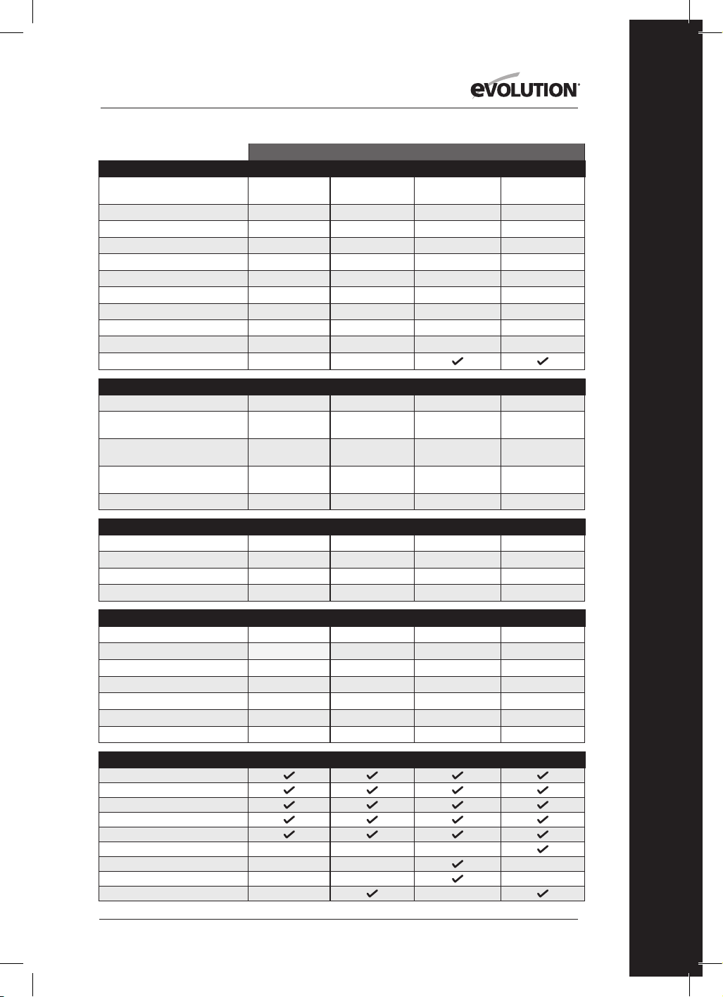
63
www.evolutionpowertools.com
FR
ÉTATS-UNIS
SPÉCIFICATIONS DE LA MACHINE R165CCSL
R185CCS R185CCSX R185CCSX+
N° du modèle: 026-0004
027-0004 027-0004C 027-0004A
Moteur UE (220-240V ~ 50Hz)
Moteur RU (110V ~ 50Hz)
Moteur USA (120V ~ 60 Hz) 10A
15A 15A 15A
Vitesse à vide (220-240V)
Vitesse à vide (110V et 120 V) 3900 min
-1
/ rpm
3700 min
-1
/ tpm 3700 min
-1
/ tpm 3700 min
-1
/ tpm
Poids 9,5 lb
10,8 lb 11,2 lb 11,2 lb
Angle du biseau de la lame max. 45˚
60° 45˚ 45°
Longueur du cordon d’alimentation 10 ft
13ft 13 ft 13ft
Type de base de la scie circulaire
Acier pressé
Aluminium coulé Aluminium coulé Aluminium coulé
Compatible avec les guides de découpe
CAPACITÉS DE COUPE R165CCSL
R185CCS R185CCSX R185CCSX+
Plaque en acier doux (épaisseur max.) 1/8"
1/4” 1/4” 1/4”
Structure carrée en acier doux
(épaisseur max. du mur)
1/8”
1/4” 1/4” 1/4”
Épaisseur de coupe max. (0°) 2-3/32"
2-1/2"
2-1/2”
(2-5/16” avec guide)
2-1/2”
(2-5/16” avec guide)
Épaisseur de coupe max. (45°) 1-11/32"
1-9/16"
1-13/16”
(1-5/8” avec guide)
1-13/16”
(1-5/8” avec guide)
Épaisseur de coupe max. (60°)
1”
CARACTÉRISTIQUES DE LA LAME R165CCSL
R185CCS R185CCSX R185CCSX+
Diamètre de la lame Ø 6-1/2"
Ø 7-1/4” Ø 7-1/4” Ø 7-1/4”
Nombre de dents 14
20 16 20
Diamètre d'alésage 25/32"
25/32” 25/32” 25/32”
Trait de coupe 1.7mm
1,7mm 1.7mm 1,7mm
NIVEAUX SONORES ET VIBRATOIRES R165CCSL
R185CCS R185CCSX R185CCSX+
Niveau de pression acoustique L
pa
92,4dB(A) K:3dB(A)
97,3dB(A) K=3 dB(A) 97,3dB(A) K=3 dB(A) 97,3dB(A) K=3 dB(A)
Niveau d’intensité acoustique L
wa
103,4dB(A) K:3dB(A)
105,3dB(A) K=3 dB(A) 105,3dB(A) K=3 dB(A) 105,3dB(A) K=3 dB(A)
Vibration - poignée principale (sciage du bois)
a
h,w
= 2,747m/s
2
a
h,w
= 3,347m/s
2
a
h,w
= 3,347m/s
2
a
h,w
= 3,347m/s
2
Vibration - poignée auxiliaire (sciage du bois)
a
h,w
= 2,619m/s
2
a
h,w
= 3,119m/s
2
a
h,w
= 3,119m/s
2
a
h,w
= 3,119m/s
2
Vibration - poignée principale (sciage du métal)
a
h,M
= 2,302m/s
2
a
h,M
= 3,572m/s
2
a
h,M
= 3,572m/s
2
a
h,M
= 3,572m/s
2
Vibration - poignée auxiliaire (sciage du métal)
a
h,M
= 2,239m/s
2
a
h,M
= 3,241m/s
2
a
h,M
= 3,241m/s
2
a
h,M
= 3,241m/s
2
Uncertainty K
1,5m/s
2
1,5m/s
2
1,5m/s
2
1,5m/s
2
ARTICLES FOURNIS R165CCSL
R185CCS R185CCSX R185CCSX+
Lame TCT multi-matériaux
Clé hexagonale (changement de lame)
Guide parallèle
Adaptateur du port à poussières
Raccord du tuyau à poussières
Boîte de transport
Guide de coupe (340mm x3)
Barre et vis du raccord (x4)
Voyant LED
PARTICULARITÉS

64
www.evolutionpowertools.com
RU / UE / AUS
R165CCSL R185CCS R185CCSX R185CCSX+
026-0001 /
026-0002 / 026-0003
027-0001C /
027-0002C / 027-0003C
027-0001 /
027-0002 / 027-0003
027-0001A /
027-0002A / 027-0003A
1200W 1600W 1600W 1600W
1200 W 1600W 1600W 1600W
3700 min
-1
/ tpm 3900 min
-1
/ tpm 3900 min
-1
/ tpm 3900 min
-1
/ tpm
3700 min
-1
/ tpm 3700 min
-1
/ tpm 3700 min
-1
/ tpm 3700 min
-1
/ tpm
4,3 kg 4,9 kg 5,1 kg 5,1 kg
45° 60° 45° 45°
3m 3m 3m 4m
Acier pressé Aluminium coulé Aluminium coulé Aluminium coulé
R165CCSL R185CCS R185CCSX R185CCSX+
3mm 6mm 3mm 6mm
3mm 6mm 3mm 6mm
53mm 64mm
64mm
(59mm avec guide)
64mm
(59mm avec guide)
34mm 40mm
47mm
(42mm avec guide)
47mm
(42mm avec guide)
24mm
R165CCSL R185CCS R185CCSX R185CCSX+
Ø 165mm Ø 185mm Ø 185mm Ø 185mm
14 20 16 20
20mm 20mm 20mm 20mm
1,7mm 1,7mm 1,7mm 1,7mm
R165CCSL R185CCS R185CCSX R185CCSX+
92,4dB(A) K:3dB(A) 97,3dB(A) K=3 dB(A) 97,3dB(A) K=3 dB(A) 97,3dB(A) K=3 dB(A)
103,4dB(A) K:3dB(A) 105,3dB(A) K=3 dB(A) 105,3dB(A) K=3 dB(A) 105,3dB(A) K=3 dB(A)
a
h,w
= 2,747m/s
2
a
h,w
= 3,347m/s
2
a
h,w
= 3,347m/s
2
a
h,w
= 3,347m/s
2
a
h,w
= 2,619m/s
2
a
h,w
= 3,119m/s
2
a
h,w
= 3,119m/s
2
a
h,w
= 3,119m/s
2
a
h,M
= 2,302m/s
2
a
h,M
= 3,572m/s
2
a
h,M
= 3,572m/s
2
a
h,M
= 3,572m/s
2
a
h,M
= 2,239m/s
2
a
h,M
= 3,241m/s
2
a
h,M
= 3,241m/s
2
a
h,M
= 3,241m/s
2
1,5m/s
2
1,5m/s
2
1,5m/s
2
1,5m/s
2
R165CCSL R185CCS R185CCSX R185CCSX+

65
www.evolutionpowertools.com
FR
VIBRATION
(1.5) Remarque: La mesure des vibrations a
été effectuée dans des conditions standard
conformément à : EN 62841-1: 2015,
EN 62841-2-5: 2014
Avertissement : Portez des protections
auditives!
La valeur de vibrations totale déclarée a été
mesurée conformément à une méthode d’essai
standard et peut être utilisée pour comparer un
outil avec un autre.
La valeur totale des vibrations déclarée peut
également être utilisée lors d'une évaluation
préliminaire d'exposition.
(1.6) AVERTISSEMENT: Lors de l’utilisation de
cette machine, l’opérateur peut être exposé à de
hauts niveaux de vibrations transmises à sa main
et à son bras.
Il se peut que l’opérateur développe le syndrome
de Raynaud. Ce syndrome peut diminuer
la sensibilité de la main à la température et
provoquer un engourdissement général.
Les personnes utilisant cette machine de
manière régulière ou prolongée doivent
surveiller attentivement l’état de leurs mains
et de leurs doigts. Si l'un des symptômes
devient apparent, consultez immédiatement un
médecin.
La mesure et l'évaluation de l’exposition de l’être
humain aux vibrations transmises par les
mains en milieu professionnel sont précisées
dans les normes suivantes :
EN 62841-1 et EN 62841-2-5
• Plusieurs facteurs peuvent influencer le
niveau de vibration effectif lors de l’utilisation,
comme l'état et l'orientation des surfaces
de travail et le type et l’état de la machine
utilisée. Avant chaque utilisation, vous devez
évaluer de tels facteurs et si possible, adopter
des pratiques professionnelles appropriées.
La gestion de ces facteurs peut aider à réduire
les effets des vibrations :
Manipulation
• Manipulez la machine avec soin
en lui laissant faire le travail.
• Évitez les efforts physiques excessifs sur
toutes les commandes de la machine.
• Prenez en considération votre sécurité et
votre stabilité ainsi que l'orientation de la
machine durant son utilisation.
Surface de travail
• Prenez en compte la matière de la surface de
travail, son état, sa densité, sa résistance,
sa rigidité et son orientation.
AVERTISSEMENT : L'émission de vibrations
durant l'utilisation effective de l'outil électrique
peut différer de la valeur totale déclarée en
fonction de la manière dont l'outil est utilisé.
Il est nécessaire d’identifier les mesures de
sécurité à adopter et de protéger l’opérateur
en fonction d’une estimation de l’exposition
dans les conditions effectives d’utilisation (en
tenant compte de toutes les étapes du cycle
d’opération, par exemple lorsque l’outil est mis à
l’arrêt, lorsqu’il tourne au ralenti,
en plus du déclenchement).
(1.7 ) ÉTIQUETTES ET SYMBOLES
AVERTISSEMENT : N’utilisez pas cette
machine si les étiquettes d’avertissement
et/ou d’instructions sont manquantes ou
endommagées. Contactez Evolution
Power Tools pour le remplacement des
étiquettes.
Remarque: Tous les symboles suivants ou
certains d'entre eux peuvent apparaître dans le
manuel ou sur le produit.
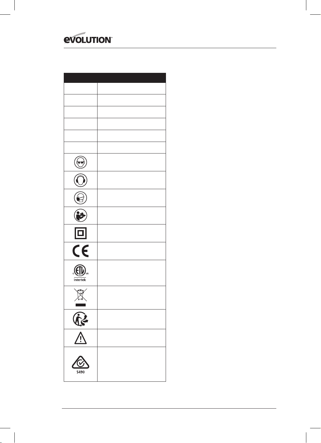
66
www.evolutionpowertools.com
(1.8)
Symbole Description
V
Volts
A
Ampères
Hz
Hertz
Min
-1
/ TPM
Vitesse
~
Courant alternatif
n
o
Vitesse à vide
Portez des lunettes de sécurité
Portez des protections auditives
Portez des protections contre la
poussière
Lire les instructions
Double isolation
Certification CE
Certification ETL
Déchets d'équipements
électriques
et électroniques
Triman - Collecte et recyclage
des déchets
Avertissement
(RCM) Regulatory Compliance Mark
(marque de conformité légale)
pour les équipements électriques et
électroniques. Norme australienne/
néo-zélandaise
(1.9) USAGE PRÉVU
POUR CET OUTIL ÉLECTRIQUE
AVERTISSEMENT : Ce produit est une scie
circulaire à commande manuelle conçue
pour fonctionner avec des lames Evolution
spécifiques. Utilisez uniquement des accessoires
conçus pour l'utilisation avec cette machine et/
ou ceux spécifiquement recommandés
par Evolution Power Tools Ltd.
Lorsqu'elle est équipée d'une lame appropriée,
cette machine peut être utilisée pour découper :
de l’acier doux, de l’aluminium, du bois
Remarque: Couper de l’acier galvanisé peut
réduire la durée de vie de la lame.
(1.10) USAGES PROSCRITS
POUR CET OUTIL ÉLECTRIQUE
AVERTISSEMENT: Ce produit est une scie
circulaire à commande manuelle et doit être
utilisé uniquement en tant que tel. Il ne doit en
aucun cas être modifié ou utilisé pour alimenter
tout autre appareil ou entraîner tout accessoire
autre que ceux mentionnés dans le présent
manuel d'instructions.
(1.11) AVERTISSEMENT: Cette machine
n'est pas conçue pour être utilisée par des
personnes (y compris les enfants) dont les
capacités physiques, sensorielles ou mentales
sont réduites, ou dénuées d'expérience ou de
connaissances, sauf si elles ont pu bénéficier,
par l'intermédiaire d’une personne responsable
de leur sécurité et capable d'utiliser la machine
en sécurité, d’une surveillance ou d'instructions
préalables concernant l’utilisation de la machine.
Les enfants doivent être surveillés pour garantir
qu'ils n'aient pas accès à cette machine et qu'ils
ne soient pas autorisés à jouer avec.
(1.12) SÉCURITÉ ÉLECTRIQUE
Cette machine est équipée de la fiche moulée
et du câble électrique adéquats pour le marché
désigné. Si le cordon d’alimentation est
endommagé, il doit être remplacé par un cordon
spécifique disponible auprès du fabricant ou de
son agent de maintenance.

67
www.evolutionpowertools.com
FR
(1.13) UTILISATION EN EXTÉRIEUR
AVERTISSEMENT: Si vous utilisez cet outil
en extérieur, ne l’exposez pas à la pluie et ne
l’utilisez pas dans des lieux humides pour assurer
votre protection. Ne placez pas l’outil sur des
surfaces humides. Utilisez un établi sec et propre,
si possible. Pour une protection supplémentaire,
utilisez un dispositif de courant différentiel
résiduel (DCR) qui interrompra l'alimentation si le
courant de fuite vers la terre excède 30 mA pour
30 ms. Vérifiez toujours le bon fonctionnement
du dispositif différentiel résiduel (DCR) avant
d’utiliser la machine.
Si vous devez utiliser une rallonge, celle-ci doit
convenir à l’utilisation en extérieur et cette
mention doit figurer sur l’étiquette.
Les instructions du fabricant doivent être
respectées lors de l’utilisation d’une rallonge.
(2.1) CONSIGNES GÉNÉRALES DE
SÉCURITÉ
(Ces consignes générales de sécurité pour les
outils électriques sont telles que spécifiées dans
EN 62841-1: 2015
).
AVERTISSEMENT : Lisez tous les avertissements
de sécurité et les instructions. Le non-respect des
avertissements et des instructions peut causer
des électrocutions, des incendies et/ou des
blessures graves.
Conservez tous les avertissements de sécurité et
toutes les instructions pour future référence. Le
terme « outil électrique » dans les avertissements
fait référence aux outils électriques fonctionnant
sur secteur (avec fil) ou sur batterie (sans fil).
(2.2) 1) Avertissements généraux de sécurité
des outils électriques [sécurité de l’aire de
travail]
a) L’espace de travail doit être propre et
suffisamment éclairé.
Les espaces sombres et encombrés sont propices
aux accidents.
b) Ne mettez pas en marche votre outil
électrique dans un environnement explosif, ou
en présence de liquide inflammable, de gaz ou
de poussière. Les outils électriques produisent
des étincelles qui peuvent faire enflammer la
poussière ou les vapeurs.
c) Tenez les enfants et les autres personnes
présentes éloignés lorsque vous utilisez un
outil électrique. Les distractions peuvent causer
une perte de contrôle.
(2.3) 2) Avertissements généraux de sécurité
des outils électriques [sécurité électrique]
a) Les fiches des outils électriques doivent
correspondre à la prise secteur utilisée. Ne
modifiez jamais la fiche, de quelque façon
que ce soit. N’utilisez jamais d’adaptateurs
de fiche avec des outils reliés à la terre. Les
fiches et prises non modifiées réduisent le risque
d’électrocution.
b) Évitez tout contact du corps avec des
surfaces reliées à la terre, telles que tuyaux,
radiateurs, cuisinières et réfrigérateurs. Le
risque d’électrocution est accru si votre corps est
relié à la terre.
c) N’exposez pas les outils électriques ni à la
pluie ni à l’humidité. La pénétration d’eau dans
ces outils accroît le risque d’électrocution.
d) Ne maltraitez pas le cordon d’alimentation.
N’utilisez jamais le cordon d’alimentation
pour transporter l’outil et ne débranchez
jamais l’appareil en tirant sur le cordon.
Gardez le cordon à l’écart de la chaleur, de
l’huile, d'objets tranchants et des pièces
en mouvement. Un cordon endommagé ou
emmêlé accroît le risque de choc électrique.
e) Pour les travaux à l’extérieur, utilisez
un cordon spécialement conçu à cet effet.
L’utilisation d’un cordon conçu pour l’usage
extérieur réduit le risque d’électrocution.
f) Si le fonctionnement de l’outil électrique
dans des endroits humides est inévitable,
utilisez une prise protégée par un dispositif
de courant différentiel résiduel (DCR).
L’utilisation d’un dispositif différentiel résiduel
réduit le risque de choc électrique.
(2.4) 3) Avertissements généraux de sécurité
des outils électriques [sécurité personnelle].
a) Restez attentif, prêtez attention au travail
que vous êtes en train d’effectuer et faites
preuve de bon sens lors de l’utilisation de tout
outil électrique. N’utilisez pas d’outil électrique
en état de fatigue ou sous l’influence de l’alcool,
de drogues ou de médicaments. Un moment
d’inattention pendant l’utilisation d’un outil
électrique peut entraîner des blessures graves.

68
www.evolutionpowertools.com
b) Utilisez un équipement de protection
individuel. Portez toujours une protection
oculaire. Des équipements de protection tels
que les masques anti-poussière, les chaussures
de sécurité anti-dérapantes, les casques ou
les protections acoustiques utilisés dans les
conditions appropriées réduiront le risque
de blessures.
c) Prévenez les démarrages impromptus.
Assurez-vous que l’interrupteur est en position
d’arrêt avant de brancher l’outil à une prise
secteur et/ou un bloc-piles, de ramasser ou
de transporter l’outil. Le fait de porter un outil
électrique avec le doigt sur son interrupteur ou
de brancher un outil dont l’interrupteur est en
position de marche peut causer un accident.
d) Retirez les clés de réglage ou les clés à
écrous du boulon de lame avant de mettre
l’outil en marche. Un outil ou une clé laissé sur
une pièce rotative d’un outil électrique pourrait
causer de graves dommages corporels.
e) Ne travaillez pas hors de portée. Gardez un
bon appui et un bon équilibre à tout moment.
Ceci permettra de mieux contrôler l’outil en cas
de situation imprévue.
f) Portez une tenue appropriée. Ne portez ni
vêtements amples, ni bijoux. Gardez les cheveux,
les vêtements et les gants à l’écart des pièces en
mouvement. Les vêtements amples, les bijoux et
les cheveux longs peuvent se prendre dans les
pièces en mouvement.
g) Si les outils sont équipés de dispositifs
de dépoussiérage, assurez-vous qu’ils sont
connectés et correctement utilisés. L’usage de
ces dispositifs de collecte des poussières peut
réduire les dangers présentés par la poussière.
h)Ne soyez pas trop sûr de vous et n’ignorez
pas les précautions de sécurité d’un outil
à cause de la familiarité acquise avec son
utilisation fréquente. Toute action imprudente
risque d’entraîner de graves blessures en une
fraction de seconde.
(2.5) 4) Avertissements généraux de sécurité
des outils électriques [utilisation et entretien
des outils électriques].
a) Ne forcez pas sur l’outil électrique. Utilisez
l’outil approprié pour le travail. Un outil approprié
exécutera le travail mieux et de façon moins
dangereuse s’il est utilisé dans les limites prévues.
b) N’utilisez pas l’outil électrique si
l’interrupteur ne permet pas de le mettre en
marche ou de l’arrêter. Un outil électrique
qui ne peut pas être contrôlé par son
interrupteur est dangereux et doit être réparé.
c) Débranchez l’outil de sa source électrique
avant d’effectuer des réglages, de changer les
accessoires ou de ranger l’outil. Ces mesures
de sécurité préventives réduisent les risques de
démarrage accidentel de l’outil.
d) Lorsque vous avez fini de vous en servir,
rangez les outils électriques hors de portée
des enfants et empêchez les personnes qui
ne connaissent pas l’outil électrique ou les
présentes instructions de l’utiliser. Les outils
électriques sont dangereux lorsqu’ils sont utilisés
par des personnes non initiées.
e) Entretenez les outils électriques. Vérifiez
l'alignement ou l'attache des pièces mobiles,
la rupture des pièces mobiles et toute autre
condition susceptible de nuire au bon
fonctionnement de l'outil électrique. En cas de
dommages, faites réparer l’outil avant de l’utiliser
de nouveau. Beaucoup d’accidents sont causés
par des outils électriques mal entretenus.
f) Gardez les outils de coupe bien affûtés
et propres. Des outils de coupe correctement
entretenus et dont les tranchants sont bien
affûtés risquent moins de se bloquer et sont plus
faciles à contrôler.
g) Utilisez l’outil, les accessoires et les
embouts, etc., conformément à ces
instructions pour les applications pour
lesquelles ils sont conçus, en tenant compte
des conditions et du type de travail à
exécuter. L’usage d’un outil électrique à d’autres
fins que celles prévues peut entraîner des
situations dangereuses.
h)Faites en sorte que les poignées et les
surfaces de prises soient toujours sèches,
propres et dénuées d’huile ou de graisse. Des
poignées ou des surfaces de prises glissantes ne
permettent pas la manipulation et le contrôle
de l'outil en toute sécurité lors de situations
imprévues.
(2.6) 5) Avertissements généraux de sécurité
des outils électriques [réparation]
a) Les réparations doivent être confiées à un
technicien qualifié, utilisant exclusivement
des pièces identiques à celles d’origine. Ceci
assurera le maintien de la sécurité de l’appareil.

69
www.evolutionpowertools.com
FR
(2.7) CONSEILS DE SANTÉ
AVERTISSEMENT: Lors de l'utilisation de cette
machine, des particules de poussière peuvent
être engendrées. Dans certains cas, en fonction
des matériaux avec lesquels vous travaillez, cette
poussière peut se révéler particulièrement néfaste.
Si vous suspectez que la peinture à la surface du
matériau que vous souhaitez couper contient du
plomb, demandez les conseils d'un professionnel.
Les peintures au plomb doivent être retirées
uniquement par un professionnel. Vous ne devez
pas tenter de les retirer vous-même.
Une fois que la poussière s'est déposée sur les
surfaces, un contact entre la main et la bouche
peut donner lieu à l'ingestion de plomb.
L’exposition au plomb, même en faible quantité,
est susceptible de provoquer des lésions
irréversibles du cerveau ou du système nerveux.
Les jeunes enfants et les enfants à naître sont
particulièrement vulnérables.
Il est conseillé de considérer les risques associés
aux matériaux avec lesquels vous travaillez et de
réduire les risques d'exposition.
Certains matériaux pouvant engendrer des
poussières potentiellement dangereuses pour
votre santé, nous vous conseillons d'utiliser un
masque agréé avec des filtres interchangeables
lors de l'utilisation de cette machine.
Vous devriez toujours :
• Travailler dans un endroit bien aéré.
• Travaillez en portant un équipement de
protection agréé tel que des masques anti-
poussière spécialement conçus pour filtrer les
particules microscopiques.
(2.8) AVERTISSEMENT: lors de l’utilisation
de tout outil électrique, des corps étrangers
risquent d’être projetés vers vos yeux, risquant
de les endommager gravement. Avant de
commencer à utiliser un outil électrique, portez
toujours des lunettes de protection munies
d'écrans latéraux ou un masque facial intégral si
nécessaire.
CONSIGNES DE SÉCURITÉ POUR TOUTES LES
SCIES [Procédures de coupes]
a) DANGER : N'approchez pas vos mains de
la zone de coupe ou de la lame. Gardez votre
seconde main sur la poignée auxiliaire, ou sur
le boîtier moteur. Si vos deux mains tiennent la
scie, elles ne peuvent pas être coupées par la lame.
b) Ne placez pas vos mains sous la pièce
usinée. Le carter ne peut pas vous protéger de la
lame sous la pièce usinée.
c) Adaptez la profondeur de la coupe à
l'épaisseur de la pièce usinée. Les dents de la
lame ne doivent pas entièrement dépasser sous
la pièce usinée.
d) Ne tenez jamais la pièce à usiner dans vos
mains ou entre vos jambes pendant la coupe.
Sécurisez la pièce à usiner avec un support
stable. Il est important de soutenir la pièce
correctement pour réduire les risques d'accident
corporel, de grippage de la lame ou de perte de
contrôle.
e) Tenez l'appareil électrique par les surfaces
de prises isolées lorsqu'il est susceptible
d'entrer en contact avec des câbles cachés
ou son propre cordon d'alimentation.
Tout contact avec un câble «sous tension»
entraînerait une «mise sous tension» des parties
métalliques exposées de l’outil et l'électrocution
de l'opérateur.
f) Lors d'un sciage, utilisez toujours un guide
de refend ou longitudinal. Cela augmente la
précision de la coupe et réduit les risques de
grippage de la lame.
g) Utilisez toujours des lames aux bonnes
dimensions et de forme adaptée (en losange
contre circulaire) ou des alésages. Les lames
qui ne sont pas adaptées au système de
montage de la scie fonctionneront de manière
excentrée ce qui engendrera une perte de
contrôle.
h) N'utilisez jamais de rondelles de lame
ou de boulons de lame endommagés ou
inadaptés. Les boulons et rondelles de lame
ont été spécialement conçus pour votre scie
afin d'assurer des performances optimales et la
sécurité lors de son utilisation.
(3.2) [Causes des effets de recul et comment
les éviter]
L'effet de recul se traduit par une réaction
soudaine à un coincement, un blocage ou un
mauvais alignement de la lame qui soulève
la scie et libère la lame de la pièce à usiner en
direction de l'utilisateur ;
La lame peut se coincer ou se bloquer fermement
lorsque le trait de scie se resserre. Si cela se
produit, la lame cale et le moteur réagit en
repoussant rapidement l'appareil vers l'opérateur;

70
www.evolutionpowertools.com
Si la lame se tord ou dérive de l'alignement de la
coupe, les dents situées sur le tranchant arrière
de la lame peuvent s'enfoncer dans la surface
supérieure du bois, éjectant ainsi la lame du trait
de scie vers l'opérateur.
(3.3) L'effet de recul résulte d'une mauvaise
utilisation de la scie et/ou du non-respect des
procédures ou conditions d'utilisation et peut
être évité en prenant les précautions adéquates
indiquées ci-dessous.
a) Tenez fermement la scie avec vos deux
mains et positionnez vos bras de façon
à résister aux forces de l'effet de recul.
Placez-vous sur l'un des côtés de la lame, mais
pas dans son alignement. Même si l'effet de
recul peut entraîner l'éjection de la lame vers
l'arrière, il peut être contrôlé par l'utilisateur si les
précautions adéquates sont prises.
b) Si les lames se grippent ou si l'interruption
de la coupe est nécessaire, quelle qu'en soit
la raison, relâchez la gâchette et maintenez la
scie immobile dans le matériau jusqu'à l'arrêt
complet de la lame. Pour éviter tout effet de
recul, n'essayez jamais de retirer la scie de
la pièce, ni de la tirer en arrière lorsque les
lames sont encore en mouvement. Examinez
les lames et prenez les mesures correctives
nécessaires pour éviter tout grippage.
c) Lorsque vous redémarrez une scie dans une
pièce à usiner, placez la lame au centre du
trait de scie et vérifiez que les dents ne sont
pas engagées dans le matériau. Si la lame se
grippe, elle peut se soulever ou être envoyée en
arrière lors du redémarrage de la scie.
d) N'utilisez pas de lames émoussées ou
endommagées. Les lames mal affûtées ou
mal réglées créeront un trait de scie étroit qui
entraînera une friction excessive, un grippage de
la lame et un effet de recul.
e) Les leviers d'ajustement et de verrouillage
de biseau et la profondeur de la lame doivent
être serrés et sécurisés avant de procéder à
une coupe. Un changement de réglage de la
lame durant la coupe peut entraîner un grippage
et un effet de recul.
f) Les leviers d'ajustement et de verrouillage
de la profondeur de la lame et du biseau
doivent être serrés et sécurisés avant de
procéder à la coupe. Un changement de
réglage de la lame durant la coupe peut
entraîner le grippage et un effet de recul.
g) Redoublez de prudence lorsque vous
effectuez une «coupe en plongée» dans
des murs existants ou autres parties non
apparentes. La coupe d'objets due à une lame
en saillie peut provoquer un effet de recul.
FONCTIONNEMENT DU CARTER
INFÉRIEUR
a) Vérifiez que le carter inférieur se verrouille
correctement avant chaque utilisation. Ne
démarrez pas la scie si le carter inférieur
ne bouge pas librement et ne se ferme pas
instantanément. Ne maintenez et ne bloquez
jamais le carter inférieur en position ouverte.
En cas de chute accidentelle, le carter inférieur
peut se déformer. Relevez le carter inférieur avec
la poignée de rétractation, puis assurez-vous
qu'il bouge librement et qu'il ne touche pas la
lame ni aucune autre pièce, quels que soient
l'angle et la profondeur de coupe.
b) Vérifiez le bon fonctionnement du ressort
du carter inférieur. Si le carter et le ressort ne
fonctionnent pas correctement, ils doivent
être soumis à une opération d'entretien avant
toute utilisation. Des pièces endommagées,
des dépôts gommeux ou une accumulation de
débris peuvent ralentir le fonctionnement du
carter inférieur.
c) Ne rétractez manuellement le carter
inférieur que pour réaliser des «coupes
en plongée» et des «coupes composées».
Relevez le carter inférieur en rétractant
la poignée, puis relâchez-le dès que la
lame entre dans le matériau. Pour tous les
autres types de coupes, le carter inférieur doit
fonctionner automatiquement.
k) Vérifiez toujours que le carter inférieur
couvre la lame avant de poser la scie sur
un banc ou au sol. Une lame non protégée
et continuant de tourner peut entraîner le
basculement de la scie en arrière qui coupera
tout sur son passage. Tenez compte du temps
d'arrêt de la lame après le relâchement de la
gâchette.
CONSIGNES DE SÉCURITÉ
SUPPLÉMENTAIRES
POUR LES SCIES CIRCULAIRES
a) N'utilisez pas de lames en acier à coupe
rapide (HSS).
b) Contrôlez la machine et la lame
avant chaque utilisation. N'utilisez pas

71
www.evolutionpowertools.com
FR
de lames déformées, fendues, usées ou
endommagées de quelque façon que ce soit.
c) N'utilisez jamais la scie sans le système
de carter de protection d'origine. Ne
verrouillez pas le carter mobile en position
ouverte. Assurez-vous que le carter fonctionne
librement sans se bloquer.
d) N'utilisez que des lames correspondant aux
caractéristiques indiquées dans ce manuel.
Avant d'utiliser des accessoires, assurez-vous
toujours que le nombre maximal de tours par
minute autorisé d'un accessoire correspond à
celui de la machine.
e) N’utilisez aucune lame circulaire abrasive.
f) Utilisez uniquement des lames dont le
diamètre correspond
aux marquages.
(3.4) AVERTISSEMENT: S'il manque des pièces,
n'utilisez pas la machine jusqu'à ce que les pièces
manquantes soient remplacées. Le non-respect
de cette règle pourrait provoquer des blessures
graves.
(4.1) PRISE EN MAIN - DÉBALLAGE
Attention: Cet emballage contient des objets
tranchants. Faites attention lors du déballage.
Retirez la machine et les accessoires fournis
de l'emballage. Vérifiez soigneusement que la
machine est en bonne condition et que vous
disposez de tous les accessoires listés dans ce
manuel. Assurez-vous que tous les accessoires
sont complets.
S’il manque une ou plusieurs pièces, renvoyez la
machine et ses accessoires dans leur emballage
d’origine au revendeur.
Ne jetez pas l’emballage. Conservez-le en bon
état tout au long de la période de garantie. Jetez
l’emballage d’une manière responsable pour
l’environnement. Recyclez si possible.
Ne laissez pas les enfants jouer avec des
sacs plastiques vides, en raison du risque de
suffocation.
(4.3) MANUELS D’INSTRUCTIONS
EVOLUTION
Evolution Power Tools fournit un manuel
d’instructions avec chaque produit.
Chaque manuel spécifique est spécialement
conçu et rédigé pour fournir des informations
accessibles et utiles quant à l’utilisation en
toute sécurité du produit, son entretien et les
précautions à prendre. Le référencement des
informations présentes dans le manuel permet à
l’opérateur d’exploiter pleinement le potentiel de
la machine en toute sécurité.
La politique de développement continu des
produits d’Evolution peut impliquer que, très
occasionnellement, le contenu d'un manuel ne
reflète pas complètement les dernières mises
à jour ou améliorations ayant été appliquées
à un produit en particulier. Les mises à jour
ou améliorations des caractéristiques d'un
produit peuvent survenir à la suite d’avancées
technologiques ou de changements du cadre
législatif du pays de destination, etc.
Si vous n’êtes pas certains d'un quelconque
aspect de l’utilisation ou de l’entretien d'un
produit Evolution ou des précautions à prendre,
contactez l’assistance téléphonique Evolution
appropriée qui pourra vous fournir des
informations à jour et davantage de conseils.
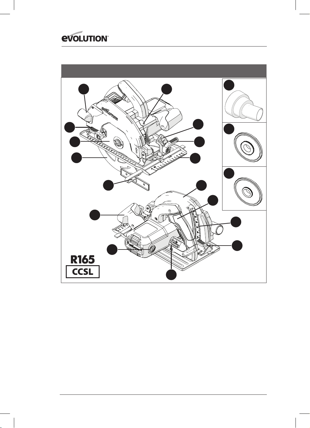
72
www.evolutionpowertools.com
1. PORT D'ÉJECTION DU MATÉRIAU DÉCOUPÉ
2. LEVIER ACTIONNÉ PAR LE POUCE
3. LAME TCT MULTI-MATÉRIAUX
4. CARTER DE LAME INFÉRIEUR
5. GUIDE PARALLÈLE
6. POIGNÉE ERGONOMIQUE AVANT
7. BROSSES EN CARBONE
8. CLÉ HEXAGONALE 8MM (CHANGEMENT DE LAME)
9. LEVIER DE BLOCAGE ET DE RÉGLAGE DE
PROFONDEUR
10. GRADUATION DE PROFONDEUR
11. POIGNÉE ARRIÈRE
12. CARTER DE LAME SUPÉRIEUR
13. PLAQUE EN ACIER DE PRÉCISION
14. LEVIER ACTIONNÉ PAR LE POUCE
15. RAPPORTEUR
16. BOUTON DE BLOCAGE DE L’ARBRE
17. RACCORD DU PORT À POUSSIÈRES
18. FLASQUE INTÉRIEURE DE LA LAME 25/32 POUCES
19. FLASQUE INTÉRIEURE DE LA LAME 5/8 POUCES
ÉTATS-UNIS
13
15
4
14
5
1
3
8
9
10
11
6
7
2
16
12
17
18
19
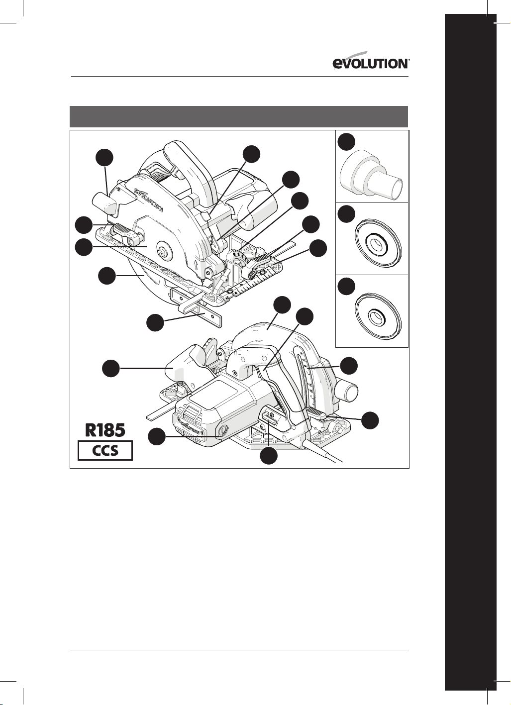
73
www.evolutionpowertools.com
FR
ÉTATS-UNIS
1. PORT D'ÉJECTION DU MATÉRIAU DÉCOUPÉ
2. LEVIER ACTIONNÉ PAR LE POUCE
3. LAME TCT MULTI-MATÉRIAUX
4. CARTER DE LAME INFÉRIEUR
5. GUIDE PARALLÈLE
6. POIGNÉE ERGONOMIQUE AVANT
7. BROSSES EN CARBONE
8. CLÉ HEXAGONALE 8MM (CHANGEMENT DE LAME)
9. LEVIER DE BLOCAGE ET DE RÉGLAGE DE
PROFONDEUR
10. GRADUATION DE PROFONDEUR
11. INTERRUPTEUR MARCHE/ARRÊT DE LA POIGNÉE
ARRIÈRE
12. CARTER DE LAME SUPÉRIEUR
13. PLAQUE EN ACIER DE PRÉCISION
14. LEVIER ACTIONNÉ PAR LE POUCE DE RÉGLAGE DU
BISEAU
15. RAPPORTEUR
16. BOUTON DE BLOCAGE DE L’ARBRE
17. VOYANT À LED
18. RACCORD DU PORT À POUSSIÈRES
19. FLASQUE INTÉRIEURE DE LA LAME 25/32 POUCES
20. FLASQUE INTÉRIEURE DE LA LAME 5/8 POUCES
13
15
17
18
19
20
4
14
5
1
3
8
9
10
11
6
7
2
16
12
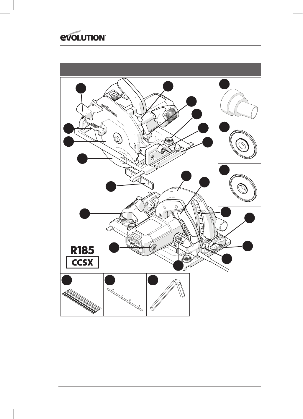
74
www.evolutionpowertools.com
ÉTATS-UNIS
1. PORT D'ÉJECTION DU MATÉRIAU
DÉCOUPÉ
2. LEVIER ACTIONNÉ PAR LE POUCE
3. LAME TCT MULTI-MATÉRIAUX
4. CARTER DE LAME INFÉRIEUR
5. GUIDE PARALLÈLE
6. POIGNÉE ERGONOMIQUE AVANT
7. BROSSES EN CARBONE
8. CLÉ HEXAGONALE 5/16”
(CHANGEMENT DE LAME)
9. LEVIER DE BLOCAGE ET DE
RÉGLAGE DE PROFONDEUR
10. GRADUATION DE PROFONDEUR
11. INTERRUPTEUR MARCHE/ARRÊT
DE LA POIGNÉE ARRIÈRE
12. CARTER DE LAME SUPÉRIEUR
13. PLAQUE EN ACIER DE PRÉCISION
COMPATIBLE AVEC LE GUIDE
14. LEVIER ACTIONNÉ PAR LE POUCE
15. RAPPORTEUR ARRIÈRE
16. BOUTON DE BLOCAGE DE L’ARBRE
17. VOYANT À LED
18. RACCORD DU PORT À POUSSIÈRES
19. FLASQUE INTÉRIEURE DE LA LAME
25/32 POUCES
20. FLASQUE INTÉRIEURE DE LA LAME
5/8 POUCES
21. BOUTONS PIVOTANTS DE
RÉGLAGE DU GUIDE
22. VIS PAPILLON DU BISEAU ARRIÈRE
23. 3x GUIDE 13-3/8”
24. 4x BARRES DU RACCORD DU GUIDE
25. CLÉ HEXAGONALE 1/8”
13
21
15
17
18
19
20
4
14
5
1
3
8
9
10
22
11
6
7
2
16
12
23 24 25

75
www.evolutionpowertools.com
FR
ÉTATS-UNIS
1. PORT D'ÉJECTION DU MATÉRIAU DÉCOUPÉ
2. LEVIER ACTIONNÉ PAR LE POUCE
3. LAME TCT MULTI-MATÉRIAUX
4. CARTER DE LAME INFÉRIEUR
5. GUIDE PARALLÈLE
6. POIGNÉE ERGONOMIQUE AVANT
7. BROSSES EN CARBONE
8. CLÉ HEXAGONALE 8MM (CHANGEMENT DE LAME)
9. LEVIER DE BLOCAGE ET DE RÉGLAGE DE
PROFONDEUR
10. GRADUATION DE PROFONDEUR
11. INTERRUPTEUR MARCHE/ARRÊT
DE LA POIGNÉE ARRIÈRE
12. CARTER DE LAME SUPÉRIEUR
13. PLAQUE EN ACIER DE PRÉCISION
COMPATIBLE AVEC LE GUIDE
14. LEVIER ACTIONNÉ PAR LE POUCE
15. RAPPORTEUR ARRIÈRE
16. BOUTON DE BLOCAGE DE L’ARBRE
17. VOYANT À LED
18. RACCORD DU PORT À POUSSIÈRES
19. FLASQUE INTÉRIEURE DE LA LAME 25/32 POUCES
20. FLASQUE INTÉRIEURE DE LA LAME 5/8 POUCES
21. BOUTONS PIVOTANTS DE RÉGLAGE DU GUIDE
22. VIS PAPILLON DU BISEAU ARRIÈRE
13
21
15
17
18
19
20
4
14
5
1
3
8
9
10
22
11
6
7
2
16
12

76
www.evolutionpowertools.com
13
15
4
14
5
1
3
8
9
10
11
6
7
2
16
12
1. PORT D'ÉJECTION DU MATÉRIAU DÉCOUPÉ
2. LEVIER ACTIONNÉ PAR LE POUCE
3. LAME TCT MULTI-MATÉRIAUX
4. CARTER DE LAME INFÉRIEUR
5. GUIDE PARALLÈLE
6. POIGNÉE ERGONOMIQUE AVANT
7. BROSSES EN CARBONE
8. CLÉ HEXAGONALE 8MM (CHANGEMENT DE LAME)
9. LEVIER DE BLOCAGE ET DE RÉGLAGE DE
PROFONDEUR
10. GRADUATION DE PROFONDEUR
11. POIGNÉE ARRIÈRE COMPRENANT L’INTERRUPTEUR
DE SÉCURITÉ MARCHE/ARRÊT
12. CARTER DE LAME SUPÉRIEUR
13. PLAQUE EN ACIER DE PRÉCISION
14. LEVIER ACTIONNÉ PAR LE POUCE
15. RAPPORTEUR
16. BOUTON DE BLOCAGE DE L’ARBRE
RU / UE / AUS

77
www.evolutionpowertools.com
FR
1. PORT D'ÉJECTION DU MATÉRIAU DÉCOUPÉ
2. LEVIER ACTIONNÉ PAR LE POUCE
3. LAME TCT MULTI-MATÉRIAUX
4. CARTER DE LAME INFÉRIEUR
5. GUIDE PARALLÈLE
6. POIGNÉE ERGONOMIQUE AVANT
7. BROSSES EN CARBONE
8. CLÉ HEXAGONALE 8MM (CHANGEMENT DE LAME)
9. LEVIER DE BLOCAGE ET DE RÉGLAGE DE
PROFONDEUR
10. GRADUATION DE PROFONDEUR
11. POIGNÉE ARRIÈRE COMPRENANT L’INTERRUPTEUR
DE SÉCURITÉ MARCHE/ARRÊT
12. CARTER DE LAME SUPÉRIEUR
13. PLAQUE EN ACIER DE PRÉCISION
14. LEVIER ACTIONNÉ PAR LE POUCE
15. RAPPORTEUR
16. BOUTON DE BLOCAGE DE L’ARBRE
17. RACCORD DU PORT À POUSSIÈRES
RU / UE
13
15
17
4
14
5
1
3
8
9
10
11
6
7
2
16
12

78
www.evolutionpowertools.com
13
18
15
17
20
21
22
4
14
5
1
3
8
9
10
19
11
6
7
2
16
12
1. PORT D'ÉJECTION DU MATÉRIAU DÉCOUPÉ
2. LEVIER ACTIONNÉ PAR LE POUCE
3. LAME TCT MULTI-MATÉRIAUX
4. CARTER DE LAME INFÉRIEUR
5. GUIDE PARALLÈLE
6. POIGNÉE ERGONOMIQUE AVANT
7. BROSSES EN CARBONE
8. CLÉ HEXAGONALE 8MM (CHANGEMENT DE LAME)
9. LEVIER DE BLOCAGE ET DE RÉGLAGE DE
PROFONDEUR
10. GRADUATION DE PROFONDEUR
11. POIGNÉE ARRIÈRE COMPRENANT L’INTERRUPTEUR
DE SÉCURITÉ MARCHE/ARRÊT
12. CARTER DE LAME SUPÉRIEUR
13. PLAQUE EN ACIER DE PRÉCISION COMPATIBLE AVEC
LE GUIDE
14. LEVIER ACTIONNÉ PAR LE POUCE
15. RAPPORTEUR ARRIÈRE
16. BOUTON DE BLOCAGE DE L’ARBRE
17. RACCORD DU PORT À POUSSIÈRES
18. BOUTONS PIVOTANTS DE RÉGLAGE DU GUIDE
19. VIS PAPILLON DU BISEAU ARRIÈRE
20. 3x GUIDE 340 mm
21. 4x BARRES DU RACCORD DU GUIDE
22. CLÉ HEXAGONALE 3 mm
RU / UE
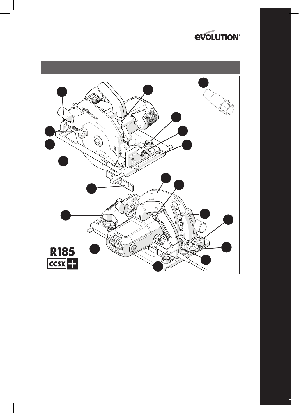
79
www.evolutionpowertools.com
FR
RU / UE
1. PORT D'ÉJECTION DU MATÉRIAU DÉCOUPÉ
2. LEVIER ACTIONNÉ PAR LE POUCE
3. LAME TCT MULTI-MATÉRIAUX
4. CARTER DE LAME INFÉRIEUR
5. GUIDE PARALLÈLE
6. POIGNÉE ERGONOMIQUE AVANT
7. BROSSES EN CARBONE
8. CLÉ HEXAGONALE 8MM (CHANGEMENT DE LAME)
9. LEVIER DE BLOCAGE ET DE RÉGLAGE DE
PROFONDEUR
10. GRADUATION DE PROFONDEUR
11. POIGNÉE ARRIÈRE COMPRENANT L’INTERRUPTEUR
DE SÉCURITÉ MARCHE/ARRÊT
12. CARTER DE LAME SUPÉRIEUR
13. PLAQUE EN ACIER DE PRÉCISION COMPATIBLE AVEC
LE GUIDE
14. LEVIER ACTIONNÉ PAR LE POUCE
15. RAPPORTEUR ARRIÈRE
16. BOUTON DE BLOCAGE DE L’ARBRE
17. RACCORD DU PORT À POUSSIÈRES
18. BOUTONS PIVOTANTS DE RÉGLAGE DU GUIDE
19. VIS PAPILLON DU BISEAU ARRIÈRE
13
18
15
17
4
14
5
1
3
8
9
10
19
11
6
7
2
16
12
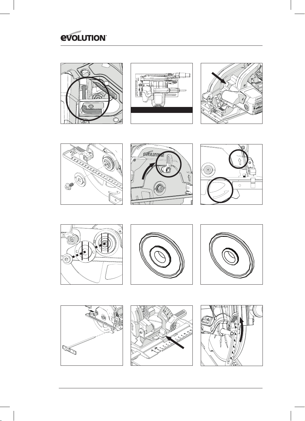
80
www.evolutionpowertools.com
Fig. 3Fig. 2
Fig. 4
Fig. 1
Fig. 8
Fig. 6Fig. 5
Fig. 9
Fig. 10
Fig. 7a Fig. 7b Fig. 7c

81
www.evolutionpowertools.com
FR
Fig. 11
Fig. 12
Fig. 13
Fig. 14
Fig. 15
Fig. 16
Fig. 17 Fig. 18
Fig. 21Fig. 20
Fig. 19
Fig. 22
1-2mm

82
www.evolutionpowertools.com
Fig. 27Fig. 26
Fig. 25
Fig. 30 Fig. 31
Fig. 34
Fig. 24Fig. 23
Raccord du port à
poussières US
Raccord du port à
poussières UE
Fig. 28
Fig. 29
Fig. 32 Fig. 33

83
www.evolutionpowertools.com
FR
(10) PRÉPARATION
AVERTISSEMENT : Débranchez toujours la
scie de l’alimentation électrique avant de faire des
réglages.
Remarque: Ces machines sont équipées d'un
cordon et d'une fiche dont l’utilisation est
approuvée dans le pays pour lequel ils sont prévus.
N’altérez pas le cordon d'alimentation et ne le
modifiez pas.
(10.1) INSTALLATION/RETRAIT
D’UNE LAME
AVERTISSEMENT: N'utilisez que des lames
Evolution (ou des lames approuvées par Evolution
Power Tools) conçues pour être utilisées avec ces
machines. Assurez-vous que la vitesse maximale
de la lame est compatible avec la machine.
Cette opération doit être réalisée uniquement
quand la machine est débranchée de sa source
d'alimentation.
Remarque : Nous recommandons à l'opérateur de
porter des gants de protection lors de l'installation
ou du changement de la lame.
• Repérez la clé hexagonale de changement de
lame fournie qui se trouve dans le dispositif de
rangement embarqué (au même endroit sur
toutes les machines). (Fig. 1)
• Placez la scie sur une surface plane et sûre.
Remarque: En prenant les précautions
nécessaires, toutes les machines peuvent être
posées en équilibre sur l'extrémité plate du
carter moteur (Fig. 2) afin de pouvoir accéder
facilement à la lame et aux fixations de la lame.
• Repérez le bouton de blocage de l’arbre de
la machine (au même endroit sur toutes les
machines). Verrouillez l’arbre de la machine en
appuyant sur le bouton de blocage de l’arbre.
(Fig. 3).
Remarque: Le blocage de l’arbre sera facilité
par le pivotement de la lame à la main tout en
appuyant doucement sur le bouton de blocage
de l’arbre.
• À l’aide de la clé hexagonale, desserrez et
retirez la vis à tête creuse de l’arbre, les fixations
associées et la flasque d’entrainement extérieure
de la lame. (Fig. 4)
Remarque: La vis à tête creuse de l’arbre est
pourvue d’un filetage standard. Faites tourner la
vis dans le sens des aiguilles d'une montre pour la
serrer. Faites tourner la vis dans le sens inverse des
aiguilles d'une montre pour la desserrer.
• Rangez la flasque extérieure de la lame et les
fixations associées dans un lieu sûr.
• Faites pivoter le carter de lame inférieur dans le
carter de lame supérieur grâce au levier manuel
à actionner avec le pouce. (Fig. 5)
• Retirez soigneusement la lame (s’il y en a une)
de la machine.
• Nettoyez méticuleusement les flasques
d’entrainement extérieures et intérieures de
la lame.
Remarque: Vous pouvez laisser la flasque
intérieure de la lame en place si vous le souhaitez,
mais vous devez la contrôler et la nettoyer
soigneusement. Si vous décidez de la retirer de la
machine, remettez-la dans la même position en
suivant la même orientation qu’avant son retrait.
• Nettoyez méticuleusement la zone de l’alésage
de la lame (des deux côtés), à l’endroit où les
flasques de la lame se touchent et bloquent
la lame.
• Installez la (nouvelle) lame.
• Assurez-vous que la direction des flèches de
rotation imprimées sur la lame correspond au
sens de rotation des flèches qui se trouvent
sur les carters inférieurs et supérieurs de la
machine. (Fig. 6)
• Réinstallez la bride d’entrainement extérieure,
la vis à tête creuse de l’arbre et les fixations
associées.
Remarque: La flasque d’entrainement extérieure
est pourvue d'un alésage spécialement usiné
comportant deux «pièces plates» opposées. (Fig.
7a) Ces «pièces plates» s’enclenchent avec deux
«pièces plates» complémentaires présentes sur
l’arbre de la machine.
• Réenclenchez le verrouillage de l’arbre et serrez
la vis à tête creuse de l’arbre à l’aide de la clé
hexagonale.
• Relâchez le bouton de blocage de l’arbre

84
www.evolutionpowertools.com
• Rangez la clé hexagonale dans l’emplacement
qui lui est dédié.
• Vérifiez que le verrou de l'arbre a été
complètement desserré en faisant tourner
manuellement la lame.
• Vérifiez le bon fonctionnement du carter de
lame inférieur.
Remarque : Pour le marché nord-américain
uniquement, une flasque d’arbre bilatérale
est incluse pour l’utilisation de lames
pourvues d’un alésage de 1 pouce (Fig.7b) et
de lames pourvues d’un alésage de 5/8 pouce
(Fig.7c).
(11) GUIDE PARALLÈLE
Un guide parallèle (Fig. 8) pouvant se révéler
particulièrement utile lors d’une découpe
longitudinale est fourni avec toutes les machines
CCS. Le guide peut être monté à l’avant de la
plaque en acier. Insérez le bras du guide dans
la fente rectangulaire située de chaque côté (à
l’avant) de la plaque en acier embouti et faites-le
glisser sous la vis de blocage et de réglage située
au centre. (Fig. 9)
Remarque: Le guide parallèle peut être monté de
chaque côté de la plaque en acier.
AVERTISSEMENT : Montez et réglez le guide
uniquement quand la machine est débranchée de
sa source d'alimentation.
Remarque : Le bras du guide parallèle doit passer
à travers toutes les fentes rectangulaires de la
plaque en acier.
AVERTISSEMENT : Il peut s’avérer dangereux
d'installer le guide parallèle et de tenter de l’utiliser
si le bras ne passe qu’à travers une (1) des fentes
rectangulaires usinées sur la plaque en acier.
Réglez le guide parallèle de sorte qu'il se trouve
à la distance requise de la lame et serrez la vis de
réglage. Vérifiez que le guide parallèle est parallèle
à la lame de la scie.
(12) RÉGLAGE DE LA PROFONDEUR DE
COUPE
Remarque: Toutes les machines CCS partagent
les mêmes équipements de réglage de la
profondeur et utilisent la même technique de base
pour régler la profondeur de la lame.
• Desserrez le mécanisme de blocage et de
réglage de la profondeur en levant le levier de
fonctionnement. (Fig. 10)
• Réglez/repositionnez la plaque en acier pour
sélectionner la profondeur de coupe souhaitée
(la distance à laquelle la lame avance dans la
plaque en acier).
Remarque: Vous trouverez une graduation
de profondeur sur le cadran de réglage de
la profondeur comportant un trait de repère
correspondant sur la zone adjacente du carter
de lame supérieur de la machine. (Fig. 11)
L’utilisation de ces fonctionnalités permet un
réglage plus rapide.
Remarque : Si la graduation de profondeur et
le trait de repère sont extrêmement utiles car ils
permettent de régler rapidement la profondeur de
coupe, vous devez toujours les utiliser en tant que
guide pour le réglage souhaité.
Si vous avez besoin d'une profondeur de coupe
très précise, le réglage de la lame doit être effectué
et vérifié à l’aide d'une règle d’ingénieur de
précision (non fournie) ou d'un outil similaire et la
lame ajustée en conséquence.
• Dans la plupart des cas, la profondeur de coupe
doit être réglée sur la valeur correspondant
à l’épaisseur du matériau à découper, plus
l'épaisseur de la moitié d'une dent de scie (du
bout de la dent jusqu’à sa racine). (Fig.12)
• Serrez le mécanisme de blocage et de réglage
de la profondeur en abaissant le levier de
fonctionnement pour bien verrouiller la
machine dans la position souhaitée.
(13) RÉGLAGE DE L’ANGLE
DE COUPE (BISEAU)
Toutes les machines CCSL et CCSX ont la capacité
d'incliner la lame jusqu’à 45° et toutes les
machines CCS ont la capacité d'incliner la lame
jusqu’à 60° à gauche. Il est donc possible de
réaliser des coupes en biseau.
Remarque : La lame est en position verticale
lorsque le rapporteur indique 0°.

85
www.evolutionpowertools.com
FR
Remarque: Un rapporteur (0°- 45° ou 0°- 60°)
est inclus sur le cadran de blocage du biseau
situé à l’avant de la plaque en acier. Cet outil sert
à régler rapidement l’angle du biseau mais doit
uniquement servir de guide.
Si vous avez besoin d'un angle de biseau très
précis, le réglage de la lame doit être effectué et
vérifié à l’aide d'un calibre d’angle Vernier (non
fourni) et la lame ajustée en conséquence.
• Desserrez le mécanisme de blocage du biseau
situé à l’avant de la machine en soulevant le
levier. (Fig. 13)
• Inclinez la lame selon l’angle souhaité, comme
indiqué sur le rapporteur du cadran. (Fig. 14)
• Serrez bien le mécanisme de blocage du biseau
après avoir atteint l’angle du biseau souhaité en
abaissant le levier.
(14) CONSEILS D’UTILISATION
(VÉRIFICATIONS AVANT UTILISATION)
Remarque : Comme tous les cadres d'utilisation
sont uniques et divers, Evolution Power Tools
propose les conseils généraux suivants concernant
les procédures et pratiques d'utilisation en toute
sécurité à l’attention de l’utilisateur.
Ces conseils ne peuvent se révéler exhaustifs
car Evolution ne peut contrôler le type d’atelier
ou d’environnement de travail dans lequel ces
machines peuvent être utilisées.
Nous incitons l’utilisateur à demander conseil
à une autorité compétente ou au superviseur
d’atelier s'il n’est pas sûr d’un quelconque aspect
lié à l’utilisation de ces machines.
Il est important de réaliser des vérifications de
sécurité de routine (à chaque utilisation) avant que
l’utilisateur n’utilise la machine.
AVERTISSEMENT : Ces vérifications de sécurité
avant utilisation doivent être effectuées lorsque la
machine est débranchée de la prise électrique.
• Vérifiez que tous les carters de sécurité
fonctionnent correctement et que toutes les
poignées/vis de réglage sont bien serrées.
• Vérifiez que la lame est bien fixée et
correctement installée. Assurez-vous également
d’avoir choisi une lame de scie adaptée au
matériau à découper.
• Vérifiez l’état du cordon d’alimentation.
• Si possible, fixez la pièce à usiner à l’aide d'une
pince sur une structure de soutien rigide comme
un établi, des tréteaux ou une surface similaire.
• L'opérateur doit toujours être conscient de
la position et de l'acheminement du câble
d’alimentation.
(15) EPI
• L’opérateur doit porter tous les EPI
(équipements de protection individuels)
adéquats et nécessaires à la réalisation de la
tâche prévue.
Cela peut comprendre des lunettes de sécurité,
un masque facial intégral, un masque à
poussière, des chaussures de sécurité, etc.
Remarque : Toutes les machines de série CCS sont
équipées d’un projecteur de débris sur la ligne
de coupe. Ce dispositif dirige l’air d’un ventilateur
alimenté par le moteur en direction de la zone
située à l’avant de la lame pour que la ligne de
coupe soit relativement dénuée de débris. Cet
équipement permet à l’opérateur de mieux voir et
suivre la progression de la lame de la scie le long de la
découpe et aux lignes de marquage de rester visibles.
AVERTISSEMENT : Toute poussière générée
présente un risque potentiel pour la santé.
Certains matériaux peuvent se révéler
particulièrement dangereux et l’opérateur doit
toujours porter un masque anti-poussière adapté
au matériau usiné. Recherchez l’avis et l’aide d'un
professionnel si l’opérateur doute de la toxicité
potentielle du matériau à découper.
AVERTISSEMENT : N’utilisez jamais ces machines
pour découper de l’amiante ou tout matériau
contenant de l’amiante ou suspecté d’en contenir.
Consultez et informez les autorités compétentes
et demandez davantage de conseils si vous
suspectez une contamination à l’amiante.
(16) INTERRUPTEURÀ GÂCHETTE
MARCHE/ARRÊT
Remarque : Toutes les machines destinées aux
marchés européens et australiens sont équipées
d’un interrupteur à gâchette de «démarrage
de sécurité» afin de renforcer la sécurité de

86
www.evolutionpowertools.com
l’opérateur. (Fig.15)
Pour démarrer le moteur :
• Avec votre pouce, appuyez sur le bouton
de verrouillage de sécurité situé à côté de la
poignée.
• Relâchez l'interrupteur à gâchette.
Pour arrêter le moteur:
• Relâchez l'interrupteur à gâchette.
AVERTISSEMENT : Ne démarrez jamais le moteur
si la lame de la scie est en contact direct avec
n’importe quelle surface de la pièce à usiner.
Remarque: Les machines destinées au marché
nord-américain sont équipées d’un interrupteur
à gâchette MARCHE/ARRÊT qui ne comprend
pas d’interrupteur à gâchette de «démarrage de
sécurité».
AVERTISSEMENT : Si la scie est en marche (le voyant
LED en position «ON»), évitez de démarrer le
moteur accidentellement en la soulevant d’un
établi ou d’une surface similaire. Le fait de relâcher
accidentellement l’interrupteur à gâchette
MARCHE/ARRÊT (situé dans la poignée principale)
en soulevant la machine en veille démarrera le
moteur.
GUIDES DE DÉCOUPE
Les machines Evolution de la gamme CCSX
(consultez la page des caractéristiques pour
les modèles concernés) ont été conçues et
équipées de manière à être compatibles avec
les guides de découpe.
Remarque: Toute scie circulaire pouvant être
utilisée avec un guide de découpe disposera d’un
profilé le long de la surface inférieure de la plaque
en acier (Fig. 16)
Les machines Evolution équipées d'un tel profilé
peuvent être fixées et utilisées avec la plupart des
guides de découpe actuellement disponibles.
Remarque: Consultez la documentation fournie
avec le guide par son fabricant. La documentation
fournie décrira normalement les instructions de
montage du guide ainsi que les informations
concernant les bonnes pratiques de travail
devant être respectées lors de l’utilisation d’un tel
équipement.
Il est possible d'utiliser des guides de découpe
lorsque:
• L’utilisation d'une scie circulaire ou à tronçonner
risque de poser des problèmes de santé et
de sécurité ou d’autres problèmes pratiques
dans l’environnement de travail. Par exemple,
lors d'un travail sur un site de construction
nécessitant un contrôle extrêmement
rapproché et précis, (travail sur un toit ou une
plateforme d’échafaudage, etc.), l’utilisation
d’un guide de découpe peut élargir les
possibilités d’opération de l’utilisateur de
manière sûre.
• Il est nécessaire de réaliser des découpes
précises en long ou en large sur de grandes
pièces à usiner. Par exemple sur des cadres,
portes, grandes planches ou panneaux muraux,
etc., un guide de découpe peut potentiellement
éliminer la nécessité d’utiliser une scie circulaire
«à main levée».
Remarque: Les machines Evolution compatibles
avec les guides de découpe sont équipées de deux
(2) cames qui passent dans le profilé de la plaque
en acier (une à chaque extrémité).
Les «boutons pivotants» (Fig. 17) permettent à
l’utilisateur de faire pivoter ces cames.
Le réglage de ces cames réduira légèrement la
largeur effective du profilé de la plaque en acier.
Cette opération peut se révéler nécessaire pour
s’adapter à aux infimes variations de la largeur du
rail pouvant survenir lors de l’extrusion du guide.
Les largeurs des rails des guides produits par
différents fabricants peuvent également varier
légèrement.
Remarque: L’utilisateur doit régler ces cames de
sorte que, lorsque la machine est correctement
placée sur un guide, elle puisse facilement et
doucement être déplacée vers l’avant ou vers
l’arrière sans aucun mouvement latéral (jeu)
détectable.

87
www.evolutionpowertools.com
FR
GUIDES DE DÉCOUPE EVOLUTION
Certaines machines Evolution (selon le modèle et
le marché de destination) sont fournies avec un
guide de découpe.
Remarque: Les clients peuvent acheter les
guides de découpe Evolution en option à l’achat.
Contactez votre fournisseur ou Evolution Power
Tools pour en savoir plus.
LE GUIDE
Le système de guide Evolution est composé de
deux (2) ou trois (3) sections en alliage extrudé de
précision.
(Fig. 18) Ces sections doivent être assemblées à
l’aide des barres d'assemblage fournies. (Fig. 19)
Assemblage des sections (Fig. 19):
• Faites glisser les barres dans les fentes en «T»
situées sur la surface inférieure des extrusions.
• Vérifiez que les barres sont insérées à la même
longueur (environ) dans chacune des sections
à assembler.
• Serrez les vis à tête creuse pour fixer les sections
les unes aux autres.
Remarque: Il est important de laisser un petit
espace de1 à 2mm entre les sections assemblées.
Grâce à cela, lorsqu'une scie circulaire est placée
et utilisée avec un guide de découpe transversale
Evolution, elle glissera facilement tout le long du
guide.
INTÉGRATION DE LA SCIE SUR LE
GUIDE
Remarque: Les consignes suivantes s’appliquent
aux scies circulaires et au guide de découpe
Evolution. Consultez les informations fournies par
les fabricants de la scie et/ou du guide de découpe
s'il est nécessaire d’utiliser une scie circulaire ou un
guide de découpe ne provenant pas d’Evolution.
Avant la première utilisation du guide de
découpe Evolution, la bande pare-éclats
(Fig. 21) doit correspondre à la scie et à la lame.
Correspondance de la scie et du guide:
• Assemblez complètement le guide de découpe.
• Référez-vous à la rubrique intitulée
«positionnement et fixation du guide». Fixez
le guide sur une pièce adaptée composée d'un
matériau inutilisé ou d'une chute.
• Réglez la lame de la scie à une profondeur
adaptée à la pièce à usiner inutilisée choisie.
• Vérifiez que rien n'obstrue la trajectoire de la lame.
• Référez-vous à la rubrique intitulée
«positionnement et fixation du guide». Placez
correctement la scie circulaire sur le guide.
• Démarrez le moteur et attendez qu’il atteigne
sa vitesse maximale.
• Poussez doucement et régulièrement la scie
circulaire tout le long du guide jusqu’à ce
que la lame ait coupé l’intégralité de la bande
pare-éclats.
Remarque: Cette étape liera une scie spécifique à
un guide spécifique.
S’il est nécessaire d’utiliser une scie différente sur
un guide ainsi préparé, la bande pare-éclats risque
de ne pas offrir le même niveau de protection que
si elle avait été utilisée avec la scie ayant servi à sa
configuration.
Note:
Remarque: La bande pare-éclats doit être
considérée comme une pièce consommable.
Avec le temps, elle s’usera et s’abrasera, et vous
devrez la remplacer. Vous risquez également de
devoir la remplacer s’il est nécessaire d’utiliser une
scie circulaire ou une lame (avec un trait de scie
d’une autre largeur) différente de la configuration
originale choisie.
BANDE PARE-ÉCLATS
REMPLAÇABLE
En tant que pièce consommable, vous devez
contrôler la bande pare-éclats remplaçable
à intervalles réguliers afin de repérer toute
abrasion ou tout dommage dû à l’usure. Si vous
constatez une quelconque présence importante
d’usure ou de dommage, remplacez la bande.
Des bandes de remplacement sont disponibles.
Contactez votre fournisseur ou Evolution par le
biais de l’assistance téléphonique appropriée.

88
www.evolutionpowertools.com
La bande pare-éclats remplaçable fournie
remplace directement la pièce originale montée.
Tirez doucement sur l’ancienne bande pour
la décoller du guide et remplacez-la avec la
nouvelle.
Remarque : Si vous installez une nouvelle bande,
le processus de correspondance de la scie et du
guide doit être renouvelé.
PINCES POUR GUIDE EVOLUTION
(VENDU SÉPARÉMENT)
La pince de vitesse Evolution (Fig. 22) est conçue
pour fonctionner avec le guide de découpe
Evolution.
Remarque: Vous pouvez acheter d’autres pinces
auprès d’Evolution Power Tools ou de votre
fournisseur local.
Les pinces Evolution peuvent s'insérer et glisser
le long des fentes en «T» situées sur la surface
inférieure des extrusions en alliage. (Fig. 23)
Ainsi, l’utilisateur peut localiser les pinces (une pince
doit être présente à chaque extrémité) dans des
positions de sécurité maximale tout en conservant la
rigidité du guide de découpe sur la pièce à usiner.
POSITIONNEMENT DU GUIDE ET
FIXATION
Remarque: Les consignes suivantes sont fournies
à titre indicatif. Evolution n’a aucune influence sur
les environnements de travail ou les conditions
dans lesquelles l’équipement est utilisé.
AVERTISSEMENT : S’il est nécessaire d’utiliser cet
équipement sur un site de construction, l’utilisateur
doit consulter la personne responsable de la santé et
de la sécurité pour les consignes ou instructions de
sécurité supplémentaires spécifiques au site.
• Marquez clairement la pièce à usiner et
particulièrement la «ligne de découpe», le long
de laquelle la lame doit avancer.
• Montez le guide de découpe en assemblant
autant de sections que nécessaire pour couvrir
la pièce à usiner en tenant compte du surplomb
nécessaire.
• Utiliser des pinces de vitesse Evolution (l’option
la plus adaptée) ou des pinces en «G» permet
de positionner le guide sur la pièce à usiner,
puis de le fixer en serrant les pinces.
• Vérifiez que le bord de la bande pare-éclats
corresponde exactement au long de la ligne de
coupe marquée.
AVERTISSEMENT : Le guide de découpe doit
surplomber la pièce à usiner au niveau du bord
«d’attaque». (Fig. 24)
Vous devrez rétracter manuellement le carter de
lame inférieur et le faire pivoter vers le haut dans
le carter de lame supérieur lors du placement de la
scie circulaire sur le guide.
AVERTISSEMENT : Dans cette position, la lame est
exposée. N’APPUYEZ PAS sur la gâchette avant
d’avoir réalisé les vérifications de sécurité suivantes.
RÉALISER UNE DÉCOUPE
La réalisation d’une découpe à l’aide d’un guide
de découpe est très similaire à la réalisation d'une
découpe ordinaire avec une scie circulaire. Tous
les protocoles et procédures de sécurité qui
s’appliquent à l’utilisation d'une scie circulaire
s’appliquent également lorsqu'une telle scie est
utilisée avec un guide de découpe.
Les consignes suivantes, dont la liste est non-
exhaustive, proposent des conseils généraux:
• Réalisez des vérifications de sécurité afin de vous
assurer que le guide de découpe est bien fixé
à la pièce à usiner et que la pièce à usiner est
elle-même bien fixée et ne peut pas bouger lors
d'une découpe.
• Vérifiez qu’aucun objet se trouvant sous la pièce
à usiner ne risque d’empêcher ou de gêner la
progression de la lame ou d’être endommagé
par celle-ci.
• Vérifiez que le cordon d’alimentation est placé
de manière à éviter les risques de chute (ou
tout autre risque). Vérifiez surtout que le cordon
d’alimentation ne peut pas entrer en contact
avec la lame en rotation.
• L'utilisateur doit s’assurer de pouvoir conserver
une position stable, un bon équilibre et un

89
www.evolutionpowertools.com
FR
contrôle total tout au long de la coupe lorsqu’il
fait avancer la scie le long du guide. Faites
particulièrement attention lorsque la lame sort
de la pièce à usiner.
AVERTISSEMENT : Dans les cas particuliers de travail
en hauteur (ou parfois dans d’autres cas), vérifiez
qu’aucun matériau découpé ne risque de tomber et
de blesser une personne à proximité. L’utilisateur
peut être amené à trouver un moyen de récupérer
ou de rattraper de tels matériaux découpés.
Consultez la personne responsable de la sécurité
du site pour obtenir des conseils adaptés.
Remarque: L'utilisateur peut envisager de réaliser
une découpe d’essai à l’aide de la scie débranchée
de l’alimentation électrique pour s'assurer que la
procédure de découpe se déroulera en toute sécurité.
Une fois la découpe effectuée, l'utilisateur doit
relâcher l’interrupteur à gâchette MARCHE/ARRÊT
et attendre que le moteur et la lame s’arrêtent
complètement.
Une fois la lame levée du guide de découpe et
de la pièce à usiner, le carter de lame inférieur se
déploiera automatiquement pour couvrir la lame
dans son intégralité.
RÉCUPÉRATION DES POUSSIÈRES/
DÉBRIS
Une buse d’adaptation (Fig. 25)peut être montée
sur toutes les machines CCS. Grâce à l'installation
de cette buse, vous pouvez relier la machine à un
appareil de récupération des poussières et des
débris.
Remarque: La forme spécifique de la buse fournie
dépend du type de modèle et du marché de
destination de la machine.
La buse fournie est compatible avec un grand
nombre d’appareils de récupération des
poussières et des débris actuels. La buse peut
être installée sur le port d’éjection du matériau
découpé. (Fig. 26)
Remarque: Si nécessaire, il est possible de fixer une
machine d’aspiration des poussières et des débris
à la buse d’adaptation. Suivez les instructions du
fabricant si vous décidez de brancher une machine
de ce type et vérifiez qu’elle est capable de traiter
le matériau découpé éjecté.
VOYANT LED
Certaines de ces machines (selon le modèle et le
marché de destination) sont équipées d'un voyant
LED automatique.
Remarque: Si vous n’êtes pas sûr des
fonctionnalités présentes sur votre machine,
consultez la page des caractéristiques de ce
manuel.
Le voyant LED est situé sur le côté gauche (G) de
la lame. (Fig. 27) Le faisceau de la LED illuminera
le côté gauche de la lame et toute ligne de
marquage présente sur la pièce à usiner. Cette
fonctionnalité devrait aider l’utilisateur à anticiper
la trajectoire de la lame dans la pièce à usiner et
ainsi gagner en efficacité, précision et sécurité.
Remarque: Le fonctionnement du voyant LED est
automatique. Dès que la machine est branchée
à l’alimentation électrique, la LED s’active. Elle
indique clairement à l’utilisateur que la machine
a bien été branchée à l’alimentation électrique et
qu’elle est alimentée («sous tension») et prête à
commencer les opérations de découpe.
Remarque: Aucune pièce de l’ensemble du
voyant LED ne peut être réparée par l’utilisateur
et l’orientation du faisceau est réglée en usine.
Le capuchon de protection de la lentille ne doit
jamais être recouvert par de la poussière ou autre
(voir la rubrique entretien) pour que la luminosité
du faisceau projeté reste toujours maximale.
AVERTISSEMENT : Nettoyez uniquement le
capuchon de la lentille lorsque la machine est
débranchée de l’alimentation électrique et que la
lame est parfaitement immobile.
DISPOSITIFS D’AIDE À LA DÉCOUPE INTÉGRÉS
Toutes les scies circulaires Evolution sont équipées
de divers dispositifs d’aide à la découpe ou de
guides conçus pour aider l’utilisateur à réaliser des
découpes précises et rapides en toute sécurité.
Remarque: Les fonctionnalités suivantes ne sont

90
www.evolutionpowertools.com
pas présentes sur toutes les machines.
Guides de ligne de découpe à 0° et45° (Fig. 28)
Deux (2) petites encoches sont présentes sur le
bord avant de la plaque en acier de la machine.
Sur certains modèles, elles sont identifiées à l’aide
d'une valeur d’angle. Ces encoches indiquent la
position de la lame à sa sortie de la pièce à usiner
lorsque l’angle d’inclinaison du biseau est réglé sur
0° (lame verticale) ou45°.
Guide de l’avant de la lame (Fig. 29)
Remarque : Les machines Evolution compatibles
avec le guide de découpe Evolution sont équipées
d’une encoche située sur le bord droit (D) de la
plaque en acier.
L’encoche indique la position du bord avant de la
lame lorsque sa profondeur de coupe est réglée au
maximum. Cette fonctionnalité peut être utilisée
lors du placement et du positionnement de la scie
sur le guide de découpe.
AVERTISSEMENT : Important: le carter de lame
inférieur ou la lame ne doivent jamais entrer en
contact avec aucune surface de la pièce à usiner
lors du positionnement initial de la scie sur le
guide de découpe.
Règles de guidage (Fig. 30)
Certaines scies circulaires Evolution sont équipées
de règles de guidages. Elles sont situées le long
des bords avant et/ou latéraux de la plaque en
acier.
Ces guides peuvent se révéler utiles pour indiquer
la position approximative de la lame dans la pièce
à usiner ou la prédire.
RÉGLAGES SPÉCIALISÉS
Votre machine Evolution comporte de nombreux
réglages et composants de précision qui ont, pour
la plupart, été réglés et ajustés en usine afin de
maintenir une précision sur le long terme .
L’entretien et le réglage de ces composants ou
de ces réglages ne seront probablement jamais
nécessaires. Si l’entretien ou le réglage (après
une utilisation considérable) est jugé nécessaire,
Evolution vous conseille de contacter l’assistance
technique téléphonique pour être conseillé et
guidé de manière appropriée.
Remarque : Certaines procédures de réglage
ne sont possibles qu’en étant en possession
de certaines connaissances et/ou de certains
équipements spécialisés.
(17) CONSEILS DE COUPE GÉNÉRAUX
AVERTISSEMENT: L'opérateur doit toujours être
conscient de la position et de l'acheminement du
câble d’alimentation. Le câble doit être acheminé
de façon à ce que la lame ne puisse jamais entrer
en contact avec le câble d’alimentation.
Le câble ne doit pas engendrer de risque de chute
(ou tout autre risque) pour l’opérateur ou toute
autre personne à proximité.
• Ne forcez pas la machine.
• Laissez la vitesse de la lame eectuer le
travail. L’exercice d'une pression excessive sur
la machine n’améliorera pas la performance
de coupe et la durée de vie de la lame sera
écourtée.
• Lorsque vous utilisez le guide parallèle,
assurez-vous qu’il soit bien parallèle à la lame.
La lame et/ou le moteur risqueraient d’être
endommagés si la machine était utilisée avec
un guide parallèle mal réglé.
• Placez le bord avant de la plaque en acier
en l’alignant sur la pièce à usiner. Avant de
démarrer le moteur, assurez-vous que la lame
n’est pas en contact avec la pièce à usiner.
• Au départ d'une découpe, faites attention à
introduire la lame doucement dans le matériau
pour éviter d’endommager les dents de la lame.
Remarque : Deux (2) lignes de guides de coupe
se situent à l’avant de la plaque en acier de la
machine CCSL (pour les angles de biseau de 0° et
45° uniquement).
• Utilisez vos deux mains pour faire avancer la
scie dans la pièce à usiner.
• Appliquez une pression douce et constante
pour déplacer la scie le long de la pièce à usiner.

91
www.evolutionpowertools.com
FR
Remarque : Toutes les machines de série CCS
sont équipées d’un carter de lame inférieur
automatique disposant d’un bord d’attaque
avant spécialement façonné. Ce dispositif permet
au carter de lame de se rétracter facilement et
doucement à mesure que la lame pénètre dans
la pièce à usiner. Lorsque la lame sort de la pièce
à usiner, le carter de lame inférieur retourne
automatiquement dans sa position initiale pour
recouvrir intégralement la lame.
Remarque : Dans certains cas, comme lors d’une
coupe en plongée dans un sol ou un mur par
exemple, il peut être avantageux de rétracter le
carter de lame inférieur manuellement.
Le carter de lame inférieur comporte un levier
à commande par le pouce. En prenant les
précautions nécessaires, un opérateur compétent
peut rétracter le carter de lame manuellement,
partiellement ou totalement, an de réaliser des
coupes en plongée.
AVERTISSEMENT : Si vous décidez de rétracter le
carter de lame manuellement, soyez extrêmement
vigilant et assurez-vous que les mains et les doigts
de l'opérateur ne touchent aucune partie de la
lame de la machine.
Après une découpe:
• Relâchez l’interrupteur à gâchette MARCHE/
ARRÊT.
• Attendez que la lame s’arrête complètement.
• Sortez la machine de la pièce à usiner en
laissant le carter de lame inférieur revenir à sa
position initiale pour recouvrir la lame.
AVERTISSEMENT : Si le moteur s’arrête ou cale
lors d'une découpe, relâchez l'interrupteur à
gâchette immédiatement. Débranchez la machine
de l’alimentation électrique et retirez la machine
de la pièce à usiner. Recherchez la cause du
problème et réglez-le si possible.
N’essayez de redémarrer le moteur qu’une fois que
vous êtes absolument certain de la sécurité d’une
telle opération.
PORT D'ÉJECTION DU MATÉRIAU
DÉCOUPÉ
AVERTISSEMENT : N’utilisez ni le sac à poussière
ni l’adaptateur du port à poussières lors de la
découpe de matériaux métalliques, y compris le
bois contenant des clous.
(18) ENTRETIEN ET RÉGLAGES
La position à 0° (lame à la verticale) peut être
réglée.
AVERTISSEMENT : La machine doit être
débranchée de l’alimentation électrique avant de
réaliser cette procédure.
Pour contrôler la position à 0°:
• Positionnez la lame sur 0° avec le mécanisme
d’inclinaison contre sa butée.
• Contrôlez la position de la lame sur la plaque
en acier à l’aide d’une équerre d’ingénieur de
précision (non fournie). Faites attention à ne
pas toucher le bout des dents en TCT. L’angle
entre la lame et la plaque en acier doit être
d’exactement 90°.
Remarque : Faites pivoter le carter de lame
inférieur (manuellement) vers le haut, dans le
carter de lame supérieur. L’équerre d’ingénieur
restera alors précisément positionnée afin de
faciliter le processus de vérification.
Si vous avez besoin d’effectuer des réglages:
R165CCSL et 185CCS
Faites tourner la vis de réglage (Fig. 31) dans le
sens des aiguilles d’une montre ou dans le sens
inverse des aiguilles d’une montre à l’aide d'une
clé hexagonale de 4mm (non fournie) jusqu’à ce
que la lame soit à exactement 90° de la plaque
en acier.
R185CCSX et 185CCSX+
Faites tourner les vis de réglage (Fig. 32) dans le
sens des aiguilles d’une montre ou dans le sens
inverse des aiguilles d’une montre à l’aide d'une
clé hexagonale de 3mm (non fournie) jusqu’à ce
que la lame soit à exactement 90° de la plaque

92
www.evolutionpowertools.com
en acier.
Vérification de la position à 45
°
(R185CCSX et 185CCSX+ ):
• Positionnez la lame sur 45
°
avec le mécanisme
d’inclinaison contre sa butée.
• Contrôlez la position de la lame sur la plaque
en acier à l’aide d’une équerre d’ingénieur de
précision (non fournie). Faites attention à ne
pas toucher le bout des dents en TCT. L’angle
entre la lame et la plaque en acier doit être
exactement de45
°
.
Faites tourner les vis de réglage (Fig. 33) dans le
sens des aiguilles d’une montre ou dans le sens
inverse des aiguilles d’une montre à l’aide d'une clé
hexagonale de 3mm (non fournie) jusqu’à ce que la
lame soit à exactement 45
°
de la plaque en acier.
(19) VÉRIFICATION ET REMPLACEMENT
DES BALAIS EN CARBONE
ATTENTION: Débranchez la machine de sa
source de courant avant d’essayer de vérifier ou de
remplacer les balais en carbone.
Remarque : Remplacez les deux balais en carbone
si l’un d’entre eux mesure moins de 6 mm de long,
ou si le ressort ou le fil est endommagé ou brûlé.
Pour retirer les balais :
• Dévissez les bouchons en plastique à l’arrière
du carter moteur. (Fig. 34) Faites attention car
les bouchons sont vissés sur ressorts.
• Retirez les balais et leurs ressorts.
• S'il faut les changer, remplacez les balais et
remettez les bouchons.
Remarque : Les balais usés mais utilisables
peuvent être remis en place, tant qu’ils sont placés
dans la même position, et
insérés dans le même sens qu’avant leur retrait de
la machine.
• Mettez le moteur de la machine en marche
pendant environ 5 minutes sans charge. Cette
étape permet aux nouveaux balais de
«s’intégrer» et de vérifier que le moteur
fonctionne correctement.
• Vous risquez d’observer des étincelles jusqu’à
l’intégration complète des balais.
(20) ENTRETIEN GÉNÉRAL
ET NETTOYAGE
Remarque: Tout entretien doit être effectué avec
la machine éteinte et débranchée de la source
d'alimentation.
• Vérifiez régulièrement que tous les éléments
de sécurité et les protections fonctionnent
correctement. Utilisez cette machine
uniquement si tous les carters et dispositifs de
sécurité sont opérationnels.
• Tous les roulements du moteur de cette
machine sont lubrifiés à vie. Aucune autre
lubrification n’est requise.
Nettoyez les pièces en plastique de la machine
à l’aide d'un chiffon propre légèrement humide.
N’utilisez pas de solvants ou de produits similaires
qui pourraient endommager les parties en
plastique.
Retirez la poussière ou tout autre contaminant du
capuchon de la lentille du module LED.
AVERTISSEMENT : Ne tentez pas de nettoyer
la machine en insérant des objets pointus dans
les ouvertures de son carter, etc. Les évents de la
machine doivent être régulièrement nettoyés à
l’aide d’air sec comprimé.
Remarque : L’opérateur doit porter tous les EPI
nécessaires lors du nettoyage à l’air sec comprimé.
(21) PROTECTION DE
L’ENVIRONNEMENT
Les déchets électriques et les produits
mécaniques ne doivent pas être jetés avec les
ordures ménagères. Veuillez recycler lorsque les
infrastructures le permettent. Contactez votre
municipalité ou votre revendeur pour des conseils
sur le recyclage.

93
www.evolutionpowertools.com
FR
DÉCLARATION CE DE CONFORMITÉ
Le fabricant de ce produit couvert par cette déclaration est :
UK: Evolution Power Tools Ltd, Venture One, Longacre Close, Holbrook Industrial Estate, Sheeld, S20 3FR.
FR: Evolution Power Tools SAS, 61 Avenue Lafontaine, 33560, Carbon-Blanc, Bordeaux, France.
Le fabricant déclare par les présentes que la machine, comme décrite dans la présente déclaration, satisfait à l'ensemble des
dispositions pertinentes de la directive machines et aux autres directives appropriées comme listées ci-après.
Le fabricant déclare en outre que la machine, comme décrite dans la présente déclaration, satisfait aux dispositions
pertinentes des exigences essentielles de santé et de sécurité.
Les directives couvertes par cette déclaration sont comme listées ci-après :
Conforme aux dispositions prévues par les documents suivants :
EN IEC 55014-1:2021 • EN IEC 55014-2:2021 • EN IEC 61000-3-2:2019/A1:2021 •
EN 62841-1:2015/A11:2022 • EN62841-2-5:2014 • EN 55014-1:2017+A11:2020 • EN 55014-2:2015
EN 61000-3-2: 2014 (220-240V)• EN IEC 61000-3-2:2019 (220-240V) •
EN 61000-3-3:2013+A1:2019 (026-0001) • EN IEC 61000-3-11:2019 (220-240V sauf modèle 026-
0001)
Détails du produit
Description : Scie circulaire 165mm (6-1/2 pouces) R165CCSL
N° du modèle: 026-0001 / 026-0002 / 026-0003
Description : Scie circulaire 185mm (7-1/4 pouces) R185CCS
N° du modèle: 027-0001C / 027-0002C / 027-0003C
Description : Scie circulaire 185mm (7-1/4 pouces) R185CCSX
N° du modèle: 027-0001 / 027-0002 / 027-0003
Description : Scie circulaire 185mm (7-1/4 pouces) R185CCSX+
N° du modèle: 027-0001A / 027-0002A / 027-0003A
Nom du fabricant : EVOLUTION POWER TOOLS LIMITED
Tensions : 220-240V / 110V ~ 50Hz
Entrée : R165CCSL - 1 200 W
R185CCS, R185CCSX & R185CCSX+ - 1600 W
La documentation technique prouvant que le produit est conforme aux exigences de la directive peut
être consultée auprès des autorités de contrôle. Elle permet de vérifier que notre dossier technique
contient tous les documents répertoriés ci-dessus et qu’ils sont la norme pour le produit, comme détaillé
ci-dessus.
Nom et adresse du détenteur de la documentation technique.
Signature : Nom : Barry Bloomer
Directeur de la chaîne logistique et de l’approvisionnement
Date : 21/02/2023
UK: Evolution Power Tools Ltd, Venture One, Longacre Close, Holbrook Industrial Estate, Sheeld, S20 3FR.
FR: Evolution Power Tools SAS, 61 Avenue Lafontaine, 33560, Carbon-Blanc, Bordeaux, France.
2006/42/CE. Directive liée à la machine.
2014/30/UE. Directive relative à la compatibilité électromagnétique.
2011/65/EU. &
2015/863/EU.
Limitation de l’utilisation de certaines substances dangereuses dans les équipements électriques
(directive RoHS).
2012/19/UE. Directive relative aux déchets d’équipements électriques et électroniques (DEEE).

94
www.evolutionpowertools.com
(1.2) INTRODUCCIÓN
IMPORTANTE
Por favor, lea estas instrucciones de uso y seguridad atentamente y
por completo.
Por su propia seguridad, si no está seguro de algún aspecto
sobre el uso de este equipo contacte con el servicio de asistencia
técnica. Puede encontrar el número de teléfono en la página web
de Evolution Power Tools. Nuestra organización dispone de varios
teléfonos de asistencia en todo el mundo. Su proveedor también
puede ofrecerle asistencia técnica.
(1.3) CONTACTO:
Web: www.evolutionpowertools.com
Reino Unido/UE/AUS: customer[email protected]
EE.UU.: evolutioninfo@evolutionpowertools.com
(1.4) GARANTÍA
Enhorabuena por adquirir una máquina de Evolution Power Tools.
Por favor, complete el registro de su producto en línea como se
explica en el formulario de registro que acompaña a esta máquina.
Esto le permitirá validar el periodo de garantía de su máquina a
través de la página web de Evolution al introducir sus datos y, así,
disponer de un servicio rápido si fuera necesario.
Le estamos sinceramente agradecidos por escoger
uno de nuestros productos Evolution Power Tools.
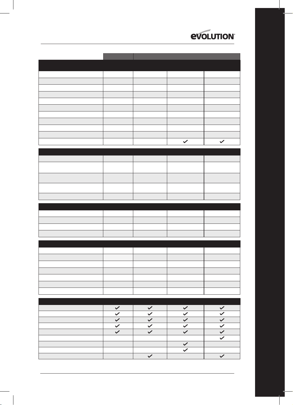
95
www.evolutionpowertools.com
ES
EE.UU.
CARACTERÍSTICAS TÉCNICAS
DE LA MÁQUINA
R165CCSL
R185CCS R185CCSX R185CCSX+
N.º de modelo:
026-0004
027-0004 027-0004C 027-0004A
Motor UE (220-240V ~ 50 Hz)
Motor Reino Unido(110V ~ 50 Hz)
Motor EE.UU. (120V ~ 60Hz)
10A
15A 15A 15A
Velocidad sin carga (220-240v)
Velocidad sin carga (110v & 120v)
3900 min
-1
/ rpm
3700 min
-1
/ rpm 3700 min
-1
/ rpm 3700 min
-1
/ rpm
Peso
9.5 lb
10,8 lb 11,2 lb 11,2 lb
Máx. ángulo de bisel de la cuchilla
45˚
60˚ 45˚ 45˚
Longitud del cable de corriente
10 ft
13ft 13ft 13ft
Tipo de base de la sierra circular
Pressed Steel Aluminio fundido Aluminio fundido Aluminio fundido
Compatible con la vía de corte
CAPACIDADES DE CORTE
R165CCSL
R185CCS R185CCSX R185CCSX+
Placa de acero dulce (Grosor máximo)
1/8"
1/4” 1/4” 1/4”
Sección de la caja de acero dulce
(Grosor máximo de la pared)
1/8”
1/4” 1/4” 1/4”
Grosor de corte máximo (0°)
2-3/32"
2-1/2”
2-1/2”
(2-5/16” anchura/vía)
2-1/2”
(2-5/16” anchura/vía)
Grosor de corte máximo (45°)
1-11/32"
1-9/16”
1-13/16”
(1-5/8” anchura/vía)
1-13/16”
(1-5/8” anchura/vía)
Grosor de corte máximo (60°) 1”
ESPECIFICACIONES DE LA HOJA
R165CCSL
R185CCS R185CCSX R185CCSX+
Diámetro de la hoja
Ø 6-1/2"
Ø 7-1/4” Ø 7-1/4” Ø 7-1/4”
Número de dientes
14
20 16 20
Diámetro de perforación
25/32"
25/32” 25/32” 25/32”
Ranura
1.7mm
1,7mm 1,7mm 1,7mm
DATOS DE RUIDO Y VIBRACIÓN
R165CCSL
R185CCS R185CCSX R185CCSX+
Nivel de presión acústica L
pa
92,4dB(A) K:3dB(A)
97,3dB(A) K=3 dB(A) 97,3dB(A) K=3 dB(A) 97,3dB(A) K=3 dB(A)
Nivel de potencia acústica L
wa
103,4dB(A) K:3dB(A)
105,3dB(A) K=3 dB(A) 105,3dB(A) K=3 dB(A) 105,3dB(A) K=3 dB(A)
Vibración mango principal (serrado de madera) a
h,w
= 2,747m/s
2
a
h,w
= 3,347m/s
2
a
h,w
= 3,347m/s
2
a
h,w
= 3,347m/s
2
Vibración mango adicional (serrado de madera) a
h,w
= 2,619m/s
2
a
h,w
= 3,119m/s
2
a
h,w
= 3,119m/s
2
a
h,w
= 3,119m/s
2
Vibración mango principal (serrado de metal) a
h,M
= 2,302m/s
2
a
h,M
= 3,572m/s
2
a
h,M
= 3,572m/s
2
a
h,M
= 3,572m/s
2
Vibración mango adicional (serrado de metal) a
h,M
= 2,239m/s
2
a
h,M
= 3,241m/s
2
a
h,M
= 3,241m/s
2
a
h,M
= 3,241m/s
2
Uncertainty K
1,5m/s
2
1,5m/s
2
1,5m/s
2
1,5m/s
2
ELEMENTOS SUMINISTRADOS
R165CCSL
R185CCS R185CCSX R185CCSX+
Hoja TCT multimaterial
Llave hexagonal (cambio de hoja)
Carril guía paralelo
Adaptador del puerto de polvo
Conector de la manguera de polvo
Estuche de transporte
Vía de corte (340mm x3)
Barra de conector y tornillos (x4)
Luz LED
ESPECIFICACIONES

96
www.evolutionpowertools.com
Reino Unido / UE / AUS
R165CCSL R185CCS R185CCSX R185CCSX+
026-0001 / 026-0002 /
026-0003
027-0001C /
027-0002C / 027-0003C
027-0001 /
027-0002 / 027-0003
027-0001A /
027-0002A / 027-0003A
1200W 1600W 1600W 1600W
1200W 1600W 1600W 1600W
3700 min
-1
/ rpm 3900 min
-1
/ rpm 3900 min
-1
/ rpm 3900 min
-1
/ rpm
3700 min
-1
/ rpm 3700 min
-1
/ rpm 3700 min
-1
/ rpm 3700 min
-1
/ rpm
4,3 kg 4,9 kg 5,1 kg 5,1 kg
45˚ 60˚ 45˚ 45˚
3m 3m 3m 4m
Acero prensado Aluminio fundido Aluminio fundido Aluminio fundido
R165CCSL R185CCS R185CCSX R185CCSX+
3mm 6mm 3mm 6mm
3mm 6mm 3mm 6mm
53mm 64mm
64mm
(59mm con vía)
64mm
(59mm con vía)
34mm 40mm
47mm
(42mm con vía)
47mm
(42mm con vía)
24mm
R165CCSL R185CCS R185CCSX R185CCSX+
Ø 165mm Ø 185mm Ø 185mm Ø 185mm
14 20 16 20
20mm 20mm 20mm 20mm
1,7mm 1,7mm 1,7mm 1,7mm
R165CCSL R185CCS R185CCSX R185CCSX+
92,4dB(A) K:3dB(A) 97,3dB(A) K=3 dB(A) 97,3dB(A) K=3 dB(A) 97,3dB(A) K=3 dB(A)
103,4dB(A) K:3dB(A) 105,3dB(A) K=3 dB(A) 105,3dB(A) K=3 dB(A) 105,3dB(A) K=3 dB(A)
a
h,w
= 2,747m/s
2
a
h,w
= 3,347m/s
2
a
h,w
= 3,347m/s
2
a
h,w
= 3,347m/s
2
a
h,w
= 2,619m/s
2
a
h,w
= 3,119m/s
2
a
h,w
= 3,119m/s
2
a
h,w
= 3,119m/s
2
a
h,M
= 2,302m/s
2
a
h,M
= 3,572m/s
2
a
h,M
= 3,572m/s
2
a
h,M
= 3,572m/s
2
a
h,M
= 2,239m/s
2
a
h,M
= 3,241m/s
2
a
h,M
= 3,241m/s
2
a
h,M
= 3,241m/s
2
1,5m/s
2
1,5m/s
2
1,5m/s
2
1,5m/s
2
R165CCSL R185CCS R185CCSX R185CCSX+

97
www.evolutionpowertools.com
ES
VIBRACIONES
(1.5) Nota: La medición de la vibración se hizo en
condiciones normales de acuerdo con la norma
EN 62841-1: 2015, EN 62841-2-5: 2014
Advertencia: ¡Utilice protección auditiva!
El valor total de vibración citado se ha medido
según el método normal de examen y puede
usarse para comparar una herramienta con otra.
El valor total de vibración citado también
puede usarse en la evaluación preliminar de la
exposición humana.
(1.6) ADVERTENCIA: Al utilizar esta máquina, el
operador puede estar expuesto a altos niveles de
vibración transmitidos a la mano y al brazo.
Es posible que el operador pueda desarrollar
la «enfermedad de los dedos blancos» debido
a la vibración (síndrome de Raynaud). Esta
enfermedad puede reducir la sensibilidad de
la mano a la temperatura, así como producir
entumecimiento general. Los usuarios que
utilicen esta máquina de manera prolongada
o regular deben vigilar de cerca el estado de
sus manos y dedos. Si aparece alguno de los
síntomas, busque atención médica inmediata.
• La medición y la evaluación de la exposición
humana a las vibraciones transmitidas por la
mano en el lugar de trabajo se indican en:
EN 62841-1 y EN 62841-2-5
• Muchos factores pueden influir en el nivel de
vibración real durante el funcionamiento, p. ej.
el estado y la orientación de las superficies de
trabajo, y el tipo y el estado de la máquina que
se está usando. Antes de cada uso, se deben
evaluar dichos factores y adoptar prácticas
de trabajo adecuadas donde sea posible. La
gestión de estos factores puede ayudar a
reducir los efectos de la vibración:
Manipulación
• Manipule la máquina con cuidado,
permitiendo que esta haga el trabajo.
• Evite un esfuerzo físico excesivo en cualquiera
de los controles de las máquinas.
• Tenga en cuenta su seguridad y estabilidad,
así como la orientación de la máquina durante
su uso.
Superficie de trabajo
• Tenga en cuenta el material de la superficie de
trabajo, su estado, densidad, resistencia,
rigidez y orientación.
ADVERTENCIA: la emisión de vibraciones al usar
la herramienta eléctrica puede variar del valor
total citado dependiendo de la manera en la que
se use la herramienta.
La necesidad de identificar medidas de
seguridad y de proteger al operador se basa
en una estimación de la exposición en las
condiciones reales de uso (teniendo en cuenta
todas las partes del ciclo operativo, como las
veces que se desconecta la máquina, cuándo
está en reposo, además del tiempo que está
funcionando de forma continuada).
(1.7 ) ETIQUETAS Y SÍMBOLOS
ADVERTENCIA: no utilice la máquina
si faltan la advertencia y/o las etiquetas de
instrucciones, o si están dañadas. Póngase en
contacto con Evolution Power Tools para sustituir
las etiquetas.
Nota: todos o algunos de los siguientes símbolos
pueden aparecer en el manual o en el producto.
98
www.evolutionpowertools.com
(1.8)
Símbolo Descripción
V
Voltios
A
Amperios
HZ
Hercios
Min
-1
/ RPM
Velocidad
~
Corriente alterna
n
o
Velocidad sin carga
Utilice gafas protectoras
Utilice protección auditiva
Utilice protección contra el polvo
Lea las instrucciones
Doble aislamiento
Certificado CE
Certificado ETL
Residuos de Aparatos
Eléctricos y Electrónicos
Triman: recogida y reciclado
de residuos
Advertencia
(RCM) Marca de cumplimiento de la
normativa para aparatos eléctricos
y electrónicos. Norma de Australia/
Nueva Zelanda
(1.9) USO PREVISTO
DE ESTA HERRAMIENTA ELÉCTRICA
ADVERTENCIA: Este producto es una sierra
circular de uso manual y ha sido diseñada para
usarse con hojas especiales de Evolution. Use
solamente accesorios diseñados para el uso
de esta máquina y/o aquellos recomendados
específicamente por Evolution Power Tools Ltd.
Equipada con una hoja adecuada,
esta máquina puede cortar:
Acero dulce, aluminio, madera
Nota: el corte de acero galvanizado puede
reducir la duración de la hoja.
(1.10) USO PROHIBIDO
DE ESTA HERRAMIENTA ELÉCTRICA
ADVERTENCIA: Este producto es una sierra
circular de uso manual y debe usarse solo como
tal. No debe ser modificada de ninguna manera
ni usada para alimentar ningún otro equipo,
tampoco debe llevar ningún otro accesorio que
no se nombre en el manual de instrucciones.
(1.11) ADVERTENCIA: Esta máquina no está
diseñada para ser utilizada por personas (niños
incluidos) con discapacidad psíquica, sensorial
o mental, o con falta de experiencia y
conocimiento, a no ser que hayan sido
supervisadas o instruidas en el uso seguro
de la máquina por una persona responsable
de su seguridad y competente en el uso seguro
de esta.
Debe supervisarse a los niños para asegurarse
de que no tienen acceso a la máquina ni
pueden jugar con ella.
(1.12) SEGURIDAD ELÉCTRICA
Esta máquina está equipada con el enchufe
moldeado y el cable de red correctos para el
mercado designado. Si el cable de suministro se
daña, el fabricante o su agente de servicios debe
reemplazarlo por un cable o ensamblaje especial.
(1.13) USO EN EXTERIORES
ADVERTENCIA: Para su protección, si va
a usar esta herramienta en exteriores no
debe exponerla a la lluvia o usarla en lugares
húmedos. No coloque la herramienta en
superficies húmedas. Si es posible, use un banco
de trabajo limpio y seco. Para obtener una mayor
protección, utilice un dispositivo de corriente
residual que interrumpa el suministro si la
corriente de fuga a tierra es superior a 30 mA
durante 30 ms. Revise siempre el funcionamiento

99
www.evolutionpowertools.com
ES
del dispositivo de corriente residual antes de usar
la máquina.
Si es necesario un alargador, debe ser de un tipo
adecuado para exteriores y etiquetado para tal fin.
Se deben seguir las instrucciones de los
fabricantes al utilizar un alargador.
(2.1) INSTRUCCIONES GENERALES DE
SEGURIDAD
(Estas instrucciones generales de seguridad para
herramientas eléctricas son las que se especifican
en las normas
EN 62841-1: 2015
).
ADVERTENCIA: lea todas las advertencias e
instrucciones de seguridad. El incumplimiento
de las advertencias e instrucciones puede
provocar una descarga eléctrica, incendios y/o
lesiones graves. Guarde todas las advertencias
e instrucciones para poder consultarlas en el
futuro. El término "herramienta eléctrica" de
las advertencias se refiere a la herramienta
alimentada por la red de alimentación (con
cable) o con baterías (inalámbrica).
(2.2) 1) Advertencias generales de seguridad
de la herramienta eléctrica
[seguridad en el área de trabajo]
a) Mantenga la zona de trabajo limpia y bien
iluminada. Se podrían producir accidentes en
zonas desordenadas u oscuras.
b) No utilice las herramientas eléctricas en
atmósferas explosivas, como en presencia
de líquidos inflamables, gases o polvo. Las
herramientas eléctricas producen chispas que
pueden incendiar el polvo o los gases.
c) Mantenga a los niños y transeúntes
alejados cuando utilice una herramienta
eléctrica. Las distracciones pueden hacerle
perder el control.
(2.3) 2) Advertencias generales de seguridad
de la herramienta eléctrica [Seguridad
eléctrica]
a) Los enchufes de la herramienta eléctrica
deben corresponderse con las tomas de
corriente. No modifique el enchufe de ningún
modo. No utilice adaptadores de enchufe con
las herramientas eléctricas conectadas a tierra.
Si las tomas de corriente y los enchufes respectivos
no se modifican, se reduce el riesgo de descarga
eléctrica.
b) Evite el contacto corporal con superficies
conectadas a tierra tales como tuberías,
radiadores, estufas y refrigeradores. El riesgo
de descarga eléctrica aumenta si su cuerpo está
conectado a tierra.
c) No exponga las herramientas eléctricas a la
lluvia o a la humedad. La entrada de agua en
una herramienta eléctrica aumentará el riesgo de
descarga eléctrica.
d) No haga mal uso del cable. Nunca use el
cable para transportar, tirar o desenchufar la
herramienta eléctrica. Mantenga el cable lejos
del calor, el aceite, las esquinas cortantes o
piezas móviles. Los cables dañados o enredados
aumentan el riesgo de descarga eléctrica.
e) Cuando trabaje con una herramienta
eléctrica en exteriores, use un alargador
adecuado para uso en exteriores. El uso de un
cable adecuado para uso en exteriores reduce el
riesgo de descarga eléctrica.
f) Si usa una herramienta eléctrica en un lugar
húmedo, es necesario utilizar una toma de
corriente residual (RCD) protegida.
El uso de un dispositivo de corriente residual
reduce el riesgo de descarga eléctrica.
(2.4) 3) Advertencias generales de seguridad
de la herramienta eléctrica [Seguridad
personal].
a) Manténgase alerta, tenga cuidado con lo
que hace y use el sentido común al utilizar una
herramienta eléctrica. No utilice una herramienta
eléctrica cuando esté cansado o bajo la influencia
de drogas, alcohol o medicación. Un momento de
distracción mientras utiliza herramientas eléctricas
puede ocasionar lesiones personales graves.
b) Utilice el equipo de protección individual.
Utilice siempre protección para los ojos. El uso
del equipo de seguridad, como máscaras para el
polvo, calzado antideslizante, casco o protección
auditiva para las condiciones adecuadas reducirá
las lesiones personales.
c) Evite el encendido accidental. Asegúrese de
que el interruptor está en la posición off antes
de conectar a la fuente de alimentación y/o a las
baterías, o de coger o transportar la herramienta.
Transportar herramientas eléctricas con el dedo
sobre el interruptor o enchufar herramientas
eléctricas con el interruptor encendido
puede propiciar accidentes.
d) Quite las llaves de ajuste o llaves inglesas
del perno de la hoja antes de encender la
herramienta eléctrica. Una llave, como una llave
inglesa, colocada en una pieza giratoria de la
herramienta eléctrica puede ocasionar lesiones
personales.
e) No se extralimite. Mantenga la postura y
el equilibrio en todo momento. Esto permitirá
un mejor control de la herramienta eléctrica en
situaciones inesperadas.
f) Vístase de manera adecuada. No use ropa
suelta ni joyas. Mantenga el pelo, la ropa y los

100
www.evolutionpowertools.com
guantes alejados de las piezas móviles. Las joyas,
la ropa holgada y el cabello largo pueden quedar
atrapados en las piezas móviles.
g) Si se proporcionan dispositivos para la
conexión de unidades de extracción y recogida
de polvo, asegúrese de que están conectadas
y de que se usan de forma adecuada. El uso
de estos dispositivos puede reducir los riesgos
derivados del polvo.
h) El hecho de que esté familiarizado gracias al
uso frecuente de las herramientas no debería
hacer que se vuelva complaciente ni que ignore
los principios de seguridad de la herramienta.
Una acción negligente puede provocar lesiones
graves en una milésima de segundo.
(2.5) 4) Advertencias generales de seguridad
de la herramienta eléctrica [Uso y cuidado de
la herramienta eléctrica].
a) No fuerce la herramienta eléctrica. Utilice
la herramienta correcta para su aplicación. La
herramienta correcta realizará el trabajo de una
forma más precisa y segura al ritmo para el que ha
sido diseñada.
b) No utilice la herramienta eléctrica si el
interruptor no se enciende ni se apaga. Una
herramienta eléctrica que no se pueda controlar
con el interruptor es peligrosa y se debe reparar.
c) Desconecte la herramienta eléctrica de la
fuente de alimentación de la herramienta
eléctrica antes de efectuar ajustes, cambiar
accesorios o almacenar las herramientas
eléctricas. Este tipo de medidas de seguridad
preventivas reducen el riesgo de que la
herramienta eléctrica se inicie accidentalmente.
d) Guarde las herramientas eléctricas fuera del
alcance de los niños y no permita que personas
que no estén familiarizadas con la herramienta
eléctrica o estas instrucciones la usen. Las
herramientas eléctricas son peligrosas en manos
de personas inexpertas.
e) Realice un mantenimiento de las
herramientas eléctricas. Verifique la alineación
y fijación de las piezas móviles, la rotura de
las piezas móviles y cualquier otra condición
que pueda afectar al funcionamiento de
las herramientas eléctricas. Si está dañada,
repare la herramienta eléctrica antes de usarla.
Muchos accidentes se producen debido a un
mantenimiento deficiente de las herramientas
eléctricas.
f) Mantenga las herramientas de corte limpias
y afiladas.
Las herramientas de corte con buen
mantenimiento y bordes de corte afilados son
menos propensas a trabarse y son más fáciles de
controlar.
g) Use la herramienta eléctrica, accesorios y
útiles, etc. de acuerdo con estas instrucciones
y teniendo en cuenta las condiciones de
funcionamiento y el trabajo que se va a
realizar. El uso de la herramienta eléctrica para
operaciones diferentes a las previstas
podría provocar una situación peligrosa.
h)Mantenga los mangos y las superficies de
agarre secos y libres de aceite y grasa. Los
mangos y superficies de agarre resbaladizos
no permiten un manejo y control seguros de la
herramienta en situaciones inesperadas.
(2.6) 5) Advertencias generales de seguridad
de la herramienta eléctrica
Advertencias de seguridad [Servicio]
a) Lleve la herramienta eléctrica a reparar a
un experto cualificado que utilice solo piezas
de repuesto originales. Esto garantizará que se
mantenga la seguridad de la herramienta eléctrica
correctamente.
(2.7) CONSEJOS PARA SU SALUD
ADVERTENCIA: al utilizar esta máquina
se pueden producir partículas de polvo. En
ocasiones, según los materiales con los que
trabaje, este polvo puede ser especialmente
perjudicial. Si sospecha que la pintura de la
superficie del material que desea cortar contiene
plomo, busque ayuda profesional. No intente
quitar pintura a base de plomo. Solamente un
profesional debería hacerlo.
Una vez que el polvo se ha depositado en una
superficie, el contacto de la mano con la boca
puede llevar a la ingestión de plomo. Incluso
la exposición a niveles bajos de plomo puede
causar daños irreversibles en el cerebro y el
sistema nervioso. Los niños y los nonatos son
especialmente vulnerables.
Se recomienda que considere el riesgo asociado
a los materiales con los que trabaja para reducir
el riesgo de exposición.
Algunos materiales pueden producir polvo
dañino para su salud. Recomendamos el uso de
mascarillas reguladas con filtros reemplazables
cuando use esta máquina.
Siempre debe:
• Trabajar en una zona bien ventilada.
• Trabajar con un equipo de seguridad
aprobado, como mascarillas para el polvo que
hayan sido diseñadas especialmente para
filtrar partículas microscópicas.
(2.8) ADVERTENCIA: el manejo de cualquier
herramienta eléctrica puede provocar que se
lancen objetos externos contra los ojos que

101
www.evolutionpowertools.com
ES
pueden ocasionar daños graves en los mismos.
Antes de empezar a utilizar una herramienta
eléctrica, póngase siempre gafas con protección
lateral o una máscara que cubra toda la cara
cuando sea necesario.
INSTRUCCIONES DE SEGURIDAD PARA
TODAS LAS SIERRAS
[Procedimientos de corte]
a) PELIGRO: Mantenga las manos lejos de la
zona de corte y de la hoja. Mantenga la otra
mano en el mango adicional o en la carcasa
del motor. Si sujeta la sierra con las dos manos,
no se cortará con la hoja.
b) No toque por debajo de la pieza de trabajo.
La protección no puede protegerlo de la hoja
bajo la pieza de trabajo.
c) Ajuste la profundidad del corte al grosor
de la pieza de trabajo. Debajo de la pieza de
trabajo debe ser visible menos de un diente de
la hoja.
d) No sostenga nunca la pieza de trabajo en
la mano ni sobre las piernas cuando corta.
Asegure la pieza de trabajo a una plataforma
estable. Es importante apoyar la pieza de
forma adecuada para minimizar la exposición
del cuerpo, las posibilidades de que la hoja se
atasque o la pérdida de control.
e) Sostenga la herramienta eléctrica por
superficies de adherencia aisladas cuando
realice una operación en la que la herramienta
de corte pueda entrar en contacto con
cableado no visible o su propio cable. El
contacto con un cable «con corriente» también
hará que las partes metálicas expuestas de
la herramienta eléctrica estén sometidas
a«corriente» y podrían electrocutar al operario.
f) Cuando corte, use siempre un tope-guía o
un carril guía. Esto mejora la precisión del corte
y reduce la posibilidad de que la hoja se atasque.
g) Use siempre hojas con el tamaño y forma
del orificio del eje correctos (diamante frente
a circular). Las hojas que no encajan con el
equipo de montaje de la sierra funcionan de
forma descentrada, provocando pérdida de
control.
h) No utilice arandelas o tornillos dañados o
inapropiados. Los tornillos y arandelas están
especialmente diseñados para su sierra, para
conseguir un rendimiento y seguridad óptimos.
(3.2) [Causas de contragolpes y advertencias
relacionadas]
Un contragolpe es una reacción inesperada
de una hoja de sierra pillada, atascada o mal
alineada que provoca que la sierra se dispare de
forma descontrolada de la pieza de trabajo hacia
el operario.
Si la hoja está atascada o fijada firmemente al
penetrar el corte, la hoja se bloquea y la reacción
del motor mueve la unidad rápidamente hacia
atrás en dirección al operario.
Si la hoja se tuerce o se desajusta durante el
corte, los dientes del borde posterior de la hoja
pueden penetrar en la superficie superior de la
madera, provocando que la hoja se salga de la
ranura y se precipite hacia el operario.
(3.3) El contragolpe es el resultado de un
mal uso de la sierra y/o de procedimientos o
condiciones de un uso inadecuado, y puede
evitarse tomando las debidas precauciones que
se indican a continuación.
a) Mantenga una sujeción firme con ambas
manos en la sierra y posicione los brazos para
resistir la fuerza del contragolpe. Colóquese
a un lado de la hoja; no se posicione en la
trayectoria de la hoja. El contragolpe puede
provocar que la sierra salga disparada hacia atrás,
pero la fuerza del contragolpe puede controlarse
por el operario si se toman las medidas necesarias.
b) Si la hoja se empieza a atascar o si se
interrumpe el corte por cualquier razón,
suelte el gatillo y mantenga la sierra firme
en el material hasta que la hoja se pare por
completo. Nunca intente retirar la sierra de la
pieza o tirar de la sierra hacia atrás mientras
la hoja continúe en movimiento o podría
producirse un contragolpe. Investigue y tome
las medidas necesarias para eliminar la causa del
atascamiento de la hoja.
c) Cuando vuelva a encender la sierra en la
pieza de trabajo, centre la hoja de la sierra en
la ranura y compruebe que los dientes de la
hoja no están atascados en el material. Si una
sierra se atasca, podría soltarse o provocar un
contragolpe desde la pieza de trabajo cuando
vuelva a encender la sierra.
d) No use hojas desafiladas o dañadas. Las
hojas desafiladas o mal ajustadas producen una
ranura estrecha, causando una fricción excesiva,
atascamiento de la hoja y contragolpes.
e) Las palancas de bloqueo del ajuste de
profundidad de la hoja y del bisel deben estar
firmes y seguras antes de realizar un corte.
Si el ajuste de la hoja cambia durante el corte,
podría causar su atascamiento y un contragolpe.
f) Las palancas de bloqueo del ajuste de
profundidad de la hoja y del bisel deben estar
firmes y seguras antes de realizar el corte. Si el
ajuste de la hoja cambia durante el corte podría
causar su atascamiento y un contragolpe.
g) Extreme las precauciones cuando realice
un corte en una pared u otras zonas ciegas.
La hoja saliente puede cortar objetos que
provoquen un contragolpe.

102
www.evolutionpowertools.com
FUNCIÓN DE PROTECCIÓN INFERIOR
a) Compruebe que ha cerrado correctamente
la protección inferior antes de cada uso. No
utilice la sierra si la protección inferior no
se mueve libremente y se cierra de forma
instantánea. Nunca fije o sujete la protección
inferior en la posición de apertura. Si la sierra
se cae accidentalmente, la protección inferior
podría doblarse. Suba la protección inferior con
el tirador retráctil y asegúrese de que se mueve
libremente y no toca la hoja o ninguna otra parte
en cualquier ángulo o profundidad de corte.
b) Compruebe el funcionamiento del muelle
de la protección inferior. Si la protección y el
muelle no funcionan correctamente, deben
ser arreglados antes de usar la máquina. La
protección puede funcionar lentamente debido
a que tenga partes dañadas, restos pegajosos o
una acumulación de desechos.
c) La protección inferior solo puede retraerse
manualmente para cortes especiales, como
«cortes de inmersión» o «cortes compuestos».
Suba la protección inferior con el tirador
retráctil y, en cuanto la hoja toque el material,
suelte la protección inferior. Para cualquier
otro corte, la protección inferior debe funcionar
automáticamente.
d) Asegúrese siempre de que la protección
inferior cubre la hoja antes de posar la
sierra en un banco o en el suelo. Una hoja
en movimiento y desprotegida hará que la
sierra vaya hacia atrás, cortando todo lo que
encuentre a su paso. Tenga en cuenta el tiempo
que necesita la hoja para pararse una vez
desconectada.
INSTRUCCIONES ADICIONALES
DE SEGURIDAD PARA SIERRAS
CIRCULARES
a) No use hojas de sierra de acero rápido (HSS).
b) Inspeccione la máquina y la hoja
antes de cada uso. No utilice hojas deformadas,
partidas, desgastadas o dañadas de alguna
manera.
c) Nunca utilice la sierra sin su sistema de
protección original. No bloquee la protección
móvil en la posición de apertura. Asegúrese de
que puede mover la protección libremente y sin
interferencias.
d) Solamente use hojas que cumplan con las
características especificadas en este manual.
Antes de usar accesorios, compare siempre
las RPM máximas permitidas del accesorio con
las RPM de la máquina.
e) No use discos abrasivos.
f) Use únicamente diámetros de hoja de
conformidad con los marcados.
(3.4) ADVERTENCIA: Si faltan piezas, no utilice
la máquina hasta que estas se reemplacen. No
seguir esta indicación puede causar graves daños
personales.
(4.1) PRIMEROS PASOS - DESEMBALAJE
Precaución: este paquete contiene objetos
punzantes. Tenga cuidado al desembalarlo.
Saque la máquina del embalaje junto con los
accesorios suministrados. Revise con atención
para comprobar que la máquina está en
buenas condiciones y que cuenta con todos los
accesorios que se enumeran en este manual.
Asegúrese también de que todos los accesorios
estén completos.
Si falta alguna de las piezas, la máquina y los
accesorios se deben devolver juntos en su
embalaje original a su distribuidor.
No tire el embalaje, guárdelo durante todo el
período de garantía. Sea respetuoso con el
medio ambiente cuanto tire el embalaje. Si fuese
posible, recíclelo.
No deje que los niños jueguen con las bolsas de
plástico vacías debido al riesgo de asfixia.
(4.3) MANUALES DE INSTRUCCIONES
DE EVOLUTION
Cada producto de Evolution Power Tools incluye
un manual de instrucciones.
Cada manual dedicado se ha elaborado y
diseñado cuidadosamente para proporcionar
información útil y fácilmente accesible acerca del
uso seguro, el cuidado y el mantenimiento del
producto. La consulta de la información incluida
en el manual permitirá al operario aprovechar de
forma plena y segura el potencial de la máquina.
La política de Evolution de mejora continua
del producto puede significar que, en muchas
ocasiones, los contenidos de un manual pueden
no reflejar completamente las últimas mejoras
o actualizaciones que se han incorporado en un
producto particular. Las mejoras/actualizaciones
de las especificaciones de un producto podrían
ser consecuencia de avances tecnológicos o
cambios en el marco legislativo del país de
recepción, etc.
Si no está seguro acerca de algún aspecto
del uso, el cuidado o el mantenimiento de
un producto Evolution, póngase en contacto
con la asistencia técnica pertinente, la cual
le proporcionará información actualizada y
consejos adicionales.
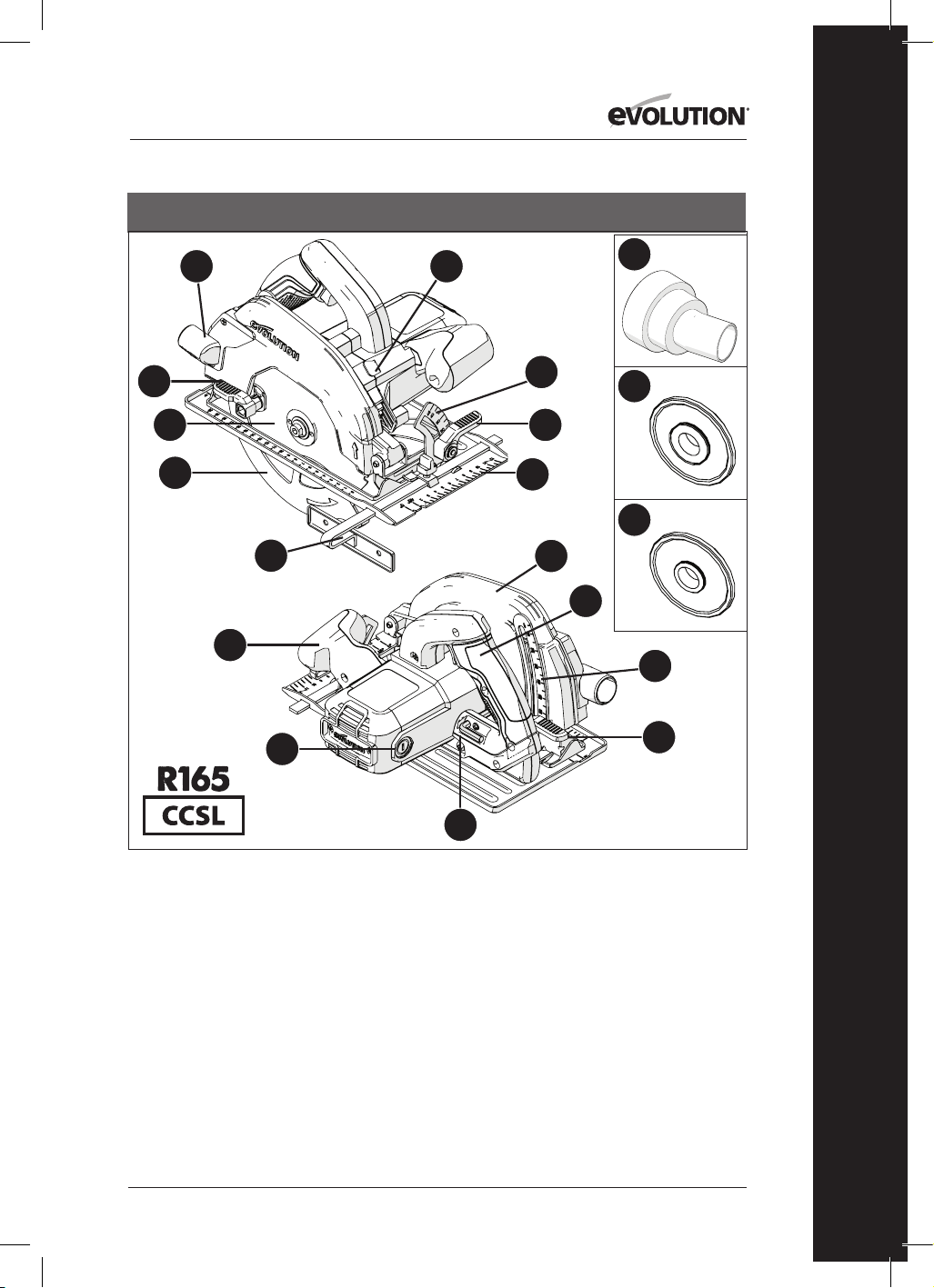
103
www.evolutionpowertools.com
ES
1. PUERTO DE EXPULSIÓN DEL MATERIAL DE CORTE
2. PALANCA DE PULGAR
3. HOJA TCT MULTIMATERIAL
4. PROTECCIÓN INFERIOR DE LA HOJA
5. CARRIL GUÍA PARALELO
6. MANGO FRONTAL ERGONÓMICO
7. ESCOBILLAS DE CARBONO
8. LLAVE HEXAGONAL DE 8MM (CAMBIO DE HOJA)
9. PALANCA DE BLOQUEO DEL AJUSTE DE PROFUNDIDAD
10. ESCALA DE PROFUNDIDAD
11. MANGO TRASERO
12. PROTECCIÓN SUPERIOR DE LA HOJA
13. PLACA BASE DE PRECISIÓN DISEÑADA
14. PALANCA DE PULGAR
15. ESCALA DEL TRANSPORTADOR DE ÁNGULOS
16. BOTÓN DEL SEGURO DEL EJE
17. CONECTOR DEL PUERTO DE POLVO
18. BORDE INTERIOR DE LA HOJA 25/32”
19. BORDE INTERIOR DE LA HOJA 5/8”
EE.UU.
13
15
4
14
5
1
3
8
9
10
11
6
7
2
16
12
17
18
19
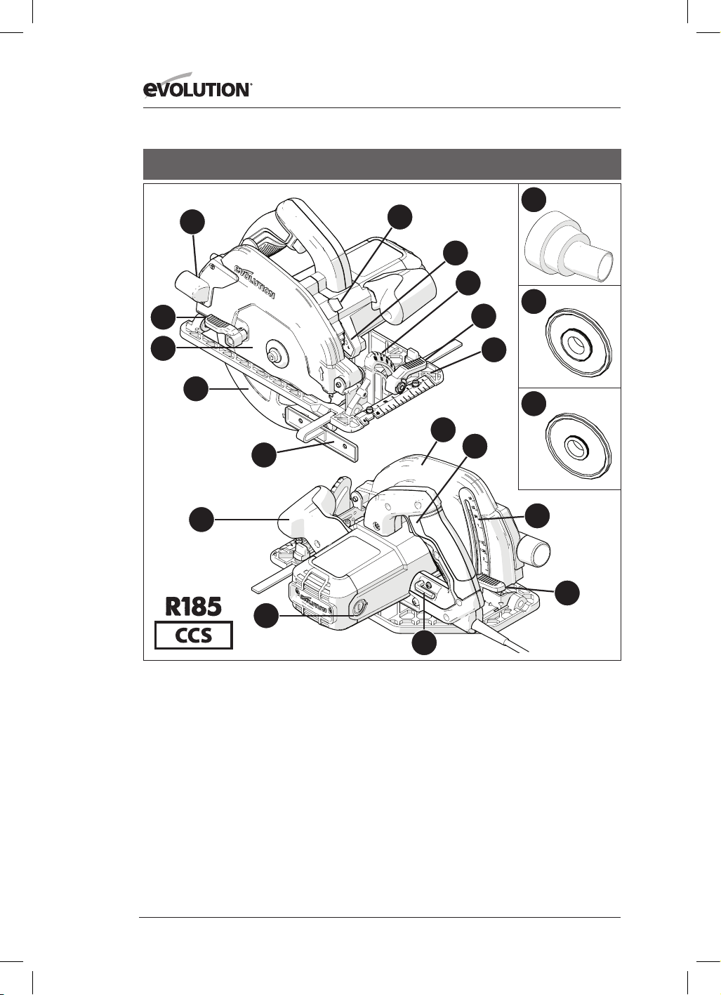
104
www.evolutionpowertools.com
EE.UU.
1. PUERTO DE EXPULSIÓN DEL MATERIAL DE CORTE
2. PALANCA DE PULGAR
3. HOJA TCT MULTIMATERIAL
4. PROTECCIÓN INFERIOR DE LA HOJA
5. CARRIL GUÍA PARALELO
6. MANGO FRONTAL ERGONÓMICO
7. ESCOBILLAS DE CARBONO
8. LLAVE HEXAGONAL DE 8MM (CAMBIO DE HOJA)
9. PALANCA DE BLOQUEO DEL AJUSTE DE PROFUNDIDAD
10. ESCALA DE PROFUNDIDAD
11. INTERRUPTOR ON/OFF DEL MANGO TRASERO
12. PROTECCIÓN SUPERIOR DE LA HOJA
13. PLACA BASE DE PRECISIÓN DISEÑADA
14. PALANCA DE PULGAR DE AJUSTE DEL BISEL
15. ESCALA DEL TRANSPORTADOR DE ÁNGULOS
16. BOTÓN DEL SEGURO DEL EJE
17. LUZ LED
18. CONECTOR DEL PUERTO DE POLVO
19. BORDE INTERIOR DE LA HOJA 25/32”
20. BORDE INTERIOR DE LA HOJA 5/8”
13
15
17
18
19
20
4
14
5
1
3
8
9
10
11
6
7
2
16
12
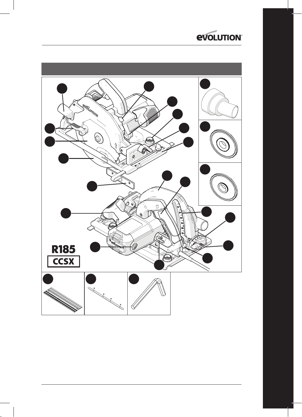
105
www.evolutionpowertools.com
ES
EE.UU.
1. PUERTO DE EXPULSIÓN DEL
MATERIAL DE CORTE
2. PALANCA DE PULGAR
3. HOJA TCT MULTIMATERIAL
4. PROTECCIÓN INFERIOR DE LA HOJA
5. CARRIL GUÍA PARALELO
6. MANGO FRONTAL ERGONÓMICO
7. ESCOBILLAS DE CARBONO
8. LLAVE HEXAGONAL DE 5/16”
(CAMBIO DE HOJA)
9. PALANCA DE BLOQUEO DEL AJUSTE
DE PROFUNDIDAD
10. ESCALA DE PROFUNDIDAD
11. INTERRUPTOR ON/OFF DEL MANGO
TRASERO
12. PROTECCIÓN SUPERIOR DE LA HOJA
13. PLACA BASE DE PRECISIÓN
DISEÑADA COMPATIBLE CON LA VÍA
14. PALANCA DE PULGAR
15. ESCALA DEL TRANSPORTADOR DE
ÁNGULOS TRASERO
16. BOTÓN DEL SEGURO DEL EJE
17. LUZ LED
18. CONECTOR DEL PUERTO DE POLVO
19. BORDE INTERIOR DE LA HOJA 25/32”
20. BORDE INTERIOR DE LA HOJA 5/8”
21. BOTONES DE GIRO DEL AJUSTE
DE VÍA
22. TORNILLO DE MARIPOSA DEL BISEL
TRASERO
23. 3x VÍAS DE 13-3/8”
24. 4x BARRAS DE CONECTOR DE VÍA
25. LLAVE HEXAGONAL DE 1/8”
13
21
15
17
18
19
20
4
14
5
1
3
8
9
10
22
11
6
7
2
16
12
23 24
25
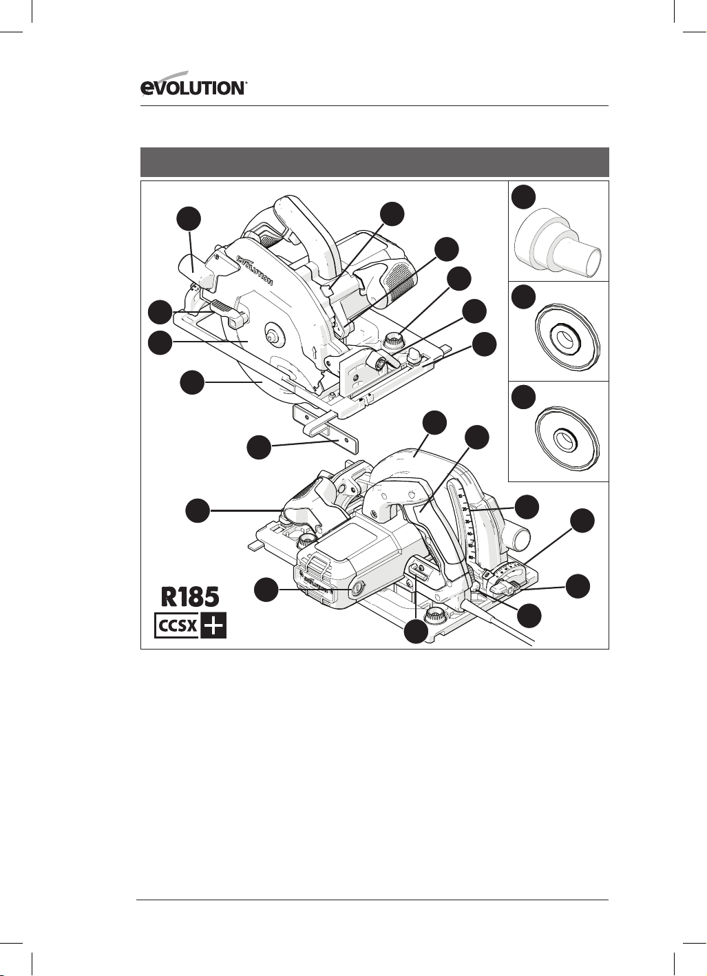
106
www.evolutionpowertools.com
EE.UU.
1. PUERTO DE EXPULSIÓN DEL MATERIAL DE CORTE
2. PALANCA DE PULGAR
3. HOJA TCT MULTIMATERIAL
4. PROTECCIÓN INFERIOR DE LA HOJA
5. CARRIL GUÍA PARALELO
6. MANGO FRONTAL ERGONÓMICO
7. ESCOBILLAS DE CARBONO
8. LLAVE HEXAGONAL DE 5/16” (CAMBIO DE HOJA)
9. PALANCA DE BLOQUEO DEL AJUSTE DE PROFUNDIDAD
10. ESCALA DE PROFUNDIDAD
11. INTERRUPTOR ON/OFF DEL MANGO TRASERO
12. PROTECCIÓN SUPERIOR DE LA HOJA
13. PLACA BASE DE PRECISIÓN DISEÑADA COMPATIBLE
CON LA VÍA
14. PALANCA DE PULGAR
15. ESCALA DEL TRANSPORTADOR DE ÁNGULOS TRASERO
16. BOTÓN DEL SEGURO DEL EJE
17. LUZ LED
18. CONECTOR DEL PUERTO DE POLVO
19. BORDE INTERIOR DE LA HOJA 25/32”
20. BORDE INTERIOR DE LA HOJA 5/8”
21. BOTONES DE GIRO DEL AJUSTE DE VÍA
22. TORNILLO DE MARIPOSA DEL BISEL TRASERO
13
21
15
17
18
19
20
4
14
5
1
3
8
9
10
22
11
6
7
2
16
12

107
www.evolutionpowertools.com
ES
13
15
4
14
5
1
3
8
9
10
11
6
7
2
16
12
1. PUERTO DE EXPULSIÓN DEL MATERIAL DE CORTE
2. PALANCA DE PULGAR
3. HOJA TCT MULTIMATERIAL
4. PROTECCIÓN INFERIOR DE LA HOJA
5. CARRIL GUÍA PARALELO
6. MANGO FRONTAL ERGONÓMICO
7. ESCOBILLAS DE CARBONO
8. LLAVE HEXAGONAL DE 8MM (CAMBIO DE HOJA)
9. PALANCA DE BLOQUEO DEL AJUSTE DE PROFUNDIDAD
10. ESCALA DE PROFUNDIDAD
11. EL MANGO TRASERO INCORPORA UN INTERRUPTOR ON/
OFF DE SEGURIDAD PARA ENCENDERLA
12. PROTECCIÓN SUPERIOR DE LA HOJA
13. PLACA BASE DE PRECISIÓN DISEÑADA
14. PALANCA DE PULGAR
15. ESCALA DEL TRANSPORTADOR DE ÁNGULOS
16. BOTÓN DEL SEGURO DEL EJE
REINO UNIDO / UE / AUS
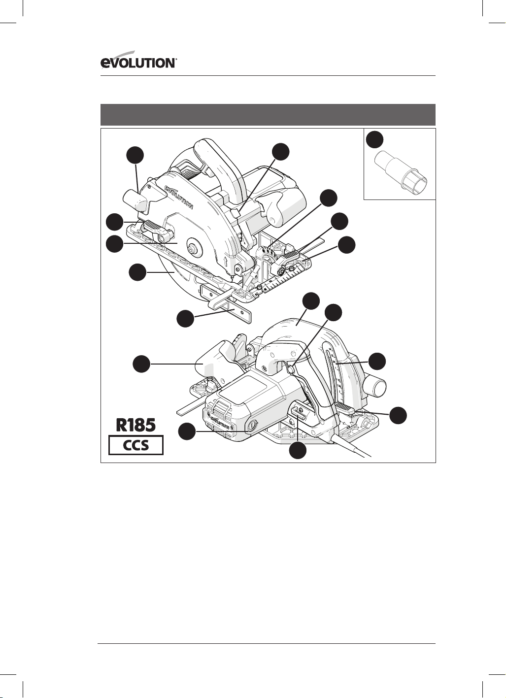
108
www.evolutionpowertools.com
1. PUERTO DE EXPULSIÓN DEL MATERIAL DE CORTE
2. PALANCA DE PULGAR
3. HOJA TCT MULTIMATERIAL
4. PROTECCIÓN INFERIOR DE LA HOJA
5. CARRIL GUÍA PARALELO
6. MANGO FRONTAL ERGONÓMICO
7. ESCOBILLAS DE CARBONO
8. LLAVE HEXAGONAL DE 8MM (CAMBIO DE HOJA)
9. PALANCA DE BLOQUEO DEL AJUSTE DE PROFUNDIDAD
10. ESCALA DE PROFUNDIDAD
11. EL MANGO TRASERO INCORPORA UN INTERRUPTOR ON/
OFF DE SEGURIDAD PARA ENCENDERLA
12. PROTECCIÓN SUPERIOR DE LA HOJA
13. PLACA BASE DE PRECISIÓN DISEÑADA
14. PALANCA DE PULGAR
15. ESCALA DEL TRANSPORTADOR DE ÁNGULOS
16. BOTÓN DEL SEGURO DEL EJE
17. CONECTOR DEL PUERTO DE POLVO
REINO UNIDO / UE
13
15
17
4
14
5
1
3
8
9
10
11
6
7
2
16
12
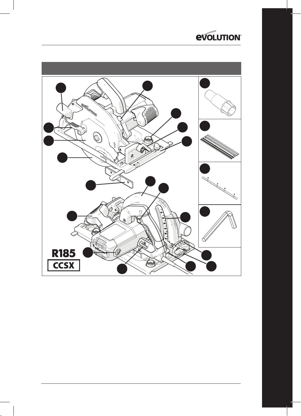
109
www.evolutionpowertools.com
ES
13
18
15
17
20
21
22
4
14
5
1
3
8
9
10
19
11
6
7
2
16
12
1. PUERTO DE EXPULSIÓN DEL MATERIAL DE CORTE
2. PALANCA DE PULGAR
3. HOJA TCT MULTIMATERIAL
4. PROTECCIÓN INFERIOR DE LA HOJA
5. CARRIL GUÍA PARALELO
6. MANGO FRONTAL ERGONÓMICO
7. ESCOBILLAS DE CARBONO
8. LLAVE HEXAGONAL DE 8MM (CAMBIO DE HOJA)
9. PALANCA DE BLOQUEO DEL AJUSTE DE PROFUNDIDAD
10. ESCALA DE PROFUNDIDAD
11. EL MANGO TRASERO INCORPORA UN INTERRUPTOR ON/
OFF DE SEGURIDAD PARA ENCENDERLA
12. PROTECCIÓN SUPERIOR DE LA HOJA
13. PLACA BASE DE PRECISIÓN DISEÑADA COMPATIBLE
CON LA VÍA
14. PALANCA DE PULGAR
15. ESCALA DEL TRANSPORTADOR DE ÁNGULOS TRASERO
16. BOTÓN DEL SEGURO DEL EJE
17. CONECTOR DEL PUERTO DE POLVO
18. BOTONES DE GIRO DEL AJUSTE DE VÍA
19. TORNILLO DE MARIPOSA DEL BISEL TRASERO
20. 3X VÍAS DE 340MM
21. 4X BARRAS DE CONECTOR DE VÍA
22. LLAVE HEXAGONAL DE 3MM
REINO UNIDO / UE

110
www.evolutionpowertools.com
REINO UNIDO / UE
1. PUERTO DE EXPULSIÓN DEL MATERIAL DE CORTE
2. PALANCA DE PULGAR
3. HOJA TCT MULTIMATERIAL
4. PROTECCIÓN INFERIOR DE LA HOJA
5. CARRIL GUÍA PARALELO
6. MANGO FRONTAL ERGONÓMICO
7. ESCOBILLAS DE CARBONO
8. LLAVE HEXAGONAL DE 8MM (CAMBIO DE HOJA)
9. PALANCA DE BLOQUEO DEL AJUSTE DE PROFUNDIDAD
10. ESCALA DE PROFUNDIDAD
11. EL MANGO TRASERO INCORPORA UN INTERRUPTOR ON/
OFF DE SEGURIDAD PARA ENCENDERLA
12. PROTECCIÓN SUPERIOR DE LA HOJA
13. PLACA BASE DE PRECISIÓN DISEÑADA COMPATIBLE
CON LA VÍA
14. PALANCA DE PULGAR
15. ESCALA DEL TRANSPORTADOR DE ÁNGULOS TRASERO
16. BOTÓN DEL SEGURO DEL EJE
17. CONECTOR DEL PUERTO DE POLVO
18. BOTONES DE GIRO DEL AJUSTE DE VÍA
19. TORNILLO DE MARIPOSA DEL BISEL TRASERO
13
18
15
17
4
14
5
1
3
8
9
10
19
11
6
7
2
16
12

111
www.evolutionpowertools.com
ES
Fig. 3Fig. 2
Fig. 4
Fig. 1
Fig. 8
Fig. 6Fig. 5
Fig. 9
Fig. 10
Fig. 7a Fig. 7b Fig. 7c

112
www.evolutionpowertools.com
Fig. 11
Fig. 12
Fig. 13
Fig. 14
Fig. 15
Fig. 16
Fig. 17 Fig. 18
Fig. 21Fig. 20
Fig. 19
Fig. 22
1 -2mm

113
www.evolutionpowertools.com
ES
Fig. 27Fig. 26
Fig. 25
Fig. 30 Fig. 31
Fig. 34
Fig. 24Fig. 23
Conector del puerto de
polvo EE.UU.
Conector del puerto de
polvo UE
Fig. 28
Fig. 29
Fig. 32 Fig. 33

114
www.evolutionpowertools.com
(10) PREPARACIÓN
ADVERTENCIA: Desconecte siempre la máquina
de la alimentación antes de realizar ningún ajuste.
Nota: Estas máquinas están equipadas con un
cable de alimentación y un enchufe aprobados
para el país de uso previsto. No altere ni modifique
el cable de alimentación.
(10.1) INSTALAR O DESMONTAR
UNA HOJA
ADVERTENCIA: Utilice solo hojas Evolution
originales (o aquellas aprobadas por Evolution
Power Tools) que hayan sido diseñadas para estas
máquinas. Asegúrese de que la velocidad máxima
de la hoja es compatible con la máquina. Realice
esta operación tan solo cuando la máquina esté
desconectada de la alimentación.
Nota: se recomienda que el operario lleve guantes
protectores cuando manipule la hoja durante
la instalación o cuando cambie la hoja de la
máquina.
• Localice la llave hexagonal de cambio de hoja
suministrada, que se encuentra en la instalación
de almacenamiento de a bordo (situada de
forma similar en todas las máquinas). (Fig. 1)
• Coloque la sierra en una superficie nivelada y
segura.
Nota: Con cuidado, todas las máquinas se pueden
equilibrar en el extremo plano de la carcasa del
motor, (Fig. 2) haciendo que el acceso a la hoja y a
las fijaciones de las hojas sea muy cómodo.
• Localice el botón del seguro del eje de la
máquina (que está situado de forma similar
en todas las máquinas). Bloquee el eje de la
máquina activando el botón del seguro del eje.
(Fig. 3).
Nota: Girar la hoja despacio manualmente,
mientras se presiona ligeramente el botón del
seguro del eje, ayudará a activar el seguro del eje.
• Con la llave hexagonal suministrada, afloje y
retire el tornillo de cabeza hueca del eje, las
fijaciones asociadas y el borde exterior de la
hoja. (Fig. 4)
Nota: El tornillo de cabeza hueca del eje está
equipado con una rosca de tornillo estándar.
Gire el tornillo en sentido horario para apretarlo.
Gire el tornillo en sentido antihorario para aflojarlo.
• Almacene de forma segura el borde exterior de
la hoja y las fijaciones asociadas.
• Gire la protección inferior de la hoja hacia
dentro de la protección superior de la hoja
usando la palanca de pulgar manual. (Fig. 5)
• Retire con cuidado la hoja (si está instalada) de
la máquina.
• Limpie minuciosamente los bordes interiores y
exteriores de la hoja.
Nota: El borde interior de la hoja se puede dejar en
su lugar si se desea, pero se debería comprobar y
limpiar minuciosamente. Si se retira de la máquina,
se debe colocar de nuevo en la misma orientación
en la que estaba antes de la retirada.
• Limpie minuciosamente la hoja alrededor de
la zona de la perforación (ambas superficies)
donde los bordes de la hoja tocarán y sujetarán
la hoja.
• Instale la (nueva) hoja.
• Asegúrese de que la dirección de rotación de la
flecha de la hoja coincide con la dirección de la
rotación de la flecha en la protección superior e
inferior de la hoja de la máquina. (Fig. 6)
• Reinstale el borde exterior, el tornillo de cabeza
hueca del eje y sus fijaciones asociadas.
Nota: El borde exterior tiene una perforación
especialmente mecanizada que incorpora dos
«caras» opuestas. (Fig. 7a) Estas «caras» engranan
con dos «caras» complementarias mecanizadas en
el eje de la máquina.
• Vuelva a poner el seguro del eje y apriete el
tornillo de cabeza hueca del eje de forma
segura usando la llave hexagonal.
• Suelte el botón del seguro del eje
• Devuelva la llave hexagonal a su posición de
almacenamiento dedicada.
• Compruebe que se ha liberado completamente
el seguro del eje girando la hoja manualmente.
• Compruebe el funcionamiento de la protección
inferior de la hoja.
Nota: Para el mercado norteamericano solo se
incluye una brida de doble eje lateral para que se
puedan colocar cuchillas de 1” (Fig. 7b) y cuchillas
de 5/8” (Fig. 7c).
(11) CARRIL GUÍA PARALELO
Con todas las máquinas CCS se suministra un carril
guía paralelo (Fig. 8) que puede ser especialmente
útil para cortes al hilo. La guía se puede equipar en

115
www.evolutionpowertools.com
ES
el lado frontal de la placa base.
El brazo guía se debe insertar a través de los
huecos rectangulares que se encuentran a
cualquier lado (frontal) de la placa base de acero
prensado, y deslizarse por debajo del tornillo de
bloqueo del ajuste situado en el centro. (Fig. 9)
Nota: El carril guía paralelo se puede equipar a
cualquier lado de la placa base.
ADVERTENCIA: Instale y ajuste la guía
únicamente con la máquina desconectada del
suministro eléctrico.
Nota: El brazo del carril guía paralelo debe pasar a
través de todos los huecos rectangulares provistos
en la placa base.
ADVERTENCIA: Es potencialmente peligroso
instalar e intentar usar el carril guía con el brazo
pasando solamente a través de uno (1) de los
huecos mecanizados de la placa base rectangular.
Ajuste el carril guía de modo que esté a la distancia
necesaria desde la hoja y apriete el tornillo de
ajuste. Compruebe que el carril guía está paralelo
a la hoja de la sierra.
(12) AJUSTE DE LA PROFUNDIDAD
DE CORTE
Nota: Todas las máquinas CCS comparten
los mismos accesorios/fijaciones de ajuste de
profundidad generales y emplean la misma
técnica básica para ajustar la profundidad de la
hoja.
• Afloje el mecanismo de bloqueo del ajuste
de profundidad tirando de la palanca de
funcionamiento hacia arriba. (Fig. 10)
• Ajuste/vuelva a colocar la placa base para
proporcionar la profundidad de corte requerida
(la cantidad que sobresale la hoja a través de la
placa base).
Nota: Puede encontrar una escala de profundidad
en el cuadrante de ajuste de la profundidad con
una marca de referencia incorporada en la zona
adyacente de la protección superior de la hoja de
la máquina. (Fig. 11) El uso de estas características
puede ayudar a lograr un ajuste rápido.
Nota: Aunque la escala de profundidad y la marca
de referencia son muy útiles, permitiendo el ajuste
de profundidad rápido, su uso siempre se debe
considerar como una guía para el ajuste logrado.
Si se requiere una profundidad de corte muy
precisa, entonces se debe comprobar el ajuste de
la hoja con una regla de precisión de ingeniero
(no suministrada) o similar y ajustarse en
consecuencia.
• La mayoría de las veces, la profundidad de corte
deberá configurarse al grosor del material que
se va a cortar más la profundidad de medio
diente de sierra (punta del diente a la raíz del
diente). (Fig.12)
• Apriete el mecanismo de bloqueo del ajuste
de profundidad empujando la palanca de
funcionamiento hacia abajo para bloquear
de forma segura la máquina en la posición
requerida.
(13) AJUSTE DEL ÁNGULO DE
CORTE (BISEL)
Todas las máquinas CCSL y CCSX tienen la
capacidad de inclinar la hoja (hasta) 45˚ y todas
las máquinas CCS tienen tienen la capacidad de
inclinar la hoja (hasta) 60˚ hacia la izquierda.
Por tanto, son posibles los cortes de bisel.
Nota: La hoja está en la posición vertical cuando la
escala del transportador de ángulos indica 0˚.
Nota: Se ha incorporado una escala de
transportador de ángulos (0˚- 45˚ o 0˚- 60˚) en el
cuadrante de bloqueo del bisel que se encuentra
en la parte frontal de la placa base. Su uso
permitirá un ajuste rápido del ángulo de bisel,
pero solo se debe considerar como una guía.
Si se requiere un ángulo de bisel muy preciso,
entonces se debe comprobar el ajuste de la
hoja con un calibrador angular de vernier
(no suministrado) o similar y ajustarse en
consecuencia.
• Suelte el mecanismo de bloqueo del bisel que
se encuentra en la parte frontal de la máquina
tirando de la palanca hacia arriba. (Fig. 13)
• Incline la hoja con el ángulo requerido como se
indica en la escala del transportador de ángulos
del cuadrante. (Fig. 14)
• Apriete el mecanismo de bloqueo del bisel
de forma segura empujando la palanca hacia
abajo cuando se haya logrado el ángulo de
bisel deseado.

116
www.evolutionpowertools.com
(14) CONSEJOS DE USO
(COMPROBACIONES ANTES DEL USO)
Nota: Como cada entorno de uso será único y
diverso, Evolution Power Tools ofrece los siguientes
consejos generales acerca de los procedimientos y
prácticas operativos seguros para su consideración
por parte del operario.
Estos consejos no pueden ser exhaustivos, ya que
Evolution no ejerce ninguna influencia en el tipo
de talleres o entornos de trabajo en los que se
pueden usar las máquinas.
Recomendamos al operario que pida consejo a
una autoridad competente o al supervisor del
taller si no está seguro de algún aspecto del uso de
estas máquinas.
Es importante que se lleven a cabo las
comprobaciones de seguridad rutinarias (en cada
momento de uso) antes de que el operario use la
máquina.
ADVERTENCIA: Estas comprobaciones previas
al uso se deberían efectuar con la máquina
desconectada del suministro de la red eléctrica.
• Compruebe que todas las protecciones de
seguridad funcionan correctamente y que
todos los mangos de ajuste y tornillos están
fijados de manera segura.
• Compruebe que la hoja está encajada e
instalada correctamente. Compruebe también
que se trata de la hoja apropiada para el
material que va cortar.
• Compruebe la integridad del cable de
alimentación.
• Siempre que sea posible, fije la pieza de trabajo
a un soporte rígido como un banco o caballete
de sierra o similar.
• El operario debe tener siempre en cuenta
la posición y el movimiento del cable de
alimentación.
(15) EPI
• El operario debe llevar todo el EPI (Equipo de
Protección Individual) pertinente necesario
para la tarea que vaya a realizar.
Este puede incluir gafas de protección,
máscaras faciales completas, mascarillas para el
polvo, calzado de seguridad, etc.
Nota: Todas las máquinas de la serie CCS están
equipadas con un soplador de restos en la línea
de corte. Este guía el aire desde un ventilador
impulsado por motor hacia la zona delantera
de la hoja, manteniendo así la línea de corte
relativamente libre de restos. Esta característica
ayudará a la visión del operario y seguirá el
progreso de la hoja de la sierra a lo largo del corte,
manteniendo cualquier línea de marcado visible.
ADVERTENCIA: Todo el polvo generado es
potencialmente perjudicial para la salud.
Algunos materiales pueden ser especialmente
dañinos y el operario siempre debería llevar una
mascarilla para el polvo apropiada para el material
con el que se va a trabajar.
Se debe buscar ayuda profesional si el operario no
está seguro de la toxicidad potencial del material
que se va a cortar.
ADVERTENCIA: Estas máquinas nunca se deben
usar para cortar amianto o cualquier material que
contenga, o se sospeche que contenga, amianto.
Consulte/informe a las autoridades relevantes y
busque orientación adicional si se sospecha que
hay contaminación de amianto.
(16) GATILLO INTERRUPTOR ON/OFF
Nota: Todas las máquinas destinadas al mercado
europeo y australiano están equipadas con un
interruptor de «arranque seguro» para aumentar la
seguridad del operario. (Fig.15)
Para encender el motor:
• Pulse el botón del bloqueo de seguridad a un
lado del mango con el pulgar.
• Presione el gatillo interruptor.
Para detener el motor:
• Suelte el gatillo interruptor.
ADVERTENCIA: Nunca se debería iniciar el motor
con la hoja de la sierra en contacto directo con
cualquier superficie de la pieza de trabajo.
Nota: Las máquinas destinadas al mercado
norteamericano están equipadas con un
gatillo interruptor On/Off que no incorpora un
interruptor de «arranque seguro».
ADVERTENCIA: Si la sierra está «con corriente»
(luz LED «On»), evite el arranque no intencionado
del motor cuando se coge la máquina de un banco
de trabajo o similar. Si se pulsa el gatillo interruptor
ON/OFF (situado en el mango principal) cuando se
coge la máquina en reposo, se hará que el motor
arranque.
VÍAS DE CORTE
Las máquinas Evolution de la serie CCSX
(consulte la página de especificaciones para
los modelos aplicables) se han fabricado y

117
www.evolutionpowertools.com
ES
diseñado de modo que sean compatibles con
la vía de corte.
Nota: Cualquier sierra circular que se pueda usar
con una vía de corte tendrá un canal a lo largo de
la superficie inferior de la placa base (Fig. 16)
Las máquina de Evolution equipadas así se
pueden conectar y usar con la mayoría de vías de
corte (guías) disponibles actualmente.
Nota: Consulte la documentación proporcionada
junto con la vía por el fabricante de la vía.
La documentación facilitada normalmente
proporcionará las instrucciones de montaje de la
vía, además de información relativa a las prácticas
de trabajo seguro que se necesitan emplear al usar
dicho equipo.
Las vías de corte se pueden usar en los
siguientes casos:
• El uso de una sierra circular o ingletadora podría
presentar problemas de salud y seguridad en el
trabajo u otros problemas prácticos del lugar de
trabajo. Por ejemplo, cuando se trabaja en una
obra en la que se necesita un control muy justo
y preciso (trabajo en un tejado o plataforma de
andamio, etc.), el uso de una vía de corte puede
proporcionar al usuario algunas posibilidades
operativas adicionales (y seguras).
• Se requieren cortes precisos a través o a lo largo
de piezas de trabajo. Por ejemplo, en marcos,
puertas, tableros de gran tamaño o paneles de
pared, etc. la guía/vía de corte podría eliminar
la necesidad de usar una sierra circular en el
modo «a mano alzada».
Nota: Las máquina de Evolution compatibles con
vía de corte tienen dos (2) levas que se proyectan
en el canal de la placa base (una a cada lado).
Los «botones de giro» (Fig. 17) permiten a los
operadores rotar estas levas.
El ajuste de estas levas reducirá ligeramente la
anchura efectiva del canal de la placa base.
Esto podría ser necesario para acomodar cualquier
pequeña variación de ancho de raíl que pueda
tener lugar durante la fabricación de la extrusión
de la vía. Las anchuras de los raíles de la vía
producidos por diferentes fabricantes de vías
también pueden presentar ligeras variaciones.
Nota: el operario debe ajustar estas levas para
que cuando se coloque la máquina correctamente
en una vía, se pueda mover hacia delante o hacia
atrás de forma fácil y suave, pero sin detectar
movimiento lateral (tambaleo).
VÍAS DE CORTE DE EVOLUTION
Algunas máquinas de Evolution (en función del
modelo y el mercado de destino) se suministran
con una vía de corte.
Nota: las vías de corte de Evolution están
disponibles para los clientes como una opción de
compra. Contacte con su proveedor de Evolution
Power Tools para obtener más información.
LA VÍA
El sistema de vías de Evolution consta de dos
(2) o tres (3) secciones de aleación extruida de
precisión.
(Fig. 18) Estas secciones se deben unir mediante
las barras de unión suministradas. (Fig. 19)
Para unir las secciones (Fig. 19):
• Deslice las barras en las ranuras en «T» que
se encuentran en la superficie inferior de las
extrusiones.
• Asegúrese de que se inserta la misma longitud
(aproximadamente) de las barras en ambas
secciones para unirlas.
• Apriete los tornillos prisioneros de cabeza
hueca para asegurar la unión de las secciones.
Nota: Es importante dejar un pequeño hueco
entre las secciones unidas de entre 1 y 2mm.
Esto asegurará que cuando se coloque encima una
sierra circular y se use con una vía de corte cruzado
de Evolution, se deslice de forma fluida a lo largo
de toda la longitud de la vía.
ENCARGO DE SIERRA PARA VÍA
Nota: Las siguientes directrices hacen referencia a
las sierras circulares de Evolution y a la vía de corte
de Evolution. Consulte la información suministrada
por los fabricantes de la sierra y/o la vía de corte si
se va a usar una sierra circular o vía de corte que
no sea de Evolution.
Antes de usar por primera vez la vía de corte
Evolution, la tira de la protección contra astillas
(Fig. 21) debe coincidir con la sierra y la hoja.
Para emparejar la sierra con la vía:
• Monte completamente la vía de corte.
• Consulte la sección titulada «Posicionamiento
y fijación de la vía». Fije la vía en una pieza
apropiada de material sobrante o de desecho.
• Ajuste la hoja de la sierra con una profundidad
apropiada para la pieza de trabajo de desecho
seleccionada.
• Asegúrese de que no haya obstrucciones
debajo del recorrido de la hoja.
• Consulte la sección «Posicionamiento y fijación

118
www.evolutionpowertools.com
de la vía». Ponga la sierra circular de forma
correcta sobre la vía.
• Encienda el motor y permita que alcance la
máxima velocidad.
• Empuje la sierra circular despacio y de forma
suave a lo largo de toda la longitud de la vía
hasta que la hoja haya atravesado la longitud
completa de la tira de protección contra astillas.
Nota: este proceso emparejará una sierra
específica con una vía específica.
Si se usara una sierra diferente en dicha vía
preparada, puede que la tira de protección
contra astillas no proporcione el mismo nivel
de protección que la sierra dedicada a la
configuración de la vía.
Nota: la tira de protección contra astillas se
debería considerar un artículo consumible.
Con el tiempo se desgastará y erosionará y,
por tanto, será necesario sustituirla. Puede
que también sea necesaria la sustitución
si se va a usar una sierra circular u hoja de
sierra diferentes (una con un ancho de ranura
diferente) a la configuración original dedicada.
TIRA DE PROTECCIÓN CONTRA
ASTILLAS DE RECAMBIO
Como artículo consumible, la tira de protección
contra astillas de recambio se debe comprobar a
intervalos regulares en busca de daño o desgaste
provocado por el «desgaste operativo». Sustituya
la tira si ve cualquier daño o desgaste significativo.
Hay tiras de recambio disponibles. Consulte a su
proveedor o póngase en contacto con Evolution
usando el número de teléfono adecuado.
La tira de protección contra astillas de recambio
suministrada es un sustituto directo para
la equipada originalmente. Basta con tirar
suavemente de la tira antigua para retirarla de la
vía y sustituirla por una tira nueva.
Nota: Si se equipa una tira nueva, se debe repetir
el proceso de emparejamiento de la sierra con la
vía.
MORDAZAS DE VÍA EVOLUTION
(SE VENDE POR SEPARADO)
La mordaza rápida Evolution (Fig. 22) se ha
diseñado especialmente para su uso con la vía de
corte Evolutionk.
Nota: Se pueden comprar mordazas adicionales
en Evolution Power Tools o su distribuidor local.
Las mordazas Evolution se pueden encajar en las
ranuras en T que se encuentran en la superficie
inferior de las extrusiones de aleación y deslizarse
a lo largo de ellas. (Fig. 23)
Esto permite al operador situar las mordazas
(se requiere una en cada extremo de la vía) en
posiciones que permitan la máxima seguridad y
rigidez de la vía de corte para la pieza de trabajo.
POSICIONAMIENTO Y FIJACIÓN DE LA
VÍA
Nota: Las siguientes directrices se proporcionan
a modo de consejo. Evolution no puede controlar
los entornos o condiciones de trabajo en los que
se usa el equipo.
ADVERTENCIA: Si se va a usar el equipo en una
obra, el operador debe consultar a la persona
responsable de la salud y la seguridad en el
trabajo para obtener instrucciones o requisitos de
seguridad específicos «in situ» adicionales.
• Marque claramente la pieza de trabajo y, en
particular, la «línea de corte» a lo largo de la cual
se necesita que se desplace la hoja de la sierra.
• Monte la vía de corte con tantas secciones
como sean necesarias para abarcar la pieza de
trabajo, incluido el margen necesario para que
sobresalga.
• Con las mordazas rápidas Evolution (la opción
preferida) o mordazas «G» adecuadas, situe
la vía sobre la pieza de trabajo y asegúrela
apretando las mordazas.
• Asegúrese de que el borde de la tira de
protección contra astillas se desplaza
exactamente a lo largo de la línea de corte
marcada.
ADVERTENCIA: la vía de corte debe sobresalir
de la pieza de trabajo en el extremo de «entrada».
(Fig. 24)
Habrá que retraer manualmente la protección
inferior de la hoja y girarla hacia arriba dentro de
la protección superior de la hoja al colocar la sierra
circular sobre la vía.
ADVERTENCIA: En esta posición la hoja está
expuesta. NO presione el gatillo hasta que se
hayan efectuado las siguientes comprobaciones
de seguridad.
REALIZACIÓN DE UN CORTE
La realización de un corte usando una vía de corte
es muy similar a un corte normal con una sierra
circular. Todos los protocolos y procedimientos
de seguridad que se aplican al uso de una sierra
circular también se aplicarán cuando se use dicha
sierra junto con una vía de corte cruzado.

119
www.evolutionpowertools.com
ES
Aunque no son exhaustivas, las siguientes
directrices ofrecen consejos generales:
• Realice una comprobación de seguridad para
asegurarse de que la vía de corte está fijada
de forma segura a la pieza de trabajo y que la
propia pieza de trabajo está fija y no se puede
mover durante un corte.
• Compruebe para asegurarse de que no hay
obstrucciones debajo de la pieza de trabajo que
puedan limitar o impedir el progreso de la hoja
de la sierra o ser dañadas por la hoja de la sierra.
• Asegúrese de que el cable de red eléctrica está
tendido de forma que no presente peligro
de tropiezo (ni de otro tipo). Compruebe
en particular que el cable de red eléctrica
no pueda entrar en contacto con la hoja en
movimiento de la sierra.
• El operador debe asegurarse de que, al empujar
la sierra a lo largo de la vía, pueda mantener
una posición estable, buen equilibrio y control
total en todo momento durante el corte. Se
debe tener especial cuidado cuando la hoja de
la sierra sale de la pieza de trabajo.
ADVERTENCIA: Especialmente si trabaja en
altura (también se pueden aplicar en otras
circunstancias), asegúrese de que el material de
corte no puede caer y lesionar potencialmente a
otra persona. Puede que el operador tenga que
considerar alguna forma de contener o recoger
dicho material de corte. Consulte a la persona
responsable de la seguridad en la ubicación para
que le proporcione orientación específica.
Nota: El operador debería considerar hacer
una prueba con la sierra desconectada de
la red eléctrica para confirmar que todo el
procedimiento de corte será completamente
seguro.
Cuando se haya completado el corte, el operador
deberá soltar el gatillo interruptor ON/OFF y
permitir que el motor se detenga y que la hoja se
pare.
A medida que se levanta la sierra de la vía
de corte y la pieza de trabajo, se desplegará
automáticamente la protección inferior de la hoja
para cubrir la hoja por completo.
RECOGIDA DE POLVO / RESIDUOS
Se puede equipar una boquilla adaptadora (Fig.
25) en todas las máquinas CCS. La instalación
de la boquilla permite conectar la máquina a un
dispositivo de recogida de polvo/residuos.
Nota: el diseño exacto de la boquilla suministrada
variará en función del tipo de modelo y del
mercado de destino de la máquina.
La boquilla suministrada será apta para una gran
variedad de dispositivos de recogida de polvo/
residuos disponibles actualmente. La boquilla
se debe equipar en el puerto de expulsión del
material de corte. (Fig. 26)
Nota: se puede conectar una máquina
industrial de extracción de polvo/residuos en la
boquilla adaptadora si fuera necesario. Siga las
instrucciones del fabricante si se equipa dicha
máquina y asegúrese de que pueda encargarse del
material de corte expulsado.
LUZ LED
Algunas de estas máquinas (en función del
modelo y el mercado de destino) están equipadas
con una luz LED automática.
Nota: Si no está seguro de qué características
se proporcionan con su máquina, consulte la
página de especificaciones proporcionada en este
manual.
La luz LED está situada en el lado izquierdo (LH) de
la hoja. (Fig. 27) El rayo del LED iluminará el lado
izquierdo de la hoja y también iluminará cualquier
línea de marcado presente en la pieza de trabajo.
Esto debería ayudar al operador a predecir el
recorrido de la hoja a través de la pieza de trabajo
y de este modo ayudará a realizar el trabajo de una
forma más eficaz, precisa y segura..
Nota: el funcionamiento de la luz LED es
automático. En cuanto la máquina esté conectada
al suministro eléctrico, se activará el LED. Esto
proporciona al operador una indicación visual
clara de que la máquina se ha conectado
correctamente al suministro eléctrico y que, por
tanto, tiene corriente y está lista para empezar las
operaciones de corte.
Nota: en el conjunto de la luz LED no se han
incorporado piezas que requieran mantenimiento
por parte del usuario y la dirección del rayo está
ajustada de fábrica. La cubierta protectora de
la lente se debe mantener limpia de polvo, etc.
(consulte la sección de Mantenimiento) para
asegurar que se mantiene el máximo brillo del
rayo proyectado.
ADVERTENCIA: limpie solamente la cubierta
de la lente con la máquina desconectada del
suministro eléctrico y la hoja completamente
inmóvil.
AYUDAS DE CORTE INTEGRALES
Todas las sierras circulares Evolution están

120
www.evolutionpowertools.com
equipadas con varias guías o ayudas de corte
diseñadas para ayudar al operador a lograr cortes
precisos y rápidos de forma segura.
Nota: no todas las siguientes características
aparecerán en cada máquina.
Línea de 0° y 45° de las guías de corte (Fig.
28)
En el borde delantero de la placa base de la
máquina hay dos (2) muescas pequeñas, que
en algunas máquinas están identificadas con
un número de ángulo. Estas muescas indican la
posición de la hoja al salir de la pieza de trabajo
cuando se ha ajustado el ángulo de inclinación del
bisel a 0˚ (hoja vertical) con un ángulo de 45˚.
Parte delantera de la guía de la hoja (Fig. 29)
Nota: las máquinas Evolution compatibles con la
vía de corte Evolution tienen una muesca situada
en el borde derecho (RH) de la pieza fundida de la
placa base.
Esta muesca indica la posición del borde delantero
de la hoja cuando se ajusta la hoja con la máxima
profundidad de corte. Esta característica se puede
usar al colocar y posicionar la sierra sobre una vía
de corte.
ADVERTENCIA: es importante que la protección
inferior de la hoja y la hoja no toquen ninguna
superficie de la pieza de trabajo durante el
posicionamiento inicial de la sierra en la vía de
corte.
Guías de regla (Fig. 30)
Las guías de regla están presentes en algunas
sierras circulares Evolution. Están situadas a lo
largo de los bordes frontales y/o laterales de la
placa base.
Estas guías pueden proporcionar una posición o
predicción aproximada útil de la hoja de la sierra
en la pieza de trabajo.
AJUSTES ESPECIALIZADOS
Su máquina Evolution tiene muchos componentes
y ajustes de precisión, la mayoría de los cuales
están ajustados y configurados de fábrica para
asegurar una precisión consistente a largo plazo.
Probablemente nunca será necesario el
mantenimiento y ajuste de estos componentes o
ajustes. Si se considera que es necesario efectuar
trabajos de mantenimiento o ajustes (después
de un uso considerable), Evolution recomienda
ponerse en contacto con el número de teléfono
de servicio técnico para obtener más consejo y
orientación.
Nota: ciertos procedimientos de ajuste solo son
posibles con acceso a conocimiento específico y/o
equipo especializado.
(17) CONSEJOS PARA CORTAR
ADVERTENCIA: El operario siempre debe ser
consciente de la posición y el movimiento del
cable de alimentación. El cable se debe orientar
de modo que no exista posibilidad de que la hoja
entre en contacto con el cable de alimentación
de red.
El cable no debe suponer un peligro de caída (o
de otro tipo) para el operario ni para cualquier
persona presente.
• No fuerce la máquina.
• Permita que la velocidad de la hoja haga el
trabajo. No mejorará la realización de un corte
aplicando fuerza excesiva en la máquina. Esto
reducirá el tiempo de vida útil de la hoja.
• Al usar un carril guía paralelo, asegúrese de
que está paralelo a la hoja. Puede dañar la hoja
o el motor si utiliza la máquina con un ajuste
incorrecto del carril guía paralelo.
• Coloque el borde frontal de la placa base
directamente sobre la pieza de trabajo. Antes
de encender el motor, asegúrese de que la hoja
no está en contacto con la pieza de trabajo.
• Cuando inicie un corte, tenga cuidado de
introducir la hoja en el material lentamente
para no dañar los dientes de la hoja.
Nota: En el borde frontal de la placa base de la
máquina CCSL hay dos (2) líneas de corte guía
(solo para ángulos de bisel de 0° y 45
°
).
• Utilice las dos manos para mover la sierra hacia
delante a través de la pieza de trabajo.
• Aplique presión suave y constante para mover
la sierra hacia delante a través de la pieza de
trabajo.
Nota: Todas las máquinas de la serie CCS tienen
una protección inferior automática de la hoja
con un borde delantero de guía con una forma
especial. Esta característica asegura que la
protección de la hoja se retraiga con suavidad y sin

121
www.evolutionpowertools.com
ES
esfuerzo cuando la hoja de la máquina penetra en
la pieza de trabajo. A medida que la hoja sale de la
pieza de trabajo, la protección inferior de la hoja
regresará automáticamente a su posición normal
cubriendo la hoja completamente.
Nota: En algunas ocasiones, por ejemplo al hacer
un corte de inmersión en una pared o suelo, etc.,
puede ser ventajoso retraer manualmente la
protección inferior de la hoja.
Se proporciona una palanca operada mediante
el pulgar en la protección inferior de la hoja.
Un operario puede retraer la protección de la
hoja manualmente con cuidado, o bien en su
totalidad o en parte, permitiendo realizar cortes
de inmersión.
ADVERTENCIA: Si se retrae la protección de la
hoja manualmente, hay que tener mucho cuidado
para asegurar que la mano y los dedos de los
operarios no tocan ninguna parte de la hoja de la
máquina.
Cuando se ha completado un corte:
• Suelte el gatillo interruptor ON/OFF.
• Permita que la hoja se detenga completamente.
• Retire la máquina de la pieza de trabajo,
permitiendo que la protección de la hoja vuelva
a su posición normal cubriendo la hoja.
ADVERTENCIA: Si el motor se apaga o se cala
mientras intenta realizar un corte suelte el gatillo
interruptor de inmediato. Desconecte la máquina
del suministro eléctrico y retire la máquina de la
pieza de trabajo. Investigue la causa del problema
y rectifíquela si es posible.
Intente reiniciar el motor solamente si está
completamente seguro de que es seguro hacerlo.
PUERTO DE EXPULSIÓN DEL
MATERIAL DE CORTE
ADVERTENCIA: no use el saco captapolvo ni el
adaptador del puerto de polvo al cortar materiales
metálicos, incluyendo madera con clavos.
(18) MANTENIMIENTO Y AJUSTES
Se puede ajustar la posición (vertical de la hoja)
de 0°.
ADVERTENCIA: Se debe desconectar la máquina
de la red eléctrica al intentar este procedimiento.
Para comprobar la posición de 0°:
• Ponga la hoja en la posición de 0° con el
mecanismo de inclinación contra su parada.
• Compruebe la hoja respecto a la placa base
usando una escuadra de precisión de ingeniero
(no suministrada). Asegúrese de evitar las
puntas de TCT de los dientes. La hoja debería
tener exactamente un ángulo de 90° respecto a
la placa base.
Nota: Se debe girar (manualmente) hacia arriba
la protección inferior de la hoja dentro de la
protección superior de la hoja. Esto ayudará
a posicionar de forma precisa la escuadra de
ingeniero y al proceso de comprobación.
Si se requiere el ajuste:
R165CCSL y 185CCS
Gire el tornillo de ajuste (Fig. 31) en sentido
horario o antihorario mediante una llave
hexagonal de 4mm (no suministrada) hasta que
la hoja esté con un ángulo de exactamente 90°
respecto a la placa base.
R185CCSX y 185CCSX+
Gire los tornillos de ajuste (Fig. 32) en sentido
horario o antihorario mediante una llave
hexagonal de 3mm (no suministrada) hasta que
la hoja esté con un ángulo de exactamente 90°
respecto a la placa base.
Para comprobar la posición de 45
°
(R185CCSX
y 185CCSX+ ):
• Ponga la hoja en la posición de 45
°
con el
mecanismo de inclinación contra su parada.
• Compruebe la hoja respecto a la placa base
usando una escuadra de precisión de ingeniero
(no suministrada). Asegúrese de evitar las
puntas de TCT de los dientes. La hoja debería

122
www.evolutionpowertools.com
tener exactamente un ángulo de 45
°
respecto a
la placa base.
Gire los tornillos de ajuste (Fig. 33) en sentido
horario o antihorario mediante una llave
hexagonal de 3mm (no suministrada) hasta que
la hoja esté con un ángulo de exactamente 45
°
respecto a la placa base.
(19) COMPROBACIÓN/RECAMBIO DE
LAS ESCOBILLAS DE CARBONO
ADVERTENCIA: Desconecte la máquina de la
fuente de alimentación antes de comprobar o
sustituir las escobillas de carbón.
Nota: Cambie ambas escobillas de carbón si
alguna de ellas tiene menos de 6 mm de carbón
restante, o si el muelle o cable está dañado o
quemado.
Para retirar las escobillas:
• Desenrosque los tapones de plástico situados
en la parte trasera de la carcasa del motor. (Fig.
34) Tenga cuidado, ya que los tapones están
colocados a presión.
• Retire las escobillas con sus muelles.
• Si es necesario cambiarlas, coloque escobillas
nuevas y sustituya los tapones.
Nota: Las escobillas usadas que aún pueden
utilizarse se pueden sustituir, pero solo si vuelven a
colocarse en la misma posición y se colocan
de la misma manera que cuando se retiraron
de la máquina.
• Haga funcionar el motor de la máquina sin
carga durante aproximadamente 5 minutos.
Esto ayudará a «asentar» las nuevas escobillas
y asegurará que el motor funcione de forma
eficiente.
• Puede que se vean algunas chispas hasta que
las escobillas se asienten completamente.
(20) MANTENIMIENTO GENERAL Y
LIMPIEZA
Nota: cualquier actividad de mantenimiento se
debe llevar a cabo con la máquina apagada y
desconectada de la red de suministro de energía.
• Compruebe que todas las características
de seguridad y las protecciones están
funcionando correctamente de forma regular.
Solo utilice esta máquina si las protecciones
o características de seguridad funcionan por
completo.
• Todos los cojinetes del motor de estas
máquinas están lubricados de forma
permanente. No es necesario volver a
lubricarlos.
Utilice un paño limpio y ligeramente húmedo
para limpiar las partes de plástico de la máquina.
No utilice disolventes ni productos similares que
podrían dañarlas.
Elimine el polvo u otros contaminantes de la
cubierta de la lente del módulo LED.
ADVERTENCIA: No intente limpiar introduciendo
objetos puntiagudos a través de las aberturas de
las cubiertas de las máquinas, etc. Los conductos
de ventilación se deben limpiar con aire
comprimido seco.
Nota: El operario debe llevar todo el EPI necesario
al usar aire seco comprimido como medio de
limpieza.
(21) PROTECCIÓN MEDIOAMBIENTAL
Los productos eléctricos no se deben tirar con la
basura doméstica. Recicle en los sitios destinados
para este fin. Consulte con la autoridad local o
el minorista para obtener información sobre el
reciclaje.

123
www.evolutionpowertools.com
ES
DECLARACIÓN DE CONFORMIDAD DE LA CE
El fabricante del producto cubierto por esta declaración es el siguiente:
UK: Evolution Power Tools Ltd, Venture One, Longacre Close, Holbrook Industrial Estate, Sheeld, S20 3FR.
FR: Evolution Power Tools SAS, 61 Avenue Lafontaine, 33560, Carbon-Blanc, Bordeaux, France.
El fabricante declara que la máquina, tal como se detalla en la presente declaración, cumple todas las disposiciones
pertinentes de la Directiva de Máquinas y otras directivas apropiadas, como se detalla a continuación.
El fabricante declara además, que la máquina, según se indica detalladamente en la presente declaración, en los casos en
los que sea aplicable, cumple con las disposiciones pertinentes sobre los requisitos esenciales de seguridad y salud.
Las Directivas incluidas en esta declaración son las que se detallan a continuación:
Y está en conformidad con los requisitos aplicables de los siguientes documentos:
EN IEC 55014-1:2021 • EN IEC 55014-2:2021 • EN IEC 61000-3-2:2019/A1:2021 •
EN 62841-1:2015/A11:2022 • EN62841-2-5:2014 • EN 55014-1:2017+A11:2020 • EN 55014-2:2015
EN 61000-3-2: 2014 (220-240V)• EN IEC 61000-3-2:2019 (220-240V) •
EN 61000-3-3:2013+A1:2019 (026-0001) • EN IEC 61000-3-11:2019 (220-240V excepto el modelo
026-0001)
Detalles del producto
Descripción: Sierra circular R165CCSL 165mm (6-1/2”)
N.º de modelo: 026-0001 / 026-0002 / 026-0003
Descripción: Sierra circular R185CCS 185mm (7-1/4”)
N.º de modelo: 027-0001C / 027-0002C / 027-0003C
Descripción: Sierra circular R185CCSX 185mm (7-1/4”)
N.º de modelo: 027-0001 / 027-0002 / 027-0003
Descripción: Sierra circular R185CCSX+ 185mm (7-1/4”)
N.º de modelo: 027-0001A / 027-0002A / 027-0003A
Marca comercial: EVOLUTION POWER TOOLS LIMITED
Voltajes: 220-240V / 110V ~ 50Hz
Entrada: R165CCSL - 1 200 W
R185CCS, R185CCSX & R185CCSX+ - 1600 W
La documentación técnica necesaria para demostrar que el producto cumple con los requisitos de la
directiva se ha elaborado y está disponible para su inspección por las autoridades pertinentes,
y verifica que nuestro archivo técnico contiene los documentos enumerados anteriormente
y que estas son las regulaciones normales para el producto, como se detalla antes.
Nombre y dirección del titular de la documentación técnica.
Firmado: Impresión: Barry Bloomer
Director de adquisiciones y cadena de suministro
Fecha: 21/02/2023
UK: Evolution Power Tools Ltd, Venture One, Longacre Close, Holbrook Industrial Estate, Sheeld, S20 3FR.
FR: Evolution Power Tools SAS, 61 Avenue Lafontaine, 33560, Carbon-Blanc, Bordeaux, France.
2006/42/CE. Directiva de máquinas.
2014/30/UE. Directiva de Compatibilidad Electromagnética.
2011/65/EU. &
2015/863/EU.
Directiva sobre las restricciones a la utilización de determinadas sustancias peligrosas en aparatos
eléctricos y electrónicos.
2012/19/UE. La directiva de Residuos de Aparatos Eléctricos y Electrónicos (WEEE).

124
www.evolutionpowertools.com
(1.2) INTRODUZIONE
IMPORTANTE
Si prega di leggere attentamente tutte le istruzioni d’uso e
di sicurezza.
Per la propria sicurezza, se si è incerti su qualsiasi aspetto
dell’utilizzo di questa attrezzatura, si prega di contattare
l’assistenza tecnica telefonica al numero indicato sul sito
web di Evolution Power Tools.
Nella nostra organizzazione internazionale gestiamo
diverse linee telefoniche di assistenza. In alternativa, anche
il fornitore del prodotto può fornire assistenza tecnica.
(1.3) CONTATTI:
Web: www.evolutionpowertools.com
UK/EU/AUS: customer[email protected]
USA: evolutioninfo@evolutionpowertools.com
(1.4) GARANZIA
Congratulazioni per l’acquisto di un prodotto Evolution
Power Tools. Si prega di completare online la registrazione
del prodotto così come illustrato nella brochure acclusa
al presente apparecchio. In tal modo sarà possibile
convalidare il periodo di garanzia dell’apparecchio tramite
l’introduzione dei propri dati sul sito web di Evolution,
assicurandosi un’assistenza immediata qualora necessario.
La ringraziamo sinceramente per aver scelto un prodotto
Evolution Power Tools.
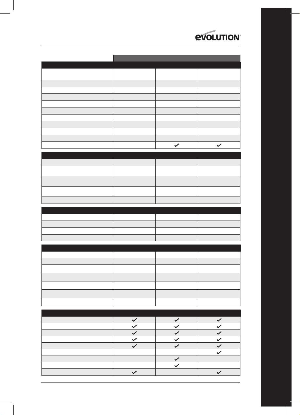
125
www.evolutionpowertools.com
IT
USA
SPECIFICHE UTENSILE R185CCS R185CCSX R185CCSX+
Modello N:
027-0004 027-0004C 027-0004A
Motore EU (220-240V ~ 50 Hz)
Motore Regno Unito (110 V ~ 50 Hz)
Motore Stati Uniti (120 V ~ 60 Hz) 15A 15A 15A
Velocità a vuoto (220-240 V)
Velocità a vuoto (110 V e 120 V) 3700 min
-1
/ rpm 3700 min
-1
/ rpm 3700 min
-1
/ rpm
Peso 10.8 lb 11.2 lb 11.2 lb
Massimo angolo di smusso della lama (in gradi)
60˚ 45˚ 45˚
Lunghezza cavo di alimentazione 13 ft 13 ft 13 ft
Tipo di base sega circolare Alluminio pressofuso Alluminio pressofuso Alluminio pressofuso
Compatibile con binario di guida taglio
CAPACITÀ DI TAGLIO R185CCS R185CCSX R185CCSX+
Piastra in acciaio dolce (Spessore massimo)
1/4” 1/4” 1/4”
Sezione quadrata in acciaio dolce
(Parete massima)
1/4” 1/4” 1/4”
Massimo spessore di taglio (0°) 2-1/2”
2-1/2” (2-5/16” con
binario guida)
2-1/2” (2-5/16” con
binario guida)
Massimo spessore di taglio (45°) 1-9/16”
1-13/16” (1-5/8” con
binario guida)
1-13/16” (1-5/8” con
binario guida)
Massimo spessore di taglio (60°) 1”
SPECIFICHE LAMA R185CCS R185CCSX R185CCSX+
Diametro lama Ø 7-1/4” Ø 7-1/4” Ø 7-1/4”
Numero denti 20 16 20
Diametro foro 25/32” 25/32” 25/32”
Intaglio 1.7mm 1.7mm 1.7mm
DATI RUMOROSITÀ E VIBRAZIONI R185CCS R185CCSX R185CCSX+
Livello pressione acustica L
pa
97,3dB(A) K=3 dB(A) 97,3dB(A) K=3 dB(A) 97,3dB(A) K=3 dB(A)
Livello potenza acustica L
wa
105,3dB(A) K=3 dB(A) 105,3dB(A) K=3 dB(A) 105,3dB(A) K=3 dB(A)
Vibrazioni - Impugnatura principale (taglio su legno)
A
h,w
= 3,347m/s
2
a
h,w
= 3,347m/s
2
a
h,w
= 3,347m/s
2
Vibrazioni - Impugnatura secondaria (taglio su legno)
A
h,w
= 3,119m/s
2
a
h,w
= 3,119m/s
2
a
h,w
= 3,119m/s
2
Vibrazioni - Impugnatura principale (taglio su metallo)
a
h,M
= 3,572m/s
2
a
h,M
= 3,572m/s
2
a
h,M
= 3,572m/s
2
Vibrazioni - Impugnatura secondaria (taglio su metallo)
a
h,M
= 3,241m/s
2
a
h,M
= 3,241m/s
2
a
h,M
= 3,241m/s
2
Incertezza K
1,5m/s
2
1,5m/s
2
1,5m/s
2
ICOMPONENTI IN DOTAZIONE R185CCS R185CCSX R185CCSX+
Lama TCT multi-materiale
Chiave esagonale (cambio lama)
Guida di arresto parallelo
Adattatore attacco polvere
Innesto portagomma polvere
Custodia da trasporto
Binario guida taglio - 340mm (13-3/8”) x3
Barra connettore e viti (x4)
Luce LED
SPECIFICHE

126
www.evolutionpowertools.com
UK / EU / AUS
R165CCSL R185CCS R185CCSX R185CCSX+
026-0001 / 026-0002 /
026-0003
027-0001C /
027-0002C / 027-0003C
027-0001 /
027-0002 / 027-0003
027-0001A /
027-0002A / 027-0003A
1200W 1600W 1600W 1600W
1200W 1600W 1600W 1600W
3700 min
-1
/ rpm 3900 min
-1
/ rpm 3900 min
-1
/ rpm 3900 min
-1
/ rpm
3700 min
-1
/ rpm 3700 min
-1
/ rpm 3700 min
-1
/ rpm 3700 min
-1
/ rpm
4.3 kg 4.9 kg 5.1 kg 5.1 kg
45˚ 60˚ 45˚ 45˚
3m 3m 3m 4m
Acciaio stampato Alluminio pressofuso Alluminio pressofuso Alluminio pressofuso
R165CCSL R185CCS R185CCSX R185CCSX+
3mm 6mm 3mm 6mm
3mm 6mm 3mm 6mm
53mm 64mm
64 mm (59 mm con binario guida) 64 mm (59 mm con binario guida)
34mm 40mm
47 mm (42 mm con binario guida) 47 mm (42 mm con binario guida)
24mm
R165CCSL R185CCS R185CCSX R185CCSX+
Ø 165mm Ø 185mm Ø 185mm Ø 185mm
14 20 16 20
20mm 20mm 20mm 20mm
1.7mm 1.7mm 1.7mm 1.7mm
R165CCSL R185CCS R185CCSX R185CCSX+
92,4dB(A) K:3dB(A) 97,3dB(A) K=3 dB(A) 97,3dB(A) K=3 dB(A) 97,3dB(A) K=3 dB(A)
103,4dB(A) K:3dB(A) 105,3dB(A) K=3 dB(A) 105,3dB(A) K=3 dB(A) 105,3dB(A) K=3 dB(A)
a
h,w
= 2,747m/s
2
a
h,w
= 3,347m/s
2
a
h,w
= 3,347m/s
2
a
h,w
= 3,347m/s
2
a
h,w
= 2,619m/s
2
a
h,w
= 3,119m/s
2
a
h,w
= 3,119m/s
2
a
h,w
= 3,119m/s
2
a
h,M
= 2,302m/s
2
a
h,M
= 3,572m/s
2
a
h,M
= 3,572m/s
2
a
h,M
= 3,572m/s
2
a
h,M
= 2,239m/s
2
a
h,M
= 3,241m/s
2
a
h,M
= 3,241m/s
2
a
h,M
= 3,241m/s
2
1,5m/s
2
1,5m/s
2
1,5m/s
2
1,5m/s
2
R165CCSL R185CCS R185CCSX R185CCSX+
127
www.evolutionpowertools.com
IT
VIBRAZIONI
(1.5) Avvertenza: La misurazione delle
vibrazioni è stata eseguita in condizioni
standard ai sensi delle normative:: EN 62841-1:
2015, EN 62841-2-5: 2014
Attenzione: Indossare protezioni acustiche!
La misurazione del valore totale dichiarato
delle vibrazioni è stata eseguita in accordo
con un metodo di verifica standard. Esso può
essere usato per confrontare un utensile con
un altro.
Il valore totale dichiarato delle vibrazioni
può essere usato inoltre per una valutazione
preliminare dell’esposizione a esse.
(1.6) ATTENZIONE: Durante l’utilizzo del
presente utensile, l’operatore può essere
esposto a un alto livello di vibrazioni trasmesse
al braccio e alla mano. L’operatore potrebbe
sviluppare la sindrome del dito bianco da
vibrazione (Sindrome di Raynaud). Tale
patologia può ridurre la sensibilità e provocare
ipotermia della mano, così come produrre un
intorpidimento generale. Coloro che utilizzano
su base regolare e in maniera prolungata nel
tempo il presente utensile devono monitorare
attentamente la condizione delle proprie
mani e dita. Qualora si manifestassero con
evidenza uno o più sintomi, consultare
immediatamente
un medico.
• La misurazione e la valutazione
dell’esposizione alle vibrazioni trasmesse
all’arto sul posto di lavoro è contemplata
nelle normative: EN 62841-1 and EN 62841-
2-5
• Numerosi fattori possono influenzare
il livello reale delle vibrazioni durante
il funzionamento, come ad esempio la
condizione e l’orientamento della superficie
di lavoro e il tipo e lo stato dell’apparecchio
in uso. Tali fattori devono essere valutati
prima di ogni utilizzo, e, laddove possibile,
devono essere messe in atto le idonee
pratiche lavorative. La buona gestione dei
seguenti fattori può concorrere a ridurre gli
effetti delle vibrazioni:
Gestione dell’utensile
• Maneggiare l’utensile con cura,
consentendogli di effettuare il proprio
lavoro.
• Evitare di usare eccessiva forza fisica sui
controlli dell’utensile.
• Considerare la propria sicurezza ed
equilibrio, e l’orientamento dell’utensile
durante l’uso.
Superficie di lavoro
• Esaminare il materiale della superficie
di lavoro; la sua condizione, densità,
resistenza, rigidità e orientamento.
ATTENZIONE: L’emissione di vibrazioni
durante l’uso effettivo dell’utensile può
differenziarsi dal valore totale dichiarato in
base al modo in cui l’utensile è impiegato.
La necessità di identificare misure di sicurezza
che tutelino l’operatore sono basate su
una stima dell’esposizione al pericolo
nelle condizioni d’uso reali (prendendo in
considerazione tutti i componenti
del ciclo di funzionamento, così come le
tempistiche di spegnimento dell’utensile, del
suo funzionamento a vuoto,
in aggiunta al tempo di attivazione).
(1.7 ) ETICHETTE E SIMBOLI
ATTENZIONE: Non mettere in funzione il
presente apparecchio qualora le etichette di
sicurezza e/o le istruzioni risultino mancanti o
danneggiate. Contattare Evolution
Power Tools per le etichette sostitutive.
Avvertenza: Tutti o alcuni dei seguenti
simboli possono essere presenti nel manuale
o sul prodotto.
(1.8)
Simbolo Descrizione
V
Volt
A
Ampere
Hz
Hertz
Min
-1
/ RPM
Velocità
~
Corrente alternata
n
o
Velocità a vuoto
Indossare occhiali protettivi
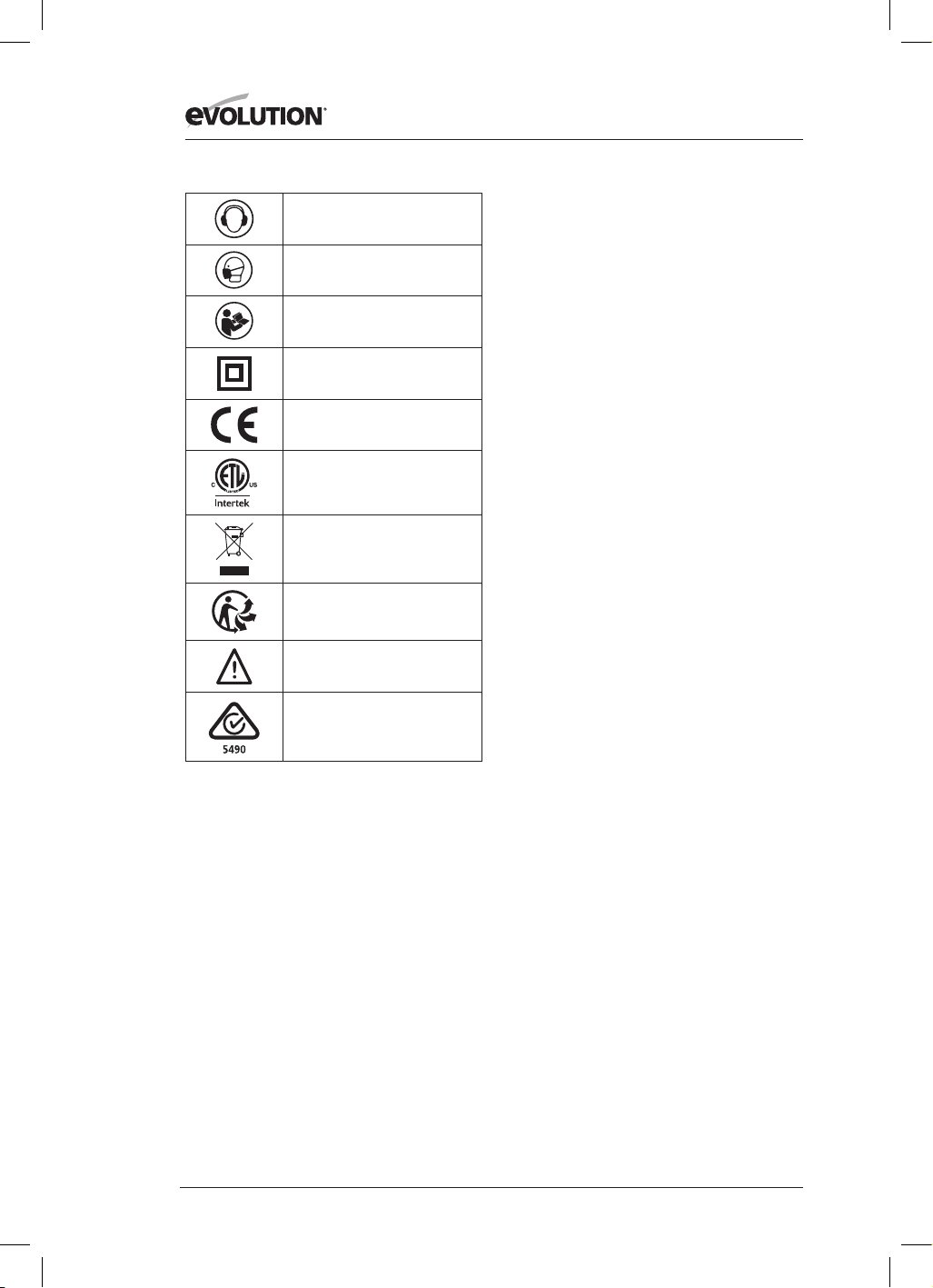
128
www.evolutionpowertools.com
Indossare protezioni auricolari
Indossare protezioni antipolvere
Leggere le istruzioni
Doppio isolamento
Certificazione CE
Certificazione ETL
Smaltimento di apparecchiature
elettriche ed elettroniche
Smaltimento e riciclaggio rifiuti
secondo la normativa Triman
Attenzione
Marchio di conformità ai requisiti
per le apparecchiature elettriche ed elettroniche
(RCM). Standard Australia/Nuova Zelanda
(1.9) DESTINAZIONE D’USO
DEL PRESENTE UTENSILE
ELETTRICO
ATTENZIONE: Il presente prodotto è una sega
circolare a funzionamento manuale ed è stata
progettata per essere utilizzata con specifiche
lame Evolution. Utilizzare esclusivamente
accessori progettati per l’utilizzo sul presente
apparecchio e/o quelli espressamente
raccomandati da Evolution Power Tools Ltd.
Se equipaggiato con una lama idonea
il presente utensile può essere utilizzato per
tagliare:
Acciaio dolce, alluminio, legno
Avvertenza: Effettuare tagli sull’acciaio
zincato riduce la durata della lama.
(1.10) USO NON CONSENTITO
DEL PRESENTE UTENSILE
ELETTRICO
ATTENZIONE: TIl presente prodotto è una
sega circolare a funzionamento manuale e
deve essere utilizzata esclusivamente come
tale. Essa non deve in alcun modo essere
modificata, o utilizzata per alimentare altro
apparecchio o manovrare un qualunque
accessorio differente da quelli identificati nel
presente manuale di istruzioni.
(1.11) ATTENZIONE: Il presente utensile
non è progettato per essere impiegato da
persone (bambini inclusi) con capacità fisiche,
sensoriali o mentali ridotte, o da utenti privi
di esperienza e conoscenza, a meno che
essi non siano supervisionati o istruiti da un
responsabile competente in tal senso sul suo
utilizzo in sicurezza.
È necessario sorvegliare i bambini per
assicurarsi che essi non abbiano accesso al
presente utensile, e che non sia consentito
loro di giocarci.
(1.12) SICUREZZA ELETTRICA
Il presente utensile è dotato di un modello di
presa elettrica e di un cavo di alimentazione
idonei al mercato di destinazione. Qualora il
cavo di alimentazione sia danneggiato, esso
deve essere sostituito da un cavo specifico
o da uno assemblato appositamente dal
produttore o dal suo servizio di assistenza.
(1.13) USO ESTERNO
ATTENZIONE:
ATTENZIONE: Per la propria sicurezza,
qualora il presente apparecchio sia utilizzato
all’aperto, non deve essere esposto alla
pioggia o impiegato in ambienti umidi. Non
posizionare l’utensile su superfici umide.
Utilizzare un banco da lavoro asciutto e
pulito se disponibile. Per una protezione
supplementare, utilizzare un interruttore
differenziale (R.C.D.) che interrompa
l’alimentazione qualora la dispersione di
corrente a terra superi i 30mA per 30ms.
Verificare sempre il funzionamento
dell’interruttore differenziale (R.C.D.) prima di
utilizzare l’utensile.
Qualora sia necessario un cavo di prolunga,
deve essere di tipo idoneo all’utilizzo esterno
e contrassegnato di conseguenza. Quando si
utilizza un cavo di prolunga, devono essere

129
www.evolutionpowertools.com
IT
rispettate le istruzioni del produttore.
(2.1) ISTRUZIONI GENERALI SULLA
SICUREZZA
(Le presenti istruzioni generali di sicurezza
degli utensili elettrici sono redatte in accordo
alla normativa EN 62841-1: 2015).
ATTENZIONE: Leggere per intero le istruzioni
e le avvertenze di sicurezza.
Il mancato rispetto delle avvertenze e
delle istruzioni può comportare scosse
elettriche, rischio di incendio e/o gravi lesioni.
Conservare tutte le avvertenze e le istruzioni
per future consultazioni.
La dicitura “utensile elettrico” nelle avvertenze
si riferisce al presente utensile elettrico
alimentato a muro (con cavo) o a batterie
(senza cavo).
(2.2) 1) Avvertenze generali sulla sicurezza
degli utensili elettrici [Sicurezza dell’area
di lavoro]
a) ) Tenere l’area di lavoro pulita e ben
illuminata. Le aree disordinate e poco
illuminate favoriscono gli incidenti.
b) Non azionare l’utensile elettrico in
un’atmosfera potenzialmente esplosiva,
come in presenza di liquidi, gas o polveri
infiammabili. Gli utensili elettrici
generano scintille che possono innescare
polveri o vapori.
c) Tenere bambini e presenti a distanza
mentre l’apparecchio è in funzione. Le
distrazioni possono causare perdita di
controllo.
(2.3) 2) Avvertenze generali sulla sicurezza
degli utensili elettrici [Sicurezza elettrica]
a) Le spine di alimentazione degli utensili
elettrici devono essere adeguate alla presa
a muro. In nessuna circostanza e in alcun
modo modificare la spina elettrica.
Non utilizzare adattatori di attacco elettrico
in combinazione con utensili elettrici
dotati di messa a terra. Spine elettriche non
modificate e prese adeguate riducono il rischio
di folgorazione.
b) Evitare il contatto del corpo con superfici
dotate di messa a terra, come tubature,
caloriferi, fornelli e frigoriferi. Si registra un
aumento del rischio di scossa elettrica quando
il corpo risulta in contatto con una messa a
terra.
c) Non esporre utensili elettrici alla pioggia
o al rischio di bagnarsi. L’ingresso di acqua
in un utensile elettrico aumenta il rischio di
folgorazione.
d) Non sottoporre a eccessivo lavoro il cavo
di alimentazione. Non utilizzare mai il cavo
per trasportare, tirare o scollegare l’utensile
elettrico. Tenere il cavo al riparo da calore,
olio, spigoli vivi o parti in movimento.
I cavi danneggiati o aggrovigliati aumentano il
rischio di folgorazione.
e) Quando si utilizza un utensile elettrico
in ambiente esterno, impiegare un cavo
di prolunga idoneo all’uso all’aperto.
Impiegare un cavo idoneo all’utilizzo all’aperto
riduce il rischio di folgorazione.
f) Qualora sia indispensabile utilizzare
l’utensile elettrico in ambiente umido,
impiegare un alimentatore protetto dotato
di interruttore differenziale (RCD).
L’utilizzo di un RCD riduce il rischio
di folgorazione.
Avvertenza: Il prodotto è idoneo all’utilizzo
soltanto in locali che abbiano una potenza
della corrente di servizio ≥100A per fase,
erogata da una rete di distribuzione con
una potenza nominale di voltaggio a 230 V.
Qualora necessario, contattare la compagnia
elettrica per accertarsi che l’alimentazione
elettrica in uscita dalla rete di distribuzione
pubblica sia adeguata per collegare il
prodotto.
(2.4) 3) Avvertenze generali sulla sicurezza
degli utensili elettrici [Sicurezza
personale].
a) Lavorare con prudenza, controllare quel
che si sta facendo e utilizzare il buon senso
quando si adopera un utensile elettrico.
Non utilizzare un utensile elettrico quando si è
stanchi o sotto l’effetto di stupefacenti, alcool
o farmaci. Un attimo di distrazione durante
l’utilizzo di utensili elettrici può risultare in una
grave lesione personale.
b) Utilizzare l’equipaggiamento di
protezione personale. Indossare sempre
protezioni per gli occhi. L’utilizzo di
equipaggiamento di protezione come
maschera antipolvere, calzature anti
infortunistiche antisdrucciolo, caschetto e
protezioni auricolari nelle situazioni idonee
riduce il rischio di lesioni personali.
c) Prevenire attivazioni indesiderate.
Quando si solleva o trasporta l’apparecchio,
assicurarsi che l’interruttore sia nella posizione
di spegnimento prima di collegarlo a una fonte

130
www.evolutionpowertools.com
di alimentazione e/o a un pacco batterie.
Non trasportare un utensile elettrico con le dita
sull’interruttore o dargli corrente quando tale
comando è sulla posizione di accensione
facilita il verificarsi di incidenti.
d) Rimuovere qualunque chiave o brugola
di regolazione dal bullone della lama prima
di avviare l’utensile elettrico. Una chiave
o una brugola rimasta attaccata a una parte
rotante di un utensile elettrico può causare
lesioni personali.
e) Non sporgersi troppo. Mantenere sempre i
piedi saldi a terra e un buon equilibrio.
Ciò garantisce un controllo migliore dell’utensile
elettrico in situazioni impreviste.
f) Indossare l’abbigliamento adeguato. Non
indossare indumenti larghi o gioielli. Tenere i
propri capelli, indumenti e guanti lontani dalle
parti in movimento. Indumenti larghi, gioielli
e capelli lunghi possono rimanere intrappolati
nelle parti in movimento.
g) Qualora gli apparecchi siano provvisti di
collegamento a dispositivi di aspirazione
e raccolta polveri, accertarsi che essi siano
collegati e utilizzati adeguatamente.
L’utilizzo di un dispositivo per la raccolta di
polveri può ridurre i rischi legati alla presenza
delle stesse.
h) Non permettere che la familiarità d’uso
agli utensili dovuta al loro frequente
utilizzo produca indifferenza e noncuranza
dei principi di sicurezza. Un’azione
sconsiderata può produrre conseguenze gravi
nel giro di pochi secondi.
(2.5) 4) Avvertenze generali sulla sicurezza
degli utensili elettrici [Utilizzo e
manutenzione dell’utensile elettrico].
a) Non forzare l’utensile elettrico. Utilizzare
l’utensile elettrico corretto per la propria
applicazione. L’utensile elettrico corretto
eseguirà il lavoro in maniera più efficiente e
sicura alla velocità per la quale esso è stato
progettato.
b) Non utilizzare l’utensile elettrico se
l’interruttore non si accende o non si
spegne. Qualunque utensile elettrico
che non possa essere controllato tramite
l’interruttore è pericoloso e deve essere
riparato.
c) Scollegare l’utensile elettrico dalla
fonte di alimentazione prima di eseguire
qualunque riparazione, cambio di accessori,
o di riporlo. Tali misure preventive di sicurezza
riducono il rischio di avviamento accidentale
dell’utensile elettrico.
d) Riporre gli utensili elettrici inattivi e
tenerli lontani dalla portata dei bambini.
Non consentire a persone che non abbiano
familiarità con il loro funzionamento o con
le presenti istruzioni di metterli in funzione.
Gli utensili elettrici sono pericolosi nelle mani
di utenti inesperti.
e) Manutenzione degli utensili elettrici.
Verificare l’eventuale disallineamento o
l’inceppamento delle parti in movimento,
il loro danneggiamento o qualunque
altra condizione che possa influire sul
funzionamento dell’apparecchio. Qualora
danneggiato, prima dell’utilizzo far riparare
l’utensile elettrico. Numerosi incidenti sono
causati da utensili elettrici soggetti a una
manutenzione inadeguata.
f) Mantenere gli strumenti da taglio affilati
e puliti. Gli strumenti da taglio su cui è stata
effettuata un’adeguata manutenzione e con
lame affilate presentano una probabilità
inferiore di incepparsi e sono più facili da
controllare.
g) Utilizzare l’utensile elettrico, gli accessori
e le punte di taglio in accordo alle presenti
istruzioni, prendendo in considerazione le
condizioni di lavorazione e il compito da
eseguire. L’utilizzo di un utensile elettrico per
un compito differente da quello per il quale è
stato concepito può comportare rischi.
h) Tenere le impugnature e le superfici di
presa asciutte, pulite e libere da lubrificanti
e grassi. Impugnature e superfici di presa
scivolose non consentono la gestione
in sicurezza e il controllo dell’utensile in
situazioni impreviste.
(2.6) 5) Avvertenze generali sulla sicurezza
degli utensili elettrici [Assistenza]
a) Accertarsi di far riparare il proprio
utensile elettrico solo da personale
qualificato che impieghi ricambi originali
e identici. Ciò consentirà di preservare la
sicurezza dell’utensile elettrico.
(2.7) INDICAZIONI SANITARIE
ATTENZIONE: Durante l’utilizzo del presente
apparecchio, si possono produrre particelle
di polvere. In alcune circostanze, in relazione
ai materiali con i quali si sta lavorando, tali
polveri possono risultare particolarmente
dannose. Qualora si abbia il sospetto che
la vernice sulle superfici del materiale
contenga piombo, richiedere una consulenza

131
www.evolutionpowertools.com
IT
professionale. Le vernici a base di piombo
devono essere rimosse esclusivamente
da professionisti. Si sconsiglia fortemente
di provare a farlo per conto proprio.
Una volta che la polvere si è depositata sulle
superfici, il contatto tra mani e bocca può
causare l’ingestione di piombo. L’esposizione
a livelli anche minimi di piombo può
causare danni neurologici e al sistema
nervoso irreversibili. Bambini e feti sono
particolarmente sensibili a tale pericolo.
Si consiglia di valutare i rischi associati ai
materiali con i quali si lavora e di ridurre i rischi
di esposizione.
Data la potenziale pericolosità delle polveri
prodotte da alcuni materiali, raccomandiamo,
durante l’utilizzo del presente utensile, di
usare una mascherina certificata per naso e
bocca con filtri sostituibili.
È necessario sempre:
• Lavorare in un’area ben ventilata.
• Lavorare con materiale di sicurezza
approvato, come maschere antipolvere
specificamente progettate per filtrare
particelle microscopiche.
(2.8) ATTENZIONE: il funzionamento di
qualunque utensile elettrico può comportare
l’eventualità che un oggetto estraneo sia
scagliato verso gli occhi, causando lesioni
oculari gravi. Prima di iniziare a utilizzare un
utensile elettrico, indossare sempre occhiali
di protezione o occhiali di sicurezza con
protezioni laterali o una maschera facciale
completa quando necessario.
ISTRUZIONI DI SICUREZZA PER TUTTI I TIPI
DI SEGA [Procedure di taglio]
a) PERICOLO: Tenere le mani distanti
dall’area di taglio della lama. Tenere
la seconda mano sull’impugnatura
secondaria o sul vano motore. Se entrambe
le mani impugnano la sega, non potranno
essere soggette a tagli.
b) Non mettere le mani sotto il pezzo in
lavorazione. La protezione coprilama non
può proteggere dalla lama sotto il pezzo in
lavorazione.
c) Regolare la profondità di taglio allo spessore
del pezzo da lavorare. Al di sotto del pezzo da
lavorare dovrebbe essere visibile meno di un
intero dente della dentatura della lama.
d) Non tenere mai il pezzo in lavorazione tra
le proprie mani o sopra le gambe durante
l’operazione di taglio. Assicurare il pezzo da
lavorare a una piattaforma stabile.
È importante sostenere adeguatamente il
pezzo per ridurre al massimo l’esposizione del
corpo, la forzatura della lama e la perdita di
controllo.
e) Quando si effettuano operazioni durante
le quali l’utensile potrebbe entrare in
contatto con fili elettrici nascosti o con il
proprio cavo, impugnare l’utensile dalle
superfici di presa isolate. Il contatto con un
filo elettrico attivo renderà conduttive anche
le parti metalliche esposte dell’utensile e
potrebbe provocare una scossa elettrica per
l’operatore.
f) Quando si esegue un taglio longitudinale,
usare sempre una guida ad arresto parallelo
o una guida a profilo lineare. Ciò migliora
l’accuratezza del taglio e riduce l’eventualità
che la lama sforzi eccessivamente.
g) Utilizzare sempre lame con la corretta
dimensione e forma (diamantata contro
arrotondata) dei fori del mandrino. Le
lame che non combaciano con la struttura
di innesto della sega non saranno centrate,
provocando perdita di controllo durante il
taglio.
h) Non utilizzare mai rondelle o bulloni
errati o danneggiati per la lama. Le rondelle
e i bulloni della lama sono stati appositamente
realizzati per la sega, per garantire il massimo
delle prestazioni e della sicurezza durante il
funzionamento.
(3.2) [Cause del rinculo e relative
avvertenze]
Il rinculo rappresenta una reazione
improvvisa a una lama schiacciata, inceppata
o disallineata, che causa l’inalberamento
senza controllo della sega, e la sua espulsione
dal pezzo in lavorazione in direzione
dell’operatore;
Quando la lama è fortemente schiacciata o
inceppata sull’innesto di taglio, essa si blocca
e la reazione del motore causa la spinta
repentina dell’unità verso l’operatore;
Se la lama si piega o perde l’allineamento
durante il taglio, i denti sul suo lato posteriore
possono incastrarsi sul lato superiore del
legno, con il risultato che la lama si estrarrà
dall’intaglio e sarà sbalzata verso l’operatore.
(3.3)
Il fenomeno del rinculo è il risultato di un

132
www.evolutionpowertools.com
utilizzo scorretto della sega e/o di procedure
e condizioni di lavorazione errati e può essere
evitato adottando le idonee precauzioni sotto
descritte.
a) Mantenere una presa salda con entrambe
le mani sulla sega e posizionare le proprie
braccia in maniera da resistere alla spinta di
un eventuale rinculo.
Posizionare il proprio corpo su uno dei due
lati della lama, ma non in linea con essa.
Il rinculo può causare che la sega sia sbalzata
all’indietro, ma l’impatto di tale fenomeno
può essere controllato dall’operatore se sono
adottate idonee precauzioni.
b) Quando una lama si blocca, o se
è necessario per qualunque ragione
interrompere un taglio, rilasciare
l’interruttore a pressione e mantenere la
sega spenta nel taglio del materiale fin
quando la lama non si sia del tutto fermata.
Non cercare mai di rimuovere la sega dal
materiale o di spingerla indietro mentre la
lama è in movimento, altrimenti potrebbe
verificarsi un rinculo. Ispezionare e prendere
le adeguate contromisure per evitare le
possibili cause di inceppamento della lama.
c) Quando si riavvia la sega nel pezzo in
lavorazione, centrare la lama nel solco del
taglio in maniera tale che i suoi denti non siano
incastrati nel materiale. Quando una lama si
inceppa, può essere sbalzata fuori o respinta dal
pezzo in lavorazione nel momento in cui la sega
è riavviata.
d) Non utilizzare lame smussate o
danneggiate. ULame non affilate o regolate
inadeguatamente producono solchi di
taglio stretti che causano eccessiva frizione,
inceppamento della lama e rinculo.
e) Prima di avviare un taglio, le leve di
bloccaggio della profondità della lama e
della regolazione dello smusso devono
essere strette e bloccate. Lo spostamento della
regolazione della lama durante il taglio può
causare inceppamento e rinculo.
f) Prima di avviare il taglio, le leve di
bloccaggio della profondità della lama e
della regolazione dello smusso devono
essere strette e bloccate. Lo spostamento
della regolazione della lama durante il taglio
può causare inceppamento e rinculo.
g) Usare estrema attenzione quando si
effettuano tagli in pareti esistenti o altre
aree cieche. La lama sporgente può tagliare
oggetti con il rischio che si verifiche un effetto
di rinculo.
FUNZIONE DI PROTEZIONE
COPRILAMA INFERIORE
a) Verificare la corretta chiusura del
coprilama inferiore prima di ogni utilizzo.
Non adoperare la sega qualora il coprilama
inferiore non si muova fluidamente e si
chiuda istantaneamente.
Non bloccare o legare mai il coprilama
inferiore in posizione aperta. Qualora la sega
cada accidentalmente, il coprilama inferiore
potrebbe piegarsi. Sollevare il coprilama
inferiore con l’impugnatura retrattile e
assicurarsi che si muova liberamente e che non
tocchi la lama o altre parti, in tutti gli angoli e
le profondità di taglio.
b) Verificare il funzionamento della
molla del coprilama inferiore. Qualora
il coprilama e la molla non funzionino
a dovere, devono essere riparati prima
dell’uso. Il coprilama inferiore può funzionare
lentamente a causa di parti danneggiate,
concrezioni appiccicose e accumulo di detriti.
c) Il coprilama inferiore può essere retratto
manualmente solo per tagli speciali quali il
taglio dal pieno e i tagli compositi.
Sollevare il coprilama inferiore
dall’impugnatura retrattile e appena la
lama entra nel materiale, il coprilama deve
essere rilasciato. Per tutti gli altri tipi di taglio,
il coprilama inferiore deve funzionare in modo
automatico.
d) Verificare sempre a vista che il coprilama
inferiore copra la lama prima di appoggiare
la sega su un banco da lavoro o per terra.
Una lama non protetta e in rotazione causerà
l’arretramento della sega, con il risultato di
tagliare qualunque cosa essa trovi sul suo
percorso. Prendere confidenza con il tempo
necessario alla lama per fermarsi dopo il
rilascio dell’interruttore.
ISTRUZIONI SUPPLEMENTARI
SULLA SICUREZZA
PER LE SEGHE CIRCOLARI
a) Non utilizzare lame in acciaio ad alta
velocità (HSS) per la sega.
b) Ispezionare l’utensile e la lama
prima di ogni utilizzo. Non impiegare lame
deformate, fessurate, usurate o comunque
danneggiate.
c) Non utilizzare in alcuna circostanza la
sega senza il sistema di protezione della
lama originale. Non bloccare la protezione
coprilama mobile nella posizione

133
www.evolutionpowertools.com
IT
aperta. Accertarsi che il coprilama funzioni in
maniera fluida senza inceppamenti.
d) Utilizzare esclusivamente lame che
rispettino le caratteristiche specificate
nel manuale. Prima di utilizzare accessori,
confrontare sempre il loro numero massimo di
RPM consentiti con quello dell’apparecchio.
e) Non utilizzare mole abrasive.
f) Utilizzare esclusivamente diametri di
lama in accordo con le indicazioni.
(3.4) ATTENZIONE: In caso vi siano delle parti
mancanti, non mettere in funzione il proprio
apparecchio fin quando esse non siano state
sostituite. Il mancato rispetto della presente
regola può comportare gravi lesioni.
(4.1) INFORMAZIONI INTRODUTTIVE
- DISIMBALLAGGIO
Attenzione: Il pacco contiene oggetti taglienti.
Prestare attenzione durante l’apertura.
Rimuovere l’apparecchio insieme agli accessori
inclusi nell’imballo. Controllare attentamente le
buone condizioni dell’apparecchio e verificare
che siano presenti tutti gli accessori elencati nel
presente manuale. Accertarsi inoltre che tutti gli
accessori siano completi in ogni loro parte.
Qualora si riscontrino parti mancanti,
l’apparecchio e i suoi accessori devono essere
restituiti al rivenditore insieme all’imballo
originale.
Non gettare via l’imballo. Conservarlo intatto
per la durata del periodo di garanzia. Smaltire
il materiale d’imballaggio in maniera eco-
responsabile. Riciclare laddove possibile.
Non consentire ai bambini di giocare con le
buste di plastica vuote a causa del rischio di
soffocamento.
(4.3) MANUALI DI ISTRUZIONI
EVOLUTION
Evolution Power Tools munisce ogni prodotto
di un manuale di istruzioni.
Ogni manuale specifico è concepito e
progettato per fornire informazioni utili e
facilmente accessibili circa l’utilizzo sicuro, la
cura e la manutenzione del prodotto.
Fare riferimento alla informazioni contenute
nel manuale consentirà all’operatore di
sfruttare a pieno e in sicurezza il potenziale
dell’utensile. La politica di continuo
miglioramento dei prodotti di Evolution può
significare che, in maniera molto occasionale,
i contenuti del manuale non rispecchino
completamente gli ultimi miglioramenti o
aggiornamenti apportati su uno specifico
prodotto.
Gli aggiornamenti/miglioramenti apportati
su uno specifico prodotto possono verificarsi
in conseguenza ad avanzamenti tecnologici
o cambi di quadro legislativo di un paese di
importazione del prodotto, ecc.
Se si è in qualche modo incerti su un
qualunque aspetto dell’utilizzo, cura o
manutenzione di un prodotto Evolution,
contattare l’assistenza telefonica dedicata,
la quale sarà in grado di fornire informazioni
aggiornate e consigli supplementari.
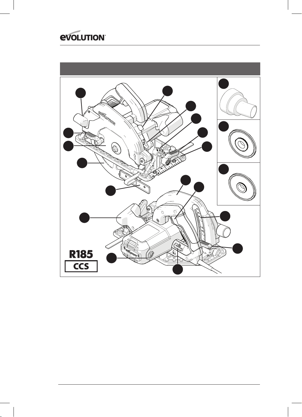
134
www.evolutionpowertools.com
USA
1. PORTA DI ESPULSIONE DEL MATERIALE
TAGLIATO
2. LEVA A CHIUSURA
3. LAMA TCT MULTI-MATERIALE
4. COPRILAMA INFERIORE
5. GUIDA DI ARRESTO PARALLELO
6. IMPUGNATURA ANTERIORE ERGONOMICA
7. SPAZZOLE DI CARBONE
8. CHIAVE ESAGONALE 5/16” (CAMBIO LAMA)
9. LEVA DI BLOCCAGGIO DELLA
REGOLAZIONE DI PROFONDITÀ
10. SCALA DI PROFONDITÀ
11. INTERRUTTORE ON / OFF IMPUGNATURA
POSTERIORE
12. COPRILAMA SUPERIORE
13. PIASTRA UNICA DI PRECISIONE
14. LEVA A CHIUSURA REGOLAZIONE SMUSSO
15. SCALA GONIOMETRICA
16. PULSANTE DI BLOCCO MANDRINO
17. LUCE LED
18. ADATTATORE ATTACCO POLVERE
19. FLANGIA INTERNA LAMA 25/32”
20. FLANGIA INTERNA LAMA 15,8MM
13
15
17
18
19
20
4
14
5
1
3
8
9
10
11
6
7
2
16
12
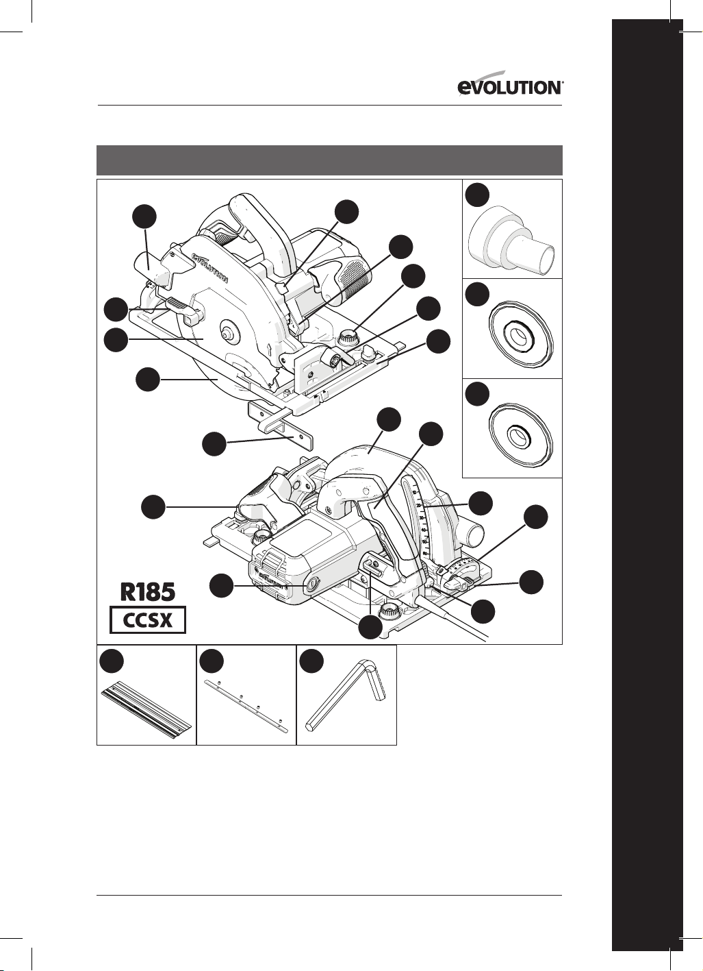
135
www.evolutionpowertools.com
IT
USA
1. PORTA DI ESPULSIONE DEL
MATERIALE TAGLIATO
2. LEVA A CHIUSURA
3. LAMA TCT MULTI-MATERIALE
4. COPRILAMA INFERIORE
5. GUIDA DI ARRESTO PARALLELO
6. IMPUGNATURA ANTERIORE
ERGONOMICA
7. SPAZZOLE DI CARBONE
8. CHIAVE ESAGONALE 5/16” (CAMBIO
LAMA)
9. LEVA REGOLAZIONE DI PROFONDITÀ
10. SCALA DI PROFONDITÀ
11. INTERRUTTORE ON / OFF
IMPUGNATURA POSTERIORE
12. COPRILAMA SUPERIORE
13. PIASTRA UNICA DI PRECISIONE
COMPATIBILE CON BINARIO GUIDA
14. LEVA A CHIUSURA
15. SCALA GONIOMETRICA POSTERIORE
16. PULSANTE DI BLOCCO MANDRINO
17. LUCE LED
18. ADATTATORE ATTACCO POLVERE
19. FLANGIA INTERNA LAMA 25/32”
20. FLANGIA INTERNA LAMA 15,8MM
21. PULSANTI REGOLAZIONE BINARIO
GUIDA
22. VITE AD ALETTE SMUSSO POSTERIORE
23. 3x BINARIO GUIDA DA 13-3/8”
24. 4x BARRE COLLEGAMENTO BINARIO
GUIDA
25. CHIAVE ESAGONALE (BINARIO
GUIDA) 1/8”
13
21
15
17
18
19
20
4
14
5
1
3
8
9
10
22
11
6
7
2
16
12
23 24
25
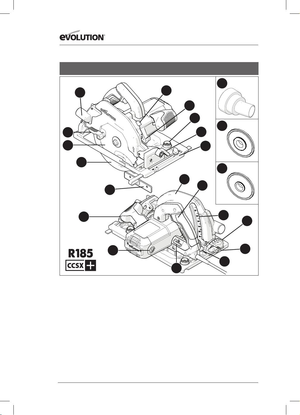
136
www.evolutionpowertools.com
USA
1. PORTA DI ESPULSIONE DEL MATERIALE TAGLIATO
2. LEVA A CHIUSURA
3. LAMA TCT MULTI-MATERIALE
4. COPRILAMA INFERIORE
5. GUIDA DI ARRESTO PARALLELO
6. IMPUGNATURA ANTERIORE ERGONOMICA
7. SPAZZOLE DI CARBONE
8. CHIAVE ESAGONALE 8MM (CAMBIO LAMA)
9. LEVA DI BLOCCAGGIO DELLA REGOLAZIONE DI
PROFONDITÀ
10. SCALA DI PROFONDITÀ
11. INTERRUTTORE ON / OFF IMPUGNATURA
POSTERIORE
12. COPRILAMA SUPERIORE
13. PIASTRA UNICA DI PRECISIONE COMPATIBILE
CON BINARIO GUIDA
14. LEVA A CHIUSURA
15. SCALA GONIOMETRICA POSTERIORE
16. PULSANTE DI BLOCCO MANDRINO
17. LUCE LED
18. ADATTATORE ATTACCO POLVERE
19. FLANGIA INTERNA LAMA 25/32”
20. FLANGIA INTERNA LAMA 15,8MM
21. PULSANTI REGOLAZIONE BINARIO GUIDA
22. VITE AD ALETTE SMUSSO POSTERIORE
13
21
15
17
18
19
20
4
14
5
1
3
8
9
10
22
11
6
7
2
16
12

137
www.evolutionpowertools.com
IT
13
15
4
14
5
1
3
8
9
10
11
6
7
2
16
12
1. PORTA DI ESPULSIONE DEL MATERIALE
TAGLIATO
2. LEVA A CHIUSURA
3. LAMA TCT MULTI-MATERIALE
4. COPRILAMA INFERIORE
5. GUIDA DI ARRESTO PARALLELO
6. IMPUGNATURA ANTERIORE ERGONOMICA
7. SPAZZOLE DI CARBONE
8. CHIAVE ESAGONALE 8MM (CAMBIO LAMA)
9. LEVA DI BLOCCAGGIO DELLA
REGOLAZIONE DI PROFONDITÀ
10. SCALA DI PROFONDITÀ
11. IMPUGNATURA POSTERIORE CON ANNESSO
INTERRUTTORE DI SICUREZZA ON/OFF
12. COPRILAMA SUPERIORE
13. PIASTRA UNICA DI PRECISIONE
14. LEVA A CHIUSURA
15. SCALA GONIOMETRICA
16. PULSANTE DI BLOCCO MANDRINO
UK / EU / AUS

138
www.evolutionpowertools.com
1. PORTA DI ESPULSIONE DEL MATERIALE
TAGLIATO
2. LEVA A CHIUSURA
3. LAMA TCT MULTI-MATERIALE
4. COPRILAMA INFERIORE
5. GUIDA DI ARRESTO PARALLELO
6. IMPUGNATURA ANTERIORE ERGONOMICA
7. SPAZZOLE DI CARBONE
8. CHIAVE ESAGONALE 8MM (CAMBIO LAMA)
9. LEVA DI BLOCCAGGIO DELLA
REGOLAZIONE DI PROFONDITÀ
10. SCALA DI PROFONDITÀ
11. IMPUGNATURA POSTERIORE CON ANNESSO
INTERRUTTORE DI SICUREZZA ON/OFF
12. COPRILAMA SUPERIORE
13. PIASTRA UNICA DI PRECISIONE
14. LEVA A CHIUSURA
15. SCALA GONIOMETRICA
16. PULSANTE DI BLOCCO MANDRINO
17. ADATTATORE ATTACCO POLVERE
UK / EU
13
15
17
4
14
5
1
3
8
9
10
11
6
7
2
16
12

139
www.evolutionpowertools.com
IT
13
18
15
17
20
21
22
4
14
5
1
3
8
9
10
19
11
6
7
2
16
12
1. PORTA DI ESPULSIONE DEL MATERIALE TAGLIATO
2. LEVA A CHIUSURA
3. LAMA TCT MULTI-MATERIALE
4. COPRILAMA INFERIORE
5. GUIDA DI ARRESTO PARALLELO
6. IMPUGNATURA ANTERIORE ERGONOMICA
7. SPAZZOLE DI CARBONE
8. CHIAVE ESAGONALE 8MM (CAMBIO LAMA)
9. LEVA DI BLOCCAGGIO DELLA REGOLAZIONE DI
PROFONDITÀ
10. SCALA DI PROFONDITÀ
11. IMPUGNATURA POSTERIORE CON ANNESSO
INTERRUTTORE DI SICUREZZA ON/OFF
12. COPRILAMA SUPERIORE
13. PIASTRA UNICA DI PRECISIONE COMPATIBILE
CON BINARIO GUIDA
14. LEVA A CHIUSURA
15. SCALA GONIOMETRICA POSTERIORE
16. PULSANTE DI BLOCCO MANDRINO
17. ADATTATORE ATTACCO POLVERE
18. PULSANTI REGOLAZIONE BINARIO GUIDA
19. VITE AD ALETTE SMUSSO POSTERIORE
20. 3x BINARIO GUIDA DA 340 mm
21. 4x BARRE COLLEGAMENTO BINARIO GUIDA
22. CHIAVE ESAGONALE DA 3mm
UK / EU

140
www.evolutionpowertools.com
UK / EU
1. PORTA DI ESPULSIONE DEL MATERIALE
TAGLIATO
2. LEVA A CHIUSURA
3. LAMA TCT MULTI-MATERIALE
4. COPRILAMA INFERIORE
5. GUIDA DI ARRESTO PARALLELO
6. IMPUGNATURA ANTERIORE ERGONOMICA
7. SPAZZOLE DI CARBONE
8. CHIAVE ESAGONALE 8MM (CAMBIO LAMA)
9. LEVA DI BLOCCAGGIO DELLA
REGOLAZIONE DI PROFONDITÀ
10. SCALA DI PROFONDITÀ
11. IMPUGNATURA POSTERIORE CON ANNESSO
INTERRUTTORE DI SICUREZZA ON/OFF
12. COPRILAMA SUPERIORE
13. PIASTRA UNICA DI PRECISIONE
COMPATIBILE CON BINARIO GUIDA
14. LEVA A CHIUSURA
15. SCALA GONIOMETRICA POSTERIORE
16. PULSANTE DI BLOCCO MANDRINO
17. ADATTATORE ATTACCO POLVERE
18. PULSANTI REGOLAZIONE BINARIO GUIDA
19. VITE AD ALETTE SMUSSO POSTERIORE
13
18
15
17
4
14
5
1
3
8
9
10
19
11
6
7
2
16
12

141
www.evolutionpowertools.com
IT
Fig. 3Fig. 2
Fig. 4
Fig. 1
Fig. 8
Fig. 6Fig. 5
Fig. 9
Fig. 10
Fig. 7a Fig. 7b Fig. 7c

142
www.evolutionpowertools.com
Fig. 11
Fig. 12
Fig. 13
Fig. 14
Fig. 15
Fig. 16
Fig. 17 Fig. 18
Fig. 21Fig. 20
Fig. 19
Fig. 22
1 -2mm

143
www.evolutionpowertools.com
IT
Fig. 27Fig. 26
Fig. 25
Fig. 30 Fig. 31
Fig. 34
Fig. 24Fig. 23
Adattatore attacco polvere USA
Adattatore attacco polvere UE
Fig. 28
Fig. 29
Fig. 32 Fig. 33

144
www.evolutionpowertools.com
(10) PREPARAZIONE
ATTENZIONE: Scollegare sempre l’utensile
dalla fonte di alimentazione prima di eseguire
qualunque regolazione.
Avvertenza: I presenti apparecchi sono
equipaggiati con un cavo di alimentazione e una
spina elettrica omologati per l’uso nel paese di
destinazione. Non modificare o manomettere il
cavo di alimentazione.
(10.1) INSTALLARE /
RIMUOVERE UNA LAMA
ATTENZIONE: Utilizzare esclusivamente lame
originali Evolution (o quelle espressamente
raccomandate da Evolution Power Tools),
progettate per l’utilizzo sui presenti utensili.
Accertarsi che la velocità massima della lama sia
compatibile con quella dell’utensile.
Effettuare la presente procedura esclusivamente
con l’utensile disconnesso dalla fonte di
alimentazione.
Avvertenza: Si consiglia all’operatore di
valutare l’utilizzo di guanti protettivi durante
il maneggiamento della lama nelle fasi di
installazione o sostituzione della stessa.
• Localizzare la chiave esagonale per il cambio
lama conservata nell’apposito alloggiamento
(la sua posizione è simile su tutti i modelli).
(Fig. 1)
• Posizionare la sega su una superficie in bolla
e stabile.
• Avvertenza: Tutti i diversi modelli possono,
con attenzione, essere posti in equilibrio sul
lato piatto dell’alloggiamento/involucro del
motore, (Fig. 2) rendendo l’accesso alla lama
e ai suoi ancoraggi molto pratico.
• Localizzare il pulsante di blocco mandrino
(posizionato in modo simile su tutti i modelli).
Bloccare il mandrino della sega mettendo in
funzione detto pulsante di blocco. (Fig. 3).
Avvertenza: Ruotare lentamente a mano la
lama, premendo delicatamente il pulsante di
blocco mandrino. Ciò favorirà l’inserimento del
blocco.
• Utilizzando la chiave esagonale, allentare e
rimuovere la vite a brugola del mandrino,
i relativi ancoraggi e la flangia esterna
conduttrice della lama. (Fig. 4)
Avvertenza: La vite a brugola del mandrino è
dotata di normale filettatura.
Girare la vite in senso orario per serrare.
Girare la vite in senso antiorario per allentare.
• Riporre al sicuro la flangia esterna della lama
e i relativi ancoraggi.
• Ruotare il coprilama inferiore sul coprilama
superiore usando la leva a chiusura manuale.
(Fig. 5)
• Rimuovere con attenzione la lama
dall’apparecchio (se installata).
• Pulire a fondo le flange conduttrici esterna
e interna.
Avvertenza: La flangia interna della lama può
essere, a scelta, lasciata in sede. Deve essere
comunque controllata e pulita a fondo.
Qualora essa sia rimossa dall’utensile, dovrà poi
essere reinserita con il medesimo verso in cui si
trovava prima dell’operazione.
• Pulire a fondo la lama intorno all’area del foro
(su entrambi i lati) dove le flange toccano e
stringono la stessa.
• Installare la (nuova) lama.
• Assicurarsi che la freccia di direzione della
rotazione stampata sulla lama combaci
con le frecce di direzione che si trovano sui
coprilama superiore e inferiore dell’utensile.
(Fig. 6)
• Installare nuovamente la flangia conduttrice
esterna, la vite a brugola del mandrino e i
suoi relativi ancoraggi.
Avvertenza: La flangia conduttrice esterna ha
un foro appositamente creato che incorpora
due placche opposte. (Fig. 7a) Tali placche
si agganciano con altre due complementari
ricavate sull’asta del mandrino.
• Re-innestare il blocco mandrino e serrare
saldamente con la chiave esagonale la vite a
brugola del mandrino.
• Rilasciare il pulsante di blocco mandrino
• Ricollocare la chiave esagonale nel suo
apposito alloggiamento.
• Verificare che il blocco mandrino si sia del tutto
disinserito ruotando manualmente la lama.
• Verificare il funzionamento del coprilama
inferiore.
Avvertenza: Esclusivamente per il mercato
nordamericano, è fornita in dotazione una
flangia del mandrino a doppio lato, per
consentire l’uso di lame con foro da 1” (Fig. 7b)
da 5/8” (Fig. 7c).

145
www.evolutionpowertools.com
IT
(11) GUIDA DI ARRESTO PARALLELO
Una guida di arresto parallelo (Fig. 8) è in dotazione
a tutti gli utensili CCS e può essere particolarmente
utile nelle operazioni di taglio longitudinale. La
guida può essere inserita sul lato anteriore della
piastra unica.
Il braccio della guida deve essere inserito attraverso
le aperture rettangolari posizionate su entrambi i
lati (parte anteriore) della piastra unica in acciaio
stampato, e scorrere sotto la vite di regolazione
bloccaggio posta centralmente. (Fig. 9)
Avvertenza: La guida di arresto parallelo può
essere inserita su entrambi i lati della piastra
unica.
ATTENZIONE: Effettuare l’inserimento e
la regolazione della guida esclusivamente
con l’utensile disconnesso dalla fonte di
alimentazione.
Avvertenza: Il braccio della guida di arresto
parallelo deve passare attraverso tutte le
aperture rettangolari presenti sulla piastra unica.
ATTENZIONE: L’installazione della guida
attraverso una (1) sola delle aperture rettangolari
sulla piastra e il suo successivo utilizzo possono
essere potenzialmente pericolosi. Regolare la
guida d’arresto in maniera tale che si trovi alla
richiesta distanza dalla lama e serrare la vite di
regolazione.
Verificare che la guida sia parallela alla lama della
sega.
(12) REGOLAZIONE PROFONDITÀ DI
TAGLIO
Avvertenza: Tutte le macchine CCS condividono
gli stessi sistemi/meccanismi generali di
regolazione della profondità e le stesse tecniche
di base per impostare tale parametro della lama.
• Allentare il meccanismo di bloccaggio della
profondità di taglio tirando verso l’alto la leva
di funzionamento. (Fig. 10)
• Regolare/riposizionare la piastra unica per
impostare la richiesta profondità di taglio
(ovvero la porzione con cui la lama fuoriesce
dalla piastra stessa).
Avvertenza: Una scala di profondità può
essere trovata sul quadrante di regolazione di
tale valore, con un indicatore corrispondente
presente nell’area limitrofa del coprilama
superiore dell’utensile. (Fig. 11) Utilizzare tali
funzioni può favorire una rapida impostazione.
Avvertenza: Sebbene la scala di profondità e
gli indicatori di corrispondenza possano essere
molto utili, e consentano una rapida regolazione,
il loro utilizzo deve essere sempre considerato
come una semplice guida al raggiungimento
dell’impostazione desiderata.
Qualora sia necessaria una profondità di
taglio molto accurata, le impostazioni della
lama dovrebbero essere verificate tramite
una riga di precisione ingegneristica (non in
dotazione) o simili strumenti e quindi regolate di
conseguenza.
• In molti casi la profondità di taglio deve essere
regolata alla stessa altezza dello spessore del
materiale da tagliare più la metà della altezza
di un dente della sega (dalla sua punta alla
radice). (Fig.12)
• Serrare il meccanismo di bloccaggio della
profondità di taglio spingendo verso il basso
la leva di funzionamento per fermare in modo
sicuro l’utensile nella posizione richiesta.
(13) REGOLAZIONE DELL’ANGOLO
DI TAGLIO (SMUSSO)
Tutti gli apparecchi CCSL e CCSX vantano la
possibilità di inclinare in obliquo verso sinistra la
propria lama (fino) a 45°. Tutti gli apparecchi CCS
possono arrivare (fino) a 60°.
Pertanto sono possibili tagli a smusso.
Avvertenza: La lama è in posizione verticale
quando la scala goniometrica segna 0°.
Avvertenza: Una scala goniometrica (0°- 45°
o 0°- 60°) è incorporata nel quadrante di
bloccaggio smusso che si trova sulla parte
anteriore della piastra unica.
Il suo utilizzo renderà rapida la regolazione
dell’angolo. Tuttavia esso deve essere
considerato come una semplice guida.
Qualora sia necessaria un angolo di smusso
molto accurato, le impostazioni della lama
dovrebbero essere verificate tramite un
goniometro (non in dotazione) e quindi regolate
di conseguenza.
• Allentare il meccanismo di bloccaggio
smusso che si trova sul lato anteriore
dell’utensile, tirando verso l’alto la leva. (Fig.
13)
• Inclinare la lama fino all’angolo desiderato
così come indicato sulla scala goniometrica.
(Fig. 14)
• Serrare saldamente il meccanismo di
bloccaggio smusso spingendo la leva verso il
basso una volta raggiunto l’angolo desiderato.

146
www.evolutionpowertools.com
(14) INDICAZIONI D’UTILIZZO
(VERIFICHE PRE-ATTIVAZIONE)
Avvertenza: Ogni ambiente di lavoro è unico
e differente dagli altri. Evolution Power Tools
mette a disposizione dell’operatore le seguenti
indicazioni generali sulle procedure e le pratiche
di funzionamento in sicurezza degli utensili.
Tale panoramica non può essere esaustiva dato
che Evolution non ha merito circa il tipo di
ambiente di lavoro o di laboratorio nei quali i
presenti utensili possono essere utilizzati.
Si raccomanda che, qualora l’operatore sia incerto
sull’utilizzo di una qualsiasi funzione dei presenti
utensili, si rivolga alle autorità competenti o al
proprio supervisore lavorativo.
È importante condurre puntuali verifiche di
sicurezza (a ogni utilizzo) prima di attivare
l’utensile.
ATTENZIONE: Le verifiche di sicurezza pre-
attivazione devono essere condotte con l’utensile
scollegato dalla fonte di alimentazione.
• Verificare che tutte le protezioni coprilama
funzionino correttamente, e che tutte le
manopole/viti di regolazione siano saldamente
serrate.
• Verificare che la lama sia stabile e installata
correttamente.
• Accertarsi inoltre di aver selezionato la lama
corretta per il materiale da tagliare.
• Verificare l’integrità del cavo di alimentazione.
• Quando possibile, ancorare il pezzo da lavorare
a una struttura stabile di sostegno come un
banco da lavoro, un cavalletto o simili.
• L’operatore deve sempre essere consapevole
della posizione e del percorso del cavo di
alimentazione.
(15) DPI
• L’operatore deve sempre indossare gli
adeguati DPI (Dispositivi di Protezione
Individuale) necessari al compito da svolgere.
Tra questi potrebbero figurare gli occhiali di
sicurezza, la maschera integrale per il viso,
la mascherina antipolvere, le scarpe anti
infortunistiche ecc.
Avvertenza: Tutti i modelli della serie CCS sono
dotati di una bocchetta con ventola per spazzare
via i detriti dalla linea di taglio.
Tale getto d’aria creato da una ventola a motore
è rivolto verso la parte anteriore della lama e
permette di mantenere relativamente libera da
detriti la linea di taglio.
Tale funzione faciliterà l’operatore nell’osservare
e seguire l’avanzamento della lama durante
il taglio, lasciando visibili le eventuali linee di
demarcazione fatte.
ATTENZIONE: Qualunque tipo di polvere può
essere dannoso per la salute.
Alcuni materiali possono essere particolarmente
pericolosi. L’operatore dovrebbe sempre
indossare la mascherina antipolvere adatta per il
tipo di materiale sul quale sta operando.
Qualora l’operatore sia incerto circa la potenziale
tossicità del materiale di lavoro, è consigliabile
che egli richieda il parere di un professionista.
ATTENZIONE: I presenti utensili non devono
mai essere utilizzati per tagliare l’amianto
o qualunque materiale che contenga, o sia
sospettato di contenere, amianto.
Consultare/informare le autorità competenti,
e richiedere assistenza supplementare se si
sospetta una contaminazione da amianto.
(16) INTERRUTTORE A PRESSIONE ON/
OFF
Avvertenza: Tutti gli apparecchi destinati al
mercato europeo e australiano sono dotati
di un interruttore a pressione di “avviamento
sicuro” per aumentare la sicurezza dell’operatore.
(Fig.15)
Per avviare il motore:
• Premere con il pollice il pulsante di blocco di
sicurezza posto sul lato dell’impugnatura.
• Premere l’interruttore a pressione.
Per fermare il motore:
• Rilasciare l’interruttore a pressione.
ATTENZIONE: Il motore non deve mai essere
avviato con la lama a diretto contatto con una
qualunque parte del pezzo da lavorare.
Avvertenza: Gli apparecchi destinati al mercato
nordamericano sono dotati di un interruttore
a pressione che non prevede il dispositivo di
“avviamento sicuro”.
ATTENZIONE: Quando la sega è attiva (luce
LED “ON”), evitare di avviare accidentalmente il
motore nel momento in cui si afferra l’utensile
dal banco da lavoro o simili.
Spingere in maniera accidentale l’interruttore
a pressione ON/OFF (posizionato

147
www.evolutionpowertools.com
IT
sull’impugnatura principale) nel momento in
cui si afferra l’utensile provocherà l’accensione
del motore.
BINARI DI GUIDA PER IL TAGLIO
I modelli della serie Evolution CCSX (fare
riferimento alla pagina delle specifiche per i
modelli in questione) sono stati progettati e
realizzati in modo da essere compatibili con
il binario guida da taglio.
Avvertenza: Tutti modelli di sega circolare
compatibili con il binario guida da taglio
disporranno di una scanalatura lungo il lato
inferiore della piastra unica (Fig. 16)
Gli apparecchi Evolution con tali caratteristiche
possono essere collegati e usati con la maggior
parte dei binari guida da taglio attualmente
disponibili.
Avvertenza: Consultare la documentazione
fornita insieme al binario guida dal suo
produttore. La documentazione acclusa fornisce
di consueto le istruzioni di montaggio del
binario guida, unitamente alle informazioni
relative alle procedure di sicurezza da attuare
durante l’utilizzo di tali strumenti.
I binari guida per il taglio possono essere
impiegati nei casi in cui:
• L’uso di una troncatrice o di una o di una sega
circolare possa presentare problematiche
in materia di salute e sicurezza o relative
all’ambiente di lavoro.Per esempio, quando
si opera in un cantiere nel quale possono
essere necessari controlli accurati e frequenti
(lavori su tetti o ponteggi, ecc.), l’utilizzo
di un binario guida può fornire all’utente
alcune funzionalità operative supplementari
(e sicure).
• Siano richiesti tagli di precisione attraverso
o lungo pezzi di grandi dimensioni. Per
esempio su cornici, porte, pannelli di grandi
dimensione o a parete, ecc. il binario guida da
taglio può evitare la necessità di utilizzare a
mano libera la sega circolare.
Avvertenza: I modelli Evolution compatibili con
i binari guida dispongono di due (2) camme che
sporgono dalla scanalatura sulla piastra unica
(una a ogni estremità).
I bottoni di rotazione (Fig. 17) consentono
all’operatore di ruotare tali camme.
La loro regolazione ridurrà leggermente
l’effettiva larghezza della scanalatura sulla
piastra. Ciò potrebbe essere necessario per
adattare qualunque minima variazione del
binario potenzialmente verificatasi durante la
produzione del profilato che costituisce la guida
stessa. La larghezza dei binari guida realizzati da
produttori diversi può variare leggermente.
Avvertenza: L’operatore dovrebbe regolare tali
camme in maniera tale che, quando l’utensile
è posizionato in maniera corretta su un binario
guida, esso possa essere spostato con facilità
in avanti e indietro senza avvertire alcun
movimento laterale (oscillazione).
BINARI DI GUIDA PER IL TAGLIO
EVOLUTION
Alcuni apparecchi Evolution (a secondo del
modello e del mercato di destinazione) sono
forniti con binario guida per il taglio.
Avvertenza: I binari guida per il taglio Evolution
sono disponibili come accessori per l’acquisto.
Contattare il proprio distributore o Evolution
Power Tools per ulteriori dettagli.
IL BINARIO GUIDA
Il sistema di binario guida Evolution consiste di
due (2) o tre (3) sezioni di profilati di precisione
in lega. (Fig. 18) Tali sezioni devono essere
collegate usando le barre di collegamento in
dotazione. (Fig. 19)
Per collegare tra loro le sezioni (Fig. 19):
• Far slittare le barre dentro le aperture a T che
si trovano sul lato inferiore dei profilati.
• Accertarsi che (approssimativamente) la
medesima lunghezza delle barre sia innestata
in entrambe le sezioni da collegare tra loro.
• Serrare la vite senza testa a brugola per
fissare le sezioni insieme.
Avvertenza: È importante lasciare un piccolo
spazio di circa 1-2mm tra le sezioni collegate.
Ciò garantirà che, nel momento in cui una sega
circolare è posizionata e usata su un binario
guida da taglio trasversale Evolution, essa scorra
in maniera fluida lungo l’intera guida.
MESSA IN FUNZIONE DELLA SEGA
SUL BINARIO GUIDA
Avvertenza: Le seguenti linee guida si
riferiscono alle seghe circolari Evolution e ai
binari guida Evolution. Qualora si utilizzi una
sega circolare o un binario guida non prodotti

148
www.evolutionpowertools.com
da Evolution, fare riferimento alle informazioni
fornite dai rispettivi produttori.
Prima di iniziare a utilizzare il binario guida di
taglio Evolution è necessario far collimare la
barra paraschegge (Fig. 21) alla sega e alla
lama.
Per far combaciare la sega al binario guida:
• Montare per intero il binario guida da taglio.
• Fare riferimento alla sezione intitolata
“Posizionamento e ancoraggio del binario
guida”. Fissare il binario a un adeguato pezzo
di materiale di scarto.
• Impostare la lama a una profondità adatta al
materiale di scarto scelto.
• Assicurarsi che non siano presenti ostacoli
lungo il percorso della lama.
• Fare riferimento alla sezione “Posizionamento
e ancoraggio del binario guida”. Posizionare
la sega circolare correttamente sul binario
guida.
• Azionare il motore e permettergli di
raggiungere la piena velocità.
• Spingere delicatamente e lentamente la sega
circolare lungo tutto il binario finché la lama
apra un varco per l’intera lunghezza della
barra paraschegge.
Avvertenza: Tale procedura farà adattare una
specifica sega ad un relativo e specifico binario
guida.
Nel caso in cui fosse usata una sega diversa sul
binario così preparato, la barra paraschegge
potrebbe non garantire lo stesso livello
di protezione ottenuto con la precedente
configurazione.
Avvertenza: La barra paraschegge deve essere
considerata un componente deperibile.
Con il tempo essa sarà soggetta a usura e
abrasione e necessiterà di essere sostituita.
La sostituzione può rendersi necessaria anche nel
caso in cui si debba usare una sega circolare o una
lama della sega (con altra larghezza di intaglio)
differenti da quelle della configurazione originale.
BARRA PARASCHEGGIE
SOSTITUIBILE
In quanto elemento soggetto a consumo, la barra
paraschegge sostituibile deve essere controllata
a intervalli regolari per constatarne danni o
abrasioni da usura.
Sostituire la barra nel caso si manifestino eventuali
danni o segni di usura significativi.
Barre sostitutive disponibili.
Rivolgersi al proprio fornitore o contattare
Evolution attraverso la linea di assistenza
dedicata.La barra paraschegge sostituibile
fornita costituisce un ricambio diretto
dell’originale in dotazione. Estrarre
semplicemente e con delicatezza la barra usata
dal binario guida e sostituirla con quella nuova.
Avvertenza: Quando si inserisce una nuova
barra, è necessario ripetere la procedura di
collimazione della sega al binario guida.
I MORSETTI PER BINARIO GUIDA
EVOLUTION
(VENDUTO SEPARATAMENTE)
Il morsetto rapido Evolution (Fig. 22) è
appositamente progettato per operare con il
binario guida da taglio Evolution.
Avvertenza: Morsetti supplementari possono
essere acquistati da Evolution Power Tools o dal
proprio distributore locale.
I morsetti Evolution si inseriscono e possono
scorrere lungo le aperture a T che si trovano sul
lato inferiore del profilato in lega. (Fig. 23)
Ciò consentirà all’operatore di posizionare i
morsetti (ne è necessario uno all’estremità di
ogni binario) garantendo la massima sicurezza e
stabilità della guida sul pezzo da lavorare.
POSIZIONAMENTO E ANCORAGGIO
DEL BINARIO GUIDA
Avvertenza: Le seguenti linee guida hanno
funzione indicativa. Evolution non ha merito
riguardo gli ambienti lavorativi e le condizioni
nelle quali l’attrezzatura è usata.
ATTENZIONE: Qualora fosse necessario utilizzare
il presente apparecchio in un cantiere, l’operatore
dovrà consultare il responsabile per la salute
e la sicurezza per ulteriori requisiti di sicurezza
specifici in loco e istruzioni.
• Segnare in maniera visibile il pezzo da lavorare
e in particolare la linea di taglio lungo la quale
si deve muovere la lama.
• Assemblare il binario guida con tante sezioni
quante necessarie a sostenere per intero il
pezzo, incluso un margine in eccesso.
• Posizionare il binario guida sul pezzo da
lavorare e bloccarlo stringendo i morsetti:
quelli rapidi Evolution (di preferenza) o dei
modelli idonei a G.
• Accertarsi che il bordo della barra

149
www.evolutionpowertools.com
IT
paraschegge combaci esattamente alla linea
di taglio indicata.
ATTENZIONE: Il binario guida da taglio deve
sorpassare in lunghezza il pezzo dal lato di
inizio. (Fig. 24)
Il coprilama inferiore dovrà essere retratto
a mano e ruotato verso l’alto nel coprilama
superiore quando la sega circolare è posizionata
sul binario guida.
ATTENZIONE: In tale posizione la lama risulta
esposta. NON spingere l’interruttore fino a che
non siano stati eseguiti le seguenti verifiche di
sicurezza.
EFFETTUARE UN TAGLIO
Effettuare un taglio usando il binario guida è
molto simile all’eseguire un taglio ordinario con
una sega circolare.
Tutte le procedure e i protocolli applicabili
all’utilizzo di una sega circolare saranno validi
anche quando tale sega è usata in congiunzione
a un binario guida per taglio trasversale.
Le seguenti linee guida, sebbene non esaustive,
offrono alcune indicazioni generali:
• Effettuare una verifica di sicurezza per
accertarsi che il binario guida sia assicurato
saldamente al pezzo da lavorare, e che
quest’ultimo sia a sua volta stabile e che non
possa muoversi durante il taglio.
• Controllare che sotto il pezzo da lavorare non
siano presenti ostacoli che possano inibire o
impedire l’avanzamento della lama o essere
danneggiati dalla stessa.
• Assicurarsi che il cavo di alimentazione sia
disposto in maniera che non costituisca
rischio di inciampo (o altro pericolo).
Verificare in particolar modo che il cavo di
alimentazione non entri in contatto con la
lama in rotazione.
• L’operatore deve assicurarsi di mantenere un
buon posizionamento sui piedi, equilibrio e
controllo completo mentre accompagna la
sega lungo il binario guida per tutta la durata
del taglio. Particolare attenzione deve essere
prestata all’uscita della sega dal pezzo in
lavorazione.
ATTENZIONE: Soprattutto se si sta lavorando
da una postazione sopraelevata (o in altre
situazioni simili), accertarsi che il materiale
tagliato non cada ferendo potenzialmente
un passante. L’operatore deve prendere
in considerazione l’ipotesi di contenere o
fermare tale materiale tagliato. Consultare
il responsabile della sicurezza del luogo per
istruzioni specifiche.
Avvertenza: L’operatore deve prendere in
considerazione l’ipotesi di effettuare una
prova di taglio con la sega disconnessa
dall’alimentazione per avere conferma che la
procedura prevista sia del tutto sicura.
Quando il taglio si è concluso, l’operatore deve
rilasciare l’interruttore a pressione ON/OFF e
permettere al motore di arrestarsi e alla lama di
diventare immobile.
Appena la sega è alzata dal binario guida e
dal pezzo in lavorazione, il coprilama inferiore
entrerà automaticamente in funzione coprendo
del tutto la lama.
RACCOLTA POLVERI / DETRITI
Un ugello adattatore (Fig. 25) può essere
installato su tutti i modelli CCS.
L’inserimento dell’ugello consente agli
apparecchi di essere collegati a un dispositivo di
raccolta detriti/polvere.
Avvertenza: L’esatta fattura dell’ugello in
dotazione varierà a seconda del modello e del
mercato di destinazione dell’utensile.
L’ugello fornito accetterà una grande varietà
di dispositivi per la raccolta di detriti/polvere
attualmente disponibili. L’ugello deve essere
innestato sulla porta di espulsione del materiale
tagliato. (Fig. 26)
Avvertenza: Se necessario, è possibile collegare
all’ugello adattatore anche un aspiratore di
polveri/detriti da officina.
Seguire le istruzioni dei produttori nel caso si
voglia collegare un tale dispositivo e assicurarsi
che esso sia in grado di gestire il materiale
espulso.
LUCE LED
Alcuni apparecchi Evolution (a secondo del
modello e del mercato di destinazione) sono
equipaggiati con una luce LED automatica.
Avvertenza: Se si è incerti delle funzioni di cui
è provvisto il proprio utensile, consultare la
pagina delle specifiche sul presente manuale.
La luce LED è posizionata sul lato sinistro dalla
lama. (Fig. 27) Il raggio LED illuminerà il lato
sinistro della lama e renderà visibile anche ogni
linea di demarcazione presente sul pezzo da

150
www.evolutionpowertools.com
lavorare. Ciò dovrebbe aiutare l’operatore a
prevedere il percorso della lama lungo il pezzo
da lavorare e quindi ad aumentare efficienza,
accuratezza e sicurezza.
Avvertenza: Il funzionamento del LED è
automatico. Non appena collegato l’utensile
all’alimentazione, il LED si attiverà.
Ciò fornirà all’operatore una chiara indicazione
che l’utensile è stato collegato correttamente
all’alimentazione elettrica, ed è pertanto attivo e
pronto ad iniziare le operazioni di taglio.
Avvertenza: L’unità LED non contiene parti
riparabili dall’utente e la direzione del raggio è
impostata in fabbrica. La protezione della lente
deve essere mantenuta priva di polvere (vedere
“Manutenzione”) per garantire la conservazione
della massima luminescenza del raggio.
ATTENZIONE: Pulire esclusivamente
la protezione della lente con l’utensile
disconnesso dall’alimentazione e la lama
completamente ferma.
AUSILI DI COMPLETAMENTO
TAGLIO
Tutte le seghe circolari Evolution sono dotate
di vari ausili di taglio o guide progettate per
aiutare l’operatore ad ottenere tagli rapidi e
precisi in sicurezza.
Avvertenza: Non tutte le seguenti funzioni sono
presenti su ognuno dei modelli.
Guide linea di taglio a 0° e a 45° (Fig. 28)
Sul bordo anteriore della piastra unica
dell’apparecchio sono posizionati due (2) piccoli
dentelli, che sul alcuni modelli sono identificati
con un grado di angolazione. Tali dentelli indicano
la posizione della lama mentre esce dal pezzo in
lavorazione quando l’inclinazione dell’angolo di
smusso è impostata a 0° (lama verticale) o a un
angolo di 45°.
Guida anteriore della lama (Fig. 29)
Avvertenza: I modelli Evolution compatibili con
il binario guida da taglio Evolution dispongono
di un dentello posizionato sul bordo destro
della pista unica del telaio. Tale dentello indica la
posizione del bordo anteriore della lama quando
essa è impostata al massimo della profondità di
taglio. Tale funzione può essere utilizzata quando
si posiziona e sistema la sega sul binario guida da
taglio.
ATTENZIONE: È importante che il coprilama
inferiore e la lama non tocchino alcuna superficie
del pezzo da lavorare durante il posizionamento
iniziale della sega sul binario guida.
Righelli guida (Fig. 30)
Su alcune seghe circolari Evolution sono
presenti dei righelli guida. Essi sono posizionati
lungo il bordo anteriore o laterale della piastra
unica. Tali guide possono fornire un’utile
indicazione o stima approssimativa del punto in
cui si trova la lama nel pezzo in lavorazione.
REGOLAZIONI SPECIALI
Il presente utensile Evolution dispone di molti
componenti e regolazioni di alta precisione,
molti dei quali già impostati in fabbrica e messi
a punto per garantire un’elevata accuratezza a
lungo termine.
Con buona probabilità non si renderà mai
necessaria la manutenzione e la regolazione di
tali componenti e impostazioni.
Qualora fosse invece necessario intervenire su di
essi (dopo un considerevole tempo di utilizzo),
Evolution raccomanda di contattare l’assistenza
tecnica per ulteriori indicazioni e consigli.
Avvertenza: Talune procedure di regolazione
sono possibili solo tramite un intervento
professionale specializzato e/o attrezzature
specifiche.
(17) INDICAZIONI DI TAGLIO
GENERICO
ATTENZIONE: L’operatore deve sempre essere
consapevole della posizione e del percorso
del cavo di alimentazione. Il cavo deve essere
disposto in tale maniera da escludere del tutto
la possibilità di contatto con la lama.
Il cavo non deve costituire un rischio di inciampo
(o altro pericolo) per l’operatore o altri presenti.
• Non forzare l’utensile.
• Consentire alla velocità della lama di
compiere il proprio lavoro. La buona
riuscita del taglio non sarà migliorata da
una dose eccessiva di pressione applicata
dall’operatore e ciò ridurrà inoltre la durata
di vita della lama.
• Quando si utilizza la guida di arresto
parallelo, accertarsi che essa sia parallela alla
lama. La lama e/o il motore possono subire
danni se utilizzati con una guida di arresto
parallelo regolata in maniera non corretta.
• Posizionare il bordo anteriore della piastra

151
www.evolutionpowertools.com
IT
unica allineato sul pezzo da lavorare. Prima
di avviare il motore, accertarsi che la lama
non sia in contatto con il pezzo da lavorare.
• Quando si intraprende il taglio, prestare
attenzione a introdurre lentamente la lama
nel materiale, in modo da non danneggiare i
suoi denti.
Avvertenza: Due (2) linee guida di taglio sono
apposte sul lato anteriore della piastra unica
sui modelli CCSL (esclusivamente per gli angoli
di smusso a 0° e 45°).
• Utilizzare entrambe le mani per
accompagnare in avanti la sega attraverso il
pezzo da lavorare.
• Applicare una pressione costante e delicata
per accompagnare in avanti la sega
attraverso il pezzo da lavorare.
Note: Tutti i modelli della serie CCS
dispongono di un coprilama inferiore
automatico dotato di un bordo principale
anteriore sagomato in maniera speciale.
Tale caratteristica assicura che il coprilama
si ritiri in maniera uida e semplice appena
la lama entra in contatto con il pezzo in
lavorazione. Quando la lama esce dal pezzo, il
coprilama inferiore ritornerà automaticamente
nella propria normale posizione coprendola
completamente.
Avvertenza: In alcune circostanze, come ad
esempio mentre si esegue un taglio dal pieno
su un pavimento o una parete ecc., può essere
d’aiuto ritrarre manualmente il coprilama
inferiore.
Sul coprilama inferiore è presente una leva
ad alette. Con attenzione, un operatore
con esperienza può ritrarre il coprilama
manualmente, in parte o del tutto,
consentendo l’operazione di taglio dal pieno.
ATTENZIONE: Quando si ritrae manualmente
il coprilama, deve essere prestata grande
attenzione a garantire che mani o dita
dell’operatore non tocchino la lama.
Quando il taglio è stato portato a termine:
• Rilasciare l’interruttore a pressione ON/OFF.
• Consentire alla lama di fermarsi del tutto.
• Rimuovere l’utensile dal pezzo così che il
coprilama inferiore ritorni automaticamente
nella propria normale posizione coprendola
completamente.
ATTENZIONE: Qualora il motore dovesse
bloccarsi durante un taglio, rilasciare
immediatamente l’interruttore a pressione.
Scollegare l’apparecchio dall’alimentazione e
rimuoverlo dal pezzo in lavorazione.
Esaminare la causa del problema e se possibile
correggerlo. Provare a riavviare il motore solo
quando si è del tutto certi che sia sicuro farlo.
PORTA DI ESPULSIONE DEL
MATERIALE TAGLIATO
ATTENZIONE: Non utilizzare il sacchetto
per la polvere e l’adattatore per l’attacco
polvere quando si eettuano tagli su materiale
metallico incluso legno con chiodi..
(18) MANUTENZIONE E REGOLAZIONI
La posizione a 0° (lama verticale) può essere
regolata.
ATTENZIONE: L’utensile deve essere
disconnesso dall’alimentazione durante la
seguente procedura.
Per verificare la posizione a 0°:
• Impostare la lama nella posizione di 0° con il
meccanismo di inclinazione contro il proprio
fermo.
• • Controllare la lama contro la piastra unica
tramite una squadra di precisione (non in
dotazione). Fare attenzione a evitare le punte
TCT dei denti. La lama dovrebbe essere
esattamente a 90° sulla piastra unica.
Avvertenza: TIl coprilama inferiore deve essere
ruotato (manualmente) fino al coprilama
superiore. Ciò consentirà l’accurata collocazione
della squadra di precisione e quindi la
procedura di verifica.
Qualora sia necessaria la regolazione:
R165CCSL & 185CCS
Ruotare la vite di regolazione (Fig. 31) in senso
orario o antiorario usando la chiave esagonale
da 4 mm (non in dotazione) fino a che la lama
non sia esattamente a 90° sulla piastra.
R185CCSX & 185CCSX+
Ruotare la vite di regolazione (Fig. 32) in senso
orario o antiorario usando la chiave esagonale
da 3 mm (non in dotazione) fino a che la lama
non sia esattamente a 90° sulla piastra.

152
www.evolutionpowertools.com
Per verificare la posizione a 45° (R185CCSX &
185CCSX+ ):
• Impostare la lama nella posizione di 45° con il
meccanismo di inclinazione contro il proprio
fermo.
• Controllare la lama contro la piastra unica
tramite una squadra di precisione (non in
dotazione). Fare attenzione a evitare le punte
TCT dei denti. La lama dovrebbe essere
esattamente a 45° sulla piastra unica.
Ruotare la vite di regolazione (Fig. 33) in senso
orario o antiorario usando la chiave esagonale
da 3 mm (non in dotazione) fino a che la lama
non sia esattamente a 45° sulla piastra.
(19) VERIFICA E SOSTITUZIONE DELLE
SPAZZOLE DI CARBONE
ATTENZIONE: Scollegare l’utensile
dall’alimentazione prima di effettuare la verifica
o sostituzione delle spazzole di carbone.
Avvertenza: Sostituire entrambe le spazzole
se una o l’altra presentano uno spessore di
carbone rimasto inferiore ai 6mm, o se la molla
o il filo è danneggiato o bruciato.
Per rimuovere le spazzole:
• • Svitare il tappo di plastica che si trova sul
retro dell’alloggiamento motore. (Fig. 34)
Fare attenzione perché il tappo è caricato a
molla.
• Estrarre le spazzole con le proprie molle.
• Qualora sia necessaria la sostituzione,
posizionare le nuove spazzole e sostituire i
tappi.
Avvertenza: Le spazzole usate ma riparabili
possono essere sostituite, ma solo se ricollocate
nella medesima posizione, e
inserite nello stesso verso nel quale si trovavano
prima di essere rimosse dall’utensile.
• • Far girare il motore dell’utensile a vuoto
per circa 5 minuti. Ciò favorirà l’adattamento
delle nuove spazzole e garantirà l’efficenza
del motore.
• È possibile riscontrare la presenza di scintille
durante il processo di adattamento delle
spazzole.
(20) MANUTENZIONE GENERALE
E PULIZIA
Avvertenza: Tutte le attività di manutenzione
devono essere condotte a utensile spento e
disconnesso dalla fonte di alimentazione.
• Verificare su base regolare che tutte le
funzioni e le protezioni di sicurezza operino
in modo corretto. Utilizzare il presente
utensile soltanto se tutte le protezioni/
funzioni di sicurezza sono del tutto operative.
• Tutti i cuscinetti a sfera nei presenti utensili
sono lubrificati a vita. Non è richiesta
ulteriore lubrificazione.
Utilizzare un panno pulito e leggermente umido
per pulire le parti in plastica dell’apparecchio.
Non utilizzare solventi o simili prodotti che
potrebbero danneggiare le parti in plastica
dell’utensile. Rimuovere qualunque polvere o
altri agenti contaminanti dalla copertura della
lente del modulo LED.
ATTENZIONE: Non tentare di pulire inserendo
oggetti appuntiti nelle aperture della struttura
dell’apparecchio ecc. Le prese di areazione
devono essere pulite tramite getti di aria
compressa.
Avvertenza: L’operatore deve impiegare
tutti i necessari DPI durante l’utilizzo di aria
compressa per operazioni di pulizia.
(21) PROTEZIONE AMBIENTALE
I rifiuti di materiale elettrico non devono essere
smaltiti insieme a quelli domestici. Si prega
di riciclare laddove siano presenti adeguate
infrastrutture. Verificare con il proprio ente
responsabile locale o con il rivenditore le
indicazioni per il riciclo.

153
www.evolutionpowertools.com
IT
DICHIARAZIONE DI CONFORMITÀ CE
Il produttore del prodotto oggetto della presente dichiarazione:
UK: Evolution Power Tools Ltd, Venture One, Longacre Close, Holbrook Industrial Estate, Sheeld, S20 3FR.
FR: Evolution Power Tools SAS, 61 Avenue Lafontaine, 33560, Carbon-Blanc, Bordeaux, France.
Il produttore dichiara di seguito che l’utensile, come illustrato nella presente dichiarazione, soddisfa le disposizioni
pertinenti della Direttiva Macchine e delle altre direttive idonee come di seguito descritto. Il produttore dichiara inoltre che
l’apparecchio, così come illustrato nella presente dichiarazione, laddove applicabile, soddisfa le disposizioni pertinenti della
normativa relativa ai requisiti essenziali di sicurezza e tutela della salute (EHSRs).
Le Direttive oggetto della presente dichiarazione sono quelle di seguito riportate:
Ed è in conformità con i requisiti applicabili dei seguenti documenti:
EN IEC 55014-1:2021 • EN IEC 55014-2:2021 • EN IEC 61000-3-2:2019/A1:2021 •
EN 62841-1:2015/A11:2022 • EN62841-2-5:2014 • EN 55014-1:2017+A11:2020 • EN 55014-2:2015
EN 61000-3-2: 2014 (220-240V)• EN IEC 61000-3-2:2019 (220-240V) •
EN 61000-3-3:2013+A1:2019 (026-0001) • EN IEC 61000-3-11:2019 (220-240V tranne il modello
026-0001)
Dettagli prodotto
Descrizione: R165CCSL 165mm (6-1/2”) Sega circolare
Modello N: 026-0001 / 026-0002 / 026-0003
Descrizione: R185CCS 185mm (7-1/4”) Sega circolare
Modello N: 027-0001C / 027-0002C / 027-0003C
Descrizione: R185CCSX 185mm (7-1/4”) Sega circolare
Modello N: 027-0001 / 027-0002 / 027-0003
Descrizione: R185CCSX+ 185mm (7-1/4”) Sega circolare
Modello N: 027-0001A / 027-0002A / 027-0003A
Marca: EVOLUTION POWER TOOLS LIMITED
Voltaggi: 220-240V / 110V ~ 50Hz
Ingresso: R165CCSL - 1200W
R185CCS, R185CCSX & R185CCSX+ - 1600W
La documentazione tecnica a suffragio della compatibilità del prodotto con i requisiti della direttiva è
stata redatta e messa a disposizione per la consultazione da parte delle autorità preposte pertinenti.
Essa dimostra che le nostre schede tecniche contengono i documenti sopra elencati e che soddisfano i
criteri corretti per il prodotto così come in precedenza illustrato.
Nome e indirizzo del titolare della documentazione tecnica.
Firmato: Stampa: Barry Bloomer
Direttore finanziario e della rete di commercializzazione
Data: 21/02/23
UK: Evolution Power Tools Ltd, Venture One, Longacre Close, Holbrook Industrial Estate, Sheeld, S20 3FR.
FR: Evolution Power Tools SAS, 61 Avenue Lafontaine, 33560, Carbon-Blanc, Bordeaux, France.
2006/42/EC. Direttiva Macchine.
2014/30/EU. Direttiva Compatibilità Elettromagnetica.
2011/65/EU. &
2015/863/EU.
La Direttiva sulla restrizione all’uso di sostanze pericolose nelle apparecchiature elettriche ed
elettroniche (RoHS)
2012/19/EU. La Direttiva sui Rifiuti da Apparecchiature Elettriche ed Elettroniche (WEEE).

154
www.evolutionpowertools.com
(1.2) WSTĘP WAŻNE
Należy uważnie i w całości zapoznać się z treścią niniejszej
instrukcji obsługi i bezpieczeństwa.
Ze względów bezpieczeństwa, w przypadku wątpliwości
co do któregokolwiek aspektu dotyczącego korzystania
z tego sprzętu, należy skontaktować się z odpowiednią
infolinią obsługi technicznej, której numer podany jest
na stronie internetowej firmy Evolution Power Tools.
Za pośrednictwem naszej ogólnoświatowej organizacji
oferujemy dostęp do kilku infolinii obsługi technicznej.
Pomoc techniczna dostępna jest również u dystrybutorów.
(1.3) KONTAKT:
Strona internetowa: www.evolutionpowertools.com
UK/EU/AUS: customer[email protected]
USA: evolutioninfo@evolutionpowertools.com
(1.4) GWARANCJA
Gratulujemy zakupu narzędzia marki Evolution
Power Tools. Produkt należy zarejestrować na stronie
internetowej zgodnie z informacjami zawartymi w
dołączonej do urządzenia ulotce dotyczącej rejestracji
online. Umożliwi to zatwierdzenie okresu gwarancyjnego
urządzenia za pośrednictwem witryny Evolution poprzez
podanie danych osobowych, co w razie potrzeby zapewni
szybki dostęp do usług serwisowych.
Serdecznie dziękujemy za wybranie
produktu marki Evolution Power Tools.
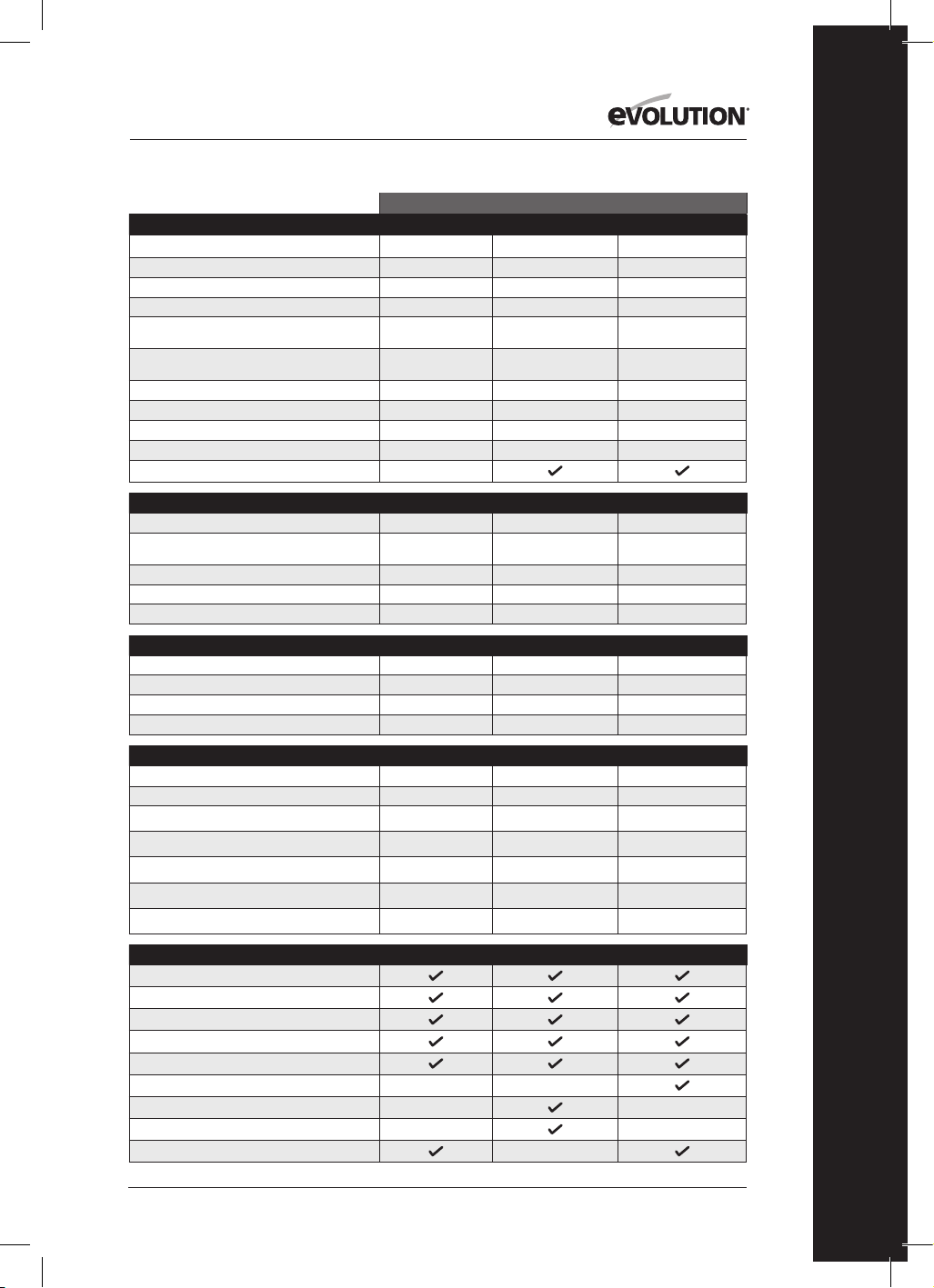
155
www.evolutionpowertools.com
PL
USA
SPECYFIKACJE URZĄDZENIA
R185CCS R185CCSX R185CCSX+
Numer modelu: 027-0004 027-0004C 027-0004A
Silnik EU (220-240 V ~ 50 Hz)
Silnik UK (110 V ~ 50 Hz)
Silnik USA (120V ~ 60 Hz) 15A 15A 15A
Prędkość bez obciążenia (220-240 V) 3700 min-1
/rpm
Prędkość bez obciążenia (110 V & 120 V) 3700
min-1 /rpm
3700 min
-1
/ rpm 3700 min
-1
/ rpm 3700 min
-1
/ rpm
Waga 10.8 lb 11.2 lb 11.2 lb
Maksymalny kąt nachylenia ostrza (stopnie) 60˚ 45˚ 45˚
Długość przewodu zasilania 3,96 m (13 stóp) 13 ft 13 ft 13 ft
Typ podstawy piły tarczowej Odlew aluminiowy Odlew aluminiowy Odlew aluminiowy
Kompatybilne prowadnice do cięcia
MOŻLIWOŚCI CIĘCIA R185CCS R185CCSX R185CCSX+
Arkusz z miękkiej stali (maksymalna grubość) 1/4” 1/4” 1/4”
Sekcja skrzynkowa z miękkiej stali (maksymalna
grubość ściany)
1/4” 1/4” 1/4”
Maksymalna grubość cięcia (0°) (z prowadnicą) 2-1/2”
2-1/2” (2-5/16” z prowadnicą) 2-1/2” (2-5/16” z prowadnicą)
Maksymalna grubość cięcia (45°) 1-9/16”
1-13/16” (1-5/8” z prowadnicą)
1-13/16” (1-5/8” z prowadnicą)
Maksymalna grubość cięcia (60°) 1”
WYMIARY TARCZY R185CCS R185CCSX R185CCSX+
Średnica tarczy Ø 7-1/4” Ø 7-1/4” Ø 7-1/4”
Liczba zębów 20 16 20
Średnica otworu 25/32” 25/32” 25/32”
Grubość 1.7mm 1.7mm 1.7mm
DANE DOT. HAŁASU I WIBRACJI R185CCS R185CCSX R185CCSX+
Poziom ciśnienia akustycznego L
pa
97,3dB(A) K=3 dB(A) 97,3dB(A) K=3 dB(A) 97,3dB(A) K=3 dB(A)
Poziom mocy akustycznej L
wa
105,3dB(A) K=3 dB(A) 105,3dB(A) K=3 dB(A) 105,3dB(A) K=3 dB(A)
Wibracje - główny uchwyt (piłowanie drewna)
A
h,w
= 3,347m/s
2
a
h,w
= 3,347m/s
2
a
h,w
= 3,347m/s
2
Wibracje - uchwyt pomocniczy (piłowanie drewna)
A
h,w
= 3,119m/s
2
a
h,w
= 3,119m/s
2
a
h,w
= 3,119m/s
2
Wibracje - główny uchwyt (piłowanie metalu)
a
h,M
= 3,572m/s
2
a
h,M
= 3,572m/s
2
a
h,M
= 3,572m/s
2
Wibracje - uchwyt pomocniczy (piłowanie metalu)
a
h,M
= 3,241m/s
2
a
h,M
= 3,241m/s
2
a
h,M
= 3,241m/s
2
Czynnik niepewności K
1,5m/s
2
1,5m/s
2
1,5m/s
2
ELEMENTY WYPOSAŻENIA R185CCS R185CCSX R185CCSX+
Ostrze TCT do wielu materiałów
Klucz imbusowy (wymiana ostrza)
Prowadnica równoległa
Adapter dyszy zasysającej pył
Adapter węża zasysającego pył
Futerał
Prowadnica do cięcia - 340 mm (13-3/8”) x 3
Listwa złącza i śruby (x4)
Oświetlenie LED
SPECYFIKACJE

156
www.evolutionpowertools.com
UK / EU / AUS
R165CCSL R185CCS R185CCSX R185CCSX+
026-0001 / 026-0002 /
026-0003
027-0001C /
027-0002C / 027-0003C
027-0001 /
027-0002 / 027-0003
027-0001A /
027-0002A / 027-0003A
1200W 1600W 1600W 1600W
1200W 1600W 1600W 1600W
3700 min
-1
/ rpm 3900 min
-1
/ rpm 3900 min
-1
/ rpm 3900 min
-1
/ rpm
3700 min
-1
/ rpm 3700 min
-1
/ rpm 3700 min
-1
/ rpm 3700 min
-1
/ rpm
4.3 kg 4.9 kg 5.1 kg 5.1 kg
45˚ 60˚ 45˚ 45˚
3m 3m 3m 4m
Tłoczona stal Odlew aluminiowy Odlew aluminiowy Odlew aluminiowy
R165CCSL R185CCS R185CCSX R185CCSX+
3mm 6mm 3mm 6mm
3mm 6mm 3mm 6mm
53mm 64mm
64mm (59mm z prowadnicą) 64mm (59mm z prowadnicą)
34mm 40mm
47mm (42mm z prowadnicą) 47mm (42mm z prowadnicą)
24mm
R165CCSL R185CCS R185CCSX R185CCSX+
Ø 165mm Ø 185mm Ø 185mm Ø 185mm
14 20 16 20
20mm 20mm 20mm 20mm
1.7mm 1.7mm 1.7mm 1.7mm
R165CCSL R185CCS R185CCSX R185CCSX+
92,4dB(A) K:3dB(A) 97,3dB(A) K=3 dB(A) 97,3dB(A) K=3 dB(A) 97,3dB(A) K=3 dB(A)
103,4dB(A) K:3dB(A) 105,3dB(A) K=3 dB(A) 105,3dB(A) K=3 dB(A) 105,3dB(A) K=3 dB(A)
a
h,w
= 2,747m/s
2
a
h,w
= 3,347m/s
2
a
h,w
= 3,347m/s
2
a
h,w
= 3,347m/s
2
a
h,w
= 2,619m/s
2
a
h,w
= 3,119m/s
2
a
h,w
= 3,119m/s
2
a
h,w
= 3,119m/s
2
a
h,M
= 2,302m/s
2
a
h,M
= 3,572m/s
2
a
h,M
= 3,572m/s
2
a
h,M
= 3,572m/s
2
a
h,M
= 2,239m/s
2
a
h,M
= 3,241m/s
2
a
h,M
= 3,241m/s
2
a
h,M
= 3,241m/s
2
1,5m/s
2
1,5m/s
2
1,5m/s
2
1,5m/s
2
R165CCSL R185CCS R185CCSX R185CCSX+
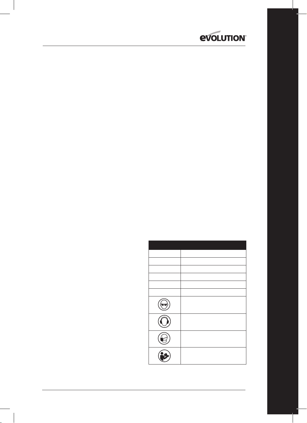
157
www.evolutionpowertools.com
PL
WIBRACJE
(1.5) Informacja: Pomiary wibracji zostały
wykonane w warunkach standardowych
zgodnych z: EN 62841-1: 2015,
EN 62841-2-5: 2014
Ostrzeżenie: Należy stosować środki ochrony
słuchu!
Podana wartość całkowita wibracji została
zmierzona zgodnie ze standardowymi metodami
testowymi i może posłużyć do porównywania
różnych narzędzi.
Podana wartość całkowita wibracji może także
posłużyć do wstępnej oceny narażenia.
(1.6) OSTRZEŻENIE: Podczas użytkowania tego
urządzenia operator może być narażony na wysoki
poziom wibracji przenoszonych na ręce i ramiona.
Istnieje możliwość rozwoju u operatora „choroby
wibracyjnej białych palców” (syndrom Raynauda).
Stan ten może zmniejszyć wrażliwość ręki na
temperaturę, jak
również powodować ogólne drętwienie.
W przypadku długotrwałego lub regularnego
korzystania z tego urządzenia należy dokładnie
monitorować stan dłoni i palców. W przypadku
pojawienia się jakichkolwiek objawów należy
zasięgnąć porady lekarza.
• Pomiar i ocena narażenia człowieka na drgania
przenoszone na dłonie w miejscu pracy są
podane w:
EN 62841-1, EN 62841-2-5
• Na poziom wibracji podczas pracy wpłynąć
może wiele czynników, np. stan i położenie
powierzchni roboczej oraz typ i stan używanej
maszyny. Czynniki te powinny zostać poddane
ocenie przed każdym użyciem. W miarę
możliwości należy zastosować odpowiednie
metody pracy. Ograniczenie wpływu
tych czynników może przyczynić się do
zmniejszenia skutków wibracji:
Obsługa
• Należy obsługiwać maszynę, zachowując
ostrożność i pozwalając urządzeniu
wykonywać powierzone zadanie.
• Należy unikać używania nadmiernej siły
fizycznej w odniesieniu do jakichkolwiek
elementów układu sterowania urządzeniem.
• Należy zwrócić uwagę na własne
bezpieczeństwo i stabilną pozycję,
a także na położenie maszyny podczas
użytkowania.
Powierzchnia robocza
• Należy zwrócić uwagę na materiał, z którego
wykonana jest powierzchnia robocza:
jego stan, gęstość, wytrzymałość,
sztywność i położenie.
OSTRZEŻENIE: Emisja drgań podczas
rzeczywistego użytkowania elektronarzędzia
może różnić się od podanej wartości całkowitej w
zależności od sposobu używania narzędzia.
Potrzeba ustalenia środków bezpieczeństwa i
ochrony operatora opiera się na ocenie narażenia
w rzeczywistych warunkach użytkowania (z
uwzględnieniem wszystkich etapów cyklu
operacyjnego, takich jak czas kiedy narzędzie jest
wyłączone, pracuje na biegu jałowym, w dodatku
do czasu aktywacji).
(1.7 ) OZNACZENIA I SYMBOLE
OSTRZEŻENIE: Nie należy korzystać z narzędzia
jeśli oznaczenia ostrzegawcze lub informacyjne
są uszkodzone lub zostały usunięte. Należy
skontaktować się z firmą Evolution Power Tools w
celu uzyskania nowych etykiet.
Uwaga: Wszystkie lub niektóre z następujących
symboli mogą znajdować się w instrukcji lub na
produkcie.
(1.8)
Symbol Opis
V
Wolty
A
Ampery
Hz
Herce
Min
-1
/ RPM
Prędkość
~
Prąd zmienny
n
o
Prędkość bez obciążenia
Należy stosować okulary
ochronne
Należy stosować środki
ochrony słuchu
Należy stosować ochronę
przed pyłem
Należy zapoznać się z instrukcją
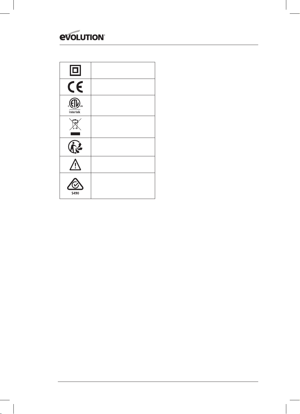
158
www.evolutionpowertools.com
Podwójna izolacja
Certykat CE
Certykat ETL
Zużyty sprzęt elektryczny
i elektroniczny
Triman - zbieranie odpadów
i recykling
Ostrzeżenie
Oznaczenie zgodności z przepisami
dla sprzętów elektrycznych i
elektronicznych (RCM). Standard w
Australii i Nowej Zelandii
(1.9) PRZEWIDZIANE ZASTOSOWANIE
ELEKTRONARZĘDZIA
OSTRZEŻENIE: Niniejszy produkt to ręczna
pilarka tarczowa zaprojektowana do eksploatacji
z wykorzystaniem specjalnych tarcz marki
Evolution. Należy używać wyłącznie akcesoriów
zaprojektowanych do stosowania z tym
narzędziem i/lub akcesoriów zalecanych przez
Evolution Power Tools Ltd.
Po zamontowaniu odpowiedniego ostrza
narzędzie to można przeznaczyć do cięcia:
Stali miękkiej
Aluminium
Drewna
Uwaga: Cięcie stali ocynkowanej może skrócić
żywotność ostrza.
(1.10) ZABRONIONE ZASTOSOWANIE
ELEKTRONARZĘDZIA
OSTRZEŻENIE: Ręcznej pilarki tarczowej należy
używać wyłącznie zgodnie z przeznaczeniem.
Nie należy wprowadzać w urządzeniu żadnych
modyfikacji ani stosować urządzenia do zasilania
jakichkolwiek urządzeń lub akcesoriów innych niż
określone w niniejszej instrukcji.
(1.11) OSTRZEŻENIE: Urządzenie nie jest
przeznaczone do użytkowania przez osoby
(w tym dzieci) o ograniczonej sprawności
fizycznej, sensorycznej lub umysłowej lub
braku doświadczenia i wiedzy, chyba że będą
one nadzorowane lub zostaną poinstruowane
na temat bezpiecznego korzystania z
urządzenia przez osobę odpowiedzialną za ich
bezpieczeństwo i potrafiącą obsłużyć narzędzie w
bezpieczny sposób.
Dzieci wymagają stałego nadzoru, aby z całą
pewnością, nie miały one dostępu do sprzętu, ani
pozwolenia na zabawę urządzeniem.
(1.12) BEZPIECZEŃSTWO ELEKTRYCZNE
Urządzenie jest wyposażone w odpowiednio
profilowaną wtyczkę i kabel zasilający odpowiedni
dla danego rynku. W przypadku uszkodzenia
kabla zasilającego, należy go wymienić na
specjalny kabel lub zespół dostępny u producenta
lub autoryzowanego dystrybutora.
(1.13) UŻYTKOWANIE NA ZEWNĄTRZ
OSTRZEŻENIE: W przypadku korzystania z
urządzenia na wolnym powietrzu, ze względów
bezpieczeństwa, nie należy używać go w
miejscach zawilgoconych ani narażać na działanie
deszczu. Nie należy umieszczać narzędzia na
wilgotnej powierzchni. W miarę możliwości należy
ustawić je na czystym i suchym blacie roboczym.
W celu zapewnienia dodatkowej ochrony należy
zastosować wyłącznik różnicowoprądowy (RCD),
który przerwie zasilanie, jeśli prąd różnicowy
przekroczy 30 mA przez okres 30 ms. Przed
przystąpieniem do korzystania z urządzenia
należy zawsze sprawdzić działanie wyłącznika
różnicowoprądowego (RCD).
W przypadku konieczności zastosowania
przedłużacza, należy upewnić się, że nadaje się on
do używania na zewnątrz i posiada odpowiednie
oznaczenie. Podczas korzystania z przedłużacza
należy przestrzegać instrukcji producenta.
(2.1) OGÓLNE INSTRUKCJE
BEZPIECZEŃSTWA
(Niniejsze ogólne instrukcje bezpieczeństwa przy
korzystaniu z elektronarzędzi są zgodne z BS EN
60745-1:2009, EN 61029-1:2009 & EN 62847-
1:2015).
OSTRZEŻENIE: Należy zapoznać się z
treścią wszelkich ostrzeżeń oraz instrukcji.
Nieprzestrzeganie ostrzeżeń lub instrukcji może
doprowadzić do porażenia prądem, pożaru i/lub
poważnych obrażeń.
Wszystkie ostrzeżenia i instrukcje należy
zachować w celu przyszłego wykorzystania.
Termin „elektronarzędzie” odnosi się do

159
www.evolutionpowertools.com
PL
urządzenia zasilanego sieciowo (przewodowego)
lub urządzenia zasilanego za pomocą baterii
(bezprzewodowego).
(2.2) 1) Ogólne ostrzeżenia w zakresie
bezpieczeństwa elektronarzędzi
[Bezpieczeństwo obszaru roboczego]
a) Należy zadbać o czystość i prawidłowe
oświetlenie obszaru pracy.
Zanieczyszczenie lub brak wystarczającego
oświetlenia obszaru pracy mogą doprowadzić do
wypadków.
b) Nie należy używać elektronarzędzi w
przestrzeniach zagrożonych wybuchem, np.
w obecności łatwopalnych cieczy, gazów lub
pyłów. Elektronarzędzia wytwarzają iskry, które
mogą spowodować zapłon pyłu lub oparów.
c) Nie należy dopuszczać dzieci ani
innych obserwatorów do obszaru pracy
elektronarzędzi. Rozproszenie uwagi może
spowodować utratę kontroli.
(2.3) 2) Ogólne ostrzeżenia w zakresie
bezpieczeństwa elektronarzędzi
[Bezpieczeństwo elektryczne]
a) Wtyczka elektronarzędzia musi być zgodna
z gniazdem zasilania. Nie wolno w żaden
sposób modyfikować wtyczki. W przypadku
elektronarzędzi z uziemieniem nie należy
stosować przejściówek. Oryginalne wtyczki i
zgodne gniazda zmniejszają ryzyko porażenia
prądem.
b) Należy unikać dotykania uziemionych
powierzchni, takich jak rury, grzejniki, piece i
lodówki. Uziemienie ciała powoduje zwiększenie
ryzyka porażenia prądem.
c) Nie należy wystawiać elektronarzędzi na
działanie deszczu lub wilgoci. Przedostanie
się wody do wnętrza urządzenia zwiększa ryzyko
porażenia prądem.
d) Nie należy nadwyrężać przewodu. Nigdy
nie należy używać przewodu do przenoszenia,
przeciągania lub odłączania elektronarzędzia.
Przewód należy trzymać z dala od źródeł ciepła,
oleju, ostrych krawędzi lub ruchomych części
urządzenia. Uszkodzone lub poplątane przewody
zwiększają ryzyko porażenia prądem.
e) W przypadku korzystania z urządzenia
na wolnym powietrzu należy używać
przedłużacza przystosowanego do używania
na zewnątrz. Korzystanie z przedłużacza
przystosowanego do używania na zewnątrz
zmniejsza ryzyko porażenia prądem.
f) W przypadku korzystania z elektronarzędzia
w miejscu o dużym natężeniu wilgoci należy
używać gniazda zasilania wyposażonego w
wyłącznik różnicowoprądowy (RCD).
Korzystanie z wyłącznika różnicowoprądowego
zmniejsza ryzyko porażenia prądem.
Uwaga: Produkt jest przeznaczony do użytku
jedynie w pomieszczeniach o wydajności prądu
eksploatacyjnego ≥ 100 A na fazę, zasilanych z
sieci dystrybucyjnej o napięciu znamionowym
230 V. W razie potrzeby należy skontaktować się
z zakładem energetycznym, aby upewnić się,
że nośność prądu w punkcie przyłączenia do
publicznej sieci energetycznej jest odpowiednia
do podłączenia produktu.
(2.4) 3) Ogólne ostrzeżenia w zakresie
bezpieczeństwa elektronarzędzi
[Bezpieczeństwo osobiste].
a) Podczas korzystania z elektronarzędzia
użytkownik powinien być czujny, uważny i
zachowywać zdrowy rozsądek. Nie należy
używać elektronarzędzi w stanie zmęczenia bądź
pod wpływem narkotyków, alkoholu lub leków.
Chwila nieuwagi podczas obsługi urządzenia
może spowodować poważne obrażenia ciała.
b) Należy korzystać ze środków ochrony
osobistej. Należy zawsze stosować środki
ochrony oczu. Wyposażenie ochronne, takie
jak maska przeciwpyłowa, obuwie robocze
antypoślizgowe, kask ochronny lub nauszniki
ochronne używane w odpowiednich warunkach
zmniejszają ryzyko poniesienia obrażeń.
c) Należy zapobiegać przypadkowemu
włączeniu urządzenia. Przed podłączeniem
do źródła zasilania i/lub akumulatora,
podnoszeniem lub przenoszeniem
narzędzia, należy upewnić się, że przełącznik
zasilania znajduje się w pozycji wyłączonej.
Przenoszenie urządzenia z palcem umieszczonym
na przełączniku zasilania lub podłączanie
elektronarzędzi przy włączonym przełączniku
zasilania stwarza ryzyko wypadku.
d) Przed włączeniem elektronarzędzia należy
usunąć z niego wszelkie narzędzia oraz klucze
regulacyjne. Narzędzie lub klucz pozostawiony
w obracającej się części elektronarzędzia może
spowodować obrażenia ciała.
e) Nie należy się wychylać. W każdej chwili
należy zachowywać odpowiednią pozycję i
równowagę ciała. Umożliwia to lepszą kontrolę
nad elektronarzędziem w nieoczekiwanych
sytuacjach.
f) Należy nosić odpowiednią odzież. Do pracy
z elektronarzędziem nie należy zakładać luźnej
odzieży ani biżuterii. Włosy, odzież i rękawice
należy trzymać z dala od ruchomych części
urządzenia. Ubranie, biżuteria lub długie włosy
mogą zostać wciągnięte przez ruchome części
urządzenia.
g) Jeśli do zestawu załączone są urządzenia
do podłączenia mechanizmów odsysania
i zbierania pyłu, należy sprawdzić, czy są
one przyłączone i prawidłowo zamocowane.

160
www.evolutionpowertools.com
Korzystanie z urządzenia odsysającego pył może
zmniejszyć zagrożenie związane z pyłami.
h) Nie należy pozwolić, aby obeznanie
związane z częstym korzystaniem z urządzenia
doprowadziło do beztroski i ignorowania
zasad bezpieczeństwa. Nieprzemyślane działanie
może spowodować poważne obrażenia w ułamku
sekundy.
(2.5) 4) Ogólne ostrzeżenia w zakresie
bezpieczeństwa elektronarzędzi [Eksploatacja
i pielęgnacja elektronarzędzi].
a) Nie należy przeciążać urządzenia. Należy
używać narzędzi odpowiednich dla danego
zastosowania. Prawidłowe narzędzie wykona
zadanie lepiej i bezpieczniej w podanym zakresie
sprawności.
b) Nie używać urządzenia, jeśli przełącznik
nie spełnia funkcji włączania ub wyłączania
urządzenia. Urządzenia,których nie można
kontrolować za pomocą przełącznika, są
niebezpieczne i muszą zostać oddane do naprawy.
c) Przed dokonaniem regulacji, wymiany
akcesoriów lub przechowywaniem
elektronarzędzia należy odłączyć wtyczkę
od źródła zasilania i/lub akumulator od
urządzenia. Prewencyjne środki bezpieczeństwa
zmniejszają ryzyko przypadkowego uruchomienia
elektronarzędzia.
d) Nieużywane elektronarzędzia należy
przechowywać w miejscu niedostępnym dla
dzieci i nie należy dopuszczać do nich osób
nie zaznajomionych z obsługą elektronarzędzi
lub treścią instrukcji obsługi. Elektronarzędzia
stanowią niebezpieczeństwo w rękach
niedoświadczonych użytkowników.
e) Należy przeprowadzać konserwację
elektronarzędzi. Należy sprawdzać urządzenie
pod kątem nieprawidłowego ustawienia lub
zablokowania elementów ruchomych, pęknięć
elementów ruchomych lub innych usterek, które
mogą wpłynąć na funkcjonowanie urządzenia.
W przypadku usterki urządzenie należy naprawić
przed ponownym użyciem. Niewłaściwa
konserwacja elektronarzędzi jest przyczyną wielu
wypadków.
f) Należy utrzymywać narzędzia tnące w
czystości i pamiętać o ich ostrzeniu.
Zadbane narzędzia tnące z ostrymi krawędziami
tnącymi rzadziej się zacinają i łatwiej nimi
sterować.
g) Należy używać elektronarzędzia,
akcesoriów, końcówek itp. zgodnie z niniejszymi
instrukcjami, biorąc pod uwagę warunki pracy
i wykonywane zadania. Używanie narzędzi
do wykonywania prac niezgodnych z ich
przeznaczeniem
może doprowadzić do niebezpiecznych sytuacji.
h) Uchwyty i powierzchnie chwytne muszą
być suche, czyste i niezanieczyszczone olejem
ani smarem. Śliskie uchwyty i powierzchnie
uniemożliwiają bezpieczną obsługę i kontrolę
urządzenia w nieprzewidzianych sytuacjach.
(2.6) 5) Ogólne ostrzeżenia w zakresie
bezpieczeństwa elektronarzędzi
[Serwis]
a) Urządzenie powinno być serwisowane
przez wykwalifikowaną osobę przy użyciu
wyłącznie identycznych części zamiennych.
Zagwarantuje to utrzymanie bezpieczeństwa
elektronarzędzia.
(2.7) ZALECENIA ZDROWOTNE
OSTRZEŻENIE: Przy korzystaniu z urządzenia
mogą wytworzyć się cząsteczki pyłu. W niektórych
przypadkach, w zależności od wykorzystywanych
materiałów, pył może być szczególnie szkodliwy.
W przypadku podejrzenia, że farba pokrywająca
powierzchnię ciętego materiału zawiera ołów,
należy zasięgnąć porady specjalisty. Farby na
bazie ołowiu powinny zostać usunięte jedynie
przez profesjonalistę i nie należy podejmować
samodzielnych prób ich usuwania. Po osadzeniu
się pyłu na powierzchniach, przeniesienie go
dłońmi do jamy ustnej może doprowadzić do
spożycia ołowiu. Narażenie na choćby niewielką
ilość ołowiu może spowodować nieodwracalne
uszkodzenie mózgu i systemu nerwowego.
Szczególnie narażone są małe i nienarodzone
dzieci. Zaleca się ocenę ryzyka związanego
z obróbką danego materiału i ograniczenie
narażenia się na szkodliwe czynniki.
Niektóre materiały mogą produkować pyły
szkodliwe dla zdrowia. Podczas korzystania z
urządzenia zalecamy stosowanie zatwierdzonych
masek przeciwpyłowych z wymiennymi filtrami.
Należy zawsze:
• pracować w dobrze wentylowanym
miejscu.
• korzystać z zatwierdzonych środków
bezpieczeństwa, takich jak maski
przeciwpyłowe, zaprojektowane specjalnie po
to, aby filtrować mikroskopijne cząsteczki.
(2.8) OSTRZEŻENIE: podczas korzystania z
dowolnego elektronarzędzia ciała obce mogą
zostać wyrzucone w kierunku oczu operatora,
co może skutkować poważnym urazem narządu
wzroku. Przed przystąpieniem do pracy z
elektronarzędziem należy założyć okulary lub
gogle ochronne z osłoną boczną. W miarę
potrzeby należy zastosować całkowitą osłonę
twarzy.

161
www.evolutionpowertools.com
PL
INSTRUKCJE BEZPIECZEŃSTWA DLA
WSZYSTKICH PILAREK
[Postępowanie przy cięciu]
a) ZAGROŻENIE: Dłonie należy trzymać z dala
od ciętej powierzchni i ostrza. Drugą rękę należy
trzymać na uchwycie pomocniczym lub na
obudowie silnika . Jeśli obie ręce będą trzymać
pilarkę, nie dostaną się pod ostrze.
b) Nie należy sięgać pod obrabiany przedmiot.
Osłona ostrza nie chroni operatora pod
obrabianym przedmiotem.
c) Głębokość cięcia należy dostosować do
grubości obrabianego przedmiotu. Poniżej
obrabianego przedmiotu widoczny być powinien
jeden niepełny ząb tarczy.
d) Podczas cięcia nie wolno trzymać
obrabianego przedmiotu w dłoniach lub
opierać go na nodze . Przedmiot należy
zabezpieczyć na stabilnej podstawie. Należy
odpowiednio zabezpieczyć pracę, aby
zminimalizować prawdopodobieństwo
zablokowania ostrza, utraty kontroli lub narażenia
ciała na obrażenia.
e) Podczas wykonywania zadania, w którym
narzędzie tnące może natrafić na ukryte
przewody elektryczne lub na własny przewód,
należy trzymać urządzenie za izolowane
powierzchnie chwytne. Natrafienie na kabel,
który jest pod napięciem, przenosi napięcie
na metalowe części elektronarzędzia i może
doprowadzić do porażenia operatora prądem.
f) Podczas cięcia wzdłuż, należy zawsze
korzystać z przykładnicy lub prowadnicy.
Zapewnia to dokładność cięcia i zmniejsza
prawdopodobieństwo zablokowania ostrza.
g) Należy zawsze używać tarcz o odpowiednim
rozmiarze i kształcie otworu mocowania
(romb lub okrągły). Ostrza niepasujące do
osprzętu montażowego piły mogą spowodować
nieprawidłowe obroty tarczy i utratę kontroli.
h) Nie wolno używać śrub i podkładek, które są
zniszczone lub nieprawidłowe. Podkładki i śruba
zostały zaprojektowane specjalnie do tej pilarki
dla optymalnej efektywności i bezpieczeństwa
pracy.
(3.2) [Przyczyny odrzutu i powiązane z tym
ostrzeżenia]
Odrzut to nagła reakcja na zakleszczenie,
zablokowanie lub nieprawidłowe ustawienie
ostrza, powodujące niekontrolowane odrzucenie
ostrza z obrabianego materiału i przesunięcie się
w stronę operatora.
Jeśli tarcza zakleszczy się lub zablokuje poprzez
zamknięcie nacięcia, ostrze traci sterowność,
a silnik reaguje gwałtownym odrzuceniem
urządzenia w stronę operatora.
Jeśli ostrze wygnie się lub ustawi się
nieprawidłowo w nacięciu, zęby na tylnej
krawędzi tarczy mogą wbić się w górną warstwę
drewna, powodując wydostanie się ostrza z
nacięcia i odrzut w stronę operatora.
(3.3) Odrzut jest efektem nieprawidłowego użycia
pilarki i/lub nieprawidłowego postępowania lub
warunków pracy. Można go uniknąć stosując
środki prewencyjne opisane poniżej.
a) Urządzenie należy trzymać stabilnie obiema
rękami w odpowiedniej pozycji, która pozwoli
na odparcie siły odrzutu. Należy ustawić się
po dowolnej stronie tarczy, a nie na równi z nią.
Odrzut powoduje odskoczenie urządzenia do tyłu,
lecz siła odrzutu może być kontrolowana przez
operatora, jeśli podjęte są odpowiednie środki
prewencyjne.
b) Jeśli ostrze się blokuje lub zakłóca cięcie
z dowolnego powodu, należy zwolnić
przełącznik i trzymać pilarkę bez ruchu
w materiale aż do momentu, kiedy tarcza
całkowicie się zatrzyma. W żadnym wypadku
nie należy podejmować próby usunięcia pilarki
z obrabianego przedmiotu lub pociągnięcia jej
do tyłu, podczas gdy tarcza jest w ruchu. Może to
doprowadzić do odrzutu. Należy przeanalizować
i podjąć działania korekcyjne, aby wyeliminować
przyczynę zablokowywania się ostrza.
c) Przywracając pilarkę do pracy nad
przedmiotem obróbki, ustaw ostrze w
nacięciu, tak aby zęby nie wchodziły w
materiał. Jeśli ostrze się zablokuje, może
wspiąć się do góry lub spowodować odrzut od
przedmiotu obróbki przy restarcie pilarki.
d) Nie należy używać tępych lub zniszczonych
tarcz. Nienaostrzone lub nieprawidłowo założone
tarcze mogą stworzyć zbyt wąskie nacięcie,
powodując nadmierne tarcie, blokowanie się
ostrza i odrzut.
e) Dźwignie blokady głębokości i nachylenia
ostrza muszą być sztywnie zablokowane przed
przystąpieniem do cięcia. Zmiana ustawień
ostrza podczas cięcia może spowodować
zablokowanie i odrzut.
f) Dźwignie blokady głębokości i nachylenia
ostrza muszą być sztywnie zablokowane przed
przystąpieniem do cięcia. Zmiana ustawień
ostrza podczas cięcia może spowodować
zablokowanie i odrzut.
g) Należy zachować szczególną uwagę przy
użyciu piły do cięcia istniejących ścian lub
martwego pola. Wystające ostrze może ciąć
obiekty, które mogą spowodować odrzut.

162
www.evolutionpowertools.com
FUNKCJA DOLNEJ OSŁONY
a) Przed każdym użyciem należy sprawdzić,
czy dolna osłona prawidłowo się domyka. Nie
należy używać pilarki, jeśli dolna osłona nie
porusza się swobodnie i nie zamyka się od
razu. W żadnym wypadku nie należy zaciskać ani
przywiązywać dolnej osłony w otwartej pozycji.
Przy przypadkowym upuszczeniu pilarki dolna
osłona może się wygiąć. Dolną osłonę należy
unieść przy pomocy dźwigni i upewnić się, że
porusza się swobodnie i że nie dotyka ostrza lub
innej części urządzenia, niezależnie od kąta czy
głębokości cięcia.
b) Należy sprawdzić działanie sprężyny osłony
dolnej. Jeśli osłona i sprężyna nie działają
prawidłowo, muszą zostać oddane do naprawy
przed ponownym użyciem. Dolna osłona może
działać powoli z powodu zniszczonych części lub
zebrania się lepkich osadów i resztek materiałów.
c) Dolna osłona może zostać wycofana
ręcznie tylko w przypadku wykonywania
specjalnych cięć, takich jak „cięcie wgłębne” i
„cięcie złożone”. Należy unieść dolną osłonę
przy pomocy dźwigni. W momencie, gdy
ostrze wejdzie w materiał, osłona musi zostać
spuszczona. Przy innych cięciach dolna osłona
powinna działać automatycznie.
d) Przed położeniem pilarki na ławie
warsztatowej lub podłodze należy zwrócić
uwagę, czy dolna osłona zakrywa ostrze.
Nieosłonięte, dryfujące ostrze spowoduje
wycofywanie się pilarki i cięcie przez nią
wszystkiego, co napotka na swojej drodze. Należy
być świadomym okresu czasu wymaganego na
zatrzymanie się ostrza od momentu zwolnienia
przełącznika.
DODATKOWE INSTRUKCJE
BEZPIECZEŃSTWA
DLA PIŁ TARCZOWYCH
a) Nie należy używać ostrzy wyprodukowanych
ze stali szybkotnącej (HSS).
b) Przed każdym użyciem należy skontrolować
maszynę i ostrze. Nie należy używać
zdeformowanych, pękniętych, zużytych lub
zniszczonych w inny sposób ostrzy.
c) W żadnym wypadku nie należy używać
pilarki pozbawionej oryginalnego
ochronnego systemu osłony. Nie należy
blokować ruchomej osłony w otwartej pozycji.
Należy upewnić się, że osłona działa swobodnie i
nie blokuje się.
d) Należy używać jedynie tarczy zgodnych z
opisem zawartym w niniejszej instrukcji. Zanim
skorzystasz z akcesoriów należy zawsze porównać
maksymalną dozwoloną częstotliwość obrotu
(obr/min) akcesorium z częstotliwością obrotu
(obr/min) urządzenia.
e) Nie należy używać tarcz ściernych.
f) Należy używać jedynie tarcz, których
średnica zgodna jest z oznaczeniami.
(3.4)OSTRZEŻENIE: W przypadku braku
jakichkolwiek części urządzenia nie należy
go uruchamiać aż do momentu uzupełnienia
brakujących komponentów. Nie przestrzeganie
tego zalecenia może powodować poważne
obrażenia ciała.
(4.1) PRZYGOTOWANIE DO PRACY -
ROZPAKOWANIE
Uwaga: Opakowanie zawiera ostre przedmioty.
Podczas rozpakowywania należy zachować
ostrożność. Urządzenie wraz z załączonymi
akcesoriami należy wyjąć z opakowania. Należy
dokładnie sprawdzić, czy urządzenie jest w
dobrym stanie i potwierdzić obecność wszystkich
akcesoriów wymienionych w instrukcji obsługi.
Należy również upewnić się, czy w żadnym z
akcesoriów nie brakuje komponentów.
W przypadku braku jakiegokolwiek komponentu
należy zwrócić urządzenie wraz z akcesoriami i w
oryginalnym opakowaniu do dystrybutora.
Nie wyrzucać opakowania. Opakowanie należy
zachować na czas trwania okresu gwarancyjnego.
Opakowanie należy zutylizować w sposób
przyjazny dla środowiska. W miarę możliwości
należy poddać je recyklingowi.
Nie należy zezwalać dzieciom na zabawę
torebkami foliowymi ze względu na ryzyko
uduszenia.
(4.3) INSTRUKCJA OBSŁUGI
EVOLUTION
Do każdego produktu firmy Evolution Power Tools
załączona jest instrukcja obsługi.Każda instrukcja
poświęcona danemu produktowi stworzona jest z
uwagą w celu ułatwienia dostępu do przydatnych
informacji dotyczących bezpiecznego użycia,
pielęgnacji i konserwacji produktu. Kierowanie
się informacjami zawartymi w niniejszej instrukcji
pozwoli operatorowi na pełne i bezpieczne
wykorzystanie potencjału urządzenia.
Polityka nieustającego rozwoju produktów firmy
Evolution może w rzadkich przypadkach wpłynąć
na fakt, że informacje zawarte w instrukcji mogą
różnić się od ostatnich aktualizacji i usprawnień
wprowadzonych do danego produktu. Zmiany
w specyfikacji tego produktu mogą być
konsekwencją rozwoju technologicznego i
zmian w ramach prawnych danego kraju, itp.
Jeśli którykolwiek z aspektów użytkowania,
pielęgnacji i konserwacji produktu Evolution
wzbudza wątpliwości, należy skontaktować się z
odpowiednią infolinią Evolution w celu uzyskania
aktualnych informacji i dodatkowej porady.

163
www.evolutionpowertools.com
PL
USA
1. WYRZUTNIK TROCIN
2. DŹWIGNIA
3. OSTRZE TCT DO WIELU MATERIAŁÓW
4. DOLNA OSŁONA OSTRZA
5. PROWADNICA RÓWNOLEGŁA
6. ERGONOMICZNY UCHWYT PRZEDNI
7. SZCZOTKI WĘGLOWE
8. KLUCZ IMBUSOWY (WYMIANA OSTRZA)
9. DŹWIGNIA BLOKADY USTAWIENIA
GŁĘBOKOŚCI
10. MIERNIK GŁĘBOKOŚCI
11. TYLNY UCHWYT Z BEZPIECZNYM
PRZEŁĄCZNIKIEM ON/OFF
12. GÓRNA OSŁONA OSTRZA
13. PRECYZYJNIE SKONTRUOWANA PODSTAWA
14. DŹWIGNIA
15. PODZIAŁKA KĄTOMIERZA
16. PRZYCISK BLOKADY TRZPIENIA
17. OŚWIETLENIE LED
18. ZŁĄCZE PORTU DO ZASYSANIA PYŁU
19. KOŁNIERZ WEWNĘTRZNY 25/32”
20. KOŁNIERZ WEWNĘTRZNY 5/8”
13
15
17
18
19
20
4
14
5
1
3
8
9
10
11
6
7
2
16
12
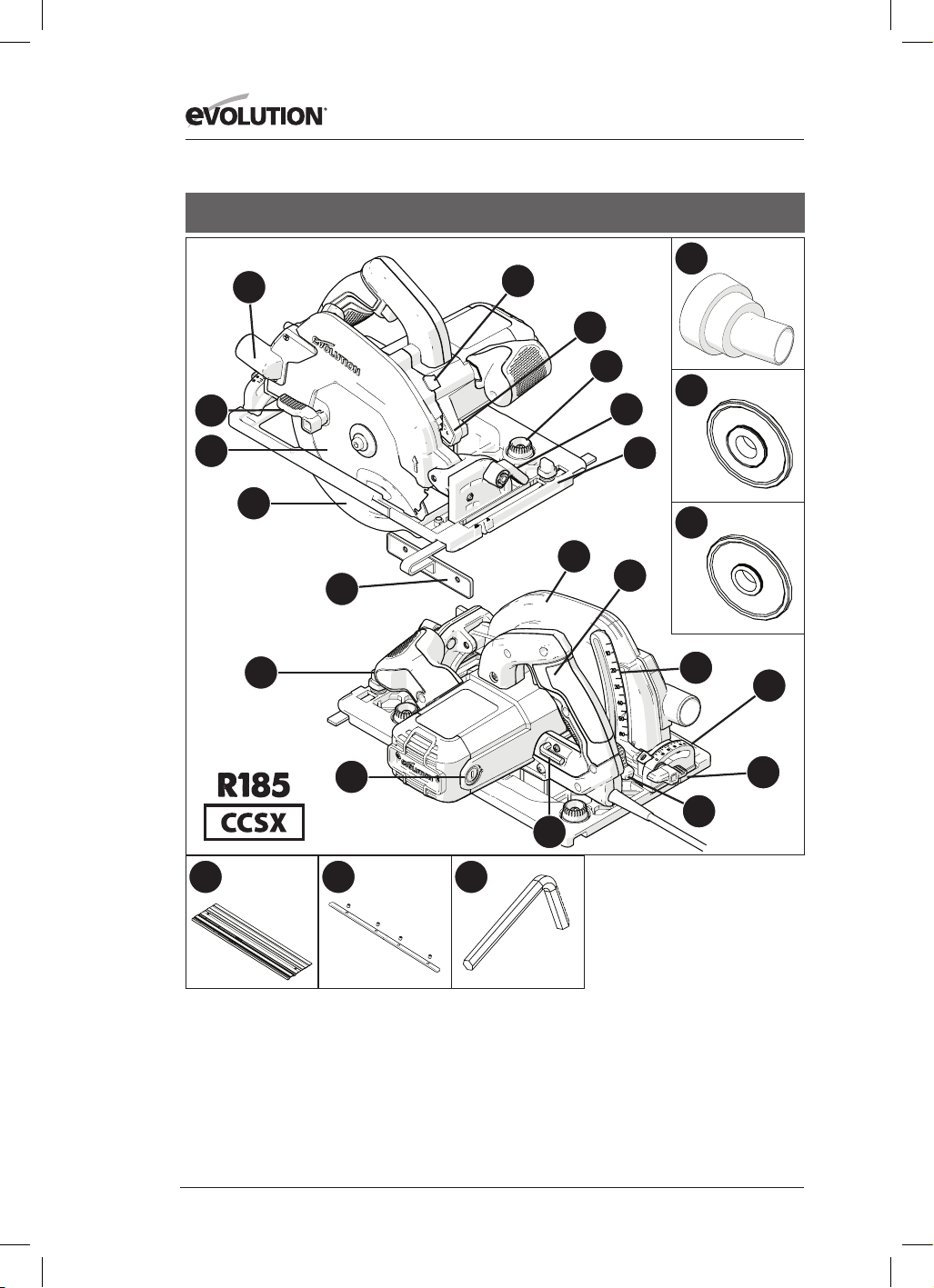
164
www.evolutionpowertools.com
USA
1. WYRZUTNIK TROCIN
2. DŹWIGNIA
3. OSTRZE TCT DO WIELU
MATERIAŁÓW
4. DOLNA OSŁONA OSTRZA
5. PROWADNICA RÓWNOLEGŁA
6. ERGONOMICZNY UCHWYT
PRZEDNI
7. SZCZOTKI WĘGLOWE
8. KLUCZ IMBUSOWY (WYMIANA
OSTRZA)
9. DŹWIGNIA BLOKADY
USTAWIENIA GŁĘBOKOŚCI
10. MIERNIK GŁĘBOKOŚCI
11. TYLNY UCHWYT Z BEZPIECZNYM
PRZEŁĄCZNIKIEM ON/OFF
12. GÓRNA OSŁONA OSTRZA
13. PRECYZYJNIE SKONTRUOWANA
PODSTAWA
14. DŹWIGNIA
15. PODZIAŁKA KĄTOMIERZA
16. PRZYCISK BLOKADY TRZPIENIA
17. OŚWIETLENIE LED
18. ZŁĄCZE PORTU DO ZASYSANIA
PYŁU
19. KOŁNIERZ WEWNĘTRZNY 25/32”
20. KOŁNIERZ WEWNĘTRZNY 5/8”
21. PRZYCISKI ZMIANY REGULACJI
PROWADNICY
22. ŚRUBA MOTYLKOWA TYLNEGO
ZACIOSU
23. PROWADNICA 3x 13 - 3/8”
24. 4 x PASKI ZŁĄCZA PROWADNICY
25. KLUCZ IMBUSOWY 1/8”
(PROWADNICA)
13
21
15
17
18
19
20
4
14
5
1
3
8
9
10
22
11
6
7
2
16
12
23 24
25

165
www.evolutionpowertools.com
PL
USA
1. WYRZUTNIK TROCIN
2. DŹWIGNIA
3. OSTRZE TCT DO WIELU MATERIAŁÓW
4. DOLNA OSŁONA OSTRZA
5. PROWADNICA RÓWNOLEGŁA
6. ERGONOMICZNY UCHWYT PRZEDNI
7. SZCZOTKI WĘGLOWE
8. KLUCZ IMBUSOWY (WYMIANA OSTRZA)
9. DŹWIGNIA BLOKADY USTAWIENIA
GŁĘBOKOŚCI
10. MIERNIK GŁĘBOKOŚCI
11. TYLNY UCHWYT Z BEZPIECZNYM
PRZEŁĄCZNIKIEM ON/OFF
12. GÓRNA OSŁONA OSTRZA
13. PRECYZYJNIE SKONTRUOWANA PODSTAWA
14. DŹWIGNIA
15. PODZIAŁKA KĄTOMIERZA
16. PRZYCISK BLOKADY TRZPIENIA
17. OŚWIETLENIE LED
18. ZŁĄCZE PORTU DO ZASYSANIA PYŁU
19. KOŁNIERZ WEWNĘTRZNY 25/32”
20. KOŁNIERZ WEWNĘTRZNY 5/8”
21. PRZYCISKI ZMIANY REGULACJI
PROWADNICY
22. ŚRUBA MOTYLKOWA TYLNEGO ZACIOSU
13
21
15
17
18
19
20
4
14
5
1
3
8
9
10
22
11
6
7
2
16
12
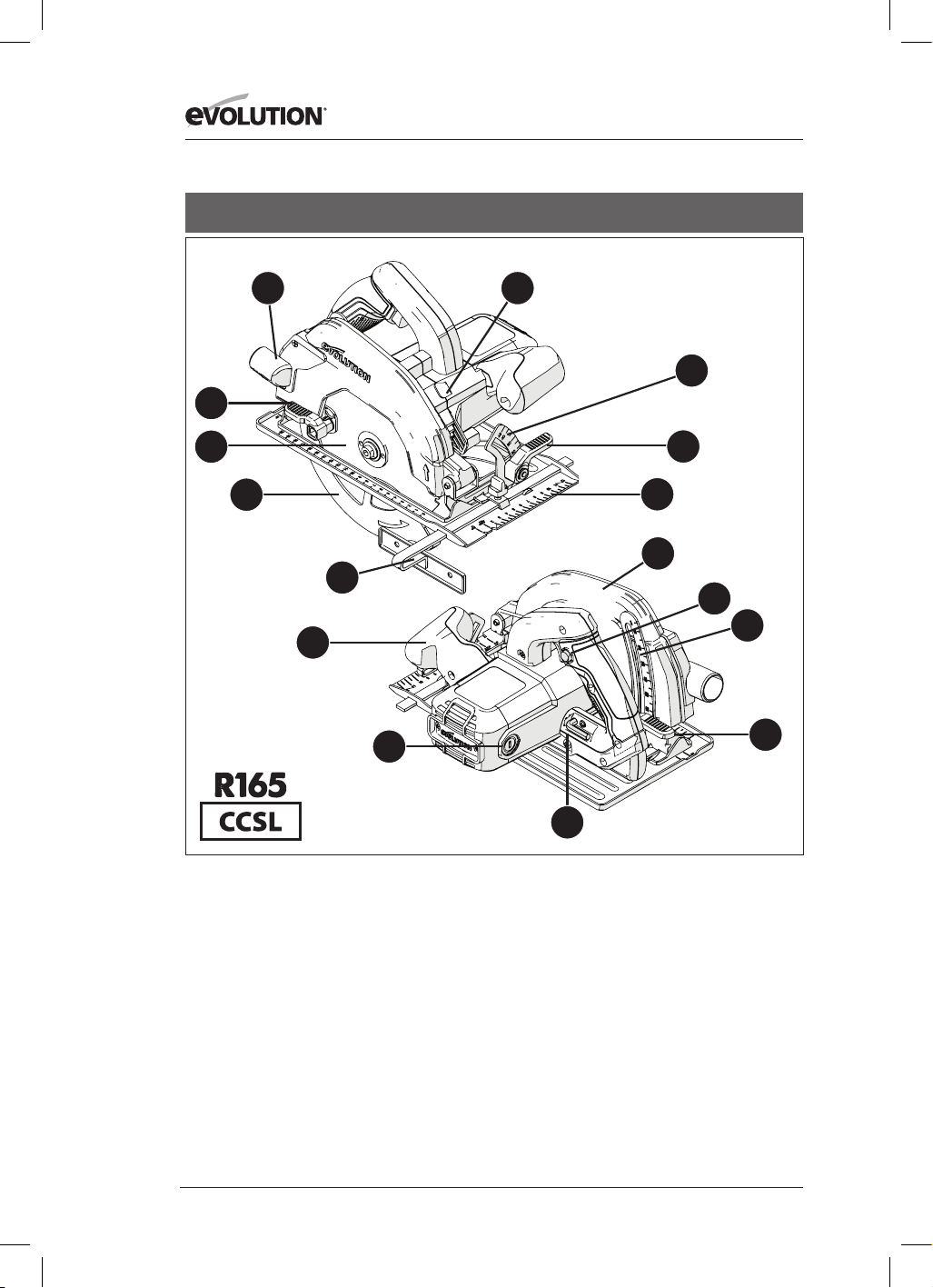
166
www.evolutionpowertools.com
13
15
4
14
5
1
3
8
9
10
11
6
7
2
16
12
1. WYRZUTNIK TROCIN
2. DŹWIGNIA
3. OSTRZE TCT DO WIELU MATERIAŁÓW
4. DOLNA OSŁONA OSTRZA
5. PROWADNICA RÓWNOLEGŁA
6. ERGONOMICZNY UCHWYT PRZEDNI
7. SZCZOTKI WĘGLOWE
8. KLUCZ IMBUSOWY (WYMIANA OSTRZA)
9. DŹWIGNIA BLOKADY USTAWIENIA
GŁĘBOKOŚCI
10. MIERNIK GŁĘBOKOŚCI
11. TYLNY UCHWYT Z BEZPIECZNYM
PRZEŁĄCZNIKIEM ON/OFF
12. GÓRNA OSŁONA OSTRZA
13. PRECYZYJNIE SKONTRUOWANA PODSTAWA
14. DŹWIGNIA
15. PODZIAŁKA KĄTOMIERZA
16. PRZYCISK BLOKADY TRZPIENIA
UK / EU / AUS
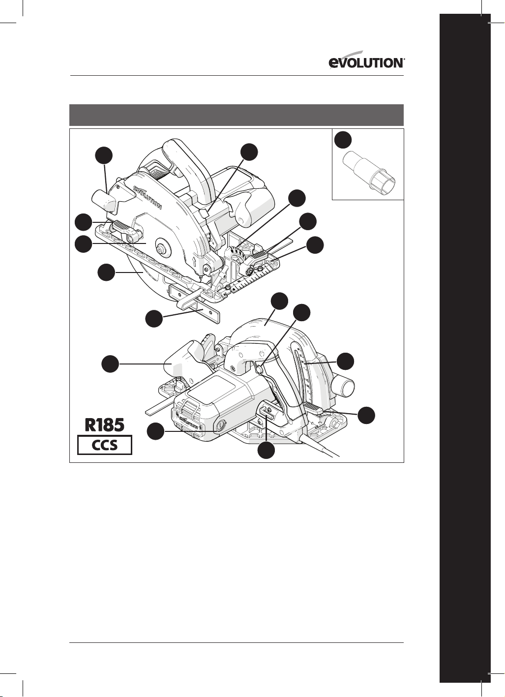
167
www.evolutionpowertools.com
PL
UK / EU
13
15
17
4
14
5
1
3
8
9
10
11
6
7
2
16
12
1. WYRZUTNIK TROCIN
2. DŹWIGNIA
3. OSTRZE TCT DO WIELU MATERIAŁÓW
4. DOLNA OSŁONA OSTRZA
5. PROWADNICA RÓWNOLEGŁA
6. ERGONOMICZNY UCHWYT PRZEDNI
7. SZCZOTKI WĘGLOWE
8. KLUCZ IMBUSOWY (WYMIANA OSTRZA)
9. DŹWIGNIA BLOKADY USTAWIENIA
GŁĘBOKOŚCI
10. MIERNIK GŁĘBOKOŚCI
11. TYLNY UCHWYT Z BEZPIECZNYM
PRZEŁĄCZNIKIEM ON/OFF
12. GÓRNA OSŁONA OSTRZA
13. PRECYZYJNIE SKONTRUOWANA PODSTAWA
14. DŹWIGNIA
15. PODZIAŁKA KĄTOMIERZA
16. PRZYCISK BLOKADY TRZPIENIA
17. ADAPTER DYSZY ZASYSAJĄCEJ PYŁ

168
www.evolutionpowertools.com
13
18
15
17
20
21
22
4
14
5
1
3
8
9
10
19
11
6
7
2
16
12
1. WYRZUTNIK TROCIN
2. DŹWIGNIA
3. OSTRZE TCT DO WIELU MATERIAŁÓW
4. DOLNA OSŁONA OSTRZA
5. PROWADNICA RÓWNOLEGŁA
6. ERGONOMICZNY UCHWYT PRZEDNI
7. SZCZOTKI WĘGLOWE
8. KLUCZ IMBUSOWY (WYMIANA OSTRZA)
9. DŹWIGNIA BLOKADY USTAWIENIA
GŁĘBOKOŚCI
10. MIERNIK GŁĘBOKOŚCI
11. TYLNY UCHWYT Z BEZPIECZNYM
PRZEŁĄCZNIKIEM ON/OFF
12. GÓRNA OSŁONA OSTRZA
13. PRECYZYJNIE SKONTRUOWANA PODSTAWA
14. DŹWIGNIA
15. PODZIAŁKA KĄTOMIERZA
16. PRZYCISK BLOKADY TRZPIENIA
17. ADAPTER WĘŻA ZASYSAJĄCEGO PYŁ
18. PRZYCISKI ZMIANY REGULACJI PROWADNICY
19. ŚRUBA MOTYLKOWA TYLNEGO ZACIOSU
20. PROWADNICA 3x 13 - 3/8”
21. 4 x PASKI ZŁĄCZA PROWADNICY
22. KLUCZ IMBUSOWY 1/8” (PROWADNICA)
UK / EU

169
www.evolutionpowertools.com
PL
UK / EU
1. WYRZUTNIK TROCIN
2. DŹWIGNIA
3. OSTRZE TCT DO WIELU MATERIAŁÓW
4. DOLNA OSŁONA OSTRZA
5. PROWADNICA RÓWNOLEGŁA
6. ERGONOMICZNY UCHWYT PRZEDNI
7. SZCZOTKI WĘGLOWE
8. KLUCZ IMBUSOWY (WYMIANA OSTRZA)
9. DŹWIGNIA BLOKADY USTAWIENIA
GŁĘBOKOŚCI
10. MIERNIK GŁĘBOKOŚCI
11. TYLNY UCHWYT Z BEZPIECZNYM
PRZEŁĄCZNIKIEM ON/OFF
12. GÓRNA OSŁONA OSTRZA
13. PRECYZYJNIE SKONTRUOWANA PODSTAWA
14. DŹWIGNIA
15. PODZIAŁKA KĄTOMIERZA
16. PRZYCISK BLOKADY TRZPIENIA
17. ZŁĄCZE PORTU DO ZASYSANIA PYŁU
18. PRZYCISKI ZMIANY REGULACJI
PROWADNICY
19. ŚRUBA MOTYLKOWA TYLNEGO ZACIOSU
13
18
15
17
4
14
5
1
3
8
9
10
19
11
6
7
2
16
12

170
www.evolutionpowertools.com
Rys. 3Rys. 2
Rys. 4
Rys. 1
Rys. 8
Rys. 6Rys. 5
Rys. 9
Rys. 10
Rys. 7a Rys. 7b Rys. 7c
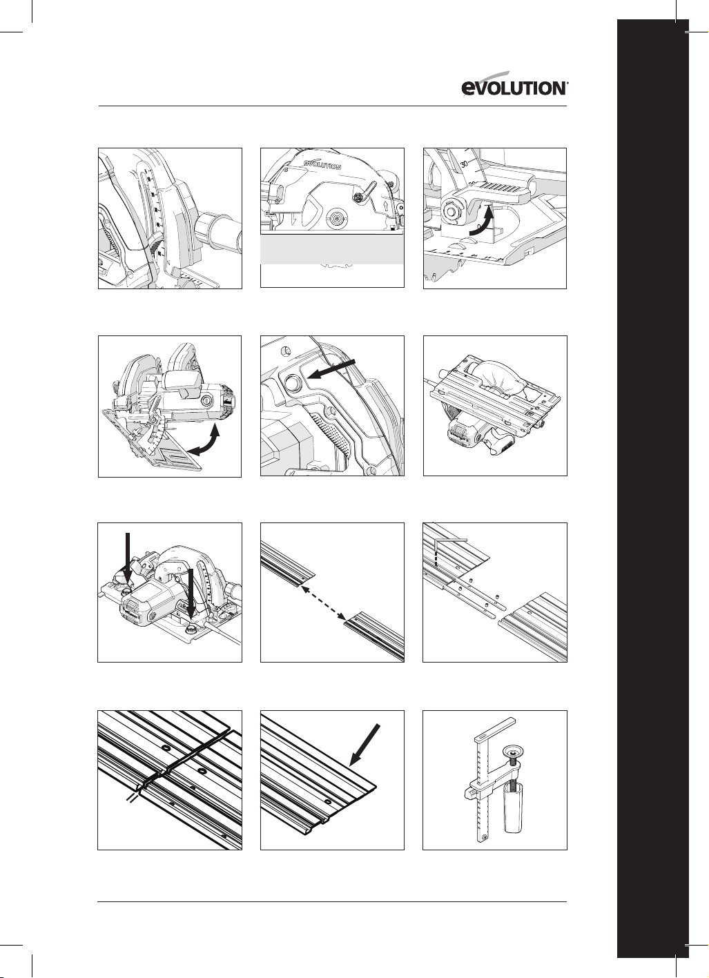
171
www.evolutionpowertools.com
PL
Rys. 11
Rys. 12
Rys. 13
Rys. 14
Rys. 15
Rys. 16
Rys. 17 Rys. 18
Rys. 21Rys. 20
Rys. 19
Rys. 22
1 -2mm

172
www.evolutionpowertools.com
Rys. 25
Port złącza do usuwania pyłu EU
Rys. 27Rys. 26
Rys. 30 Rys. 31
Rys. 34
Rys. 24Rys. 23
Port złącza do usuwania pyłu US
Rys. 28
Rys. 29
Rys. 32 Rys. 33

173
www.evolutionpowertools.com
PL
(10) PRZYGOTOWANIE
OSTRZEŻENIE: Przed zmianą ustawień zawsze należy
odłączyć elektronarzędzie od źródła zasilania.
Uwaga: Urządzenie jest wyposażone w przewód
zasilający i wtyczkę odpowiednie dla danego kraju.
Nie należy zmieniać ani modyfikować przewodu
zasilającego.
(10.1) PROWADNICA RÓWNOLEGŁA
OSTRZEŻENIE: Należy używać jedynie oryginalnych
ostrzy Evolution (lub innych ostrzy zatwierdzonych
przez firmę Evolution Power Tools), przeznaczonych
do stosowania z tym narzędziem. Należy upewnić
się, że maksymalna prędkość tarczy jest zgodna z
tą wskazaną dla urządzenia. Przed rozpoczęciem
montażu należy odłączyć urządzenie od źródła
zasilania.
Uwaga: Zaleca się, aby przed montażem lub wymianą
ostrza operator założył rękawice ochronne.
Należy zlokalizować załączony klucz imbusowy,
który przechowywany jest w schowku na urządzeniu
(znajdującym się w podobnym miejscu we wszystkich
urządzeniach). (Rys. 1)
• Pilarkę należy umieścić na równej, bezpiecznej
powierzchni.
Uwaga: Przy zachowaniu ostrożności wszystkie
urządzenia mogą być oparte na płaskiej, tylnej części
obudowy silnika, (Rys. 2) co daje łatwy dostęp do
ostrza i jego elementów mocujących
• Należy zlokalizować przycisk blokady wrzeciona
(znajdujący się w podobnym miejscu we
wszystkich urządzeniach). Wrzeciono należy
zablokować przy pomocy przycisku blokady.
(Rys. 3).
Uwaga: Powolne wprawienie tarczy w ruch ręką przy
jednoczesnym przyciśnięciu przycisku blokady ułatwi
jego aktywację.
• Przy pomocy klucza imbusowego należy
poluzować i usunąć śrubę, powiązane elementy
mocujące i zewnętrzną podkładkę. (Rys. 4)
Uwaga: Śruba posiada standardowy gwint.
Aby śrubę dokręcić należy przekręcić ją w kierunku
zgodnym z ruchem wskazówek zegara. Aby
śrubę poluzować należy przekręcić ją w kierunku
przeciwnym do ruchu wskazówek zegara.
• Zewnętrzny kołnierz i inne elementy mocujące
należy odłożyć w bezpieczne miejsce.
• Przy pomocy ręcznej dźwigni należy wsunąć dolną
osłonę tarczy w górną osłonę. (Rys. 5)
• Należy ostrożnie zdjąć ostrze z urządzenia (jeśli
jest ono zamocowane).
• Należy dokładnie wyczyścić wewnętrzny i
zewnętrzny kołnierz napędu.
Uwaga: Nie ma konieczności zdejmowania
wewnętrznego kołnierza, ale zaleca się jego
sprawdzenie i wyczyszczenie. Jeśli kołnierz zostanie
zdjęty, zakładając go z powrotem, należy upewnić się,
że jest w takiej samej pozycji jak przed zdjęciem.
• Należy dokładnie wyczyścić tarczę dookoła
otworu (z obu stron), w miejscach gdzie kołnierze
będą stykać się z tarczą i ściskać ją.
• Założyć (nową) tarczę.
• Należy upewnić się, że kierunek strzałek na tarczy
zgadza się z kierunkiem strzałek na górnej i dolnej
osłonie ostrza na urządzeniu. (Rys. 6)
• Należy ponownie zamontować zewnętrzny
kołnierz napędu, śrubę i jej elementy mocujące.
Uwaga: Zewnętrzny kołnierz napędu posiada
specjalnie wycięty otwór z dwoma przeciwległymi
płaskimi brzegami. (Rys. 7a) Brzegi te nakładają się na
odpowiadające płaskie brzegi końcówki trzpienia.
• Należy ponownie uruchomić blokadę trzpienia i
dokręcić śrubę sworznia z łbem gniazdowym przy
użyciu klucza imbusowego.
• Należy zwolnić przycisk blokady trzpienia.
• Klucz imbusowy należy odłożyć na przeznaczone
mu miejsce.
• Należy upewnić się, że przycisk blokady został
całkowicie zwolniony poprzez ręczne wprawienie
tarczy w ruch.
• Należy sprawdzić działanie dolnej osłony ostrza.
Uwaga: W zestawie znajduje się kołnierz z trzpieniem
dwustronnym, umożliwiający ostrza o średnicy 1”
(rys. 7b) i ostrza o średnicy 5/8” (rys. 7c) (Wyłącznie dla
rynku północnoamerykańskiego).
(11)PROWADNICA RÓWNOLEGŁA
Prowadnica Równoległa (Rys. 8), która może być
szczególnie przydatna podczas cięcia wzdłuż,
dołączona jest do wszystkich urządzeń z serii CCS.
Prowadnicę można zamocować z przodu podstawy
urządzenia.
Ramię prowadnicy należy przełożyć przez
prostokątne otwory znajdujące się po obu stronach
(z przodu) tłoczonej, stalowej podstawy, a następnie
przełożyć je pod śrubą regulacyjną znajdującą się po
środku. (Rys. 9)
Uwaga: Prowadnicę można zamocować z obu stron
podstawy urządzenia.
OSTRZEŻENIE: Przed zamocowaniem i ustawieniem
prowadnicy należy odłączyć urządzenie od źródła
zasilania.
Uwaga: Ramię prowadnicy musi zostać przełożone
przez wszystkie prostokątne otwory w podstawie
urządzenia.
OSTRZEŻENIE: Zamontowanie i próba korzystania
z prowadnicy przełożonej jedynie przez jeden (1)
prostokątny otwór w podstawie urządzenia są
potencjalnie niebezpieczne.
Należy ustawić prowadnicę, tak aby była w
odpowiedniej odległości od ostrza, a następnie

174
www.evolutionpowertools.com
dokręcić śrubę regulacyjną.
Należy upewnić się, że prowadnica jest równoległa
do tarczy.
(12) DOSTOSOWANIE GŁEBOKOŚCI CIĘCIA
Uwaga: Wszystkie urządzenia z serii CCS posiadają
te same elementy regulacji głębokości i obsługiwane
są w ten sam prosty sposób w celu ustawienia
głębokości ostrza.
• Należy poluzować mechanizm blokady ustawienia
głębokości poprzez uniesienie dźwigni. (Rys. 10)
(Model CCSL. Inne modele są podobne).
• Należy przestawić podstawę pilarki, aby
wyregulować głębokość cięcia (to jak bardzo
tarcza ma wystawać spod podstawy pilarki).
Uwaga: Miernik głębokości znajduje się w części
ustawienia głębokości, a odpowiadający wskaźnik
został umieszczony na sąsiadującej górnej osłonie
ostrza. (Rys. 11) Korzystanie z tych elementów ułatwi
szybkie ustawienie głębokości.
Uwaga: Korzystanie z miernika głębokości i
wskaźnika pozwala na szybkie ustawienie głębokości,
lecz powinno się traktować je jedynie jako wskazówkę
do uzyskania odpowiedniego ustawienia.
Jeśli konieczne jest bardzo dokładne ustawienie
głębokości, ustawienie ostrza powinno zostać
sprawdzone przy pomocy np. precyzyjnej linijki (nie
załączona w zestawie) i odpowiednio wyregulowane.
W większości przypadków, głębokość cięcia powinna
wynosić tyle, ile grubość obrabianego materiału plus
głębokość połowy zęba tarczy (od czubka zęba do
jego podstawy). (Rys.12)
• Należy zacieśnić mechanizm blokady ustawienia
głębokości przez opuszczenie dźwigni w celu
zablokowania urządzenia w żądanej pozycji.
(13) DOSTOSOWANIE KĄTA CIĘCIA (NACHYLENIA)
Wszystkie maszyny CCSL i CCSX mają możliwość
przechylania ostrza do (maks) 45˚, a wszystkie
maszyny CCS mają możliwość przechylania ostrza do
(maks.) 60˚ w lewo. Umożliwia to wykonywanie cięć
skośnych.
Uwaga: Tarcza znajduje się w pozycji pionowej, kiedy
podziałka kątomierza wskazuje 0°.
Uwaga: Podziałka kątomierza (0°- 45°) znajduje
się w części blokady skosu z przodu podstawy
pilarki. Korzystanie z kątomierza pozwoli na szybkie
ustawienie kąta skosu, lecz powinno się traktować go
jedynie jako wskazówkę.
Jeśli konieczne jest bardzo dokładne ustawienie kąta
skosu, ustawienie ostrza powinno zostać sprawdzone
przy pomocy miernika nachylenia (nie załączony w
zestawie) i odpowiednio wyregulowane.
• Należy poluzować mechanizm blokady ukosu
znajdujący się z przodu urządzenia poprzez
uniesienie dźwigni. (Rys. 13)
• Należy przechylić tarczę do żądanego kąta
zgodnie z podziałką kątomierza. (Rys. 14)
• Gdy żądany kąt zostanie osiągnięty, należy
zacieśnić mechanizm blokady skosu poprzez
opuszczenie dźwigni.
(14) ZALECENIA DOT. OBSŁUGI
(CZYNNOŚCI KONTROLNE)
Uwaga: Środowiska pracy różnią się od siebie. Firma
Evolution Power Tools oferuje operatorom poniższe,
ogólne zalecenia dotyczące bezpiecznej obsługi.
Lista zaleceń nie jest wyczerpująca, gdyż firma
Evolution nie ma wpływu na rodzaj warsztatu i
środowiska pracy, w którym urządzenie będzie
używane.
Zalecamy, aby operator zasięgnął porady od
właściwego organu lub kierownika warsztatu w
razie wątpliwości dotyczących dowolnego aspektu
korzystania z tego urządzenia.
Ważne jest, aby przed każdym użyciem operator
przeprowadził rutynowe czynności kontrolne.
OSTRZEŻENIE: Podczas przeprowadzania tych
czynności urządzenie powinno być odłączone od
zasilania.
• Należy upewnić się, że osłony bezpieczeństwa
działają prawidłowo oraz że wszystkie uchwyty i
śruby regulacyjne są dokręcone.
• Należy sprawdzić, czy tarcza jest zamontowana
bezpiecznie i prawidłowo. Należy również
upewnić się, czy tarcza jest odpowiednia do cięcia
wybranego materiału.
• Należy sprawdzić, czy przewód zasilania jest
nienaruszony.
• W miarę możliwości należy przymocować
przedmiot obróbki za pomocą zacisku do ławy
warsztatowej lub kozła, itp.
• Operator powinien zawsze kontrolować pozycję i
ułożenie przewodu zasilania.
(15) ŚRODKI OCHRONY OSOBISTEJ
• Operator powinien stosować środki ochrony
osobistej odpowiednie do wykonywanego
zadania. Mogą to być m.in. okulary ochronne,
osłona twarzy, maska przeciwpyłowa, obuwie
robocze, itd.
Uwaga: Wszystkie urządzenia z serii CCS wyposażone
są w dmuchawę usuwającą trociny z linii cięcia.
Przekierowuje ona powietrze z wentylatora
napędzanego silnikiem do przestrzeni z przodu
tarczy, pozostawiając linię cięcia względnie czystą.
Funkcja ta poprawia widoczność i pozwala
operatorowi śledzić ruch ostrza podczas cięcia wzdłuż
linii pomocniczych.
OSTRZEŻENIE: Pył powstający podczas cięcia jest
potencjalnie szkodliwy dla zdrowia.
Niektóre materiały mogą być szczególnie
szkodliwe. Operator powinien zawsze nosić maskę

175
www.evolutionpowertools.com
PL
przeciwpyłową odpowiednią do rodzaju obrabianego
materiału.
W razie wątpliwości dotyczących potencjalnej
toksyczności obrabianego materiału operator
powinien zasięgnąć porady i pomocy profesjonalisty.
OSTRZEŻENIE: Pod żadnym pozorem nie należy
używać urządzenia do cięcia azbestu oraz materiałów,
które go zawierają lub mogą go zawierać.
W razie podejrzenia o skażeniu azbestem należy
powiadomić odpowiedni organ i zasięgnąć
dodatkowej porady.
(16) PRZEŁĄCZNIK ON/OFF
Uwaga: Wszystkie urządzenia przeznaczone na
rynek europejski i australijski wyposażone są w
przełącznik „bezpiecznego startu” w celu zwiększenia
bezpieczeństwa operatora. (Rys.15)
Aby uruchomić silnik, należy:
• wcisnąć kciukiem przycisk blokady
bezpieczeństwa znajdujący się z boku uchwytu.
• wcisnąć przełącznik.
Aby zatrzymać silnik, należy:
• zwolnić przełącznik.
OSTRZEŻENIE: Nigdy nie należy uruchamiać silnika,
gdy ostrze dotyka bezpośrednio do przedmiotu
obróbki.
Uwaga: Urządzenia przeznaczone na rynek
północnoamerykański wyposażone są w przełącznik
ON/OFF, który nie zawiera przełącznika „bezpiecznego
startu”.
OSTRZEŻENIE: Jeśli piła jest pod napięciem (dioda
LED jest włączona), należy unikać nieumyślnego
uruchomienia silnika podczas podnoszenia
urządzenia ze stołu warsztatowego itp. Przypadkowe
zwolnienie przełącznika ON/OFF (umieszczonego na
uchwycie głównym) podczas podnoszenia maszyny z
pozycji leżącej spowoduje uruchomienie silnika.
PROWADNICE DO CIĘCIA
Urządzenia z serii CCSX firmy Evolution (dotyczy
modeli wymienionych na stronie specyfikacji)
zostały zaprojektowane i wyposażone w
taki sposób, aby były one kompatybilne z
prowadnicami do cięcia.
Uwaga: Każda pilarka posiadająca kanały wzdłuż
podstawy może być używana z wykorzystaniem
prowadnic do cięcia (Rys. 16)
Urządzenia firmy Evolution wyposażone w takie
kanały, mogą być używane z większością prowadnic
do cięcia obecnie dostępnymi na rynku.
Uwaga: Należy zapoznać się z dokumentacją
dostarczoną przez producenta prowadnic.
Dokumentacja ta zazwyczaj zawiera instrukcje
montażu prowadnicy, jak również informacje
dotyczące bezpiecznych sposobów wykonywania
pracy, które muszą być stosowane podczas pracy z
tego typu urządzeniami.
Prowadnice do cięcia mogą być stosowane, jeśli:
• użycie przecinarki lub pilarki mogłoby stwarzać
zagrożenie dla zdrowia lub bezpieczeństwa (BHP)
bądź inne problemy w miejscu pracy. Na przykład
podczas pracy na placu budowy, gdzie niezbędna
jest wyjątkowa dokładność i kontrola (praca na
dachu lub platformie rusztowania itd.), użycie
prowadnicy do cięcia może zapewnić operatorowi
dodatkowe (i bezpieczne) możliwości robocze.
• wymagane są dokładne cięcia w poprzek lub
wzdłuż dużych obrabianych przedmiotów. Na
przykład podczas obróbki ram, drzwi, dużych płyt
lub paneli ściennych, itp. prowadnica do cięcia
mogłaby wyeliminować potrzebę użycia pilarki w
trybie „ręcznym”.
Uwaga: Kompatybilne z prowadnicami do cięcia
urządzenia firmy Evolution wyposażone są w dwie (2)
krzywki znajdujące się w kanale podstawy (po obu
stronach). „Przyciski rotacyjne” (Rys. 17) umożliwiają
operatorowi obracanie krzywek.
Regulacja krzywek nieznacznie zmniejszy efektywną
szerokość kanału podstawy. Może to być konieczne
w celu dopasowania do jakiejkolwiek nieznacznej
zmiany szerokości szyny, która może wystąpić
podczas wytłoczenia prowadnic. Rozstaw szyn
produkowanych przez różnych producentów
prowadnic może się nieznacznie różnić.
Uwaga: Operator powinien tak ustawić krzywki,
aby po prawidłowym umieszczeniu maszyny na
prowadnicy można ją było łatwo i płynnie przesuwać
do przodu lub do tyłu, bez widocznego ruchu
bocznego (chybotania).
PROWADNICE DO CIĘCIA EVOLUTION
Niektóre urządzenia firmy Evolution (w zależności od
modelu i rynku przeznaczenia) są dostarczane wraz z
prowadnicami do cięcia.
Uwaga: Prowadnice do cięcia Evolution są dostępne
na zasadzie opcji zakupu przez klientów. Prosimy o
kontakt z lokalnym dystrybutorem firmy Evolution
Power Tools w celu uzyskania dalszych szczegółów.
PROWADNICA
System prowadnic firmy Evolution składa się z
dwóch (2) lub trzech (3) odcinków szyn precyzyjnie
wytłoczonych ze stopu. (Rys. 18) Odcinki te muszą
być połączone ze sobą za pomocą dołączonych
prętów łączących. (Rys. 19)
Aby połączyć odcinki szyn należy (Rys. 19):
• Wsunąć pręty w szczeliny „T” znajdującej się pod

176
www.evolutionpowertools.com
powierzchnią wytoczonych szyn.
• Upewnić się, że pręty zostały włożone w
obydwa łączone odcinki na równej długości (w
przybliżeniu).
• Dokręcić śruby z łbem gniazdowym w celu
dokładnego połączenia odcinków.
Uwaga: Należy pamiętać o zachowaniu niewielkiej
luki pomiędzy połączonymi odcinkami (między 1 a 2
mm). Dzięki temu po zamontowaniu pilarki tarczowej
i użyciu jej wraz z prowadnicą cięcia krzyżowego
Evolution, będzie się ona przesuwać się płynnie
wzdłuż całej długości prowadnicy.
USTAWIANIE PIŁY NA PROWADNICY
Uwaga: Poniższe wskazówki odnoszą się do pilarek
i prowadnic do cięcia EVOLUTION. Należy zapoznać
się z informacjami dostarczonymi przez producentów
pił i/lub prowadnic do cięcia, jeśli będą Państwo
korzystać z piły tarczowej lub prowadnicy do cięcia
firm innych niż Evolution.
Przed pierwszym użyciem prowadnicy do cięcia
EVOLUTION należy sprawdzić, czy pasek chroniący
przed odłamkami (Rys. 21) pasuje do piły i ostrza.
Aby dopasować piłę do prowadnicy należy:
• W pełni złożyć prowadnicę do cięcia.
• Dokładnie zapoznać się z rozdziałem
„Umiejscowienie i mocowanie prowadnicy”.
Zamocować prowadnicę na płycie z
odpowiedniego materiału zapasowego lub
materiału z odpadów.
• Ustawić ostrze piły na odpowiedniej głębokości
wybranego do cięcia materiału.
• Upewnić się, że nie ma żadnych przeszkód pod
ścieżką ostrza.
• Dokładnie zapoznać się z rozdziałem
„Umiejscowienie i mocowanie prowadnicy”.
Umieścić poprawnie piłę tarczową na prowadnicy.
• Włączyć silnik i zaczekać, aż ostrze osiągnie
prędkość maksymalną.
• Popychać piłę tarczową wzdłuż całej długości
prowadnicy płynnym i powolnym ruchem do
momentu, w którym ostrze przetnie całą długość
paska chroniącego przed odłamkami.
Uwaga: Ten proces dopasuje konkretne ostrze do
konkretnej prowadnicy.
Se for utilizada uma serra diferente numa pista
preparada deste modo, a fita antiestilhaços pode
não fornecer o mesmo nível de proteção como na
configuração específica da serra à pista.
Uwaga: Taśma zabezpieczenia
przeciwodpryskowego jest produktem, który się
zużywa. Z biegiem czasu ulegnie zużyciu i sparcieje
oraz będzie wymagać wymiany. Zaleca się również
jej wymianę w przypadku użycia innej pilarki lub
ostrza (np. o innej szerokości cięcia), niż oryginalnie
dopasowanych do uszczelki.
WYMIENNY PASEK CHRONIĄCY PRZED
ODŁAMKAMI
Jako element podlegający zużyciu pasek chroniący
przed odłamkami powinien być sprawdzany w
regularnych odstępach czasu pod kątem uszkodzeń
lub otarć spowodowanych „zużyciem”. Pasek należy
wymienić, jeśli widoczne są jakiekolwiek uszkodzenia
lub znaczące zużycie.
Dostępne są paski zamienne. Należy skonsultować
się ze swoim dostawcą lub firmą Evolution za
pośrednictwem odpowiedniej infolinii.
Załączony wymienny pasek chroniący przed
odłamkami jest bezpośrednim zamiennikiem paska
oryginalnego. Aby wymienić pasek należy ostrożnie
zdjąć zużyty pasek z prowadnicy i zastąpić go nowym.
Uwaga: Po wymianie paska należy ponownie
przeprowadzić procedurę dopasowania piły do
prowadnicy.
ZACISKI DO PROWADNIC EVOLUTION
(DO NABYCIA ODDZIELNIE)
Szybki zacisk EVOLUTION (Rys. 22) został
zaprojektowany specjalnie do mocowania prowadnic
do cięcia EVOLUTION.
Uwaga: Dodatkowe zaciski można kupić od firmy
Evolution Power Tools lub od lokalnego dystrybutora.
Zaciski Evolution pasują do szczelin „T”. które
znajdują się pod powierzchnią szyn wytłoczonych ze
stopu oraz mogą się wzdłuż nich przesuwać. (Rys.
23)
Umożliwia to operatorowi umieszczenie zacisków
(jeden jest wymagany na każdym końcu prowadnicy)
w pozycjach, które zapewniają maksymalne
bezpieczeństwo i unieruchomienie prowadnicy do
cięcia względem obrabianego przedmioty.
USTAWIENIE I MOCOWANIE PROWADNICY
Uwaga: Poniższe wskazówki służą jedynie jako
porady. Firma Evolution nie ma wpływu na
środowisko pracy ani warunki, w których ten sprzęt
jest używany.
OSTRZEŻENIE: Jeśli sprzęt ma być używany na
placu budowy, operator powinien skonsultować się
z odpowiednią osobą, która jest odpowiedzialna za
bezpieczeństwo i higienę pracy, w celu uzyskania
dalszych szczegółowych informacji dotyczących
bezpieczeństwa w miejscu pracy.
• Należy wyraźnie oznaczyć element obrabiany, a
zwłaszcza „linię cięcia”, wzdłuż której ostrze będzie
się poruszać.
• Należy zmontować prowadnicę do cięcia z tylu
odcinków, ile potrzeba, aby wystarczyła dla
elementu obrabianego, plus konieczny naddatek
na wysięg.
• Ustawić prowadnicę na obrabianym przedmiocie

177
www.evolutionpowertools.com
PL
i zabezpieczyć ją, za pomocą zacisków Evolution
(preferowane) lub odpowiednich zacisków typu
„ G ”.
• Należy upewnić się, że krawędź paska chroniącego
przed odłamkami przebiega dokładnie wzdłuż
wytyczonej linii cięcia.
OSTRZEŻENIE: Prowadnica do cięcia musi
wystawać poza przedmiot obrabiany przy krawędzi
prowadzącej. (Rys. 24)
Dolna osłona ostrza będzie musiała zostać ręcznie
wycofana i skierowana do góry na górną osłonę
tarczy, gdy pilarka zostanie umieszczona na
prowadnicy.
OSTRZEŻENIE: W tej pozycji ostrze będzie
odsłonięte. NIE WOLNO uruchamiać piły zanim
nie zostaną podjęte wszystkie środki kontroli
bezpieczeństwa.
WYKONYWANIE CIĘCIA
Wykonywanie cięcia przy pomocy prowadnicy do
cięcia jest bardzo podobne do cięcia zwykłą pilarką.
Wszystkie procedury bezpieczeństwa, które dotyczą
pracy z pilarką mają również zastosowanie w pracy z
piłą w połączeniu z prowadnicą do cięcia.
Poniższe wskazówki, choć nie są wyczerpujące,
zawierają ogólne zalecenia:
• Należy przeprowadzić kontrolę bezpieczeństwa,
aby upewnić się, że prowadnica do cięcia
jest dobrze przymocowana do obrabianego
przedmiotu, a sam przedmiot jest również
zabezpieczony i nie będzie się poruszał podczas
cięcia.
• Należy sprawdzić, czy pod obrabianym
przedmiotem nie ma przeszkód, które mogłyby
zahamować lub przeszkodzić w cięciu lub które
mogłyby doprowadzić do uszkodzenia przedmiotu
obrabianego przez ostrze.
• Należy upewnić się, że kabel zasilający
jest poprowadzony w taki sposób, że nie
stwarza zagrożenia potknięciem lub innego
niebezpieczeństwa. Należy zwrócić szczególną
uwagę, żeby kabel zasilający nie mógł się zetknąć
z obracającym się ostrzem piły.
• Operator powinien dopilnować, aby podczas
przesuwania piły wzdłuż prowadnicy zachować
pewną postawę na nogach, dobrą równowagę
i całkowitą kontrolę przez cały czas cięcia.
Szczególną ostrożność należy zachować w
momencie, kiedy ostrze jest wyjmowane z
obrabianego przedmiotu.
OSTRZEŻENIE: Należy się upewnić, że obrabiany
przedmiot nie spadnie ze stołu i nie spowoduje
uszczerbku na zdrowiu u osób postronnych, w
szczególności podczas pracy na wysokości (a także
innych warunkach, które mogą mieć zastosowanie).
Operator powinien być przygotowany na ewentualne
zabezpieczenie lub przechwycenie odciętego
przedmiotu. Należy skonsultować się w tej sprawie
z osobą odpowiedzialną za BHP w celu uzyskania
szczegółowych wskazówek.
Uwaga: Zaleca się, aby przed pierwszym użyciem
operator przeprowadził próbę cięcia na urządzeniu
niepodłączonym do sieci w celu upewnienia się, że
cała procedura będzie w pełni bezpieczna.
Po zakończonym cięciu należy wyłączyć urządzenie
przełącznikiem ON/OFF i zaczekać, aż ostrze
całkowicie się zatrzyma.
Po podniesieniu piły znad prowadnicy do cięcia
i przedmiotu obrabianego, dolna osłona ostrza
automatycznie w całości zakryje ostrze.
USUWANIE PYŁU I INNYCH POZOSTAŁOŚCI PO
CIĘCIU
Łączniki (Rys. 25) mogą być montowane we
wszystkich urządzeniach CCS. Łącznik taki umożliwia
podłączenie do urządzenia zbierającego pył po cięciu.
Uwaga: Dokładny kształt łącznika będzie się różnił w
zależności od typu modelu lub rynku przeznaczenia
urządzenia. Dostarczony łącznik będzie pasował do
wielu urządzeń usuwających pył, jakie są dostępne
na rynku. Łącznik należy przymocować do gniazda
wylotowego ciętego materiału (Rys. 26)
Uwaga: W razie potrzeby do łącznika do usuwania
pyłu można podłączyć warsztatowe urządzenie do
odsysania pyłów. Należy postępować zgodnie z
instrukcjami producenta odnośnie podłączenia oraz
sprawdzić, czy urządzenie czyszczące ma możliwość
przyjęcia pozostałości materiału po cięciu.
OŚWIETLENIE LED
Niektóre urządzenia (w zależności od modelu i rynku
przeznaczenia) są dostarczane wraz z automatyczną
diodą LED.
Uwaga: Jeśli nie ma pewności, które funkcje są
dostępne w danym urządzeniu, należy zapoznać
się ze specyfikacją urządzenia podaną w niniejszej
instrukcji. Dioda LED znajduje się po lewej stronie
(LH) ostrza.
Wiązka z diody LED zaświeci się po lewej stronie
ostrza oraz oświetli wszystkie linie oznaczenia
narysowane na obrabianym przedmiocie. Dzięki
temu operator będzie miał lepszy wgląd w ścieżkę
ostrza poruszającego się na obrabianym przedmiocie,
co zapewni lepszą efektywność, dokładność i
bezpieczeństwo.
Uwaga: Dioda LED włącza się automatycznie.
Dioda LED jest włączana w momencie podłączenia
urządzenia do prądu. W ten sposób operator będzie
wyraźnie widział, że urządzenie zostało prawidłowo
podłączone do zasilania, posiada dopływ prądu (jest
pod napięciem) i jest gotowe do pracy.
Uwaga: W zestawie montażowym nie ma części

178
www.evolutionpowertools.com
związanych z montażem diody LED, które mogą
być obsługiwane przez użytkownika, a wiązka
padania światła została ustawiona fabrycznie. Osłona
zabezpieczająca diody powinna być trzymana z
daleka od kurzu (patrz część poświęcona konserwacji
urządzenia) w celu zapewnienia maksymalnej
jasności wiązki światła.
OSTRZEŻENIE: Osłonę diody należy czyścić, kiedy
urządzenie jest odłączone od prądu, a ostrze znajduje
się w całkowitym bezruchu.
ELEMENTY WSPOMAGAJĄCE CIĘCIE
Piły tarczowe Evolution są wyposażone w różne
elementy stworzone z myślą o ułatwieniu pracy
operatorowi tak, aby cięcie było szybkie, dokładne i
bezpieczne. Uwaga: Nie wszystkie poniższe elementy
znajdują się na każdym urządzeniu.
Prowadnik linii cięcia pod kątami 0˚ i 45˚ (Rys. 28)
Na przedniej krawędzi urządzenia przy podstawie
znajdują się dwa (2) małe nacięcia, które są oznaczone
na niektórych urządzeniach za pomocą liczb
kątowych. Nacięcia te wskazują nastawienie ostrza w
momencie wbijania się w obrabiany przedmiot, kiedy
nachylenie kątownika jest ustawione pod kątem 0˚
(ostrze w pozycji pionowej) lub pod kątem 45˚.
Prowadnica przedniej części ostrza (Rys. 29)
Uwaga: Urządzenia firmy EVOLUTION kompatybilne
z prowadnicą do cięcia EVOLUTION posiadają nacięcie
na podstawie po prawej stronie (RH). Nacięcie to
wskazuje pozycję przedniej krawędzi ostrza, kiedy
ostrze jest ustawione na maksymalną głębokość
cięcia. Ta funkcja może być wykorzystywana podczas
umieszczania i ustawiania piły na prowadnicy do
cięcia.
OSTRZEŻENIE: Należy uważać, aby dolna osłona
ostrza lub samo ostrze nie dotykało żadnego
elementu obrabianego przedmiotu podczas
wstępnego ustawiania piły na prowadnicy do cięcia.
Prowadnice z linijką (Rys. 30)
Prowadnice z linijką znajdują się na niektórych
pilarkach Evolution. Znajdują się one wzdłuż
przedniej i/lub bocznej krawędzi podstawy. Te
prowadnice mogą określić przybliżoną pozycję lub
umożliwią lepszy ogląd pracy ostrza na obrabianym
przedmiocie.
REGULACJA SPECJALISTYCZNA
Urządzenia firmy Evolution posiadają wiele
precyzyjnie zaprojektowanych elementów i ustawień,
z których większość jest ustawiona fabrycznie w
taki sposób, aby zapewnić długotrwałe poprawne
działanie urządzenia.
Serwis i regulacja tych komponentów lub ustawień
prawdopodobnie nigdy nie będą konieczne. Jeśli
serwis lub regulacja (po odpowiednio długim
użytkowaniu) okaże się konieczna, firma Evolution
zaleca kontakt z pomocą techniczną w celu uzyskania
dalszych wskazówek.
Uwaga: Niektóre procedury regulacji mogą być
wykonywane wyłącznie przez osoby posiadające
specjalistyczną wiedzę i/lub dysponujące
odpowiednim sprzętem.
(17) ZALECENIA DOT. CIĘCIA
OSTRZEŻENIE: Operator musi zawsze kontrolować
pozycję i ułożenie przewodu zasilania. Przewód
należy umiejscowić w takim położeniu, by nie miało
możliwości zetknięcia z ostrzem.
Przewód nie powinien stwarzać żadnego zagrożenia
(np. potknięcia) dla operatora i /lub obserwatorów.
• Nie należy przeciążać urządzenia.
• Należy pozwolić, aby prędkość tarczy
narzucała siłę cięcia. Nadmierne napieranie na
urządzenie w żaden sposób nie polepszy jego
działania, a jedynie skróci żywotność tarczy.
• Korzystając z prowadnicy należy upewnić się, że
jest ona ustawiona równolegle do tarczy.
Jeśli prowadnica ustawiona jest nieprawidłowo
może dojść do uszkodzenia tarczy i/lub silnika.
• Przednią krawędź podstawy pilarki należy
postawić na obrabianym przedmiocie. Przed
włączeniem silnika należy upewnić się, że ostrze
nie styka się z przedmiotem obróbki.
• Rozpoczynając cięcie należy powoli
wprowadzić ostrze w materiał, aby nie naruszyć
zębów tarczy
Uwaga: Z przodu podstawy urządzenia CCSL
znajdują się dwie (2) linie prowadzące (przeznaczone
jedynie do cięcia po kątem 0° i 45°).
• Pilarkę należy przesuwać oburącz do przodu tnąc
przez obrabiany materiał.
• Przesuwając pilarkę do przodu przez obrabiany
materiał, należy wywierać na nią stały,
równomierny napór.
Uwaga: All CCS series machines have an automatic
lower blade guard which has a specially shaped
leading front edge. This feature ensures that the
blade guard retracts smoothly and eortlessly as
the machines blade enters the workpiece. As the
blade exits the workpiece the lower blade guard will
automatically return to its normal position covering
the blade completely.
Uwaga: W niektórych przypadkach, np. podczas
wykonywania cięcia wgłębnego w podłogę lub ścianę
itp., przydatne może okazać się ręczne cofnięcie
dolnej osłony ostrza.
Na dolnej osłonie ostrza znajduje się dźwignia
operowana kciukiem. Zachowując ostrożność,
doświadczony operator może ręcznie wycofać osłonę
(całkowicie lub częściowo) w celu wykonania cięcia
wgłębnego.

179
www.evolutionpowertools.com
PL
OSTRZEŻENIE: Osłonę tarczy należy wycofywać
ręcznie ze szczególną uwagą, upewniając się, że
ręka ani palce operatora nie dotykają żadnego
elementu ostrza.
Po zakończeniu cięcia należy:
• Zwolnić przełącznik ON/OFF.
• Zaczekać, aż tarcza całkowicie się zatrzyma.
• Wycofać urządzenie z przedmiotu obróbki,
pozwalając dolnej osłonie automatyczne
powrócić na swoje miejsce i zakryć ostrze.
OSTRZEŻENIE: W przypadku zatrzymania lub
zgaśnięcia silnika podczas wykonywania cięcia
należy od razu zwolnić przełącznik. Należy odłączyć
urządzenie od źródła zasilania i wysunąć je z
obrabianego przedmiotu. Należy zidentykować
źródło problemu i jeśli to możliwe, dokonać naprawy.
Silnik może zostać ponownie włączony jedynie wtedy,
gdy operator ma pewność, że jest to bezpieczne.
WYRZUTNIK TROCIN
OSTRZEŻENIE: Nie stosować odpylacza workowego
ani adaptera odpylacza podczas cięcia materiałów
metalowych, w tym drewna zawierającego gwoździe.
(18) KONSERWACJA I REGULACJA
Pionowa pozycja ostrza (0°) może zostać zmieniona.
OSTRZEŻENIE: Przed rozpoczęciem tej procedury
należy odłączyć urządzenie od źródła zasilania.
Aby sprawdzić pozycję 0°, należy:
• Ustawić tarczę w pozycji 0° przy pomocy
mechanizmu przechyłu aż do zatrzymania.
• Sprawdzić pozycję tarczy względem podstawy
pilarki przy pomocy kątownika (nie załączony).
Należy unikać kontaktu z końcówkami zębów
ostrza z węglika wolframu TCT. Tarcza powinna być
ustawiona dokładnie pod kątem 90° do podstawy
pilarki.
Uwaga: Dolna osłona ostrza powinna zostać (ręcznie)
cofnięta do wewnątrz górnej osłony. Pozwoli to na
dokładne przystawienie kątownika i ułatwi proces
kontrolny.
Jeśli konieczna jest regulacja:
R165CCSL & 185CCS
Należy przekręcić śrubę regulacyjną (rys. 31)
w odpowiednim kierunku przy pomocy klucza
imbusowego 4 mm (nie załączony) tak, aby tarcza
znajdowała się dokładnie pod kątem 90° do podstawy
pilarki.
R185CCSX & 185CCSX+
Należy przekręcić śrubę regulacyjną (rys. 32)
w odpowiednim kierunku przy pomocy klucza
imbusowego 3 mm (nie załączony), tak aby tarcza
znajdowała się dokładnie pod kątem 90° do podstawy
pilarki.
Aby sprawdzić pozycję 45˚ (R185CCSX i 185CCSX
+):
• Ustawić tarczę w pozycji 45° przy pomocy
mechanizmu przechyłu aż do zatrzymania.
• Sprawdzić pozycję tarczy względem podstawy
pilarki przy pomocy kątownika (nie załączony).
Należy unikać kontaktu z końcówkami zębów
ostrza z węglika wolframu TCT. Tarcza powinna być
ustawiona dokładnie pod kątem 45° do podstawy
pilarki.
Należy przekręcić śrubę regulacyjną (rys. 33)
w odpowiednim kierunku przy pomocy klucza
imbusowego 3 mm (nie załączony) tak, aby tarcza
znajdowała się dokładnie pod kątem 45° do podstawy
pilarki.
(19) KONTROLA I WYMIANA
SZCZOTEK WĘGLOWYCH
OSTRZEŻENIE: Przed przystąpieniem do kontroli
lub wymiany szczotek węglowych należy odłączyć
urządzenie od źródła zasilania.
Uwaga: Należy wymienić obie szczotki węglowe, w
przypadku, gdy którakolwiek z nich ma mniej niż 6
mm długości pozostałego węgla lub jeśli sprężyna
albo przewód są uszkodzone bądź przepalone.
Aby usunąć szczotki, należy:
• Odkręcić plastikowe nakrętki znajdujące się w
tylnej części obudowy silnika. (Rys. 17) Należy
uważać, gdyż nakrętki posiadają sprężyny.
• Usunąć szczotki wraz z ich sprężynami.
• Jeżeli wymiana jest konieczna, należy wstawić
nowe szczotki i nałożyć nakrętki.
Uwaga: Używane, ale sprawne szczotki mogą być
zostać ponownie założone pod warunkiem, że
ustawione zostaną ponownie w tej samej pozycji
i zostaną włożone w ten sam sposób, w jaki zostały
wyjęte z urządzenia.
• Należy uruchomić silnik bez obciążenia na około
5 minut. Pozwoli to na osadzenie się nowych
szczotek i sprawdzenie, czy silnik działa sprawnie.
• Do momentu całkowitego osadzenia się szczotek
możliwe jest wystąpienie iskier.
(20) KONSERWACJA I CZYSZCZENIE
Uwaga: Przed przystąpieniem do czynności
konserwacyjnych należy upewnić się, że urządzenie
jest wyłączone i odłączone od źródła zasilania.
• Należy regularnie sprawdzać, czy wszystkie
elementy zabezpieczające i osłony działają
poprawnie. Urządzenia można używać jedynie
wtedy, gdy wszystkie elementy ochronne i osłony
są w pełni funkcjonalne.
• Wszystkie łożyska silnika w tym urządzeniu
posiadają dożywotni zapas smaru. Dodatkowe
smarowanie nie jest wymagane.
Plastikowe części maszyny należy czyścić czystą,
lekko zwilżoną szmatką. Nie należy używać

180
www.evolutionpowertools.com
rozpuszczalników lub podobnych produktów, które
mogłyby uszkodzić plastikowe części.
Należy usuwać kurz i inne zabrudzenia z nasadki
soczewki modułu LED.
OSTRZEŻENIE: Nie wolno podejmować prób
czyszczenia narzędzia poprzez wkładanie spiczastych
przedmiotów w otwory w obudowie urządzenia,
itp. Otwory wentylacyjne maszyny należy czyścić za
pomocą sprężonego powietrza.
Uwaga: Podczas korzystania ze sprężonego
powietrza w celach czyszczenia operator powinien
stosować środki ochrony osobistej.
(21) ZUŻYTY SPRZĘT ELEKTRYCZNY
IELEKTRONICZNY
Ten symbol jest znany jako „symbol
przekreślonego pojemnika na odpady na
kółkach”. Jeśli ten symbol jest umieszczony
na produkcie lub baterii, oznacza to, że
nie należy ich wyrzucać wraz ze zwykłymi
odpadami komunalnymi. Niektóre
chemikalia znajdujące się w produktach
elektrycznych i elektronicznych lub
bateriach oraz akumulatorach mogą być
szkodliwe dla zdrowia i środowiska.
Odpady produktów elektronicznych nie powinny
zostać zutylizowane wraz z odpadami gospodarstwa
domowego. Jeżeli to możliwe, poddać utylizacji.
Zużyty sprzęt elektryczny i elektroniczny zawiera
substancje nieobojętne dla środowiska naturalnego.
Sprzęt nie poddany recyclingowi stanowi potencjalne
zagrożenie dla środowiska i zdrowia ludzi.
Należy oddać go do sklepów Castoramy w
wyznaczonych miejscach. Wskazówki dotyczące
recyclingu można uzyskać od sprzedawcy lub
sprawdzając lokalne przepisy.
181
www.evolutionpowertools.com
PL
DEKLARACJA ZGODNOŚCI WE
Producent artykułu objętego niniejszą deklaracją to:
UK: Evolution Power Tools Ltd, Venture One, Longacre Close, Holbrook Industrial Estate, Sheeld, S20 3FR.
FR: Evolution Power Tools SAS, 61 Avenue Lafontaine, 33560, Carbon-Blanc, Bordeaux, France.
Producent deklaruje niniejszym, że urządzenie, jak opisano w niniejszej deklaracji, spełnia wszystkie
odpowiednie przepisy dyrektywy maszynowej i innych odpowiednich dyrektyw wymienionych poniżej.
Producent oświadcza, że urządzenie, jak opisano w niniejszym oświadczeniu, w stosownych przypadkach
spełnia odpowiednie przepisy w zakresie ochrony zdrowia i bezpieczeństwa.
The Directives covered by this Declaration are as detailed below:
I jest zgodne z obowiązującymi wymaganiami określonymi w następujących dokumentach:
EN IEC 55014-1:2021 • EN IEC 55014-2:2021 • EN IEC 61000-3-2:2019/A1:2021 •
EN 62841-1:2015/A11:2022 • EN62841-2-5:2014 • EN 55014-1:2017+A11:2020 • EN 55014-2:2015
EN 61000-3-2: 2014 (220-240V)• EN IEC 61000-3-2:2019 (220-240V) •
EN 61000-3-3:2013+A1:2019 (026-0001) • EN IEC 61000-3-11:2019 (220-240V z wyjątkiem
modelu 026-0001)
Dane Produktu
Opis: R165CCSL 165mm (6-1/2”) Circular Saw
Nr modelu Evolution: 026-0001 / 026-0002 / 026-0003
Opis: R185CCS 185mm (7-1/4”) Circular Saw
Nr modelu Evolution: 027-0001C / 027-0002C / 027-0003C
Opis: R185CCSX 185mm (7-1/4”) Circular Saw
Nr modelu Evolution: 027-0001 / 027-0002 / 027-0003
Opis: R185CCSX+ 185mm (7-1/4”) Circular Saw
Nr modelu Evolution: 027-0001A / 027-0002A / 027-0003A
Nazwa marki: EVOLUTION POWER TOOLS LIMITED
Napięcie: 220-240V / 110V ~ 50Hz
Moc wejściowa: R165CCSL - 1200W
R185CCS, R185CCSX & R185CCSX+ - 1600W
Dokumentacja techniczna, wykazująca że produkt spełnia wymagania dyrektywy, została opracowana
i jest dostępna do wglądu dla właściwych organów egzekwowania prawa oraz potwierdza, iż nasza
dokumentacja techniczna zawiera dokumenty wymienione powyżej
i że są to właściwe normy dla produktu zgodnie z powyższymi informacjami.
Imię, nazwisko i adres posiadacza dokumentacji technicznej.
Podpisano: Druk: Barry Bloomer
Kierownik Działu Zamówień i Zaopatrzenia
Data: 21/02/23
UK: Evolution Power Tools Ltd, Venture One, Longacre Close, Holbrook Industrial Estate, Sheeld, S20 3FR.
FR: Evolution Power Tools SAS, 61 Avenue Lafontaine, 33560, Carbon-Blanc, Bordeaux, France.
2006/42/CE. Dyrektywa Maszynowa.
2014/30/UE. Dyrektywa kompatybilności elektromagnetycznej.
2011/65/EU. &
2015/863/EU.
Dyrektywa w sprawie ograniczenia stosowania niektórych niebezpiecznych substancji w sprzęcie
elektrycznym i elektronicznym (dyrektywa RoHS).
2012/19/UE. Dyrektywa w sprawie zużytego sprzętu elektrycznego i elektronicznego (WEEE).
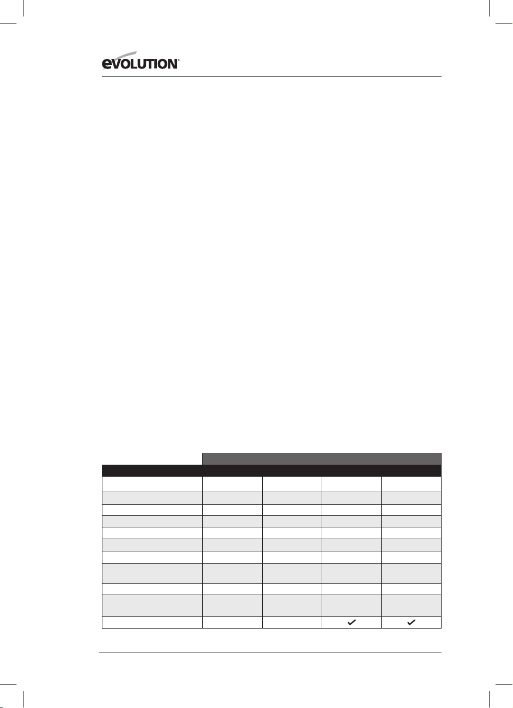
182
www.evolutionpowertools.com
(1.2) INTRODUCTIE
BELANGRIJK
Lees deze handleiding en veiligheidsvoorschriften
zorgvuldig en in zijn geheel door.
Bent u onzeker over hoe u bepaalde functies van dit
gereedschap moet gebruiken, dan is het voor uw eigen
veiligheid aanbevolen de relevante technische hulplijn te
raadplegen. U vindt het nummer hiervan op de website
van Evolution Power Tools. We bedienen meerdere
hulplijnen binnen onze wereldwijde organisatie. U
kunt voor technische hulp echter ook uw leverancier
raadplegen.
(1.3) CONTACT:
Web: www.evolutionpowertools.com
VK/EU/AUS: customer[email protected]
VS: evolutioninfo@evolutionpowertools.com
(1.4) GARANTIE
Gefeliciteerd met de aankoop van een Evolution Power
Tool apparaat. Registreer uw product online zoals
uitgelegd in de registratiefolder die bij de machine is
gevoegd. Dit stelt u in staat om de garantieperiode van
uw machine te valideren op de Evolution website door
uw gegevens in te voeren en zo een snelle service te
garanderen als u deze ooit nodig hebt.
We danken u hartelijk dat u heeft gekozen voor
een product van Evolution Power Tools.
SPECIFICATIES
VS
MACHINESPECIFICATIES R165CCSL R185CCS R185CCSX R185CCSX+
Model Nr: 026-0004 027-0004 027-0004C 027-0004A
Motor EU (220-240 V ~ 50 Hz)
Motor VK (110 V ~ 50 Hz)
Motor VS (120 V ~ 60 Hz) 10 A 15 A 15 A 15 A
Onbelast toerental (220-240 v)
Onbelast toerental (110v en 120v) 3900 min
-1
/ rpm 3700 min
-1
/ rpm 3700 min
-1
/ rpm 3700 min
-1
/ rpm
Gewicht 9,5 lb 10,8 lb 11,2 lb 11,2 lb
Max. afschuiningshoek zaagblad
(graden)
45˚ 60˚ 45˚ 45˚
Lengte netsnoer 10 ft 13 ft 13 ft 13 ft
Type cirkelzaagbasis Geperst staal
Gegoten
aluminium
Gegoten alumi-
nium
Gegoten
aluminium
Compatibel met zaagrail
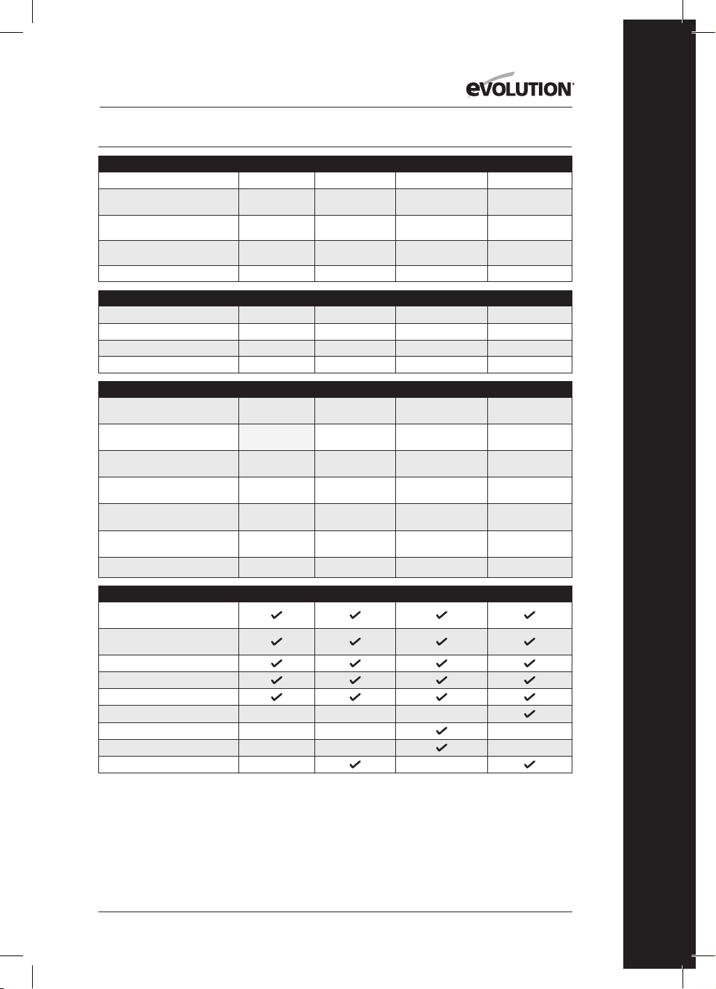
183
www.evolutionpowertools.com
NL
SNIJCAPACITEITEN R165CCSL R185CCS R185CCSX R185CCSX+
Zacht plaatstaal (maximale dikte) 1/8” 1/4” 1/4” 1/4”
Zacht plaatstalen kokerprofiel
(max. wanddikte)
1/8” 1/4” 1/4” 1/4”
Max. zaagdikte (0°) 2-3/32" 2-1/2”
2-1/2” (2-5/16” met
rail)
2-1/2” (2-5/16”
met rail)
Max. zaagdikte (45°) 1-11/32" 1-9/16”
1-13/16” (1-5/8”
met rail)
1-13/16” (1-5/8”
met rail)
Max. zaagdikte (60°) 1”
SPECIFICATIES ZAAGBLAD R165CCSL R185CCS R185CCSX R185CCSX+
Diameter zaagblad Ø 6-1/2” Ø 7-1/4” Ø 7-1/4” Ø 7-1/4”
Aantal tanden 14 20 16 20
Diameter boring 25/32” 25/32” 25/32” 25/32”
Kerf 1,7 mm 1,7 mm 1,7 mm 1,7 mm
GELUID EN TRILLINGEN R165CCSL R185CCS R185CCSX R185CCSX+
Geluidsdrukniveau L
pa
92,4 dB(A) K:3
dB(A)
97,3dB(A) K=3 dB(A) 97,3dB(A) K=3 dB(A) 97,3dB(A) K=3 dB(A)
Geluidsvermogensniveau L
wa
103,4 dB(A) K:3
dB(A)
105,3 dB(A) K=3
dB(A)
105,3 dB(A) K=3 dB(A)
105,3 dB(A) K=3
dB(A)
Trilling - Hoofdhandgreep
(houtzagen)
a
h,w
= 2,747 m/s
2
A
h,w
= 3,347 m/s
2
a
h,w
= 3,347 m/s
2
a
h,w
= 3,347 m/s
2
Trilling - Hulphandgreep
(houtzagen)
a
h,w
= 2,619 m/s
2
A
h,w
= 3,119 m/s
2
a
h,w
= 3,119 m/s
2
a
h,w
= 3,119 m/s
2
Trilling - Hoofdhandgreep
(metaalzagen)
a
h,M
= 2,302 m/s
2
a
h,M
= 3,572 m/s
2
a
h,M
= 3,572 m/s
2
a
h,M
= 3,572 m/s
2
Trilling - Hulphandgreep
(metaalzagen)
a
h,M
= 2,239 m/s
2
a
h,M
= 3,241 m/s
2
a
h,M
= 3,241 m/s
2
a
h,M
= 3,241 m/s
2
Onzekerheid K
1,5 m/s
2
1,5 m/s
2
1,5 m/s
2
1,5 m/s
2
GELEVERDE ITEMS R165CCSL R185CCS R185CCSX R185CCSX+
TCT-zaagblad voor meerdere
materialen
Inbussleutel (vervanging
zaagblad)
Parallelle randgeleider
Stofpoortadapter
Stofslangaansluiting
Draagkoffer
Zaagrail - 340 mm (13-3/8”) x3
Verbindingsstang en schroeven (x4)
Ledlampje

184
www.evolutionpowertools.com
VK/EU/AUS
R165CCSL R185CCS R185CCSX R185CCSX+
026-0001 / 026-0002 /
026-0003
027-0001C /
027-0002C / 027-0003C
027-0001 /
027-0002 / 027-0003
027-0001A /
027-0002A / 027-0003A
1200 W 1600 W 1600 W 1600 W
1200 W 1600 W 1600 W 1600 W
3700 min
-1
/ rpm 3900 min
-1
/ rpm 3900 min
-1
/ rpm 3900 min
-1
/ rpm
3700 min
-1
/ rpm 3700 min
-1
/ rpm 3700 min
-1
/ rpm 3700 min
-1
/ rpm
4,3 kg 4,9 kg 5,1 kg 5,1 kg
45˚ 60˚ 45˚ 45˚
3 m 3 m 3 m 4 m
Geperst staal Gegoten aluminium Gegoten aluminium Gegoten aluminium
R165CCSL R185CCS R185CCSX R185CCSX+
3 mm 6 mm 3 mm 6 mm
3 mm 6 mm 3 mm 6 mm
53 mm 64 mm 64 mm (59 mm met rail) 64 mm (59 mm met rail)
34 mm 40 mm 47 mm (42 mm met rail) 47 mm (42 mm met rail)
24 mm
R165CCSL R185CCS R185CCSX R185CCSX+
Ø 165 mm Ø 185 mm Ø 185 mm Ø 185 mm
14 20 16 20
20 mm 20mm 20 mm 20 mm
1,7 mm 1,7 mm 1,7 mm 1,7 mm
R165CCSL R185CCS R185CCSX R185CCSX+
92,4 dB(A) K:3 dB(A)
97,3dB(A) K=3 dB(A) 97,3dB(A) K=3 dB(A) 97,3dB(A) K=3 dB(A)
103,4 dB(A) K:3 dB(A) 105,3 dB(A) K=3 dB(A) 105,3 dB(A) K=3 dB(A) 105,3 dB(A) K=3 dB(A)
a
h,w
= 2,747 m/s
2
a
h,w
= 3,347 m/s
2
a
h,w
= 3,347 m/s
2
a
h,w
= 3,347 m/s
2
a
h,w
= 2,619 m/s
2
a
h,w
= 3,119 m/s
2
a
h,w
= 3,119 m/s
2
a
h,w
= 3,119 m/s
2
a
h,M
= 2,302 m/s
2
a
h,M
= 3,572 m/s
2
a
h,M
= 3,572 m/s
2
a
h,M
= 3,572 m/s
2
a
h,M
= 2,239 m/s
2
a
h,M
= 3,241 m/s
2
a
h,M
= 3,241 m/s
2
a
h,M
= 3,241 m/s
2
1,5 m/s
2
1,5 m/s
2
1,5 m/s
2
1,5 m/s
2
R165CCSL R185CCS R185CCSX R185CCSX+
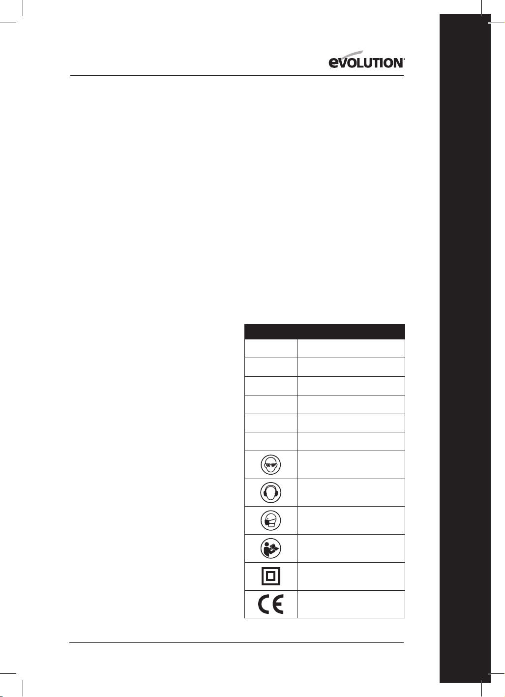
185
www.evolutionpowertools.com
NL
TRILLING
(1.5) Opmerking: De trillingsmeting is gedaan in
standaard omstandigheden in overeenstemming
met: EN 62841-1: 2015,
EN 62841-2-5: 2014
Waarschuwing: Draag gehoorbescherming!
De opgegeven totale trillingswaarde is gemeten
volgens een standaard testmethode en kan worden
gebruikt voor het vergelijken van het ene apparaat
met het andere.
De opgegeven totale trillingswaarde kan ook gebruikt
worden voor een voorlopige beoordeling van
blootstelling.
(1.6) WAARSCHUWING: Bij het gebruik van deze
machine kan de operator worden blootgesteld aan
intense trillingen, doorgegeven aan de hand en arm.
De bediener zou 'witte trillingsvingers' (ziekte van
Raynaud) kunnen ontwikkelen. Deze aandoening
kan de temperatuurgevoeligheid van de hand
verminderen
en gevoelloosheid veroorzaken.
Langdurige of regelmatige gebruikers van deze
machine moeten de toestand van hun handen en
vingers goed in de gaten houden. Indien een van
deze symptomen bij u optreedt, moet u onmiddellijk
een
arts raadplegen.
• De meting en beoordeling van de blootstelling
van de mens aan trillingen op de werkplek die
doorgegeven worden aan de hand, is te vinden in:
EN 62841-1 en EN 62841-2-5
• Vele factoren kunnen het niveau van de trillingen
tijdens het werk beïnvloeden; bv. de toestand
en opstelling van het werkoppervlak en het type
en de toestand van de gebruikte machine. Deze
factoren moeten voor elk gebruik geëvalueerd
worden, en waar mogelijk moet een aangepaste
werkwijze worden toegepast. Het goed omgaan
met deze factoren zal de effecten van trillingen
verminderen:
Hantering
• Hanteer de machine zorgvuldig
en laat de machine het werk doen.
• Vermijd het uitoefenen van overmatige fysieke
kracht op de besturingselementen.
• Let op uw veiligheid en stabiliteit, en de plaatsing
en richting van de machine tijdens het gebruik.
Werkoppervlak
• Houd goed rekening met het materiaal van het
werkoppervlak;
de toestand, dichtheid, sterkte,
stijfheid en oriëntatie.
WAARSCHUWING: De trillingsemissie tijdens
het daadwerkelijke gebruik van het elektrische
gereedschap kan afwijken van de aangegeven
totaalwaarde. Dit is afhankelijk van de manier waarop
het gereedschap gebruikt wordt.
De noodzaak veiligheidsmaatregelen te identificeren
en de operator te beschermen zijn gebaseerd op
een schatting van de blootstelling bij de werkelijke
gebruiksomstandigheden (met in achtneming van
alle onderdelen
van de werkcyclus, zoals de momenten waarop de
machine is uitgeschakeld, wanneer deze stationair
draait,
als aanvulling op de activeringstijd).
(1.7 ) LABELS EN SYMBOLEN
WAARSCHUWING: Dit apparaat niet gebruiken
als er enig waarschuwings- en/of instructielabel
ontbreekt of beschadigd is. Neem contact op met
Evolution
Power Tools voor vervangende labels.
Opmerking: Alle of sommige van de volgende
symbolen kunnen in de handleiding of op het
product getoond worden.
(1.8)
Symbool Omschrijving
V
Volt
A
Ampère
Hz
Hertz
Min
-1
/ RPM
Snelheid
~
Wisselstroom
n
o
Onbelast toerental
Draag een veiligheidsbril
Draag gehoorbescherming
Draag stofbescherming
Lees de instructies
Dubbel geïsoleerd
CE-certificatie
186
www.evolutionpowertools.com
UKCA-certificatie
ETL-certificatie
Afval van elektrische
en elektronische uitrusting
Triman - afvalophaling
en recycling
Waarschuwing
(RCM) Regulatory Compliance
Markering voor elektrische en
elektronische apparatuur.
Australische/Nieuw-Zeeland norm
(1.9) BEOOGD GEBRUIK
VAN DIT ELEKTRISCH GEREEDSCHAP
WAARSCHUWING: Dit product is een handbediende
cirkelzaag en is ontworpen om gebruikt te worden
met speciale zaagbladen van Evolution. Gebruik
alleen accessoires ontworpen voor deze machine en/
of specifiek aanbevolen
door Evolution Power Tools Ltd.
Indien uitgerust met een geschikt blad
kan deze machine gebruikt worden om het volgende
te zagen:
Zacht staal, plaatstaal, aluminium, hout
Opmerking: Het zagen van gegalvaniseerd staal kan
de levensduur van het zaagblad verkorten.
(1.10) VERBODEN GEBRUIK
VAN DIT ELEKTRISCH GEREEDSCHAP
WAARSCHUWING: Dit product is een handbediende
cirkelzaag en mag alleen als zodanig gebruikt
worden. Het mag op geen enkele manier worden
aangepast of worden gebruikt voor het aandrijven
van andere apparatuur of andere accessoires die niet
worden genoemd in deze gebruiksaanwijzing.
(1.11) WAARSCHUWING: Deze machine mag niet
worden gebruikt door personen (inclusief kinderen)
met verminderde lichamelijke, zintuiglijke
of mentale vaardigheden, of met een gebrek aan
kennis en ervaring, tenzij er toezicht op ze is of
ze instructies hebben ontvangen over het veilige
gebruik van de machine door een persoon die
verantwoordelijk is
voor hun veiligheid en bekwaam
is in het veilige gebruik.
Op kinderen dient toezicht te zijn
zodat ze geen toegang hebben tot en
niet gaan spelen met deze machine.
(1.12) ELEKTRISCHE VEILIGHEID
Deze machine is uitgerust met een voor de doelmarkt
geschikte aangegoten stekker en netsnoer. Als
het netsnoer is beschadigd, dient dit te worden
vervangen door een speciaal
snoer of samenstelling beschikbaar via de fabrikant
of de monteur.
(1.13) GEBRUIK BUITENSHUIS
WAARSCHUWING: Voor uw bescherming mag
dit gereedschap, indien het buitenshuis wordt
gebruikt, niet worden blootgesteld aan regen of
worden gebruikt in een vochtige omgeving. Plaats
het gereedschap niet op vochtige oppervlakken.
Gebruik een schone, droge werkbank indien deze
beschikbaar is. Gebruik voor extra bescherming
een aardlekschakelaar die de stroomtoevoer zal
onderbreken als de lekstroom groter is dan 30 mA
voor 30 ms. Controleer altijd de werking van de
aardlekschakelaar voordat u de machine gebruikt.
Indien een verlengsnoer nodig is moet het een
geschikt type zijn voor gebruik buitenshuis en van
een label zijn voorzien dat dit aangeeft.
De instructies van de fabrikant moeten worden
opgevolgd bij het gebruik van een verlengsnoer.
(2.1) ALGEMENE VEILIGHEIDSINSTRUCTIES
(Deze algemene veiligheidsinstructies zijn zoals
gespecificeerd in EN 62841-1: 2015).
WAARSCHUWING: Lees alle
veiligheidswaarschuwingen en -instructies. Het niet
opvolgen van waarschuwingen
en instructies kan leiden tot een elektrische schok,
brand en/of ernstig letsel.
Bewaar alle waarschuwingen en instructies
voor toekomstig gebruik. De term 'elektrisch
gereedschap'in de waarschuwingen verwijst naar uw
door stroom (met netsnoer) of door accu's gevoede
(snoerloos), elektrische gereedschap.
(2.2) 1) Algemene veiligheidswaarschuwingen
voor elektrisch gereedschap
[Werkplekveiligheid]
a) Houd uw werkplek schoon en goed verlicht.
Rommelige of donkere ruimten vragen om
ongelukken.
b) Gebruik elektrisch gereedschap niet in
een explosieve omgeving, zoals in de buurt
van ontvlambare vloeistoffen, gassen of stof.
Elektrische

187
www.evolutionpowertools.com
NL
gereedschappen maken vonken en kunnen het
stof of de dampen doen ontvlammen.
c) Houd kinderen en omstanders op een veilige
afstand tijdens het bedienen van elektrisch
gereedschap. Afleidingen kunnen tot controleverlies
leiden.
(2.3) 2) Algemene veiligheidswaarschuwingen
voor elektrisch gereedschap [Elektrische
veiligheid]
a) Stekkers van elektrisch gereedschap moeten op
het stopcontact passen. Pas de stekker nooit aan.
Gebruik geen adapters bij geaarde elektrische
gereedschappen. Ongewijzigde stekkers en
passende stopcontacten verminderen het risico op
elektrische schokken.
b) Vermijd lichamelijk contact met geaarde
oppervlakken zoals pijpen, radiatoren, fornuizen
en koelkasten. Er bestaat een verhoogd risico op
elektrische schokken als uw lichaam geaard is.
c) Stel uw elektrische gereedschap niet bloot
aan regen of een natte omgeving. Water in een
elektrisch gereedschap verhoogt het risico op
elektrische schokken.
d) Misbruik het snoer niet. Gebruik het snoer
nooit om een elektrisch gereedschap te dragen,
trekken of om de stekker uit het stopcontact te
halen. Houd het snoer uit de buurt van hitte, olie,
scherpe randen of bewegende delen. Beschadigde
of in de war geraakte snoeren vergroten het risico op
elektrische schokken.
e) Bij gebruik buitenshuis van een elektrisch
gereedschap dient u een snoer te gebruiken
dat hiervoor geschikt is. Een snoer dat geschikt is
voor gebruik buitenshuis vermindert het risico op
elektrische schokken.
f) Als het gebruik van een elektrisch gereedschap in
een vochtige omgeving onvermijdelijk is, gebruik
dan een door een aardlekschakelaar beveiligde
stroomvoorziening.
Het gebruik van een aardlekschakelaar (RCD)
vermindert het risico
op elektrische schokken.
Opmerking: Het product is enkel bedoeld voor
gebruik op locaties met een vermogenscapaciteit van
≥100A per fase, geleverd van een distributienetwerk
met een nominaal voltage van 230V. Indien nodig,
neem contact op met het energiebedrijf om u ervan
te verzekeren dat de netstroombelastbaarheid op het
aansluitpunt op het openbare net voldoende is om
het product aan te sluiten.
(2.4) 3) Algemene veiligheidswaarschuwingen
voor elektrisch gereedschap [Persoonlijke
veiligheid].
a) Blijf alert, let op wat u doet en gebruik uw
gezonde verstand bij het bedienen van elektrisch
gereedschap. Gebruik geen elektrisch gereedschap
als u moe bent of onder invloed van drugs, alcohol
of medicijnen. Een moment van onoplettendheid
tijdens het werken met elektrische gereedschappen
kan resulteren in ernstig persoonlijk letsel.
b) Gebruik persoonlijke beschermingsmiddelen.
Draag altijd oogbescherming. Veiligheidsuitrusting
zoals stofmasker, antislip veiligheidsschoenen, helm
of gehoorbescherming zullen persoonlijk letsel
verminderen,
indien deze worden gebruikt onder
de juiste omstandigheden.
c) Voorkom onbedoeld starten. Zorg ervoor
dat de schakelaar in de uit-positie staat voordat
u de stroomvoorziening en/of accu aansluit, het
gereedschap oppakt of draagt. Het dragen van
elektrisch gereedschap met uw vinger op de
schakelaar of het in het stopcontact steken van de
stekker met de schakelaar aan, is een
uitnodiging voor ongelukken.
d) Verwijder eventuele steeksleutels of andere
sleutels van de bladbout voordat u het elektrische
gereedschap inschakelt. Een op een bewegend
onderdeel van elektrisch gereedschap achtergelaten
moersleutel of andere sleutel kan tot persoonlijk
letsel leiden.
e) Reik niet te ver. Zorg dat u te allen tijde in
evenwicht blijft. Dat zorgt voor een betere controle
over het elektrische gereedschap in onverwachte
situaties.
f) Draag gepaste kleding. Draag geen loszittende
kleding of sieraden. Houd uw haar, kleding en
handschoenen uit de buurt van bewegende delen.
Loszittende kleding, sieraden of lang haar kunnen in
de bewegende delen terecht komen.
g) Als er voorzieningen zijn voor het aansluiten
van stofafzuiging en stofopvangvoorzieningen,
zorg er dan voor dat deze correct zijn aangesloten
en correct worden gebruikt. Het gebruik van
stofopvanging kan aan stof gerelateerde gevaren
verminderen.
h) Word niet zelfgenoegzaam door de ervaring
die u hebt opgedaan door het frequent gebruiken
van gereedschappen en laat u niet verleiden
de veiligheidsvoorschriften te negeren. Een
onachtzame actie kan in een fractie van een seconde
ernstig letsel veroorzaken.
(2.5) 4) Algemene veiligheidswaarschuwingen
voor elektrisch gereedschap [Gebruik en
onderhoud van elektrisch gereedschap].
a) Forceer het elektrisch gereedschap niet.
Gebruik het juiste elektrische gereedschap voor
uw toepassing. Het juiste elektrische gereedschap
zal de taak beter en veiliger en in het juiste tempo
uitvoeren, wanneer het wordt gebruikt waarvoor het
is ontworpen.
b) Gebruik het elektrisch gereedschap niet als de
aan/uit-schakelaar
niet in- of uitschakelt. Ieder elektrische gereedschap
dat niet bediend kan worden met de aan/uit-

188
www.evolutionpowertools.com
schakelaar
is gevaarlijk en moet worden gerepareerd.
c) Koppel het elektrische gereedschap los van
de stroomvoorziening van het elektrische
gereedschap voordat u aanpassingen aanbrengt,
accessoires verwisselt of elektrisch gereedschap
opbergt. Dergelijke veiligheidsmaatregelen
verminderen de kans dat het elektrische gereedschap
onbedoeld start.
d) Bewaar niet-gebruikte elektrische
gereedschappen buiten bereik van kinderen en
sta niet toe dat personen die niet bekend zijn met
het elektrische gereedschap of deze instructies
het elektrische gereedschap bedienen. Elektrische
gereedschappen zijn gevaarlijk in handen van
onervaren gebruikers.
e) Onderhoud uw elektrische gereedschappen.
Controleer op scheefstand of blokkering van
bewegende onderdelen,
breuk van bewegende onderdelen en enige andere
omstandigheid die de werking van het gereedschap
kan beïnvloeden. Bij schade moet het elektrische
gereedschap vóór gebruik gerepareerd worden.
Veel ongelukken worden veroorzaakt door slecht
onderhouden elektrische gereedschappen.
f) Houd snijgereedschappen scherp en schoon.
Op de juiste manier onderhouden
snijgereedschappen met
scherpe zaagtanden zijn minder geneigd tot
vastlopen
en zijn beter onder controle te houden.
g) Gebruik het elektrische gereedschap, de
accessoires en inzetgereedschappen etc., in
overeenstemming met deze instructies, rekening
houdend met de werkomstandigheden en het
werk dat moet worden uitgevoerd. Het elektrische
gereedschap gebruiken voor handelingen anders
dan bedoeld
kan leiden tot gevaarlijke situaties.
h) Houd de handgrepen en grijpoppervlakken
droog, schoon en vrij van olie en vet. Gereedschap
met gladde handgrepen en grijpoppervlakken zorgen
voor onveilig gebruik en gebrek aan controle in
onverwachte situaties.
(2.6) 5) Algemene veiligheidswaarschuwingen
voor elektrisch gereedschap
[Service]
a) Geef het elektrische gereedschap in onderhoud
bij een gekwalificeerde reparateur die alleen
originele onderdelen gebruikt. Dit waarborgt dat
de veiligheid van het elektrische gereedschap wordt
behouden.
(2.7) GEZONDHEIDSADVIES
WAARSCHUWING: Bij het gebruik van deze machine
kunnen stofdeeltjes vrijkomen. Afhankelijk van
de materialen waarmee u werkt, kan dit stof zeer
schadelijk zijn. Vraag professioneel advies indien u
denkt dat de verf waarmee het oppervlak van het
te zagen materiaal bedekt is, lood bevat. Verf op
loodbasis dient alleen te worden verwijderd door
een professional, en u moet deze niet
zelf proberen te verwijderen.
Wanneer het stof op oppervlakken neergedaald is,
kan contact van uw hand met uw mond leiden tot de
inname van lood. Blootstelling aan zelfs lage niveaus
van lood kan leiden tot onomkeerbaar hersenletsel en
beschadiging van het zenuwstelsel. Vooral jonge en
ongeboren kinderen zijn kwetsbaar.
We raden u aan de risico's verbonden aan de
materialen waarmee u werkt goed in te schatten en
het risico op blootstelling te beperken.
Sommige materialen kunnen stof produceren dat
gevaarlijk kan zijn voor uw gezondheid. We raden u
daarom aan bij het gebruik van deze machine een
goedgekeurd gezichtsmasker met verwisselbare filter
te dragen.
Bij het werken altijd goed letten op het
volgende:
• Werk in een goed-geventileerde ruimte.
• Werk met goedgekeurde veiligheidsuitrustingen,
zoals stofmaskers die speciaal ontworpen zijn om
microscopische deeltjes te filteren.
(2.8) WAARSCHUWING: De werking van elektrisch
of gemotoriseerd gereedschap kan ertoe leiden dat
er voorwerpen richting uw ogen worden geslingerd,
wat kan leiden tot ernstige oogschade. Voordat u het
elektrische gereedschap gebruikt, altijd een gesloten
veiligheidsbril, een veiligheidsbril met zijbescherming
of een volledig gelaatsscherm opzetten zoals nodig.
VEILIGHEIDSINSTRUCTIES VOOR ALLE ZAGEN
[Zaagprocedures]
a) GEVAAR: Houd uw handen uit de buurt van het
zaaggebied en het zaagblad. Houd uw tweede
hand op het extra handvat of de motorbehuizing
. Indien beide handen de zaag vasthouden, kunnen
ze niet door het zaagblad gesneden worden.
b) Reik niet onder het werkstuk. Onder het
werkstuk kan de beschermkap u niet beschermen
tegen het zaagblad.
c) Stem de zaagdiepte af op de dikte van het
werkstuk. Minder dan een volle tand van de
zaagbladtanden mag zichtbaar zijn onder het
werkstuk.
d) Houd het werkstuk nooit in uw handen of
over uw benen tijdens het zagen. Bevestig
het werkstuk op een stabiel platform. Het is
belangrijk om het werkstuk goed te ondersteunen
om blootstelling van het lichaam, vastlopen van
het zaagblad en controleverlies zo goed mogelijk te
minimaliseren.
e) Houd het elektrische gereedschap vast aan
geïsoleerde handgrepen bij werkzaamheden
waarbij de zaag in contact kan komen met

189
www.evolutionpowertools.com
NL
verborgen draden of zijn eigen snoer. Contact met
een onder spanning staande draad kan blootliggende
metalen delen van het elektrische gereedschap onder
spanning zetten en de gebruiker een elektrische
schok bezorgen.
f) Gebruik bij rippen oftewel in lengterichting
zagen altijd een rip-geleider of rechte-rand-
geleider. Dit verbetert de nauwkeurigheid van de
zaagsnede en vermindert de kans op vastlopen van
het zaagblad.
g) Gebruik altijd een zaagblad met het juiste
formaat en de juiste vorm asgaten (ruitvormig
versus rond). Zaagbladen die niet passen op de
montagedelen van de zaag, draaien niet correct,
waardoor u minder controle heeft.
h) Gebruik nooit beschadigde of onjuiste
sluitringen of bouten voor het zaagblad. De
sluitringen en bout van het zaagblad zijn speciaal
ontworpen voor uw zaag, voor maximale prestaties
en een veilige werking.
(3.2) [Oorzaken van terugslag en
gerelateerde waarschuwingen]
Terugslag is een plotselinge reactie op een bekneld,
vastgelopen of verkeerd uitgelijnd zaagblad,
waardoor de onbeheerste zaag omhoog schiet uit het
werkstuk, richting de bediener.
Als het zaagblad vast komt te zitten of vastloopt in de
zich sluitende zaagspleet, blokkeert het zaagblad en
wordt het door de motorreactie met grote snelheid in
de richting van de bediener gestoten.
Indien het zaagblad verdraaid of verkeerd uitgelijnd
in de snede komt te zitten, kunnen de tanden
aan de achterkant van het zaagblad zich in het
bovenoppervlak van het werkstuk graven, waardoor
de zaag de zaagsnede uitklimt en terugspringt naar
de bediener toe.
(3.3)
Terugslag is het resultaat van verkeerd gebruik
van de zaag en/of onjuiste werkprocedures of
-omstandigheden die voorkomen kunnen worden
door de hiernavolgende voorzorgsmaatregelen te
nemen.
a) Houd de zaag stevig met uw beide handen vast
en plaats uw armen zodanig dat u weerstand tegen
een mogelijke terugslag kunt bieden. Zorg dat uw
lichaam aan een van de zijkanten van het zaagblad
is, maar niet op één lijn (voor of achter) met het
zaagblad. Terugslag kan de zaag naar achteren doen
springen, maar de krachten van de terugslag kunnen
door de bediener opgevangen worden, indien de
juiste voorzorgsmaatregelen worden genomen.
b)Indien het zaagblad vastloopt, of wanneer u een
snede onderbreekt om wat voor reden dan ook,
laat dan de aan/uit-schakelaar los en houd de zaag
bewegingloos in het materiaal totdat het zaagblad
helemaal tot stilstand gekomen is. Probeer de zaag
niet uit het werk te verwijderen en trek de zaag
niet terug zolang het zaagblad nog in beweging is,
want dan kan zich terugslag voordoen. Onderzoek
de oorzaak en onderneem corrigerende acties om de
oorzaak van het vastlopen van de zaag te elimineren.
c) Wanneer u de zaag in een werkstuk herstart,
plaats het zaagblad dan zodanig in de zaagsnede
dat de zaagtanden geen contact met het materiaal
hebben. Indien het zaagblad vastloopt wanneer
de zaag herstart wordt, kan het omhoog lopen en
terugslaan vanuit het werkstuk.
d) Gebruik geen botte of beschadigde zaagbladen.
Onscherpe of verkeerd ingestelde zaagbladen
produceren een nauwe zaagsnede, wat kan leiden tot
overmatige wrijving, vastlopen van het zaagblad en
terugslag.
e) Vergrendelhendels voor de zaagbladdiepte en
de afschuiningsafstelling moeten stevig en veilig
vastzitten voordat u een snede maakt. Indien de
zaagbladafstelling verschuift tijdens het zagen, kan
dat vastlopen en terugslag veroorzaken.
f) Vergrendelinghendels voor de zaagbladdiepte
en de afstelling afschuining moeten strak en veilig
vastzitten voordat u een snede maakt. Indien de
zaagbladafstelling verschuift tijdens het zagen, kan
dat vastlopen en terugslag veroorzaken.
g) Wees extra voorzichtig bij het zagen in
bestaande muren en andere zones met onbekende
risico's. Het vooruitstekende zaagblad kan objecten
raken die terugslag kunnen veroorzaken.
FUNCTIONEREN ONDERSTE BESCHERMKAP
a) Controleer of de onderste beschermkap
correct sluit vóór ieder gebruik. Bedien de zaag
niet indien de onderste beschermkap niet vrij
beweegt of niet direct sluit. U mag de onderste
beschermkap nooit in open positie klemmen of
vastbinden. Indien de zaag per ongeluk is gevallen,
kan de onderste beschermkap verbogen zijn.
Breng de onderste beschermkap omhoog met de
terugtrekhendel en controleer dat de beschermkap
vrij kan bewegen en geen contact maakt met de zaag
of andere onderdelen, bij alle hoeken en dieptes van
de snede.
b) Controleer de werking van de veer van de
onderste beschermkap. Indien de beschermkap
of veer niet correct functioneert, moeten ze
vóór verder gebruik onderhouden worden. De
onderste beschermkap kan traag werken vanwege
beschadigde onderdelen, kleverige aanslag of
opgehoopt zaagafval.
c) De onderste beschermkap mag alleen
handmatig ingetrokken worden voor speciale
snedes zoals invalzaagsnedes en samengestelde
snedes. Breng de onderste beschermkap omhoog
met de terugtrekhendel en laat de onderste
beschermkap los zodra het zaagblad het materiaal
ingaat. Voor alle andere zaaghandelingen moet de
onderste beschermkap automatisch werken.

190
www.evolutionpowertools.com
d) Zorg altijd dat de onderste beschermkap
het zaagblad bedekt voordat u de zaag op de
werkbank of de vloer legt. Een onbeschermd
lopend zaagblad zal ervoor zorgen dat de zaag naar
achteren gaat bewegen dan daarbij snijdt in alles wat
zich op zijn weg bevindt. Houd er rekening mee dat
de zaag niet onmiddellijk stopt nadat de aan/uit-
schakelaar losgelaten is.
EXTRA VEILIGHEIDSINSTRUCTIES
VOOR CIRKELZAGEN
a) Gebruik geen snelstaal (HSS, High Speed Steel)
zaagbladen.
b) Inspecteer de machine en het zaagblad
vóór elk gebruik. Gebruik geen vervormde,
gebarsten, verweerde of anderszins beschadigde
zaagbladen.
c) Gebruik de zaag nooit zonder het originele
beschermkapsysteem. Nooit
de beschermkap in de open positie vastzetten.
Zorg ervoor dat de beschermkap vrij kan bewegen
zonder geblokkeerd te worden.
d) Gebruik enkel zaagbladen die overeenkomen
met de
in deze handleiding omschreven kenmerken.
Voordat u accessoires gebruikt, vergelijk altijd
de maximaal toegestane RPM van het
accessoire met de RPM van de machine.
e) Gebruik geen slijpschijven.
f) Gebruik alleen zaagbladen met (een)
diameter(s) overeenkomstig
de markeringen.
(3.4) WAARSCHUWING: als er onderdelen
ontbreken, gebruik dan de machine niet totdat de
ontbrekende onderdelen zijn vervangen. Het niet
opvolgen van deze regel kan leiden tot ernstig
lichamelijk letsel.
(4.1) AAN DE SLAG - UITPAKKEN
Waarschuwing: Deze verpakking bevat scherpe
voorwerpen. Wees voorzichtig bij het uitpakken.
Verwijder de machine, samen met de meegeleverde
accessoires, uit de verpakking. Controleer zorgvuldig
of de machine zich in goede conditie bevindt en
controleer of alle accessoires die in deze handleiding
worden genoemd aanwezig zijn. Zorg er ook voor dat
alle accessoires compleet zijn.
Indien er onderdelen ontbreken, moeten het apparaat
en zijn accessoires samen in hun originele verpakking
geretourneerd worden aan de leverancier (retailer).
Gooi de verpakking niet weg. Bewaar deze zorgvuldig
tijdens de garantieperiode. Gooi de verpakking op
een milieuverantwoorde manier weg. Recycle indien
mogelijk.
Laat kinderen niet met de lege plastic zakjes spelen, in
verband met verstikkingsgevaar.
(4.3) EVOLUTION GEBRUIKSAANWIJZINGEN
Evolution Power Tools levert bij elk product een
gebruiksaanwijzing.
Elke gebruiksaanwijzing is met zorg samengesteld
en ontwikkeld om toegankelijke, bruikbare
informatie te bieden over veilig gebruik, zorg voor en
onderhoud van het product. Door de informatie in de
gebruiksaanwijzing door te nemen, kan de bediener
het potentieel van de machine veilig en geheel
benutten.
Het beleid van Evolution met betrekking tot
continue ontwikkeling kan betekenen dat, met enige
regelmaat, de inhoud van een gebruiksaanwijzing
niet volledig overeenkomt met de recentste
verbeteringen of upgrades die zijn doorgevoerd voor
een bepaald product. Upgrades/verbeteringen aan
de specificatie van een product kunnen zijn ontstaan
door technologische vooruitgang of veranderingen in
het wetgevingskader van het land van ontvangst, enz.
Als u twijfelt over een aspect van het gebruik van,
de zorg voor en onderhoud van een product van
Evolution, neem dan contact op met de relevante
hulplijn van Evolution, waar de recentste informatie
en extra advies wordt verstrekt.

191
www.evolutionpowertools.com
NL
13
15
4
14
5
1
3
8
9
10
11
6
7
2
16
12
1. UITWERPOPENING ZAAGMATERIAAL
2. DUIMHENDEL
3. TCT-ZAAGBLAD VOOR MEERDERE
MATERIALEN
4. ONDERSTE BESCHERMKAP
5. PARALLELLE RANDGELEIDER
6. ERGONOMISCH HANDVAT VOOR
7. KOOLBORSTELS
8. 8 MM INBUSSLEUTEL (VERVANGING
ZAAGBLAD)
9. VERGRENDELHENDEL DIEPTEAFSTELLING
10. DIEPTESCHAAL
11. ACHTERSTE HANDGREEP
12. BOVENSTE BESCHERMKAP
13. PRECISIE-ONTWORPEN BODEMPLAAT
14. DUIMHENDEL
15. GRADENSCHAAL
16. ASVERGRENDELINGSKNOP
17. STOFPOORTADAPTER
18. 25/32” BINNENSTE ZAAGBLADFLENS
19. 5/8” BINNENSTE ZAAGBLADFLENS
VS
17
18
19

192
www.evolutionpowertools.com
VS
1. UITWERPOPENING ZAAGMATERIAAL
2. DUIMHENDEL
3. TCT-ZAAGBLAD VOOR MEERDERE
MATERIALEN
4. ONDERSTE BESCHERMKAP
5. PARALLELLE RANDGELEIDER
6. ERGONOMISCH HANDVAT VOOR
7. KOOLBORSTELS
8. 5/16” INBUSSLEUTEL (VERVANGING
ZAAGBLAD)
9. VERGRENDELHENDEL DIEPTEAFSTELLING
10. DIEPTESCHAAL
11. ACHTERSTE HANDGREEP AAN-/
UITSCHAKELAAR
12. BOVENSTE BESCHERMKAP
13. PRECISIE-ONTWORPEN BODEMPLAAT
14. SCHUININGSAANPASSING DUIMHENDEL
15. GRADENSCHAAL
16. ASVERGRENDELINGSKNOP
17. LEDLAMPJE
18. STOFPOORTADAPTER
19. 25/32” BINNENSTE ZAAGBLADFLENS
20. 5/8” BINNENSTE ZAAGBLADFLENS
13
15
17
18
19
20
4
14
5
1
3
8
9
10
11
6
7
2
16
12
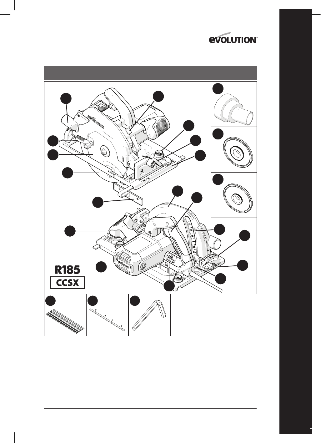
193
www.evolutionpowertools.com
NL
VS
1. UITWERPOPENING
ZAAGMATERIAAL
2. DUIMHENDEL
3. TCT-ZAAGBLAD VOOR
MEERDERE MATERIALEN
4. ONDERSTE BESCHERMKAP
5. PARALLELLE RANDGELEIDER
6. ERGONOMISCH HANDVAT
VOOR
7. KOOLBORSTELS
8. 5/16” INBUSSLEUTEL
(VERVANGING ZAAGBLAD)
9. DIEPTE-AANPASSINGSHENDEL
10. DIEPTESCHAAL
11. ACHTERSTE HANDGREEP AAN-/
UITSCHAKELAAR
12. BOVENSTE BESCHERMKAP
13. PRECISIE-ONTWORPEN
RAILCOMPATIBELE
BODEMPLAAT
14. DUIMHENDEL
15. ACHTERSTE GRADENSCHAAL
16. ASVERGRENDELINGSKNOP
17. STOFPOORTADAPTER
18. 25/32” BINNENSTE
ZAAGBLADFLENS
19. 5/8” BINNENSTE
ZAAGBLADFLENS
20. DRAAIKNOPPEN
RAILAANPASSING
21. DUIMSCHROEF ACHTERSTE
AFSCHUINING
22. 3x 13-3/8” RAIL
23. 4 x VERBINDINGSSTANGEN RAIL
24. 1/8” INBUSSLEUTEL (RAIL)
13
20
15
17
18
19
4
14
5
1
3
8
9
10
21
11
6
7
2
16
12
22 23 24

194
www.evolutionpowertools.com
VS
1. UITWERPOPENING ZAAGMATERIAAL
2. DUIMHENDEL
3. TCT-ZAAGBLAD VOOR MEERDERE
MATERIALEN
4. ONDERSTE BESCHERMKAP
5. PARALLELLE RANDGELEIDER
6. ERGONOMISCH HANDVAT VOOR
7. KOOLBORSTELS
8. 8 MM INBUSSLEUTEL (VERVANGING
ZAAGBLAD)
9. VERGRENDELHENDEL DIEPTEAFSTELLING
10. DIEPTESCHAAL
11. ACHTERSTE HANDGREEP AAN-/
UITSCHAKELAAR
12. BOVENSTE BESCHERMKAP
13. PRECISIE-ONTWORPEN RAILCOMPATIBELE
BODEMPLAAT
14. DUIMHENDEL
15. ACHTERSTE GRADENSCHAAL
16. ASVERGRENDELINGSKNOP
17. LEDLAMPJE
18. STOFPOORTADAPTER
19. 25/32” BINNENSTE ZAAGBLADFLENS
20. 5/8” BINNENSTE ZAAGBLADFLENS
21. DRAAIKNOPPEN RAILAANPASSING
22. DUIMSCHROEF ACHTERSTE AFSCHUINING
13
21
15
17
18
19
20
4
14
5
1
3
8
9
10
22
11
6
7
2
16
12

195
www.evolutionpowertools.com
NL
13
15
4
14
5
1
3
8
9
10
11
6
7
2
16
12
1. UITWERPOPENING ZAAGMATERIAAL
2. DUIMHENDEL
3. TCT-ZAAGBLAD VOOR MEERDERE
MATERIALEN
4. ONDERSTE BESCHERMKAP
5. PARALLELLE RANDGELEIDER
6. ERGONOMISCH HANDVAT VOOR
7. KOOLBORSTELS
8. 8 MM INBUSSLEUTEL (VERVANGING
ZAAGBLAD)
9. VERGRENDELHENDEL DIEPTEAFSTELLING
10. DIEPTESCHAAL
11. ACHTERSTE HANDGREEP MET
GEÏNTEGREERDE
VEILIGHEIDSSTART AAN-/UITSCHAKELAAR
12. BOVENSTE BESCHERMKAP
13. PRECISIE-ONTWORPEN BODEMPLAAT
14. DUIMHENDEL
15. GRADENSCHAAL
16. ASVERGRENDELINGSKNOP
VK/EU/AUS

196
www.evolutionpowertools.com
1. UITWERPOPENING ZAAGMATERIAAL
2. DUIMHENDEL
3. TCT-ZAAGBLAD VOOR MEERDERE
MATERIALEN
4. ONDERSTE BESCHERMKAP
5. PARALLELLE RANDGELEIDER
6. ERGONOMISCH HANDVAT VOOR
7. KOOLBORSTELS
8. 8 MM INBUSSLEUTEL (VERVANGING
ZAAGBLAD)
9. VERGRENDELHENDEL DIEPTEAFSTELLING
10. DIEPTESCHAAL
11. ACHTERSTE HANDGREEP MET
GEÏNTEGREERDE
VEILIGHEIDSSTART AAN-/UITSCHAKELAAR
12. BOVENSTE BESCHERMKAP
13. PRECISIE-ONTWORPEN BODEMPLAAT
14. DUIMHENDEL
15. GRADENSCHAAL
16. ASVERGRENDELINGSKNOP
17. STOFPOORTADAPTER
VK / EU
13
15
17
4
14
5
1
3
8
9
10
11
6
7
2
16
12
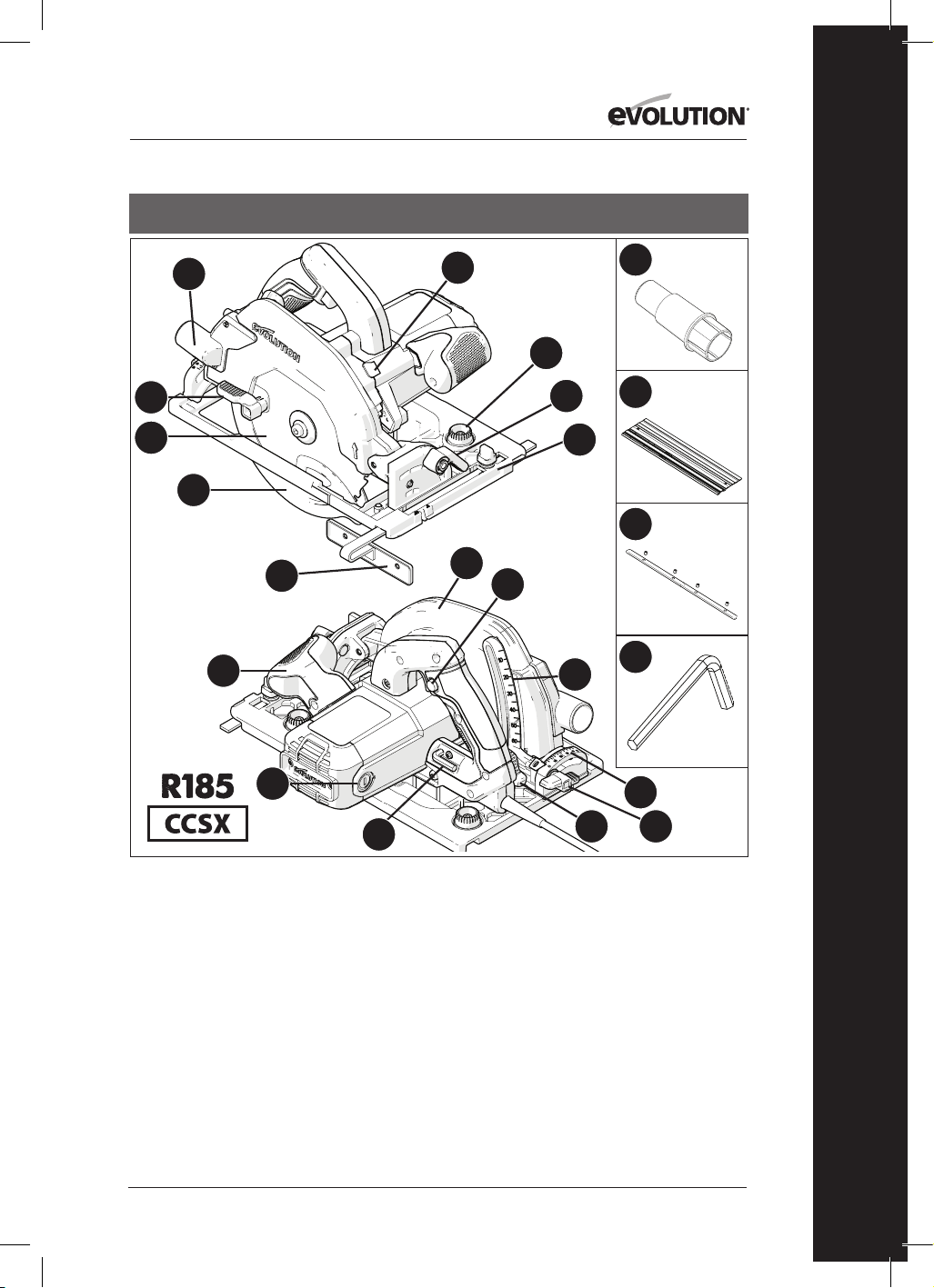
197
www.evolutionpowertools.com
NL
13
18
15
17
20
21
22
4
14
5
1
3
8
9
10
19
11
6
7
2
16
12
1. UITWERPOPENING ZAAGMATERIAAL
2. DUIMHENDEL
3. TCT-ZAAGBLAD VOOR MEERDERE
MATERIALEN
4. ONDERSTE BESCHERMKAP
5. PARALLELLE RANDGELEIDER
6. ERGONOMISCH HANDVAT VOOR
7. KOOLBORSTELS
8. 8 MM INBUSSLEUTEL (VERVANGING
ZAAGBLAD)
9. VERGRENDELHENDEL DIEPTEAFSTELLING
10. DIEPTESCHAAL
11. ACHTERSTE HANDGREEP MET
GEÏNTEGREERDE
VEILIGHEIDSSTART AAN-/UITSCHAKELAAR
12. BOVENSTE BESCHERMKAP
13. PRECISIE-ONTWORPEN RAILCOMPATIBELE
BODEMPLAAT
14. DUIMHENDEL
15. ACHTERSTE GRADENSCHAAL
16. ASVERGRENDELINGSKNOP
17. STOFPOORTADAPTER
18. DRAAIKNOPPEN RAILAANPASSING
19. DUIMSCHROEF ACHTERSTE AFSCHUINING
20. 3 x 340 mm RAIL
21. 4 x VERBINDINGSSTANGEN RAIL
22. 3 mm INBUSSLEUTEL
VK / EU

198
www.evolutionpowertools.com
VK / EU
1. UITWERPOPENING ZAAGMATERIAAL
2. DUIMHENDEL
3. TCT-ZAAGBLAD VOOR MEERDERE
MATERIALEN
4. ONDERSTE BESCHERMKAP
5. PARALLELLE RANDGELEIDER
6. ERGONOMISCH HANDVAT VOOR
7. KOOLBORSTELS
8. 8 MM INBUSSLEUTEL (VERVANGING
ZAAGBLAD)
9. VERGRENDELHENDEL DIEPTEAFSTELLING
10. DIEPTESCHAAL
11. ACHTERSTE HANDGREEP MET
GEÏNTEGREERDE
VEILIGHEIDSSTART AAN-/UITSCHAKELAAR
12. BOVENSTE BESCHERMKAP
13. PRECISIE-ONTWORPEN RAILCOMPATIBELE
BODEMPLAAT
14. DUIMHENDEL
15. ACHTERSTE GRADENSCHAAL
16. ASVERGRENDELINGSKNOP
17. STOFPOORTADAPTER
18. DRAAIKNOPPEN RAILAANPASSING
19. ACHTERSTE AFSCHUININGSDUIMSCHROEF
13
18
15
17
4
14
5
1
3
8
9
10
19
11
6
7
2
16
12
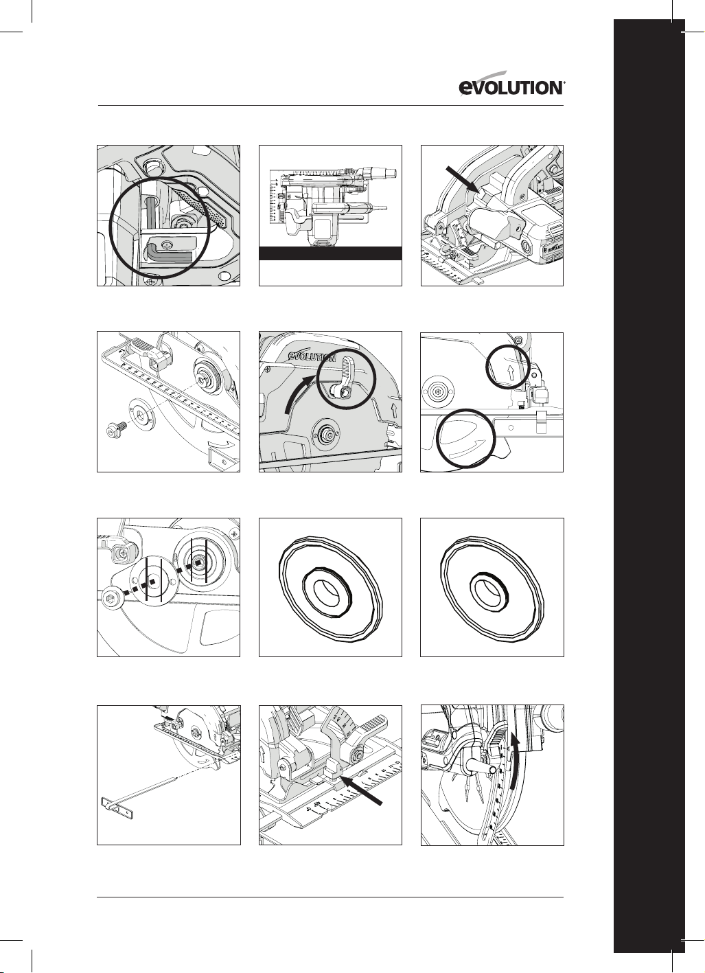
199
www.evolutionpowertools.com
NL
Afb. 3Afb. 2
Afb. 4
Afb. 1
Afb. 8
Afb. 6Afb. 5
Afb. 9
Afb. 10
Afb. 7a Afb. 7b Afb. 7c
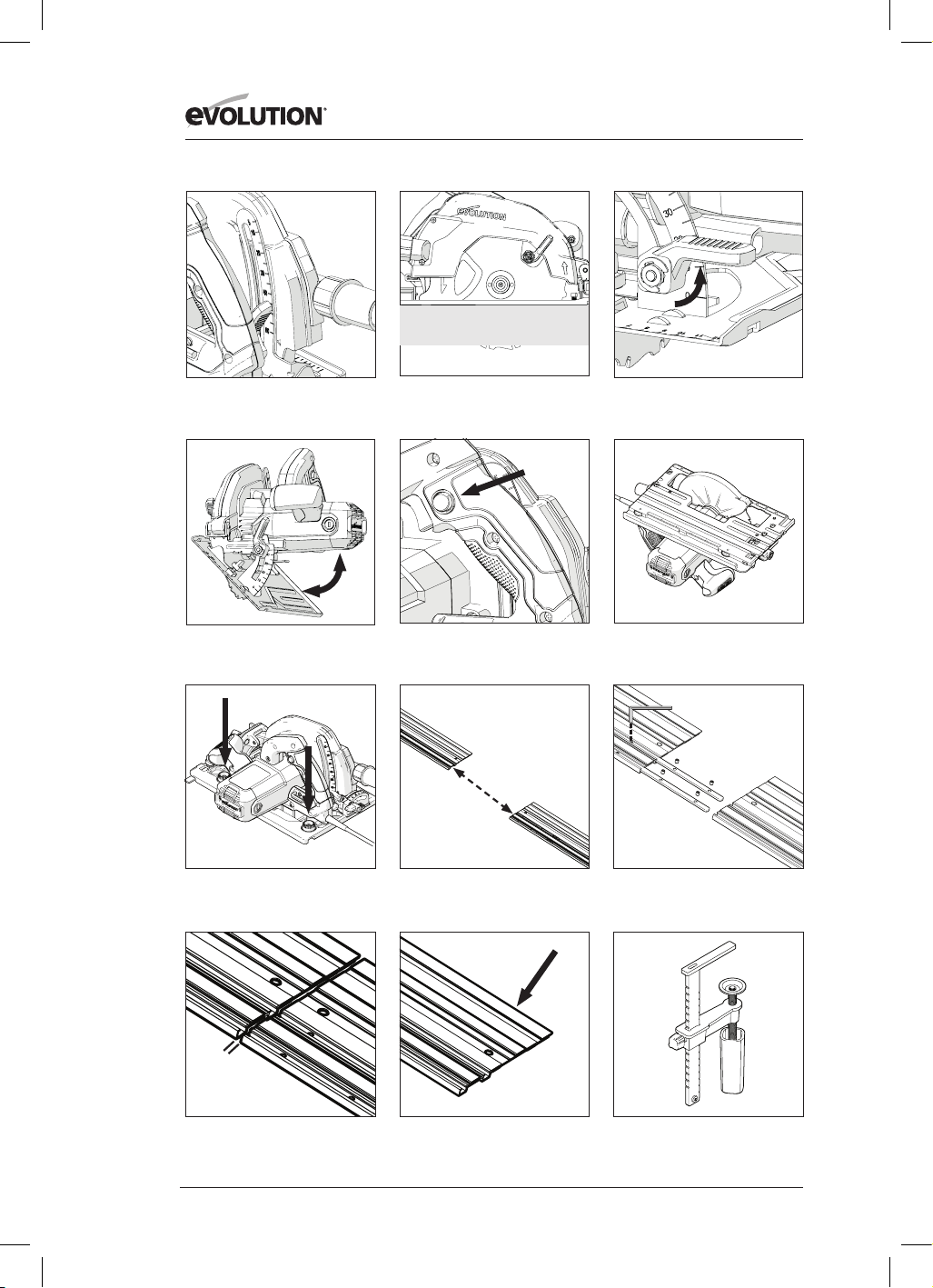
200
www.evolutionpowertools.com
Afb. 11
Afb. 12
Afb. 13
Afb. 14
Afb. 15
Afb. 16
Afb. 17 Afb. 18
Afb. 21Afb. 20
Afb. 19
Afb. 22
1 -2 mm

201
www.evolutionpowertools.com
NL
Afb. 27Afb. 26
Afb. 25
Afb. 30 Afb. 31
Afb. 34
Afb. 24Afb. 23
US stofpoortadapter
EU stofpoortadapter
Afb. 28
Afb. 29
Afb. 32 Afb. 33

202
www.evolutionpowertools.com
(10) VOORBEREIDING
WAARSCHUWING: Ontkoppel altijd de
stroomvoorziening naar de machine voordat u
eventuele aanpassingen aanbrengt.
Opmerking: Deze machines zijn uitgerust met
goedgekeurde netsnoer en stekker voor het
beoogde land van gebruik. Pas het netsnoer op
geen enkele manier aan.
(10.1) PLAATSEN/
VERWIJDEREN VAN EEN ZAAGBLAD
WAARSCHUWING: Gebruik alleen originele
zaagbladen van Evolution (of die door
Evolution Power Tools zijn goedgekeurd), die
zijn ontworpen voor gebruik in deze machines.
Zorg ervoor dat de maximale snelheid van het
blad compatibel is met de machine. Voer deze
handeling alleen uit wanneer de machine is
losgekoppeld van de stroomvoorziening.
Opmerking: Aanbevolen wordt dat de bediener
beschermende handschoenen draagt bij het
hanteren van het zaagblad bij de installatie en
bij het vervangen van het zaagblad.
• Zoek de meegeleverde zaagbladwissel-
inbussleutel op, die zich in het opbergvak van
de machine bevindt (vergelijkbare positie bij
alle machines). (Afb. 1)
• Plaats de zaag op een stevig, vlak oppervlak.
Opmerking: Alle machines kunnen,
voorzichtig, neergezet worden op de vlakke
kant van de motorbehuizing, (Afb. 2) voor
gemakkelijke toegang tot het zaagblad en de
zaagbladbevestigingen.
• Zoek de asvergrendelingsknop van de
machine op (vergelijkbare positie bij alle
machines). Vergrendel de as van de machine
met de asvergrendelingsknop. (Afb. 3).
Opmerking: Langzaam met de hand draaien
van het zaagblad en ondertussen licht drukken
op de asvergrendelingsknop zal helpen bij het
inschakelen van de asvergrendeling.
• Gebruik de inbussleutel om de inbusbout, de
bijbehorende bevestigingen en de buitenste
zaagblad-aandrijfflens los te maken en te
verwijderen. (Afb. 4)
Opmerking: De inbusschroef is uitgerust met
een standaard schroefdraad.
Draai de schroef met de klok mee om aan te
draaien. Draai de schroef tegen de klok in om los
te draaien.
• Berg de buitenste zaagbladfles en de
bijbehorende bevestigingen veilig op.
• Draai de onderste beschermkap omhoog in
de bovenste beschermkap, met behulp van
de handmatige duimhendel. (Afb. 5)
• Haal het zaagblad (indien geplaatst)
voorzichtig uit de machine.
• Reinig de binnenste en buitenste zaagblad-
aandrijfflenzen grondig.
Opmerking: De binnenste zaagbladfles kan
indien gewenst op zijn plek blijven zitten,
maar deze moet wel goed worden nagekeken
en goed worden schoongemaakt. Als hij uit
de machine is verwijderd, moet hij weer in
dezelfde richting worden teruggeplaatst als hij
zat vóór de verwijdering.
• Reinig het zaagblad grondig rondom de
boring (beide oppervlakken) waar de
zaagbladflens het zaagblad zal aanraken en
vastklemmen.
• Plaats het (nieuwe) zaagblad.
• Controleer dat de op het blad geprinte
draairichtingspijlen overeenkomen met
de draairichtingspijlen op de bovenste en
onderste beschermkap van de machine.
(Afb. 6)
• Plaats de buitenste aandrijfflens, de
asinbusschroef en de bijbehorende
bevestigingen terug.
Opmerking: De buitenste aandrijfflens heeft
een speciaal bewerkte boring met twee
tegenovergestelde 'vlakken'. (Afb. 7a) Deze
passen op twee complementaire 'vlakken' in
de as-schacht van de machine.
• Plaats de asvergrendeling terug en draai de
inbusschroef goed aan met de inbussleutel.
• Laat de asvergrendelingsknop los
• Berg de inbussleutel weer op, op de
daarvoor bestemde opbergplek.
• Controleer of de asvergrendeling volledig
los is door het zaagblad handmatig te
draaien.
• Controleer de werking van de onderste
zaagbladbeschermkap.
Opmerking: Enkel voor de Noord-
Amerikaanse markt is een dubbelzijdige
asflens inbegrepen, voor zaagbladen met een
boring van 1” (Afb. 7b) en zaagbladen met
een boring van 5/8” (Afb. 7c).
(11) PARALLELLE RANDGELEIDER

203
www.evolutionpowertools.com
NL
Een parallelle randgeleider (Afb. 8), die vooral
handig kan zijn bij 'rippen", oftewel schulpen of
in de lengterichting zagen, wordt meegeleverd
bij alle CCS-machines. De geleider kan worden
geplaatst aan de voorkant van de bodemplaat.
De arm van de geleider moet door de
rechthoekige sleuven aan weerszijden
(voorkant) van de geperste stalen bodemplaat
worden gestoken en onder de centraal
geplaatste afstellingsborgschroef worden
geschoven. (Afb. 9)
Opmerking: De parallelle randgeleider kan
aan beide zijden van de bodemplaat worden
geplaatst.
WAARSCHUWING: Bevestig en verstel de
geleider alleen als de machine losgekoppeld is
van de stroomvoorziening.
Opmerking: De arm van de parallelle
randgeleider moet door alle rechthoekige
sleuven in de bodemplaat gaan.
WAARSCHUWING: Het kan gevaarlijk zijn om
de randgeleider te plaatsen en proberen te
gebruiken terwijl de arm slechts door één (1)
van de rechthoekige sleuven in de bodemplaat
van de machine gaat.
Pas de randgeleider zodanig aan dat deze de
vereiste afstand tot het zaagblad aanhoudt en
draai de afstelschroef aan. Controleer dat de
randgeleider parallel met het zaagblad is.
(12) AANPASSING ZAAGDIEPTE
Opmerking: De algemene afstelling van
de zaagdiepte wordt op alle CCS machines
gedaan met behulp van dezelfde onderdelen
en dezelfde basistechniek voor het instellen
van de zaagbladdiepte.
• Maak het vergrendelingsmechanisme
voor diepteaanpassing los door de
bedieningshendel omhoog te trekken. (Afb.
10)
• Verstel de bodemplaat om de vereiste
zaagdiepte te verkrijgen (hoe ver het
zaagblad door de bodemplaat uitsteekt).
Opmerking: De diepteschaal bevindt zich
op de diepte-instellingskwadrant, met een
overeenkomstige markering geïntegreerd
in het aangrenzende deel van de bovenste
beschermkap van de machine. (Afb. 11)
Gebruiken van deze functies kan het instellen
helpen versnellen.
Opmerking: Hoewel de diepteschaal en
markering zeer nuttig zijn, en ze een snelle
diepte-instelling mogelijk maken, moet het
gebruik ervan altijd worden beschouwd als
een hulpmiddel voor de instelling die ermee
bereikt kan worden.
Als een zeer nauwkeurige zaagdiepte is
vereist, moet de zaagbladinstelling worden
gecontroleerd met een precisie-liniaal
voor ingenieurs (niet meegeleverd) of iets
vergelijkbaars en overeenkomstig worden
aangepast.
• In de meeste gevallen moet de zaagdiepte
worden ingesteld op de dikte van het te
zagen materiaal, plus de diepte van een
halve zaagtand (punt van de tand tot het
beginpunt van de tand). (Afb.12)
• Zet het diepteafstellingsmechanisme
vast door de vergrendelhendel omlaag
te duwen, om de machine veilig in de
gewenste stand te vergrendelen.
(13) AANPASSING ZAAGHOEK
(AFSCHUINING)
Alle CCSL- en CCSX-machines hebben de
mogelijkheid om het zaagblad (tot) 45˚ te
kantelen en alle CCS-machines hebben de
mogelijkheid om het zaagblad (tot) 60˚ te
kantelen aan de linkerzijde.
Afgeschuind zagen is hierdoor mogelijk.
Opmerking: Het zaagblad bevindt zich in
verticale positie wanneer de gradenschaal op
0˚ staat.
Opmerking: Een gradenschaal (0˚-
45˚ of 0˚- 60˚) is geïntegreerd in het
hoekvergrendelingskwadrant aan de voorkant
van de bodemplaat. Deze kan gebruikt worden
om snel hoeken te bepalen, maar moet als
slechts een leidraad gezien worden.
Als een zeer nauwkeurige afschuiningshoek
vereist is, moet de zaagbladinstelling worden
gecontroleerd met een precisiehoekmeter
zoals een nonius-hoekmeter (niet
meegeleverd) en overeenkomstig worden
aangepast.
• Maak het
afschuiningsvergrendelmechanisme aan
de voorkant van de machine los door de
hendel naar boven te trekken. (Afb. 13)
• Kantel het zaagblad in de gewenste hoek
zoals aangegeven op de gradenboog van de
gradenschaal. (Afb. 14)

204
www.evolutionpowertools.com
• Maak het
afschuiningsvergrendelmechanisme goed
vast zodra de gewenste afschuiningshoek
is bereikt door de hendel naar beneden te
duwen.
(14) GEBRUIKSADVIES
(CHECKS VÓÓR GEBRUIK)
Opmerking: Omdat alle gebruiksomgevingen
uniek en divers zijn, biedt Evolution Power
Tools het volgende algemene advies over
veilige gebruiksprocedures en praktijken aan
de gebruiker.
Dit advies kan niet uitputtend zijn omdat
Evolution geen invloed heeft op het type
workshop of werkomgeving waarin deze
machines gebruikt kunnen worden.
We raden aan dat de gebruiker advies
inwint bij een bevoegde autoriteit of de
workshopsupervisor bij onzekerheid over enig
aspect van het gebruik van deze machines.
Het is belangrijk dat de routine-
veiligheidschecks uitgevoerd worden (vóór
ieder gebruik) voordat de bediener de machine
gaat gebruiken.
WAARSCHUWING: De veiligheidschecks
vóór gebruik moeten uitgevoerd worden
als de machine losgekoppeld is van de
stroomvoorziening.
• Controleer dat alle beschermkappen correct
functioneren, en dat alle afstel-hendels/
schroeven goed vastgezet zijn.
• Controleer dat het zaagblad correct
geïnstalleerd is. Controleer ook of u het
juiste zaagblad hebt gekozen voor het
materiaal dat wordt gezaagd.
• Controleer de deugdelijkheid van het
netsnoer.
• Indien mogelijk, klem het werkstuk vast op
een stevige stijve ondersteuningsstructuur,
zoals een werkbank, zaagbok of iets
vergelijkbaars.
• De gebruiker moet zich altijd bewust zijn
van de positie en richting en route van het
netsnoer.
(15) PBM
• De gebruiker moet alle relevante PBM
(Persoonlijke beschermingsmiddelen)
dragen die nodig zijn voor de taak.
Dit kunnen een veiligheidsbril,
volledig gelaatsmasker, stofmasker,
veiligheidsschoenen enz. zijn.
Opmerking: Alle machines van de CCS-serie
zijn uitgerust met een blazer die vuil van de
snijlijn verwijdert. De blazer stuurt lucht vanaf
een met een motor aangedreven ventilator
richting het gebied aan de voorkant van het
zaagblad, waardoor de zaaglijn relatief vrij
van zaagafval blijft. Deze functie helpt het
zicht van de bediener te verbeteren en de
voortgang van het zaagblad te volgen, waarbij
markeringslijnen zichtbaar blijven.
WAARSCHUWING: Alle veroorzaakte stof is
mogelijk schadelijk voor de gezondheid.
Sommige materialen kunnen erg schadelijk
zijn, en de gebruiker dient altijd een
stofmasker te dragen dat geschikt is voor het
materiaal waarmee wordt gewerkt.
Er dient professionele hulp en advies worden
ingeschakeld indien de gebruiker niet zeker is
van de mogelijke giftigheid van het te zagen
materiaal.
WAARSCHUWING: Deze machines moeten
nooit gebruikt worden om asbest of enig
materiaal dat asbest bevat, of waarvan
vermoed wordt dat het asbest bevat, te zagen.
Raadpleeg/informeer de relevante autoriteiten
en win aanvullend advies in als de verdenking
van verontreiniging door asbest bestaat.
(16) AAN/UIT-SCHAKELAAR
Opmerking: Alle machines bestemd voor de
Europese en Australische markt zijn uitgerust
met een 'veiligheidsstart'-schakelaar om de
veiligheid van de gebruiker te verbeteren.
(Afb. 15)
Om de motor te starten:
• Duw met uw duim op de
veiligheidsvergrendelingsknop aan de
zijkant van de handgreep.
• Druk de aan/uit-schakelaar in.
Om de motor te stoppen:
• Laat de aan/uit-schakelaar los.
WAARSCHUWING: De motor mag nooit
worden gestart met het zaagblad in
rechtstreeks contact met enig oppervlak van
het werkstuk.
Opmerking: Machines bestemd voor de

205
www.evolutionpowertools.com
NL
Noord-Amerikaanse markt hebben een AAN-/
UIT-schakelaar zonder een ‘veiligheidsstart’-
schakelaar.
WAARSCHUWING: Als de zaag 'actief' is
(ledlampje ‘AAN’), vermijd dan onbedoeld
starten van de motor bij het optillen van de
machine van een werkbank of dergelijke. Per
ongeluk indrukken van de AAN-/UIT-schakelaar
(op de hoofdhandgreep) bij het optillen van de
machine, veroorzaakt starten van de motor.
ZAAGRAILS
Evolution machines van de serie CCSX
(raadpleeg de specificatiepagina voor
toepasselijke modellen) zijn ontworpen
op zo’n manier dat ze compatibel zijn met
zaagrails.
Opmerking: Elke cirkelzaag die met een
zaagrail kan worden gebruikt, heeft een groef
langs de onderkant van de bodemplaat (Afb.
16)
Evolution machines die zodanig zijn uitgerust
kunnen worden bevestigd aan en gebruikt
met de meeste zaagrails (geleiders) die
tegenwoordig te koop zijn.
Opmerking: Raadpleeg de met de rail
meegeleverde documentatie van de fabrikant.
In de meegeleverde documentatie staan
normaal gesproken de montage-instructies
voor de rail, evenals instructies over veilig
werken die moeten worden toegepast bij het
gebruik van dergelijke apparatuur.
Zaagrails kunnen worden toegepast indien:
• Het gebruik van een afkort- of cirkelzaag
gezondheids- en veiligheidsproblemen
of andere praktische problemen op de
werkplek kan veroorzaken. Bijvoorbeeld
bij het werken op een bouwplaats waar
zeer zorgvuldige, nauwkeurige controle
noodzakelijk kan zijn (werken op een dak of
op een steiger, enz.), kan het gebruiken van
een zaagrails de gebruiker extra (en veilige)
gebruiksmogelijkheden bieden.
• Nauwkeurig zagen van grote werkstukken
vereist is, dwars of in de lengte. Bijvoorbeeld
bij kozijnen, grote platen of wandpanelen
enz. kan een zaagrails/geleider de noodzaak
om een cirkelzaag te gebruiken in 'vrije
hand'-modus elimineren.
Opmerking: Zaagrail-compatibele machines
van Evolution hebben twee (2) nokken die
uitsteken in het kanaal van de bodemplaat
(een aan elk uiteinde).
'Draaiknoppen' (Afb. 17) stellen de gebruiker
in staat deze nokken te draaien.
Aanpassen van deze nokken zal de effectieve
breedte van het kanaal van de bodenplaat iets
verminderen.
Dit kan nodig zijn om kleine breedtevariaties
van de rail te compenseren, die tijdens de
productie kunnen optreden bij de extrusie.
De breedtes van zaagrails van verschillende
fabrikanten kunnen ook iets verschillen.
Opmerking: De gebruiker dient deze nokken
zodanig aan te passen dat wanneer de
machine correct op een rail is geplaatst, de
machine gemakkelijk en soepel naar voren en
naar achteren kan worden verplaatst zonder
dat enige zijdelingse beweging (wiebelen)
waarneembaar is.
EVOLUTION ZAAGRAILS
Sommige Evolution machines (afhankelijk van
het model en bestemmingsmarkt) worden
geleverd met een zaagrail.
Opmerking: Evolution zaagrails zijn
beschikbaar als aankoopoptie voor klanten.
Neem contact op met uw leverancier of
Evolution Power Tools voor meer informatie.
DE RAILS
Het Evolution railsysteem bestaat uit twee (2)
of drie (3) precisie-geëxtrudeerde delen.
(Afb. 18) Deze delen moeten met elkaar
worden verbonden met gebruik van de
meegeleverde verbindingsstangen. (Afb. 19)
Om de delen te verbinden (Afb. 19):
• Schuif de stangen in de T-sleuven op het
onderoppervlak van de extrusies.
• Zorg ervoor dat een gelijke lengte
(ongeveer) van de stangen in de beide te
verbinden delen gestoken wordt.
• Draai de stel-inbusschroeven aan om de
delen vast te zetten.
Opmerking: Het is belangrijk om een kleine
opening van 1 tot 2 mm over te houden tussen
de verbonden delen.
Dit zorgt ervoor dat wanneer een cirkelzaag
wordt geplaatst op en gebruikt met een
Evolution dwarszaagrails, de zaag soepel zal

206
www.evolutionpowertools.com
glijden over de hele lengte van de rails.
INBEDRIJFSSTELLING ZAAG MET
RAILS
Opmerking: De volgende richtlijnen hebben
betrekking op Evolution cirkelzagen en
de Evolution zaagrails. Raadpleeg de door
de fabrikant bij de zaag en/of de zaagrails
meegeleverde informatie als een niet van
Evolution afkomstige cirkelzaag of zaagrails zal
worden gebruikt.
Voordat de Evolution zaagrails voor het eerst
wordt gebruikt, moet de splinterbeschermstrip
(Afb. 21) uitgelijnd worden met de zaag en het
zaagblad.
Om de zaag uit te lijnen met de rails:
• Monteer de zaagrails volledig.
• Raadpleeg het hoofdstuk ‘Plaatsen en
vastzetten van de rails’. Klem de rails
vast aan een geschikt stuk reserve- of
schrootmateriaal.
• Stel het zaagblad in op een diepte die
geschikt is voor het gekozen proefwerkstuk.
• Zorg ervoor dat er geen obstakels aanwezig
zijn onder het pad van het zaagblad.
• Raadpleeg het hoofdstuk ‘Plaatsen en
vastzetten van de rails’. Plaats de cirkelzaag
correct op de rails.
• Start de motor en laat hem zijn volledige
snelheid bereiken.
• Schuif de cirkelzaag gelijkmatig en
langzaam over de volle lengte van de
rail totdat het zaagblad over de gehele
lengte van de splinterbeschermstrip heeft
doorgesneden.
Opmerking: Deze procedure past een
specifieke zaag aan een specifieke rail aan.
Als er een andere zaag wordt gebruikt
op de voorbereide rails, biedt de
splinterbeschermstrip mogelijk niet dezelfde
mate van bescherming als de specifieke zaag
voor de railconfiguratie.
Opmerking: De splinterbeschermstrip moet
beschouwd worden als een slijtageonderdeel.
Mettertijd vertoont de strip slijtage en
afvreting en moet is vervanging noodzakelijk.
De strip moet mogelijk ook vervangen worden
als er een andere cirkelzaag of ander zaagblad
(een met een andere kerfbreedte) dan de
oorspronkelijke toegewezen zaag moet
worden gebruikt.
VERVANGBARE
SPLINTERBESCHERMSTRIP
Als slijtageonderdeel moet de vervangbare
splinterbeschermstrip regelmatig worden
gecontroleerd op beschadiging of slijtage.
Vervang de strip als er schade of aanzienlijke
slijtage te zien is.
Vervangende strips zijn verkrijgbaar.
Raadpleeg uw leverancier of neem contact op
met Evolution via de juiste hulplijn.
De meegeleverde vervangbare
splinterbeschermstrip is een directe
vervanging voor het gemonteerde origineel.
Trek gewoon de oude strip voorzichtig van de
rail en vervang door de nieuwe strip.
Opmerking: Als er een nieuwe strip wordt
aangebracht, moet het afstemmingsproces
met zaag en rail worden herhaald.
EVOLUTION RAIL-KLEMMEN
(AFZONDERLIJK TE KOOP)
De Evolution snelklem (Afb. 22) is speciaal
ontworpen voor de Evolution zaagrails.
Opmerking: Extra klemmen kunnen worden
gekocht via Evolution Power Tools of uw lokale
leverancier.
Evolution klemmen passen in en
kunnen glijden langs de T-sleuven in het
onderoppervlak van de extrusies. (Afb. 23)
Dit stelt de gebruiker in staat de klemmen te
plaatsen (er is er een vereist aan elk uiteinde
van de rail) in posities die maximale veiligheid
en rigiditeit van de zaagrails voor het werkstuk
bieden.
PLAATSEN EN VASTZETTEN VAN DE
RAILS
Opmerking: De volgende richtlijnen
worden als advies gegeven: Evolution heeft
geen invloed over de werkomgeving en
omstandigheden waarin dit product wordt
gebruikt.
WAARSCHUWING: Als dit product wordt
gebruikt op een bouwplaats, dient de
gebruiker de relevante persoon met de
verantwoordelijkheid voor gezondheid en
veiligheid te raadplegen voor specifieke
veiligheidsvereisten of instructies ‘op locatie’.
• Markeer het werkstuk goed en dan met name
de zaaglijn waarlangs het zaagblad zich moet

207
www.evolutionpowertools.com
NL
verplaatsen.
• Monteer de zaagrails met zoveel delen als
vereist om het werkstuk op te spannen, met
een marge voor de benodigde oversteek.
• Met Evolution snelklemmen (heeft de
voorkeur) of geschikte G-klemmen de rails op
het werkstuk plaatsen en vastzetten door de
klemmen aan te spannen.
• Zorg ervoor dat de rand van de
splinterbeschermstrip precies langs de
gemarkeerde zaaglijn loopt.
WAARSCHUWING: De zaagrails moet over het
werkstuk uitsteken bij de beginrand. (Afb. 24)
De onderste beschermkap moet handmatig
worden ingetrokken en naar boven gedraaid
worden in de bovenste beschermkap terwijl de
cirkelzaag op de rails wordt geplaatst.
WAARSCHUWING: In deze positie ligt het
zaagblad bloot. DRUK NIET op de aan/uit-knop
totdat de volgende veiligheidschecks zijn
uitgevoerd.
EEN ZAAGSNEDE MAKEN
Een zaagsnede maken met een zaagrails is
vergelijkbaar met gewoon zagen met een
cirkelzaag. Alle veiligheidsprocedures en
-protocollen die van toepassing zijn op het
gebruiken van een cirkelzaag zijn ook van
toepassing wanneer een dergelijke zaag wordt
gebruikt met een dwarszaagrail.
De volgende richtlijnen, hoewel niet
allesomvattend, bieden algemeen advies:
• Voer een veiligheidscheck uit om er zeker
van te zijn dat de zaagrail goed is bevestigd
aan het werkstuk en dat het werkstuk zelf
stevig vastzit en niet kan verschuiven tijdens
het zagen.
• Controleer dat er zich geen obstakels onder
het werkstuk bevinden die de voortgang
van het zaagblad zouden kunnen afremmen
of hinderen of schade zouden kunnen
oplopen door het zaagblad.
• Zorg dat het netsnoer zodanig loopt dat het
geen struikelgevaar (of ander gevaar) vormt.
Controleer vooral dat het netsnoer niet in
contact kan komen met het draaiende blad
van de zaag.
• De gebruiker dient te zorgen voor een
stevige stabiele houding, stevig op de
voeten, met goed evenwicht en volledige
controle tijdens de gehele zaagsnede.
Voorzichtigheid is vooral noodzakelijk als
het zaagblad het werkstuk verlaat.
WAARSCHUWING: Vooral als er op hoogte
wordt gewerkt (en mogelijk bij andere
omstandigheden) moet er voor worden
gezorgd dat voorkomen wordt dat gezaagd
materiaal valt en dan letsel zou kunnen
toebrengen aan omstanders. De gebruiker
dient een manier te bedenken om dergelijk
gezaagd materiaal vast te houden of op
te vangen. Raadpleeg de persoon die
verantwoordelijk is voor de veiligheid op
locatie voor specifiek advies.
Opmerking: De gebruiker dient te overwegen
een proefsnede uit te voeren terwijl de zaag
niet aangesloten is op de stroomvoorziening,
als bevestiging dat de zaagprocedure geheel
veilig verloopt.
Wanneer de zaagsnede is voltooid, dient de
gebruiker de AAN/UIT-schakelaar los te laten,
te wachten tot de motor stopt en het zaagblad
tot stilstand gekomen is.
Als de zaag wordt opgetild van de zaagrails en
het werkstuk, zal de onderste beschermkap
automatisch naar beneden klappen en het
zaagblad geheel bedekken.
OPVANGEN VAN STOF/ZAAGAFVAL
Een adapter-opzetstuk (Afb. 25) kan op
alle CCS-machines worden geplaatst. Door
plaatsing van het opzetstuk kan de machine
worden aangesloten op een afvoersysteem
voor stof en zaagafval.
Opmerking: Het exacte ontwerp van het
meegeleverde opzetstuk verschilt, afhankelijk
van het type model en de doelmarkt van de
machine.
Op het meegeleverde opzetstuk passen veel
verschillende verkrijgbare afvoersystemen
voor stof en zaagafval. Het opzetstuk dient te
worden geplaatst op de uitwerpopening voor
het zaagmateriaal. (Afb. 26)
Opmerking: U kunt een afzuiginstallatie voor
stof/zaagafval op het verlengstuk aansluiten
indien nodig. Volg de instructies op van de
fabrikant van een dergelijke installatie op en
zorg dat u er zeker van bent, dat de installatie
het uitgeworpen zaagafval kan verwerken.
LEDLAMPJE
Sommige van deze machines (afhankelijk van
het model en de bestemmingsmarkt) worden

208
www.evolutionpowertools.com
geleverd met een automatisch ledlampje.
Opmerking: Als u niet zeker weer welke
functies uw machine heeft, raadpleeg dan de
specificatiepagina van deze handleiding.
Het ledlampje bevindt zich aan de linkerkant
(LH) van het zaagblad. (Afb. 27)
De straal van het ledlampje licht aan de
linkerzijde van het zaagblad op en verlicht
ook op het werkstuk aanwezige markeringen.
Dit moet de gebruiker helpen bij het
voorspellen van het pad van het zaagblad
door het werkstuk en helpen om efficiëntie,
nauwkeurigheid en veiligheid te bereiken.
Opmerking: Het ledlampje werkt automatisch.
Zodra de machine is aangesloten op een
stroomvoorziening is het ledlampje actief.
Dit geeft de gebruiker een duidelijke visuele
indicatie dat de machine succesvol is
aangesloten op het stroomnet en daardoor
wordt gevoed ('actief' is) en klaar is om te
beginnen met zagen.
Opmerking: Er zijn geen door te gebruiker te
onderhouden onderdelen in het ledlampje
en de straalrichting is een fabrieksinstelling.
De beschermende lensafdekking dient
vrij te worden gehouden van stof, enz.
(zie Onderhoud) om ervoor te zorgen dat
maximale helderheid van de lichtstraal wordt
behouden.
WAARSCHUWING: Maak de lensafdekking
enkel schoon wanneer de machine is
losgekoppeld van de stroomvoorziening en
het zaagblad volledig stilstaat.
INGEBOUWDE
ZAAGHULPMIDDELEN
Alle Evolution cirkelzagen zijn uitgerust met
diverse zaaghulpen of zaaggeleiders om de
gebruiker te helpen snel, nauwkeurig en veilig
te zagen.
Opmerking: Niet alle van de volgende functies
zijn te vinden op elke machine.
0˚ en 45˚ zaaglijngeleiders (Afb. 28)
Aan de voorste rand van de bodemplaat van
de machine bevinden zich twee (2) kleine
inkepingen, bij sommige machines aangeduid
met een hoekcijfer. Deze inkepingen geven
de positie van het zaagblad aan als het
zaagblad het werkstuk verlaat wanneer de
afschuiningshoek is ingesteld op 0˚ (zaagblad
verticaal) of op een hoek van 45˚.
Voorkant van de zaagbladgeleiding (Afb. 29)
Opmerking: Evolution machines die
compatibel zijn met Evolution zaagrails
hebben een inkeping aan de rechterzijde (RH)
van de gegoten bodemplaat.
De inkeping geeft de positie van de voorste
rand van het zaagblad aan wanneer het
zaagblad is ingesteld op maximale zaagdiepte.
Deze functie kan worden gebruikt bij het
plaatsen en positioneren van het zaagblad op
een zaagrail.
WAARSCHUWING: Het is belangrijk dat de
onderste beschermkap of zaagblad geen
enkel oppervlak van het werkstuk raakt tijdens
de initiële positionering van de zaag op de
zaagrails.
Liniaalgeleiders (Afb. 30)
Sommige Evolution cirkelzagen bevatten
liniaalgeleiders. Ze bevinden zich langs de
voorkant en/of zijkanten van de bodemplaat.
Deze geleiders kunnen een handige geschatte
positie of voorspelling van het zaagblad in het
werkstuk aangeven.
GESPECIALISEERDE AFSTELLINGEN
Uw Evolution machine heeft veel nauwkeurig
ontworpen componenten en instellingen,
waarvan de meeste fabrieksinstellingen zijn
en zijn aangepast voor langdurige consistente
nauwkeurigheid.
Onderhoud en aanpassingen aan deze
componenten of instellingen zullen
waarschijnlijk niet nodig zijn. Als onderhoud
of aanpassingen (na intensief gebruik) geacht
wordt nodig te zijn, beveelt Evolution aan dat
u contact opneemt met de technische hulplijn
voor advies en begeleiding.
Opmerking: Bepaalde aanpassingsprocedures
zijn enkel mogelijk met bepaalde
gespecialiseerde kennis en/of apparatuur.
(17) ALGEMEEN ZAAGADVIES
WAARSCHUWING: De gebruiker dient
altijd op de hoogte te zijn van de positie en
richting van het netsnoer. Het snoer dient op
zo’n manier te lopen dat het zaagblad niet in
contact kan komen met het netsnoer.
Het snoer dient geen struikelgevaar te
veroorzaken (of ander gevaar) voor de
gebruiker of omstanders.
• Forceer de machine niet.
• Laat de snelheid van het zaagblad zijn werk
doen. Door uitoefenen van overmatige druk
op de machine worden zaagprestaties niet

209
www.evolutionpowertools.com
NL
beter en de levensduur van het zaagblad
wordt erdoor verkort.
• Bij gebruik van de parallelle randgeleider
ervoor zorgen dat deze parallel met het
zaagblad is. Het zaagblad en/of de motor
kunnen beschadigd raken als de machine
gebruikt wordt met een niet correct
afgestelde parallelle randgeleider.
• Plaats de voorkant van de bodemplaat haaks
op het werkstuk. Voordat u de motor start,
moet u ervoor zorgen dat het blad geen
contact maakt met het werkstuk.
• Let er bij het beginnen van een zaagsnede
op dat u het zaagblad langzaam in het
materiaal brengt, zodat de tanden van het
blad niet worden beschadigd.
Opmerking: Aan de voorkant van de
bodemplaat van de CCSL-machine zijn twee (2)
zaaggeleidelijnen aangebracht (alleen voor 0°
en schuine hoeken van
45°).
• Gebruik beide handen om de zaag
voorwaarts door het werkstuk te bewegen.
• Oefen een soepele, constante druk uit om
de zaag voorwaarts door het werkstuk te
bewegen.
Opmerking: Alle machines van de CCS-
serie hebben een automatische onderste
beschermkap met een speciaal gevormde
voorrand. Deze feature zorgt ervoor dat
de beschermkap soepel en moeiteloos
ingetrokken wordt wanneer het zaagblad het
werkstuk ingaat. Als het zaagblad het werkstuk
verlaat, keert de onderste beschermkap
automatisch terug naar zijn normale positie
waarbij het zaagblad volledig wordt afgedekt.
Opmerking: In sommige gevallen, bijv. bij
een invalzaagsnede in een vloer of muur,
kan het nuttig zijn de onderste beschermkap
handmatig in te trekken.
Op de onderste beschermkap zit een met
de duim te bedienen hendel. Met de nodige
voorzichtigheid kan een vakkundige ervaren
bediener de beschermkap handmatig
intrekken, geheel of gedeeltelijk, zodat
invalzaagsnedes gemaakt kunnen worden.
WAARSCHUWING: Bij het handmatig
intrekken van de beschermkap is grote
voorzichtigheid geboden. Let bijzonder goed
op dat de hand of vingers van de bediener het
zaagblad nergens raken.
Als de zaagsnede voltooid is:
• Laat de AAN/UIT-knop los.
• Wacht tot het zaagblad helemaal
stilstaat.
• Verwijder de machine uit het werkstuk.
Laat daarbij de onderste beschermkap
automatisch terugkeren in zijn normale
positie waarbij het zaagblad wordt afgedekt.
WAARSCHUWING: Als de motor stopt of
hapert terwijl u probeert een zaagsnede
te maken, laat dan de AAN-/UIT-knop
onmiddellijk los. Koppel de machine los van de
stroomvoorziening en verwijder de machine
van het werkstuk. Onderzoek de oorzaak van
het probleem en verhelp deze indien mogelijk.
Probeer de motor alleen opnieuw te starten als
u er absoluut zeker van bent dat dit veilig is.
UITWERPOPENING
ZAAGMATERIAAL
WAARSCHUWING: Gebruik de stofzak en
de stofpoortadapter niet bij het zagen van
metalen materialen of hout met spijkers.
(18) ONDERHOUD EN AFSTELLINGEN
De 0˚ (zaagblad verticaal) positie kan
aangepast worden.
WAARSCHUWING: De machine dient
losgekoppeld te zijn van de stroomvoorziening
bij het uitvoeren van deze procedure.
Om de 0°-positie
te controleren:
• Zet het blad in stand 0° met het
kantelmechanisme tegen de stop.
• Controleer het blad ten opzichte van
de bodemplaat met behulp van een
precisie-winkelhaak of haakse liniaal (niet
meegeleverd). Let op dat u de TCT-punten
van de tanden niet raakt. Het zaagblad moet
precies in een hoek van 90° ten opzichte van
de bodemplaat staan.
Opmerking: Draai de onderste beschermkap
(handmatig) in de bovenste beschermkap. Dit
helpt bij het nauwkeurig positioneren van de
haakse liniaal en dus bij het controleproces.
Als aanpassing noodzakelijk is:
R165CCSL en 185CCS
Draai de stelschroef (Afb. 31) met de klok
mee of tegen de klok in met een inbussleutel

210
www.evolutionpowertools.com
van 4 mm (niet meegeleverd) tot het blad
exact in een hoek van 90° ten opzichte van de
bodemplaat staat.
R185CCSX en 185CCSX+
Draai de stelschroeven (Afb. 32) met de klok
mee of tegen de klok in met een inbussleutel
van 3 mm (niet meegeleverd) tot het blad
exact in een hoek van 90° ten opzichte van de
bodemplaat staat.
Om de 45˚-positie
te controleren (R185CCSX en
185CCSX+):
• Zet het blad in stand 45° met het
kantelmechanisme tegen de stop.
• Controleer het blad ten opzichte van
de bodemplaat met behulp van een
precisie-winkelhaak of haakse liniaal (niet
meegeleverd). Let op dat u de TCT-punten
van de tanden niet raakt. Het zaagblad moet
precies in een hoek van 45° ten opzichte van
de bodemplaat staan.
Draai de stelschroeven (Afb. 33) met de klok
mee of tegen de klok in met een inbussleutel
van 3 mm (niet meegeleverd) tot het blad
exact in een hoek van 45° ten opzichte van de
bodemplaat staat.
(19) CONTROLEREN EN VERVANGEN
VAN DE KOOLBORSTELS
WAARSCHUWING: Koppel het apparaat
los van de stroomvoorziening voordat u de
koolborstels controleert of vervangt.
Opmerking: Vervang beide koolborstels als
een of allebei minder dan 6 mm lang zijn, of als
de veer of draad is beschadigd of verbrand.
Om de borstels te verwijderen:
• Schroef de kunststof doppen aan de
achterkant van de motorbehuizing los.
(Afb. 34) Wees voorzichtig, want de doppen
kunnen veerbelast zijn.
• Trek de borstels met hun veren naar buiten.
• Als vervanging noodzakelijk is, vernieuw
dan de borstels en plaats de doppen terug.
Opmerking: Gebruikte, maar nog bruikbare
borstels kunnen worden teruggeplaatst, maar
alleen als ze weer in dezelfde positie worden
teruggeplaatst en
op dezelfde manier, in dezelfde richting, als ze
stonden voordat ze werden verwijderd uit de
machine.
• Laat de motor van de machine circa 5
minuten onbelast draaien. Dit helpt de
nieuwe borstels 'in te bedden' of 'in te
slijten', zodat u er zeker van kunt zijn dat de
motor efficiënt draait.
• Er kunnen vonken zichtbaar zijn totdat de
borstels volledig zijn ingebed.
(20) ALGEMEEN ONDERHOUD
EN SCHOONMAKEN
Opmerking: Elk onderhoud moet worden
uitgevoerd met de machine uitgeschakeld en
losgekoppeld van de stroomvoorziening.
• Controleer regelmatig of alle
veiligheidsfuncties en beschermkappen
goed werken. Gebruik deze machine
alleen indien alle beschermkappen/
veiligheidsfuncties goed werken.
• Alle motorlagers in deze machine zijn
levenslang gesmeerd. Er is geen verdere
smering vereist.
Gebruik een schone, licht vochtige doek voor
het schoonmaken van de kunststof onderdelen
van de machine. Gebruik geen oplosmiddelen
of dergelijke producten die de kunststof
onderdelen kunnen beschadigen.
Verwijder alle stof of andere verontreinigingen
van de lensafdekking van de ledmodule.
WAARSCHUWING: Probeer niet schoon te
maken door puntige voorwerpen in openingen
in de behuizing van de machine enz. te steken.
De ventilatiegaten van de machine moeten
met droge perslucht worden gereinigd.
Opmerking: De bediener moet alle nodige
persoonlijke beschermingsmiddelen (PBM)
dragen bij schoonmaken met droge perslucht.
(21) BESCHERMING VAN HET MILIEU
Elektrische afvalproducten mogen niet met
huishoudelijk afval worden afgevoerd. Gelieve
te recyclen waar faciliteiten beschikbaar zijn.
Neem contact op met uw lokale autoriteit of
leverancier voor recyclingadvies.

211
www.evolutionpowertools.com
NL
EC-VERKLARING VAN OVEREENSTEMMING
De fabrikant van het product waarop deze verklaring betrekking heeft, is:
VK: Evolution Power Tools Ltd, Venture One, Longacre Close, Holbrook Industrial Estate, Sheeld, S20 3FR.
FR: Evolution Power Tools SAS, 61 Avenue Lafontaine, 33560, Carbon-Blanc, Bordeaux, Frankrijk.
De fabrikant verklaart hierbij dat de machine zoals beschreven in deze verklaring voldoet aan alle relevante bepalingen
van de Machinerichtlijn en andere toepasselijke richtlijnen, zoals hieronder beschreven.
De fabrikant verklaart verder ook dat de machine, zoals beschreven in deze verklaring, indien van toepassing, aan de
relevante bepalingen met betrekking tot gezondheids- en veiligheidsvereisten voldoet.
De richtlijnen waarop deze verklaring betrekking heeft, worden hieronder nader beschreven:
En is conform de van toepassing zijnde vereisten van de volgende documenten:
EN IEC 55014-1:2021 • EN IEC 55014-2:2021 • EN IEC 61000-3-2:2019/A1:2021 •
EN 62841-1:2015/A11:2022 • EN62841-2-5:2014 • EN 55014-1:2017+A11:2020 • EN 55014-2:2015
EN 61000-3-2: 2014 (220-240V)• EN IEC 61000-3-2:2019 (220-240V) •
EN 61000-3-3:2013+A1:2019 (026-0001) • EN IEC 61000-3-11:2019 (220-240V behalve model
026-0001)
Productgegevens
Omschrijving: R165CCSL 165 mm (6-1/2”) Cirkelzaag
Model Nr: 026-0001 / 026-0002 / 026-0003
Omschrijving: R185CCS 185 mm (7-1/4”) Cirkelzaag
Model Nr: 027-0001C / 027-0002C / 027-0003C
Omschrijving: R185CCSX 185 mm (7-1/4”) Cirkelzaag
Model Nr: 027-0001 / 027-0002 / 027-0003
Omschrijving: R185CCSX+ 185 mm (7-1/4”) Cirkelzaag
Model Nr: 027-0001A / 027-0003A / 027-0003A
Merknaam: EVOLUTION POWER TOOLS LIMITED
Spanning: 220-240 V / 110 V ~ 50 Hz
Input: R165CCSL - 1200 W
R185CCS, R185CCSX en R185CCSX+ - 1600 W
De technische documentatie die vereist is om aan te tonen dat het product aan de vereisten van de richtlijnen voldoet is
verzameld en beschikbaar voor onderzoek door relevante handhavingsinstanties, en verifieert dat ons technische dossier
de documenten hierboven bevat en dat ze de correcte standaarden zijn voor het hierboven beschreven product.
Naam en adres van de houder van de technische documentatie.
Handtekening: Afdruk: Barry Bloomer
Supply Chain & Procurement Director
Datum: 21/02/2023
VK: Evolution Power Tools Ltd, Venture One, Longacre Close, Holbrook Industrial Estate, Sheeld, S20
3FR.
FR: Evolution Power Tools SAS, 61 Avenue Lafontaine, 33560, Carbon-Blanc, Bordeaux, Frankrijk.
2006/42/CE. Machinerichtlijn
2014/30/UE. Richtlijn voor elektromagnetische compatibiliteit.
2011/65/EU. &
2015/863/EU.
De richtlijn Restrictie van het gebruik van bepaalde gevaarlijke
stoffen in elektrische apparatuur (RoHS).
2012/19/UE. De richtlijn Afgedankte elektrische en elektronische apparatuur (AEEA/WEEE).

212
www.evolutionpowertools.com
(1.2) INTRODUKTION
VIKTIGT
Läs noggrant igenom dessa drifts- och
säkerhetsinstruktioner i dess helhet.
För din egen säkerhet, om du är osäker på någon aspekt
gällande användningen av den här utrustningen, kontakta
relevant teknisk hjälplinje, numret kan hittas på Evolution
Power Tools webbsida. Vi har flera hjälplinjer i vår globala
organisation, men teknisk hjälp finns även tillgänglig hos
din leverantör.
(1.3) KONTAKT:
Webbsida: www.evolutionpowertools.com
Storbritannien/EU/AUS: customer.services@
evolutionpowertools.com
USA: evolutioninfo@evolutionpowertools.com
(1.4) GARANTI
Grattis till ditt köp av en Evolution Power Tools maskin.
Slutför din produktregistrering online med hjälp av
instruktionerna i broschyren för registrering som levereras
tillsammans med den här maskinen. Detta kommer
att göra det möjligt för dig att validera din maskins
garantiperiod via Evolutions webbsida, genom att ange
din information och på så vis möjliggöra snabb service vid
behov.
Vi är glada över att du har valt
en produkt från Evolution Power Tools.

213
www.evolutionpowertools.com
SV

214
www.evolutionpowertools.com
Storbritannien/EU/AUS
R165CCSL R185CCS R185CCSX R185CCSX+
026-0001/026-0002/026-
0003
027-0001C/
027-0002C/027-0003C
027-0001/
027-0002/027-0003
027-0001A/
027-0002A/027-0003A
1200W 1600W 1600W 1600W
1200W 1600W 1600W 1600W
3700min
-1
/rpm 3900min
-1
/rpm 3900min
-1
/rpm 3900min
-1
/rpm
3700min
-1
/rpm 3700min
-1
/rpm 3700min
-1
/rpm 3700min
-1
/rpm
4,3kg 4,9kg 5,1kg 5,1kg
45˚ 60˚ 45˚ 45˚
3m 3m 3m 4m
Pressat stål Gjuten aluminium Gjuten aluminium Gjuten aluminium
R165CCSL R185CCS R185CCSX R185CCSX+
3mm 6mm 3mm 6mm
3mm 6mm 3mm 6mm
53mm 64mm 64 mm (59 mm med spår) 64 mm (59 mm med spår)
34mm 40mm 47mm (42mm med spår) 47mm (42mm med spår)
24mm
R165CCSL R185CCS R185CCSX R185CCSX+
Ø 165 mm Ø 185mm Ø 185mm Ø 185mm
14 20 16 20
20mm 20mm 20mm 20mm
1,7mm 1,7mm 1,7mm 1,7mm
R165CCSL R185CCS R185CCSX R185CCSX+
92,4dB(A) K:3dB(A)
97,3dB(A) K=3 dB(A) 97,3dB(A) K=3 dB(A) 97,3dB(A) K=3 dB(A)
103,4dB(A) K:3dB(A) 105,3dB(A) K=3dB(A) 105,3dB(A) K=3dB(A) 105,3dB(A) K=3dB(A)
a
h,w
= 2,747m/s
2
a
h,w
= 3,347m/s
2
a
h,w
= 3,347m/s
2
a
h,w
= 3,347m/s
2
a
h,w
= 2,619m/s
2
a
h,w
= 3,119m/s
2
a
h,w
= 3,119m/s
2
a
h,w
= 3,119m/s
2
a
h,M
= 2,302m/s
2
a
h,M
= 3,572m/s
2
a
h,M
= 3,572m/s
2
a
h,M
= 3,572m/s
2
a
h,M
= 2,239m/s
2
a
h,M
= 3,241m/s
2
a
h,M
= 3,241m/s
2
a
h,M
= 3,241m/s
2
1,5m/s
2
1,5m/s
2
1,5m/s
2
1,5m/s
2
215
www.evolutionpowertools.com
SV
VIBRATION
(1.5) Anmärkning: Vibrationsmmätningar
gjordes under standardförhållanden i enlighet
med: EN 62841-1: 2015,
EN 62841-2-5: 2014
Varning: Använd hörselskydd!
Det deklarerade totala vibrationsvärdet har
uppmätts i enlighet med en standardtestmetod
och kan användas för att jämföra ett verktyg med
ett annat.
Det deklarerade totala vibrationsvärdet kan
också användas vid en preliminär bedömning för
exponering.
(1.6) VARNING: Vid användning av den här
maskinen kan operatören utsättas för höga nivåer
av vibration som överförs till handen och armen.
Det är möjligt att operatören utvecklar
vibrationsskador och vita fingrar (Raynauds
syndrom). Det här tillståndet kan minska handens
känslighet för temperatur såväl som
skapa allmänna domningar.
Långvariga eller frekventa användare av den här
maskinen bör noga övervaka tillståndet för sina
händer och fingrar. Om några symtom dyker upp,
sök omedelbart
läkarhjälp.
• Mätning och bedömning av mänsklig
exponering för handöverförd vibration på
arbetsplatsen ges i:
EN 62841-1 och EN 62841-2-5
• Många faktorer kan påverka den aktuella
vibrationsnivån under drift, exempelvis
arbetsytans förhållanden och riktning,
samt maskintypen som används och dess
förhållanden. Före varje användning, ska
sådana faktorer bedömas och där så är möjligt
ska lämplig arbetspraxis användas. Hantering
av dessa faktorer kan hjälpa till att minska
vibrationseffekterna:
Hantering
• Hantera den här maskinen omsorgsfullt och låt
den göra arbetet.
• Undvik att använda överdriven fysisk kraft på
någon av maskinens kontroller.
• Tänk på din säkerhet och stabilitet och
maskinens riktning vid användning.
Arbetsyta
• Tänk på arbetsytans material; dess förhållande,
densitet, styrka, stabilitet och läge.
VARNING: Vibrationsemission vid faktisk
användning av elverktyget kan skilja sig åt från
det totala deklarerade värdet beroende på hur
verktyget används.
Behovet att identifiera säkerhetsåtgärder
och att skydda operatören baseras på en
uppskattning av exponering under de aktuella
arbetsförhållandena (med alla delar
av arbetscykeln i åtanke, såsom antalet gånger
som verktyget är avstängt när det går på
tomgång,
samt utlösningstid).
(1.7 ) ETIKETTER OCH SYMBOLER
VARNING: Använd inte denna maskin
om varnings- och/eller instruktionsetiketterna
saknas eller är skadade. Kontakta Evolution
Power Tools för ersättningsetiketter.
Anmärkning: Alla eller några av följande
symboler kan visas i manualen eller på produkten.
(1.8)
Symbol Beskrivning
V
Volt
A
Ampere
Hz
Hertz
Min
-1
/RPM
Hastighet
~
Växelström
n
o
Hastighet utan vikt
Bär skyddsglasögon
Bär hörselskydd
Bär dammskydd
Läs instruktioner
Dubbelt isolerad
CE-certifikat
UKCA-certifikat

216
www.evolutionpowertools.com
ETL-certifikat
El- och elektronikavfall
Triman – Avfallshämtning
och återvinning
Varning
(RCM) Märkning för regelefterlevnad
för el- och elektronikutrustning.
Standarder i Australien/Nya Zeeland
(1.9) AVSEDD ANVÄNDNING
AV DETTA ELVERKTYG
VARNING: Den här produkten är en handdriven
cirkelsåg som har utformats för att användas
tillsammans med speciella Evolution-blad.
Använd endast tillbehör som är utformade för
att användas tillsammans med denna maskin
och/eller de som specifikt rekommenderas av
Evolution Power Tools Ltd.
När ett korrekt blad används
kan den här maskinen användas för att såga:
Mild stål, aluminium, trä
Anmärkning: Att såga i galvaniserat stål kan
reducera bladets livslängd.
(1.10) FÖRBJUDEN ANVÄNDNING
AV DETTA ELVERKTYG
VARNING: Den här produkten är en handdriven
cirkelsåg och ska endast användas som sådan.
Den får inte ändras på något sätt eller användas
för att ge el åt någon annan utrustning eller för att
driva några andra tillbehör än de som omnämns i
den här bruksanvisningen.
(1.11) VARNING: Den här maskinen är inte
avsedd att användas av personer (inklusive barn)
med reducerad fysisk, sensorisk
eller mental förmåga, eller med bristande
erfarenhet eller kunskap, om de inte övervakas
eller har fått instruktioner gällande maskinens
säkra användning av en person som ansvarar
för deras säkerhet och som är kompetent
gällande dess säkra användning.
Barn ska övervakas för att garantera
att de inte har åtkomst till eller
leker med den här maskinen.
(1.12) ELSÄKERHET
Den här maskinen är monterad med korrekt
gjuten kontakt och nätledare för den avsedda
marknaden. Om den levererade sladden är trasig
måste den ersättas av en speciell
sladd eller enhet som finns tillgänglig hos
tillverkaren eller dess serviceombud.
(1.13) UTOMHUSBRUK
VARNING: Om det här verktyget ska användas
utomhus ska den inte utsättas för regn eller
användas i fuktiga miljöer, av skäl för din säkerhet.
Placera inte verktyget på fuktiga ytor. Använd en
ren torr arbetsbänk om möjligt. För ytterligare
skydd använd en jordfelsbrytare (R.C.D.) som
kommer att avbryta tillförseln om läckageström
till jorden överstiger 30 mA under 30 ms.
Kontrollera alltid att jordfelsbrytaren (R.C.D.)
fungerar innan maskinen används.
Om en förlängningskabel krävs måste den vara
lämplig för utomhusbruk och märkt som sådan.
Tillverkarens instruktioner ska följas när en
förlängningssladd används.
(2.1) ALLMÄNNA SÄKERHETSINSTRUKTIONER
(Dessa allmänna säkerhetsinstruktioner för
elverktyg är de som specificeras i EN 62841-1:
2015).
VARNING: Läs alla säkerhetsinstruktioner och
varningar. Underlåtenhet att följa varningar
och instruktioner kan resultera i elstöt, brand och/
eller allvarlig skada.
Spara alla varningar och instruktioner för
framtida referens. Termen "elverktyg" i
varningarna hänvisar till ditt nätanslutna (med
sladd) elverktyg eller batteridrivna (sladdlösa)
elverktyg.
(2.2) 1) Allmänna säkerhetsvarningar
för elverktyg [Säkerhet på arbetsområdet]
a) Håll arbetsytan ren och väl upplyst.
Skräpiga eller mörka områden kan bidra till
olyckor.
b) Använd inte elverktyg i explosiva

217
www.evolutionpowertools.com
SV
atmosfärer, som i närheten av brandfarliga
vätskor, gaser eller damm. Elverktyg
skapar gnistor som kan antända
damm eller rök.
c) Håll barn och andra personer på avstånd när
elverktyg används. Distraktioner kan göra att du
förlorar kontrollen.
(2.3) 2) Allmänna säkerhetsvarningar för
elverktyg [Elsäkerhet]
a) Elverktygets kontakter måste matcha
vägguttaget. Modifiera aldrig kontakten på
något vis. Använd inte några adapterkontakter
med jordade elverktyg. Icke-modifierade
kontakter och vägguttag som matchar kommer
att göra att risken för elstöt reduceras.
b) Undvik kroppskontakt med jordade ytor,
som rör, radiatorer, järn och kylskåp. Det finns
en ökad risk för elstöt om din kropp är jordad.
c) Exponera inte elverktygen för regn eller våta
förhållanden. Om vatten kommer i kontakt med
ett elverktyg ökar risken för elstöt.
d) Använd inte sladden felaktigt. Använd
aldrig sladden för att bära, dra eller koppla
bort elverktyget. Håll sladden borta från
värme, olja, vassa kanter och rörliga delar.
Skadade eller intrasslade slangar ökar risken för
elstöt.
e) Vid användning av ett elverktyg utomhus,
ska en förlängningssladd som är lämplig
för utomhusbruk användas. Risken för
elstöt minskar om en sladd som är lämplig för
utomhusbruk används.
f) Om det inte går att undvika att använda
ett elverktyg i en fuktig miljö, använd en
jordfelsbrytare (RCD) för skyddad tillförsel.
Att använda en RCD minskar risken för
elstöt.
Anmärkning: Den här produkten är avsedd
att endast användas i miljöer som har en
driftsströmskapacitet ≥100 A per fas, levererad
från ett distributionsnätverk som har en
nominell spänning på 230 V. Vid behov, kontakta
elföretaget för att säkerställa att nätströmmens
bärförmåga vid anslutningspunkten till det
offentliga kraftnätet är lämplig för att ansluta
produkten.
(2.4) 3) Allmänna säkerhetsvarningar för
elverktyg [Personlig säkerhet].
a) Var uppmärksam, se vad du gör och
använd sunt förnuft när du använder ett
elverktyg. Använd inte ett elverktyg när du
är trött, drogpåverkad, alkoholpåverkad eller
under medicinering. Ett ögonblick av bristande
uppmärksamhet när elverktyg används kan
resultera i allvarlig personskada.
b) Använd personlig skyddsutrustning.
Använd alltid skyddsglasögon. Om man använder
skyddsutrustning som dammfiltermasker,
säkerhetsskor med halkskydd, hjälm eller
hörselskydd
vid behov minskar
antalet personskador.
c) Förhindra oavsiktlig start. Se till att knappen
är i av-läge innan anslutning till strömkälla och
eller batteripaket, eller vid upplyft av verktyget.
Att bära elverktyg med fingret på knappen eller
att ge energi till elverktyg som har knappen
påslagen
kan leda till olyckor.
d) Ta bort eventuell justeringsnyckel eller
skiftnyckel från bladskruven innan elverktyget
startas. En kvarlämnad skiftnyckel eller nyckel på
en roterande del av ett elverktyg kan resultera i
personskada.
e) Översträck dig inte. Upprätthåll alltid ett
stadigt fotfäste och bra balans. Det här ger
en bättre kontroll över elverktyget vid oväntade
situationer.
f) Anpassa dina kläder. Bär inte löst sittande
kläder eller smycken. Håll hår, kläder och handskar
borta från rörliga delar. Löst sittande kläder,
smycken eller långt hår kan fastna i rörliga delar.
g) Om enheter tillhandahålls för anslutning av
dammutsugning och insamlingsanläggningar,
kontrollera att dessa är anslutna och används
korrekt. Att använda en damminsamling kan
minska dammrelaterade olyckor.
h) Låt inte kännedom på grund av frekvent
användning av verktygen göra att du
blir självgod och ignorerar verktygets
säkerhetsprinciper. Oförsiktighet kan leda till
allvarlig skada på bara en sekund.
(2.5) 4) Allmänna säkerhetsvarningar för
elverktyg [Användning och underhåll av
elverktyg].
a) Överbelasta inte elverktyget.
Använd elverktyg som är korrekta för ditt
användningsområde. Korrekt elverktyg kommer
att utföra arbetet bättre och säkrare i den
hastighet som det utformats för.

218
www.evolutionpowertools.com
Använd inte elverktyget om knappen
inte sätts på eller stängs av. Elverktyg
som inte kan kontrolleras med knappen
är farliga och måste repareras.
c) Koppla bort elverktyget från strömkällan
innan några justeringar utförs, tillbehör byts
eller vid förvaring av elverktyget. Sådana
preventiva säkerhetsåtgärder reducerar risk för
oavsiktlig start av elverktyget.
d) Förvara elverktyg som går på tomgång
utom räckhåll för barn och låt inte någon som
inte är förtrogen med elverktyget eller dessa
instruktioner använda det. Elverktyg är farliga
om de används av okunniga användare.
e) Underhåll av elverktyg. Kontrollera om rörliga
delar är feljusterade eller fastnar,
samt om rörliga delar gått sönder och alla andra
förhållanden som kan påverka elverktygets drift.
Om trasigt, reparera elverktyget före användning.
Många olyckor orsakas av dåligt underhållna
elverktyg.
f) Håll sågverktyg vassa och rena.
Korrekt underhållna sågverktyg med
vassa sågkanter har mindre sannolikhet att fastna
och är enklare att kontrollera.
g) Använd elverktyget, tillbehören och
verktygsskär osv. i enlighet med dessa
instruktioner, med arbetsförhållandena och
arbetet som ska utföras i åtanke. Att använda
elverktyget till verksamhet som skiljer sig från vad
det är avsett för
kan leda till riskfyllda situationer.
h) Håll handtag och gripytor torra, rena och
fria från olja och fett. Hala handtag och gripytor
gör det omöjligt att hantera och kontrollera
verktyget i oväntade situationer.
(2.6) 5) Allmänna säkerhetsvarningar för
elverktyg [Service]
a) Ditt elverktyg ska få service av en
kvalificerad reparatör som endast använder
identiska reservdelar. Detta kommer att
garantera att elverktygets säkerhet upprätthålls.
(2.7) HÄLSORÅD
VARNING: När denna maskin används
kan dammpartiklar skapas. Under vissa
omständigheter, beroende på vilket material
du arbetar med, kan detta damm vara speciellt
skadligt. Om du misstänker att ytfärgen hos
materialet som du ska såga innehåller bly, sök
experthjälp. Blybaserad färg ska endast tas bort av
en expert och du ska inte
försöka ta bort det på egen hand.
Så fort damm har hamnat på ytor, kan hand-
till-mun-kontakt resultera i inandning av bly.
Exponering även för låga nivåer av bly kan orsaka
oåterkalleliga skador på hjärna och nervsystem.
Unga personer och ofödda barn är speciellt
sårbara.
Du rekommenderas att ta hänsyn till riskerna som
är associerade med materialen som du arbetar
med för att minska exponeringsrisken.
Då en del material kan skapa damm som kan vara
skadligt för din hälsa rekommenderar vi att du
använder en godkänd ansiktsmask med utbytbart
filter när du använder maskinen.
Du ska alltid:
• Arbeta på en väl ventilerad plats.
• Arbeta med lämplig säkerhetsutrustning,
såsom dammfiltermasker som är speciellt
utformade för att filtrera mikroskopiska
partiklar.
(2.8) VARNING: användning av elverktyg kan
resultera i att främmande föremål flyger mot
mot dina ögon, vilket kan resultera i allvarlig
ögonskada. Innan du använder ett elverktyg, bär
alltid skyddsglasögon eller skyddsglasögon med
sidskydd eller ett visir om nödvändigt.
SÄKERHETSINSTRUKTIONER FÖR ALLA
SÅGAR
[Sågprocesser]
a) FARA: Håll händer borta från sågområdet
och bladet. Håll din andra hand på
hjälphandtaget, eller motorhöljet. Om båda
händerna håller sågen kan de inte skäras av
bladet.
b) Stick ö inte in handen under arbetsstycket.
Skyddet kan inte skydda dig från bladet under
arbetsstycket.
c) Justera skärdjupet till arbetsstyckets
tjocklek. Mindre än en hel tand av bladtänderna
ska vara synlig under arbetsstycket.
d) Håll aldrig arbetsstycket i handen eller över
ditt ben när du sågar. Säkra arbetsstycket
på en stabil plattform. Det är viktigt att
ge korrekt stöd åt arbetet för att minimera
kroppsexponering, bladbindning eller förlorad
kontroll.

219
www.evolutionpowertools.com
SV
Håll elverktyget vid den isolerade greppytan
när du utför ett arbete där sågverktyget kan
komma i kontakt med dolda sladdar eller sin
egen sladd. Kontakt med en strömförande sladd
kommer också göra elverktygets exponerade
metalldelar strömförande och skulle kunna ge
operatören en elstöt.
f) Vid klyvning, använd alltid ett klyvanhåll
eller en rak kantstyrare. Detta förbättrar
sågningens precision och reducerar risken för
bladbindning.
g) Använd alltid blad av korrekt storlek
och form (diamant jämfört med rund) för
hjulaxelhål. Blad som inte matchar sågens
monterade hårdvara kommer att köra av från
mitten och leda till förlorad kontroll.
h) Använd aldrig skadade eller felaktiga
bladpackningar eller bultar. Bladpackningarna
och bultarna har utformats speciellt för din såg för
att ge optimal prestanda och driftsäkerhet.
(3.2) [Orsaker till bakkast och andra
relaterade varningar]
Bakkast är en plötslig reaktion när ett sågblad
har klämts fast, fastnat eller är feljusterat. Detta
orsakar att en okontrollerad såg lyfter sig och
klättrar ut från arbetsstycket mot operatören;
Om bladet kläms fast rejält i snittet stannar det
och motorn reagerar genom att snabbt driva
enheten tillbaka mot operatören;
Om bladet vrids eller feljusteras under sågning,
kan bladets bakre tänder gräva ner sig i träets
övre yta och orsaka att bladet tar sig ur snittet och
hoppar tillbaka mot operatören.
(3.3)
Bakkast sker på grund av felaktig användning
av såg och/eller felaktiga arbetsprocesser eller
-förhållanden och kan undvikas om man vidtar
lämpliga försiktighetsåtgärder enligt nedan.
a) Ha ett stadigt grepp med båda händerna på
sågen och placera dina armar så att du kan stå
emot bakkastkrafterna. Placera din kropp vid
en av bladets sidor, men inte i linje med bladet.
Bakkast skulle kunna orsaka att sågen hoppar
bakåt, men bakkastkrafter kan kontrolleras av
operatören, om korrekta säkerhetsåtgärder tas.
b) Vid bladbindning eller när en sågning
avbryts av någon anledning, släpp avtryckaren
och håll sågen orörlig i materialet fram
tills bladet stannar helt. Försök aldrig att
ta bort sågen från arbetet eller dra sågen
bakåt när bladet är i rörelse, eftersom
bakkast kan inträffa. Undersök och vidta
korrigerande åtgärder för att eliminera orsaken till
bladbindning.
c) Vid omstart av en såg i arbetsstycket,
centrera sågbladet i snittet så att sågtänderna
inte är i kontakt med materialet. Om sågbladet
binds, kan det klättra upp eller kastas bakåt från
arbetstycket när sågen startas om.
d) Använd inte slöa eller trasiga blad. Oslipade
eller felaktigt inställda blad skapar trånga snitt,
vilket orsakar överdriven friktion, bladbindning
och bakkast.
e) Låsspakar för bladdjup och vinkeljustering
måste vara spända och säkrade innan sågning
påbörjas. Om bladjusteringen skiftar under
sågning kan det orsaka bindning och bakkast.
f) Låsspakar för bladdjup och vinkeljustering
måste vara spända och säkrade innan sågning
påbörjas. Om bladjustering skiftar under sågning
kan det orsaka bindning och bakkast.
g) Var extra försiktig när du sågar i existerande
väggar eller andra döda vinklar. Det
framskjutande bladet kan såga föremål, vilket kan
leda till bakkast.
FUNKTION FÖR DET LÄGRE SKYDDET
a) Kontrollera att det nedre skyddet stängs
korrekt före varje användning. Använd inte
sågen om det nedre skyddet inte rör sig fritt
och stängs direkt. Kläm eller bind aldrig det
nedre skyddet till en öppen position. Om sågen
tappas kan det nedre skyddet böjas. Höj det
nedre skyddet med det infällbara handtaget och
se till att det rör sig fritt och inte rör vid bladet
eller någon annan del, vinkel och skärdjup.
b) Kontrollera den nedre skyddsfjäderns drift.
Om skyddet och fjädern inte fungerar som de
ska måste de lagas innan användning. Nedre
skydd kan fungera trögt på grund av skadade
delar, klibbiga avlagringar eller skräp.
c) Det nedre skyddet kan manuellt fällas
in enbart för speciella sågningar såsom
“instickskapningar” och “sammansatta
sågningar”. Höj det nedre skyddet med det
infällbara handtaget och släpp det nedre
skyddet så fort bladet kommer i kontakt med

220
www.evolutionpowertools.com
materialet. För all annan sågning fungerar det
nedre skyddet automatiskt.
d) Kontrollera alltid att det lägre skyddet
täcker bladet innan sågen läggs ned på
en bänk eller ett golv. Ett oskyddat sågblad
kommer göra att sågen rör sig bakåt och sågar allt
som kommer i dess väg. Var medveten om tiden
det tar för bladet att stanna när knappen släpps.
YTTERLIGARE SÄKERHETSINSTRUKTIONER
FÖR CIRKELSÅGAR
a) Använd inte sågblad
i snabbstål (HSS).
b) Inspektera maskinen och bladet
före varje användning. Använd inte
deformerade,
spruckna, slitna eller trasiga blad.
c) Använd aldrig sågen utan de ursprungliga
skyddssystemen. Lås inte
det rörliga skyddet i öppen position.
Se till att skyddet kan arbeta fritt
utan att fastna.
d) Använd endast blad som efterlever
de egenskaper som specificeras i den här
manualen. Innan du använder tillbehör, jämför
alltid
tillbehörets högsta tillåtna RPM
med maskinens RPM.
e) Använd inte några slipskivor.
f) Använd bara bladdiametrar som är i enlighet
med märkningarna.
(3.4) VARNING: Om några delar saknas, använd
inte maskinen förrän de saknade delarna har
ersatts. Underlåtenhet att följa den här regeln kan
leda till allvarlig personskada.
(4.1) KOM IGÅNG - UPPACKNING
Försiktighetsåtgärd: Den här förpackningen
innehåller vassa föremål. Var försiktig vid
uppackning. Ta ut maskinen tillsammans med
de levererade tillbehören ur förpackningen.
Kontrollera noggrant för att säkerställa att
maskinen är i bra skick och har alla tillbehör som
listas i den här manualen. Se också till att alla
tillbehör är kompletta.
Om några delar saknas, ska maskin och tillbehör
returneras tillsammans i originalförpackningen till
återförsäljaren.
Släng inte förpackningen, förvara den på ett
säkert vis under hela garantiperioden. Släng
förpackningen på ett miljövänligt sätt. Återvinn
om möjligt.
Låt inte barn leka med tomma plastpåsar på grund
av kvävningsrisk.
(4.3) EVOLUTION-BRUKSANVISNINGAR
Evolution Power Tools levererar varje produkt
tillsammans med en bruksanvisning.
Varje manual är noggrant skapad och utformad
för att ge lättillgänglig och användbar information
gällande säker användning, vård och underhåll
av produkten. Genom att läsa informationen
som finns i manualen kommer operatören att
fullt ut och på ett säkert sätt kunna dra fördel av
maskinens potential.
Evolutions policy för fortlöpande
produktutveckling kan, i sällsynta fall,
innebära, att innehållet i en manual inte helt
reflekterar de senaste förbättringarna eller
uppgraderingar som har inkorporerats i en
specifik produkt. Uppgraderingar/förbättringar
av produktspecifikationer kan ske som en
konsekvens av teknologiska framsteg eller
ändringar av tillämpliga bestämmelser i
mottagarlandet osv.
Om du är osäker på någon av aspekterna gällande
användning eller underhåll av en Evolution
produkt, kontakta relevant Evolution-hjälplinje
där uppdaterad information och extra råd
kommer att finnas tillgängligt.

221
www.evolutionpowertools.com
SV
13
15
4
14
5
1
3
8
9
10
11
6
7
2
16
12
1. UTMATNINGSÖPPNING FÖR SÅGMATERIAL
2. TUMSPAK
3. TCT-BLAD FÖR FLERA MATERIAL
4. NEDRE BLADSKYDD
5. PARALLELL KANTSTYRARE
6. ERGONOMISKT FRAMHANDTAG
7. KOLBORSTAR
8. 8 MM INSEXNYCKEL (BLADBYTE)
9. LÅSSPAK FÖR JUSTERING AV DJUP
10. DJUPSKALA
11. BAKRE HANDTAG
12. ÖVRE BLADSKYDD
13. FINMEKANISK FOTPLATTA
14. TUMSPAK
15. GRADSKIVA-SKALA
16. LÅSKNAPP FÖR HJULAXEL
17. DAMMUTSUGSKOPPLING
18. 25/32 TUM INNERBLADSFLÄNS
19. 5/8 TUM INNERBLADSFLÄNS
USA
17
18
19
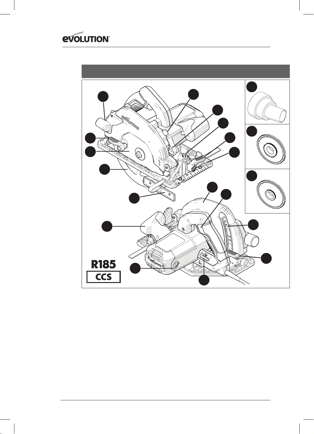
222
www.evolutionpowertools.com
USA
1. UTMATNINGSÖPPNING FÖR SÅGMATERIAL
2. TUMSPAK
3. TCT-BLAD FÖR FLERA MATERIAL
4. NEDRE BLADSKYDD
5. PARALLELL KANTSTYRARE
6. ERGONOMISKT FRAMHANDTAG
7. KOLBORSTAR
8. 5/16 TUM INSEXNYCKEL (BLADBYTE)
9. LÅSSPAK FÖR JUSTERING AV DJUP
10. DJUPSKALA
11. AV/PÅ-KNAPP FÖR BAKRE HANDTAG
12. ÖVRE BLADSKYDD
13. FINMEKANISK FOTPLATTA
14. TUMSPAK FÖR VINKELJUSTERING
15. GRADSKIVA-SKALA
16. LÅSKNAPP FÖR HJULAXEL
17. LED-LAMPA
18. DAMMUTSUGSKOPPLING
19. 25/32 TUM INNERBLADSFLÄNS
20. 5/8 TUM INNERBLADSFLÄNS
13
15
17
18
19
20
4
14
5
1
3
8
9
10
11
6
7
2
16
12
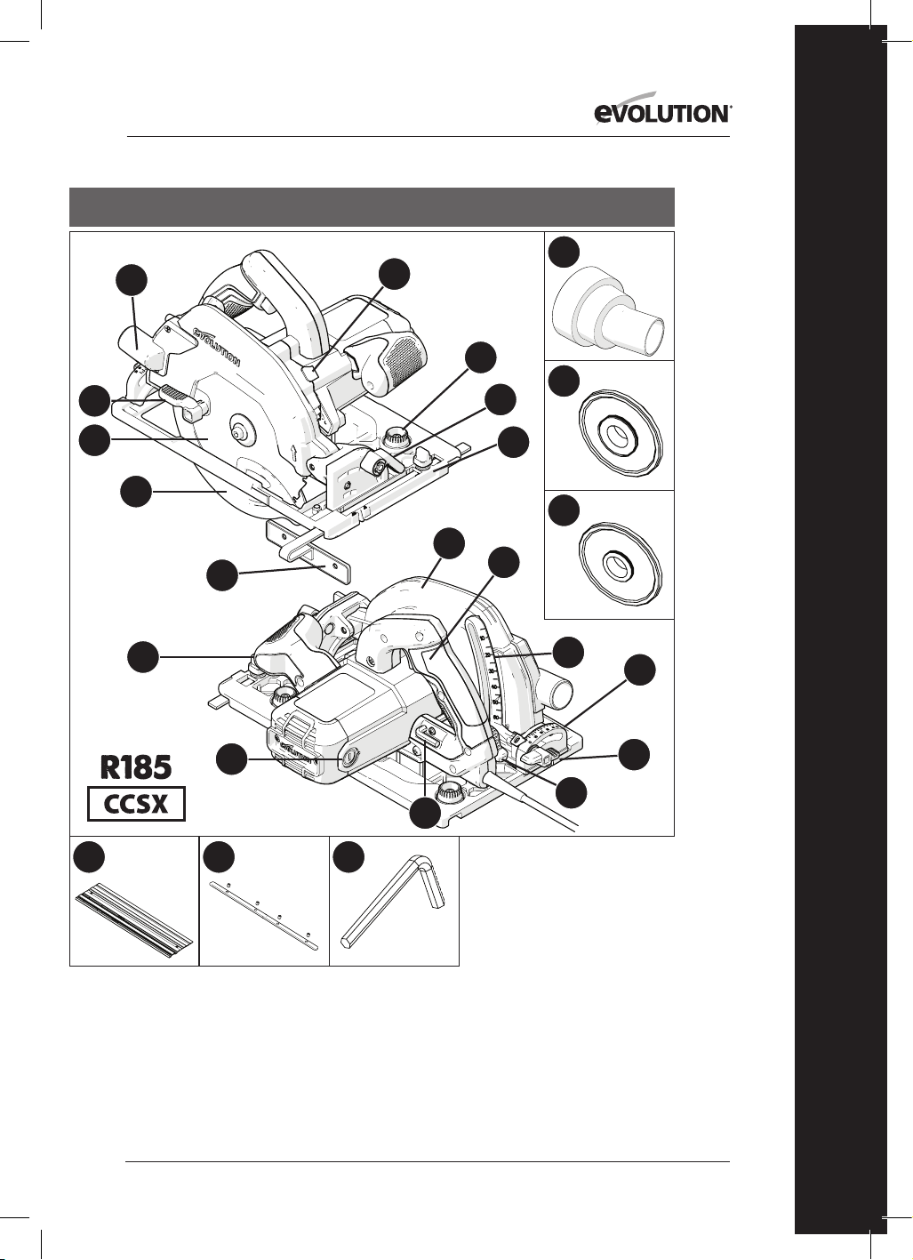
223
www.evolutionpowertools.com
SV
USA
1. UTMATNINGSÖPPNING FÖR
SÅGMATERIAL
2. TUMSPAK
3. TCT-BLAD FÖR FLERA MATERIAL
4. NEDRE BLADSKYDD
5. PARALLELL KANTSTYRARE
6. ERGONOMISKT FRAMHANDTAG
7. KOLBORSTAR
8. 5/16 TUM INSEXNYCKEL
(BLADBYTE)
9. SPAK FÖR JUSTERING AV DJUP
10. DJUPSKALA
11. AV/PÅ-KNAPP FÖR BAKRE
HANDTAG
12. ÖVRE BLADSKYDD
13. FINMEKANISK
SPÅRKOMPATIBEL FOTPLATTA
14. TUMSPAK
15. BAKRE GRADSKIVA-SKALA
16. LÅSKNAPP FÖR HJULAXEL
17. DAMMUTSUGSKOPPLING
18. 25/32 TUM INNERBLADSFLÄNS
19. 5/8 TUM INNERBLADSFLÄNS
20. VRIDKNAPPAR FÖR
SPÅRJUSTERING
21. TUMSKRUV FÖR BAKRE VINKEL
22. 3x 13–3/8 TUM SPÅR
23. 4x STÄNGER FÖR SPÅRFÄSTE
24. 1/8 TUM INSEXNYCKEL (SPÅR)
13
20
15
17
18
19
4
14
5
1
3
8
9
10
21
11
6
7
2
16
12
22 23 24

224
www.evolutionpowertools.com
USA
1. UTMATNINGSÖPPNING FÖR SÅGMATERIAL
2. TUMSPAK
3. TCT-BLAD FÖR FLERA MATERIAL
4. NEDRE BLADSKYDD
5. PARALLELL KANTSTYRARE
6. ERGONOMISKT FRAMHANDTAG
7. KOLBORSTAR
8. 8 MM INSEXNYCKEL (BLADBYTE)
9. LÅSSPAK FÖR JUSTERING AV DJUP
10. DJUPSKALA
11. AV/PÅ-KNAPP FÖR BAKRE HANDTAG
12. ÖVRE BLADSKYDD
13. FINMEKANISK SPÅRKOMPATIBEL
FOTPLATTA
14. TUMSPAK
15. BAKRE GRADSKIVA-SKALA
16. LÅSKNAPP FÖR HJULAXEL
17. LED-LAMPA
18. DAMMUTSUGSKOPPLING
19. 25/32 TUM INNERBLADSFLÄNS
20. 5/8 TUM INNERBLADSFLÄNS
21. VRIDKNAPPAR FÖR SPÅRJUSTERING
22. TUMSKRUV FÖR BAKRE VINKEL
13
21
15
17
18
19
20
4
14
5
1
3
8
9
10
22
11
6
7
2
16
12
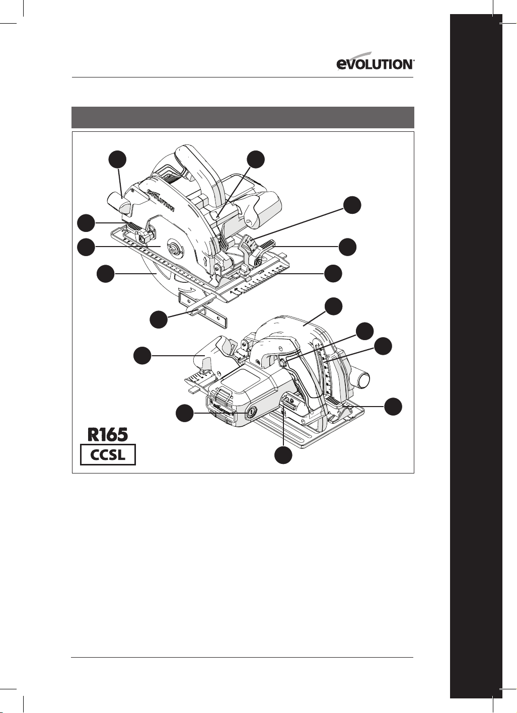
225
www.evolutionpowertools.com
SV
13
15
4
14
5
1
3
8
9
10
11
6
7
2
16
12
1. UTMATNINGSÖPPNING FÖR SÅGMATERIAL
2. TUMSPAK
3. TCT-BLAD FÖR FLERA MATERIAL
4. NEDRE BLADSKYDD
5. PARALLELL KANTSTYRARE
6. ERGONOMISKT FRAMHANDTAG
7. KOLBORSTAR
8. 8 MM INSEXNYCKEL (BLADBYTE)
9. LÅSSPAK FÖR JUSTERING AV DJUP
10. DJUPSKALA
11. BAKHANDTAG MED PÅ/AV
KNAPP FÖR SÄKERHETSSTART
12. ÖVRE BLADSKYDD
13. FINMEKANISK FOTPLATTA
14. TUMSPAK
15. GRADSKIVA-SKALA
16. LÅSKNAPP FÖR HJULAXEL
STORBRITANNIEN/EU/AUS
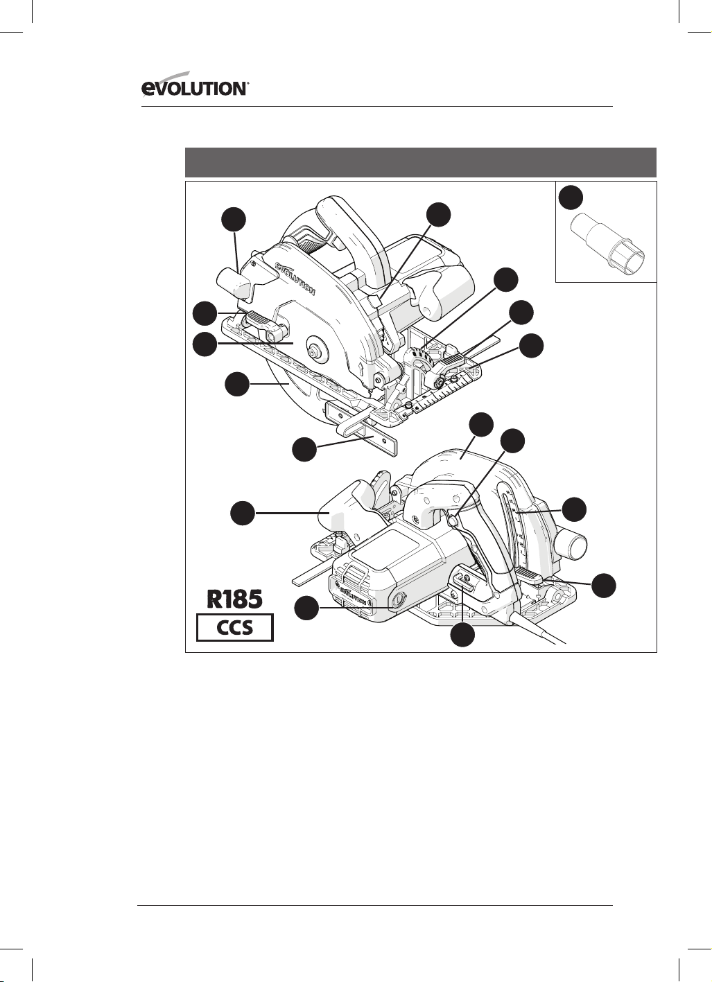
226
www.evolutionpowertools.com
1. UTMATNINGSÖPPNING FÖR SÅGMATERIAL
2. TUMSPAK
3. TCT-BLAD FÖR FLERA MATERIAL
4. NEDRE BLADSKYDD
5. PARALLELL KANTSTYRARE
6. ERGONOMISKT FRAMHANDTAG
7. KOLBORSTAR
8. 8 MM INSEXNYCKEL (BLADBYTE)
9. LÅSSPAK FÖR JUSTERING AV DJUP
10. DJUPSKALA
11. BAKHANDTAG MED PÅ/AV
KNAPP FÖR SÄKERHETSSTART
12. ÖVRE BLADSKYDD
13. FINMEKANISK FOTPLATTA
14. TUMSPAK
15. GRADSKIVA-SKALA
16. LÅSKNAPP FÖR HJULAXEL
17. DAMMUTSUGSKOPPLING
STORBRITANNIEN/EU
13
15
17
4
14
5
1
3
8
9
10
11
6
7
2
16
12
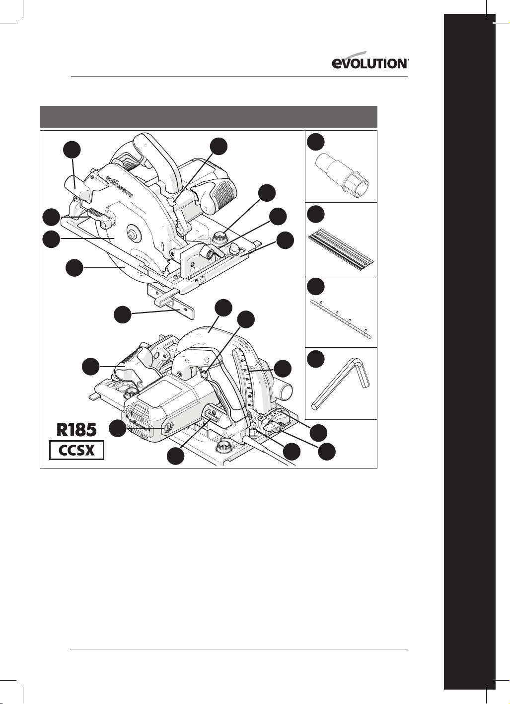
227
www.evolutionpowertools.com
SV
13
18
15
17
20
21
22
4
14
5
1
3
8
9
10
19
11
6
7
2
16
12
1. UTMATNINGSÖPPNING FÖR SÅGMATERIAL
2. TUMSPAK
3. TCT-BLAD FÖR FLERA MATERIAL
4. NEDRE BLADSKYDD
5. PARALLELL KANTSTYRARE
6. ERGONOMISKT FRAMHANDTAG
7. KOLBORSTAR
8. 8 MM INSEXNYCKEL (BLADBYTE)
9. LÅSSPAK FÖR JUSTERING AV DJUP
10. DJUPSKALA
11. BAKHANDTAG MED PÅ/AV
KNAPP FÖR SÄKERHETSSTART
12. ÖVRE BLADSKYDD
13. FINMEKANISK SPÅRKOMPATIBEL
FOTPLATTA
14. TUMSPAK
15. BAKRE GRADSKIVA-SKALA
16. LÅSKNAPP FÖR HJULAXEL
17. DAMMUTSUGSKOPPLING
18. VRIDKNAPPAR FÖR SPÅRJUSTERING
19. TUMSKRUV FÖR BAKRE VINKEL
20. 3x 340 mm SPÅR
21. 4x STÄNGER FÖR SPÅRFÄSTE
22. 3 mm INSEXNYCKEL
STORBRITANNIEN/EU

228
www.evolutionpowertools.com
STORBRITANNIEN/EU
1. UTMATNINGSÖPPNING FÖR SÅGMATERIAL
2. TUMSPAK
3. TCT-BLAD FÖR FLERA MATERIAL
4. NEDRE BLADSKYDD
5. PARALLELL KANTSTYRARE
6. ERGONOMISKT FRAMHANDTAG
7. KOLBORSTAR
8. 8 MM INSEXNYCKEL (BLADBYTE)
9. LÅSSPAK FÖR JUSTERING AV DJUP
10. DJUPSKALA
11. BAKHANDTAG MED PÅ/AV
KNAPP FÖR SÄKERHETSSTART
12. ÖVRE BLADSKYDD
13. FINMEKANISK SPÅRKOMPATIBEL
FOTPLATTA
14. TUMSPAK
15. BAKRE GRADSKIVA-SKALA
16. LÅSKNAPP FÖR HJULAXEL
17. DAMMUTSUGSKOPPLING
18. VRIDKNAPPAR FÖR SPÅRJUSTERING
19. TUMSKRUV FÖR BAKRE VINKEL
13
18
15
17
4
14
5
1
3
8
9
10
19
11
6
7
2
16
12

229
www.evolutionpowertools.com
SV
Fig. 3Fig. 2
Fig. 4
Fig. 1
Fig. 8
Fig. 6Fig. 5
Fig. 9
Fig. 10
Fig. 7a Fig. 7b Fig. 7c

230
www.evolutionpowertools.com
Fig. 11
Fig. 12
Fig. 13
Fig. 14
Fig. 15
Fig. 16
Fig. 17 Fig. 18
Fig. 21Fig. 20
Fig. 19
Fig. 22
1–2mm
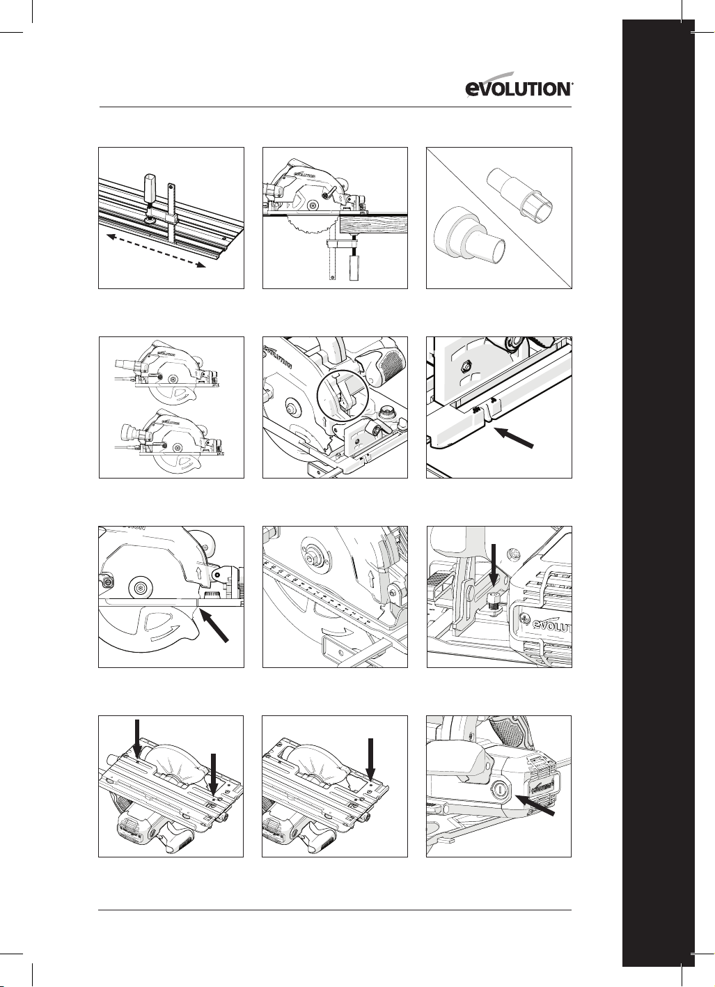
231
www.evolutionpowertools.com
SV
Fig. 27Fig. 26
Fig. 25
Fig. 30 Fig. 31
Fig. 34
Fig. 24Fig. 23
USAdammutsugningskoppling
EU-dammutsugningskoppling
Fig. 28
Fig. 29
Fig. 32 Fig. 33

232
www.evolutionpowertools.com
(10) FÖRBEREDELSE
VARNING: Koppla alltid ifrån maskinen från
elförsörjningen innan några justeringar görs.
Anmärkning: Dessa maskiner är utrustade med
en godkänd elkabel och kontakt för det land
de ska användas i. Modifiera eller ändra inte
elkabeln.
(10.1) MONTERING/
BORTTAGNING AV ETT BLAD
VARNING: Använd bara genuina Evolution-blad
(eller de som är godkända av Evolution Power
Tools), som är utformade för att användas i
dessa maskiner. Säkerställ att bladets högsta
hastighet är kompatibel med maskinen. Utför
endast arbetet när maskinen är bortkopplad
från elförsörjningen.
Anmärkning: Det rekommenderas att
operatören bär skyddshandskar vid hantering
av bladet vid montering eller när maskinbladet
byts ut.
• Leta upp den levererade insexnyckeln
för bladbyte som ligger i det monterade
förvaringsutrymmet (liknande position i alla
maskiner). (Fig. 1)
• Placera sågen på en jämn säker yta.
Anmärkning: Alla maskiner kan med omsorg
balanseras på en platt ände av motorhöljet,
(Fig. 2) vilket ger praktisk åtkomst till bladet och
bladfästen.
• Hitta maskinens hjulaxels låsknapp (som
finns på en liknande plats i alla maskiner). Lås
maskinens hjulaxel med hjulaxelns låsknapp.
(Fig. 3).
Anmärkning: Att rotera bladet långsamt
för hand, samtidigt som du försiktigt trycker
på hjulaxelns låsknapp kommer att hjälpa
hjulaxelns låsmanövrering.
• Använd insexnyckeln, lossa och ta bort
hjulaxelns sexkantsskruv, tillhörande fästen
och det yttre bladets drivfläns. (Fig. 4)
Anmärkning: Hjulaxelns sexkantsskruv har ett
standardskruvhuvud.
Vrid skruven medurs för att spänna den. Vrid
skruven moturs för att lossa den.
• Förvara den yttre bladflänsen och
tillhörande fästen på ett säkert vis.
• Rotera det lägre bladskyddet upp på det
övre bladskyddet med den manuella
tumspaken. (Fig. 5)
• Ta försiktigt bort bladet (om monterat) från
maskinen.
• Rengör de inre och yttre bladens drivflänsar
genomgående.
Anmärkning: Det inre bladets fläns kan
lämnas på plats om så önskas, men ska
kontrolleras och rengöras genomgående. Om
den tas bort från maskinen måste den sättas
tillbaka i samma riktning som den hade före
borttagning.
• Rengör bladet ordentligt runt det borrade
området (båda ytorna) där bladflänsen kan
komma i kontakt med och klämma bladet.
• Sätt in det (nya) bladet.
• Se till att riktningen på roteringspilarna som
är tryckta på bladet matchar riktningen på
roteringspilarna som finns på maskinens
övre och nedre bladskydd. (Fig. 6)
• Montera den yttre drivflänsen, hjulaxelns
sexkantsskruv och dess tillhörande fästen.
Anmärkning: Den yttre drivflänsen har
ett speciellt maskinbearbetat borrhål som
inkorporerar två "plana ytor", vilka är placerade
mitt emot varandra. (Fig. 7a) Dessa "plana
ytor" är ihopkopplade med två kompletterande
"plana ytor" som finns i maskinens hjulaxels
skaft.
• Sätt på hjulaxelns lock igen och spänn
hjulaxelns sexkantsskruv ordentligt med
insexnyckeln.
• Frigör hjulaxelns låsknapp
• Lägg tillbaka insexnyckeln på dess avsedda
förvaringsplats.
• Kontrollera att hjulaxelns lås har frigjorts
helt genom att manuellt rotera bladet.
• Kontrollera det nedre bladskyddets drift.
Anmärkning: Endast för den nordamerikanska
marknaden inkluderas en dubbelsidig
hjulaxelfläns, för 1 tum borrade blad (Fig. 7b)
och 5/8 tum borrade blad (Fig. 7c).
(11) PARALLELL KANTGUIDE
En parallell kantguide (Fig. 8) som kan vara
till speciell nytta vid klyvsågning, levereras
tillsammans med alla CCS-maskiner. Guiden
kan fästas till fotplattans framsida.
Guidens arm ska sättas in genom de
rektangulära skårorna som är belägna på en
av sidorna (framtill) av fotplattan i pressat stål,
och instuckna under den centralt belägna
justeringslåsskruven. (Fig. 9)

233
www.evolutionpowertools.com
SV
Anmärkning: Den parallella kantguiden kan
fästas på båda sidorna av fotplattan.
VARNING: Fäst och justera bara guiden
när maskinen är bortkopplad från
strömförsörjningen.
Anmärkning: Den parallella kantguidens arm
måste passera genom alla de rektangulära
skårorna som finns i fotplattan.
VARNING: Det kan vara farligt att montera
och försöka använda kantguiden när
armen passerar genom endast en (1) av de
maskinbearbetade rektangulära skårorna i
fotplattan.
Justera kantguiden så att den befinner sig
på önskad distans från bladet och spänn
justeringsskruven. Kontrollera att kantguiden
ligger parallellt mot sågbladet.
(12) JUSTERING AV SÅGDJUP
Anmärkning: Alla CCS-maskiner har samma
monteringar/fästen för djupjustering och
använder samma grundläggande teknik för att
ställa in bladdjup.
• Lossa låsmekanismen för djupjustering
genom att dra manöverspaken uppåt. (Fig.
10)
• Justera/ompositionera fotplattan för att få
önskat sågdjup (längden som bladet sticker
ut genom fotplattan).
Anmärkning: En djupskala finns på
djupjusteringskvadranten, med ett
motsvarande indexmärke inkorporerat i
maskinens angränsande övre bladskydd.
(Fig. 11) Att använda dessa funktioner kan
underlätta snabbinställning.
Anmärkning: Trots att djupskalan och
indexmärket är väldigt användbara och
möjliggör snabb djupinställning, ska de
endast ses som en guide till den uppnådda
inställningen.
Om ett väldigt precist sågdjup krävs, ska
bladinställningen kontrolleras med en
finmekanisk linjal (ingår inte) eller liknande och
justeras i enlighet.
• I de flesta fall ska sågdjupet ställas in till
tjockleken av materialet som ska sågas plus
djupet av en halv sågtand (tandens topp till
rot). (Fig.12)
• Spänn låsmekanismen för djupjustering
genom att trycka ner handtaget för att på
säkert vis låsa maskinen i önskad position.
(13) JUSTERING AV
SÅGVINKEL (AVFASNING)
Alla CCSL- och CCSX-maskiner har möjligheten
att luta bladet i (upp till) 45˚ och alla CCS-
maskiner har möjligheten att luta bladet i (upp
till) 60˚ åt vänster sida.
Därför är avfasningssågning möjlig.
Anmärkning: Bladet är i vertikalt läge när
gradskivan visar 0˚.
Anmärkning: En gradskiva (0˚–45˚ eller
0˚–60˚) är inkorporerad på avfasningslåsets
kvadrant som finns på fotplattans framsida.
Detta kommer att hjälpa till att göra en snabb
inställning av avfasningsvinkel men ska endast
ses som en guide.
Om en väldigt precis avfasningsvinkel krävs,
ska bladets inställning kontrolleras med ett
mätdon för vinkelmätning (ingår inte) och
justeras i enlighet.
• Lossa låsningsmekanismen för avfasning
som finns på maskinens framsida, genom
att dra spaken uppåt. (Fig. 13)
• Luta bladet till den önskade vinkeln i
enlighet med kvadrantens gradskiva. (Fig.
14)
• Spänn låsmekanismen för avfasning
ordentligt när den önskade
avfasningsvinkeln har uppnåtts genom att
trycka spaken neråt.
(14) RÅD GÄLLANDE DRIFT
(KONTROLLER FÖRE DRIFT)
Anmärkning: Då alla arbetsmiljöer kommer
att vara unika och skilja sig åt, erbjuder
Evolution Power Tools följande allmänna råd
gällande säkra arbetsprocesser och metoder
för operatören.
Dessa råd är inte uttömmande då Evolution
inte har någon inverkan på typen av verkstäder
eller arbetsmiljöer som dessa maskiner
används i.
Vi rekommenderar att operatören söker råd
från en behörig myndighet eller den ansvariga
handledaren för verkstaden om de känner sig
osäkra på hur dessa maskiner ska användas.
Det är viktigt att rutinmässiga
säkerhetskontroller utförs (vid varje
användningstillfälle) innan operatören

234
www.evolutionpowertools.com
använder maskinen.
VARNING: Säkerhetskontrollerna före
användning ska utföras när maskinen är
bortkopplad från elförsörjningen.
• Kontrollera att alla säkerhetsskydd fungerar
korrekt, och att alla justeringshandtag/
skruvar är ordentligt spända.
• Kontrollera att bladet är säkert och korrekt
monterat. Kontrollera också att bladet är
lämpligt för materialet som ska sågas.
• Kontrollera att elkabeln inte är trasig.
• Om det är möjligt, spänn fast arbetsstycket
på en stabil struktur som en arbetsbänk,
sågbock eller liknande.
• Operatören ska alltid vara medveten om
elkabelns position och riktning.
(15) PPE
• Operatören ska bära all relevant PPE
(Personlig skyddsutrustning) som är
nödvändig för uppgiften.
Detta kan vara skyddsglasögon, helmask,
dammfiltermask, säkerhetsskor osv.
Anmärkning: All CCS-seriemaskiner är
utrustade med en avfallsblåsare för såglinjen.
Denna dirigerar luft från en motordriven
fläkt mot området vid bladets framsida och
håller på så vis såglinjen relativt fri från skräp.
Den här funktionen kommer att förbättra
operatörens synfält och följa sågbladets
utveckling längs med skåran, samt hålla alla
ritningslinjer synliga.
VARNING: Allt damm som skapas kan vara
skadligt för hälsan.
En del material kan vara speciellt skadligt, och
operatören ska alltid bära en dammfiltermask
som är lämplig för materialet som arbetas med.
Professionell hjälp och rådgivning ska sökas
om operatören känner sig osäker på huruvida
materialet som ska sågas kan vara giftigt.
VARNING: Dessa maskiner ska aldrig
användas för att såga asbest eller annat
material som innehåller, eller som misstänks
innehålla asbest.
Konsultera/informera relevanta myndigheter,
och leta efter extra vägledning vid misstanke
om kontaminering av asbest.
(16) PÅ-/AV-STRÖMBRYTARE
Anmärkning: Alla maskiner för den
europeiska eller australienska marknaden är
utrustade med en säkerhetsstartavtryckare för
att förbättra operatörens säkerhet. (Fig.15)
För att starta motorn:
• Tryck in säkerhetslåsknappen på handtagets
sida med din tumme.
• Tryck ner strömbrytaren.
För att stoppa motorn:
• Släpp strömbrytaren.
VARNING: Motorn ska aldrig startas när
sågbladet är i direkt kontakt med någon av
arbetsstyckets ytor.
Anmärkning: Maskiner för den
nordamerikanska marknaden har en
PÅ-/AV-strömbrytare som inte har en
säkerhetsstartströmbrytare.
VARNING: Om sågen är "ledande" (LED-lampa
"PÅ"), undvik att oavsiktligt starta motorn
när maskinen lyfts upp från en arbetsbänk
eller liknande. Att oavsiktligt trycka ner PÅ-/
AV-strömbrytaren (belägen på handtaget) när
maskinen lyfts upp från viloläge kan leda till att
motorn startar.
SÅGSPÅR
Evolution CCSX-seriemaskiner (se
specifikationssidan för gällande modeller)
har utformats för att vara kompatibla med
sågspår.
Anmärkning: Alla cirkelsågar som kan
användas tillsammans med ett sågspår
kommer att ha en kanal längs med fotplattans
undersida (Fig. 16)
Maskiner från Evolution som är utrustade
på detta vis kan fästas till, och användas
tillsammans med de flesta sågspår (guider)
som för närvarande finns tillgängliga.
Anmärkning: Läs dokumentationen som
levererades tillsammans med spåret av
spårtillverkaren. Den tillhandahållna
dokumentationen kommer vanligtvis ge
monteringsinstruktioner för spåret, såväl som
information gällande säker arbetspraxis som
krävs när man använder utrustningen.
Sågspår kan användas när:
• En kap- eller cirkelsåg kan utgöra en hälso-
och säkerhetsrisk (H&S) eller vid andra
praktiska arbetsplatsproblem. Exempelvis,

235
www.evolutionpowertools.com
SV
när man arbetar på en plats där mycket
frekventa och noggranna kontroller kan
vara nödvändiga, (arbete på ett tak eller på
en byggnadsställning osv.) kan ett sågspår
ge användaren extra (och säkra) operativa
möjligheter.
• Exakta snitt över eller längs med långa
arbetsstycken krävs. Exempelvis på ramar,
dörrar, stora brädor eller väggpaneler osv,
kan sågspår/guide eliminera behovet att
använda cirkelsåg i frihandsläge.
Anmärkning: Evolutions maskiner som är
kompatibla med sågspår har två (2) kammar
som sträcker sig in i fotplattans kanal (en i varje
ände).
Vridknappar (Fig. 17) gör det möjligt för
operatören att rotera dessa kammar.
Reducering av dessa kammar kommer att
minska den effektiva bredden av fotplattans
kanal en aning.
Detta kan vara nödvändigt för att tillgodose
eventuella små variationer i spårbredd, som
kan uppstå vid tillverkning av spårextrudering.
Spårbredd som skapats av olika tillverkare kan
också variera en aning.
Anmärkning: Operatören ska justera dessa
kammar så att maskinen enkelt och lätt kan
flyttas framåt eller bakåt när den är korrekt
placerad på ett spår utan att det finns någon
lateral rörelse (vinglar).
EVOLUTIONS SÅGSPÅR
En del av Evolutions maskiner (beroende på
modell och destinationsmarknad) levereras
tillsammans med ett sågspår.
Anmärkning: Evolutions sågspår finns
tillgängliga som inköpsalternativ för kunden.
Kontakta din leverantör eller Evolution Power
Tools för mer information.
SPÅRET
Evolutions spårsystem har två (2) eller tre (3)
precisionsextruderade metallsektioner.
(Fig. 18) Dessa sektioner måste kopplas ihop
med de levererade stängerna. (Fig. 19)
För att sätta ihop sektionerna (Fig. 19):
• Sätt stängerna på t-spåren som finns på
undersidan av extruderingarna.
• Se till att (ungefär) lika stor del av stängerna
sätts in i sektionerna så att de kan kopplas
samman.
• Spänn de sexkantiga ställskruvarna för att
sätta ihop sektionerna.
Anmärkning: Det är viktigt att ett litet
avstånd, mellan 1 och 2 mm, lämnas mellan de
sammanfogade sektionerna.
Detta kommer att garantera att en cirkelsåg
som placeras på och används tillsammans med
en tvärgående räls från Evolution kommer att
glida lätt längs med hela spårets längd.
GENOMFÖRANDE AV SÅG-TILL-
SPÅR
Anmärkning: Följande riktlinjer gäller
Evolutions cirkelsågar och Evolutions
sågspår. Läs informationen som levererades
tillsammans med sågen och/eller från
sågspårets tillverkare om den använda
cirkelsågen eller sågspåret inte kommer från
Evolution.
Innan första användning av Evolutions sågspår
måste splinterskyddsremsan (Fig. 21) matcha
sågen och bladet.
För att matcha sågen med bladet:
• Montera sågspåret i dess helhet.
• Läs avsnittet med titeln "Spårjustering
och fastspänning". Spänn fast spåret till en
lämplig del av reserv- eller restmaterial.
• Ställ in sågbladet på ett lämpligt djup för
det valda restmaterialet.
• Se till att det inte finns något som blockerar
bladets väg underifrån.
• Läs avsnittet med titeln "Spårjustering och
fastspänning". Placera cirkelsågen korrekt
på spåret.
• Starta motorn och låt den nå full hastighet.
• Tryck cirkelsågen lätt och långsamt längs
med hela spåret fram tills bladet har sågat
igenom hela splinterskyddsremsans längd.
Anmärkning: Den här processen kommer
matcha en specifik såg med ett specifikt spår.
Om en annan såg används på ett förberett
spår, kan splinterskyddsremsan inte ge samma
skydd som den dedikerade såg-till-spår-
konfigurationen.
Anmärkning: Splinterskyddsremsan ska
betraktas som en förbrukningsartikel. Den
kommer att slitas ut och nötas med tiden och
kommer därför behöva ersättas. Den kan också

236
www.evolutionpowertools.com
behöva ersättas om en annan cirkelsåg eller
sågblad (med en annan sågbredd) än den
ursprungliga dedikerade konfigurationen ska
användas.
UTBYTBAR
SPLINTERSKYDDSREMSA
Då detta är en förbrukningsartikel ska den
utbytbara splinterskyddsremsan kontrolleras
med regelbundna intervall för skada eller
nötning som uppkommit vid slitage. Ersätt
remsan om skada eller signifikant slitage
upptäcks.
Ersättningsremsor finns tillgängliga. Kontakta
din leverantör eller Evolution på lämplig
hjälplinje.
Den levererade splinterskyddsremsan är ett
direkt substitut för originalet. Dra enkelt bort
den gamla remsan från spåret och sätt i den
nya remsan.
Anmärkning: Om en ny remsa monteras måste
såg-till-spår-matchningsprocessen upprepas.
EVOLUTIONS SPÅR-KLÄMMOR
(SÄLJS SEPARAT)
Evolutions hastighetsklämma (Fig. 22) är
specialkonstruerad för att fungera tillsammans
med Evolutions sågspår.
Anmärkning: Extra klämmor kan köpas
från Evolution Power Tools eller din lokala
leverantör.
Evolutions klämmor passar på och kan glida
längs med de t-formade spåren som finns på
aluminiumextruderingen. (Fig. 23)
Detta gör det möjligt för operatören att placera
klämmorna (en krävs i varje ände av spåret),
vilket ger maximal säkerhet och stabilitet för
sågspåret till arbetsstycket.
SPÅRJUSTERING OCH
FASTSPÄNNING
Anmärkning: Följande riktlinjer är rådgivande.
Evolution har ingen inverkan på vilka
arbetsmiljöer eller under vilka förhållanden
som utrustningen används.
VARNING: Om utrustningen ska användas på
en byggarbetsplats, ska operatören konsultera
relevant person som ansvarar för hälsa och
säkerhet gällande ytterligare säkerhetskrav och
instruktioner för platsen.
• Markera tydligt arbetsstycket och speciellt
såglinjen längs med vilken sågbladet ska
flytta sig.
• Montera sågspåret med så många sektioner
som krävs för att spänna fast arbetsstycket,
inklusive hänsynstagande till överhäng.
• Använd Evolutions hastighetsklämmor (det
bästa alternativet) eller lämpliga G-formade
klämmor. Placera spåret på arbetsstycket och
säkra det genom att spänna klämmorna.
• Se till att splinterskyddsremsans kant löper
exakt längs med den markerade såglinjen.
VARNING: Såglinjen måste hänga över
arbetsstycket vid den inledande kanten. (Fig.
24)
Det lägre bladskyddet måste dras tillbaka
manuellt och svängas uppåt på det övre
bladskyddet när cirkelsågen placeras på spåret.
VARNING: Bladet är exponerat i det här läget.
Tryck INTE ner avtryckaren förrän följande
säkerhetskontroller har gjorts.
GÖR ETT SNITT
Att göra ett snitt med sågspåret är nästan som
att göra ett vanligt snitt med en cirkelsåg. Alla
säkerhetsprocesser och protokoll som gäller
vid användning av cirkelsåg kommer även att
gälla när en sådan såg används tillsammans
med ett tvärgående sågspår.
Följande riktlinjer, även om de inte är
heltäckande, ger några allmänna råd:
• Utför säkerhetskontroller för att se till att
sågspåret är säkrat till arbetsstycket, samt
att arbetsstycket är säkrat och inte rör sig
vid sågning.
• Se till att det inte finns något som blockerar
under arbetsstycket, då detta skulle kunna
förhindra sågbladets väg eller förstöras av
sågbladet.
• Se till att elkabeln är riktad på ett sådant
sätt att den inte utgör en snubbelrisk
(eller liknande). Kontrollera speciellt att
elkabeln inte kommer i kontakt med sågens
roterande blad.
• Operatören ska ha ett bra fotfäste, balans
och total kontroll hela tiden som sågen
används på spåret. Speciell försiktighet ska
utövas när bladet tas bort från arbetsstycket.
VARNING: Speciellt vid arbete på höjd (andra
omständigheter kan också gälla), se till att
inte något sågmaterial kan falla ned och
skadar personer i närheten. Operatören kan
behöva överväga hur man kan samla ihop eller

237
www.evolutionpowertools.com
SV
fånga sådant sågmaterial. Rådfråga personen
som ansvarar för platssäkerhet för specifik
vägledning.
Anmärkning: Operatören bör utföra
en testomgång med sågen när den är
bortkopplad från elförsörjningen för att
garantera att sågarbetet kommer att vara helt
säkert.
När snittet har slutförts ska operatören släppa
PÅ-/AV-strömbrytaren och låta motorn stanna
helt och låta bladet bli stationärt.
När sågen lyfts upp från sågspåret och
arbetsstycket kommer det lägre bladskyddet
automatiskt att täcka bladet helt.
INSAMLING AV DAMM/SKRÄP
Ett adaptormunstycke (Fig. 25) kan sättas
fast på alla CCS-maskiner. När munstycket
används kan maskinen anslutas till en damm-/
skräpinsamlingsenhet.
Anmärkning: Den exakta designen på
munstycket som levereras kommer att variera
beroende på maskinens modelltyp och
destinationsmarknad.
Det levererade munstycket kommer att
kunna användas med flera olika damm-/
skräpinsamlingsenheter som finns tillgängliga.
Munstycket kan fästas till utmatningsporten
för sågat material. (Fig. 26)
Anmärkning: En verkstadsutsugningsmaskin
för damm/skräp kan fästas till
adaptormunstycket vid behov. Följ
tillverkarens instruktioner om en sådan maskin
används och se till att den kan hantera det
utmatade sågmaterialet.
LED-LAMPA
En del av dessa maskiner (beroende på
modellen och destinationsmarknaden) är
utrustade med en automatisk LED-lampa.
Anmärkning: Om du är osäker på
vilka funktioner din maskin har, läs
specifikationssidan som finns i den här
manualen.
LED-lampan finns på vänster sida om bladet.
(Fig. 27)
Strålen från LED-lampan kommer att lysa på
vänster sida av bladet och också lysa upp
eventuella markerade linjer som finns på
arbetsstycket. Detta kan hjälpa operatören att
förutse bladets väg genom arbetsstycket och
på så vis hjälpa till att göra det mer effektivt,
noggrant och säkert.
Anmärkning: LED-lamporna fungerar
automatiskt. Så fort maskinen är ansluten till
elförsörjningen kommer LED att aktiveras.
Det här ger operatören en tydlig visuell
indikation att maskinen har anslutits till
strömförsörjningen, och därmed är påslagen
(är strömförande) och redo att börja användas.
Anmärkning: Det finns inga delar
inkorporerade tillsammans med LED-ljuset
som kan underhållas av användaren och
strålens riktning är fabriksinställd. Linsskyddet
ska hållas fritt från damm osv. (se underhåll) för
att garantera att maximal ljusstyrka från den
projicerade strålen upprätthålls.
VARNING: Rengör endast linsskyddet
när maskinen är bortkopplad från
strömförsörjningen och bladet är helt
stationärt.
INTEGRERADE SÅGHJÄLPMEDEL
Alla Evolutions cirkelsågar är utrustade med
flera såghjälpmedel eller guider som är
utformade för att hjälpa operatören att göra
snabba korrekta snitt på säkert vis.
Anmärkning: Följande funktioner finns inte på
alla maskiner.
0˚ och 45˚ linje för sågguider (Fig. 28)
Belägna på den främre kanten av maskinens
fotplatta finns två (2) små skåror, som på en del
maskiner identifieras med en vinkelsiffra. Dessa
skåror indikerar bladets läge när det tar sig ur
arbetsstycket när lutningsvinkeln är inställd på
0˚ (vertikalt blad) eller vid en vinkel på 45˚.
Bladguidens framsida (Fig. 29)
Anmärkning: Evolutions maskiner som är
kompatibla med Evolutions sågspår har en
skåra belägen på fotplattans högra kant.
Denna skåra indikerar läget för bladets
framkant när bladet är inställt på maximalt
sågdjup. Den här funktionen kan användas vid
placering och positionering av sågen i dess
sågspår.
VARNING: Det är viktigt att det lägre
bladskyddet eller bladet inte rör vid någon
av arbetstyckets ytor under den ursprungliga
positioneringen av sågen på sågspåret.
Linjalguider (Fig. 30)
Linjalguider finns på några av Evolutions

238
www.evolutionpowertools.com
cirkelsågar. De finns längs med fotplattans
framsida och/eller sidkanter.
Dessa guider kan ge användbar ungefärlig
position för sågbladet i arbetsstycket.
SPECIALJUSTERINGAR
Din Evolution-maskin har många finmekaniska
komponenter och inställningar, de flesta är
fabriksinställda och justerade för att garantera
beständig långsiktig precision.
Underhåll och justering av dessa komponenter
eller inställningar kommer troligtvis aldrig
att behövas. Om underhåll eller justering
(efter mycket användning) kan tänkas vara
nödvändig rekommenderar Evolution att
du kontaktar den tekniska hjälplinjen för
ytterligare råd och vägledning.
Anmärkning: En del justeringar är
endast möjliga om man har åtkomst till
expertkunskap och/eller utrustning.
(17) ALLMÄNNA RÅD VID
SÅGNING
VARNING: Operatören måste alltid vara
medveten om elkabelns position och riktning.
Kabeln måste riktas på sådant vis att det inte
nns någon risk att bladet kommer i kontakt
med elkabeln.
Kabeln ska inte utgöra en snubblingsrisk (eller
annan typ) för operatören eller andra personer
i närheten.
• Överbelasta inte maskinen.
• Låt sågbladet göra arbetet. Sågning ska
inte utföras med överdrivet tryck mot
maskinen, för då kommer bladets livslängd
att förkortas.
• När parallell kantguide används, se till att
den är parallell med bladet. Bladet och/eller
motorn kan skadas om maskinen används
tillsammans med en felaktigt justerad
parallell kantguide.
• Placera framkanten på fotplattan rakt på
arbetsstycket. Före motorn startas, se till att
bladet inte är i kontakt med arbetsstycket.
• När sågning påbörjas, se till att introducera
bladet i materialet långsamt, så att inga av
bladets tänder förstörs.
Anmärkning: Två (2) linjer med sågguider
tillhandahålls på fotplattans framsida för
CCSL-maskinen (endast för 0˚ och 45˚
avfasningsvinklar).
• Använd båda händerna för att förytta
sågen framåt genom arbetsstycket.
• Applicera ett lätt konstant tryck för att ytta
sågen framåt genom arbetsstycket.
Anmärkning: Alla CCS-seriemaskiner har
ett automatiskt lägre bladskydd som har
en specialformad främre framkant. Den här
funktionen garanterar att bladskyddet dras
tillbaka smidigt och utan ansträngning när
maskinens blad tränger ner i arbetstycket. När
bladet tas bort från arbetsstycket kommer det
lägre bladskyddet automatiskt att återgå till sin
normala position och täcka bladet helt.
Anmärkning: Vid en del tillfällen, exempelvis
vid en dyksågning i ett golv eller en vägg osv.
kan det vara fördelaktigt att dra tillbaka det
lägre bladskyddet manuellt.
En tumspak tillhandahålls på det lägre
bladskyddet. En utbildad operatör kan
försiktigt dra tillbaka bladskyddet manuellt,
antingen delvist eller helt, och på så vis
möjliggöra dyksågningar.
VARNING: Om bladskyddet dras tillbaka
manuellt måste stor försiktighet vidtas för att
se till att operatörens hand eller ngrar inte rör
vid någon av maskinens blad.
När sågning har slutförts:
• Släpp PÅ-/AV-avtryckaren.
• Låt bladet stanna helt.
• Ta bort maskinen från arbetsstycket och
låt bladskyddet återvända till sin normala
position och täcka bladet helt.
VARNING: Om motor stannar eller fastnar
under sågning, släpp strömbrytaren direkt.
Koppla bort maskinen från strömförsörjningen
och ta bort maskinen från arbetsstycket.
Kontrollera orsaken till problemet och
korrigera om möjligt.
Försöka bara starta om motorn om du är helt
säker på att det är säkert att göra det.
UTMATNINGSÖPPNING FÖR
SÅGMATERIAL
VARNING: Använd inte dammpåsen eller
dammportadaptor när metalliskt material,
inklusive trä med spikar sågas.
(18) UNDERHÅLL OCH JUSTERINGAR
Läget 0˚ (vertikalt blad) kan justeras.
VARNING: Maskinen måste kopplas bort från
strömförsörjningen när den här processen
påbörjas.

239
www.evolutionpowertools.com
SV
För att kontrollera läget 0˚:
• Ställ in bladet på 0˚ med
lutningsmekanismen mot dess stopp.
• Kontrollera bladet mot fotplattan med en
anslagsvinkel (ingår inte). Var försiktig och
undvik tändernas TCT-spetsar. Bladet ska
vara exakt 90˚ mot fotplattan.
Anmärkning: Det lägre bladskyddet ska
roteras (manuellt) upp in på det övre
bladskyddet. Det kommer att ge en mer
korrekt positionering av anslagsvinkeln och på
så vis hjälpa till vid kontrollprocessen.
Om justering krävs:
R165CCSL och 185CCS
Vrid justeringsskruven (Fig. 31) medurs eller
moturs med en 4 mm insexnyckel (ingår inte)
fram tills bladet är exakt 90˚ mot fotplattan.
R185CCSX och 185CCSX+
Vrid justeringsskruvarna (Fig. 32) medurs eller
moturs med en 3mm insexnyckel (ingår inte)
fram tills bladet är exakt 90˚ mot fotplattan.
För att kontrollera läge 45˚ (R185CCSX och
185CCSX+):
• Ställ in bladet på 45˚ med
lutningsmekanismen mot dess stopp.
• Kontrollera bladet mot fotplattan med en
anslagsvinkel (ingår inte). Var försiktig och
undvik tändernas TCT-spetsar. Bladet ska
vara exakt 45˚ mot fotplattan.
Vrid justeringsskruvarna (Fig. 33) medurs eller
moturs med en 3mm insexnyckel (ingår inte)
fram tills bladet är exakt 45˚ mot fotplattan.
(19) KONTROLL OCH BYTE
AV KOLBORSTAR
VARNING: Koppla bort maskinen från
strömförsörjningen innan kontroll eller byte av
kolborstar.
Anmärkning: Ersätt båda kolborstarna om
någon av dem har mindre än en längd på
6mm kol kvar, eller om fjädern eller tråden är
förstörd eller bränd.
För att ta bort borstarna:
• Skruva av plastlocken som finns på
motorhöljets baksida. (Fig. 34) Var försiktig,
locken är fjäderbelastade.
• Ta bort borstarna och fjädrarna.
• Om byte krävs, förnya borstarna och ersätt
locken.
Anmärkning: Begagnade men användbara
borstar kan ersättas men bara så länge de
placeras i samma position och
sätts in på samma sätt som de var innan de
togs bort från maskinen.
• Låt maskinens motor gå utan vikt under
ungefär 5 minuter. Detta kommer att hjälpa
de nya borstarna att bäddas in och se till att
motorn fungerar effektivt.
• En del gnistor kan finnas fram tills borstarna
har bäddats in helt.
(20) ALLMÄNT UNDERHÅLL
OCH RENGÖRING
Anmärkning: Allt underhåll ska utföras när
maskinen är avstängd och bortkopplad från
strömförsörjningen.
• Kontrollera regelbundet att alla
säkerhetsfunktioner och skydd fungerar
korrekt. Använd endast maskinen om alla
skydd/säkerhetsfunktioner fungerar korrekt.
• Alla motorlager i dessa maskiner är smorda
för maskinens livslängd. Ingen ytterligare
smörjning krävs.
Använd en ren, lätt fuktad trasa för att rengöra
maskinens delar. Använd inte lösningsmedel
eller liknande produkter som kan skada
plastdelarna.
Ta bort allt damm eller annan kontamination
från linsskyddet för LED-modulen.
VARNING: Försök inte rengöra genom att
sätta in spetsiga föremål i maskinhöljets
öppningar osv. Maskinens luftventiler ska
rengöras med komprimerad torrluft.
Anmärkning: Operatören ska använda all
nödvändig PPE när komprimerad torr luft
används som rengöringsmetod.
(21) MILJÖSKYDD
Avfall från elektriska produkter ska inte slängas
tillsammans med hushållsavfall. Återvinn
vid anläggningar. Kontakta dina lokala
myndigheter eller återförsäljare för råd om
återvinning.
240
www.evolutionpowertools.com
EG-FÖRSÄKRAN OM ÖVERENSSTÄMMELSE
Tillverkaren av produkten som täcks av den här deklarationen är:
Storbritannien: Evolution Power Tools Ltd, Venture One, Longacre Close, Holbrook Industrial Estate,
Sheeld, S20 3FR.
Franska: Evolution Power Tools SAS, 61 Avenue Lafontaine, 33560, Carbon-Blanc, Bordeaux, Frankrike.
Tillverkaren försäkrar härmed att maskinen i enlighet med deklarationen uppfyller alla de relevanta
bestämmelserna för maskindirektivet och andra lämpliga direktiv som detaljeras nedan.
Tillverkaren försäkrar vidare att maskinen som detaljeras i den här deklarationen, där tillämpligt,
uppfyller relevanta bestämmelser för viktiga hälso- och säkerhetskrav.
Direktiven som täcks av den här deklarationen detaljeras nedan:
Och är förenliga med gällande krav i följande dokument:
EN IEC 55014-1:2021 • EN IEC 55014-2:2021 • EN IEC 61000-3-2:2019/A1:2021 •
EN 62841-1:2015/A11:2022 • EN62841-2-5:2014 • EN 55014-1:2017+A11:2020 • EN 55014-2:2015 •
EN 61000-3-2: 2014 (220–240V modeller)• EN IEC 61000-3-2:2019 (220–240V modeller) •
EN 61000-3-3:2013+A1:2019 (endast 026-0001) •
EN IEC 61000-3-11:2019 (220–240V modeller förutom 026-0001)
Produktdetaljer
Beskrivning: R165CCSL 165mm (6–1/2 tum) Cirkelsåg
Modellnr: 026-0001/026-0002/026-0003
Beskrivning: R185CCS 185mm (7–1/4 tum) Cirkelsåg
Modellnr: 027-0001C / 027-0002C / 027-0003C
Beskrivning: R185CCSX 185mm (7–1/4 tum) Cirkelsåg
Modellnr: 027-0001/027-0002/027-0003
Beskrivning: R185CCSX+ 185mm (7–1/4 tum) Cirkelsåg
Modellnr: 027-0001A/027-0003A/027-0003A
Varumärkesnamn: EVOLUTION POWER TOOLS LIMITED
Spänning: 220–240V/110V ~ 50Hz
Inmatning: R165CCSL - 1200W
R185CCS, R185CCSX och R185CCSX+ - 1600W
Den tekniska dokumentationen som krävs för att visa att produkten uppfyller kraven i direktivet har
sammanställts och finns tillgänglig för inspektion av relevant tillsynsmyndighet, och bekräftar att vår
tekniska dokumentation innehåller de dokument som listas ovan
och att de har de korrekta standarderna för produkten som detaljeras ovan.
Namn och adress för innehavare av teknisk dokumentation.
Undertecknad: Utskrift: Barry Bloomer
Chef för distributionskedja och upphandling
Datum: 21/02/2023
Storbritannien: Evolution Power Tools Ltd, Venture One, Longacre Close, Holbrook Industrial Estate,
Sheeld, S20 3FR.
Franska: Evolution Power Tools SAS, 61 Avenue Lafontaine, 33560, Carbon-Blanc, Bordeaux, Frankrike.
1907/2006 Registrering, utvärdering, auktorisering och begränsning av kemikalier och REACH EC Nr. 1907/2006
bilaga XVII
2006/42/EC. Maskindirektiv.
2014/30/EU. Direktivet om elektromagnetisk kompatibilitet.
2011/65/EU.
och
2015/863/EU.
Direktivet om begränsad användning av vissa farliga substanser i elektronisk utrustning (RoHS).
2012/19/EU. Direktivet om el och elektronikavfall (WEEE).

241
www.evolutionpowertools.com
SV

242
www.evolutionpowertools.com
(1.2) INTRODUCERE
AVERTISMENT:
Vă rugăm să citiți cu atenție și integral aceste instrucțiuni
de operare și siguranță.
Pentru siguranța dumneavoastră, dacă aveți nelămuriri cu
privire la orice aspect al folosirii acestui echipament, vă
rugăm să apelați centrul de suport tehnic corespunzător,
al cărui număr de telefon poate fi găsit pe site-ul web
Evolution Power Tools. În cadrul organizației noastre, la
nivel global, avem deschise mai multe centre de asistență
telefonică, dar serviciul de asistență tehnică este oferit și
de furnizorul dumneavoastră.
(1.3) DATE DE CONTACT:
Site Web: www.evolutionpowertools.com
UK/EU/AUS: customer[email protected]
USA: evolutioninfo@evolutionpowertools.com
(1.4) GARANȚIE
Felicitări pentru achiziția unui aparat Evolution Power
Tools. Vă rugăm să efectuați înregistrarea on-line a
produsului, conform instrucțiunilor din broșura de
înregistrare, oferită împreună cu acest aparat. Astfel,
introducându-vă datele, perioada de garanție a aparatului
dumneavoastră va fi validată prin intermediul site-ului
web Evolution și veți beneficia de service prompt, în caz
de nevoie.
Vă mulțumim sincer pentru că ați ales
un produs al Evolution Power Tools.
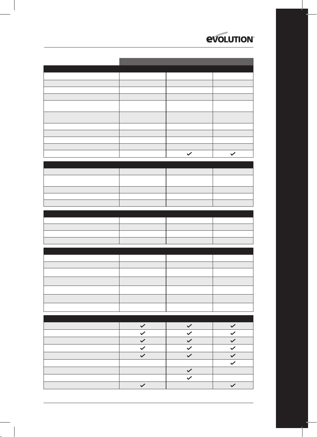
243
www.evolutionpowertools.com
RO
USA
SPECIFICAȚII UNEALTĂ
R185CCS R185CCSX R185CCSX+
Model nr.: 027-0004 027-0004C 027-0004A
Motor UE (220-240 V ~ 50 Hz)
Motor Marea Britanie (110 V ~ 50 Hz)
Motor SUA (120V ~ 60 Hz) 15A 15A 15A
Viteza de încărcare (220-240 v) 3700 min-1/
rpm
Viteza de încărcare (110 și 120 v) 3700
min-1/rpm
3700 min
-1
/ rpm 3700 min
-1
/ rpm 3700 min
-1
/ rpm
Greutate 10.8 lb 11.2 lb 11.2 lb
Unghi maxim de înclinare a discului (grade) 60˚ 45˚ 45˚
Lungime cablu de alimentare 3,96 m (13 ft) 13 ft 13 ft
Tip bază fierăstrău circular Aluminiu turnat Aluminiu turnat Aluminiu turnat
Compatibil cu șină de tăiere
CAPACITĂȚI DE TĂIERE R185CCS R185CCSX R185CCSX+
Placă de oțel moale (grosime maximă) 1/4” 1/4” 1/4”
Cheson de oțel moale (grosime maximă a
peretelui)
1/4” 1/4” 1/4”
Grosime maximă de tăiere (0°) (cu șină) 2-1/2” 2-1/2” (2-5/16” cu șină) 2-1/2” (2-5/16” cu șină)
Grosime maximă de tăiere (45°) 1-9/16” 1-13/16” (1-5/8” cu șină) 1-13/16” (1-5/8” cu șină)
Grosime maximă de tăiere (60°) 1”
SPECIFICAȚII DISC R185CCS R185CCSX R185CCSX+
Diametru disc Ø 7-1/4” Ø 7-1/4” Ø 7-1/4”
Număr de dinți 20 16 20
Alezaj 25/32” 25/32” 25/32”
Tăietură 1.7mm 1.7mm 1.7mm
DATE NIVEL DE ZGOMOT ȘI VIBRAȚIE R185CCS R185CCSX R185CCSX+
Nivel presiune acustică L
pa
97,3dB(A) K=3 dB(A) 97,3dB(A) K=3 dB(A) 97,3dB(A) K=3 dB(A)
Nivel presiune acustică L
wa
105,3dB(A) K=3 dB(A) 105,3dB(A) K=3 dB(A) 105,3dB(A) K=3 dB(A)
Vibrație - mâner principal (tăiere lemn)
A
h,w
= 3,347m/s
2
a
h,w
= 3,347m/s
2
a
h,w
= 3,347m/s
2
Vibrație - mâner auxiliar (tăiere lemn)
A
h,w
= 3,119m/s
2
a
h,w
= 3,119m/s
2
a
h,w
= 3,119m/s
2
Vibrație - mâner principal (tăiere metal)
a
h,M
= 3,572m/s
2
a
h,M
= 3,572m/s
2
a
h,M
= 3,572m/s
2
Vibrație - mâner auxiliar (tăiere metal)
a
h,M
= 3,241m/s
2
a
h,M
= 3,241m/s
2
a
h,M
= 3,241m/s
2
Factor K nesiguranță
1,5m/s
2
1,5m/s
2
1,5m/s
2
ARTICOLE FURNIZATE R185CCS R185CCSX R185CCSX+
Disc TCT multimaterial
Cheie impus (pentru schimbarea discului)
Ghidaj margini paralele
Adaptor fantă de praf
Conector furtun de praf
Casetă de transport
Șină de tăiere - 340 mm (13-3/8”) x 3
Bară de conectare și șuruburi (x 4)
Bec cu LED
SPECIFICAȚII

244
www.evolutionpowertools.com
UK / EU / AUS
R165CCSL R185CCS R185CCSX R185CCSX+
026-0001 / 026-0002 /
026-0003
027-0001C /
027-0002C / 027-0003C
027-0001 /
027-0002 / 027-0003
027-0001A /
027-0002A / 027-0003A
1200W 1600W 1600W 1600W
1200W 1600W 1600W 1600W
3700 min
-1
/ rpm 3900 min
-1
/ rpm 3900 min
-1
/ rpm 3900 min
-1
/ rpm
3700 min
-1
/ rpm 3700 min
-1
/ rpm 3700 min
-1
/ rpm 3700 min
-1
/ rpm
4.3 kg 4.9 kg 5.1 kg 5.1 kg
45˚ 60˚ 45˚ 45˚
3m 3m 3m 4m
Oțel presat Aluminiu turnat Aluminiu turnat Aluminiu turnat
R165CCSL R185CCS R185CCSX R185CCSX+
3mm 6mm 3mm 6mm
3mm 6mm 3mm 6mm
53mm 64mm 64mm (59mm cu șină) 64mm (59mm cu șină)
34mm 40mm 47mm (42mm cu șină) 47mm (42mm cu șină)
24mm
R165CCSL R185CCS R185CCSX R185CCSX+
Ø 165mm Ø 185mm Ø 185mm Ø 185mm
14 20 16 20
20mm 20mm 20mm 20mm
1.7mm 1.7mm 1.7mm 1.7mm
R165CCSL R185CCS R185CCSX R185CCSX+
92,4dB(A) K:3dB(A) 97,3dB(A) K=3 dB(A) 97,3dB(A) K=3 dB(A) 97,3dB(A) K=3 dB(A)
103,4dB(A) K:3dB(A) 105,3dB(A) K=3 dB(A) 105,3dB(A) K=3 dB(A) 105,3dB(A) K=3 dB(A)
a
h,w
= 2,747m/s
2
a
h,w
= 3,347m/s
2
a
h,w
= 3,347m/s
2
a
h,w
= 3,347m/s
2
a
h,w
= 2,619m/s
2
a
h,w
= 3,119m/s
2
a
h,w
= 3,119m/s
2
a
h,w
= 3,119m/s
2
a
h,M
= 2,302m/s
2
a
h,M
= 3,572m/s
2
a
h,M
= 3,572m/s
2
a
h,M
= 3,572m/s
2
a
h,M
= 2,239m/s
2
a
h,M
= 3,241m/s
2
a
h,M
= 3,241m/s
2
a
h,M
= 3,241m/s
2
1,5m/s
2
1,5m/s
2
1,5m/s
2
1,5m/s
2
R165CCSL R185CCS R185CCSX R185CCSX+
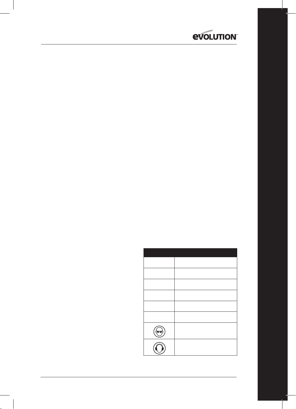
245
www.evolutionpowertools.com
RO
VIBRAȚIE
(1.5) Notă: Măsurarea vibrației a fost efectuată
în condiții standard conform cu:
EN 62841-1: 2015, EN 62841-2-5: 2014
Avertisment: Purtați protecție pentru
urechi!
Valoarea totală a vibrației declarate a fost
măsurată în conformitate cu o metodă
standard de testare și poate fi folosită pentru
compararea unei unelte cu alta.
Valoarea totală a vibrației declarate poate fi
folosită, de asemenea, la evaluarea preliminară
a expunerii.
(1.6) AVERTISMENT: La folosirea acestei
unelte, operatorul poate fi expus la niveluri
ridicate de vibrație transmisă la nivelul mâinii
și al brațului.
Este posibil ca operatorul să dezvolte
„afecțiunea degetelor albe” (sindromul
Raynaud). Această afecțiune poate să reducă
sensibilitatea mâinii la temperatură, precum și
să ducă la o stare generală de amorțire.
Persoanele care utilizează această unealtă în
mod regulat sau pentru perioade mai lungi de
timp trebuie să țină sub control atent starea
mâinilor și a degetelor. În cazul în care apar
simptome clare, solicitați imediat un consult
medical.
• Măsurarea și evaluarea gradului de expunere
a utilizatorului la vibrațiile transmise la
nivelul mâinii la locul de muncă sunt
detaliate în: EN 62841-1 și EN 62841-2-5
• Mulți factori pot influența nivelul efectiv al
vibrațiilor în timpul operării, de exemplu,
starea și orientarea suprafeței de lucru,
precum și tipul și starea uneltei folosite.
Înaintea fiecărei întrebuințări, aceste
aspecte trebuie verificate și, acolo unde este
necesar, trebuie aplicate practicile de muncă
corespunzătoare. Gestionarea acestor factori
poate ajuta la reducerea efectelor vibrațiilor:
Manevrarea
• Manevrați unealta cu grijă,
lăsând aparatul să acționeze.
• Evitați să aplicați forță fizică în exces asupra
oricăror comenzi ale uneltei.
• Țineți cont de siguranța și stabilitatea
dumneavoastră,
precum și de orientarea uneltei în timpul
utilizării.
Suprafața de lucru
• Țineți cont de materialul suprafeței de lucru;
de starea, densitatea, rezistența,
rigiditatea și orientarea acestuia.
AVERTISMENT: Vibrațiile emise în timpul
utilizării propriu-zise a uneltei pot fi diferite de
valoarea totală declarată, în funcție de modul
în care unealta este folosită.
Necesitatea de a identifica măsuri de siguranță
și de a proteja operatorul se bazează pe o
estimare a expunerii în condiții de muncă
efectivă (ținând cont de toate etapele ciclului
de operare, cum ar fi timpii când unealta este
oprită, când funcționează în gol, pe lângă
timpul de funcționare efectivă).
(1.7 )
ETICHETE ȘI SIMBOLURI
AVERTISMENT: Nu operați această unealtă
dacă etichetele de avertizare și/sau instruire
lipsesc sau sunt deteriorate. Contactați
Evolution Power Tools pentru înlocuirea
etichetelor.
Notă: Toate sau unele dintre următoarele
simboluri pot să apară în manual sau pe
produs.
(1.8)
Simbol Descriere
V
Volți
A
Amperi
Hz
Hertzi
Min
-1
/ RPM
Viteză
~
Curent alternativ
n
o
Turație la mers în gol
Purtați ochelari de protecție
Purtați protecție pentru urechi
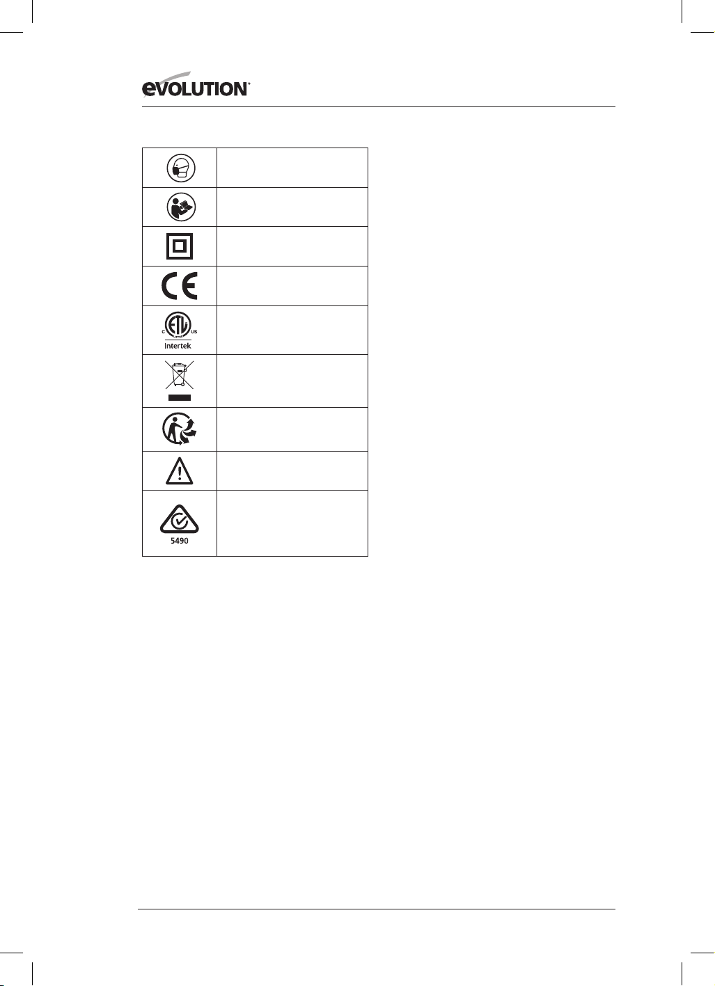
246
www.evolutionpowertools.com
Purtați protecție împotriva
prafului
Citiți instrucțiunile
Dublu izolat
Certicare CE
Certicare CSA
Deșeuri electrice și
echipamente electronice
Triman - Colectare și reciclare
deșeuri
Avertisment
(RCM) Marca respectării
reglementărilor
pentru echipamente electrice și
electronice. Standard australian/
neozeelandez
(1.9) IÎNTREBUINȚARE PREVĂZUTĂ
PENTRU ACEASTĂ UNEALTĂ
ELECTRICĂ
AVERTISMENT: Acest produs este un
fierăstrău circular cu acționare manuală și a
fost proiectat pentru a fi utilizat cu discurile
speciale Evolution. Folosiți numai accesorii
proiectate pentru utilizare cu această unealtă
și/sau cu cele special recomandate de
Evolution Power Tools Ltd.
Când este prevăzută cu un disc adecvat,
această unealtă poate fi folosită pentru a tăia:
Oțel moale
Aluminiu
Lemn
Notă: Tăierea oțelului galvanizat poate reduce
durata de viață a discului.
(1.10)
ÎNTREBUINȚARE INTERZISĂ
PENTRU ACEASTĂ UNEALTĂ
ELECTRICĂ
AVERTISMENT: Acest produs este un
fierăstrău circular cu acționare manuală și
trebuie folosit strict în acest sens. Nu trebuie
modificat în niciun fel și nu trebuie folosit
pentru a alimenta orice alt echipament
sau a acționa orice alte accesorii, în afara
celor menționate în prezentul Manual de
instrucțiuni.
(1.11) AVERTISMENT: (1.11) AVERTISMENT:
Această unealtă nu este destinată a fi utilizată
de persoane (inclusiv copii) cu capacități
fizice, senzoriale sau mentale reduse sau
de persoane cărora le lipsesc experiența și
cunoștințele, decât dacă au fost supravegheate
sau instruite cu privire la utilizarea în siguranță
a uneltei de către o persoană răspunzătoare
pentru siguranța lor și care este competentă în
utilizarea sigură a acesteia.
Copiii trebuie supravegheați pentru a nu avea
acces la această unealtă și nu au voie să se
joace cu ea.
(1.12)
SIGURANȚĂ LA CURENT
ELECTRIC
Această unealtă este prevăzută cu ștecăr
turnat și conectori la rețea corespunzători
pieței de destinație. În cazul în care cablul
de alimentare prezintă urme de deteriorare,
trebuie înlocuit cu un cablu sau ansamblu
special, disponibil de la fabricant sau de la
agentul său de service.
(1.13)
UTILIZARE LA EXTERIOR
AVERTISMENT: Pentru protecția
dumneavoastră, în cazul în care această
unealtă este folosită în exterior, nu trebuie să
fie expusă la condiţii de ploaie și nici folosită în
locuri umede. Nu așezați unealta pe suprafețe
umede. Folosiți un banc de lucru curat și uscat,
dacă este posibil. Pentru mai multă protecție,
folosiți un dispozitiv de curent rezidual (D.C.R.)
care întrerupe alimentarea cu electricitate
atunci când scurgerea de curent în pământ
depășește 30 mA pentru 30 ms. Verificați
întotdeauna funcționarea dispozitivului
de curent rezidual (D.C.R.) înainte de
întrebuințarea uneltei.
Dacă este necesar un cablu prelungitor, acesta
trebuie să fie de tipul potrivit pentru utilizare
în exterior și să fie etichetat astfel.
Trebuie respectate instrucțiunile fabricantului
atunci când folosiți un cablu prelungitor.
(2.1)
INSTRUCȚIUNI GENERALE DE
SIGURANȚĂ
(Aceste instrucțiuni generale de siguranță

247
www.evolutionpowertools.com
RO
pentru unelte electrice sunt conforme cu
specificațiile BS EN 60745-1:2009,
EN 61029-1:2009 și EN 62847-1:2015).
AVERTISMENT: Citiţi toate avertismentele
de siguranță și instrucțiunile de folosire.
Nerespectarea avertismentelor
și instrucțiunilor poate provoca șocuri
electrice, incendii și/sau vătămări grave.
Păstrați toate avertismentele și instrucțiunile
pentru referințe ulterioare. Termenul „unealtă
electrică” din avertismente se referă la
unealta dumneavoastră electrică cu acționare
manuală (cu cablu) sau la unealta electrică cu
acumulator (fără cablu).
(2.2)
1) Avertismente generale de siguranță
pentru unelte electrice [Siguranța zonei de
lucru]
a) Păstrați zona de lucru curată și bine
iluminată. O zonă de lucru aglomerată și
întunecoasă predispune la accidente.
b) Nu operați unelte electrice în atmosfere
explozive, cum ar fi în prezența lichidelor
inflamabile, a gazelor sau a pulberii.
Uneltele electrice scot scântei care pot aprinde
pulberea sau aburii.
c) Țineți copiii și privitorii la distanţă atunci
când operați o unealtă electrică. Orice vă
distrage atenția vă poate face să pierdeți
controlul.
(2.3)
2) Avertismente generale de siguranță
pentru unelte electrice
[Siguranța la
curentul electric]
a) Ștecărele uneltelor electrice trebuie
să se potrivească cu priza. Nu modificați
niciodată ștecărul în niciun fel. Nu folosiți
ștecăre adaptoare la uneltele electrice cu
împământare. Ștecărele nemodificate și prizele
pe măsură reduc riscul de electrocutare.
b) Evitați contactul fizic cu suprafețele
împământate, cum ar fi țevile, caloriferele,
plitele și frigiderele. Există un risc sporit
de electroșoc în cazul în care corpul
dumneavoastră face circuit cu solul.
c) Nu expuneți uneltele electrice la ploaie
sau la condiții de umezeală. Pătrunderea
apei într-o unealtă electrică crește riscul de
electroșoc.
d) Nu forțați cablul. Nu folosiți niciodată
cablul pentru a transporta, a trage sau
scoate din priză unealta electrică. Țineți
cablul departe de căldură, ulei, muchii ascuțite
și piese mobile. Cablurile deteriorate sau
încâlcite cresc riscul de electroșoc.
e) Atunci când operați o unealtă electrică
la exterior, folosiți un cablu prelungitor
potrivit pentru utilizare la exterior. Folosirea
unui cablu potrivit pentru utilizare la exterior
reduce riscul de electroșoc.
f) În cazul în care operarea unei unelte
electrice într-un loc umed este inevitabilă,
folosiți o sursă de alimentare protejată cu
un dispozitiv de curent rezidual (DCR).
Utilizarea unui DCR reduce riscul de
electroșoc.
Notă: Produsul este destinat utilizării numai în
spații cu o capacitate a curentului de serviciu
≥100 A pe fază, alimentată de la o rețea de
distribuție cu o tensiune nominală de 230
V. Dacă este necesar, contactați compania
furnizoare de electricitate pentru a vă
asigura că capacitatea electrică la punctul de
conectare la rețeaua publică de alimentare
este adecvată pentru conectarea produsului.
(2.4)
3) Avertismente generale de siguranță
pentru unelte electrice
[Siguranța
personală]
a) Fiți vigilent, atent la ce faceți și dați
dovadă de simț practic atunci când operați
o unealtă electrică. Nu folosiți unealta
electrică când sunteți obosit sau sub influența
drogurilor, alcoolului sau medicamentelor. O
singură clipă de neatenție când operați unelte
electrice poate avea ca rezultat vătămări
personale grave.
b) Folosiți echipament personal de
protecție Purtați întotdeauna protecție
pentru ochi. Echipamentul de protecție,
cum ar fi măștile anti-praf, încălțămintea de
siguranță antialunecare, casca sau protecția
pentru urechi, folosit în condiții adecvate, va
reduce posibilitatea producerii de vătămări
corporale.
c) Preveniți pornirea accidentală. Asigurați-
vă că butonul de pornire este în poziția
oprit înainte de a conecta unealta la sursa
de curent și/sau la acumulator, înainte de
a o ridica sau transporta. Transportarea
uneltelor electrice cu degetul pe comutator
sau alimentarea cu curent a uneltelor electrice
care au comutatorul pornit predispune la
accidente.
d) Îndepărtați cheia de reglare de butucul
discului înainte de a porni unealta electrică.
O cheie rămasă atașată la o piesă rotativă
a uneltei electrice poate duce la vătămări
corporale.
e) Nu vă întindeți. Mențineți-vă tot timpul
echilibrul și o poziție stabilă. Astfel veți

248
www.evolutionpowertools.com
controla mai bine unealta electrică în situații
imprevizibile.
f) Îmbrăcați-vă corespunzător. Nu purtați
haine largi sau bijuterii. Țineți-vă părul,
hainele sau mănușile la distanţă de piesele
mobile. Hainele largi, bijuteriile sau părul lung
se pot prinde în piesele mobile.
g) Dacă sunt furnizate dispozitive pentru
conectarea pieselor de extracție și colectare
a prafului, asigurați-vă că acestea sunt
conectate și folosite în mod adecvat.
Utilizarea colectorului de praf poate reduce
riscurile asociate prafului.
h) Nu lăsați ca obișnuința cu alte unelte
folosite frecvent să vă facă să neglijați
sau să ignorați principiile de siguranță ale
uneltei. O acțiune neglijentă poate provoca
vătămări grave într-o fracțiune de secundă.
(2.5)
4) Avertismente generale de siguranță
pentru uneltele electrice
[Utilizarea și
întreţinerea uneltei electrice].
a) Nu forțați unealta electrică. Folosiți
unealta electrică adecvată nevoilor
dumneavoastră. Unealta electrică adecvată
va face treaba mai bine și mai sigur într-un
ritm pentru care a fost proiectată.
b) Nu folosiți unealta electrică dacă nu
se pornește și oprește de la buton. Orice
unealtă electrică ce nu poate fi controlată de la
comutator este periculoasă și trebuie reparată.
c) Deconectați unealta electrică de la
sursa de curent înaintea de a efectua orice
reglaje, înainte de a schimba accesorii sau
înainte de a o depozita. Aceste măsuri de
siguranță preventive reduc riscul de pornire
accidentală a uneltei electrice.
d) Nu depozitați uneltele electrice
la îndemâna copiilor și nu permiteți
persoanelor nefamiliarizate cu unealta
electrică sau cu aceste instrucțiuni să
opereze unealta electrică. Uneltele electrice
sunt periculoase dacă ajuns în mâna unor
utilizatori neinstruiți.
e) Întreținerea uneltelor electrice. Asigurați-
vă că nu există nealinieri sau blocaje ale
pieselor mobile, fisuri ale pieselor mobile
sau orice alt defect care ar putea afecta
funcționarea uneltei electrice. Dacă este
defectă, solicitați repararea uneltei electrice
înainte de utilizare. Multe accidente sunt
provocate de întreținerea deficitară a uneltelor
electrice.
f) Păstrați instrumentele de tăiat ascuțite și
curate. Uneltele electrice întreținute adecvat
cu muchiile ascuțite bine nu agață și sunt mai
ușor de controlat.
g) Folosiți unealta electrică, accesoriile,
piesele detașabile ale acesteia etc. în
conformitate cu aceste instrucțiuni,
ținând cont de condițiile de lucru și de
lucrul ce urmează a fi efectuat. Utilizarea
uneltei electrice pentru alte operații decât
cele prevăzute poate conduce la situații
periculoase.
h) Păstrați mânerele și suprafețele de
prindere uscate, curate și fără urme de
ulei și grăsime. Mânerele și suprafețele de
prindere alunecoase nu permit manevrarea
și controlul sigur al uneltei în situații
imprevizibile.
(2.6)
5) Avertismente generale de siguranță
pentru uneltele electrice
[Service]
a) Solicitați depanarea uneltei
dumneavoastră electrice de către un
depanator calificat, folosind numai piese
de schimb identice. Acest lucru va garanta
menţinerea gradului de siguranţă a uneltei
electrice.
(2.7)
RECOMANDĂRI PRIVIND
SĂNĂTATEA
AVERTISMENT: Atunci când folosiți unealta,
se pot produce particule de praf. În unele
situații, în funcție de materialele cu care
lucrați, acest praf poate fi deosebit de
dăunător. Dacă bănuiți că vopseaua de pe
suprafața materialului pe care doriți să îl tăiați
conține plumb, cereți sfatul unui profesionist.
Vopselele pe bază de plumb trebuie
îndepărtate numai de către un profesionist
și este recomandabil să nu încercați să o
îndepărtați singur.
Odată ce praful s-a depus pe suprafețe,
contactul mâinii cu gura poate duce la
ingerarea plumbului. Expunerea chiar și la
niveluri reduse de plumb poate influența
ireversibil sistemul nervos și creierul. Deosebit
de vulnerabili sunt copiii mici si copiii nenăscuți.
Este recomandat să aveți în vedere riscurile
asociate materialelor cu care lucrați și să
reduceți riscul de expunere.
Întrucât unele materiale pot produce praf
care poate fi periculos pentru sănătatea
dumneavoastră, vă recomandăm să folosiți
măști pentru față aprobate, cu filtre înlocuibile,
atunci când folosiți această unealtă.
Trebuie întotdeauna:
• Să lucrați într-o zonă bine ventilată.
• Să lucrați cu echipament de siguranță

249
www.evolutionpowertools.com
RO
aprobat, cum ar fi măștile de praf, care
sunt proiectate special să filtreze particule
microscopice.
(2.8) AVERTISMENT: operarea uneltelor
electrice poate face ca obiecte străine să fie
aruncare spre ochii dumneavoastră, ceea ce
poate provoca leziuni grave. Înainte de a începe
să folosiți unealta electrică, purtați întotdeauna
ochelari de protecție cu scut lateral sau scut
complet pentru față, atunci când e necesar.
INSTRUCȚIUNI DE SIGURANȚĂ
PENTRU TOATE FIERĂSTRAIELE
[Proceduri de tăiere]
a) PERICOL: Țineți mâinile departe de zona de
tăiere și de disc. Țineți cealaltă mână pe mânerul
auxiliar sau pe carcasa motorului. Dacă ambele
mâini țin fierăstrăul, nu pot fi tăiate de disc.
b) Nu duceți mâna sub piesa de lucru. Scutul
nu vă poate proteja de disc, sub piesa de lucru.
c) Reglați adâncimea tăierii la grosimea
piesei de lucru. Sub piesa de lucru trebuie să fie
vizibil mai puțin de un dinte întreg al discului.
d) Nu țineți niciodată piesa de lucru în mâini
sau peste picior atunci când o tăiați. Prindeți
piesa de lucru pe o platformă stabilă. Este
important să susțineți piesa bine pentru a
minimiza expunerea corpului, blocarea discului
sau pierderea controlului.
e) Țineți Unelte electrice de suprafețele
de prindere izolate, atunci când efectuați
o operație în timpul căreia instrumentul
de tăiere poate intra în contact cu cabluri
ascunse sau cu propriul cablu. Contactul cu
cabluri electrificate va electrifica, de asemenea,
piesele de metal expuse ale uneltei electrice, iar
operatorul poate suferi un electroșoc.
f) Când efectuați operații de despicare,
folosiți întotdeauna un separator de
despicare sau un ghidaj drept pentru
margine. Astfel crește precizia la tăiere și scad
șansele ca discul să se blocheze.
g) Folosiți întotdeauna discuri cu orificii pe
guler de dimensiunea și forma corecte (romb
vs rotund). Discurile care nu se potrivesc cu
piesa de montare a fierăstrăului se vor descentra,
ducând la pierderea controlului.
h) Nu folosiți niciodată șaibe de disc sau
șurub deteriorate sau necorespunzătoare.
Șaibele de disc și șurubul au fost proiectate
special pentru fierăstrăul dumneavoastră, pentru
performanță optimă și operare în siguranță.
(3.2)[Cauze recul și avertismente conexe]
Reculul este reacția bruscă la ciupirea, blocarea
sau nealinierea discului fierăstrăului, care face ca
fierăstrăul scăpat de sub control să se ridice și să
iasă din piesa de lucru către operator;
Atunci când discul este ciupit sau blocat strâns
în tăietura care se închide, discul se oprește, iar
reacția motorului proiectează rapid aparatul
înapoi spre operator;
În cazul în care discul se răsucește sau iese din
aliniere cu tăietura, dinții de pe muchia din spate
a discului se pot înfige în partea de sus a lemnului,
făcând discul să iasă din tăietură și să sară către
operator.
(3.3) Reculul rezultă în urma utilizării incorecte
și/sau a procedurilor ori condițiilor incorecte
de utilizare și poate fi evitat luând măsurile de
precauție adecvate, așa cum se arată mai jos.
a)
Mențineți o priză fermă, cu ambele
mâini, pe fierăstrău și poziționați-vă
brațele pentru a vă împotrivi forței de
recul. Poziționați-vă corpul de o parte a
discului, dar nu în linie cu discul.
Reculul
poate face ca fierăstrăul să sară în spate, însă forța
de recul poate fi controlată de operator, dacă sunt
luate măsurile de precauție adecvate.
b) Atunci când discul se blochează sau când
întrerupeți tăierea din orice motiv, eliberați
comutatorul și țineți discul nemișcat în
material până când discul se oprește
complet.
Nu încercați niciodată să îndepărtați
fierăstrăul de piesă sau să îl trageți în spate în timp
ce discul este în mișcare, altfel se poate produce
recul. Investigați și luați măsuri corective pentru a
elimina cauza blocării discului.
c) Când reporniți fierăstrăul într-o piesă
de lucru, centrați discul fierăstrăului în
tăietură astfel încât dinții de tăiere să nu
atingă materialul.
În cazul în care discul se
blochează, acesta poate ieși în sus sau poate fi
împins în spate din piesa de lucru atunci când
fierăstrăul este repornit.
d) Nu folosiți discuri boante sau deteriorate.
Discurile neascuțite sau montate necorespunzător
produc tăieturi înguste, care cauzează fricţiune
excesivă, blocarea discului și recul.
e) Manetele de blocare a adâncimii discului
și reglării înclinării trebuie să fie strânse
bine înainte de a face o tăietură.
Dacă reglajul
discului suferă modificări în timpul tăierii, se poate
produce blocarea discului și recul.
f) Manetele de blocare a adâncimii discului
și reglării înclinării trebuie să fie strânse
bine înainte de a face o tăietură.
Dacă
reglajul discului suferă modificări în timpul tăierii,
se poate produce blocarea discului și recul.
g) Fiți extrem de precauți când decupați în
ziduri sau în alte zone oarbe.
Discul ieșit în
afară poate tăia obiecte care pot produce recul.

250
www.evolutionpowertools.com
FUNCȚIONAREA SCUTULUI
INFERIOR
a)Verificați ca scutul inferior să fie bine
închis înaintea fiecărei utilizări. Nu operați
fierăstrăul dacă scutul inferior nu se mișcă
liber și nu se închide imediat.
Nu prindeți
niciodată cu clemă și nu legați scutul inferior
în poziție deschisă. Dacă fierăstrăul este scăpat
accidental, scutul inferior se poate îndoi. Ridicați
scutul inferior cu mânerul retractabil și asigurați-vă
că se mișcă liber și că nu atinge discul sau orice
altă parte, în toate unghiurile și adâncimile de
tăiere.
b) Verificați funcționarea arcului scutului
inferior. În cazul în care scutul și arcul
nu funcționează corect, acestea trebuie
reparate înainte de utilizare.
Scutul inferior
poate funcționa greu din cauza pieselor
deteriorate, a depunerilor lipicioase sau a
acumulărilor de impurități.
c) Scutul inferior poate fi retras manual
doar pentru tăieturi speciale, cum ar fi
„tăieturile în adâncime” și „tăieturile
compuse”.
Ridicați scutul inferior de la mânerul
retractabil și, imediat ce discul pătrunde în
material, scutul inferior trebuie să fie eliberat.
Pentru orice altă operațiune de tăiere, scutul
inferior trebuie să funcționeze automat.
d) Aveți întotdeauna grijă ca scutul
inferior să acopere discul înainte de a pune
fierăstrăul pe banc sau pe podea.
Un disc
neprotejat și în mișcare va face ca fierăstrăul să se
deplaseze spre înapoi, tăind tot ce întâlnește în
cale. Atenție la timpul necesar opririi discului după
ce comutatorul este eliberat.
INSTRUCȚIUNI DE SIGURANȚĂ
SUPLIMENTARE PENTRU
FIERĂSTRAIELE CIRCULARE
a) Nu folosiți discuri de fierăstrău
de tipul „oțel rapid” (high speed steel - HSS)
b) Inspectați unealta și discul înaintea fiecărei
utilizări. Nu folosiți discuri deformate, crăpate,
roase sau cu alte deteriorări.
c) Nu folosiți niciodată fierăstrăul fără
sistemul original de protecție cu scut. Nu
blocați scutul mobil în poziția deschis. Asigurați-vă
că scutul operează liber fără a se bloca.
d) Folosiți doar discuri care au caracteristicile
specificate în acest manual. Înainte de a folosi
accesorii, comparați întotdeauna RPM maxim
permisă a accesoriului cu RPM a uneltei.
e) Nu folosiți discuri abrazive.
f) Folosiți doar discuri de diametru/diametre
conforme cu marcajele.
(3.4) AVERTISMENT: În cazul în care lipsește o
piesă, nu operați unealta până când piesa lipsă
nu este înlocuită. Nerespectarea acestei reguli
poate avea ca rezultat vătămarea corporală.
(4.1)
PRIMII PAȘI - DESPACHETAREA
Caution:
Această cutie conține obiecte
ascuțite. Aveți grijă când despachetați.
Scoateți din cutie unealta, împreună cu
accesoriilor furnizate. Verificați cu atenție
ca unealta să fie într-o stare bună și faceți
inventarul tuturor accesoriilor enumerate în
acest manual. De asemenea, asigurați-vă că
toate accesoriile sunt complete.
Dacă descoperiți că lipsesc piese, unealta și
accesoriile sale trebuie returnate împreună în
ambalajul original către vânzător.
Nu aruncați ambalajul; păstrați-l la loc sigur pe
toată perioada de garanție. Eliminați ambalajul
într-un mod ecologic. Reciclați, dacă este
posibil. Nu lăsați copiii să se joace cu pungile
de plastic goale. Există risc de sufocare.
(4.3) MANUALE DE INSTRUCȚIUNI
EVOLUTION
Evolution Power Tools livrează fiecare produs
cu un Manual de instrucțiuni.
Fiecare manual specific este alcătuit și gândit
cu atenție pentru a oferi informații ușor
accesibile și utile cu privire la utilizarea în
siguranță, îngrijirea și întreținerea produsului.
Consultând informațiile din manual,
operatorul va putea să exploateze în siguranță
întregul potențial al uneltei.
Politica Evolution privind dezvoltarea
continuă a produselor poate însemna că,
foarte rar, conținutul unui manual anume
poate să nu reflecte complet ultimele
îmbunătățiri sau actualizări ce au fost
aduse unui produs anume. Actualizările/
îmbunătățirile specificațiilor unui produs pot
surveni ca urmare a avansului tehnologic
sau a modificării cadrului legislativ al țării de
destinație etc.
Dacă aveți nelămuriri cu privire la orice aspect
legat de utilizarea, îngrijirea și întreținerea
unui produs Evolution, contactați centrul
relevant de asistență Evolution, unde veți
primi informații actualizate și recomandări
suplimentare.
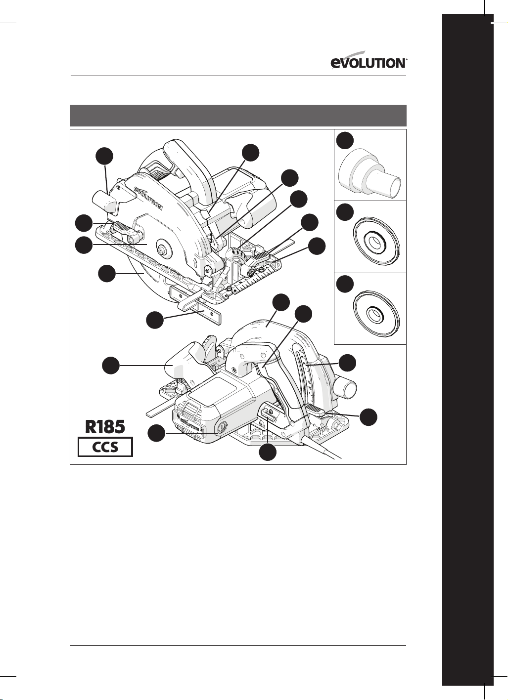
251
www.evolutionpowertools.com
RO
USA
1. FANTĂ DE ELIMINARE MATERIAL TĂIAT
2. CLAPETĂ
3. DISC TCT MULTIMATERIAL
4. SCUT INFERIOR DE DISC
5. GHIDAJ MARGINI PARALELE
6. MÂNER ERGONOMIC FRONTAL
7. PERII CU CĂRBUNE
8. CHEIE IMBUS (PENTRU SCHIMBAREA
DISCULUI)
9. CLAPETĂ DE BLOCARE A ADÂNCIMII
REGLATE
10. ȘUBLER DE ADÂNCIME
11. MÂNER POSTERIOR CU BUTON DE OPRIRE/
PORNIRE DE SIGURANȚĂ
12. SCUT SUPERIOR DE DISC
13. PLACĂ DE BAZĂ GRADATĂ
14. CLAPETĂ
15. ECHER
16. BUTON BLOCARE ARBORE
17. BECUL LED
18. CONECTOR FANTĂ DE PRAF
19. FLANȘĂ DISC INTERN DE 25/32’’
20. FLANȘĂ DISC INTERN DE 5/8’’
13
15
17
18
19
20
4
14
5
1
3
8
9
10
11
6
7
2
16
12

252
www.evolutionpowertools.com
USA
1. FANTĂ DE ELIMINARE MATERIAL
TĂIAT
2. CLAPETĂ
3. DISC TCT MULTIMATERIAL
4. SCUT INFERIOR DE DISC
5. GHIDAJ MARGINI PARALELE
6. MÂNER ERGONOMIC FRONTAL
7. PERII CU CĂRBUNE
8. CHEIE IMBUS (PENTRU
SCHIMBAREA DISCULUI)
9. CLAPETĂ DE BLOCARE A
ADÂNCIMII REGLATE
10. ȘUBLER DE ADÂNCIME
11. MÂNER POSTERIOR CU BUTON
DE OPRIRE/PORNIRE DE
SIGURANȚĂ
12. SCUT SUPERIOR DE DISC
13. PLACĂ DE BAZĂ GRADATĂ
14. CLAPETĂ
15. ECHER
16. BUTON BLOCARE ARBORE
17. BECUL LED
18. CONECTOR FANTĂ DE PRAF
19. FLANȘĂ DISC INTERN DE 25/32’’
20. FLANȘĂ DISC INTERN DE 5/8’’
21. BUTOANE ROTATIVE DE
REGLARE ȘINĂ
22. ȘURUB SPATE CU CAPUL DREPT
PENTRU ÎNCLINARE
23. 3x ȘINĂ DE 13-3/8”
24. 4 x BARE CONECTOARE ȘINE
25. CHEIE IMBUS (ȘINĂ) DE 1/8”
13
21
15
17
18
19
20
4
14
5
1
3
8
9
10
22
11
6
7
2
16
12
23 24
25

253
www.evolutionpowertools.com
RO
USA
1. FANTĂ DE ELIMINARE MATERIAL TĂIAT
2. CLAPETĂ
3. DISC TCT MULTIMATERIAL
4. SCUT INFERIOR DE DISC
5. GHIDAJ MARGINI PARALELE
6. MÂNER ERGONOMIC FRONTAL
7. PERII CU CĂRBUNE
8. CHEIE IMBUS (PENTRU SCHIMBAREA
DISCULUI)
9. CLAPETĂ DE BLOCARE A ADÂNCIMII
REGLATE
10. ȘUBLER DE ADÂNCIME
11. MÂNER POSTERIOR CU BUTON DE OPRIRE/
PORNIRE DE SIGURANȚĂ
12. SCUT SUPERIOR DE DISC
13. PLACĂ DE BAZĂ GRADATĂ
14. CLAPETĂ
15. ECHER
16. BUTON BLOCARE ARBORE
17. BECUL LED
18. CONECTOR FANTĂ DE PRAF
19. FLANȘĂ DISC INTERN DE 25/32’’
20. FLANȘĂ DISC INTERN DE 5/8’’
21. BUTOANE ROTATIVE DE REGLARE ȘINĂ
22. ȘURUB SPATE CU CAPUL DREPT PENTRU
ÎNCLINARE
13
21
15
17
18
19
20
4
14
5
1
3
8
9
10
22
11
6
7
2
16
12

254
www.evolutionpowertools.com
13
15
4
14
5
1
3
8
9
10
11
6
7
2
16
12
1. FANTĂ DE ELIMINARE MATERIAL TĂIAT
2. CLAPETĂ
3. DISC TCT MULTIMATERIAL
4. SCUT INFERIOR DE DISC
5. GHIDAJ MARGINI PARALELE
6. MÂNER ERGONOMIC FRONTAL
7. PERII CU CĂRBUNE
8. CHEIE IMBUS (PENTRU SCHIMBAREA
DISCULUI)
9. CLAPETĂ DE BLOCARE A ADÂNCIMII
REGLATE
10. ȘUBLER DE ADÂNCIME
11. MÂNER POSTERIOR CU BUTON DE OPRIRE/
PORNIRE DE SIGURANȚĂ
12. SCUT SUPERIOR DE DISC
13. PLACĂ DE BAZĂ GRADATĂ
14. CLAPETĂ
15. ECHER
16. BUTON BLOCARE ARBORE
UK / EU / AUS

255
www.evolutionpowertools.com
RO
1. FANTĂ DE ELIMINARE MATERIAL TĂIAT
2. CLAPETĂ
3. DISC TCT MULTIMATERIAL
4. SCUT INFERIOR DE DISC
5. GHIDAJ MARGINI PARALELE
6. MÂNER ERGONOMIC FRONTAL
7. PERII CU CĂRBUNE
8. CHEIE IMBUS (PENTRU SCHIMBAREA
DISCULUI)
9. CLAPETĂ DE BLOCARE A ADÂNCIMII
REGLATE
10. ȘUBLER DE ADÂNCIME
11. MÂNER POSTERIOR CU BUTON DE OPRIRE/
PORNIRE DE SIGURANȚĂ
12. SCUT SUPERIOR DE DISC
13. PLACĂ DE BAZĂ GRADATĂ
14. CLAPETĂ
15. ECHER
16. BUTON BLOCARE ARBORE
17. CONECTOR FANTĂ DE PRAF
UK / EU
13
15
17
4
14
5
1
3
8
9
10
11
6
7
2
16
12

256
www.evolutionpowertools.com
13
18
15
17
20
21
22
4
14
5
1
3
8
9
10
19
11
6
7
2
16
12
1. FANTĂ DE ELIMINARE MATERIAL TĂIAT
2. CLAPETĂ
3. DISC TCT MULTIMATERIAL
4. SCUT INFERIOR DE DISC
5. GHIDAJ MARGINI PARALELE
6. MÂNER ERGONOMIC FRONTAL
7. PERII CU CĂRBUNE
8. CHEIE IMBUS (PENTRU SCHIMBAREA
DISCULUI)
9. CLAPETĂ DE BLOCARE A ADÂNCIMII
REGLATE
10. ȘUBLER DE ADÂNCIME
11. MÂNER POSTERIOR CU BUTON DE OPRIRE
PORNIRE DE SIGURANȚĂ
12. SCUT SUPERIOR DE DISC
13. PLACĂ DE BAZĂ GRADATĂ
14. CLAPETĂ
15. ECHER
16. BUTON BLOCARE ARBORE
17. CONECTOR FANTĂ DE PRAF
18. BUTOANE ROTATIVE DE REGLARE ȘINĂ
19. ȘURUB SPATE CU CAPUL DREPT PENTRU
ÎNCLINARE
20. 3x ȘINĂ DE 13-3/8”
21. 4 x BARE CONECTOARE ȘINE
22. CHEIE IMBUS (ȘINĂ) DE 1/8”
UK / EU

257
www.evolutionpowertools.com
RO
UK / EU
1. FANTĂ DE ELIMINARE MATERIAL TĂIAT
2. CLAPETĂ
3. DISC TCT MULTIMATERIAL
4. SCUT INFERIOR DE DISC
5. GHIDAJ MARGINI PARALELE
6. MÂNER ERGONOMIC FRONTAL
7. PERII CU CĂRBUNE
8. CHEIE IMBUS (PENTRU SCHIMBAREA
DISCULUI)
9. CLAPETĂ DE BLOCARE A ADÂNCIMII
REGLATE
10. ȘUBLER DE ADÂNCIME
11. MÂNER POSTERIOR CU BUTON DE OPRIRE/
PORNIRE DE SIGURANȚĂ
12. SCUT SUPERIOR DE DISC
13. PLACĂ DE BAZĂ GRADATĂ
14. CLAPETĂ
15. ECHER
16. BUTON BLOCARE ARBORE
17. CONECTOR FANTĂ DE PRAF
18. BUTOANE ROTATIVE DE REGLARE ȘINĂ
19. ȘURUB SPATE CU CAPUL DREPT PENTRU
ÎNCLINARE
13
18
15
17
4
14
5
1
3
8
9
10
19
11
6
7
2
16
12

258
www.evolutionpowertools.com
Fig. 3Fig. 2
Fig. 4
Fig. 1
Fig. 8
Fig. 6Fig. 5
Fig. 9
Fig. 10
Fig. 7a Fig. 7b Fig. 7c

259
www.evolutionpowertools.com
RO
Fig. 11
Fig. 12
Fig. 13
Fig. 14
Fig. 15
Fig. 16
Fig. 17 Fig. 18
Fig. 21Fig. 20
Fig. 19
Fig. 22
1 -2mm
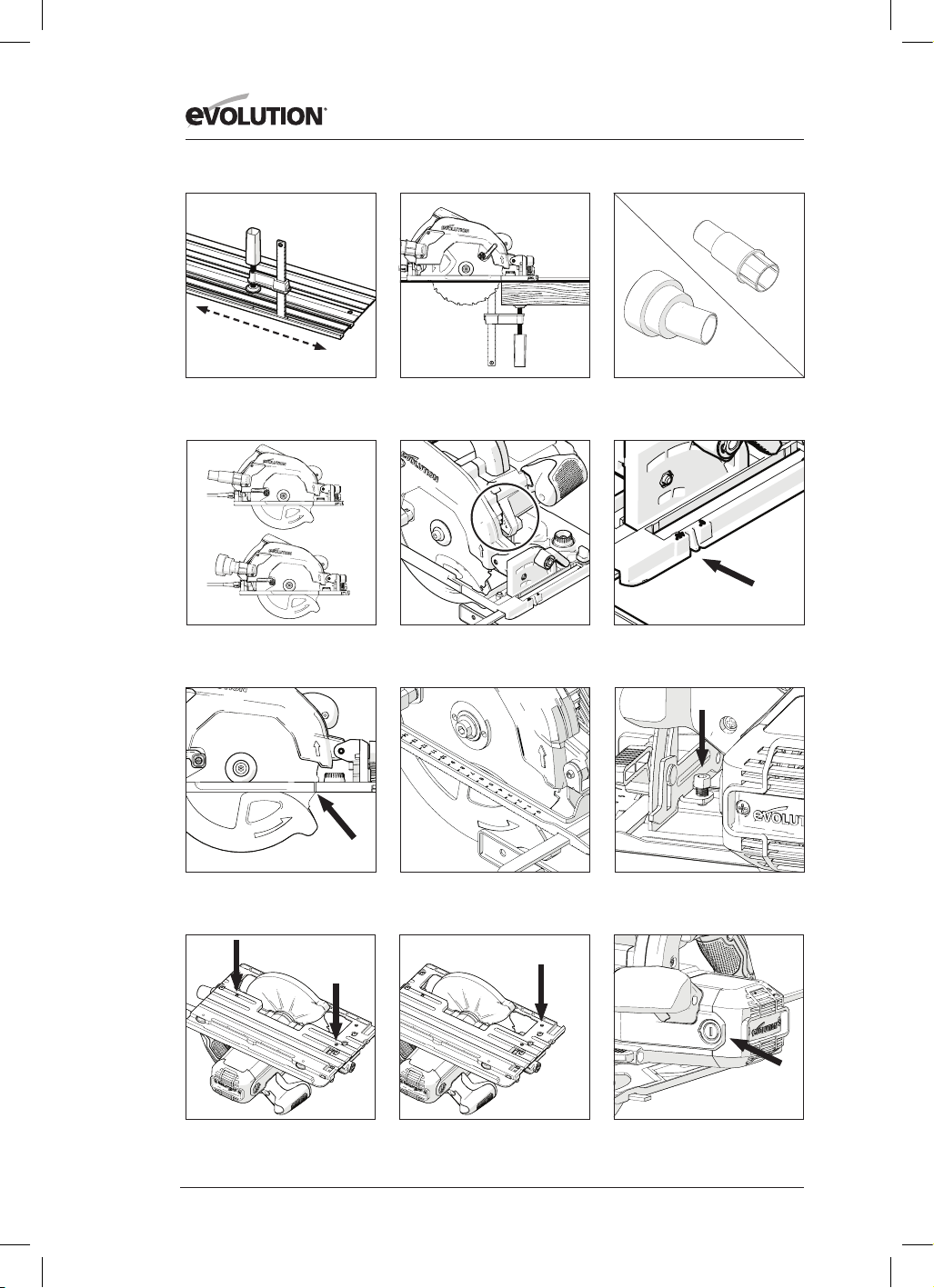
260
www.evolutionpowertools.com
Fig. 27Fig. 26
Fig. 25
Fig. 30 Fig. 31
Fig. 34
Fig. 24Fig. 23
Conector fantă praf SUA
Conector fantă praf UE
Fig. 28
Fig. 29
Fig. 32 Fig. 33

261
www.evolutionpowertools.com
RO
(10)
PREGĂTIREA
AVERTISMENT: Întotdeauna deconectați unealta
de la sursa de alimentare înainte de a efectua
orice reglaje.
Notă: Aceste unelte sunt prevăzute cu un cablu
de alimentare și ștecăr aprobate pentru țara
de destinație a utilizării. Nu transformaţi sau
modificați cablul de alimentare.
(10.1)
MONTAREA/DEMONTAREA
DISCULUI
AVERTISMENT:
Folosiți numai discuri Evolution
originale (sau cele aprobate de Evolution Power
Tools), care sunt proiectate pentru a fi utilizate
cu aceste unelte. Asigurați-vă că viteza maximă
a discului este compatibilă cu unealta. Efectuați
această operație numai cu unealta decuplată de
la sursa de alimentare.
Notă: Este recomandat că operatorul să poarte
mănuși de protecție atunci când manevrează
discul în timpul montării sau când schimbă
discurile pe unealtă.
• Localizați cheia imbus pentru schimbarea
discului, care se găsește în compartimentul
de depozitare încorporat (poziție similară la
toate uneltele).
(Fig. 1)
• Puneți fierăstrăul pe o suprafață sigură și
uniformă.
Notă: Cu grijă, toate uneltele pot fi puse în
echilibru pe partea plată a carcasei motorului,
(Fig. 2)
ceea ce face ca accesul la disc și la
sistemul de prindere al discului să fie foarte ușor.
• Localizați butonul de blocare a arborelui
uneltei (care este poziționat similar la toate
uneltele). Blocați arborele uneltei acționând
butonul de blocare a arborelui.
(Fig. 3)
.
Notă:
Rotind încet discul cu mâna, în timp ce
apăsați ușor butonul de blocare a arborelui,
arborele se va bloca.
• Folosind cheia imbus, slăbiți și îndepărtați
șurubul cu cap semi-îngropat al arborelui,
garniturile și flanșa exterioară de antrenare a
discului.
(Fig. 4)
Notă:
Șurubul cu cap semi-îngropat al arborelui
este prevăzut cu cap standard.
Rotiți șurubul în sens orar pentru a-l strânge.
Rotiți șurubul în sens anti-orar pentru a-l desface.
• Depozitați într-un loc sigur flanșa exterioară
a discului și garniturile.
• Rotiți scutul inferior al discului în sus spre
scutul superior al discului, folosind clapeta
manuală. (Fig. 5)
• Îndepărtați cu grijă discul (dacă este
montat) de pe unealtă.
• Curățați temeinic flanșele de antrenare
interioare și exterioare ale discului.
Notă: Flanșa interioară a discului poate fi
lăsată la locul ei, dacă se dorește, dar trebuie
verificată și curățată temeinic. Dacă este scoasă
din unealtă, trebuie pusă la loc în aceeași
direcţie în care era înainte de a fi scoasă.
• Curățați temeinic discul în jurul zonei
orificiului (pe ambele părți), acolo unde
flanșele discului vor atinge și strânge discul.
• Instalați discul (cel nou).
• Asigurați-vă că săgețile imprimate pe disc,
care indică direcția de rotire, corespund
săgeților de direcție a rotației de pe scuturile
de disc superior și inferior ale uneltei. (Fig. 6)
• Puneți la loc flanșa exterioară de angrenare,
șurubul cu cap semi-îngropat al arborelui și
toate garniturile.
Notă: Flanșa exterioară de angrenare are un
orificiu special fabricat care cuprinde două
„fante” paralele. (Fig. 7a) Aceste „fante” se
cuplează cu cele două „fante” pereche din tija
arborelui uneltei.
• Recuplați blocarea arborelui și strângeți bine
șurubul cu cap semi-îngropat al arborelui
folosind cheia imbus.
• Eliberați butonul de blocare a arborelui.
• Puneți cheia imbus înapoi în compartimentul
special de depozitare.
• Verificați dacă blocarea arborelui a fost anulată
complet, rotind manual discul.
• Verificați funcționarea scutului inferior al
discului.
Notă:
Exclusiv pentru piața nord-americană,
este inclusă o flanșă arbore dublă, care să
permită discuri cu alezaj de 1’’ (Fig. 7B) și discuri
cu alezaj de 5/8” (Fig. 7c)
(11) GHIDAJ MARGINI PARALELE
Un ghidaj pentru margini paralele (Fig. 8)
care poate fi deosebit de util când tăiați prin
despicare este furnizat cu toate uneltele CCS.
Ghidajul poate fi montat pe partea frontală a
plăcii de bază.
Brațul ghidajului trebuie să fie introdus prin
fantele dreptunghiulare aflate de-o parte și de
cealaltă (în față) a plăcii de bază din oțel presat și
culisat pe sub șurubul de blocare a reglării aflat
pe mijloc. (Fig. 9)

262
www.evolutionpowertools.com
Notă:
Ghidajul pentru margini paralele poate fi
montat pe oricare parte a plăcii de bază.
AVERTISMENT: Montați și reglați ghidajul
numai cu unealta decuplată de la sursa de
alimentare.
Notă: Brațul ghidajului pentru margini
paralele trebuie să treacă prin toate fantele
dreptunghiulare din placa de bază.
AVERTISMENT: Poate fi periculos să instalați
și să încercați să folosiți ghidajul de margine cu
brațul trecut doar printr-una (1) dintre fantele
dreptunghiulare ale plăcii de bază.
Reglați ghidajul de margine astfel încât să fie
la distanța necesară față de disc și strângeți
șurubul de reglare.
Verificați ca ghidajul de margine să fie paralel cu
discul fierăstrăului.
(12)
REGLAREA ADÂNCIMII DE TĂIERE
Notă: Toate uneltele CCS au aceleași accesorii/
fitinguri de reglare generală a adâncimii și fac
apel la aceeași tehnică de bază pentru setarea
adâncimii discului.
• Slăbiți mecanismul de blocare a adâncimii
reglate trăgând în sus de clapeta de operare.
(Fig. 10) (CCSL în imagine. Toate celelalte
modele sunt asemănătoare.)
• Reglați/repoziționați placa de bază pentru a
oferi adâncimea de tăiere necesară (măsura
în care discul iese deasupra plăcii de bază).
Notă: Un șubler de adâncime poate fi găsit
pe cadranul de reglare a adâncimii, iar un
indicator se află încorporat în zona alăturată a
scutului superior al discului uneltei. (Fig. 11)
Utilizarea acestor caracteristici poate facilita
reglarea.
Notă: Deși șublerul de adâncime și indicatorul
sunt foarte utile, ajutând la reglarea rapidă
a adâncimii, folosirea lor trebuie privită
întotdeauna ca ghidaj pentru setarea atinsă.
Dacă este necesară o tăietură cu o adâncime
precisă, atunci setarea discului trebuie verificată
cu o riglă de precizie (nefurnizată) sau cu ceva
asemănător și reglarea se va face în consecință.
• În majoritatea cazurilor, adâncimea de tăiere
trebuie setată la grosimea materialului ce se
va tăia, plus adâncimea a jumătate dintr-un
dinte de disc (de la vârful dintelui până la
rădăcina sa). (Fig.12)
• Strângeți mecanismul de blocare a adâncimii
reglate împingând în jos clapeta de operare
pentru a cupla blocajul în unealtă în poziția
dorită.
(13)
REGLAREA UNGHIULUI DE TĂIERE
(ÎNCLINAREA)
Toate aparatele CCSL & CCSX au opțiunea
înclinării discului (până la) 45˚, iar aparatele CCS
au opțiunea înclinării discului (până la) 60˚ spre
stânga. Astfel, sunt posibile tăieturile în unghi.
Notă:
Discul este în poziție verticală atunci când
echerul indică 0
°.
Notă: În cadranul de blocare a înclinării din
partea frontală a plăcii de bază este încorporat
un echer (0°- 45°). Dacă îl folosiți, veți putea
regla mai repede unghiul, însă el trebuie
perceput doar ca un mijloc ajutător.
Dacă este necesară o tăietură la un unghi precis,
atunci setarea discului trebuie verificată cu
un șablon de unghiuri vernier (nefurnizat) și
reglarea se va face în consecință.
• Slăbiți mecanismul de blocare a unghiului
aflat în partea frontală a uneltei, trăgând în
sus de clapetă. (Fig. 13)
• Înclinați discul la unghiul dorit, după cum
este indicat pe cadranul echerului. (Fig. 14)
• Strângeți bine mecanismul de blocare a
unghiului atunci când s-a atins unghiul de
înclinare dorit, apăsând clapeta în jos.
(14)
RECOMANDĂRI DE OPERARE
(VERIFICĂRI ÎNAINTE DE OPERARE)
Notă:
Întrucât toate mediile de operare sunt
unice și diverse, Evolution Power Tools oferă
următoarea recomandare generală privitoare la
procedurile și practicile de operare de care să țină
cont operatorul.
Această recomandare nu este exhaustivă, întrucât
Evolution Power Tools nu are nicio influență
asupra tipului de atelier sau mediu de lucru în
care aceste unelte vor fi folosite.
Recomandăm ca operatorul să ceară sfatul
unui specialist competent sau supervizorului
atelierului, în cazul în care are nelămuriri despre
utilizarea acestor unelte.
Este important să fie întreprinse verificări de
siguranță de rutină (la fiecare utilizare) înainte ca
operatorul să folosească unealta.

263
www.evolutionpowertools.com
RO
AVERTISMENT:
Verificările de siguranță
dinaintea utilizării trebuie întreprinse cu unealta
deconectată de la sursa de alimentare.
• Verificați dacă toate scuturile de siguranță
funcționează corect și dacă toate șuruburile/
mânerele de reglare sunt strânse bine.
• Verificați dacă discul este montat corect și
bine fixat. De asemenea, asigurați-vă că aveţi
discul corect pentru materialul ce va fi tăiat.
• Verificați integritatea cablului de alimentare.
• Oricând este posibil, prindeți piesa de
lucru pe o structură de suport rigidă, cum
ar fi bancul de lucru, menghina sau ceva
asemănător.
• Operatorul trebuie să știe întotdeauna poziția
cablului de alimentare, pentru a-l putea ocoli.
(15)
EPP
Operatorul trebuie să poarte tot timpul EPP
relevant (Echipament Personal de Protecție),
necesar pentru sarcina întreprinsă. Acesta poate
include ochelari de protecție, mască completă
de față, măști de praf, încălțăminte de protecție
etc.
Notă: Toate uneltele din seria CCS sunt
prevăzute cu un ventilator pentru reziduurile de
pe linia de tăiere. Aceasta direcționează aerul
de la un ventilator motorizat către zona din fața
discului, astfel menținând linia de tăiere relativ
curată.
Aceasta va permite operatorului să vadă și să
urmărească înaintarea discului pe tăietură,
menținând vizibile marcajele.
AVERTISMENT: Pulberile de praf, de orice fel,
sunt potențial dăunătoare pentru sănătate.
Unele materiale pot fi deosebit de dăunătoare,
iar operatorul trebuie să poarte întotdeauna o
mască de praf adecvată pentru materialul cu
care lucrează.
În cazul în care operatorul are dubii cât de mici
despre toxicitatea potențială a materialului
tăiat, trebuie să ceară sfatul și ajutorul unui
profesionist.
AVERTISMENT:
Aceste unelte nu trebuie să fie
folosite niciodată pentru a tăia azbest sau orice
material care conține sau se presupune că ar
conține azbest.
Consultați/informați autoritățile relevante și
cereți îndrumare suplimentară dacă suspectați o
eventuală contaminare cu azbest
.
(16)
COMUTATOR PORNIT/OPRIT
Notă:
Toate erăstraiele circulare
din familia CCS sunt prevăzute
cu un comutator de „pornire
sigură” pentru a crește siguranța
operatorului.
(Fig.15)
Pentru a porni motorul:
• Apăsați cu degetul mare butonul de
blocare de siguranță de pe partea laterală a
mânerului.
• Apăsați comutatorul.
Pentru a opri motorul:
• Eliberați comutatorul.
AVERTISMENT: Motorul nu trebuie pornit
niciodată când discul este în contact direct cu
orice suprafață a piesei de lucru.
Notă: Dispozitivele destinate pieței din
America de Nord sunt prevăzute cu un
comutator de PORNIRE/OPRIRE, care nu
include un comutator de „pornire de siguranță”.
AVERTISMENT: Dacă fierăstrăul este conectat
la sursa de curent (LED-ul este aprins în poziția
„PORNIT”), evitați pornirea accidentală a
motorului la ridicarea aparatului de pe bancul
de lucru sau alte locuri similare. Apăsarea
accidentală a comutatorului PORNIRE/OPRIRE
(poziționat pe mânerul principal) atunci când
ridicați aparatul de jos va porni motorul.
ȘINELE PENTRU TĂIERE
Aparatele din seria Evolution CCSX
(consultați pagina de specificații pentru
modelele la care se aplică) au fost
proiectate și concepute astfel încât să fie
compatibile cu șinele de tăiere.
Notă: Fierăstraiele circulare care pot fi utilizate
cu șine de tăiere vor avea prevăzut un canal de-a
lungul suprafeței inferioare a bazei de susținere
(Fig. 16) Aparatele Evolution prevăzute
cu acesta se pot fixa pe și pot fi utilizate
împreună cu majoritatea modelelor de șine de
tăiere (dispozitive de ghidare) disponibile în
momentul de față.
Notă: Consultați documentația furnizată
împreună cu șina de către producătorul
acesteia. Documentația furnizată va oferi, în
mod normal, instrucțiuni de asamblare a șinei,
precum și informații privind practicile de lucru

264
www.evolutionpowertools.com
sigure care trebuie implementate atunci când
se utilizează un astfel de echipament.
Șinele de tăiere pot fi utilizate în cazul în care:
• Utilizarea unui fierăstrău cu tăiere prin
despicare sau a unui ferăstrău circular
ar putea ridica riscuri pentru sănătate și
siguranță (H&S) sau alte probleme practice
la locul de muncă. De exemplu, atunci când
se lucrează pe un șantier de construcții unde
poate fi necesar un control foarte amănunțit
și precis (pe un acoperiș sau pe o platformă
de schelă etc.), utilizarea șinei de tăiere
poate oferi utilizatorului anumite posibilități
operaționale suplimentare (și de siguranță).
• Sunt necesare tăieri precise realizate pe sau
de-a lungul unor bucăți mari. De exemplu,
în cazul cadrelor, ușilor, panourilor mari sau
panourilor de perete etc, șina de tăiere/
dispozitivul de ghidare poate elimina
necesitatea folosirii în modul „liber” a unui
fierăstrău circular.
Notă: Aparatele Evolution compatibile cu șinele
de tăiere au două (2) came care se proiectează
în canalul bazei de susținere (una pentru fiecare
capăt). „Butoanele de rotire” (Fig. 17) permit
operatorului să rotească aceste came.
Reglarea acestor came va reduce ușor lățimea
efectivă a canalului bazei de susținere.
Acest lucru ar putea fi necesar în cazul unei
eventuale variații ușoare a lățimii șinei,
care poate apărea în timpul fabricării prin
extrudarea șinei. Șinele produse de diferiți
producători de șine pot, de asemenea, varia
ușor în lățime.
Notă: Operatorul trebuie să regleze aceste
came, astfel încât atunci când aparatul este
plasat corect pe șină, acesta să poată fi
deplasat înainte sau înapoi cu ușurință și fără
probleme, fără să apară vreo mișcare laterală
(neuniformă).
ȘINELE PENTRU TĂIERE
EVOLUTION
Anumite aparate Evolution (în funcție de
model și de piața de desfacere) sunt oferite cu
șină de tăiere.
Notă: Șinele de tăiere Evolution pot fi cumpărate
opțional de către client. Pentru detalii
suplimentare, contactați furnizorul sau Evolution
Power Tools.
ȘINA
Sistemul de șine Evolution constă din două (2)
sau trei (3) secțiuni atent extrudate, realizate
din aliaj. (Fig. 18) Aceste secțiuni trebuie
îmbinate cu ajutorul barelor de îmbinare
furnizate. (Fig. 19)
Pentru a îmbina secțiunile (Fig. 19):
• Glisați barele în sloturile în formă de „T”,
pe care le găsiți pe suprafața inferioară a
extrudărilor.
• Asigurați-vă că în ambele secțiuni care
urmează să fie îmbinate introduceți o
lungime egală (cu aproximație) a barelor.
• Strângeți șuruburile cu cap hexagonal,
pentru a fixa secțiunile.
Notă: Este important să lăsați un mic spațiu,
între 1 și 2 mm, între secțiunile îmbinate. Acest
lucru va garanta că atunci când fixați și utilizați
un fierăstrău circular pe o șină transversală
de tăiere Evolution, acesta va aluneca ușor pe
toată lungimea șinei.
PUNEREA ÎN FUNCȚIUNE A
FIERĂSTRĂULUI PE ȘINĂ
Notă: Următoarele îndrumări se referă la
fierăstrăul circular Evolution și la șina de tăiere
Evolution. Consultați informațiile furnizate de
producătorii fierăstrăului și/sau șinei de tăiere,
dacă trebuie să utilizați un fierăstrău circular
sau o șină de tăiere, altele decât Evolution.
Înainte de prima utilizare a șinei de tăiere
Evolution, banda de protecţie împotriva
așchiilor (Fig. 21) trebuie să se potrivească cu
fierăstrăul și lama.
Pentru a fixa fierăstrăul pe șină:
• Asamblați complet șina de tăiere.
• Consultați secțiunea intitulată „Poziționarea
și strângerea șinei”. Fixați șina pe o bucată
corespunzătoare de material de rezervă sau
rest de material.
• Setați lama de fierăstrău la o adâncime
corespunzătoare pentru restul de material de
prelucrat selectat.
• Asigurați-vă traiectoria lamei nu este blocată
în niciun fel.
• Consultați secțiunea „Poziționarea și
strângerea șinei”. Așezați corespunzător
fierăstrăul circular pe șină.
• Porniți motorul și lăsați-l să atingă viteza

265
www.evolutionpowertools.com
RO
maximă.
• Împingeți încet și cu atenție fierăstrăul
circular de-a lungul șinei până când lama
ajunge să taie toată lungimea benzii de
protecţie împotriva așchiilor.
Notă: Acest proces permite asocierea
fierăstrăului cu șina respectivă.
Dacă pe șina astfel pregătită se utilizează un alt
fierăstrău, este posibil ca banda de protecție
împotriva așchiilor să nu ofere același nivel de
protecție ca în cazul configurării fierăstrău-șină,
specific realizată.
Notă: Banda de protecție împotriva așchiilor
este considerată un element consumabil. În
timp, aceasta se va uza și se va toci și, prin
urmare, va trebui înlocuită. Este posibil să fie
necesară înlocuirea acesteia dacă se utilizează
un fierăstrău circular sau un disc de fierăstrău
(cu o lățime diferită de tăiere), diferite de cele
din configurația specifică originală.
BANDĂ DETAȘABILĂ DE PROTECȚIE
ÎMPOTRIVA AȘCHIILOR
Fiind un element consumabil, banda detașabilă
de protecţie împotriva așchiilor trebuie verificată
regulat, pentru a preveni deteriorarea sau
abraziunea cauzate de „uzură”. Înlocuiți banda
dacă sunt evidente urme semnificative de
deteriorare sau uzură.
Sunt disponibile benzi de schimb. Consultați-vă
furnizorul sau contactați Evolution, utilizând linia
telefonică de asistență corespunzătoare.
Banda detașabilă de protecţie împotriva așchiilor
furnizată este banda de schimb pentru cea
originală, montată. Nu trebuie decât să înlăturați
ușor de pe șină banda veche și să o înlocuiți cu
cea nouă.
Notă: Dacă instalați o nouă bandă, trebuie să
repetați procedeul de configurare fierăstrău-șină.
CLEMELE PENTRU ȘINĂ
EVOLUTION
(SE VINDE SEPARAT)
Clema de viteză Evolution (Fig. 22) este
concepută special pentru șina de tăiere
Evolution.
Notă:Puteți achiziționa cleme suplimentare de
la Evolution Power Tools sau de la furnizorul
dumneavoastră local.
Clemele Evolution se potrivesc și alunecă de-a
lungul sloturilor în formă de „T” care se găsesc
pe suprafața inferioară a extrudărilor din aliaj.
(Fig. 23)
Acest lucru permite operatorului să plaseze
clemele (câte una pentru fiecare capăt al șinei)
în poziții care să permită o siguranță maximă și
rigiditatea șinei de tăiere pe piesa de prelucrat.
POZIŢIONAREA ȘI FIXAREA ȘINEI
Notă: Următoarele îndrumări vă sunt oferite
sub formă de informații. Evolution nu are nicio
influență asupra mediilor sau a condițiilor de
lucru în care este folosit acest echipament.
AVERTISMENT: Dacă acest echipament
urmează să fie utilizat pe un șantier de
construcții, operatorul trebuie să consulte
persoana relevantă care răspunde de sănătate
și siguranță pentru alte eventuale cerințe sau
instrucțiuni de siguranță, specifice locației
respective.
• Marcați în mod clar piesa de prelucrat și, în
special, „linia de tăiere” de-a lungul căreia
este necesară deplasarea lamei fierăstrăului.
• Asamblați șina de tăiere cu atâtea secțiuni
câte sunt necesare pentru a acoperi piesa
de prelucrat, inclusiv o toleranță pentru o
eventuală prelungire necesară.
• Cu ajutorul clemelor de viteză Evolution
(opțiunea preferată) sau al clemelor
corespunzătoare „G” poziționați șina pe
piesa de prelucrat și fixați-o prin strângerea
clemelor.
• Asigurați-vă că marginea benzii de protecţie
împotriva așchiilor corespunde perfect cu
linia marcată de tăiere.
AVERTISMENT: Șina de tăiere trebuie să
depășească piesa de lucru pe marginea „de
intrare”. (Fig. 24)
Protecția inferioară a lamei va trebui să
fie retrasă manual și să pivoteze în sus în
dispozitivul de protecție superioară a lamei,
deoarece fierăstrăul circular este așezat pe șină.
AVERTISMENT: În această poziție, lama este
expusă. NU apăsați comutatorul până când
nu au fost efectuate următoarele verificări de
siguranță.
EFECTUAREA UNEI TĂIERI
• Efectuarea unei tăieri cu ajutorul șinei
de tăiere este foarte asemănătoare cu
efectuarea unei tăieri obișnuite, cu fierăstrăul

266
www.evolutionpowertools.com
circular. Toate procedurile și protocoalele
de siguranță care se aplică la utilizarea
fierăstrăului circular se vor aplica și în cazul
în care un astfel de fierăstrău este utilizat în
combinație cu o șină transversală de tăiere.
• Următoarele îndrumări, deși nu sunt
exhaustive, oferă câteva informații generale:
• Efectuați o verificare de siguranță pentru a
vă asigura că șina de tăiere este bine fixată
pe piesa de prelucrat și că piesa de prelucrat
este ea însăși sigură și nu se poate mișca în
timpul tăierii.
• Asigurați-vă că nu există obstrucții sub piesa
de prelucrat care ar putea împiedica sau
bloca deplasarea lamei fierăstrăului sau ar
putea fi deteriorate de lama fierăstrăului. •
Cablul de alimentare trebuie așezat în așa fel
încât să nu reprezinte un risc de împiedicare
(sau de orice altă natură). Verificați, în mod
deosebit, cablul de alimentare, având grijă să
nu poată intra în contact cu lama rotativă a
fierăstrăului.
• Operatorul trebuie să se asigure că, atunci
când împinge fierăstrăul pe șină, acesta își
poate menține o poziție sigură, un echilibru
bun și un control complet pe tot parcursul
operațiunii de tăiere. Trebuie exercitată
o atenție deosebită atunci când lama
fierăstrăului iese din piesa de prelucrat.
AVERTISMENT: P: În mod special, dacă
desfășurați activități la înălțime (poate fi cazul
și altor tipuri de circumstanțe), asigurați-vă
că orice eventuale bucăți de material tăiat
nu vor cădea și răni persoanele prezente la
fața locului. Operatorul va trebui să aibă în
vedere un mod de a reține sau prinde astfel
de eventuale bucăți de material tăiat. Pentru
îndrumări specifice, consultați persoana
responsabilă cu siguranța locului respectiv.
Notă: Operatorul trebuie să ia în considerare
efectuarea unei operații de probă cu fierăstrăul
deconectat de la rețeaua de alimentare, care să
confirme că procedura de tăiere este complet
sigură pe toată durata executării.
După terminarea operațiunii de tăiere,
operatorul trebuie să elibereze comutatorul
ON/OFF și să lase motorul să se oprească, astfel
lama se va opri și ea.
Atunci când fierăstrăul este ridicat de pe șina
de tăiere și de pe piesa de prelucrat, protecția
inferioară a lamei se va desface automat,
acoperind în întregime lama.
COLECTAREA PRAFULUI/
RESTURILOR
O duză adaptoare (Fig. 25) poate fi montată pe
toate aparatele CCS. Montarea duzei permite
conectarea aparatului la un dispozitiv de
colectare a prafului/resturilor.
Notă: Designul exact al duzei furnizate va
varia în funcție de tipul de model și de piața
de desfacere a aparatului. Duza furnizată este
compatibilă cu o gamă largă de dispozitive
de colectare a resturilor/prafului, disponibile
în momentul de față. Duza trebuie montată la
portul de evacuare a materialului tăiat.
(Fig. 26)
Notă: Dacă este nevoie, la duza adaptoare
poate fi montat un dispozitiv industrial de
extracție a prafului/resturilor. Dacă instalați
un astfel de dispozitiv, urmați instrucțiunile
producătorului și asigurați-vă că acesta are
capacitatea necesară pentru materialul tăiat
eliminat.
BECUL LED
Unele dintre aceste aparate (în funcție de
model și de piața de desfacere) sunt prevăzute
cu bec LED automat.
Notă: Dacă nu sunteți sigur cu ce caracteristici
este prevăzut aparatul dumneavoastră,
consultați pagina cu specificații inclusă în acest
manual. Becul LED este poziționat în partea
stângă (LH) a lamei. (Fig. 27)
Fasciculul becului LED va lumina partea
stângă a lamei, precum și orice eventuale linii
de marcaj prezente pe piesa de prelucrat.
Acest lucru are scopul de a ajuta operatorul
să anticipeze traiectoria lamei prin piesa de
prelucrat și să ofere astfel mai multă eficiență,
precizie și siguranță.
Notă: Funcționarea becului LED este automată.
Becul LED se va activa de îndată ce aparatul
este conectat la rețeaua de alimentare. Acest
lucru oferă operatorului o indicație vizuală
clară că aparatul a fost conectat cu succes
la sursa de alimentare și, prin urmare, este
alimentat (cu curent electric) și pregătit pentru
începerea operațiunilor de tăiere.
Notă: Ansamblul becului LED nu conține
componente care să poată fi reparate de

267
www.evolutionpowertools.com
RO
utilizator, iar direcția fasciculului de lumină
este setată din fabrică. Capacul protector
al obiectivului trebuie să fie protejat
împotriva depunerilor de praf etc. (a se vedea
Mentenanța) pentru a garanta păstrarea unei
luminozități optime a fasciculului proiectat.
AVERTISMENT: Curățați capacul obiectivului
numai atunci când aparatul este deconectat de
la rețeaua de alimentare, iar lama este complet
staționară.
ACCESORII INTEGRATE DE TĂIERE
Toate fierăstraiele circulare Evolution sunt
dotate cu diferite dispozitive de ghidare sau
accesorii de tăiere, proiectate pentru a ajuta
operatorul să realizeze o tăiere rapidă și
precisă în condiții de siguranță. Notă: Nu toate
aparatele vor prezenta toate caracteristicile de
mai jos.
Dispozitive de ghidare pentru linia de tăiere
la 0˚ și 45˚ (Fig. 28)
Pe marginea din față a bazei de susținere a
aparatului se află două (2) mici crestături, care
pe unele aparate sunt identificate cu o valoare
angulară. Aceste crestături indică poziția lamei
la ieșirea din piesa de prelucrat, când unghiul
de înclinare este setat la 0˚ (lama verticală) sau
la un unghi de 45˚.
Partea frontală a dispozitivului de ghidare a
lamei (Fig. 29)
Notă: Aparatele Evolution compatibile cu șina
de tăiere Evolution au o crestătură situată pe
marginea dreaptă (RH) a bazei de susținere.
Această crestătură indică poziția marginii
frontale a lamei atunci când lama este setată
la adâncimea maximă de tăiere. Această
caracteristică poate fi utilizată la plasarea și
poziționarea fierăstrăului pe șina de tăiere.
AVERTISMENT: Este important ca protecția
inferioară a lamei sau lama să nu atingă nicio
suprafață a piesei de prelucrat în timpul
poziționării inițiale a fierăstrăului pe șina de
tăiere.
Dispozitiv de ghidare cu riglă (Fig. 30)
Unele fierăstraie circulare Evolution sunt
prevăzute cu dispozitiv de ghidare cu riglă.
Acesta este poziționat pe partea frontală și/
sau părțile laterale ale bazei de susținere. Acest
dispozitiv de ghidare poate oferi sau anticipa
poziția aproximativă utilă a lamei fierăstrăului
în piesa de prelucrat.
ADAPTĂRILE SPECIALIZATE
Aparatul dumneavoastră Evolution are mai
multe componente și setări de inginerie de
precizie, cele mai multe dintre acestea fiind
setate din fabrică și adaptate pentru a garanta
o precizie constantă pe termen lung.
Probabil că nu vor fi niciodată necesare
întreținerea și ajustarea acestor componente
sau setări. În cazul în care considerați necesară
întreținerea sau reglarea (după o utilizare
considerabilă), Evolution vă recomandă să
contactați linia telefonică de asistență tehnică
pentru mai multe sfaturi și îndrumări.
Notă: Anumite proceduri de adaptare sunt
posibile numai având acces la anumite
cunoștințe și/sau echipamente de specialitate.
(17)
RECOMANDĂRI PRIVIND
TĂIEREA
AVERTISMENT:
Operatorul trebuie să cunoască
întotdeauna poziția și direcția cablului de
alimentare. Cablul de alimentare trebuie așezat
astfel încât să nu existe posibilitatea ca discul să
intre în contact cu el.
Cablul nu trebuie să reprezinte un risc de
împiedicare (sau de orice alt tip) pentru operator
sau persoanele prezente.
• Nu forțați unealta.
• Lăsați ca tăierea să fie efectuată prin
viteza discului. Performanța tăierii nu va fi
îmbunătățită aplicând presiune excesivă
pe unealtă, iar durata de viață a discului va
scădea.
• Atunci când folosiți ghidajul de margini
paralele, asigurați-vă că acesta este paralel
cu discul. Discul și/sau motorul pot suferi
deteriorări dacă unealta este folosită cu un
ghidaj de margini paralele reglat incorect.
• Poziționați partea din față a plăcii de bază
perpendicular pe piesa de lucru. Înainte de
a porni motorul, asigurați-vă că discul nu are
contact cu piesa de lucru.
• Când începeți o tăiere, aveți grijă să
introduceți discul în material încet, pentru a
nu deteriora dinții discului.
Notă:
Două (2) ghidaje pentru linia de tăiere
sunt prevăzute în partea frontală a plăcii de bază
pe uneltele CCSL (numai pentru unghiuri cu
înclinare de 0° și 45°).

268
www.evolutionpowertools.com
• Folosiți ambele mâini pentru a deplasa
fierăstrăul înainte prin piesa de lucru.
• Aplicați presiune constantă și uniformă
pentru a deplasa fierăstrăul înainte prin
piesa de lucru.
Notă: Toate uneltele din seria CCS au un
scut inferior de disc automat care are o
muchie frontală cu formă specială. Această
caracteristică face posibil ca scutul discului
să se retragă uniform și fără efort atunci când
discul pătrunde în piesa de lucru. Când discul
iese din piesa de lucru, scutul inferior va
reveni automat la poziția normală, acoperind
complet discul.
Notă: În unele situații, de exemplu, când
faceți o tăiere în miez într-o podea sau zid etc.,
poate fi un avantaj să retrageți manual scutul
inferior al discului.
O clapetă acționată cu degetul mare este
prevăzută pe scutul inferior al discului. Cu
atenție, un operator priceput poate retrage
manual scutul discului, fie parțial, fie complet,
permițând efectuarea tăieturilor în miez.
AVERTISMENT:
Dacă retrageți manual scutul
discului, trebuie să aveți grijă ca mâna sau
degetele să nu atingă nicio parte a discului.
Când finalizați o tăietură:
• Eliberați comutatorul PORNIT/OPRIT.
• Lăsați discul să se oprească complet.
• Scoateți unealta din piesa de lucru, lăsând
scutul inferior să revină la poziția normală,
acoperind complet discul.
AVERTISMENT: În cazul în care motorul se
oprește sau se blochează în timp ce efectuați
o tăiere, eliberați imediat comutatorul.
Deconectați unealta de la sursa de alimentare
și îndepărtați unealta de piesa de lucru.
Analizați cauza problemei și recticați, dacă e
posibil.
Încercați să reporniți motorul numai când
sunteți absolut siguri că este sigur să faceți
aceasta.
FANTĂ DE ELIMINARE MATERIAL
TĂIAT
AVERTISMENT:
Nu utilizați sacul de praf și
racordul de aspirație atunci când realizați tăieturi
în materiale metalice, inclusiv în lemn cu cuie.
(18)ÎNTREȚINERE ȘI REGLAJE
Poziția 0° (disc vertical) poate fi reglată.
AVERTISMENT: Unealta trebuie să fie
deconectată de la sursa de alimentare atunci
când încercați această operațiune.
Pentru a verifica poziția 0°:
• Fixați discul la poziția 0° cu mecanismul de
înclinare la limita sa.
• Verificați discul prin comparare cu placa
de bază, folosind un echer de precizie
(nefurnizat). Aveți grijă să evitați vârfurile
TCT ale dinților. Discul trebuie să fie la exact
90° pe placa de bază.
Notă: Scutul inferior al discului trebuie rotit
(manual) în sus spre scutul superior al discului.
Acest lucru va ajuta la poziționarea precisă a
echerului și, astfel, la procesul de verificare.
Dacă este nevoie de reglare:
R165CCSL și 185CCS
Rotiți șurubul de reglare (Fig. 31) în sens orar
sau anti-orar folosind o cheie imbus de 4 mm
(nefurnizată) până când discul este la exact 90°
pe placa de bază.
R185CCSX și 185CCSX
Rotiți șuruburile de reglare (Fig. 32) în sens
orar sau anti-orar folosind o cheie imbus de
3 mm (nefurnizată) până când discul este la
exact 90° pe placa de bază.
Pentru verificarea poziției de 45˚
(R185CCSX și 185CCSX+ ):
• Fixați discul la poziția 45° cu mecanismul de
înclinare la limita sa.
• Verificați discul prin comparare cu placa
de bază, folosind un echer de precizie
(nefurnizat). Aveți grijă să evitați vârfurile TCT
ale dinților. Discul trebuie să fie la exact 45°
pe placa de bază.
Rotiți șuruburile de reglare (Fig. 33) în sens
orar sau anti-orar folosind o cheie imbus de
3 mm (nefurnizată) până când discul este la
exact 45° pe placa de bază.
(19) VERIFICAREA ȘI ÎNLOCUIREA
PERIILOR CU CĂRBUNE
AVERTISMENT: Deconectați unealta de la
sursa de alimentare înainte de a verifica sau
269
www.evolutionpowertools.com
RO
repara periile cu cărbune.
Notă: Înlocuiți ambele perii cu cărbune dacă
vreuna dintre ele are mai puțin de 6 mm de
cărbune sau dacă arcul sau firul este deteriorat
sau ars.
Pentru a îndepărta periile:
• Desfaceți capsele de plastic din spatele
carcasei motorului. (Fig. 34) Avei grijă, căci
capsele sunt cu arc.
• Scoateți periile cu arcurile corespunzătoare.
• Dacă este necesară înlocuirea, puneți perii
noi și fixați capsele la loc.
Notă: Pot fi folosite periile uzate, care au fost
reparate, însă numai dacă sunt puse în aceeași
poziție și sunt introduse în aceeași ordine în
care erau înainte de a fi scoase din unealtă.
• Lăsați motorul să meargă fără sarcină timp
de aproximativ 5 minute. Astfel, noile
perii vor fi „rodate” și motorul va funcționa
eficient.
• Pot apărea scântei până când periile se
rodează complet.
(20)
ÎNTREȚINERE ȘI CURĂȚARE
GENERALĂ
Notă: Toate operațiunile de întreținere trebuie
întreprinse cu unealta oprită și deconectată de
la sursa de alimentare.
• Verificați regulat dacă toate funcțiile de
siguranță și scuturile funcționează corect.
Folosiți această unealtă doar dacă toate
scuturile/funcțiile de siguranță sunt complet
operaționale.
• Toți pivoții din aceste unelte sunt lubrifiați
pe viață. Nu este necesară lubrifierea lor.
Folosiți o cârpă curată și puțin umezită pentru
a curăța piesele plastice ale uneltei. Nu
folosiți solvenți sau produse similare, care pot
deteriora piesele de plastic.
Îndepărtați urmele de praf sau alte impurități
de pe capacul obiectivului modulului LED.
AVERTISMENT:
Nu încercați să curățați
introducând obiecte ascuțite în fantele carcasei
uneltei etc. Fantele pentru aer ale uneltei trebuie
curățate folosind aer comprimat uscat.
Notă:
Operatorul trebuie să poarte EPP necesar
atunci când folosește aerul comprimat uscat ca
mijloc de curățare.
(21)
PROTEJAREA MEDIULUI
ÎNCONJURĂTOR
Deșeurile din produse electrice nu trebuie
aruncate împreună cu resturile menajere. Vă
rugăm să reciclați la locurile special amenajate.
Adresați-vă autorității locale sau vânzătorului
pentru îndrumare cu privire la reciclare.
270
www.evolutionpowertools.com
EC DECLARATION OF CONFORMITY
Fabricantul produsului acoperit de prezenta Declarație este:
UK: Evolution Power Tools Ltd, Venture One, Longacre Close, Holbrook Industrial Estate, Sheeld, S20 3FR.
FR: Evolution Power Tools SAS, 61 Avenue Lafontaine, 33560, Carbon-Blanc, Bordeaux, France.
Prin prezenta, fabricantul declară că unealta, așa cum este descrisă în această declarație, respectă toate prevederile
relevante ale Directivei privind echipamentele tehnice, precum și alte directive specifice, după cum se detaliază mai jos.
Fabricantul mai declară că unealta, așa cum este descrisă în această declarație, acolo unde este cazul, respectă prevederile
relevante ale Cerințelor esențiale de sănătate și siguranță.
Directivele acoperite de această Declarație sunt cele detaliate mai jos:
Și este în conformitate cu cerințele aplicabile ale următoarelor documente:
EN IEC 55014-1:2021 • EN IEC 55014-2:2021 • EN IEC 61000-3-2:2019/A1:2021 •
EN 62841-1:2015/A11:2022 • EN62841-2-5:2014 • EN 55014-1:2017+A11:2020 • EN 55014-2:2015
EN 61000-3-2: 2014 (220-240V)• EN IEC 61000-3-2:2019 (220-240V) •
EN 61000-3-3:2013+A1:2019 (026-0001) • EN IEC 61000-3-11:2019 (220-240V cu exceptia
modelului 026-0001)
Product Details
Descriere: R165CCSL 165mm (6-1/2”) Circular Saw
Nr. model Evolution: 026-0001 / 026-0002 / 026-0003
Description: R185CCS 185mm (7-1/4”) Circular Saw
Model No: 027-0001C / 027-0002C / 027-0003C
Description: R185CCSX 185mm (7-1/4”) Circular Saw
Model No: 027-0001 / 027-0002 / 027-0003
Description: R185CCSX+ 185mm (7-1/4”) Circular Saw
Model No: 027-0001A / 027-0002A / 027-0003A
Nume de marcă: EVOLUTION POWER TOOLS LIMITED
Voltaj: 220-240V / 110V ~ 50Hz
Putere consumată: R165CCSL - 1200W
R185CCS, R185CCSX & R185CCSX+ - 1600W
Documentația tehnică necesară pentru a demonstra că productul respectă cerințele directivei a fost completată și este
disponibilă pentru a fi inspectată de autoritățile relevante și demonstrează că dosarul nostru tehnic conține documentele
enumerate mai sus și că acestea reprezintă standardele corecte pentru produs, așa cum este descris mai sus.
Numele și adresa deținătorului documentației tehnice.
Semnătura: Numele cu litere de tipar: Barry Bloomer
Director Achiziții și Aprovizionare
Data: 21/02/23
UK: Evolution Power Tools Ltd, Venture One, Longacre Close, Holbrook Industrial Estate, Sheeld, S20 3FR.
FR: Evolution Power Tools SAS, 61 Avenue Lafontaine, 33560, Carbon-Blanc, Bordeaux, France.
2006/42/CE. Directiva privind echipamentele tehnice.
2014/30/UE. Directiva privind compatibilitatea electromagnetică.
2011/65/EU. &
2015/863/EU.
Directiva privind restricțiile de utilizare a anumitor substanțe periculoase cu echipamentele electrice
2012/19/UE. Directiva privind deșeurile de echipamente electrice și electronice (DEEE)

271
www.evolutionpowertools.com
RO
Notes

V10
USA
Evolution Power Tools LLC
8363 Research Drive
Davenport, IA
52806
T: +1-833-MULTI-SAW (Toll Free)
FR
Evolution Power Tools SAS
61 Avenue Lafontaine
33560, Carbon-Blanc
Bordeaux
T: +33 (0)5 57 30 61 89
UK
Evolution Power Tools Ltd
Venture One, Longacre Close
Holbrook Industrial Estate
Sheffield, S20 3FR
T: +44 (0)114 251 1022
AUS
Total Tools (Importing) Pty Ltd
20 Thackray Road
Port Melbourne
Vic 3207
T: 03 9261 1900
EPT QR CODE
DE +44 (0)114 251 1022
ES +34 91 114 73 85
NL +44 (0)114 251 1022
PL +48 33 821 0922
PT +34 91 114 73 85
RO +44 (0) 114 2050458
RU +7 499 350 67 69
TR +90 (0) 312 9001810