Portofino
INSTALLATION, OPERATING AND MAINTENANCE GUIDE

2
220-240V 50/60Hz

3
Summary
I GENERAL ....................................................................................................... 4
II WARNINGS ...................................................................................................... 4
III INSTALLATION ................................................................................................. 9
III.1 AIR TREATMENT ............................................................................................. 9
III.2 PRELIMINARY INDICATIONS ............................................................................... 10
III.3 INSTALLATION .............................................................................................. 13
III.3.a INSTALLATION OF THE INDUCTION HOB .......................................................... 14
III.3.b CONSTRUCTION INSTRUCTIONS - OUTLET ON PLINTH ........................................ 20
III.3.c CONSTRUCTION INSTRUCTIONS - REAR DISCHARGE ............................................ 21
III.3.d ASSEMBLING THE AIR VENTING PIPE .............................................................. 22
III.4 ELECTRICAL CONNECTION ................................................................................ 22
IV OPERATION .................................................................................................... 25
IV.1 DESCRIPTION OF THE EXTRACTING INDUCTION HOB ................................................. 25
IV.1.a TECHNICAL CHARACTERISTICS ..................................................................... 25
IV.1.b MAIN CONTROL CHARACTERISTICS OF THE EXTRACTOR HOB ................................. 26
IV.2 CONTAINERS FOR COOKING .............................................................................. 27
IV.2.a QUALITY OF THE PANS .............................................................................. 27
IV.2.b DIMENSIONS OF PANS ................................................................................ 27
IV.3 INDUCTION HOB ............................................................................................ 28
IV.3.a COOKING ZONE DISPLAY ............................................................................ 28
IV.3.b HOB CHARACTERISTICS .............................................................................. 29
IV.3.c HOB CONFIGURATION ............................................................................... 29
IV.3.d HOB OPERATION ..................................................................................... 32
IV.4 EXTRACTION ................................................................................................ 40
IV.4.a PRELIMINARY INDICATIONS ......................................................................... 40
IV.4.b EXTRACTION OPERATION ........................................................................... 41
V MAINTENANCE AND CLEANING ............................................................................. 44
V.1 CLEANING THE EXTRACTOR INDUCTION HOB .......................................................... 44
VI TROUBLESHOOTING .......................................................................................... 49
VI.1 ERRORS / TROUBLESHOOTING ........................................................................... 49
VI.2 ASSISTANCE SERVICE ...................................................................................... 50
VII DECOMMISSIONING ........................................................................................ 51
VII.1 DECOMMISSIONING ........................................................................................ 51
VII.2 DISASSEMBLY ............................................................................................... 51
VII.3 PROTECTING THE ENVIRONMENT ....................................................................... 51
VII.4 DISPOSAL ................................................................................................... 51

4
I GENERAL
Installation, operating and maintenance instructions for extraction hob model PERFECTO.
220-240V 50/60Hz
READ AND SAVE THESE INSTRUCTIONS
II WARNINGS
CAUTION: Automatically Operated Device – To Reduce The Risk Of Injury
Disconnect From Power Supply Before Servicing.
WARNING: To Reduce The Risk Of Fire Or Electric Shock, Do Not Use This Fan With Any Solid-State Speed Control
Device.
PAY ATTENTION TO:
A) THE NEED FOR FREQUENT CLEANING OF ALL GREASE FROM THE FAN AND FROM ALL OTHER GREASE-LADEN
SURFACES;
B) THE NEED FOR FREQUENT REMOVAL AND CLEANING OF ANY FILTER UNIT PROVIDED.
WARNING: To provide protection against electric shock, connect to properly grounded outlets only.
For Residential Use Only
WARNING: GROUNDING INSTRUCTIONS
This appliance must be grounded. In the event of an electrical short circuit, grounding reduces the risk of electric
shock by providing an escape wire for the electric current. This appliance is equipped with a cord having a
grounding wire with a grounding plug. The plug must be plugged into an outlet that is properly installed and
grounded.
WARNING – Improper grounding can result in a risk of electric shock.
Consult a qualified electrician if the grounding instructions are not completely understood, or if doubt exists as to
whether the appliance is properly grounded. Do not use an extension cord. If the power supply cord is too short,
have a qualified electrician install an outlet near the appliance.
WARNING – TO REDUCE THE RISK OF FIRE, USE ONLY METAL DUCTWORK.
WARNING – TO REDUCE THE RISK OF A RANGE TOP GREASE FIRE:
a) Never leave surface units unattended at high settings. Boilovers cause smoking and greasy spillovers that may
ignite. Heat oils slowly on low or medium settings.
b) Always turn hood ON when cooking at high heat or when flambeing food (i.e. Crepes Suzette, Cherries Jubilee,
Peppercorn Beef Flambe’).
c) Clean ventilating fans frequently. Grease should not be allowed to accumulate on fan or filter.
d) Use proper pan size. Always use cookware appropriate for the size of the surface element.
WARNING – TO REDUCE THE RISK OF INJURY TO PERSONS IN THE EVENT OF A RANGE TOP GREASE FIRE, OBSERVE
THE FOLLOWING:
a) SMOTHER FLAMES with a close-fitting lid, cookie sheet, or metal tray, then turn off the burner.
BE CAREFUL TO PREVENT BURNS. If the flames do not go out immediately,
EVACUATE AND CALL THE FIRE DEPARTMENT.
b) NEVER PICK UP A FLAMING PAN – You may be burned.
c) DO NOT USE WATER, including wet dishcloths or towels – a violent steam explosion will result.
d) Use an extinguisher ONLY if:
1) You know you have a Class ABC extinguisher, and you already know how to operate it.
2) The fire is small and contained in the area where it started.
3) The fire department is being called.
4) You can fight the fire with your back to an exit.
THE MINIMUM DISTANCE BETWEEN THE SUPPORTING SURFACE OF THE COOKING HOB AND THE LOWEST PART OF
THE RANGE HOOD MUST BE NOT LESS THAN 26IN (65 CM) WITH A GAS HOB.
5
READ AND SAVE THESE INSTRUCTIONS
Keep these instructions in a safe place and pass them on to any future user. Read these instructions carefully before
installing or using the range hood.
Before connecting the appliance to the power supply make sure that the voltage (V) and frequency (Hz) listed on the
data plate correspond with the household electrical supply. This data must correspond to prevent appliance damage.
Installation work and repairs should only be performed by a qualified technician under all applicable codes and standards.
Repairs and other work by unqualified persons could be dangerous.
In the event of a fault, please contact the Technical Service authorized to provide genuine parts. When contacting the
Technical Service, please quote the model and the serial number of your appliance. These are shown on the data plate.
Ensure that power to the appliance is OFF while the appliance is not in use.
During thunderstorms switch-off the main switch of the house electrical system or if the device is equipped with a plug,
simply unplug it.
Use this appliance only in the manner intended by the manufacturer and no other than exhausting cooking fumes on
domestic kitchens.
The manufacturer does not accept any liability for damages caused by people, animals, or things, by installation and
maintenance mistakes, or by any illegitimate use.
Observe the following essential safety instructions during the use of any electrical appliance:
•This appliance is not intended for use by persons (including children) with reduced physical, sensory or mental
capabilities, or lack of experience and knowledge unless they have been given supervision or instruction concerning the
use of the appliance by a person responsible for their safety. Children should be supervised to ensure that they do not
play with the appliance.
•To prevent the risk of fire it is compulsory to disconnect the appliance from the power supply before cleaning or
servicing the hood;
•Do not pull, take off, or twist the cable coming out from the appliance, even though this has been disconnected from
the main power supply.
•Do not sprinkle or throw any water directly on the appliance.
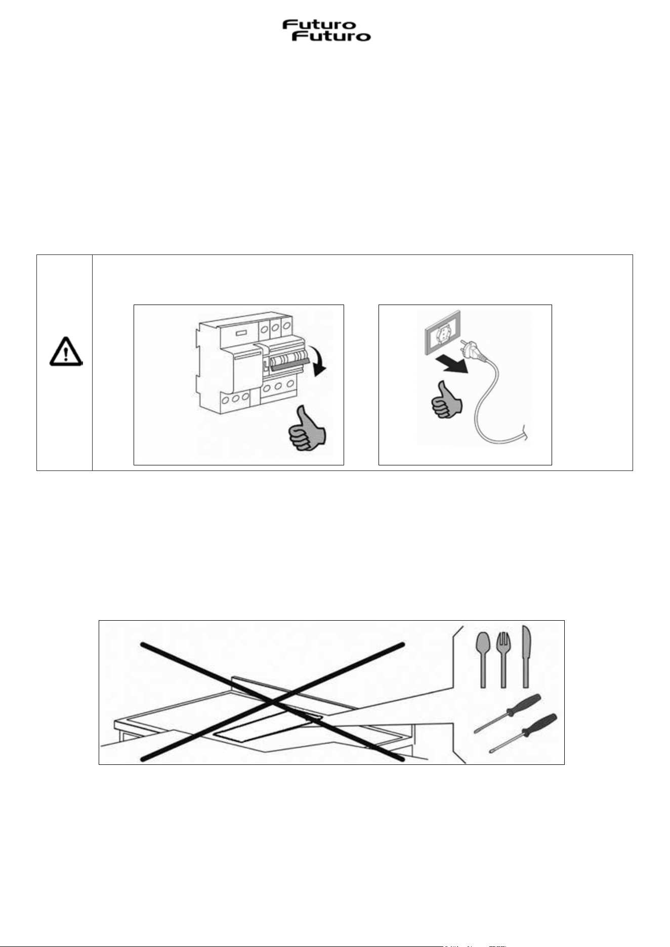
•Do not stick any sharp tool inside the exhausting holes and into the air outlet.
•Do not take out the filters to reach the internal sides of the appliance in case the main switch of the house electrical
system is not off.
•Do not flambé or grill with an open flame beneath the hood. Flames could be drawn up into the hood by the suction
and the filters may ignite.
•Pay particular attention while frying. Heat oils slowly on low or medium settings.
•CAUTION: Accessible parts may become hot when used with cooking appliances.
•It is forbidden to use the hood as a support surface unless it is expressly indicated.
•Only use the fixing screws supplied with the product for installation.
The appliance may have different aesthetics compared to what is illustrated in the drawings in this
manual, however the instructions for installation, use and maintenance remain the same.
The manufacturer strives for continuous improvements.
For this reason, the text and illustrations in this manual may be changed without notice.
CAUTION: Accessible parts may become hot when used with cooking appliances.
6
x The appliance is manufactured according to the safety standards in force.
x Use of the appliance cannot be different from that for which it was built, i.e. as an extractor
induction hob, for the cooking of food and the extraction of cooking fumes, installed in domestic
kitchens.
x The manufacturer disclaims all liability for any damage caused to persons, animals or property,
installation and maintenance errors, or misuse.
x Before connecting the appliance to the mains, check the serial number plate (located on the
lower part of the appliance) to make sure that the voltage and power correspond to those of the
mains and that the connection socket is suitable. If in doubt, contact a qualified electrician.
Attention! Before any cleaning or maintenance operation or in the event of
thunderstorms, disconnect the appliance by setting the main system switch to "off"
(Fig.2.1) or by unplugging it (Fig.2.2).
x When the extractor hob is in operation, the parts of the extractor hob adjacent to the induction
hobs can also become hot.
x There is a possibility of fire if cleaning operations are not carried out according to the
instructions.
x The appliance must not be cleaned with steam or high-pressure cleaners.
x It is forbidden to introduce any object through the glass extraction flap (Fig.2.3).
Fig. 2.1
Fig. 2.2
Fig. 2.3
7
x Do not use the appliance to heat the room.
x Pay attention to the electrical connection of other appliances in the immediate vicinity that must
not come into contact with the hot appliance.
x It is forbidden to pull, detach or twist the electrical cables exiting the appliance, even if it is
disconnected from the power supply.
x Cooker hoods and other cooking fume extractors can adversely affect the safe operation of
appliances that burn gas or other fuels (including those in other rooms) due to the backflow of flue
gases. These gases have the potential to cause carbon monoxide poisoning. After installing a cooker
hood or other kitchen fume extractor, flow gas appliances should be tested for function by a
competent person to ensure that no backflow of flue gases occurs.
x It is forbidden to cook on the flame.
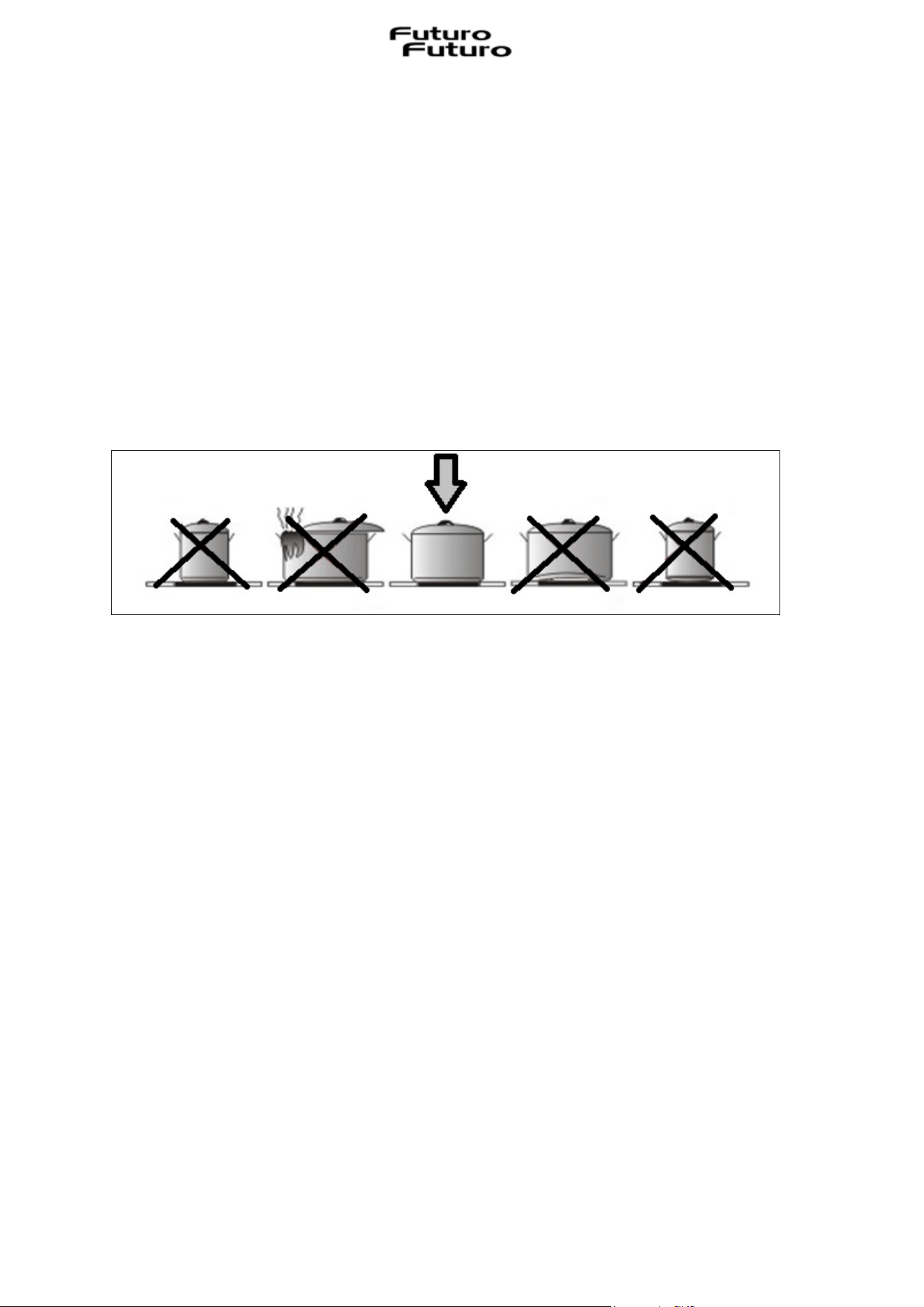
x To avoid any unwanted interference on the control panel (Touch Control “TC”), position suitable
pans centred on the points marked on the glass ceramic surface.
Precautions before use
· Unpack all the materials.
· The installation and connection of the appliance must be performed by authorised specialists. The
manufacturer cannot be held responsible for damage caused by installation or connection errors.
· To be used, the appliance must be well equipped and installed in a kitchen unit and on an adapted
and approved work surface.
· This appliance is intended solely for the cooking of food and excludes any other domestic,
commercial or industrial use.
· Remove all labels and stickers from the ceramic glass.
· Do not change or alter the appliance.
· The hob cannot be used as a free-standing or work surface.
· The appliance must be earthed and wired in accordance with the local standards.
· Do not use any extension cord to connect it or multiple sockets.
· The appliance must not be used on top of a dishwasher or tumble dryer: steam can damage
electronic appliances.
· The appliance is not designed to be operated using an external timer or separate remote control
system.

8
Use of the appliance
· After use, switch off the hob using its control device and do not rely on the pot detector.
· Turn off the heating zones after use.
· Be vigilant when cooking with fat or oils that could catch fire quickly.
· Be careful not to burn yourself during or after using the appliance.
· Make sure that there are no cables from any appliance, fixed or mobile, in contact with the glass
or hot pot.
· Magnetic objects (credit cards, floppy disks, calculators) must not be placed near the plugged-in
device.
· Metallic objects such as knives, forks, spoons and lids must not be placed on the hob surface as
they can heat up.
· In general, do not place metal objects except for heating containers on the glass surface. In the
event of unexpected or residual overheating, these can heat up, melt or even burn.
· Never cover the appliance with a cloth or protective sheet. This could become very hot and catch
fire.
· This appliance may be used by children aged 10 years or over and by persons with reduced physical,
sensory or mental capabilities or who lack experience and knowledge only if they have been
supervised or instructed in safe use of the appliance and understand the dangers.
· Children must not play with the appliance.
· Cleaning and maintenance by the user must not be performed by children without supervision.
Precautions to avoid damaging the appliance
· Rough pot bases or damaged pans (not enamelled cast iron pans) can damage the ceramic glass.
· Sand or other abrasive materials can damage the ceramic glass.
· Avoid dropping objects, even small ones, on the ceramic glass.
· Do not strike the edges of the glass with pans.
· Make sure that the ventilation of the appliance works according to the manufacturer's instructions.
· Do not place or leave empty pans on glass ceramic hobs.
· Sugar, synthetic materials or aluminium foil must not come into contact with the heating zones.
These can cause breakage or other alterations of the glass ceramic glass when cooling: switch on
the appliance and remove them immediately from the hot heating zone (be careful: do not burn
yourself).
· WARNING: unattended cooking on a hob with fat or oil can be dangerous and can cause fires.
· ATTENTION: the cooking process must be monitored. A short-term cooking process must be
monitored constantly.
· ATTENTION: fire hazard: do not place objects on the cooking surface.
· Never place hot containers on the control panel.
· Adequate ventilation must be ensured on the front and back of the unit so that the air can
circulate.
· If a drawer is located under the built-in appliance, make sure that the space between the contents
of the drawer and the underside of the induction hob is large enough (30 mm). This is essential to
ensure correct ventilation.
· Never place flammable objects (e.g. sprays) in the drawer located under the glass ceramic hob.
Any cutlery drawers must be heat-resistant.
9
Precautions in case of equipment fault
· If a defect is found, switch off the appliance and interrupt the power supply.
· If the ceramic glass is broken or cracked, it is necessary to disconnect the appliance and contact
the after-sales assistance.
· Repairs must be performed by specialists. Do not open the appliance yourself.
· WARNING: If the surface is cracked, switch off the appliance to avoid the possibility of electric
shock.
Other protections
· Make sure that the pot/container is always centred on the cooking zone marked on the hob.
· Wearers of pacemakers must be aware that the magnetic field could affect its operation. It is
advisable to ask the retailer or doctor for information.
· Do not use containers made of aluminium or synthetic material: they could melt in the cooking
zones that are still hot.
· NEVER attempt to extinguish a fire with water, but switch off the appliance and cover the
flame, e.g. with a lid or fire blanket.
III
INSTALLATION
III.1 AIR TREATMENT
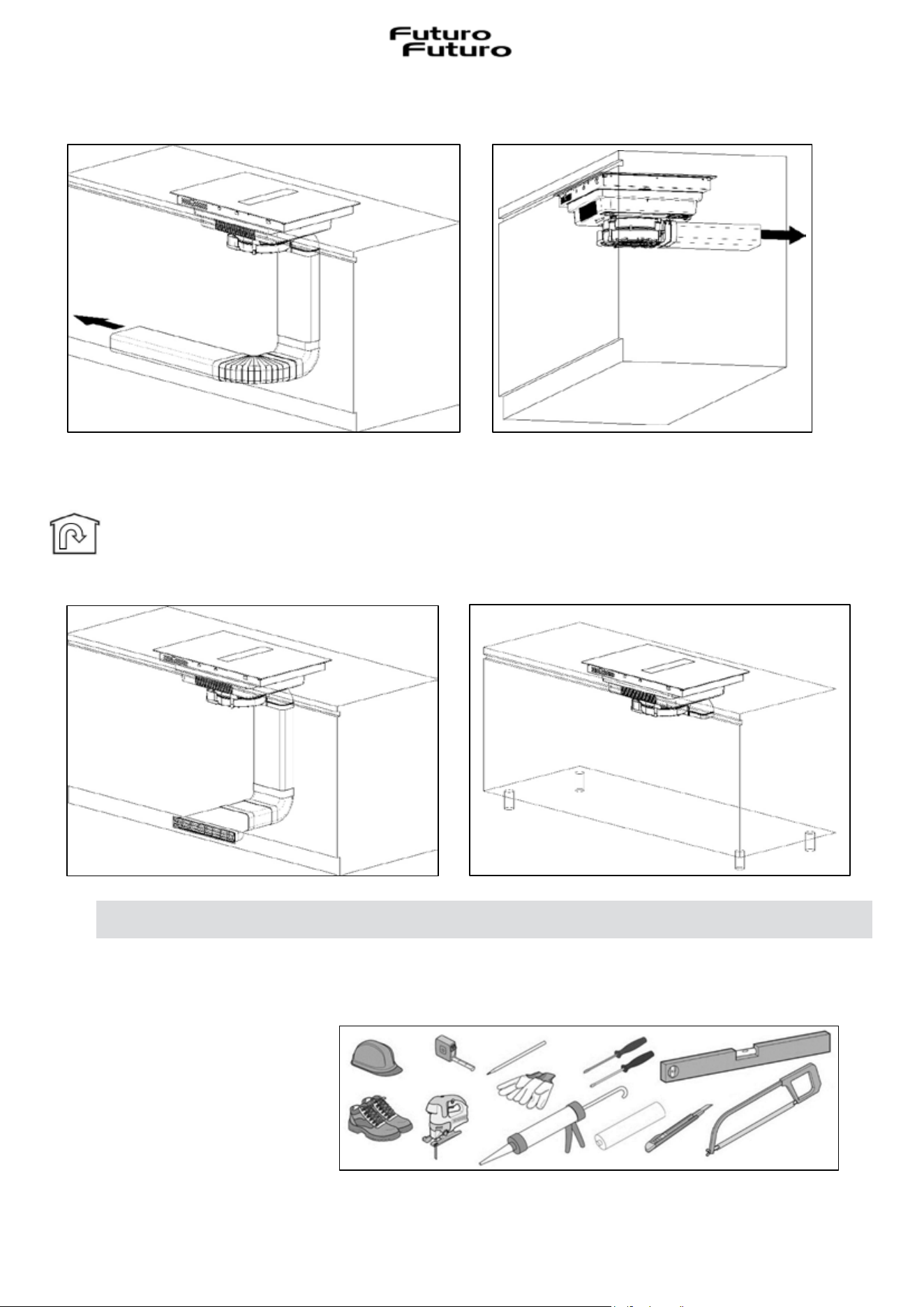
This extraction system allows the treatment of cooking fumes. The system can be used in extraction
or filtering mode (long life ceramic odour filter kit or kit with plasma filter available separately).
Extracting (external evacuation). Fumes from the kitchen are expelled outside through
the pipe (not supplied with the appliance) connected to the motor exhaust fitting.
Attention! In no case must the pipe be connected to combustion exhaust ducts
(stoves, boilers, burners, etc.).
THE USE OF POOR QUALITY COOKWARE OR ANY INDUCTION ADAPTER PLATE FOR NON-
MAGNETIC COOKWARE WILL VOID THE WARRANTY. IN THIS CASE, THE MANUFACTURER
CANNOT BE HELD RESPONSIBLE FOR ANY DAMAGE CAUSED TO THE HOB AND/OR TO THE
SURROUNDING ENVIRONMENT.
10
The use of long pipes, with many bends, corrugated and with a smaller section than that of the
motor outlet will cause a decrease in extraction performance and a possible increase in noise.
Filtering (internal recycling). The fumes pass through the long life ceramic odour filters
(which can be ordered separately as an accessory) to be purified and recycled in the kitchen
environment.
III.2 PRELIMINARY INDICATIONS
Read the entire instruction booklet before installing and using the equipment.
For the installation of the appliance, safety equipment and a series of devices are required as shown
in Fig.3.2.1.
Fig. 3.2.1
11
The extraction hob is equipped with all the fixings necessary for its installation and suitable for
most units.
Important: just in case, more screws than necessary for installation are supplied, so it is normal to
have some remaining after installation.
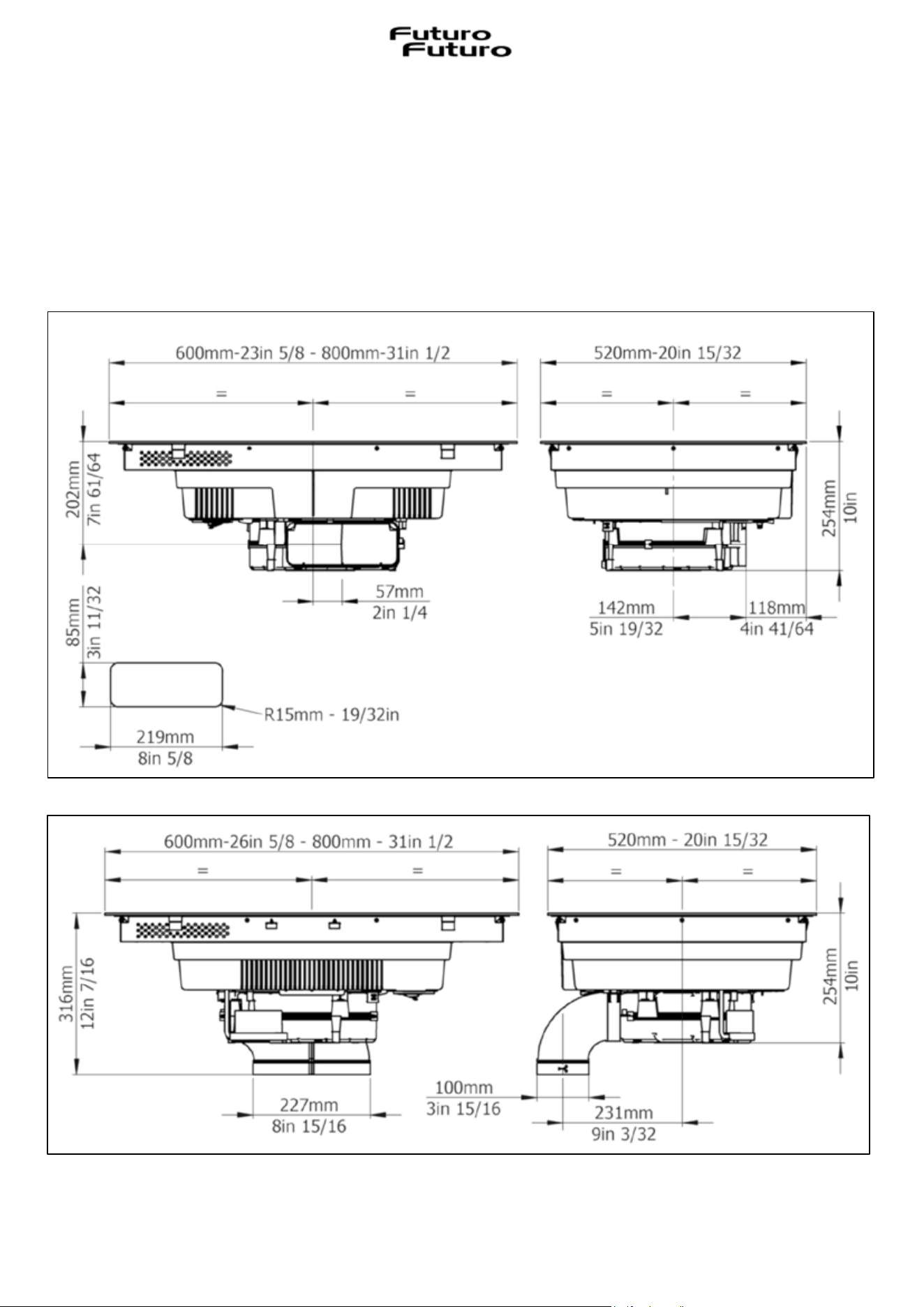
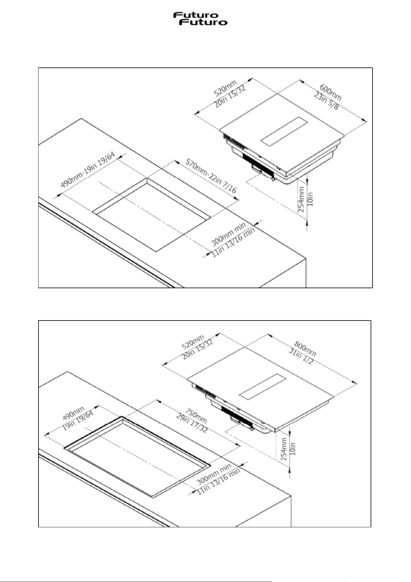
Attention: check the minimum dimensions of the unit for installation considering the overall
dimensions of the appliance indicated in Fig. 3.2.2 and Fig. 3.2.3.
Fig. 3.2.2
Fig. 3.2.3
12
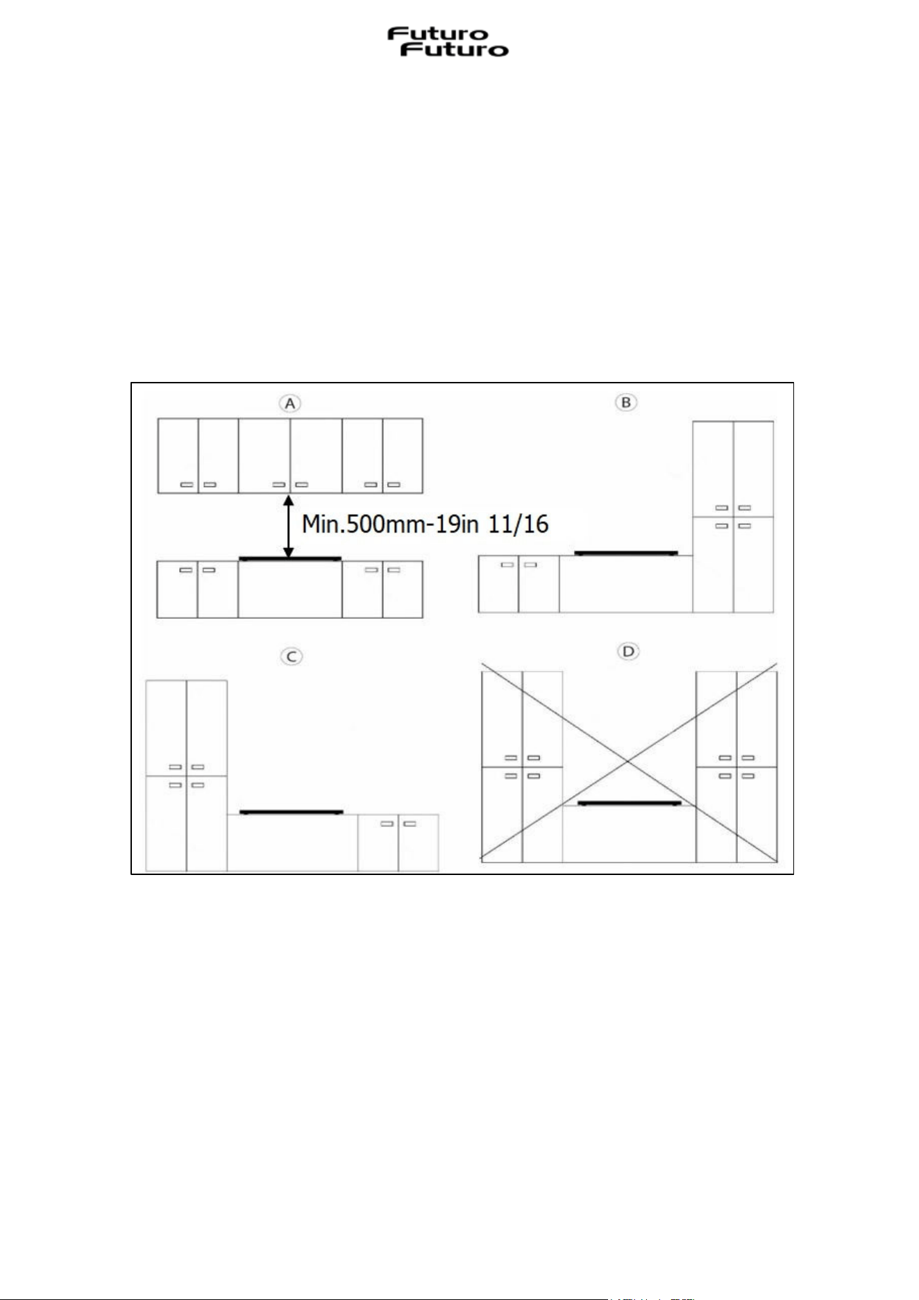
Fig. 3.2.4
The unit cladding must be treated with heat-resistant glues (100°C-212°F) otherwise, due to lower
thermal resistance, its shape and colour could change.
Ideally the appliance must be installed without tall units or walls on both sides (Fig.3.2.4-A). The
presence of tall units or walls is only permitted on one side of the appliance (Fig.3.2.4-B and
Fig.3.2.4-C). It is absolutely forbidden to place units or walls higher than the appliance on both
sides (Fig.3.2.4-D), for protection against the danger of fire. The use of wooden decorative slats
is not permitted.
We recommend installing the appliance only after having assembled the wall unit to avoid any
damage to the glass top.
The safety space between the hob and any unit positioned above it must respect a minimum
distance of 500 mm-19in 11/16. (Fig. 3.2.4-A).
13
III.3 INSTALLATION
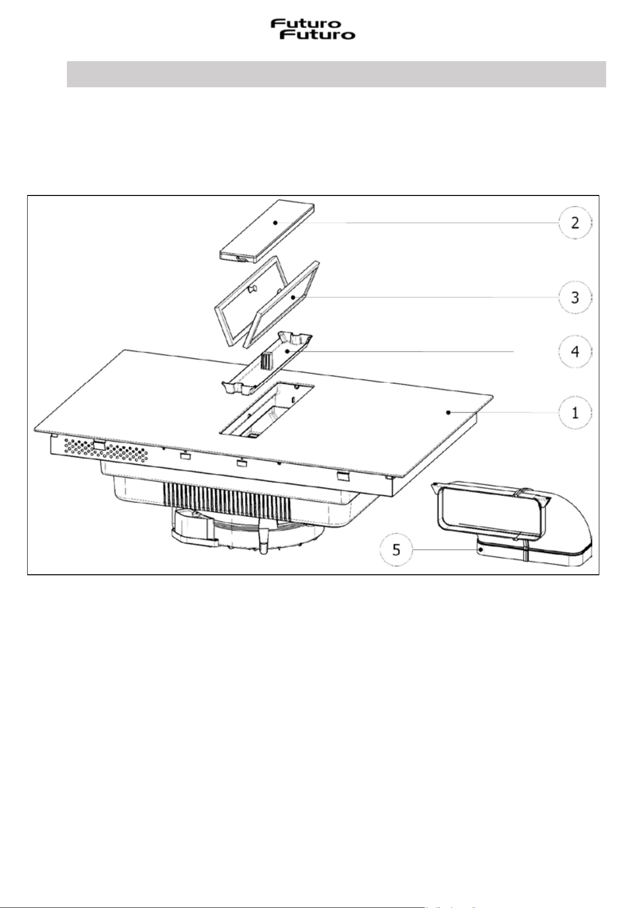
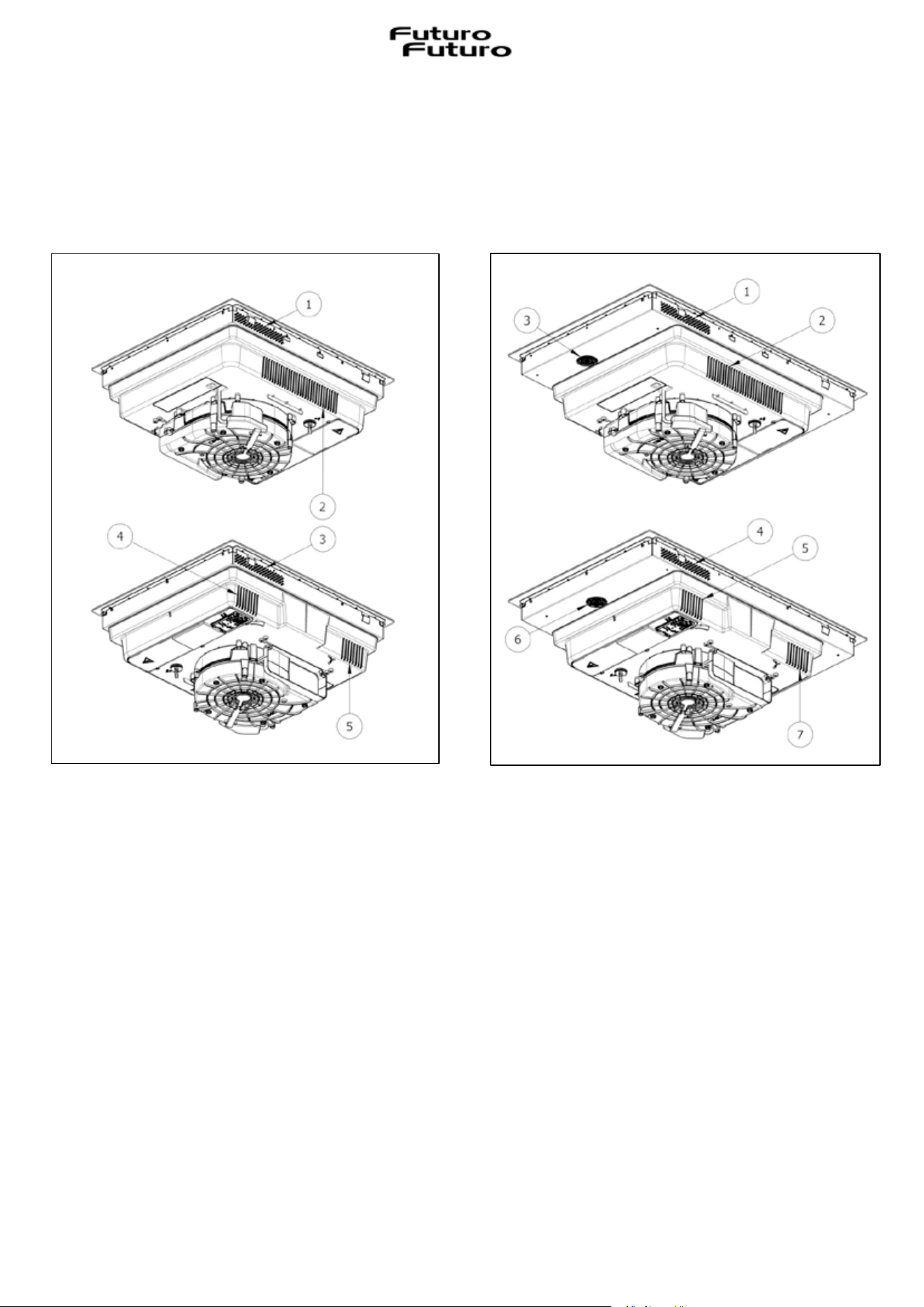
Upon opening the box, the installer will be presented with the elements shown below, to be
installed according to the method described in these pages.
Front view (Fig. 3.3.1):
1. Hob
2. Glass flap
3. Grease filters
4. Condensate collection tray
5. Air outlet fitting
Fig. 3.3.1
14
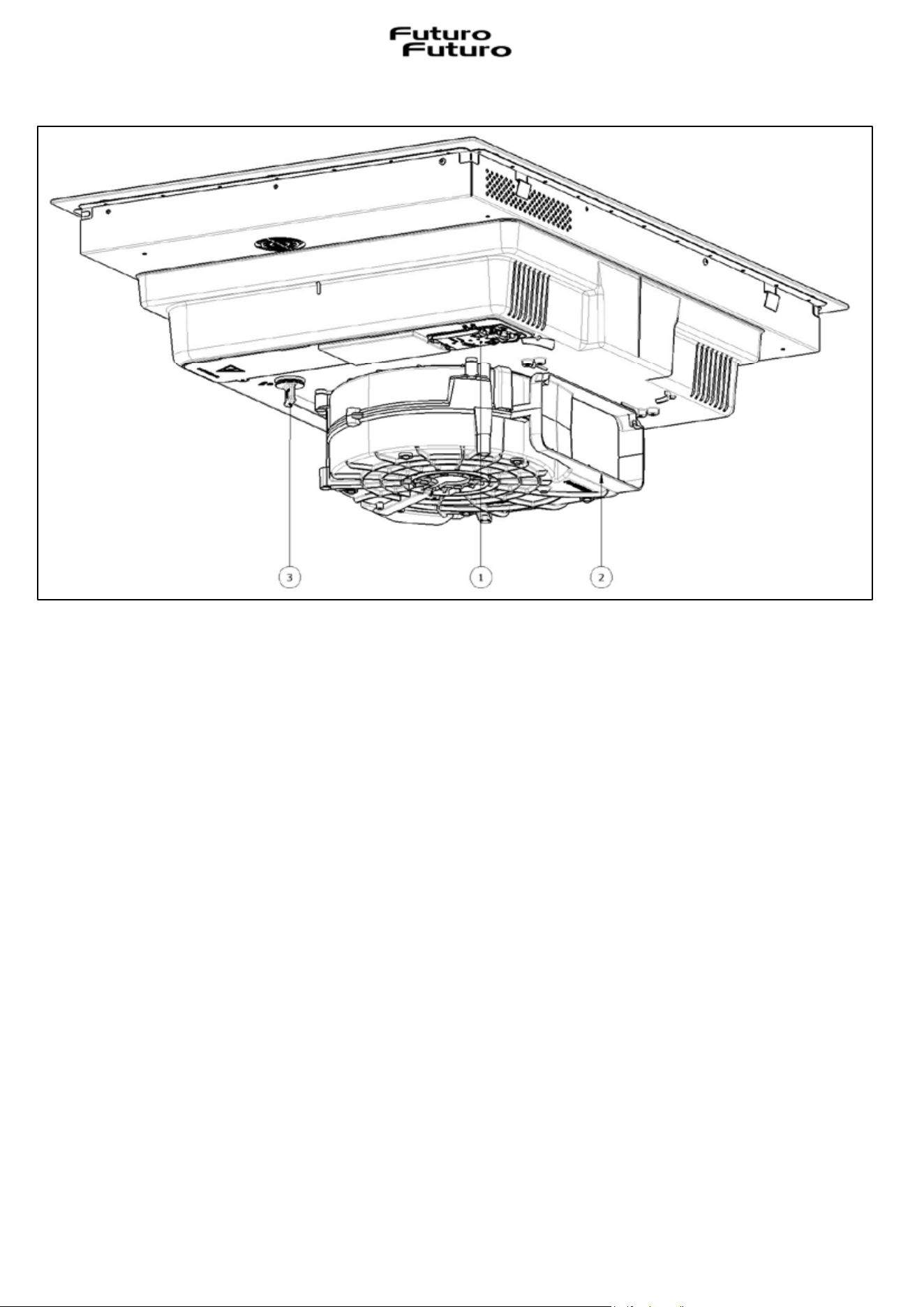
Rear view (Fig. 3.3.2):
1. Power box
2. Extractor outlet
3. Liquid drain plug
III.3.a INSTALLATION OF THE INDUCTION HOB
To leave the necessary space for the air pipe, it is important to install the induction hob with the
centre line more than 300mm-11in 13/16 away from any wall on the rear.
The induction hob can be installed in two ways either resting on the work surface or flush with the
work surface.
Fig. 3.3.2
15
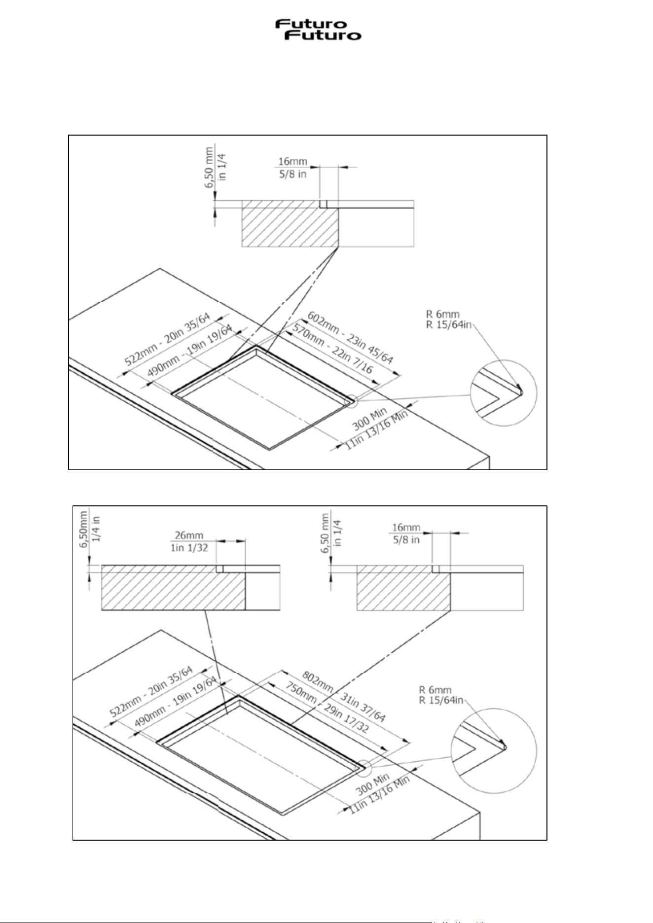
To perform LAY-ON INSTALLATION, drill the top as shown:
Fig. 3.3.a.1-A -> 60cm-23in 5/8 hob:
Fig. 3.3.a.1-B -> 80cm-31in 1/2 hob:
Fig. 3.3.a.1-
A
Fig. 3.3.a.1–B
16
To perform FLUSH INSTALLATION, drill and mill the work surface along the edge of the installation
hole, respecting the measurements indicated:
Fig. 3.3.a.2-A -> 60cm-23in 5/8 hob:
Fig. 3.3.a.2-B -> 80cm-31in 1/2 hob:
Fig. 3.3.a.2-B
Fig. 3.3.a.2-
A
17
The installation is under the sole responsibility of the specialists.
The installer is required to comply with the legislation and standards in force in their country of
origin.
Materials are often used to expand work surfaces in contact with water. To protect the cut edge of
the unit, apply a coat of varnish or special sealant. Particular care must be taken when applying
the adhesive seal supplied with the hob to prevent leaks in the support unit. This seal ensures a
proper seal when used in conjunction with smooth work surfaces.
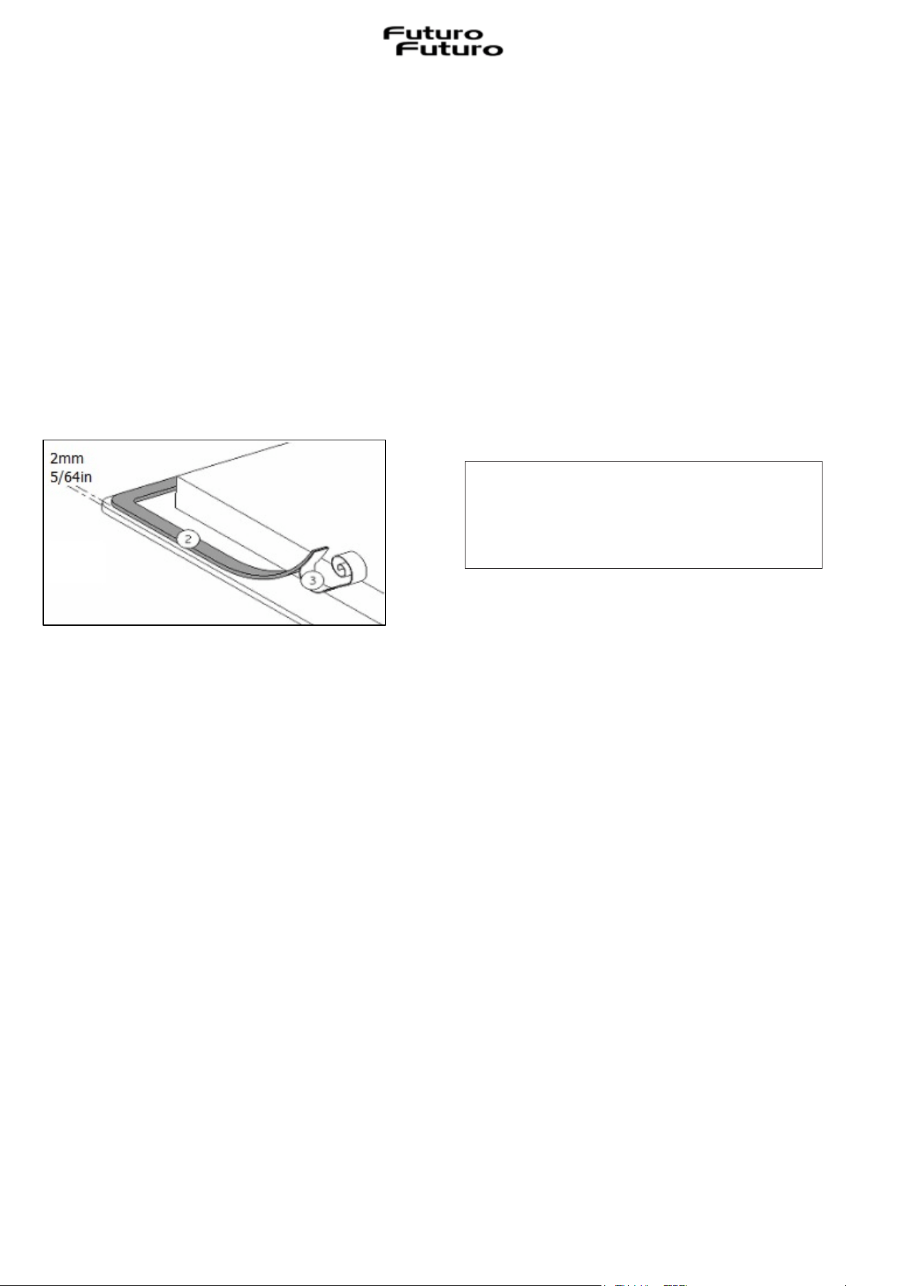
How to attach the seal:
The seal supplied with the hob prevents all liquid infiltration into the unit.
Its installation must be performed carefully, respecting the following drawing.
Attach the seal (2) two millimetres-
5/64in from the outer edge of the glass,
after removing the protective sheet (3).
Assembly - installation:
· Make sure there is a distance of 50mm-1in 31/32 between the hob and the wall or sides.
· Ideally the hob should be installed with plenty of space on both sides. There may be a wall to the
rear and tall units or a wall to one side. On the other side, however, no unit or divider should be
higher than the hob.
The unit or support into which the hob is to be installed, as well as the edges of the unit, the
laminate coverings and the glue used to fix them, must be able to withstand temperatures of up to
100°C-212°F.
· The edge wall rods must be heat-resistant.
· Do not install the hob above a non-ventilated oven or dishwasher.
18
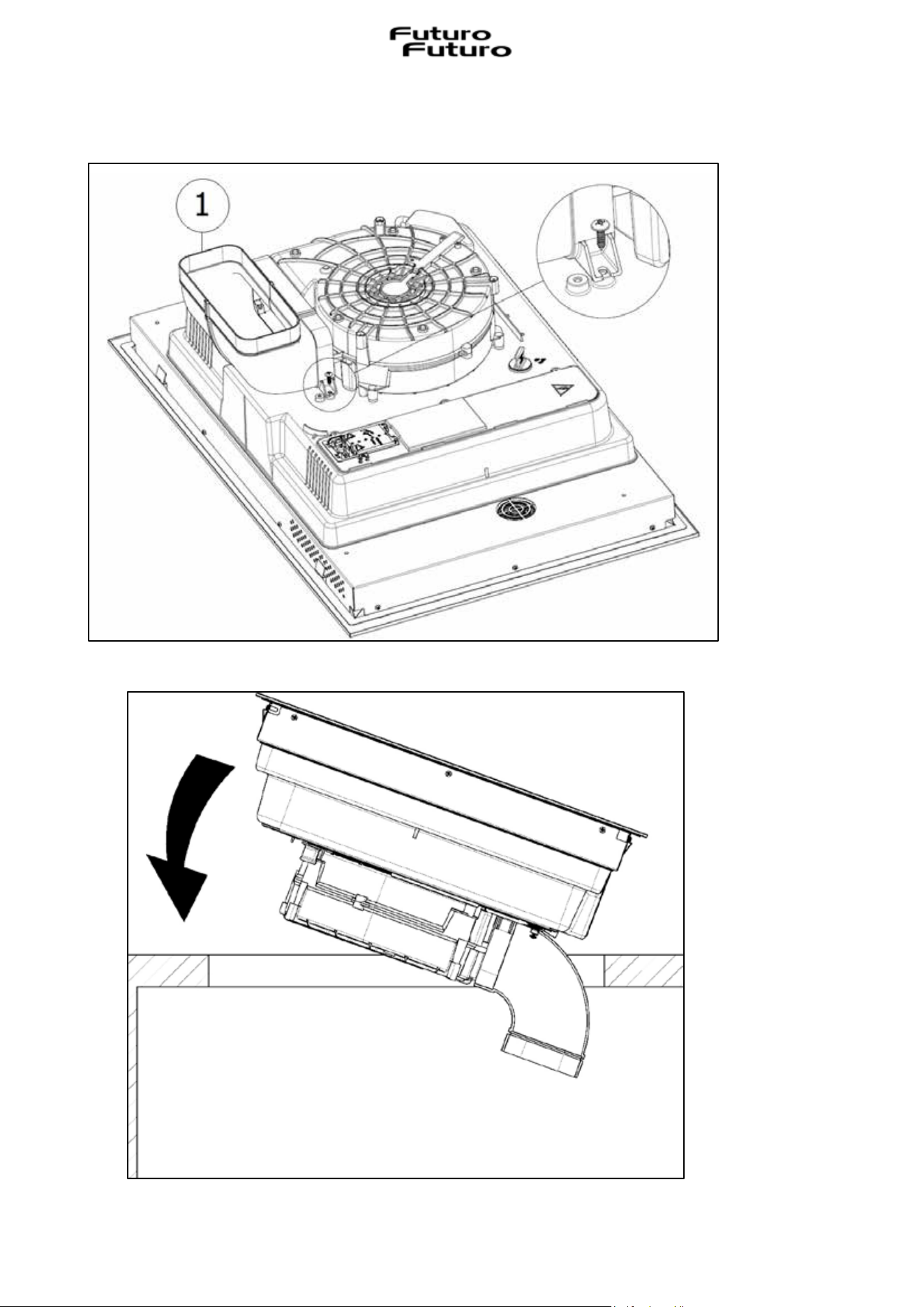
Attach the air fitting (Fig. 3.3.a.3-1) on the extractor outlet with the two screws supplied.
Support the hob (Fig.3.3.a.4)
Fig. 3.3.a.3
Fig. 3.3.a.4
19
It is necessary to ensure adequate ventilation on the front and rear of the unit, making sure that the air
is able to circulate through the various air intakes as indicated below in the figures:
Fig.3.3.a.5-A->60cm-23in 5/8 hob (5 air intakes) - Fig. 3.3.a.5-B->80cm-31in 1/2 hob (7 air intakes)
x If a drawer is under the hob, to ensure good air circulation and a good cooling system of the
appliance, maintain a space of at least 30mm-1in 3/16 between the ventilation of the lower part
of the hob and what is placed inside of the drawer.
x If a drawer is positioned under the hob, avoid placing flammable items (for example: sprays)
or non-heat resistant items in this drawer.
x After installation, the connection cable must not be subjected to any mechanical stress, such
as due to a drawer.
x WARNING: use only hob protections designed by the manufacturer of the cooking appliance or
indicated by the appliance manufacturer in the user instructions as suitable or hob protections
incorporated in the appliance. The use of inadequate protections can cause accidents.
Fig.3.3.a.5-
A
Fig.3.3.a.5-B
20
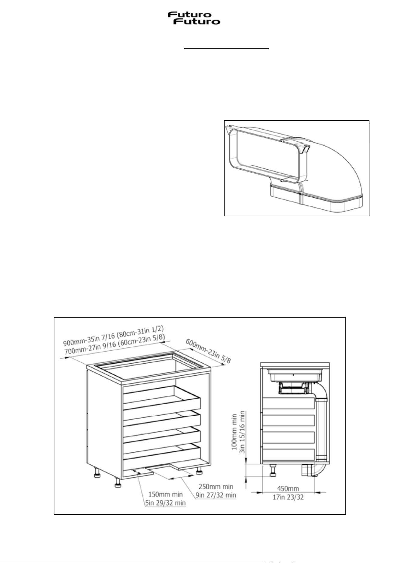
III.3.b CONSTRUCTION INSTRUCTIONS - OUTLET ON PLINTH
To convey the air into the plinth it is necessary to create a vertical pipe parallel to the back of the
unit. Appropriately sized accessories, pipes and fittings are available, please contact the
manufacturer.
In order to correctly make the coupling between
the extractor outlet (Fig. 3.3.2-2) and the pipe, use
the supplied accessory shown in Fig. 3.3.b.1.
To allow the vent pipe to be seated correctly, if it is provided under the plinth of the unit, the outlet
should be created in the base as shown in Fig. 3.3.b.2 and the rear panel possibly removed.
The introduction of this extraction system on a unit with a depth of 600mm-23in 5/8 implies a
maximum possible length for any drawers provided under the hob of approximately 450mm-17in
23/32. If the depth of the unit is greater, the underlying drawers will also have a wider length.
Fig. 3.3.b.2
Fig. 3.3.b.1
21
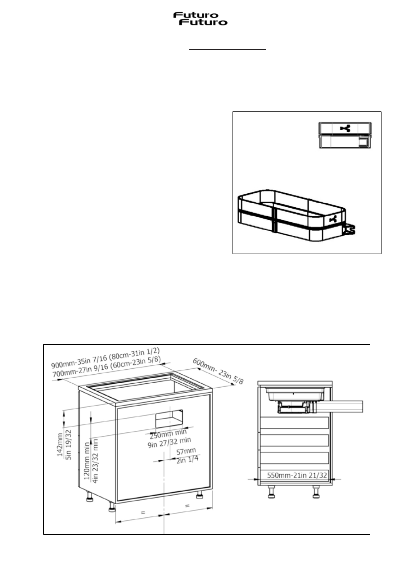
III.3.c CONSTRUCTION INSTRUCTIONS - REAR DISCHARGE
To convey the air to the rear, it is necessary to create a horizontal pipe perpendicular to the back
of the unit. Appropriately sized accessories, pipes and fittings are available, please contact the
manufacturer.
In order to correctly make the coupling between
the extractor outlet (Fig. 3.3.2-2) and the pipe, use
the supplied accessory shown in Fig. 3.3.c.1.
To allow air to be vented to the rear, the outlet should not be created on the base of the unit.
The outlet should be created through the rear panel as indicated in Fig. 3.3.c.2 or the latter possibly
removed.
On a unit with a depth of 600mm-23in 5/8, the maximum possible length for any drawers provided
under the hob is approximately 550mm-21in 21/32. If the depth of the unit is greater the underlying
drawers will also have a wider length.
Fig. 3.3.c.2
Fig. 3.3.c.1
22
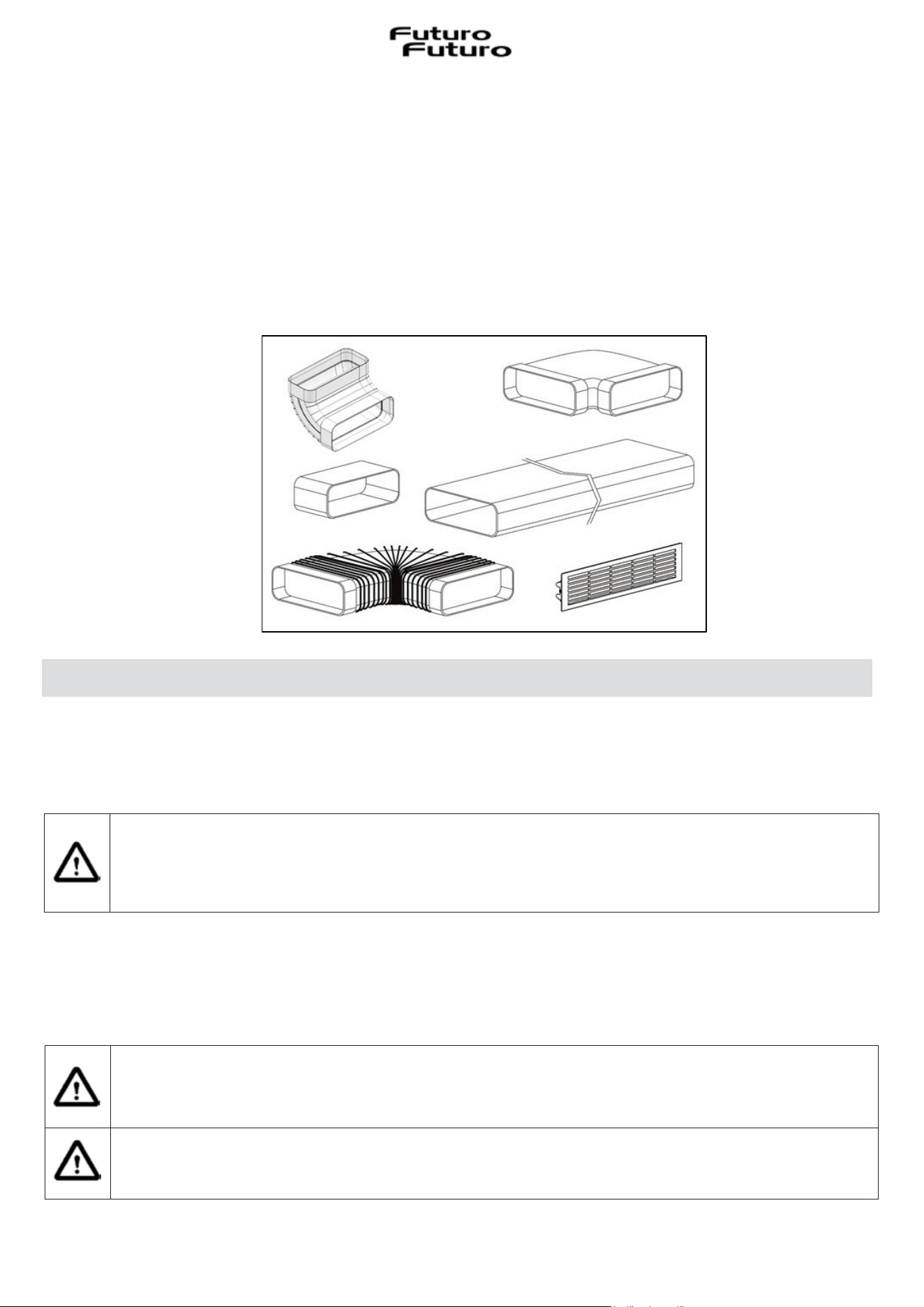
III.3.d ASSEMBLING THE AIR VENTING PIPE
To bring the air outlet to the desired position, it will be necessary to install the pipe using fittings
that can be purchased separately (Fig. 3.3.d.1).
To purchase these accessories, ask the manufacturer for them.
The entire pipe must necessarily pass under the base of the unit, in the space of the plinth riser.
Our accessories also allow the installation of filtering kits.
III.4 ELECTRICAL CONNECTION
The electrical connection must ONLY be performed by specialist technicians.
The electrical protection of the electrical connection upstream of the appliance must comply with
the standards in force.
Attention! Make sure that the voltage (V) and frequency (Hz) indicated on the serial
number plate inside the appliances correspond to those available in the place of
installation.
Any modifications that may be necessary to the electrical system to install the appliance must only
be performed by competent persons.
After installation, the insulated parts and those carrying electric current must be protected from
possible contact.
Attention! If the electrical connection is performed incorrectly or not according to
the standards, parts of the appliance can be damaged and the warranty will be
invalidated.
Attention! Before any intervention, disconnect the appliance from the mains (Fig.2.1-
Fig. 2.2 WARNINGS chapter).
Fig. 3.3.d.1
23
These appliances must be connected to an earthed system.
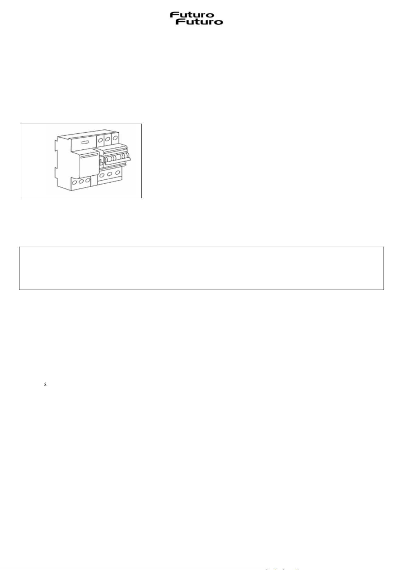
The appliance must be connected to the electrical mains system, interposing an omnipolar switch
which ensures disconnection from the network, with an opening distance of the contacts which
allows complete disconnection under the conditions of overvoltage category III, in compliance with
the installation rules (Fig.3.4.1).
The earth connection (yellow-green cable) must never be interrupted.
The power cable must be long enough to allow connection of the appliance, built into the appliance,
to the mains. If the power cable is damaged, it must be replaced in order to prevent any risk.
Protection against live parts must be ensured after installation.
Connection to the mains must be made using an earthed plug or an omnipolar circuit breaker
device with a contact opening of at least 3mm-1/8in.
The power cable must be positioned in such a way as not to touch the hot parts of the hob or
anything else.
To connect the appliance to the mains, use a power cable with a minimum conductor section of
2,5mmϡ– 0,0038in² for power up to 7360 Watt.
At no point should the cable reach a temperature 50°C-122°F higher than ambient temperature.
We cannot be held responsible for any accidents resulting from incorrect connection or which
may arise from using an appliance which has not been earthed or which has been fitted with
a faulty earth connection.
Fig. 3.4.1
24
The appliance is intended to be permanently connected to the electricity mains.
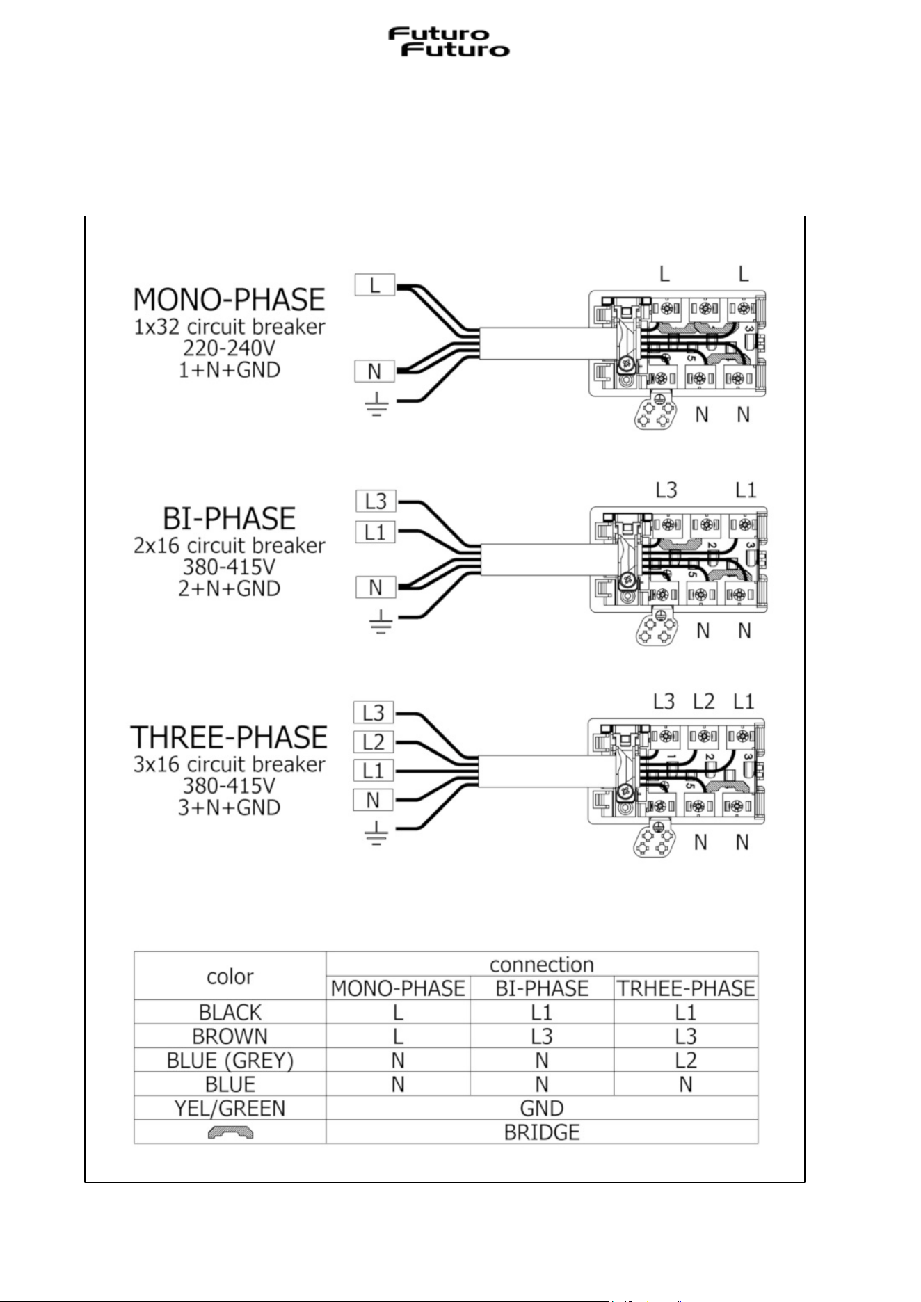
Attention! Comply with the following connection diagram (Fig. 3.4.2):
Fig. 3.4.2
25
IV OPERATION
IV.1 DESCRIPTION OF THE EXTRACTING INDUCTION HOB
IV.1.a TECHNICAL CHARACTERISTICS
Parameters Value
Polyphase connection voltage 380 – 415V 2N / 3N
Single-phase connection voltage 220 – 240V
Frequency 50Hz / 60Hz
Max power consumed
7.4 kW
Adjustable power,
see on HOB CONFIGURATION,
User menu
Fuse / connection to the three-phase network 3 x 16A
Fuse / connection to the two-phase network 2 x 16A
Fuse / single-phase mains connection 1 x 32A
Dimensions (width x depth x height) 60 cm -> 600mm x 520mm x 254mm
23in 5/8 -> 23in 5/8 x 20in 15/32 x 10in
80 cm -> 800mm x 520mm x 254mm
31in 1/2 -> 31in 1/2 x 20in 15/32 x 10in
Net weight (hob only) 60 cm -> 19,0 kg / 80cm -> 20,0 kg
23in 5/8 -> 41,88lbs / 31in 1/2 -> 44,09lbs
Gross weight (including packaging) 60 cm -> 27,5 kg / 80cm -> 29,5 kg
23in 5/8 -> 60,62lbs / 31in 1/2 -> 65,03lbs
Hob
Surface material Glass ceramic
Power level 1 - 9, P
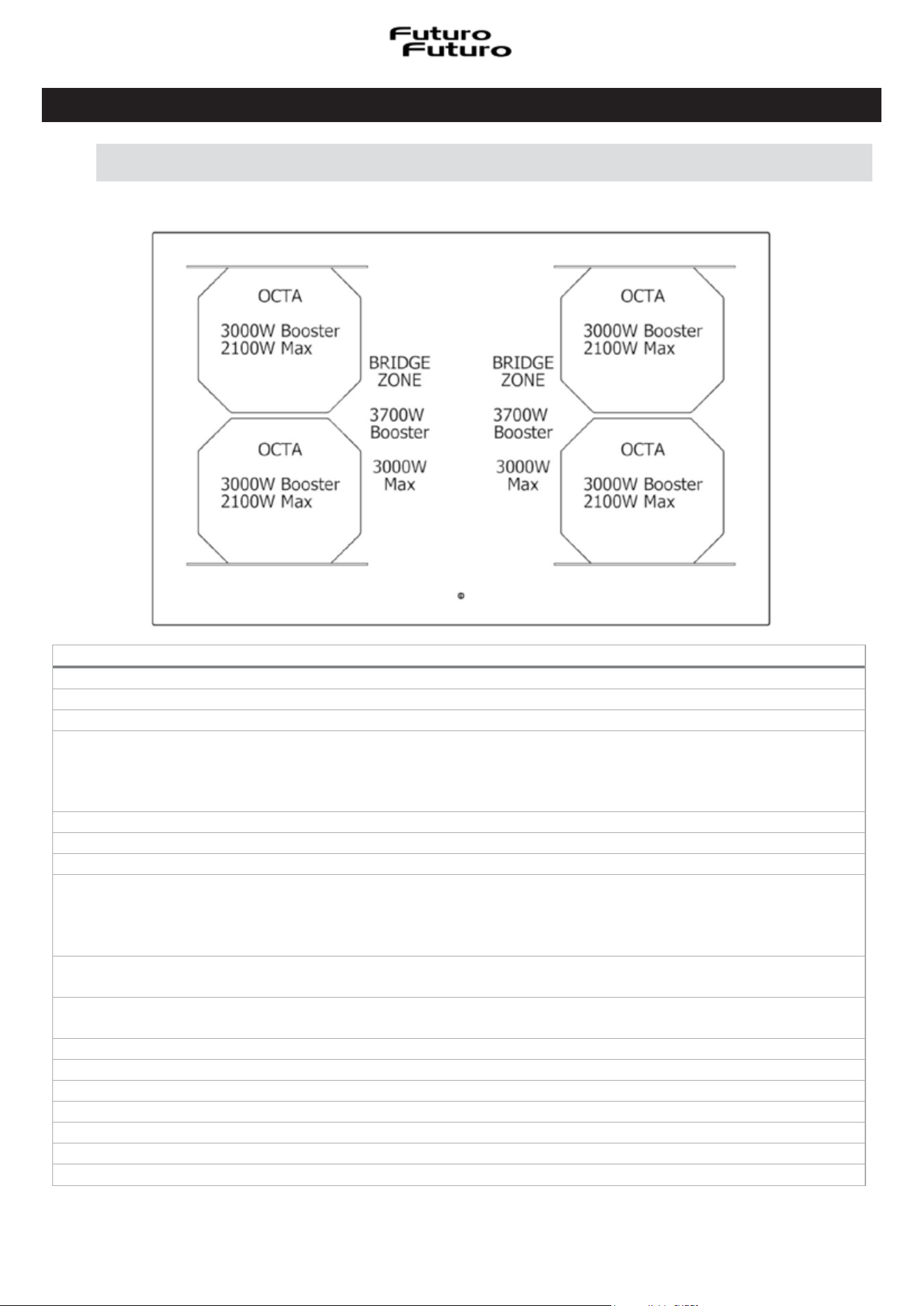
Cooking zone dimensions OCTA 210mm x 190mm (8in 17/64 x 7in 31/64)
Max-booster cooking zone power level 2100W - 3000W
Extraction system
Power level 1 - 9, P
26
IV.1.b MAIN CONTROL CHARACTERISTICS OF THE EXTRACTOR HOB
CONTROL PANEL (TOUCH CONTROL “TC”)
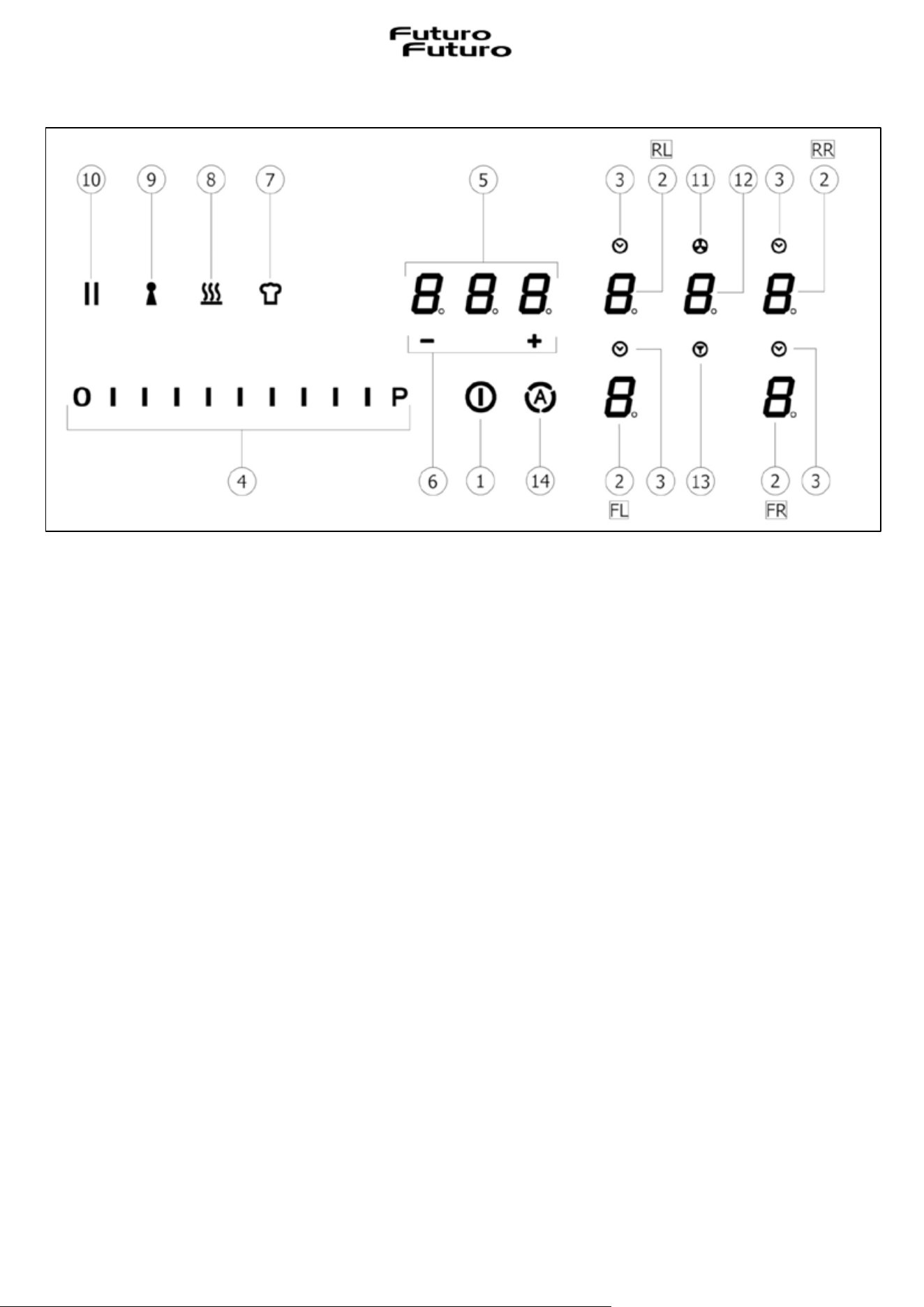
Touch keys (Touch) / Display
1. ON/OFF of the hob/extractor system
2. Cooking zone selection / Cooking zone display:
2FL ї Front Left
2FR ї Front Right
2RL ї Rear Left
2RR ї Rear Right
3. Cooking zone timer activation / Active cooking zone timer indicator
4. Increase/Decrease cooking power level and extraction speed (power) /
Display of cooking power level and suction speed (power)
5. Activation of Independent Timer / Independent Timer Display / Cooking zone timer display
6. Independent Timer time increase/decrease / Cooking zone timer display
7. Activation of the "Chef cook" function
8. "Warming" function activation
9. "Keylock" function activation
10. "Pause" function activation
11. Active extractor indicator
12. Selection/activation of extractor / Extractor display
Long life ceramic odour filter saturation – grease filter display
13. Filter saturation reset
14. Activation of extractor automatic function
27
IV.2 CONTAINERS FOR COOKING
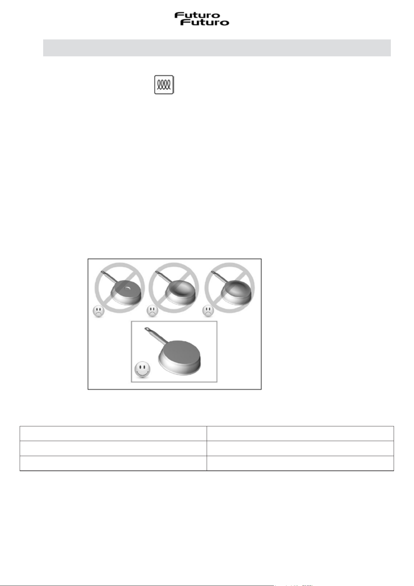
IV.2.a QUALITY OF THE PANS
Only use pans bearing the symbol
Suitable materials: steel, enamelled steel, cast iron, ferromagnetic stainless steel, aluminium with
a ferromagnetic base.
Unsuitable materials: aluminium and stainless steel without ferromagnetic base, copper, brass,
glass, ceramic, porcelain.
Manufacturers specify whether their products are induction compatible.
To check if the pans are compatible:
· Add some water to a pot positioned on an induction heating zone set to the minimum level. This
water must heat up in seconds.
· A magnet sticks to the bottom of the pot.
Some cookware can make noise when placed on an induction cooking zone. This noise does not mean
that there is a fault with the appliance and it will not affect the cooking operation.
IV.2.b DIMENSIONS OF PANS
The minimum recommended diameter of the pans to be used is:
Function active Minimum pot diameter
Single cooking area Ø 110mm – 4in 21/64
“Bridge” cooking zone Ø 230mm – 9in 1/16
The bottom of the pot must never touch the central glass flap.
To obtain the best efficiency of the hob, position the suitable pot well centred in relation to the
cooking zone marked on the glass ceramic surface.
28
IV.3 INDUCTION HOB
Important:
All functions of this hob are designed to comply with the most stringent safety regulations.
For this reason:
• Some functions are not activated, or are deactivated automatically, if there are no pans on the
burners or when they are incorrectly positioned.
• In other cases the activated functions will be automatically deactivated after a few seconds, if the
specific function requires a further setting that has not been selected (e.g.: “Turn the hob on”
without “Selecting the cooking zone” and the “Operating temperature”, or the “Lock Function” or
the “Timer” function).
Attention! In the case (for example) of prolonged use, the cooking zone may not immediately shut
down because it is in the cooling phase; the “H” symbol will appear on the cooking zone display, to
indicate the execution of this phase.
Wait for the display to switch off before approaching the cooking zone.
IV.3.a COOKING ZONE DISPLAY
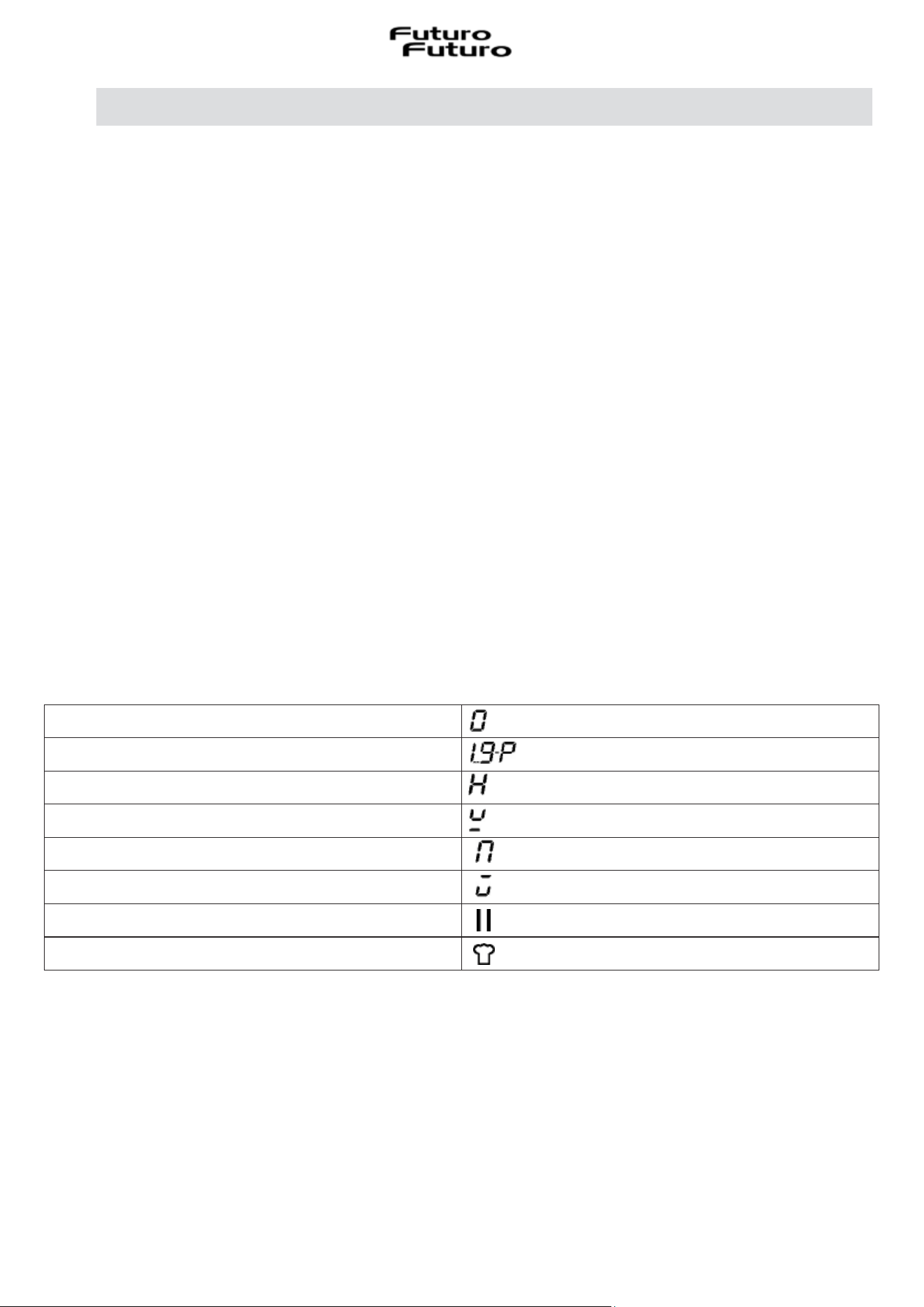
The following is shown on the cooking zone displays:
Cooking zone on
Power level (P=Power Booster)
Residual heat display
Pot Detection
Bridge function active
Warming function active
Pause function
Chef Cook Function
29
IV.3.b HOB CHARACTERISTICS
¾ Permanent Pot Detection:
The hob is only activated in the presence of pots on the cooking zones. Heating does not start, or
stops, if pots are absent or removed.
¾ Pot Detector:
The hob automatically detects the presence of pots on the cooking zones.
¾ Safety Shutdown:
For safety reasons, each cooking zone has a maximum operating time which depends on the power
level set.
¾ Residual Heat Indicator:
When one or more cooking zones shut down, the presence of residual heat is indicated by a visual
signal on the corresponding zone display, by way of the “H” symbol.
¾ Acoustic feedback (Beep)
Function activation acoustic signal
IV.3.c HOB CONFIGURATION
Before use, the Touch Control Panel of the hob, it must be set up to suit your personal requirements.
When the hob is powered, the symbol will flash for 2 minutes to indicate that it is possible to
access the user menu. Wait for it to switch off and for all the functions to be active according to the
factory settings.
¾ USERMENU
From the user menu it is possible to modify certain functions of the control panel such as the
brightness, the volume of the sound of the keys, the volume of the information sounds, the lighting
of the control panel, the animation of the timer, etc.
To access the User Menu, the control panel (hob control display) must be in standby mode (off).
User Menu Access:
-> Touch ON/OFF to turn on the Control Panel, then touch ON/OFF again within 3 seconds to turn
off.
-> The || key (Pause) starts pulsing for a maximum of 60 seconds (if no action is taken, the attempt
to enter the menu is automatically exited after these 60 seconds).
-> Press the || key (pause) without releasing it.
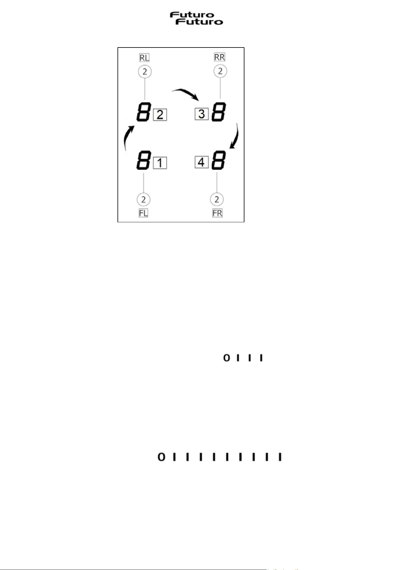
-> Press the display of each cooking zone clockwise as shown in Fig. 4.3.c.1, again without releasing
the Pause key, starting from the display of the left front cooking zone 2FL (1-2-3-4).
30
-> Each key press will be confirmed by an acoustic signal (beep).
-> Release the || key (pause) that pulsed.
-> The user menu is active.
-> The rear left cooking zone display (2RL) flashes “U0” (“U” and “0”).
-> Select the menu item to be viewed/modified using the slider (4) as summarised in the table Fig.
4.3.c.2.
For example, to go to U4 (display brightness), press 2RL on the display and select level 4 with the
touch slider (the third slider bar starting from the left)
Now therefore U4 flashes intermittently.
-> At this point the left front display (2FL) is selected where the set value and any variation
possibilities are displayed.
In the example of the brightness setting, after having selected the left front display (2FL), all the
bars up to 9 will appear on the slider and the number will appear on the display (2FL) with a
permitted value, in this case from 0 to 9 (in other cases there may be fewer values, for example in
U3 there are only values from 0 to 3)
Then the selected value of the corresponding selected element is shown on the display of the front
left cooking zone (2FL), after which change the value by touching the slider.
Fig. 4.3.c.1
31
Exiting from the User Menu:
-> Exit without saving: Touch the || key (Pause).
All changes are discarded and the || key stops flashing.
-> Exit with Save settings: Touch the power ON/OFF key for 2 seconds.
The changes are saved and the || key stops flashing.
Note: The user menu exits automatically if no operation is performed for 1 minute.
Overview of the user menu items
The following table (Fig. 4.3.c.2) provides an overview of the user menu items:
Display
Rear
Left
(2RL)
Meaning Display
Front
Left
(2FL)
Note
U0 Power regulation
range
Adjustable
from >1.4kW
upwards
with 0.1 kW
step
Maximum configured power
by default: Value 0 -> 7.4 kW
(Value X->X.X kW if otherwise configured during
installation via Service Menu)
1st step, select timer central display (5)
where the set power value is lit up (for
example 7.4);
2nd step, scroll with the slider (4):
-> from left to right to raise the value
-> from right to left to lower the value
U1 Filter Setting:
Grease filter or Odour
filter with or without
5-minute Adjustable
and Delayed self-
switching Off (it is an
extraction function at
level 1 after the hob
has been switched off
cooking is completed)
0,1,2,3 Default Filter setting -> 0
0: Grease filter
with Adjustable and Delayed
self-switching Off 5 minutes
1: Grease filter and odour filter
with Adjustable and Delayed
self-switching Off 5 minutes
2: Grease filter
without Adjustable and Delayed
self-switching Off
3: Grease filter and odour filter
without Adjustable and Delayed
self-switching Off
U2 Volume for button
tones
0,1,2,3 Volume adjustment for button tones:
0: No button tone
1: minimum volume
2: half volume
3: maximum volume (default)
Notes:
• For regulatory reasons, the button tones
for power on and off cannot be disabled.
They will sound at the last volume level that
was set before disabling the button tones.
• Error tones are always played at maximum
volume (setting 3) and cannot be disabled.
Fig. 4.3.c.2
32
U3 Volume for signal
tones
0,1,2,3 Adjusting the volume of the acoustic signals
(e.g. when the timer expires):
0: No button tone
1: minimum volume
2: half volume
3: maximum volume (default)
U4 Display brightness 0,1,2,3,4,5,6,7,8,
9
Display brightness adjustment:
0: maximum brightness (default)
....
9: minimum brightness
U5 Timer animation 0,1 0: No timer animation
1: The timer is animated 10 minutes before
it expires (default)
U6 Permanent pot
detection
Cannot be deactivated
U7 Behaviour when the
Timer expires
0,1,2 0: Acoustic signal for 120 sec. (default)
1: Acoustic signal for 10 sec.
2: No tone
IV.3.d HOB OPERATION
Before selecting any function, it is necessary to activate the desired zone.
¾ Switch-on/off
The extractor hob is turned on by touching the ON/OFF key (1) for a few seconds.
The symbol will light up
By keeping this key pressed, all the available functions will become visible for a few moments, then
only the main functions will remain active.
While using the hob, the other functions will also be activated and can be used.
All the available functions will be illuminated with low intensity, which will only increase when they
are activated.
To switch off, touch the ON/OFF key (1) for a few seconds.
Important: This function has priority over all the others, therefore it is possible to switch off the
hob at any time.
The hob switches off automatically after 20 seconds if all the cooking levels are set to 0 and no
operation is in progress.
¾ Selection of cooking zones
Touch the Selection/Display area (2) corresponding to the desired cooking zone.
33
¾ Power level: increase/decrease
The hob is equipped with 9 power levels.
Touch and slide your fingers along the Selection Bar (4) to increase or decrease:
ї to the right to increase the power level;
і to the left to decrease the power level.
The power level set will be displayed in the Selection/Display area (2)
¾ "P" Booster Function (Enhanced Level)
The hob is equipped with an additional power level (Booster, in addition to level 9) which remains
active for 5 minutes and then the power returns to the lower level (9).
This function is useful for heating or boiling a large quantity of water.
To activate the Booster function, slide with your fingers along the selection bar (4), beyond level 9
and activate the Booster function. The “P” symbol will appear on the Display (2).
By activating the Booster (P) on two cooking zones on the same side (2FL+2RL or 2FR+2RR) the first
zone of the two activated will automatically switch to lower power to balance the maximum power
permitted for each side. To change the cooking zone on which to leave the Booster active, simply
select it and take it to level P; the other will automatically be brought to lower power.
Attention: since the Booster function can reach high temperatures, it must only be used for cooking
with the use of water. Oil or fat may start burning if the booster function is used.
¾ Key Lock function
The Key Lock function blocks the hob settings, to prevent accidental tampering, leaving the functions
already set active.
To activate it, touch the key (9); to deactivate it, press the same key again.
If any other function is selected while Key Lock is active, the symbol will remain on a steady light
to indicate that the function is active. Then deactivate the function to be able to act on the hob.
¾ Child Lock function
The Childproof lock is a feature to protect the hob from undesirable operations, for example by
children. If it is locked, the hob can be switched on, but it is not possible to select the cooking zone,
neither the heating level nor the timer. The cooking zone displays will show the symbol
The childproof lock can only be activated once after switching on. Once activated and deactivated,
the child lock cannot be activated a second time. Only after switching ON/OFF can the childproof
lock be activated again.
The childproof lock remains active even if the supply voltage is interrupted and recovered. It must
be deactivated manually.
34
Activation:
-> Switch on the hob (Key 1).
-> Press and hold the display of any cooking zone (2) for 3 seconds. Then release the Display.
-> The scroll bar (4) lights up sequentially.
-> Slide the slider cursor from 0 to 9 within 10 seconds.
-> The childproof lock is activated. All the cooking zone displays show
Deactivation:
-> Switch on the hob (Key 1).
-> Press and hold the display of any cooking zone (2) for 3 seconds. Then release the display.
-> The scroll bar (4) lights up sequentially.
Slide the slider cursor from 9 to 0 within 10 seconds.
The childproof lock is deactivated. The hob switches to operating mode and can be operated
normally.
¾ Chef Cook Function
The Chef Cook function is used to set different cooking levels in the cooking zones.
The following power levels are set and dissipated as soon as a suitable pot is placed on the cooking
zones:
Rear left cooking zone ->(2RL): Level 5 - Rear right cooking zone ->(2RR): Level 6
Front left cooking zone ->(2FL): Level 2 - Front right cooking zone ->(2FR): Level 8
To start the Chef Cook function, as soon as the hob is switched on, it is first necessary to activate at
least one cooking zone at any power. Subsequently, the function can be activated and deactivated
at any time, until the hob is switched off.
Notes:
The power levels cannot be set by the user.
The operating time limit for the Chef Cook function is 2 hours.
While the Chef Cook function is active, the "pot detection" symbol is removed.
While the Chef Cook function is active, the Bridge function cannot be activated.
35
Activation:
-> The hob is switched on.
-> Touch the Chef Cook function key (7).
-> The Chef Cook mode is activated.
-> The cooking zone displays (2) show the set power levels:
2RL -> 5 - 2RR -> 6
2FL -> 2 - 2FR -> 8
Deactivation:
-> Touch the Chef Cook function key (7).
-> The Chef Cook mode is deactivated.
-> The power levels for all the cooking zones are set to 0.
¾ Automatic Heat-Up function (Rapid heating)
This function is used to reheat a cold pot with full heating power and to automatically return to the
desired cooking level. It will therefore be possible to cook faster without the risk of burning the
food. The function can be activated for power levels from 1 to 8.
The time to reach full power in the cooking zone depends on the cooking level selected and
mentioned in the table below. The heating times are adapted for use with cold pots and common
household food quantities.
Cookin
g
level Heat-U
p
Time
(
seconds
)
1 48
2 144
3 230
4 312
5 408
6 120
7 168
8 216
9 Not available
P Not available
Activation:
The pots are positioned and the hob is active with a level of between 1 and 8 for the cooking zone
(2). Select the cooking zone concerned.
Touch and hold the cooking level on the selection bar (4) for 3 seconds.
On the Display (2) a flashing appears which alternates with the power set in the cooking zone.
By increasing the power level of the cooking zone, the Heat-Up function remains active, with the
new temperature setting;
By decreasing the power level of the cooking zone, the Heat-Up function is deactivated.
36
Deactivation:
Touch and hold the cooking zone (2) for 3 seconds.
Rapid heating is deactivated and the cooking zone is heated with the previously set cooking level.
Alternative: Select a cooking level lower than the level currently set for this cooking zone. Rapid
heating is deactivated. The cooking zone is heated up with the new cooking level.
¾ Warming function (Keeping warm)
This function keeps cooked food warm at a constant temperature.
The function is activated when the key (8) is pressed for the first time.
The symbol appears on the display (2) of the zone that is working with the "Warming" function
active.
By selecting another cooking zone at the same time, the symbol (8) will once again have a dim
light, and it will therefore be possible to activate the function for this zone as well. However, the
function remains active in the zone in which it has already been set, as indicated on the Display (2).
Press the key (8) again to deactivate and switch off, until bringing the level shown on the display
(2) to 0.
If the "Warming" function is active on several cooking zones, first select the desired zone using the
Selection Display (2). This function can also be deactivated via the Selection
Bar (4), bringing the Power level to 0.
¾ Pause function
The Pause function suspends any active function on the hob, bringing the cooking power to 0.
To activate the function, press ||(Pause, 10) and the cooking zone displays (2) will show a steady
light
To deactivate the function, press || (Pause, 10), tap the Selection Bar (4) and the function will
deactivate.
Deactivation restores the conditions of the hob before the pause and the hob continues to work with
the same settings previously set.
Attention: the hob must never be left unattended while the pause function is active.
10 minutes after activation of the Pause Function, if it is not deactivated, the hob switches off
automatically.
The Pause Function does not suspend extraction.
37
¾ Recall Function
This function is used to recover the power levels, timer settings and rapid heating after the hob has
been switched off inadvertently.
If the hob is switched off and on again within 6 seconds, all the previous settings (power levels,
timer, rapid heating) will be recovered automatically.
The recall function cannot be deactivated by the user.
Activation:
The hob has been switched off.
Turn the hob on again using ON/OFF (1).
The Pause key || (10) flashes for 6 seconds.
Touch the Pause || key (10).
The recall function becomes active (an acoustic “beep” is emitted). All the previously set power
levels, timers and rapid heating are restored.
¾ Autonomous Timer Function
The independent Timer function is a countdown independent of the cooking zones and extraction
which emits an acoustic signal (beep) when it expires.
The Timer is activated by pressing the central key (5) between the two + / - keys (6).
When the Display shows “–--" then the Timer can be set.
Set the desired duration of the timer using the + / - keys (6) and it will be shown on the display (5).
The timer starts 10 seconds after activating this function (by not pressing any other command).
The format of the autonomous Timer is
The timer can be set up to a maximum of 600 minutes.
The remaining time will be displayed in the Zone/Display (5); at the end of the countdown an
acoustic signal (beep) will be emitted.
If the remaining time of the timer is less than 1 minute, it will be displayed in the format shown
below and the dot will have a steady light:
-> minutes
-> seconds
To turn off the Timer, proceed in two ways:
-> select (5) and set the duration of the Timer to , using + / - (6)
or
-> press the ON/OFF key (1) twice
38
¾ Cooking zone timer
On each cooking zone, even simultaneously, it is possible to set the Cooking Zone Timer function
which is a countdown.
At the end of which the cooking zones switch off automatically, emitting an acoustic signal (beep).
To activate the function:
-> touch the Selection/Display area (2) with a power level other than 0
-> touch the key (3) relating to the cooking zone
-> the display shows “---“ and the Timer can be set.
-> set the duration of the timer, with the + / - keys (6), which is displayed in the Display area (5)
During programming the symbol (3) flashes.
The cooking zone timer starts 10 seconds after activation (without pressing any other key).
To reset the timer with cooking, press and hold the key (3) again
If desired, the Timer programming can be repeated for several cooking zones.
Each cooking zone can have a different Timer set and the display (5) will show the countdown of the
cooking zone selected at that moment.
If no zone is selected, pressing on the Display (5) the countdown of the Autonomous Timer is
displayed.
The countdown display is the same as for the Autonomous Timer (see previous paragraph)
At the end of the countdown, an acoustic signal (beep) will be emitted and the cooking zone will
switch off.
To stop the beep, press ON, or
To deactivate the Timer:
-> select the cooking zone (2) and set the duration of the Timer to with the + / - keys (6)
¾ Bridge Function
This function allows both cooking zones to work at the same time forming a single cooking zone with
the same power level.
This function allows homogeneous cooking with large pots.
The front "Primary" cooking zone can be used in combination with the corresponding "Secondary" one
at the back.
The function is provided on all cooking zones:
2FL (primary) + 2RL (secondary)
2FR (primary) + 2RR (secondary)
39
Bridge Function Activation:
-> select the two cooking zones to be used at the same time
-> on the Display (2) of the "Secondary" cooking zone the symbol " " appears
-> using the selection bar (4) it will be possible to set the operating level (power), which will be
shown on the display (2) of the "Main" cooking zone
Deactivate the Bridge Function:
-> repeat the same activation procedure
Attention: during the Bridge Function, the cooking zones are considered a single cooking area and
therefore, if the Cooking Zone Timer is active, when it expires it will cause both cooking zones to
switch off automatically.
¾ Power table
Power Level Cooking type Recommended use
Maximum
Booster
Quick heating
Ideal to quickly raise the temperature of food up to rapid
boiling in the case of water or to quickly heat cooking
liquids
8-9
Frying, boiling
Ideal for browning, starting cooking, frying frozen products,
boiling quickly
High
7-8
Browning, frying, boiling,
grilling
Ideal for frying, maintaining a lively boil, cooking and grilling
(for a short time, 5-10 minutes)
6-7
Browning, cooking, stewing,
frying, grilling
Ideal for frying, maintaining a light boil, cooking and grilling
(for medium duration, 10-20 minutes), preheating
accessories
Medium
4-5
Cooking, stewing, frying,
grilling
Ideal for stewing, maintaining a delicate boil, cooking (for a
long time). Stirring sauce into pasta
3-4
Cooking, simmering,
thickening, stirring
Ideal for prolonged cooking (rice, sauces, roasts, fish) in the
presence of accompanying liquids (e.g. water, wine, broth,
milk), stirring
2-3
Cooking, simmering,
thickening, stirring
Ideal for prolonged cooking (volumes less than a litre: rice,
sauces, roasts, fish) in the presence of accompanying liquids
(e.g. water, wine, broth, milk)
Low
1-2
Melting, defrosting, keeping
warm, stirring
Ideal for softening butter, gently melting chocolate,
defrosting small products
1
Melting, defrosting, keeping
warm, stirring
Ideal for keeping small portions of freshly cooked food warm
or keeping serving dishes warm and stirring risottos
Off 0
None, support surface
Hob in stand-by or off position (possible presence of
residual heat from the end of cooking, indicated with H)
40
IV.4 EXTRACTION
IV.4.a PRELIMINARY INDICATIONS
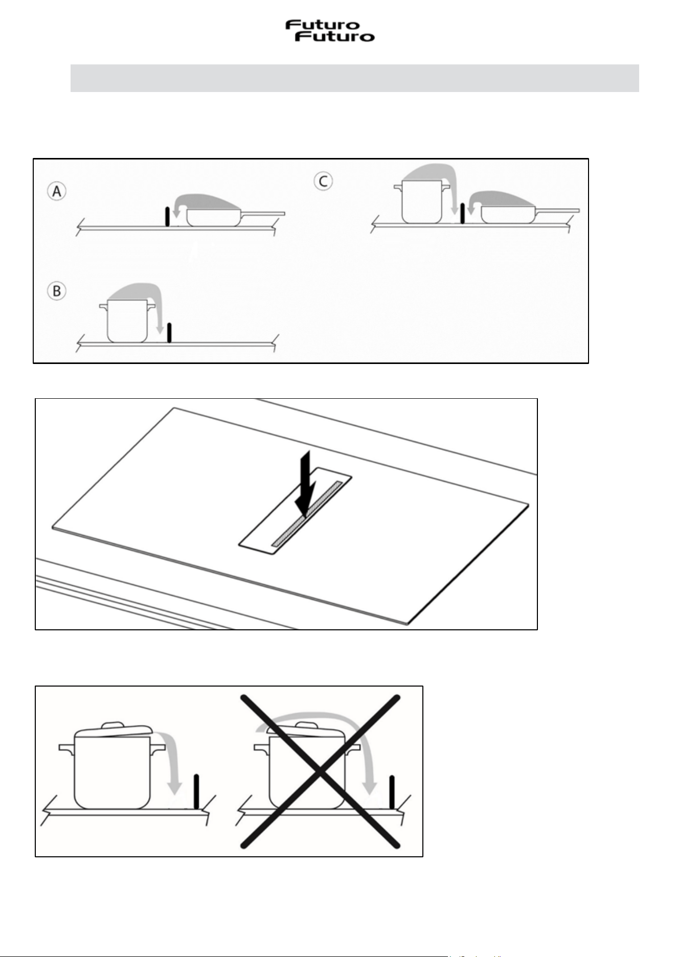
To turn on the aspiration, firstly open the glass flap (Fig. 4.4.a.1)
To open the glass flap, simply press on any point on the outside of the flap itself (Fig. 4.4.a.2).
To facilitate better extraction of the fumes, try to make them exit from the part closest to the
extraction (Fig. 4.4.a.3).
Fig. 4.4.a.1
Fig. 4.4.a.3
Fig. 4.4.a.2
41
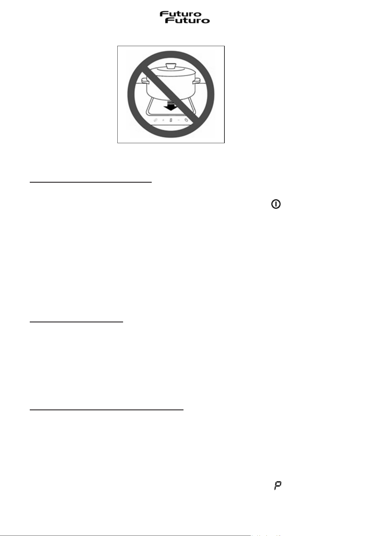
Do not place any objects on the glass flap or on the control panel (Touch Control “TC”) (Fig.4.4.a.4).
IV.4.b EXTRACTION OPERATION
¾ Turning on the extraction system:
-> Open the central glass flap.
-> Touch the ON/OFF key for a few seconds and the symbol will light up.
-> Touch the Selection area (12) to activate the extraction system.
Attention: the extraction area is equipped with a mechanical rotating central flap.
The flap must be opened before activating the extraction system.
The opening flap has an electronic sensor that deactivates the suction when it is closed, this is
to preserve the motor, which would be damaged by operating without air flow.
Only after 30 seconds, the time required for the motor to stop, will it be possible to activate
suction again by opening the flap.
¾ Extraction speed (power):
The extractor is equipped with 9 levels of extraction speed (power).
Touch and slide your fingers along the Selection Bar (4) to increase or decrease:
ї to the right to increase the power level;
і to the left to decrease the power level.
The power level set will be displayed in the Selection/Display area (12)
¾ Booster function "P" (Enhanced Extraction)
The extractor is equipped with an additional power level (Booster, in addition to level 9).
The extractor will go to the supplementary speed (Booster) for 8 minutes and then it will
automatically switch to level 9.
To activate the Booster function, scroll with your fingers along the selection bar (4) beyond level 9
up to "P".
Booster level 1 is indicated in the Selection/Display area (12) with symbol flashing
Fig. 4.4.a.4
42
¾ Automatic Operation
By activating this function, the appliance will switch on at the most suitable speed, adapting the
extraction capacity to the maximum cooking level used in the cooking zones.
When the cooking zones are switched off, the appliance adapts its extraction speed, progressively
decreasing it, removing odours and residual vapours.
Activation:
-> Press the specific key (14)
Deactivation:
-> Press the specific key again (14)
If the hob with Automatic operation active is switched off, the extractor will switch off
automatically, gradually.
¾ Adjustable and Delayed self-switching Off
This function ensures the extraction of any odours and residual vapours. After completing the cooking
process and switching off the hob, the fan continues to run.
There is automatic 5-minute operation at level 1 which starts in the following cases:
-> manual switching off of the hob (ON/OFF) with extractor active
-> shutdown of the extractor in automatic mode using an algorithm
When the function is active in the display (12) point a flashes in the bottom right
When the automatic mode is active, the symbol remains; in manual mode, level 1 is displayed.
In general, the fan speed can be changed even during execution of the function and ends immediately
if 0 is selected.
¾ Extraction timer
It is possible to set an extraction timer similar to that of the cooking zone.
Press on the display (5) and act on "+" and "–" to set the desired timer.
The timer is shown on the Display (5). The timer only starts running when the cooking process is
finished and no further cooking level is set.
The extraction timer can be activated in the following ways:
1. Manual mode 1
-> Both the extraction level and the timer are set and all the cooking zones are switched off.
-> The hob remains on and the suction level remains active for the timer time.
-> Once the timer has elapsed, the hob switches off completely.
43
2. Manual mode 2
-> Both the suction level and the timer are set and the hob is switched off via the ON/OFF button
-> Level 1 of the “Adjustable and Delayed self-switching Off” function is set and remains active for
the time set in the timer.
-> At the end of the time set in the timer, the hob switches off completely.
3. Automatic mode
-> The timer can be set as soon as the extraction is running and starts working as soon as all the
cooking zones are switched off.
-> There is no timer warning after the “Adjustable and Delayed self-switching Off” function expires.
¾ Filter cleaning alert
This function is programmed to alert to the fact that maintenance is due:
Grease filters: every 30 hours
Long life ceramic odour filters: every 120 hours (deactivated by default)
If the anti-odour warning is activated, it will be signalled even if the appliance is not installed in
filtering mode: in this case proceed with normal cleaning of the grease filters and reset the warning.
Activation / Deactivation:
-> Access the User Menu (see HOB CONFIGURATION paragraph) and set it according to your
requirements by following the instructions in the items Overview table (Fig.4.3.c.2) to the code "U1".
Filter cleaning indicator reset:
If the grease filter timer expires, the symbol (13) comes on with a fixed light. It must be pressed
for 5 seconds to reset the filter timer, a appears on the display (12) and the warning count starts
again.
If the odour filter timer expires, the symbol (13) will flash. It must be pressed for 5 seconds to
reset the filter timer, a appears on the display (12) and the warning count starts again.
If both filter timers have expired, the symbol (13) lights up steadily. The grease filter timer must
be pressed for 5 seconds; a will appear on the display (12). After that, the symbol (13) comes
on flashing. It must be pressed for 5 seconds to reset the odour filter timer, a appears on the
display (12) and the warning count starts again.
44
V
MAINTENANCE AND CLEANING
Attention! Before any maintenance or cleaning operation, disconnect the
power supply from the appliance (Fig. 2.1 – Fig. 2.2 WARNINGS chapter).
V.1 CLEANING THE EXTRACTOR INDUCTION HOB
Turn off the appliance before cleaning it.
Do not clean the hob if the glass is too hot as there is a risk of burns.
Remove light stains with a cloth dampened with dish detergent diluted in a little water. Then rinse
with cold water and dry the surface thoroughly.
Highly corrosive or abrasive cleaners and cleaning equipment that can cause scratches should be
strictly avoided.
Never use pressure or steam appliances.
Do not use objects that could scratch the ceramic glass.
Make sure the pot is dry and clean. Make sure there are no specks of dust on the glass ceramic hob
or on the pot. Sliding rough pans will scratch the surface.
Spills of sugar, jam, jelly, etc. must be removed immediately. This will prevent damage to the
surface.
Warning! The following products must NOT be used:
Products containing chlorides, especially those containing hydrochloric acid;
Products based on halides;
Products based on hydrogen peroxide;
Bleaches based on hypochlorous acid;
Aggressive products containing acids;
Detergents containing abrasive powder;
Silver cleaning products;
Detergents whose chemical composition is unknown;
Abrasive pads, brushes or discs;
Rough cloths or rough paper;
Tools that have previously cleaned other metals or alloys.

45
Ordinary cleaning
Do not let dirt accumulate on the external and internal surfaces of the appliance.
For the central glass flap, follow the same instructions indicated for cleaning the induction hob.
Attention: the flap cannot be washed in the dishwasher.
Routine cleaning must be carried out before an excessive accumulation of dirt is created which can
cause abrasive phenomena.
Before carrying out the washing operations, it is necessary to remove any dust particles by blowing
or suctioning them, in order to avoid rubbing on the surface.
Where water has been used as a means of cleaning or rinsing, especially in areas with a significant
presence of limescale, it is advisable to dry the surface to prevent the appearance of stains.
To avoid contamination caused by iron particles, make sure that the tools chosen for cleaning have
not been used previously on other metals or alloys.
Materials for cleaning stainless steel products must be exclusively reserved for this purpose.
Particular care must be paid to the grease filter, which has the function of retaining the grease
particles contained in the vapours, and to the tray below, which has the function of collecting the
grease that could drip from the grease filter. Collect the condensation or collect the liquids
accidentally poured into it through the glass flap.
Both of these elements must be washed when the relevant warning appears or at least once a month
in hot water and detergent, even in the dishwasher, at a temperature not exceeding 50°C.
The filter may become discoloured after a few washes. This is normal and does not mean it has lost
its effectiveness.
To perform maintenance on the metal grease filter and on the tray underneath, it is essential to
remove them from the appliance.
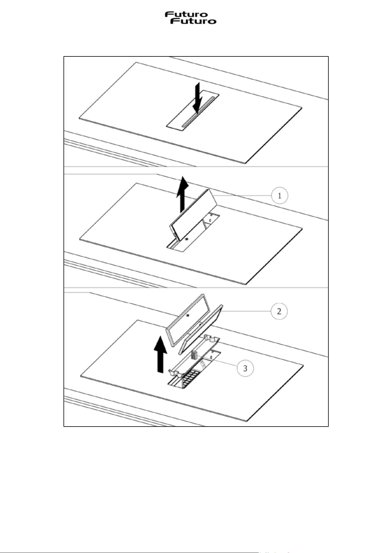
To remove the metal grease filter and the tray, proceed as shown in Fig. 5.1.1:
-> Push down the right side of the central glass flap
-> Remove the central glass flap (1)
-> Grip the metal grease filters by the knob and remove them (2)
-> Remove the condensate collection tray (3)
46
After performing these operations, all the components that have just been removed can be cleaned.
After cleaning, the components must be dried and finally repositioned by carrying out the
operations indicated above (Fig. 5.1.1) in reverse order.
Fig. 5.1.1
47
The long life ceramic anti-odour filters, if present, have the function of retaining unpleasant odours
deriving from cooking and must be regenerated when the relative warning appears.
To regenerate the ceramic odour filters they must be removed from the appliance.
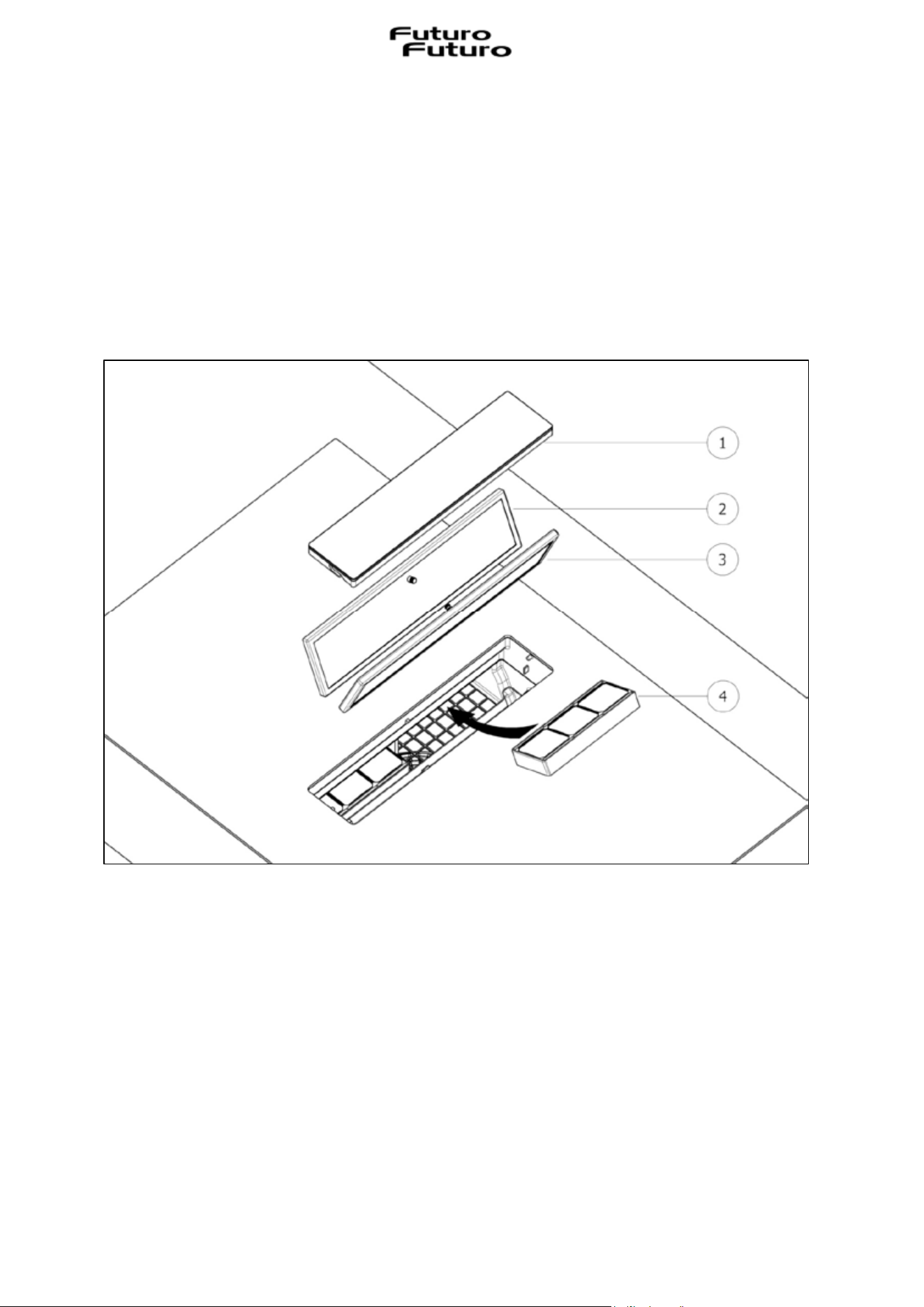
To remove the ceramic anti-odour filters, proceed as illustrated in Fig. 5.1.2:
-> Push down the right side of the central glass flap
-> Remove the central glass flap (1)
-> Grip the metal filters by the knob and remove them both (2,3)
-> Grip the ceramic odour filters and remove them (4)
To regenerate thermally the long life ceramic anti-odour filters, they must be placed in a domestic
oven at 100°C–212°F for 2/3 hours. Correct regeneration ensures constant filtering efficiency for 5
years.
Attention! Do not place the filters on the bottom of the oven, but instead in a tray and place it at
an intermediate height.
To purchase a new filter, request it from the manufacturer.
Fig. 5.1.2
48
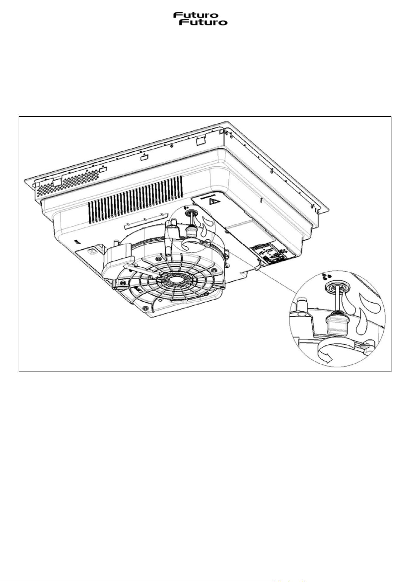
The appliance is equipped with a safety cap to empty any liquids accidentally spilled into the
condensate collection tray, but which have exceeded its capacity. Check daily that there is no
liquid inside the external tank of the hob. To do this, remove the cap under the hob, being sure to
place a container first, under and at the cap itself, to collect any liquids present (see Fig. 5.1.3).
Fig. 5.1.3
49
VI
TROUBLESHOOTING
Warning! During the warranty period, repairs may only be carried out by the authorised After-Sales
Assistance Service.
Ȼ Unauthorised interventions and repairs can cause electric shock or short circuit so avoid
performing them. Leave these tasks to authorised technicians.
Ȼ In the event of small problems, you can try to resolve the problem by following the tips in the
user instructions.
Ȼ The removal of faults or complaints caused by incorrect use or installation of the appliance will
not be covered under warranty. The repair costs will be borne by the user.
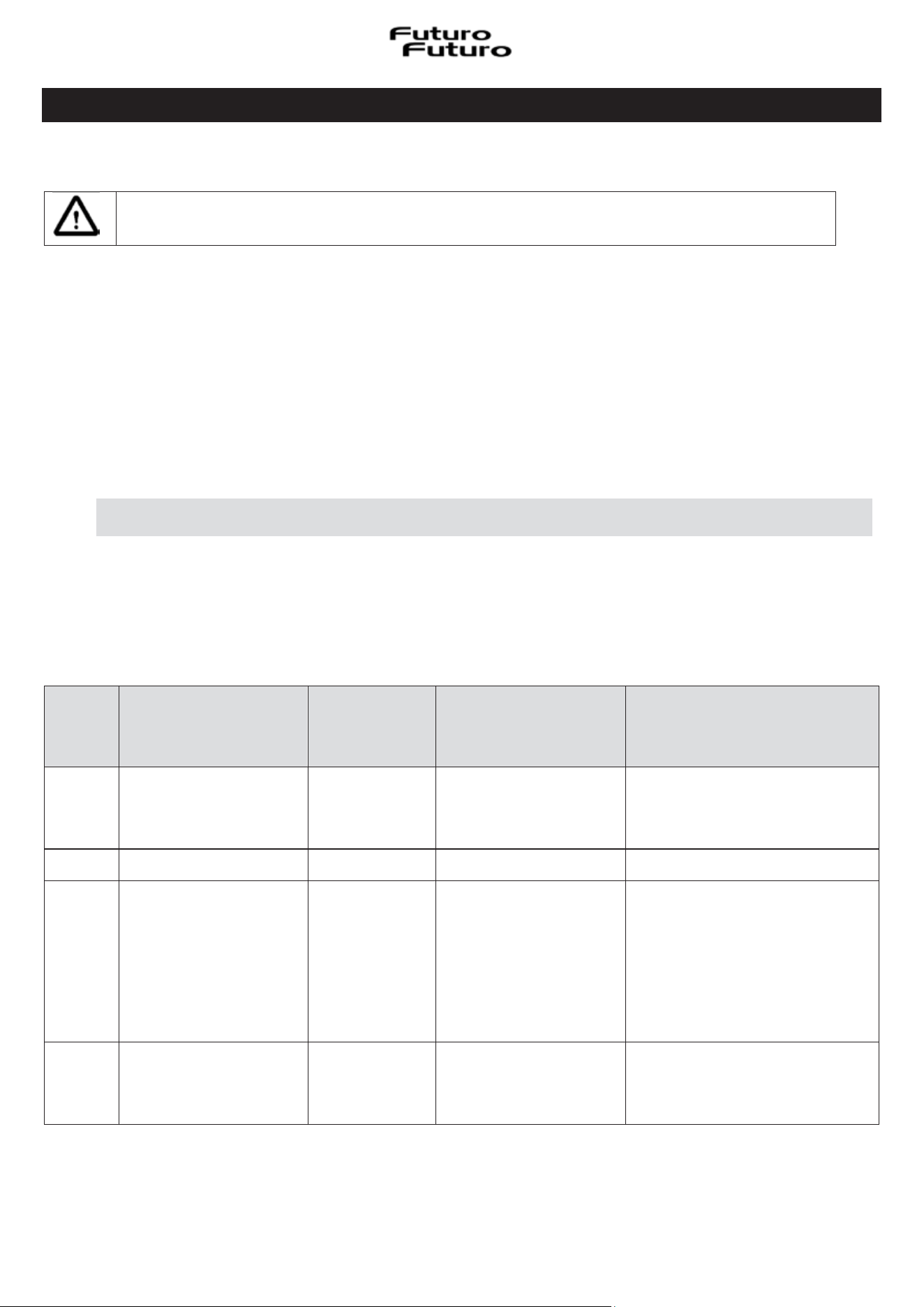
VI.1 ERRORS / TROUBLESHOOTING
The hob is programmed to provide dedicated error codes for quick and efficient troubleshooting.
The cooking zone displays show error codes.
An error code always begins with the letters “E” or “ER” depending on the electronic component
that generated the error.
Error
Code
Meaning
Error
Behaviour
of the hob
Cause
possible
Solution
Problem
ER03
Continuous activation
of a key has been
detected
Shutdown
after 10
seconds
Water or pots placed
on the TC*
Remove water or pots from the
TC*
ER20 Internal error at TC* Shutdown - Replace TC*
ER21 Overheating Shutdown
The temperature
sensor on TC* has
detected a
temperature
> 85°C–185°F
Let the hob cool down (the
error disappears if the
temperature is < 75°C–167°F).
Check the thermal insulation of
the TC*
ER22 Internal error at TC*
Switch off
after 3.5 - 7.5
seconds
- Replace TC*
Attention! Before any maintenance or cleaning operation, disconnect the
power supply from the appliance (Fig.2.1 – Fig. 2.2 WARNINGS chapter).
50
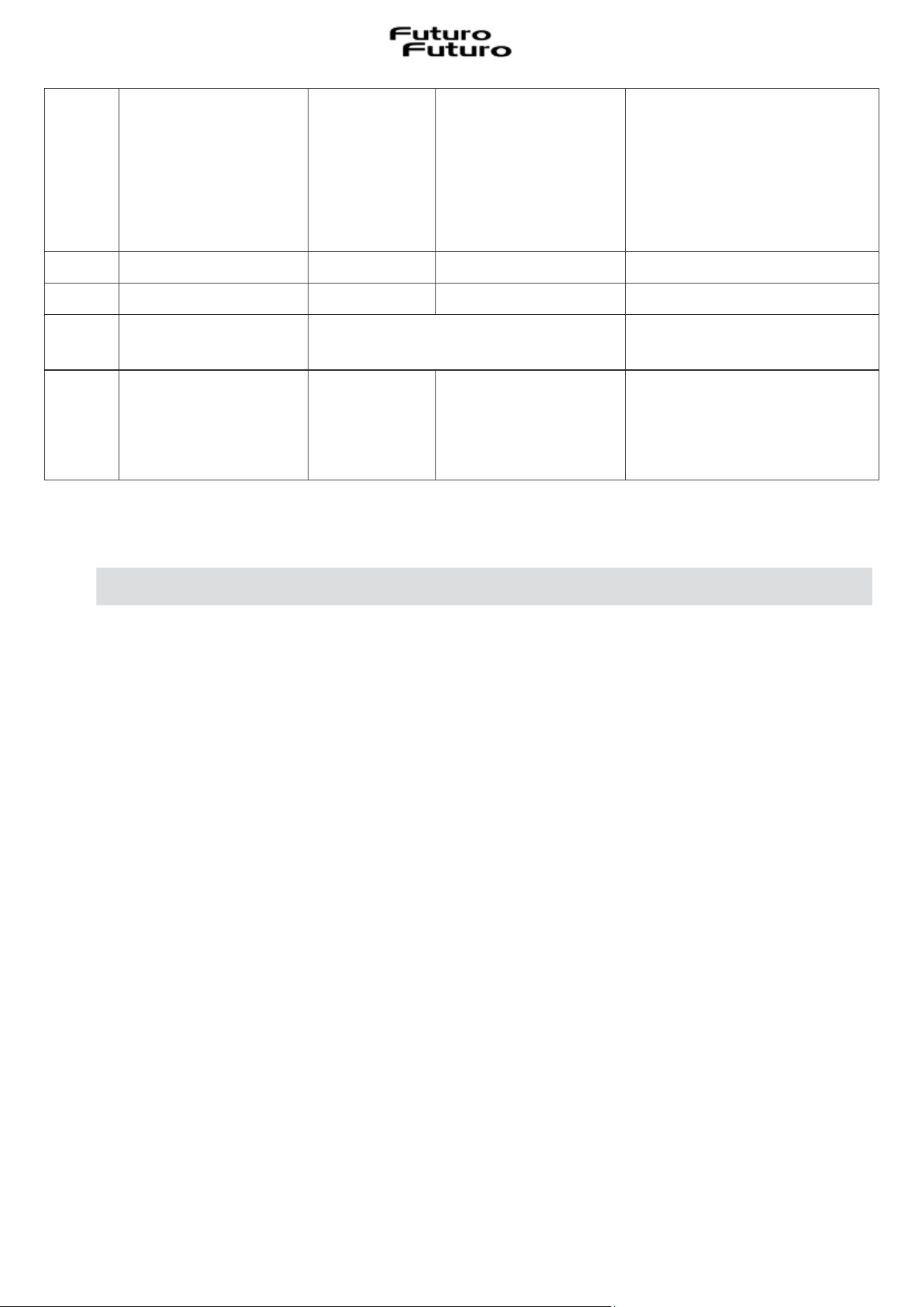
ER31
The internal
configurations of the
TC* and induction are
incongruous
ER31 is
displayed
continuously
The internal
configuration data of
the induction
generator is different
from the configuration
inside the TC*
Download the configuration.
If the error is still present,
replace the TC*. If the error is
still present, replace the
induction generator.
ER35 Internal error at TC* Shutdown -
Replace TC*
ER36 Internal error at TC* Shutdown -
Replace TC*
ER42
Secondary power
supply not suitable
12V or 5V too high / too low
ER47
No communication to
at least one coupled
LIN
ER47 is
displayed
continuously
Damaged LIN cable. No
supply voltage for
coupled LIN.
Faulty coupled LIN.
Check and replace the LIN
wiring.
Check the supply voltage.
Replace coupled LIN.
(*) TC = Touch Control (Control Panel)
VI.2 ASSISTANCE SERVICE
Before contacting the Assistance Service it is important to:
-> Check if the problem can be resolved by consulting the error table in the
"Errors/Troubleshooting" paragraph.
-> Switch the appliance off and on again (ON/OFF) to make sure that the problem has been
resolved.
Finally, if after carrying out the above checks the error signals persist, contact the Assistance
Service.
51
VII
DECOMMISSIONING
VII.1 DECOMMISSIONING
Decommissioning means the definitive shutdown and dismantling of the appliance.
After decommissioning, the appliance can be incorporated into another unit, resold privately or
disposed of.
Attention! To put it out of service, it is necessary to switch off the appliance and
disconnect the power supply from the appliance (Fig. 2.1-2.2 WARNINGS chapter).
Attention! Only have the electrical lines disconnected and closed by specialist
personnel.
VII.2 DISASSEMBLY
Disassembly requires that the device is accessible for disassembly and has been disconnected from
the voltage supply.
To do this, proceed as follows:
Loosen the screws and fixing brackets
Remove any silicone sealants
Pull the hob out from above
VII.3 PROTECTING THE ENVIRONMENT
The packaging materials are environmentally-friendly and recyclable.
The electronic devices consist of materials that are recyclable but sometimes harmful for the
environment, but necessary for the correct functioning and safety of the appliance.
VII.4 DISPOSAL
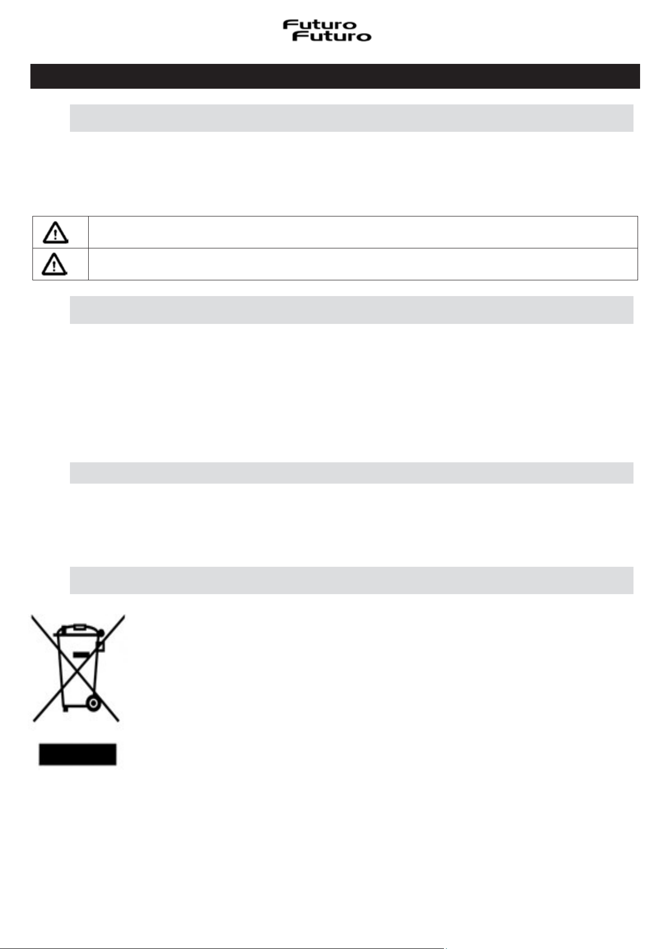
This appliance is marked in accordance with the European Directive 2012/19/EC,
Waste Electrical and Electronic Equipment (WEEE).
The symbol on the product or on the packaging indicates that the product must
not be treated as normal household waste, but must be taken to the appropriate
collection point for the recycling of electrical and electronic equipment.
By ensuring that this product is disposed of correctly, you will help prevent
potential negative consequences for the environment and for human health. For
detailed information about recycling this product, contact your council, your local
waste collection service or the store where you purchased the product.

395.859