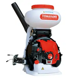
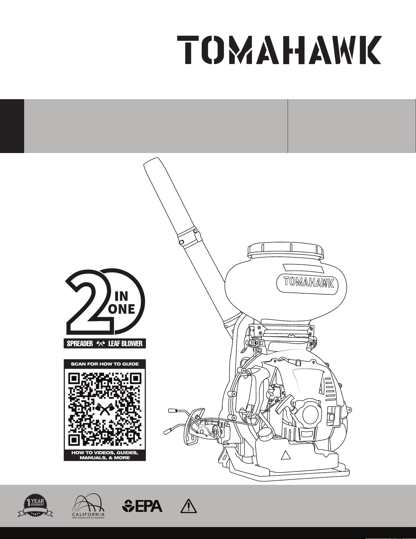
Operation Manual
To reduce the risk of injury, the user must read and understand the Operator’s
Manual before using this product. Save these instructions for future reference.
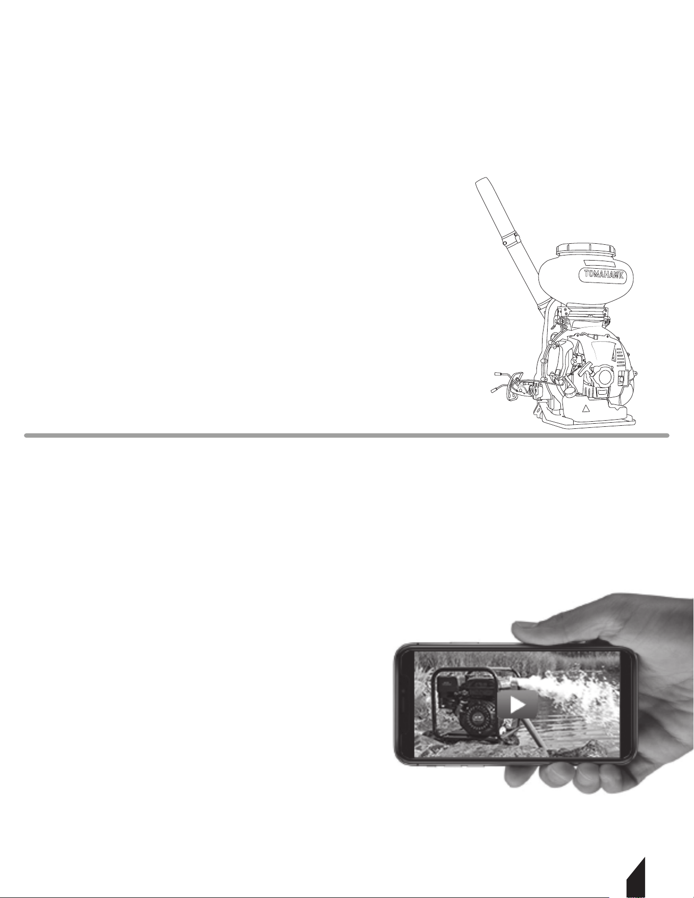
4 GALLON
FERTILIZER SPREADER
MODEL NUMBER: TGS30
W
A
R
R
A
N
T
Y

2
1. SAFETY INFORMATION
1.1 Operating Safety
1.2 Service Safety
1.3 Safety While Using Combustion Engines
1.4 Service Safety
1.5 Chemical Handling
2. GENERAL INFORMATION
2.1 Design and Features
2.2 TOMAHAWK® Engine
2.3 Specifications
3. ASSEMBLY
4. OPERATION
4.1 Start Up Guide
4.2 Stopping the Engine
4.3 Filling the Tank
4.4 Spreading
5. TRANSPORTATION & STORAGE
6. CARBURETOR ADJUSTMENT GUIDE
7. REPLACEMENT PARTS
8. WARRANTY
9. MAINTENANCE
10. TROUBLESHOOTING
12. PARTS MANUAL
14. CALIFORNIA EMISSION CONTROL WARRANTY
Table of Contents
4
5
5
6
6
7
7
7
7
7
8
11
11
12
13
13
13
14
15
15
16
17
19
28
3
Register Your Equipment
Thank you for purchasing TOMAHAWK® equipment! Your product is covered by the
TOMAHAWK® Warranty Policy, but in order to activate your warranty, we need you to register
your product. In addition to activating your equipment warranty, product registration will
grant you access to important product updates, streamlined customer service, and more.
INCLUDED WITH YOUR REGISTRATION
☑ Equipment Warranty Activation
☑ Product Updates
☑ Streamlined Customer Service
☑ Exclusive Discounts and Sales
STEPS TO REGISTER YOUR EQUIPMENT
1. Visit www.tomahawk-power.com
2. Choose “Product Registration” at the bottom of the page
3. Enter your equipment’s serial number to get started
4. Provide all required information
5. Submit Registration
Equipment Resources
TOMAHAWK® Customer Service doesn’t stop at checkout. We understand to keep a job-site
running smoothly - the proper equipment, spare parts, instruction manuals, and more are
needed at the drop of a hat. Visit www.tomahawk-power.com to gain access to the incredible
resources below.
How To Video Library
More of a visual person? Visit our Video Library for equipment
assembly instructions, troubleshooting tips, and more!
Found on each product listing or the Service Videos Page
Manual and Assembly Guide Library
Visit our Manual Library if you are looking for a lost
operations manual or a particular spare part?
Found on each product listing or the Tomahawk Manuals Page
Service Requests
In need of a quick fix or a service center referral? Submit a
Service Request and a Tomahawk Technician will respond
shortly to get you the help you need.
Choose “Service Request” at the bottom of www.tomahawk-power.com
4
This manual provides information and procedures to safely operate and maintain this
equipment. For your own safety and protection from injury, carefully read, understand and
observe the safety instructions described in this manual.
Keep this manual or a copy of it with the equipment. If you lose this manual or need an
additional copy, please contact Tomahawk Power LLC or visit www.tomahawk-power.com
This equipment is built with user safety in mind; however, it can present hazards if
improperly operated and serviced. Follow operating instructions carefully. If you have
questions about operating or servicing this equipment, contact Tomahawk Power.
The information contained in this manual is based on equipment’s production at the time of
publication. Tomahawk Power reserves the right to change any portion of this information
without notice.
No part of this publication may be reproduced in any form or by any means, electronic or
mechanical, including photocopying, without express written permission from
Tomahawk Power.
Any type of reproduction or distribution not authorized by Tomahawk Power represents an
infringement of valid copyrights and will be prosecuted. We expressly reserve the right to
make technical modifications, even without due notice, which aim at improving our
machines or their safety standards.
1. SAFETY INFORMATION
This manual contains DANGER, WARNING, CAUTION, and NOTE call-outs which must be
followed to reduce the possibility of personal injury, damage to the equipment, or improp-
er service.
This is the safety alert symbol. It is used to alert you to potential personal injury
hazards. Obey all safety messages that follow this symbol to avoid possible injury
or death.
DANGER indicates an imminently hazardous situation which, if not avoided, will
result in death or serious injury.
WARNING indicates a potentially hazardous situation which, if not avoided, could
result in death or serious injury.
CAUTION indicates a potentially hazardous situation which, if not avoided, may
result in minor or moderate injury.
DANGER
WARNING
CAUTION

5
CAUTION: Used without the safety alert symbol, CAUTION indicates a potentially hazardous
situation which, if not avoided, may result in property damage.
1.1 Laws Pertaining to Spark Arresters
Notice: State Health Safety Codes and Public Resources Codes specify that in certain
locations spark arresters be used on internal combustion engines that use hydrocarbon
fuels. A spark arrester is a device designed to prevent accidental discharge of sparks or
flames from the engine exhaust. Spark arresters are qualified and rated by the United States
Forest Service for this purpose.
In order to comply with local laws regarding spark arresters, consult the engine distributor or
the local Health and Safety Administrator.
1.2 Operating Safety
Familiarity and proper training are required for the safe operation of equipment!
Equipment operated improperly or by untrained personnel can be dangerous! Read
the operating instructions contained in both this manual and the engine manual and
familiarize yourself with the location and proper use of all controls. Inexperienced operators
should receive instruction from someone familiar with the equipment before being allowed
to operate the machine.
1.2.1 NEVER allow anyone to operate this equipment without proper training. People
operating this equipment must be familiar with the risks and hazards associated with it.
1.2.2 NEVER touch the engine or muffler while the engine is on or immediately aer it has
been turned off. These areas get hot and may cause burns.
1.2.3 NEVER use accessories or attachments that are not recommended by Tomahawk
Power. Damage to equipment and injury to the user may result.
1.2.4 NEVER leave machine running unattended.
1.2.5 ALWAYS be sure operator is familiar with proper safety precautions and operation
techniques before using machine.
1.2.6 ALWAYS wear ANSI Z87.1-approved safety goggles or safety glasses with side shields,
or when needed, a face shield. Use a dust mask in dusty work conditions. Also use non-skid
safety shoes, hardhat, gloves, dust collection systems, and hearing protection when
appropriate. This applies to all persons in the work area.
1.2.7 ALWAYS close fuel valve on engines equipped with one when machine is not being
operated.
1.2.8 ALWAYS store equipment properly when it is not being used. Equipment should be
stored in a clean, dry location out of the reach of children.
1.2.9 ALWAYS operate machine with all safety devices and guards in place and in working
order. DO NOT modify or remove safety devices. DO NOT operate machine if any safety devic-
es or guards are missing or inoperative.
1.2.10 ALWAYS read, understand, and follow procedures in Operator's Manual before
attempting to operate equipment.
WARNING

6
1.3 Safety while using Combustion Engines
Internal combustion engines present special hazards during operation and fueling!
Read and follow warning instructions in engine owner's manual and safety guidelines
below. Failure to follow warnings and DANGER safety guidelines could result in severe injury
or death.
1.3.1 DO NOT run machine indoors or in an enclosed area such as a deep trenches unless
there is adequate ventilation, through such items as exhaust fans or hoses are provided. Gas-
oline exhaust from the engine contains poisonous carbon monoxide gas; exposure to carbon
monoxide can cause loss of consciousness and may lead to death.
1.3.2 DO NOT smoke while operating machine.
1.3.3 DO NOT smoke when refueling engine.
1.3.4 DO NOT refuel hot or running engine.
1.3.5 DO NOT refuel engine near open flame.
1.3.6 DO NOT spill fuel when refueling engine.
1.3.7 DO NOT run engine near open flames.
1.3.8 ALWAYS refill fuel tank in well-ventilated area.
1.3.9 ALWAYS replace fuel tank cap aer refueling.
1.3.10 ALWAYS check fuel lines and fuel tank for leaks and cracks before starting engine.
1.3.11 DO NOT run machine if fuel leaks are present or fuel lines are loose.
1.4 Service Safety
Poorly maintained equipment can become a safety hazard! In order for the
equipment to operate safely and properly over a long period of time, periodic
maintenance and occasional repairs are necessary.
1.4.1 DO NOT attempt to clean or service machine while it is running. Rotating parts can
cause severe injury.
1.4.2 DO NOT crank a flooded engine with the spark plug removed on gasoline-powered
engines. Fuel trapped in the cylinder will squirt out the spark plug opening.
1.4.3 DO NOT test for spark on gasoline-powered engines, if engine is flooded or the smell of
gasoline is present. A stray spark could ignite fumes.
1.4.4 DO NOT use gasoline or other types of fuels or flammable solvents to clean parts,
especially in enclosed areas. Fumes from fuels and solvents can become explosive.
1.4.5 ALWAYS keep area around muffler free of debris such as leaves, paper, cartons, etc. A
hot muffler could ignite them, starting a fire.
1.4.6 ALWAYS replace worn or damaged components with spare parts designed and
recommended by Tomahawk Power.
1.4.7 ALWAYS disconnect spark plug on machines equipped with gasoline engines, before
servicing, to avoid accidental start-up.
1.4.8 ALWAYS keep machine clean and labels legible. Replace all missing and hard-to-read
labels. Labels provide important operating instructions and warn of dangers and hazards.
1.4.9 ALWAYS check for damaged parts before each use. Carefully check that the trowel will
operate properly and perform its intended function. Replace damaged or worn parts
immediately. Never operate the trowel with a damaged part.
DANGER
WARNING
7
1.5 Chemical Handling
1.5.1 ALWAYS wear eye protection when handling chemicals.
1.5.2 ALWAYS wear the proper protective equipment/clothing when handling chemicals.
Proper protective equipment includes safety goggles or glasses, mask/respirator, and a
long-sleeved shirt and long pants.
1.5.3 ALWAYS use mask to protect mouth and face from dust and/or pesticide when
handling chemicals.
1.5.4 ALWAYS aer spraying, wash hands and clothing immediately.
2. GENERAL INFORMATION
2.1 Design and Features
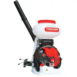
Tomahawk Motorized Fertilizer Spreaders are great for Year Round Use! Not just perfect for
Spring and Summer Landscaping and Pest Control, but also an incredible Leaf Blower and
Ice Melt solution during Autumn and Winter! Unlike ordinary spreaders, Tomahawk
Motorized Spreaders are powered by a 63.3cc/3HP, 2 stroke engine that generates an
extreme blowing force with 30 of Horizontal Reach!
2.2 TOMAHAWK® Engine
The ultra-lightweight, 2-Stroke, 3HP engine efficiently delivers the power and performance
that you’d expect from a larger engine – but in a very compact package
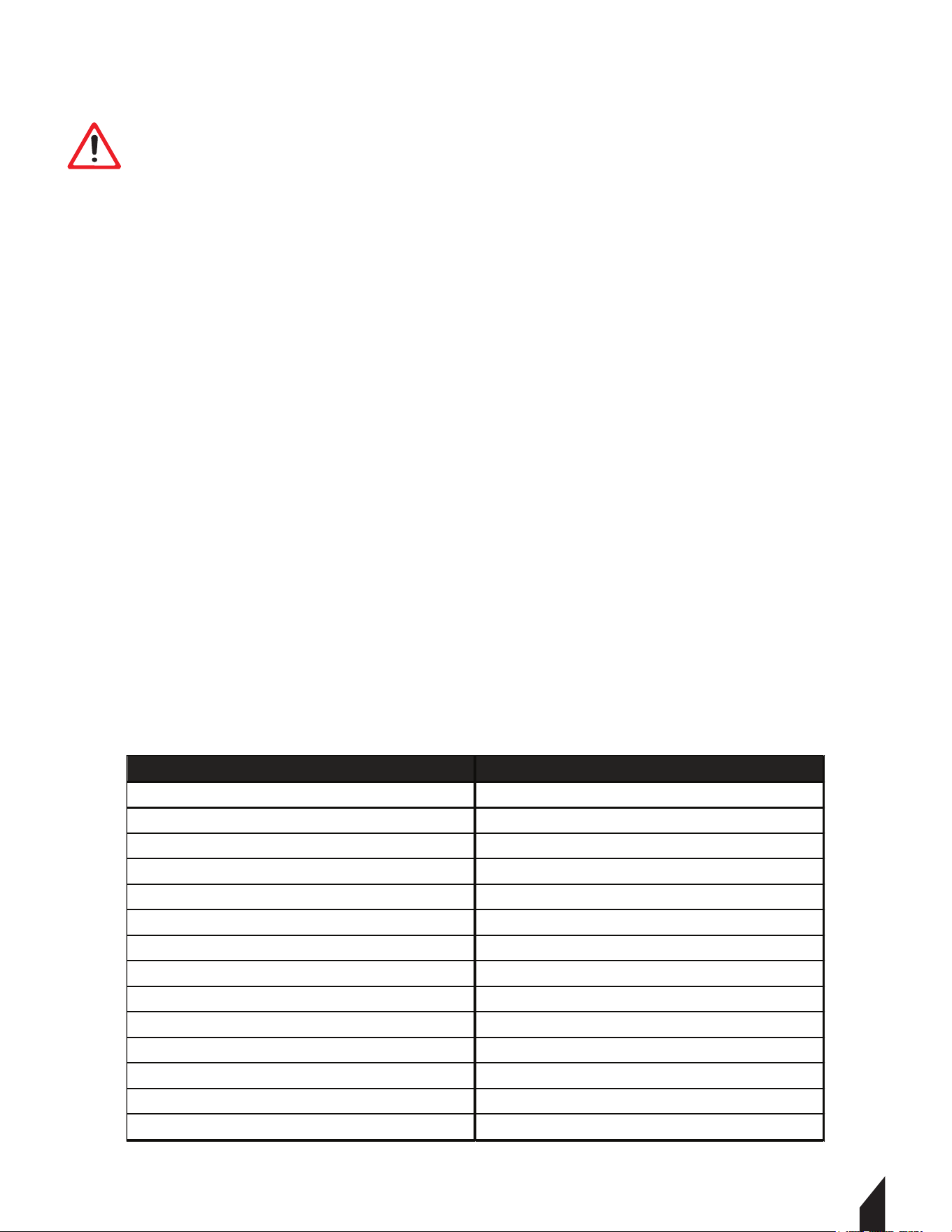
2.3 Specifications
DANGER
FOR USE WITH WATER-BASED OR WATERBORNE COMPOUNDS ONLY. DO NOT USE
EQUIPMENT WITH SOLVENT-BASED OR EXPLOSIVE LIQUIDS. FAILURE TO COMPLY MAY CAUSE
SERIOUS BODILY HARM OR DEATH. READ ALL CHEMICAL MANUALS BEFORE OPERATION.
Model TGS30
Engine 3HP 2 Stroke Engine
Displacement 63.3 cc
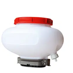
Chemical Tank 4 gal (14l)
Fuel Capacity 1.1 qt
Horizontal Reach 30ft (9m)
Vertical Reach 15+ft (4.5+m)
Air Speed 220 MPH (354KPH)
Air Volume 490 CFM
MPA 1.0 - 2.5
Start Type Recoil Cord
Fan Rotation Speed 7300 RPM
Weight 35 lbs (15.8kg)
Dimensions 21x17x26 in (53.3x43.1x66 cm )
Recommended Fuel
50:1 Pre-Mix (Not Included)
8
3. ASSEMBLY
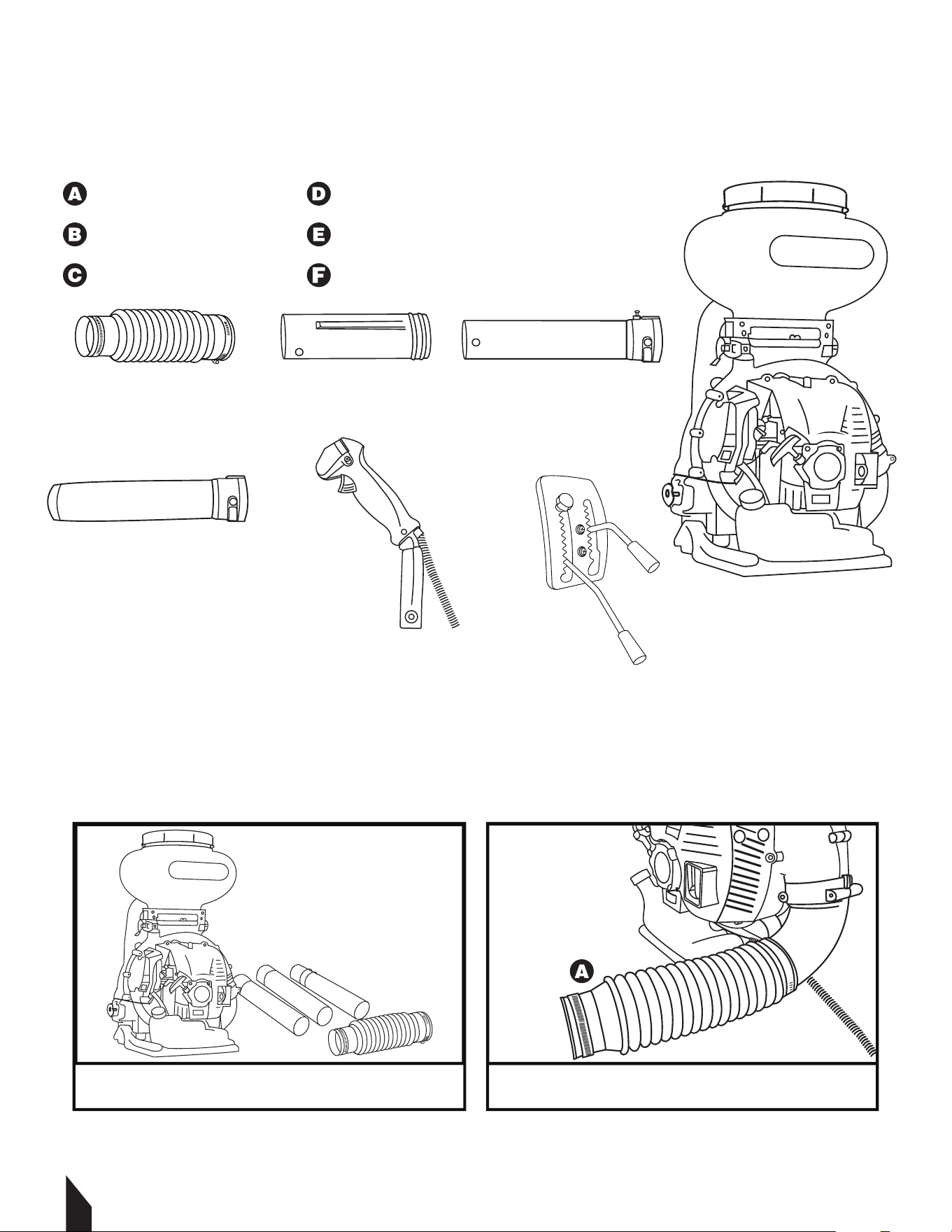
3.1 Spreader Parts
Remove all parts from the packaging. You will not need all parts for this set up.
Additional Parts
Backpack Straps
Tool Kit
Tube Clamps
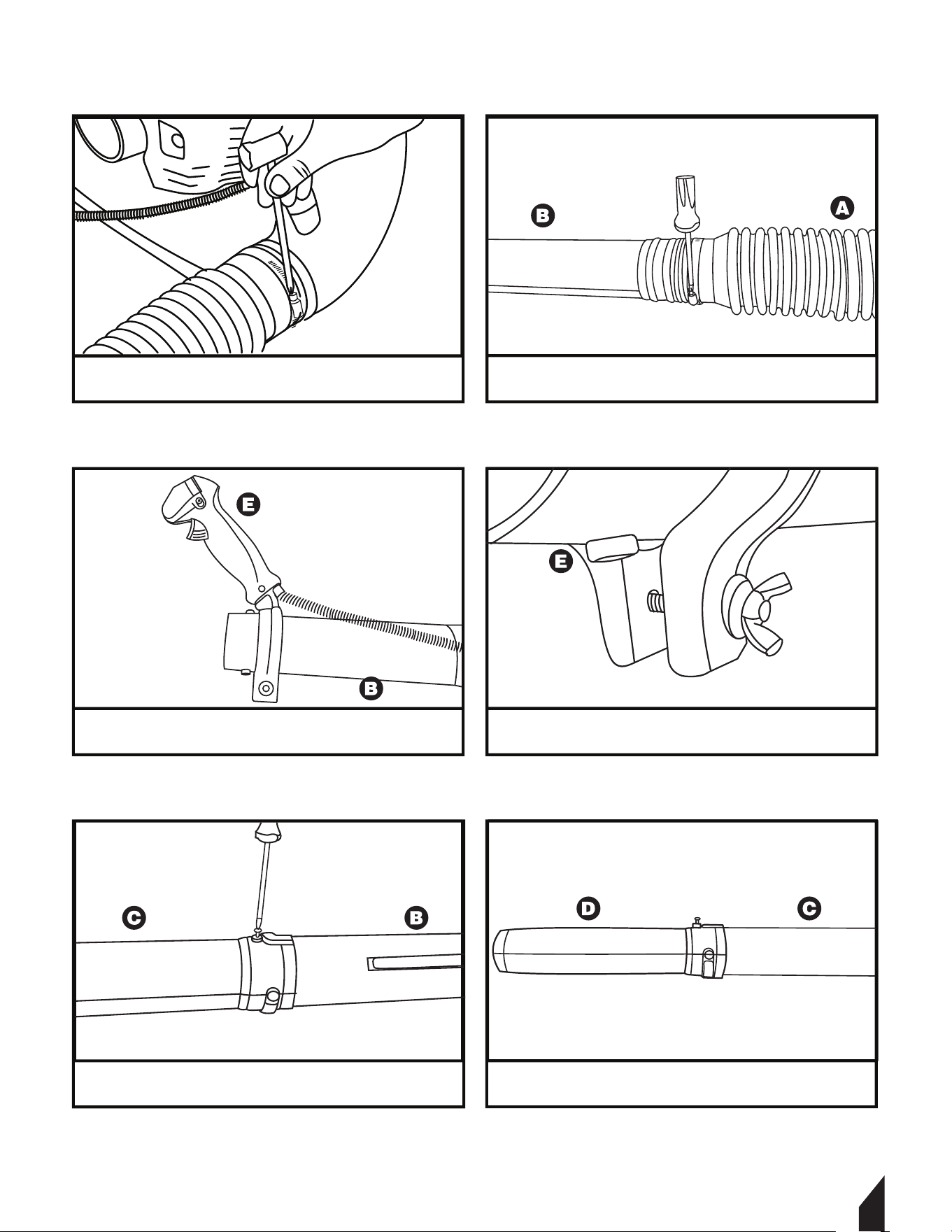
3.2 Assembly Guide
Ribbed Tube
Throttle Tube
Extension Tube
Blower Tube
Throttle Control Handle
Volume Control Lever
A B C
D E F
2
Attach the ribbed tube (A) to the spreader’s
blower elbow.
1
Remove all parts from the spreader box,
including the tool kit bag.
3.2 Assembly Guide Continued
9
4
Attach the throttle tube (B) and secure it to
the ribbed tube (A) with a hose clamp.
3
Secure the ribbed tube (A) with a hose
clamp to the spreader’s blower elbow.
5
6
Fasten the base of the throttle control
handle (E) with the wing nut.
Slide the throttle control handle (E) over the
throttle tube (B)
8
Attach the blower tube (D) and secure it to
the extension tube (C) with a hose clamp.
7
Attach the extension tube (C) and secure it
to the throttle tube (B) with a hose clamp.
3.2 Assembly Guide Continued
10
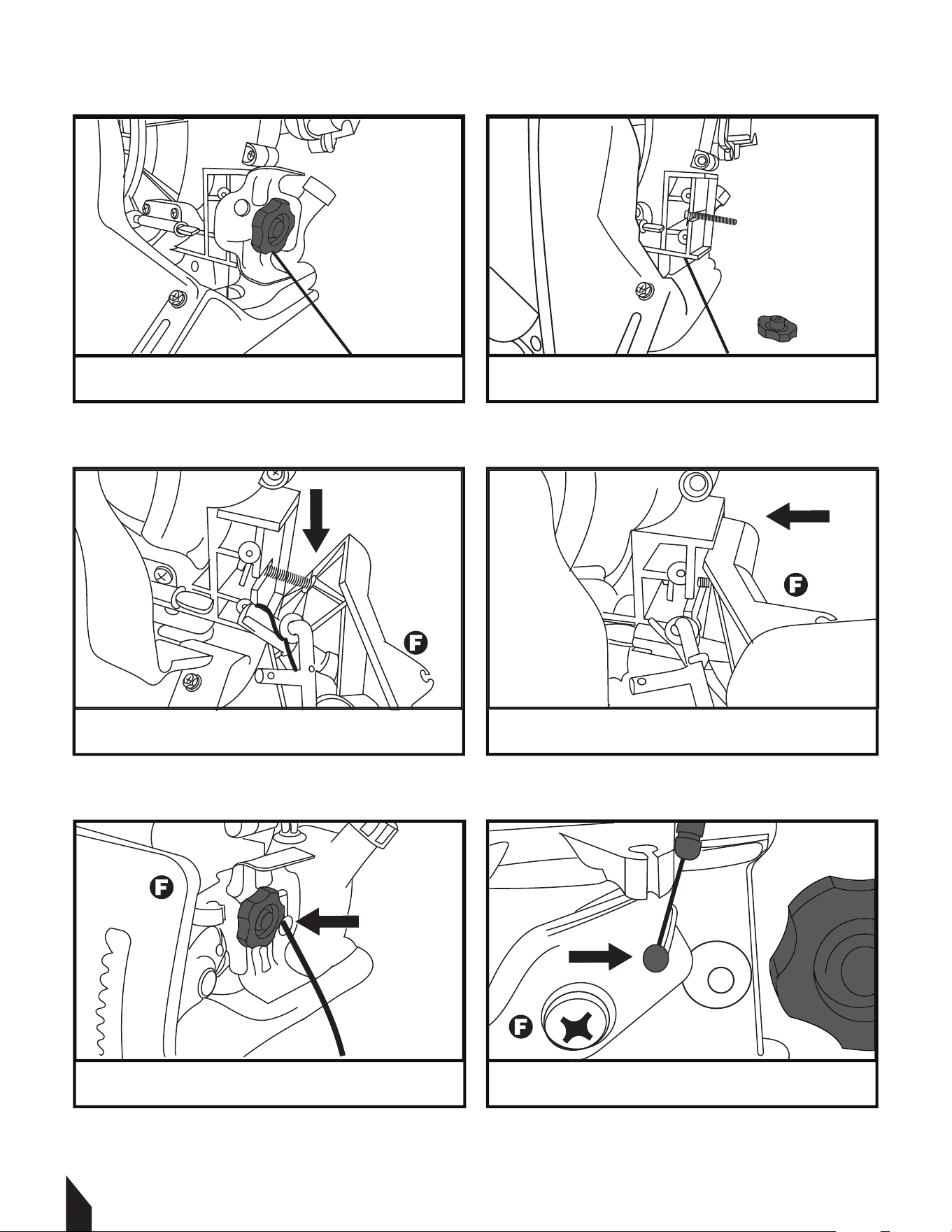
10
Remove the knob to access the bolt.
9
Locate the volume lever assembly behind
the fuel tank.
12
Align the volume control lever’s slot (F)
into place and line up the housing.
11
Push the bolt through the back of the
volume control lever (F).
14
Press the throttle cable’s end into the slot
of the volume lever (F).
13
Thread the throttle cable through the hole in the
volume lever assembly and fasten the knob.
3.2 Assembly Guide Continued
4. OPERATION
4.1 Start Up Guide
11
16
Move the STOP LEVER up to lock the
throttle cable into the upper channel.
15
Move the STOP LEVER down to lock the
throttle cable into the lower channel.
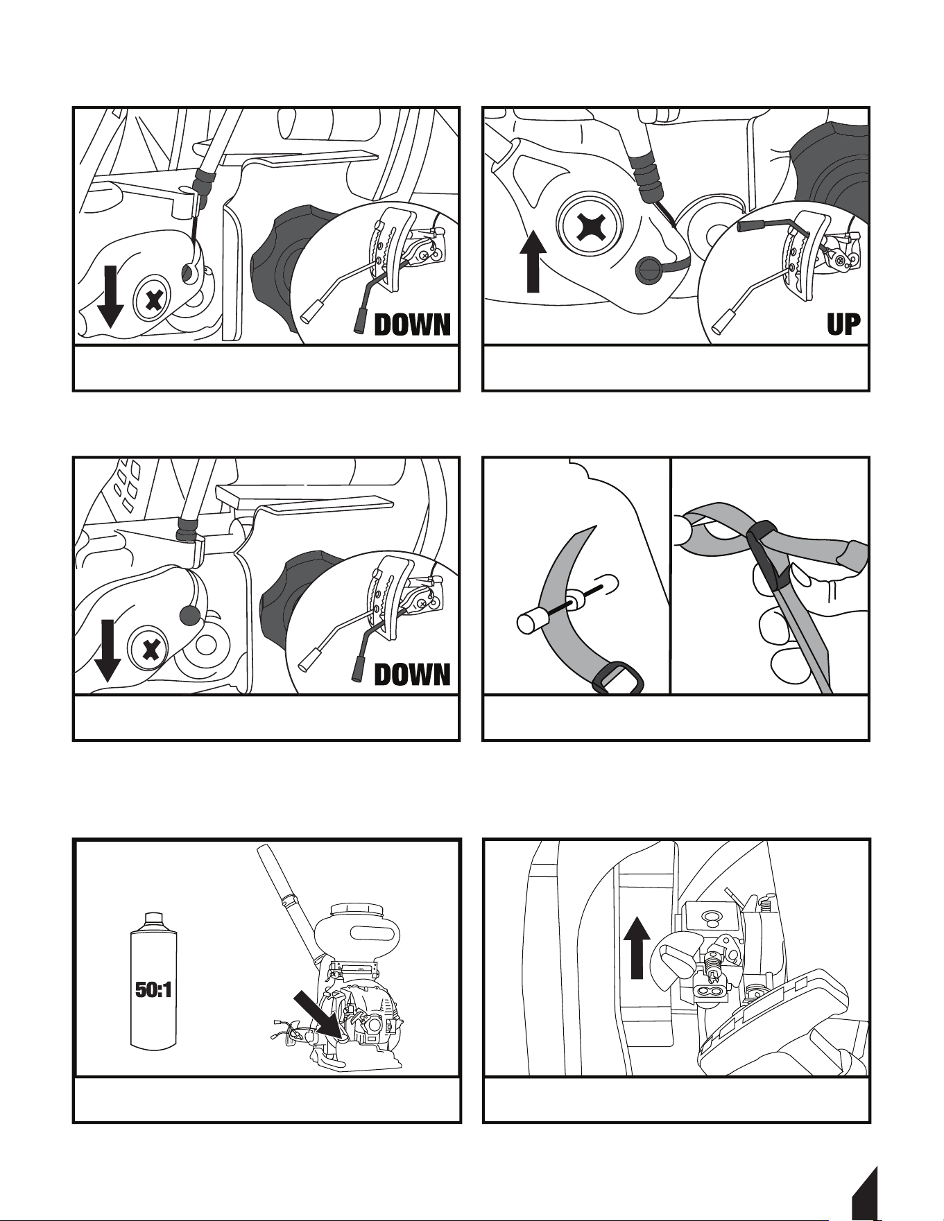
18
To attach the straps, feed the end through
the metal bar and down through the buckle.
17
Move the STOP LEVER down to lock the
throttle cable into the last channel.
2
Turn the choke to the UP position.
1
Fill the spreader’s fuel tank with
50:1 pre-mixed fuel.
4.2 Stopping the Engine
4.2.1 Lower the STOP LEVER down.
4.1 Start Up Guide Continued
12
*If the DUST LEVER is raised up during start up, any material in the tank will
be released and may be wasted.
4
Move the STOP LEVER up.
Keep the DUST LEVER down.*
3
Press the fuel injection bulb 3-5 times or until
fuel is seen flowing though the fuel lines.
6
Turn the choke to the DOWN position.
5
Pull the engine’s recoil starter cord until the
engine starts.
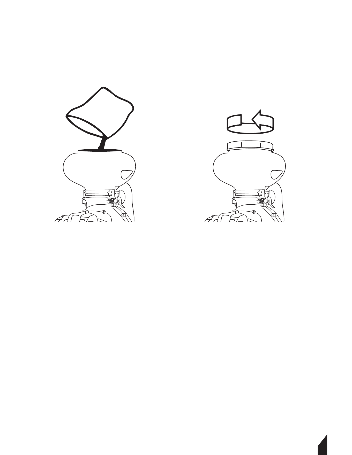
4.3 Filling the Tank
4.3.1 Keep the Dust Lever Down
4.3.2 Remove the lid and pour the chemical in the tank, being careful not to spill it on the
outside. Only fill the tank with the amount to be spread.
4.3.3 Fasten the lid on the tank. If the lid is loose, it may affect the operation.
4.4 Spreading
4.4.1 Using the throttle handle will control the speed of the engine - to adjust the distance
and spread of the granules spread.
4.4.2 Using the dust lever adjusts the amount granular chemicals that leave the tank. In
the down position no granular chemicals will spread. In the up position the maximum
amount of granular will enter through the fertilizer spreader
NOTE: At full throttle the spreader with the lever all the way up the this product will
spread up to 38lbs of fertilizer/ small granular per minute.
5. TRANSPORTATION & STORAGE
5.1 Empty the tank of all chemicals and flush the system and hoses with 2 tanks of clean
water.
5.2 Secure the equipment during transportation in order to avoid transport damage.
5.2 For longer storage periods, drain the fuel tank and run the engine until it stalls to
eliminate any remaining fuel in the carburetor. Apply a light coat of oil to the cylinder and
spark plug hole.
5.3 ALWAYS Store the equipment upright, in a lockable, dry area - out of reach of children
and unauthorized persons.
13
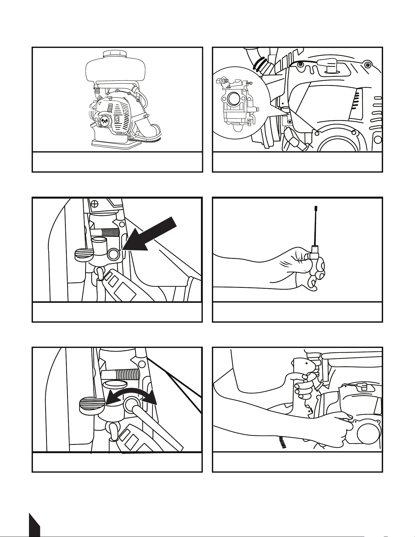
6. CARBURETOR ADJUSTMENT GUIDE CONTINUED
14
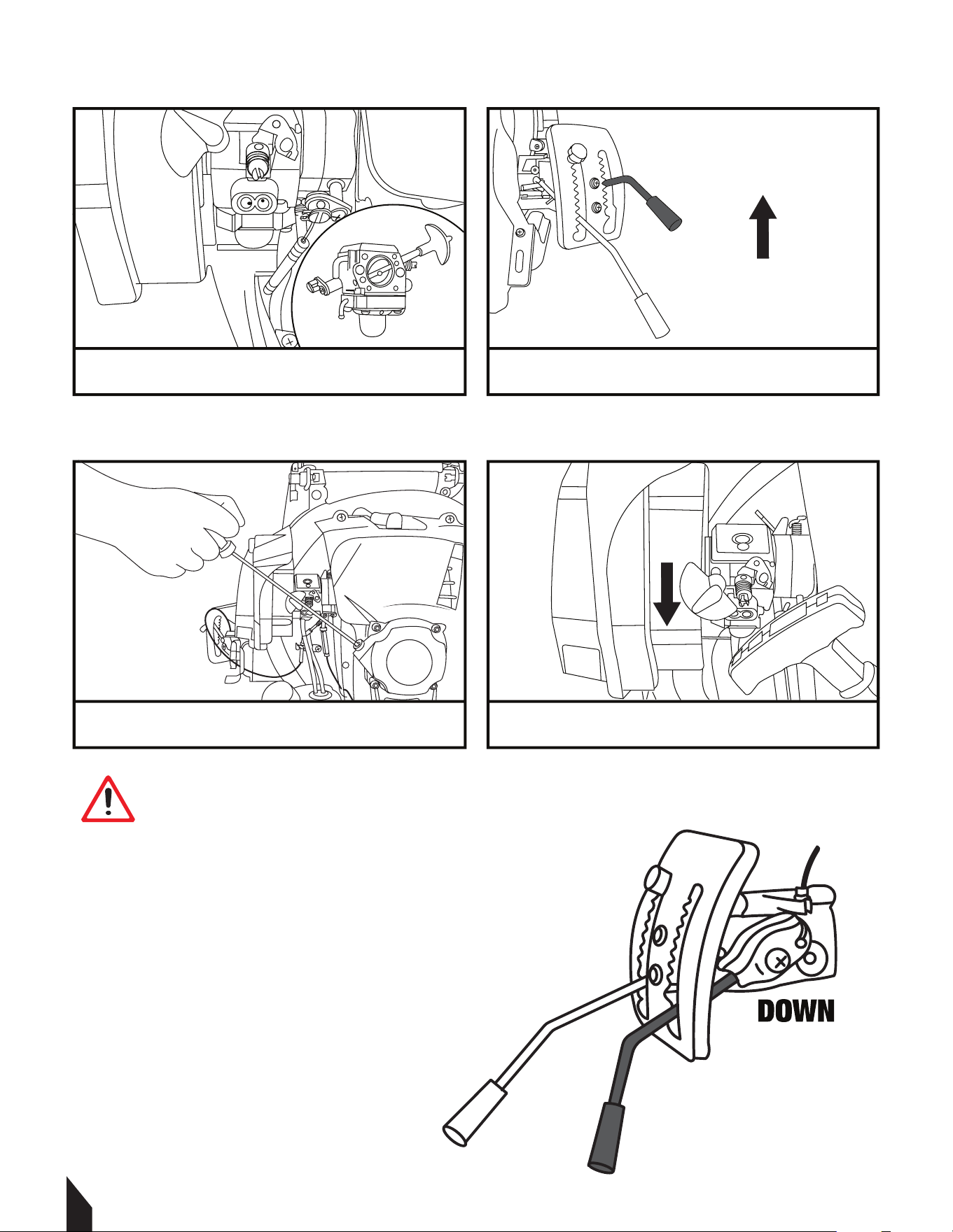
2
Identify the engine’s carburetor in between
the engine cover and air filter.
1
If your spreader engine is bogging down or only
runs with the choke open, follow these steps.
4
Use the carburetor adjustment tool* to tune
the carburetor while the engine is running.
3
Tune up your carburetor by adjusting the
keyhole. (pictured above)
6
Use the spreader’s throttle handle to listen for a
high pitch, steady hum & find the right speed.
5
Turn the tool to the left or right until the
engine is running correctly.
*Carburetor adjustment tool not included. Visit www.tomahawk-power.com for carburetor
adjustment tools and a wide assortment of attachments and spraying nozzles.

15
15
7. REPLACEMENT PARTS
7.1 For replacement parts and technical questions visit www.tomahawk-power.com or scan
the QR code on the front of this manual.
7.2 Not all equipment components are available for replacement. The illustrations within
this manual are a convenient reference to the location and position of parts in the assembly
sequence.
7.3 When ordering parts, the following will be required: equipment model number, serial
number/lot, date code, and description. The distributor reserves the right to make design
changes and/or improvements to equipment, parts, accessories, and manuals without
notice.
8. WARRANTY
Your new TOMAHAWK® equipment is warranted to the original purchaser for a period of
one-year (12 months) from the original date of purchase. The TOMAHAWK® warranty is
against defects in design, materials and workmanship.
The following are not covered under the warranty:
8.1 Damage caused by abuse, misuse, dropping or other similar damage caused by or as a
result of failure to follow assembly, operation or user maintenance instructions.
8.2 Alterations, additions or repairs carried out by persons other than TOMAHAWK® or their
recognised agents.
8.3 Transportation or shipment costs to and from TOMAHAWK® or their recognised agents,
for repair or assessment against a warranty claim, on any machine.
8.4 Materials and/or labor costs to renew, repair or replace components due to fair wear and
tear.
8.5 TOMAHAWK® and/or their recognized agents, directors, employees or insurers will not be
held liable for consequential or other damages, losses or expenses in connection with or by
reason of or the inability to use the machine for any purpose.
Warranty Claims
Before submitting any warranty claim, your new TOMAHAWK® equipment should be
registered through www.tomahawk-power.com. Follow the steps on page 3 to complete the
equipment registration. Aer registration is complete, all warranty claims should firstly be
directed to TOMAHAWK® through the online Service Request form found at
www.tomahawk-power.com/pages/service-request.

16
9. MAINTENANCE
Maintain the equipment in accordance with the following recommended procedures. Refer
to the engine manufacturer’s instruction manual for additional information about engine
maintenance. The following chart is based on a normal operation schedule.
Check the fuel level
Clean the cylinder head
Replace the spark plug
Inspect chemical tank & hoses
Inspect the fuel lines
Inspect the air filter and replace if
needed
Check and tighten the external
hardware
Flush pump and hoses with clean
water to clear system.
Check and clean the spark plug
Clean the fuel strainer
Check and adjust the valve
clearance
Change the engine oil
Clean the air filter
DAILY
BEFORE
STARTING
AFTER
FIRST 20
HOURS OR
3 MONTHS
AFTER
FIRST 50
HOURS OR
6 MONTHS
AFTER
FIRST 100
HOURS OR
EVERY YEAR
AFTER
FIRST 200
HOURS OR
EVERY
2 YEARS

17
10. TROUBLESHOOTING
PROBLEM CAUS E SOLUTION
Failed to push fuel-injec�ng pump
Push fuel-injec�ng pump un�l fuels
runs through lines
Water mixed with fuel Replace the fuel
Deteriora�on of spark plug or carbon
build up
Replace the spark plug
Bad contact between spark plug and
lead wire
Check the spark plug
The choke is the fully open Open to full posi�on
Wrong ra�o of fuel Replace
Water In Fuel Replace the fuel
The air filter is dirty Check and clean
Outlet o
f cylinder and muffler are
dirty
Remove the dirt
Piston, piston ring, and/or cylinder
have been worn
Replace
Fuel is out Add fuel (50:1 premix)
The lead wire of the plug is loose Check and replace
Spark plug is covered with carbon Replace the spark plug
The filter is clogged Clean
Water in fuel Replace fuel (50:1 premix)
Engine bogging down Adjust carburetor
Fails to Start
It starts but cannot
run at high speed
It runs but does not
work efficiently
Stops
while running

10. TROUBLESHOOTING CONTINUED
PROBLEM CAUS E SOLUTION
Inlet and/or outlet valves are blocked Replace or Clean
Washer is damaged Replace
Bearing is damaged Replace
Piston is damaged Replace
Not enough pressure Regulate
Not enough elas�c force regula�ng
spring
Replace
Corrosion resistant steel ball worn Replace
Turbo boost pump broken Replace
Piston is worn Replace
Piston running distance is not enough Replace
Inlet valve and outlet valve are worn Replace
Spraying parts are clogged Cl
ean
The holes of spraying sheet are worn Replace
Spraying parts are clogged Clean
Pressure is fine but
spraying is low
Spraying mist is low
Liquid does not
spray out
(If using the Liquid
Tank Adapter)
Low
or no pressure
spraying
18
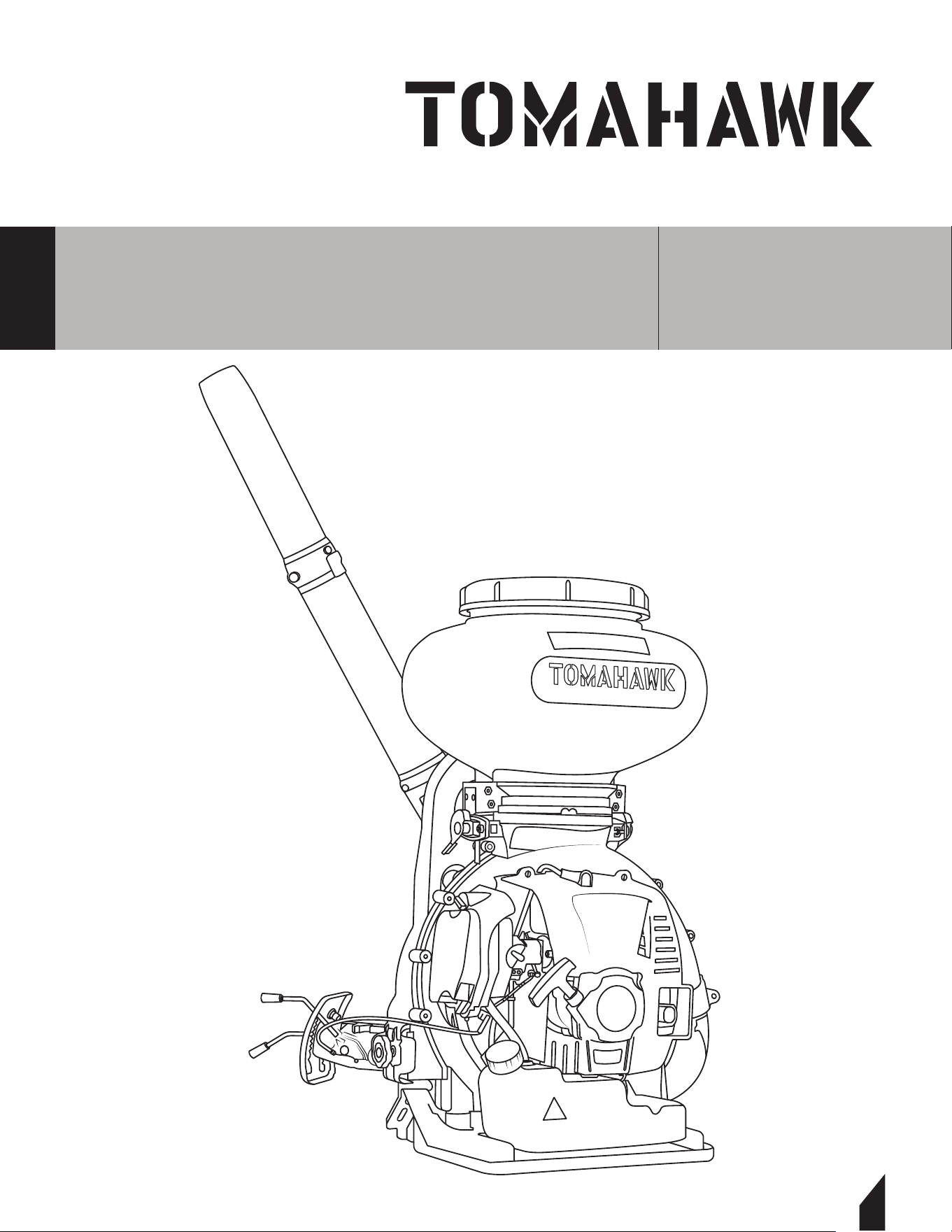
19
Parts Manual
4 GALLON
FERTILIZER SPREADER
MODEL NUMBER: TGS30
20

21
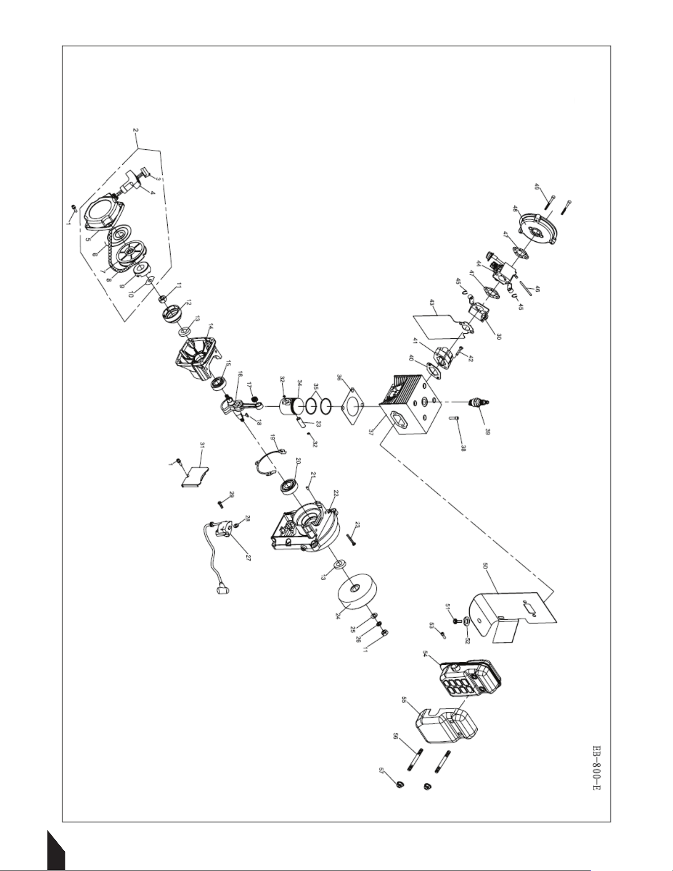
NO. Part NO. Part Name Qty.
1
GB70.1+GB93+GB97 SCREW M5×16 5
2
EB-800-E.1.7 STARTER ASSY 1
3
1E40FP-3Z.4-10 .KNOB CAP 1
4
1E40FP-3Z.4-2 .KNOB 1
5
EB-800-E.1.7-1 .CASE 1
6
1E40FP-3Z.4-7 .SPRING 1
7
EB-800-E.1.7-3 .REEL 1
8
3.8×800 .ROPE 1
9
1E46FP-3.3-1 .WHEEL 1
10
EB-800-E.1.7-2 .GUIDE SLICE 1
11
GB/T 6171 NUT M10×1 2
12
EB-800-E.1.5 START REEL 1
13
1E40FP-3Z-11 SEAL 2
14
1E54FP.2-2 BACK CANKCASE 1
15
GB/T 276 BEARING 6202/P6 1
16
EB-800-E.1.5.1 CRANKSHAFT 1
17
6MF-30.1.4-3 BEARING 1
18
GB 1099 KEY 3×5×13 1
19
1E54FP.2-1 GASKET 1
20
GB/T 276 BEARING 6203 1
21
GB119 PIN 4h8×10 2
22
EB-800-E.1.4-1 FRONT CANKCASE 1
23
GB70 SCREW M5×35 3
24
1E46FP.1.1- FLYWHEEL 1
25
GB97 WASHER 10 1
26
GB93 WASHER 10 1
27
EB-800-E.1.9 MAGNETO 1
28
P40-5 WASHER 2
29
GB9074.13 SCREW M4×20 2
30
EB-800-E.1.10 BLOCK 1
31
EB-800-E.1-3 SHIELD 1
32
1E58FL.6-5 RING 2
33
6MF-30.1.4-2 PISTON PIN 1
34
EB-800-E.1.5-1 PISTON 1
35
1E53FP.4-2 PISTON RING 2
36
EB-800-E.1-7 GASKET 1
37
EB-800-E.1.3 CYLINDER ASSY 1
38
GB70 SCREW M6×20 4
39
BPMR7A SPARK PLUG 1
40
EB-800-E.1-2 GASKET 1
41
EB-800-E.1.2 INSULATOR 1
42
GB70.1+GB93+GB97 SCREW M5×25 2
43
EB-800-E.1-1A GASKET 1
ENGINE GROUP

22
NO. Part NO. Part Name Qty.
1
GB70.1+GB93+GB97 SCREW M5×16 5
2
EB-800-E.1.7 STARTER ASSY 1
3
1E40FP-3Z.4-10 .KNOB CAP 1
4
1E40FP-3Z.4-2 .KNOB 1
5
EB-800-E.1.7-1 .CASE 1
6
1E40FP-3Z.4-7 .SPRING 1
7
EB-800-E.1.7-3 .REEL 1
8
3.8×800 .ROPE 1
9
1E46FP-3.3-1 .WHEEL 1
10
EB-800-E.1.7-2 .GUIDE SLICE 1
11
GB/T 6171 NUT M10×1 2
12
EB-800-E.1.5 START REEL 1
13
1E40FP-3Z-11 SEAL 2
14
1E54FP.2-2 BACK CANKCASE 1
15
GB/T 276 BEARING 6202/P6 1
16
EB-800-E.1.5.1 CRANKSHAFT 1
17
6MF-30.1.4-3 BEARING 1
18
GB 1099 KEY 3×5×13 1
19
1E54FP.2-1 GASKET 1
20
GB/T 276 BEARING 6203 1
21
GB119 PIN 4h8×10 2
22
EB-800-E.1.4-1 FRONT CANKCASE 1
23
GB70 SCREW M5×35 3
24
1E46FP.1.1- FLYWHEEL 1
25
GB97 WASHER 10 1
26
GB93 WASHER 10 1
27
EB-800-E.1.9 MAGNETO 1
28
P40-5 WASHER 2
29
GB9074.13 SCREW M4×20 2
30
EB-800-E.1.10 BLOCK 1
31
EB-800-E.1-3 SHIELD 1
32
1E58FL.6-5 RING 2
33
6MF-30.1.4-2 PISTON PIN 1
34
EB-800-E.1.5-1 PISTON 1
35
1E53FP.4-2 PISTON RING 2
36
EB-800-E.1-7 GASKET 1
37
EB-800-E.1.3 CYLINDER ASSY 1
38
GB70 SCREW M6×20 4
39
BPMR7A SPARK PLUG 1
40
EB-800-E.1-2 GASKET 1
41
EB-800-E.1.2 INSULATOR 1
42
GB70.1+GB93+GB97 SCREW M5×25 2
43
EB-800-E.1-1A GASKET 1
ENGINE GROUP

23
NO. Part NO. Part Name Qty.
44
EB-800-E.1.1 CARBURETOR 1
45
GB 894 RING 8 2
46
CG420.1.3.2-2 FULE TUBE 100mm
47
6MF-30.1-6 GASKET 2
48
EB-800-E.2-7 INSIDE COVER 1
49
GB70.1+GB93+GB97 SCREW M5×80 2
50
EB-800-E.1-4A GASKET 1
51
GB70 SCREW M5×8 1
52
GB96 WASHER 5 1
53
GB70.1+GB93+GB97 SCREW M5×12 1
54
EB-800-E.1.6 MUFFLER 1
55
EB-800-E.1.8 SHIELD 1
56
1E40F-5-13C BOLT 2
57
GB6187.1 NUT M8 2
ENGINE GROUP
24

1525
NO. Part NO. Part Name Qty.
1
3WF-20.9-2 SCREW M5×16 4
2
EB-800-E-4 ENGINE COVER 1
3
3WFB-30.8-1 SUPPORTING PLATE 1
4
EB-415.4.2-2 VITTA PLUG 3
5
EB-500-E.4 FULE TANK ASSY 1
6
EB-500-E.4-1 .FULE TANK 1
7
P40.12.2-3A .FILTER 1
8
CG420.1.3.2-2 .FULE TUBE 350mm
9
EB-415.4.2-4 .FULE TUBE 180mm
10
1E32FL.6.2 .CAP ASSY 1
11
CG420.1.3.2-2 FULE TUBE 100mm
12
EB-415.4.2-4 FULE TUBE 80mm
13
EBV260-3E.1.9.2A JOINT 2
14
GB/T 818 SCREW 6×12 2
15
GB/T 96 WASHER 6 10
16
GB/T 6177 NUT M6 8
17
3WFB-30-5 FRAME BASE 1
18
3F-30.17 SUPPORT COLUMN 2
19
EB-800-E-5 SUPPORT PLATE 1
20
3WF-20A-1 SUPPORT PLATE 1
21
3WF-20.9-1 SCREW 5×10 4
22
GB70.1+GB93+GB848 SCREW 6×25 6
23
3WFB-30.1 FAN ASSY 1
24
EB-650.7-1 .EBLOW 1
25
GB/T 818 .SCREW 5×70 2
26
3WFB-30.1.1 .VOLUTE CASE 1
27
3WFB-30.1.3 .IMPELLER 1
28
3WFB-30.1-1 .SEALING STRIP 1
29
GB/T 845 .SCREW ST4.2×19 10
30
3WFB-30.1.2 .VOLUTE COVER 1
31
GB/T 889.1 .NUT M5 2
32
3WFB-30.3.1 LEAK PIPE ASSY 1
33
3WFB-30.3-1 SEALING WASHER 1
34
3WFB-30.5 RIGHT LOCKING HANDLE ASSY 1
35
3F-30.12 RUBBER PILLAR 2
36
GB/T 5782 SCREW 6×16 4
37
3WFB-30.4 LEFT LOCKING HANDLE ASSY 1
38
GB/T 6170 NUT M6 4
39
GB70.1+GB93+GB97.1 SCREW 5×35-10.9 4
40
3WF-3S.3.1-4 PLASTIC TIE-IN 1
41
3WF-3S.3A PUMP ASSY 1
42
GB9074.4 SCREW 4×10 3
43
GB9074.13 SCREW 6×25 4
TANK AND BLOWER GROUP

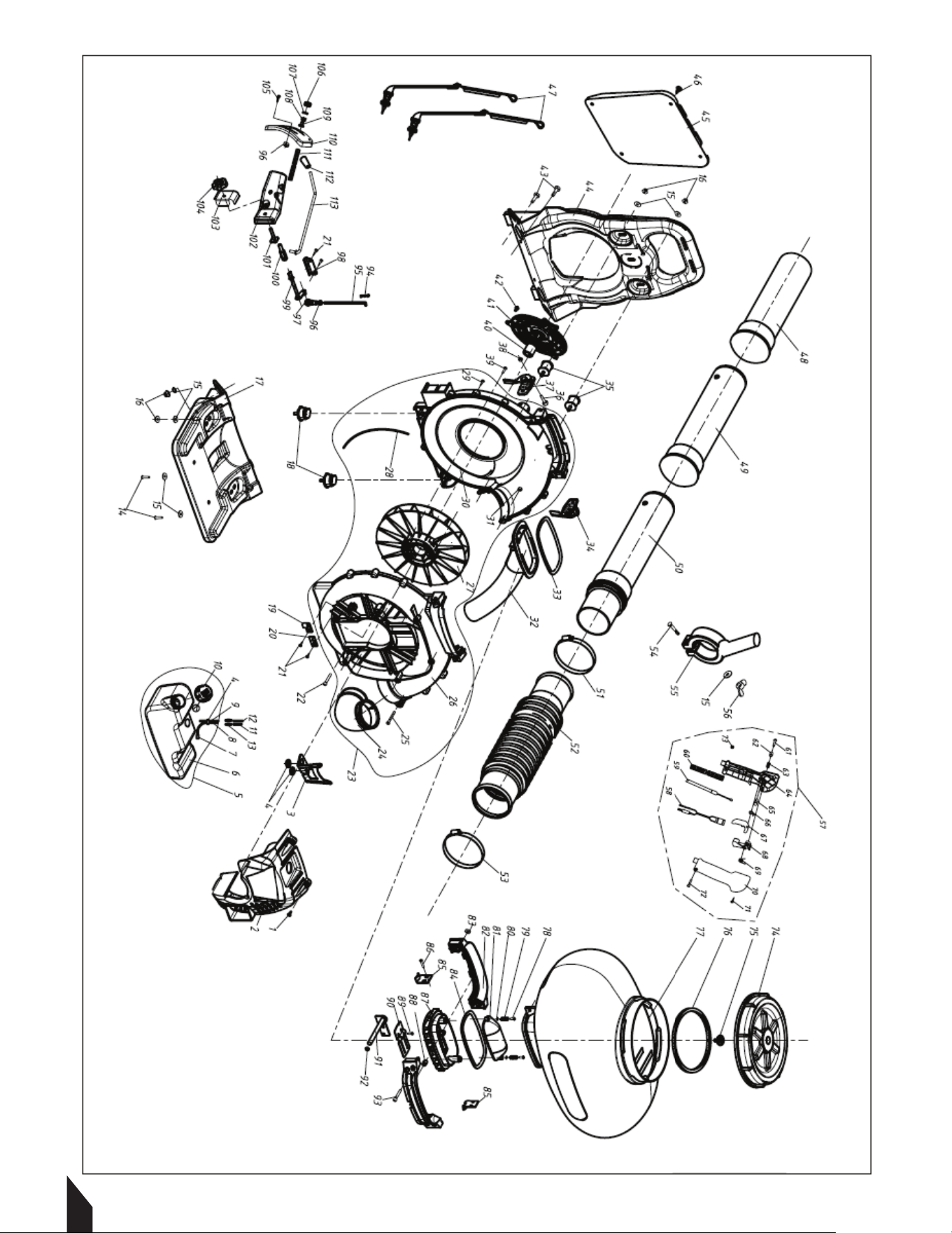
26
NO. Part NO. Part Name Qty.
44
3WFB-30-2 FRAME 1
45
3WFB-30.10 PAD 1
46
3WF-2.6B-2 CLIP 4
47
EB-500-E.3 BAND ASSY 2
48
EB-650-E.5-1 PIPE 1
49
EB-650.7-3 PIPE 1
50
EB-650.7.1 PIPE 1
51
JB8870
φ
59-
φ
82 1
52
3F-30.18-3 HOSE 1
53
JB8870
φ
78-
φ
101 1
54
GB5783 BOLT M6×45 1
55
EB-650.7.2-1A HANDLE 1
56
GB/T 62 NUT M6 1
57
EB-800-E-CZHZZ LEVER SET 1
58
BC36.3.1 .STOP SWITCH 1
59
EB-800-E.6 .CABLE 1
60
3WF-16.3.2-1 .TUBE 1
61
GB/T 846 .SCREW ST2.9×13 1
62
BL750.3-9 .PUSH BUTTION 1
63
BL750.3-7 .SPRING 1
64
CG330B-3E.2.1.2 .LEFT MANIPULATOR 1
65
BL750.3-8 .PIN 1
66
BL750.3-2 .SPRING 1
67
BL750.3-3 .LEVER 1
68
BL750.3-4 .LEVER,throttle 1
69
BL750.3-1 .LONG SPRING 1
70
CG330B-3E.2.1-1 .RIGHT MANIPULATOR 1
71
GB/T 845 .SCREW ST2.9×18 3
72
GB/T 70.1 .SCREW M5×30 1
73
GB/T 889 .NUT M5 1
74
3WF-3.17.1-2 TANK CAP 1
75
3WF-3.17.1-1 AIR VALVE 1
76
3WF-3.17.1-3 SEALING WASHER 1
77
3WFB-30E.1.1-1 CHMICAL TANK 1
78
GB/T 5782 BOLT M6×30 2
79
QWMB12.2.2-5 SPRING 2
80
GB/T97 WASHER 6 2
81
3WFB-30.2.2-4 LEAKPLATE 1
82
3WFB-30.2-1 CLAMP 2
83
GB/T6170 NUT M6 4
84
3WFB-30.2.2-5 SEALING WASHER 1
85
3WFB-30.2-2 FIX PIECE 2
86
GB/T 819 SCREW 5×10 4
87
3WFB-30.2.2-1 DUSTING PLATE 1
88
3WFB-30.3-12 PLUG 1
89
GB/T818 SCREW 4×10 2
TANK AND BLOWER GROUP

27
NO. Part NO. Part Name Qty.
90
3WFB-30.2.2.1 PLATE 1
91
3WFB-30.2.2-3 ROCKER SHAFT 1
92
GB/T 3452.1 SEALING WASHER 6.9×1.8 1
93
GB/T 70.1 SCREW M6×45 4
94
3WF-2.6A-2 PIN 1
95
3WFB-30.7-3 PILLING ROD 1
96
GB/T 6170 NUT M5 3
97
3WF-3-15A CONNECTOR 1
98
3WF-2.6.7-6 PLATE 1
99
3WFB30.7.2 CONNECTING ROD ASSY 1
100
3WFB30.7-2 PIN SHAFT 1
101
3WF-28.3.3 SCREW 1
102
3WFB-30.7-1 CONNECTING BEAM 1
103
3WF-28.3-3 ARMOR PLATE 1
104
3WF-28.1.2 HANDLE 1
105
GB/T 9074.4 SCREW M5×16 2
106
3WF-28.3.4 NUT 1
107
GB/T 97 WASHER 8 1
108
3WF-28.3-8 SPRING 1
109
3WF-28.3-7 SCREW 1
110
3WF-28.3-2 CRADUATOR 1
111
CG328B.1.1-4 TUBE 270mm
112
3F-30.6-2 HANDLE 1
113
3WF-28.3.2 DUST ROD 1
TANK AND BLOWER GROUP

28
The California Air Resources Board, the United States Environmental Protection Agency and
Tomahawk Power, LLC are pleased to explain the emissions control system warranty on your
2023-2024 small engine/equipment (SORE). In the United States and California, new small
engine/equipment must be designed, built and equipped to meet the State's stringent
anti-smog standards. Tomahawk Power, LLC must warrant the emissions control system on
your small engine/equipment for the periods of time listed below provided there has been
no abuse, neglect or improper maintenance of your small engine/equipment.
Your emission control system may include parts such as the carburetor, fuel-injection
system, the ignition system, catalytic convertor, fuel tanks, fuel lines, fuel caps, valves,
canisters, filters, vapor hoses, belts, clamps, connectors, and other associated emission-
related components. For engines less than or equal to 80 cc, only the fuel tank is subject to
the evaporative emission control warranty requirements of this section.
(California Only)
Where a warrantable condition exists, Tomahawk Power, LLC will repair your small off- road
engine/equipment at no cost to you including diagnosis, parts and labor.
MANUFACTURER'S WARRANTY COVERAGE:
The emissions control system is warranted for two years. If any emissions-related part on
your small engine/equipment is defective, the part will be repaired or replaced by
Tomahawk Power, LLC
OWNER'S WARRANTY RESPONSIBILITIES:
As the small engine/equipment owner, you are responsible for the performance of the
required maintenance listed in your owner's manual. Tomahawk Power, LLC recommends
that you retain all receipts covering maintenance on your small engine/ equipment, but
Tomahawk Power, LLC cannot deny warranty solely for the lack of receipts or for your failure
to ensure the performance of all scheduled maintenance.
As the small engine/equipment owner, you should however be aware that Tomahawk Power,
LLC may deny your warranty coverage if your small engine/equipment or a part has failed
due to abuse, neglect, improper maintenance or unapproved modifications.
You are responsible for presenting your small engine/equipment to distribution center or
service center authorized by Tomahawk Power, LLC as soon as the problem exists. The
warranty repairs should be completed in a reasonable amount of time, not to exceed 30
days.

29
If you have any questions regarding your warranty rights and responsibilities, you should
contact Tomahawk Power, LLC customer service representative at 1-866-577-4476 or Email:
support@tomahawk-power.com .
DEFECTS WARRANTY REQUIREMENTS
(a) The warranty period begins on the date the small engine/equipment is delivered to an
ultimate purchaser.
(b) General Emissions Warranty Coverage. Tomahawk Power, LLC warrants to the ultimate
purchaser and each subsequent owner that the engine/equipment is:
(1) Designed, built, and equipped so as to conform with all applicable regulations adopted
by the Air Resources Board; and
(2) Free from defects in materials and workmanship that causes the failure of a warranted
part for a period of two years.
(c) Subject to certain conditions and exclusions as stated below, the warranty on emissions
related parts is as follows:
(1) Any warranted part that is not scheduled for replacement as required maintenance in
your Owner's Manual is warranted for the warranty period stated above. If the part fails
during the period of warranty coverage, the part will be repaired or replaced by Tomahawk
Power, LLC according to Subsection (4) below. Any such part repaired or replaced under
warranty will be warranted for the remainder of the period.
(2) Any warranted part that is scheduled only for regular inspection in your Owner's Manual
is warranted for the warranty period stated above. Any such part repaired or replaced under
warranty will be warranted for the remaining warranty period.
(3) Any warranted part that is scheduled for replacement as required maintenance in your
Owner's Manual is warranted for the period of time before the first scheduled replacement
date for that part. If the part fails before the first scheduled replacement, the part will be
repaired or replaced by Tomahawk Power, LLC according to Subsection (4) below. Any such
part repaired or replaced under warranty will be warranted for the remainder of the period
prior to the first scheduled replacement point for the part.
(4) Repair or replacement of any warranted part under the warranty provisions herein must
be performed at a warranty station at no charge to the owner.
(5) Notwithstanding the provisions herein, warranty services or repair will be provided at all
of our distribution centers that are franchised to service the subject small engine/
equipment.
(6) The small engine/equipment owner must not be charged for diagnostic labor that leads
to the determination that a warranted part is in fact defective, provided that such diagnostic
work is performed at a warranty station.
(7)Tomahawk Power, LLC is liable for damages to other small engine/equipment
components proximately caused by a failure under warranty of any warranted part.

30
(8) Throughout the small engine/equipment warranty period stated above, Tomahawk
Power, LLC will maintain a supply of warranted parts sufficient to meet the expected
demand for such parts.
(9) Any replacement part may be used in the performance of any warranty maintenance or
repairs and must be provided without charge to the owner. Such use will not reduce the
warranty obligations of Tomahawk Power, LLC
(10) Add-on or modified parts that are not exempted by the Air Resources Board may not be
used. The use of any non-exempted add-on or modified parts by the ultimate purchaser will
be grounds for disallowing a warranty claims. Tomahawk Power, LLC will not be liable to
warrant failures of warranted parts caused by the use of a non-exempted add-on or modified
part.
(11) The manufacturer issuing the warranty shall provide any documents that describe that
manufacturer's warranty procedures or policies within five working days of request by the
Air Resources Board.
EMISSION WARRANTY PARTS LIST
The repair or replacement of any warranted part otherwise eligible for warranty coverage
may be excluded from such warranty coverage if Tomahawk Power, LLC demonstrates that
the small engine/equipment has been abused, neglected, or improperly maintained, and
that such abuse, neglect, or improper maintenance was the direct cause of the need for
repair or replacement of the part. That notwithstanding, any adjustment of a component
that has a factory installed, and properly operating, adjustment limiting device is still eligible
for warranty coverage. The following emissions warranty parts for each engine family list is
covered.
For engine families greater than 80cc:
(1) Fuel Metering System:
(a) Gasoline carburetor assembly and its internal components
(b)Carburetor gaskets
(c) Fuel tank
(d) Fuel Line
(e) Fuel Line Fittings
(f) Clamps
(g) Pressure regulator (if equipped)
(h) Mixer assembly and its internal components (if equipped)
(2) Air Induction System including:
(a) Intake pipe/manifold
(b) Air cleaner
(3) Ignition System including:
(a) Spark plug
(b)Ignition coil

(4) Catalytic Muffler Assembly including:
(a) Muffler gasket
(b) Exhaust manifold (c)Catalytic converter
(5) Crankcase Breather Assembly including:
(a) Breather connection tube.
(6) Fuel tank evaporative emissions control system including:
(a) Purge Valves
(b) Carbon Canister
(c) Canister Mounting Brackets
(d) Fuel Cap
(e) Fuel Tank
(7)Miscellaneous items Used in Above Systems including:
(a) Switches
(b) Hoses, belts, connectors, and assemblies.
(8)Air injection system
(a) Pulse valve
For engine families less than or equal to 80cc:
(1) Fuel Metering System:
(a) Gasoline carburetor assembly and its internal components
(b)Fuel filter (if so equipped)
(c) Carburetor gaskets
(d) Fuel pump (if so equipped)
(2) Air lnduction System including:
(a) lntake pipe/manifold
(b) Air cleaner
(3) lgnition System including:
(a) Spark plug (b)lgnition module/coil
(4) Catalytic Muffler Assembly (if so equipped) including:
(a) Muffler gasket
(b) Exhaust manifold
(5) Crankcase Breather Assembly including:
(a) Breather connection tube.
(6) Miscellaneous items Used in Above Systems including:
(a) Switches
(b) Hoses, belts, connectors, and assemblies.
(7) Fuel tank evaporative emissions control system including:
(a) Fuel Tank
The warranty is provided in accordance with the "California AND FEDERAL Emission Control
Warranty Statement".
31

Tomahawk understands to keep a job-site running smoothly the proper equipment and
spare parts are needed at the drop of a hat. With same day shipping and faster
delivery times, count on Tomahawk to keep you powered throughout the day! With
long lasting parts and engines, Tomahawk equipment will be the star of your fleet for
years to come. Visit www.tomahawk-power.com to get started today!
Power Your World
FACEBOOK
facebook.com/TomahawkPowerUSA
YOUTUBE
youtube.com/TomahawkPower
INSTAGRAM
@tomahawkpower
TOMAHAWK®, LLC
San Diego, CA
Sales Support
(866) 577-4476
Equipment Support
(866) 577-4476
www.tomahawk-power.com