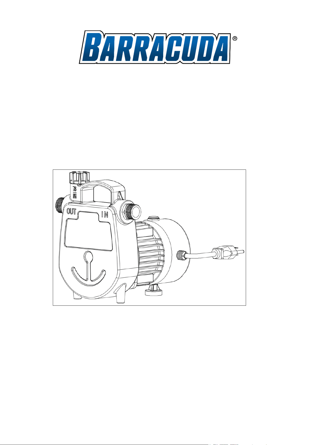
OWNER’S MANUAL
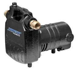
1/2 HP CAST IRON TRANSFER PUMP
SKU# 691-3322
Model# BPUT05002
2
PERFORMANCE
SKU
Model
HP
GPH of Water @ Total discharge pressure psi
Max.
discharge
pressure
0
10
20
30
40
50PSI
691-3322
BPUT05002
1/2 1500 1100 900 650 360
SAFETY INSTRUCTIONS
This pump is non-submersible and should only be used with clear water.
Before start-up:
The pump must be plugged into a GFCI-protected outlet which has been installed according to the National Electric
Code and all local codes. The outlet must have a supply voltage of 120 VAC at 60 Hz.
DANGER
Failure to follow these warnings will result in death or serious injury and/or property damage.
ELECTRICAL SHOCK HAZARD.
This pump is non-submersible. Keep the motor dry at all times. Do not wash the motor or submerse the pump in
water. Protect the motor from wet weather. Do not allow any part of the cord or receptacle ends to sit in water or in
damp locations.
FIRE/EXPLOSION HAZARD.
Pump clear water only with this pump. Do not pump chemicals, corrosive liquids, or flammable or explosive fluids such
as gasoline, fuel oil, kerosene, etc. Do not use in a flammable and/or explosive atmosphere.
WARNING
Hazardous Voltage can shock, burn or cause death.
RISK OF ELECTRIC SHOCK.
1. BE CERTAIN the pump is unplugged before you install, service, or maintain the pump. Never handle a pump
with wet hands or when standing on wet or damp surface or in water.
2. Connect the pump DIRECTLY to a properly grounded 115-volt circuit equipped with a Ground Fault Circuit
Interrupter (GFCI) outlet.
3. Use of an extension cord is not recommended. If the application requires one, it must be an outdoor grade, 16
AWG, or heavier, and no longer than 25’.
4. Before installing this product, have the electrical circuit checked by an electrician to ensure proper grounding.
All electrical installations must conform to the National Electric Code and all local codes.
5. These pumps are supplied with a 3-prong grounded plug to help protect you against the possibility of electrical
shock. DO NOT UNDER ANY CIRCUMSTANCES REMOVE THE GROUND PIN.
6. Protect electrical cord from sharp objects, hot surfaces, oil, and chemicals. Avoid kinking the cord. Replace
the pump if the cord is damaged.
7. Do not lift the pump by the cord. Always use the handle to lift the pump.
3
8. This pump is not intended to be permanently installed outdoors. Protect the pump from extreme heat, cold,
and humidity. This pump is not waterproof and is not intended to be used in showers, saunas, swimming pool
areas, or other potentially wet locations. The motor is designed to be used in a clean, dry location with access
to an adequate supply of cooling air. The ambient temperature around the motor should not exceed 104°F
(40°C).
WARNING
PERSONAL INJURY and/or PRODUCT DAMAGE
1. Do not touch the motor when operating. The motor is designed to operate at high temperatures. Turn the
pump OFF, unplug, and allow the motor to cool before handling.
2. Do not operate this pump while unattended.
3. Never run the pump dry. The pump must be primed before operating.
4. Provide a means of pressure relief if the pump discharge can be shut off or obstructed. Pumps operating with
a closed discharge can create hot liquid, which can cause burns.
5. This pump is equipped with an automatic thermal overload and can restart without warning.
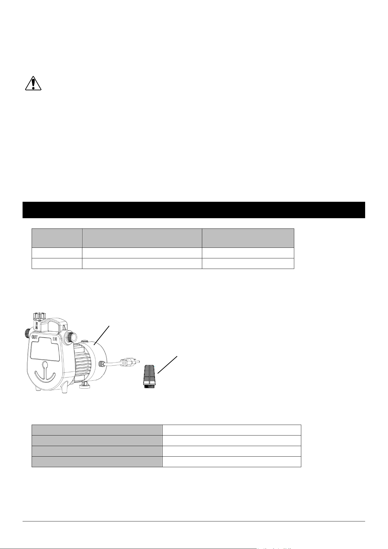
PRE-INSTALLATION
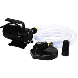
Part DESCRIPTION QUANTITY
A Pump 1
B Hose Strainer 1
SPECIFICATIONS
Horsepower
1/2 HP
Electrical Rating
120VAC / 60Hz / 7A
Power Cord Length
10’
Discharge Port 3/4″ Garden Hose Thread
A
B
4
INSTALLATION
This pump should be located on a solid, stable, and level surface using:
1. ¾” standard garden hose for the INLET line.
2. ¾” standard garden hose for the OULET line.
Please note:
1. Do not hang the pump by the power cord, inlet pipe, or hose. The pump must be placed on a stable surface.
To ensure that the pump works properly, keep the suction end of the hose or pipe free from debris and
sludge.
2. If the water level is too low, any debris or sludge will dry out and stop the pump from starting. To ensure the
pump will start as required, check the pump regularly with start-up tests.
Areas of use
1. This pump is designed to pump water only.
2. This pump can be used for general-purpose removal or transfer of clear water in household and farming
applications.
3. DO NOT use this pump for continuous run applications, fountain or pond water features, emptying swimming
pools or spas, or with septic and sewage systems.
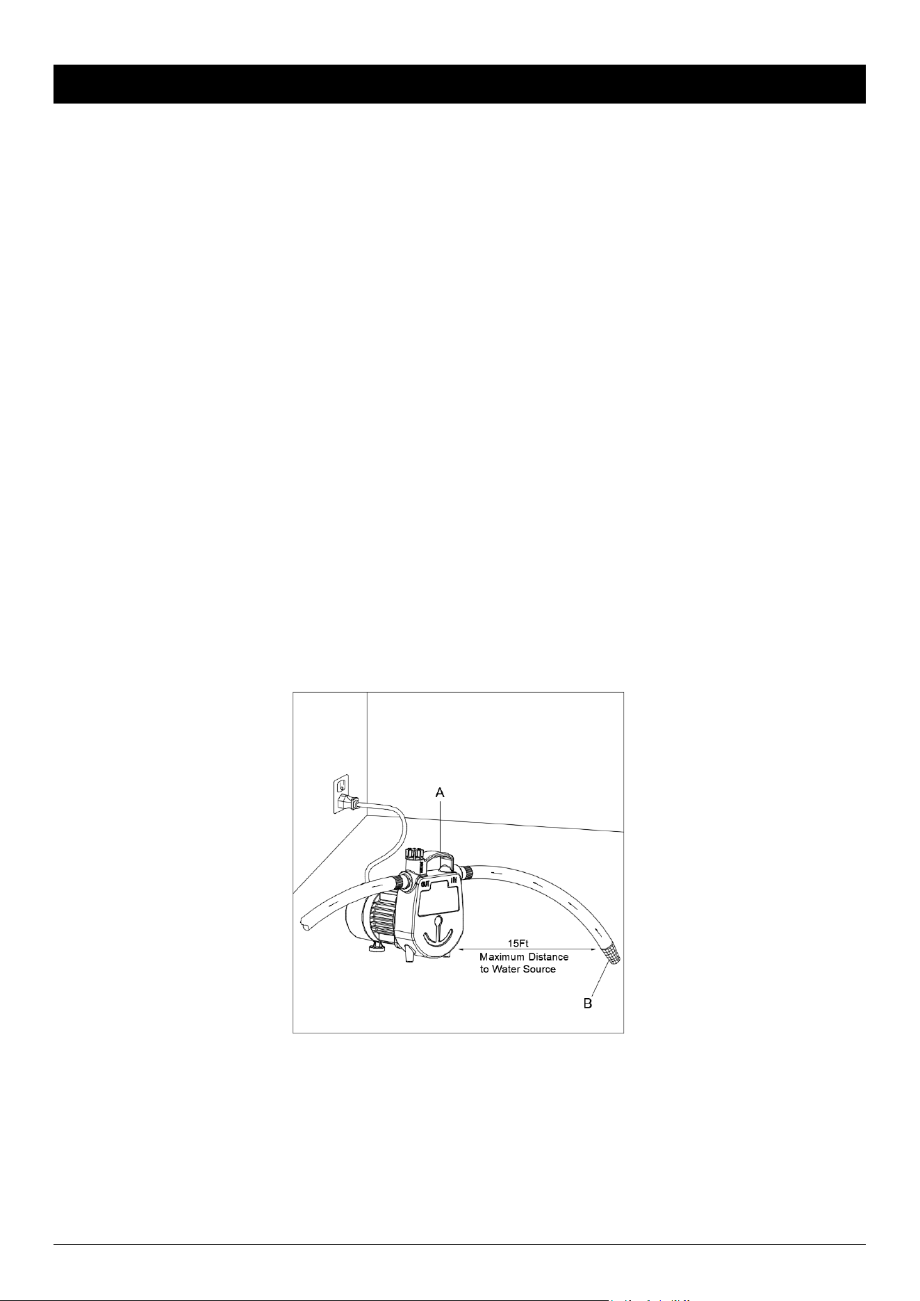
LOCATION
Pump (A) should be located within 15 ft. of the water source, and strainer (B) should be used at the end of the inlet
line. NOTE: Make sure the inlet hose is NOT coiled or kinked above or below the water level. Be sure there are no
leaks in the inlet line, as this may reduce pump efficiency or prevent priming. The inlet line should be the same
diameter as the discharge line, or larger. Keep the total length as short as possible for best performance.
5
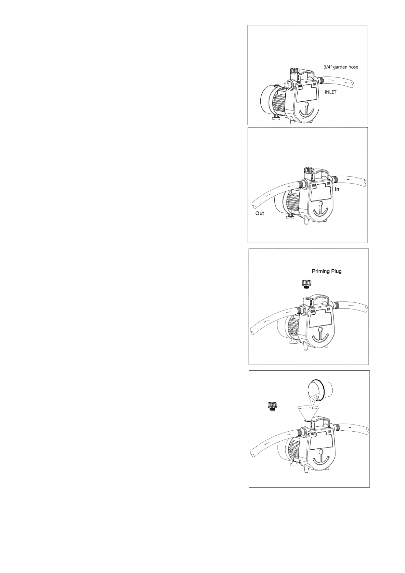
INSTALLATION INSTRUCTIONS
1. Attach a standard 3/4” garden hose to the INLET on the
pump, making sure the connection is airtight. Attach the
hose strainer to the other end of the garden hose to prevent
debris from entering the pump.
2. Attach a standard 3/4” garden hose to the OUTLET on the
pump. Keep the total length of hose as short as possible for
best performance. Secure the hose to keep it from moving
around.
3. Remove priming plug from the top of the pump.
4. Fill pump housing with clean water. Reinstall plug.
DO NOT RUN DRY.
NOTE: Do not pump sand or other abrasives as this will
damage the shaft seal or impeller and void the warranty.
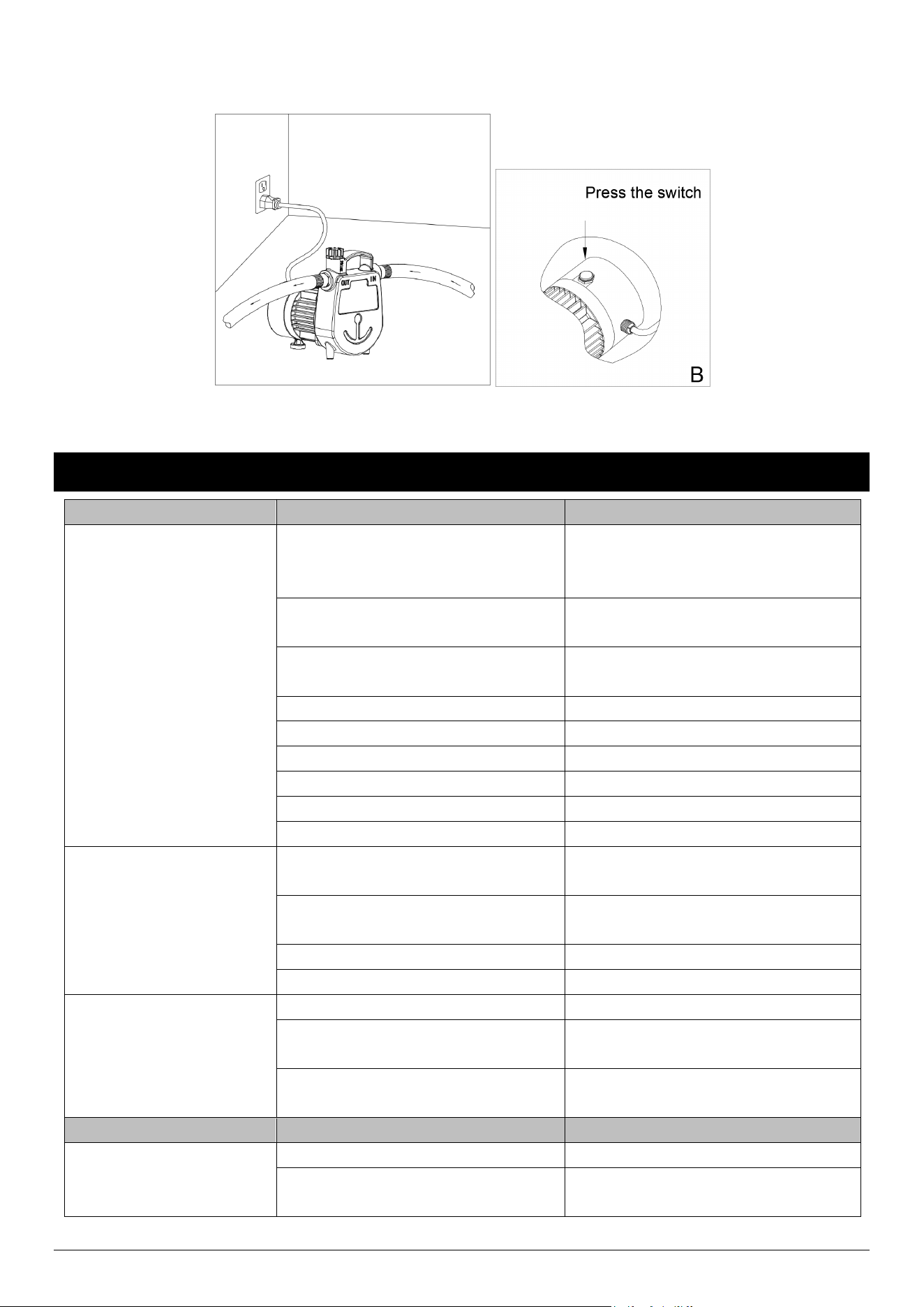
5. For normal water transfer applications, plug in power cord to grounded outlet. Then press the switch on
the top of the motor (B). Pump will prime in a few minutes, depending on suction line length.
Description of the switch: After connecting the plug, you must press the switch to start the pump. When you
6
stop using it, you need to press the switch again to turn off the pump or unplug the plug directly. Repeat the
above operation next time you use it.
6. If the pump does not pump water after two minutes, turn off the pump and repeat steps 4 through 6.
DO NOT RUN DRY.
TROUBLESHOOTING
PROBLEM
POSSIBLE CAUSE
CORRECTIVE ACTION
Pump will not begin
pumping or retain prime
after operating, or stops
pumping water.
1. Air leak in suction line. 1. Repair or replace suction line. Make
sure fittings are air tight and use
thread sealant tape if necessary.
2. Fittings are not tight. 2. Tighten fittings air tight, using
thread sealant tape if necessary.
3. Hose is kinked or looped. 3. Inspect hose and straighten if
needed.
4. Inlet hose is out of the water.
4. Submerge inlet hose end.
5. Clogged inlet.
5. Clean inlet.
6. Inlet lift too high.
6. Lower pump.
7. Impeller blocked. 7. Remove blockage.
8. Worn seal. 8. Replace seal.
9. Collapsed inlet hose. 9. Replace with reinforced hose.
Pump will not start or run.
1. Blown fuse or circuit breaker. 1. If blown, replace with proper sized
fuse or reset breaker.
2. Low line voltage. 2. If voltage is under 104 volts, check
wiring size.
3. Impeller blocked.
3. Remove blockage.
4. Defective motor.
4. Replace pump.
Flow rate is too low.
1. Hose is kinked or damaged.
1. Clean or replace hose.
2. Low line voltage. 2. If voltage is under 104 volts, check
wiring size.
3. Too much discharge hose friction.
3. Shorten and/or increase the
diameter of the discharge hose.
PROBLEM
POSSIBLE CAUSE
CORRECTIVE ACTION
Seal leaks
1. Worn seal.
1. Replace seal.
2. Pump head is loose on motor.
2. Ensure proper assembly and check
for obstructions. Tighten bolts.
7
The pump stops during
work
1. Insufficient water source leads to
no-load protection
1. Check the water source and restart
the pump according to the operation
steps
2. The impeller is locked by garbage
2. Remove the pump body and clean
up the garbage
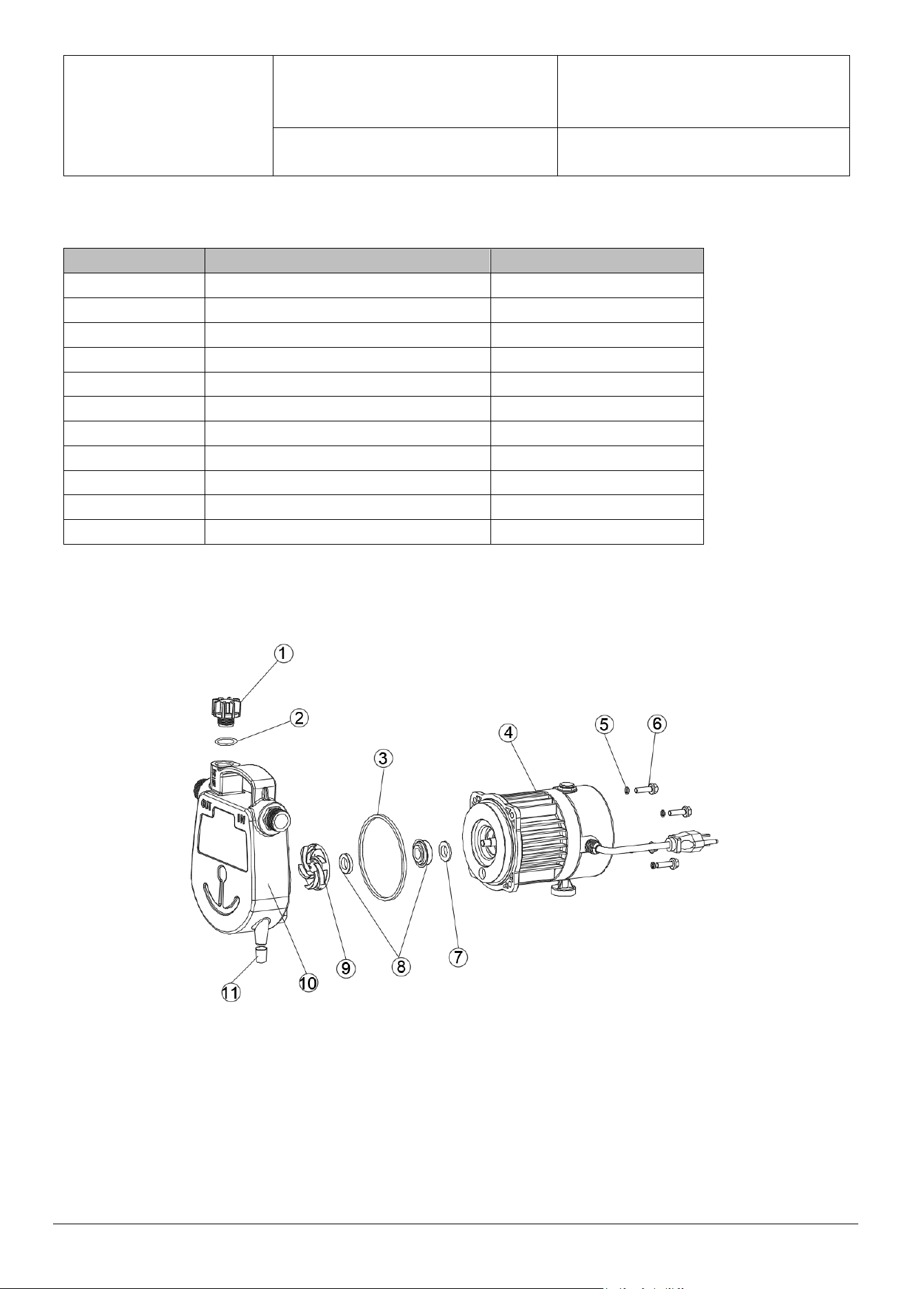
Parts List
Part
Description
Qty.
1
Priming Plug
1
2
O-ring
1
3
Pump Gasket
1
4
Motor
1
5
Spring Washer
4
6 Screw 4
7 Water Retaining Washer 1
8 Mechanical Seal 1
9 Impeller 1
10
Pump Facing
1
11
Rubber Foot
2
Assembly Diagram

8
BARRACUDA® LIMITED WARRANTY
WHAT THIS WARRANTY COVERS
Barracuda warrants to the original consumer purchaser (You) that its products are free from original defects
in material and workmanship for one year (warranty varies depending on model; see box or BARRACUDA
website for specific warranty informa�on) from the date of purchase (the Warranty Period). Repair parts
and accessories are warranted for 90 days from the date of purchase. During the Warranty Period,
BARRACUDA will repair or replace, at no cost to you, products that have been examined by BARRACUDA
and found to be defec�ve in materials or workmanship.
WHAT THIS WARRANTY DOES NOT COVER
This Warranty does not cover use of the product in a non-residen�al applica�on, improper installa�on
and/or maintenance of the product, damage due to misuse, acts of God, nature, vandalism, or other acts
beyond control of BARRACUDA, owner’s acts or omissions, use outside the country in which the product
was ini�ally purchased and resale of the product by the original owner. This warranty does not cover pick-
up, delivery, transporta�on, or house calls. However, if you mail your product to a BARRACUDA Sales and
Service Center for warranty service, cost of shipping will be paid one way. This warranty does not apply to
products purchased outside the United States, including its territories and possessions, outside of U.S.
Military Exchange and outside of Canada. This warranty does not cover products purchased from a party
that is not an authorized retailer, dealer, or distributor of BARRACUDA products.
OTHER IMPORTANT TERMS
This warranty is not transferable and may not be assigned. This Warranty shall be governed and construed
under laws of the state of Michigan. The Warranty Period will not be extended by any replacement or
repair performed under this Warranty. THIS WARRANTY IS THE EXCLUSIVE WARRANTY AND REMEDY
PROVIDED BY BARRACUDA. ALL OTHER WARRANTIES, EXPRESSED OR IMPLIED, INCLUDING WARRANTIES OR
MERCHANTABILITY OR FITNESS FOR PARTICULAR PURPOSE, ARE DISCLAIMED. IN NO EVENT WILL
BARRACUDA BE LIABLE FOR ANY SPECIAL, INDIRECT, INCIDENTAL, OR CONSEQUENTIAL DAMAGES OF ANY
KIND OR NATURE TO OWNER OR ANY PARTY CLAIMING THROUGH OWNER WHETHER BASED IN CONTRACT,
NEGLIGENCE, TORT, OR STRICT PRODUCTS LIABLITY OR ARISING FROM ANY CAUSE WHATSOEVER. Some
states do not allow for the exclusion of consequen�al damages, so the above exclusion may not apply to
you. This warranty gives you specific rights. You may also have other rights that vary from state to state.
For technical support and parts, call Customer Service at 844-242-2475.