1
35
2
7
9
30
(2x)
15
(2x)
11
(17x)
11
(4x)
13
32
14
15
(4x)
33
5
(2x)
10
(4x)
16
29
19 (2x)
18 (2x)
17 (2x)
26
28
15
(9x)
25
23
22
27
21
20
45
43 / 44
46
47
43/44
8
42
12
6
4
(2x)
3
(2x)
49
48
20 21
22 23
27 33
55
18 19
53
2 3 4 5
6 7 11 13
15 16 17 19
20 21 22 23
25 27 28 30
32 33 42 49
52
11 13
32 42
54
15 26
28 29
56
43 45
58
44 45
59
9 10
11 12
46 47
48
57
BULLETIN NO.
PN0007993
SERVICE PARTS LIST
CATALOG NO.
REVISED BULLETIN
SPECIFY CATALOG NO. AND SERIAL NO. WHEN ORDERING PARTS
M12™ Wireless Monitor
(Borescope Pipeline Viewer)
SERIAL NO.
DATE
July 2025
WIRING INSTRUCTION
P39A
See Page 2
MILWAUKEE TOOL
l
www.milwaukeetool.com
13135 W. LISBON RD., BROOKFIELD, WI 53005
Drwg. 2
FIG. SERVICE NOTES
36
A clean, dry surface is essential for proper performance for any
adhesive system. The area intended for application of any
adhesive label or nameplate must be prepared by cleaning with
isopropyl alcohol. The solvent is to be applied with a clean, lint
free applicator and the surface allowed to dry before applying
the label or nameplate.
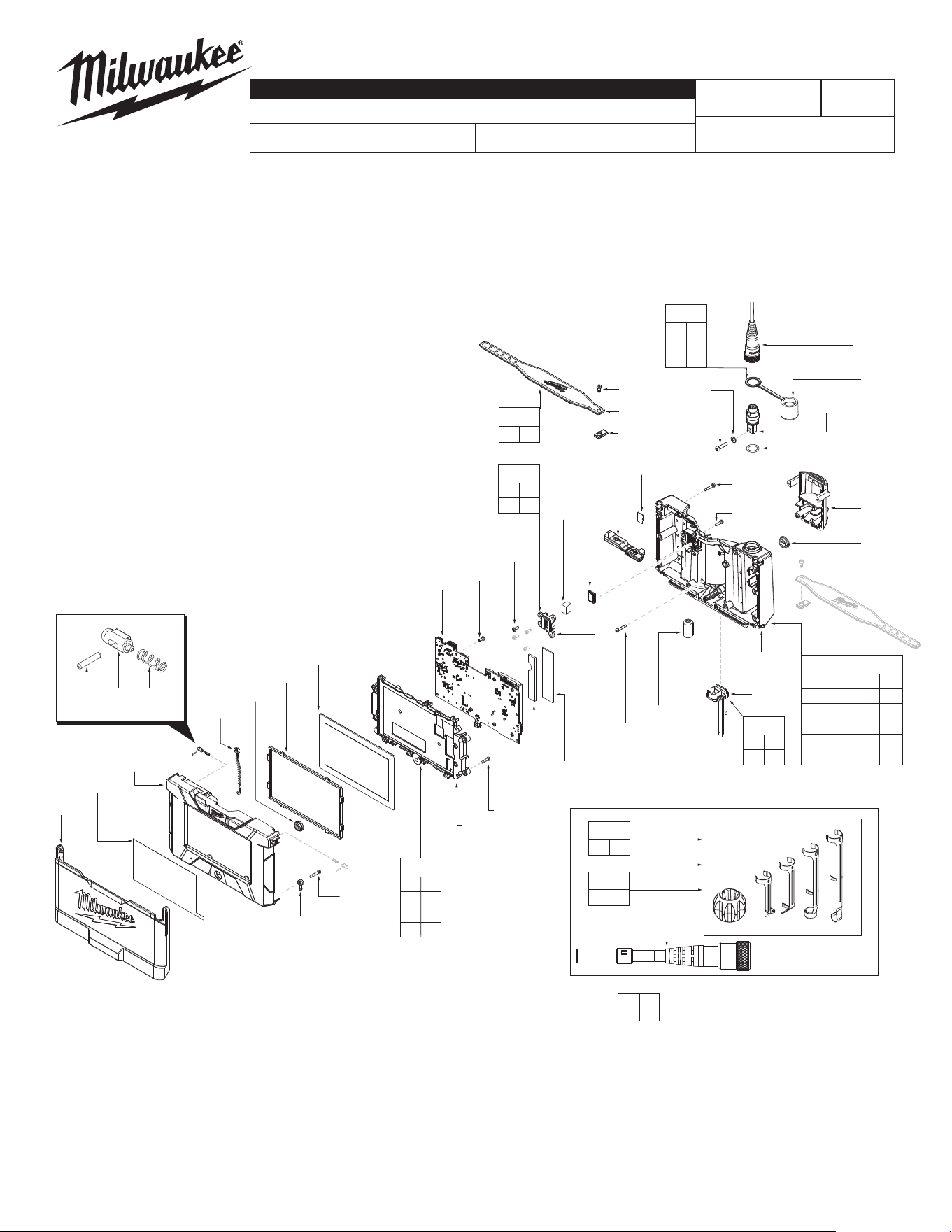
FIG. PART NO. DESCRIPTION OF PART NO. REQ.
1 31-15-0242 Sunshade (1)
2 --------------- Handle Support (1)
3 --------------- Spring (2)
4 --------------- Detent Ball (2)
5 --------------- Pin (2)
6 --------------- Power Button (1)
7 --------------- Screen Gasket (1)
8 44-06-0097 LCD (1)
9 --------------- LCD Screen Holder (1)
10 06-82-1087 M3 x 12mm Screw (4)
11 06-82-0027 M3 x 7mm Pan Head T-10 B Screw (21)
12 --------------- PCBA (1)
13 --------------- Speaker Cover (1)
14 31-15-0243 Rubber Cover - USB Connector (1)
15 06-82-6351 M3 x 16mm Pan Hd Torx T-10 Screw (15)
16 --------------- Handle Cover (1)
17 --------------- Strap Pin Block (2)
18 --------------- Silicone Strap (2)
19 05-89-0100 M3 x 7mm Hexagon M Screw (2)
20 06-82-1076 M4 x 16mm Pan Hd Torx T-20 B Screw (1)
21 --------------- Flat Washer (1)
22 --------------- Camera Connector Assy-Female (1)
23 31-15-0244 Cap for Camera Connector (1)
25 05-81-0005 M3 x 11mm T-10 Taptite Screw (1)
26 --------------- Main Battery Interface (1)
27 --------------- O-Ring (1)
28 --------------- Rubber Seal for Terminal (1)
29 --------------- Terminal Block Assy (1)
30 --------------- Strap Pin (2)
32 --------------- Foam Speaker Pad (1)
33 --------------- Ferrite Core (1)
35 --------------- Screen Label (1)
36 12-20-0914 Service Nameplate
(Not Shown)
(1)
39 45-96-0290 Hexagon Wrench 2.5mm
(Not Shown)
(1)
41 42-44-0715 6 FT USB C to USB C Cable
(Not Shown)
(1)
42 --------------- Speaker (1)
43 --------------- 10mm 4 FT Camera Module (1)
44 --------------- 10mm 10 FT Camera Module (1)
45 14-38-0454 10mm Camera Head Accessory (1)
46 --------------- Big Thermal Pad (1)
47 --------------- Small Thermal Pad (1)
48 --------------- SD Card (1)
49 --------------- Microphone Assy (1)
48 --------------- SD Card (1)
49 --------------- Microphone Assy (1)
52 14-38-0191 Housing Kit (1)
FIG. PART NO. DESCRIPTION OF PART NO. REQ.
3971-20
FIG. PART NO. DESCRIPTION OF PART NO. REQ.
53 14-46-0391 Strap Kit (1)
54 14-46-0389 Speaker Kit (1)
55 14-46-0388 Camera Connector Kit (1)
56 14-38-0193 Battery Housing Kit (1)
57 14-20-0318 Electronics Assembly (1)
58 48-53-3315
10mm 4 FT Camera Module Kit
(Accessory)
(1)
59 48-53-3316
10mm 10 FT Camera Module Kit
(Accessory)
(1)
65 48-53-3151
5mm 5 FT Replacement Cable
(Not Shown, Accessory)
(1)
EXAMPLE:
Component Parts (Small #) Are Included
When Ordering The Assembly (Large #).
0
00
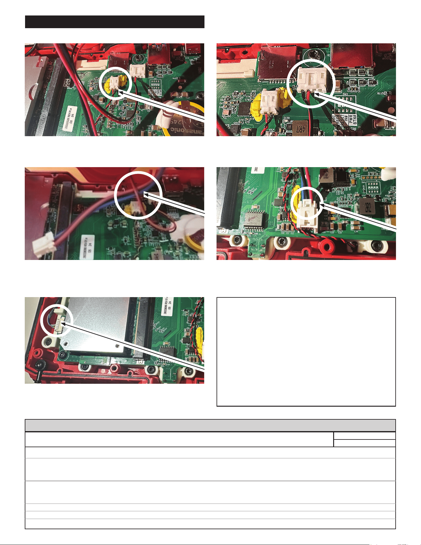
WIRING INSTRUCTIONS
3) Make sure the Battery Terminal Block Wire goes
under the Speaker Wire. (This ensures the wires will
not get caught in the screw area.)
4) Plug the Battery Terminal into the battery socket.
5) Plug the Cable Terminal into the cable socket. Clamp
the camera wire into the housing bone to avoid the
screw bosses.
WARNING
• Take notice of wire routing and position in wire
guides and traps while dismantling tool.
• Be sure that all components of the electronics kit
are seated rmly and squarely in housing recesses.
• Avoid pinched wires, be sure all wires and sleeves are
pressed completely down in wire guides and traps.
• Prior to installing housing cover onto handle support,
be sure that there are no interferences.
• Be sure to check for C functionality of switches and
buttons after housing halves have been secured.
SEAT TORQUE
FIG. PART NO. DESCRIPTION OF FASTENER QTY WHERE USED (kgf-cm) (lb-in)
10 06-82-1087 M3 x 12mm Screw 4 LCD Screen Holder 9 ± 1 9 ± 1
11 06-82-0027 M3 x 7mm Pan Head T-10 B Screw 11 LCD Screen Holder 4 ± 1 3 ± 1
4 Speaker Cover 4 ± 1 3 ± 1
6 PCBA 6 ± 1 5 ± 1
15 06-82-6351 M3 x 16mm Pan Hd Torx T-10 Screw 9 Handle Cover 9 ± 1 8 ± 1
4 Main Battery Interface 9 ± 1 8 ± 1
2 Strap Pin 9 ± 1 8 ± 1
19 05-89-0100 M3 x 7mm Hexagon M Screw 2 Strap 4 ± 1 3 ± 1
20 06-82-1076 M4 x 16mm Pan Hd Torx T-20 B Screw 1 Camera Connector Assy-Female 12 ± 1 10 ± 1
25 05-81-0005 M3 x 11mm T-10 Taptite Screw 1 Handle Cover 6 ± 1 5 ± 1
SCREW TORQUE SPECIFICATIONS
1) Plug the Microphone Terminal into the microphone
socket.
2) Plug the Speaker Terminal into the speaker socket.