
YEAR
W
A
R
R
A
N
T
Y
Honda Engine
on
3
HOW TO VIDEOS, MANUALS,
FINISHING GUIDES, & MORE
TPT36H, TPT46H-270, TPT46H-390
POWER TROWEL
Operation Manual

2
TABLE OF CONTENTS
1. Safety Information
2. General Information
3. Technical Data
4. Quick Start Guide
5. Controls and Components
6. Engine
7. Pre-Inspection
8. Initial Start Up
9. Starting the Engine
10. Stopping the Engine
11. Operation
12. Accessory Options
13. Maintenance
14. Training Checklist
15. Parts List
16. Catalog and Coupon
4
7
9
10
11
13
15
17
18
19
22
23
24
28
29
42

3
Register Your Equipment
Thank you for purchasing TOMAHAWK equipment! Your product is covered by the
TOMAHAWK Warranty policy, but in order to activate your warranty, we need you to register
your product. In addition to activating your equipment warranty, product registration will
grant you access to important product updates, streamlined customer service and more.
INCLUDED WITH YOUR REGISTRATION
☑ Equipment Warranty Activation
☑ Product Updates
☑ Streamlined Customer Service
☑ Excusive Discounts and Sales
STEPS TO REGISTER YOUR EQUIPMENT
1. Visit www.tomahawk-power.com
2. Choose “Product Registration” at the bottom of the page
3. Enter your equipment’s serial number to get started
4. Provide all required information
5. Submit Registration
Equipment Resources
Tomahawk Customer Service doesn’t stop at checkout. We understand to keep a job-site
running smoothly - the proper equipment, spare parts, instruction manuals, and more are
needed at the drop of a hat. Visit www.tomahawk-power.com to gain access to the incredible
resources below.
How To Video Library
More of a visual person? Visit our Video Library for equipment
assembly instructions, troubleshooting tips, and more!
Found on each product listing or the Service Videos Page
Manual and Assembly Guide Library
Visit our Manual Library if you are looking for a lost
operations manual or a particular spare part?
Found on each product listing or the Tomahawk Manuals Page
Service Requests
In need of a quick fix or a service center referral? Submit a
Service Request and a Tomahawk Technician will respond
shortly to get you the help you need.
Choose “Service Request” at the bottom of www.tomahawk-power.com

This manual provides information and procedures to safely operate and maintain this
equipment. For your own safety and protection from injury, carefully read, understand and
observe the safety instructions described in this manual.
Keep this manual or a copy of it with the equipment. If you lose this manual or need an
additional copy, please contact Tomahawk Power LLC or visit www.tomahawk-power.com
This equipment is built with user safety in mind; however, it can present hazards if
improperly operated and serviced. Follow operating instructions carefully. If you have
questions about operating or servicing this equipment, contact Tomahawk Power.
The information contained in this manual is based on equipment’s production at the time of
publication. Tomahawk Power reserves the right to change any portion of this information
without notice.
No part of this publication may be reproduced in any form or by any means, electronic or
mechanical, including photocopying, without express written permission from
Tomahawk Power.
Any type of reproduction or distribution not authorized by Tomahawk Power represents an
infringement of valid copyrights and will be prosecuted. We expressly reserve the right to
make technical modifications, even without due notice, which aim at improving our
machines or their safety standards.
1. SAFETY INFORMATION
This manual contains DANGER, WARNING, CAUTION, and NOTE callouts which must be
followed to reduce the possibility of personal injury, damage to the equipment, or improp-
er service.
This is the safety alert symbol. It is used to alert you to potential personal injury
hazards. Obey all safety messages that follow this symbol to avoid possible injury
or death.
DANGER indicates an imminently hazardous situation which, if not avoided, will
result in death or serious injury.
WARNING indicates a potentially hazardous situation which, if not avoided, could
result in death or serious injury.
CAUTION indicates a potentially hazardous situation which, if not avoided, may
result in minor or moderate injury.
DANGER
WARNING
CAUTION
4

5
CAUTION: Used without the safety alert symbol, CAUTION indicates a potentially
hazardous situation which, if not avoided, may result in property damage.
1.1 Laws Pertaining to Spark Arresters
Notice: State Health Safety Codes and Public Resources Codes specify that in certain
locations spark arresters be used on internal combustion engines that use hydrocarbon
fuels. A spark arrester is a device designed to prevent accidental discharge of sparks or
flames from the engine exhaust. Spark arresters are qualified and rated by the United
States Forest Service for this purpose.
In order to comply with local laws regarding spark arresters, consult the engine distributor
or the local Health and Safety Administrator.
1.2 Operating Safety
Familiarity and proper training are required for the safe operation of equipment!
Equipment operated improperly or by untrained personnel can be dangerous! Read
the operating instructions contained in both this manual and the engine manual and
familiarize yourself with the location and proper use of all controls. Inexperienced
operators should receive instruction from someone familiar with the equipment before
being allowed to operate the machine.
1.2.1 NEVER allow anyone to operate this equipment without proper training. People
operating this equipment must be familiar with the risks and hazards associated with it.
1.2.2 NEVER touch the engine or muffler while the engine is on or immediately aer it has
been turned off. These areas get hot and may cause burns.
1.2.3 NEVER use accessories or attachments that are not recommended by Tomahawk
Power. Damage to equipment and injury to the user may result.
1.2.4 NEVER leave machine running unattended.
1.2.5 ALWAYS be sure operator is familiar with proper safety precautions and operation
techniques before using machine.
1.2.6 ALWAYS wear ANSI Z87.1-approved safety goggles or safety glasses with side shields,
or when needed, a face shield. Use a dust mask in dusty work conditions. Also use non-skid
safety shoes, hardhat, gloves, dust collection systems, and hearing protection when
appropriate. This applies to all persons in the work area.
1.2.7 ALWAYS close fuel valve on engines equipped with one when machine is not being
operated.
1.2.8 ALWAYS store equipment properly when it is not being used. Equipment should be
stored in a clean, dry location out of the reach of children.
WARNING

6
1.2.9 ALWAYS operate machine with all safety devices and guards in place and in working
order. DO NOT modify or remove safety devices. DO NOT operate machine if any safety
devices or guards are missing or inoperative.
1.2.10 ALWAYS read, understand, and follow procedures in Operator's Manual before
attempting to operate equipment.
1.3 Safety while using Combustion Engines
Internal combustion engines present special hazards during operation and fueling!
Read and follow warning instructions in engine owner's manual and safety guidelines
below. Failure to follow warnings and DANGER safety guidelines could result in severe
injury or death.
1.3.1 DO NOT run machine indoors or in an enclosed area such as a deep trenches unless
there is adequate ventilation, through such items as exhaust fans or hoses are provided.
Gasoline exhaust from the engine contains poisonous carbon monoxide gas; exposure to
carbon monoxide can cause loss of consciousness and may lead to death.
1.3.2 DO NOT smoke while operating machine.
1.3.3 DO NOT smoke when refueling engine.
1.3.4 DO NOT refuel hot or running engine.
1.3.5 DO NOT refuel engine near open flame.
1.3.6 DO NOT spill fuel when refueling engine.
1.3.7 DO NOT run engine near open flames.
1.3.8 ALWAYS refill fuel tank in well-ventilated area.
1.3.9 ALWAYS replace fuel tank cap aer refueling.
1.3.10 ALWAYS check fuel lines and fuel tank for leaks and cracks before starting engine.
1.3.11 DO NOT run machine if fuel leaks are present or fuel lines are loose.
1.4 Service Safety
Poorly maintained equipment can become a safety hazard! In order for the
equipment to operate safely and properly over a long period of time, periodic
maintenance and occasional repairs are necessary.
1.4.1 DO NOT attempt to clean or service machine while it is running. Rotating parts can
cause severe injury.
1.4.2 DO NOT crank a flooded engine with the spark plug removed on gasoline-powered
engines. Fuel trapped in the cylinder will squirt out the spark plug opening.
DANGER
WARNING

7
1.4.3 DO NOT test for spark on gasoline-powered engines, if engine is flooded or the smell
of gasoline is present. A stray spark could ignite fumes.
1.4.4 DO NOT use gasoline or other types of fuels or flammable solvents to clean parts,
especially in enclosed areas. Fumes from fuels and solvents can become explosive.
1.4.5 ALWAYS keep area around muffler free of debris such as leaves, paper, cartons, etc. A
hot muffler could ignite them, starting a fire.
1.4.6 ALWAYS replace worn or damaged components with spare parts designed and
recommended by Tomahawk Power.
1.4.7 ALWAYS disconnect spark plug on machines equipped with gasoline engines, before
servicing, to avoid accidental start-up.
1.4.8 ALWAYS keep machine clean and labels legible. Replace all missing and hard-to-read
labels. Labels provide important operating instructions and warn of dangers and hazards.
1.4.9 ALWAYS check for damaged parts before each use. Carefully check that the trowel
will operate properly and perform its intended function. Replace damaged or worn parts
immediately. Never operate the trowel with a damaged part.
1.4.10 ALWAYS inspect the screed prior to placing in storage and before re-use. Store the
trowel in a dry, secure place out of the reach of children when not in use.
1.4.11 ALWAYS use only accessories that are recommended by the manufacturer for use
with the trowel . Accessories that may be suitable for one trowel may create a risk of injury
when used with the screed equipment.
1.4.12 ALWAYS keep blades clean when not in use and guards in place and in working
order.
2. GENERAL INFORMATION
2.1 Intended Use
Leave laborious hand-finishing tasks in the past with the Tomahawk Power Trowels!
Densify concrete floors with ease for your ideal finishing results on projects including
driveways, basements, and commercial/industrial jobs.
2.2 Trowel Familiarization
Tomahawk Power Trowels are designed for the floating and finishing of concrete slabs.
Analyze your trowel and take notice of each component: the engine, blades, quick pitch
control, air cleaner, centrifugal stop switch, clutch and pulley system. Be sure that there is
always oil in the engine.

8
2.3 Safety
Before using your power trowel, read all of the safety instructions carefully. Safety
instructions are available throughout this manual and on the equipment. Safety
information should remain in good, readable condition. Operators must be well trained on
the operations and maintenance of the trowel.
Before starting, test the trowel on a flat, watered down section of finished concrete. Test on
a section that is free of any debris and other objects.
The trial test run will increase operator confidence, while helping familiarize yourself with
the trowel’s controls. In addition, this will help operators understand how the power trowel
functions under real conditions.
2.4 Engine
Tomahawk Power Trowels are powered by Honda and Kohler Engines. Refer to the engine
owner’s manual for instructions regarding the operation and maintenance of your engine.
The engine manual is included with your trowel. For further assistance or to receive a new
manual, contact Tomahawk Power customer service at (866) 577-4476 or refer to the
Manuals Page on the Tomahawk Power website.
2.5 Drive System
The power is transferred from the engine to the gearbox input sha via a V-belt pulley drive
system. The pulley engages using either a centrifugal or manual clutch. Refer to the Parts
section of this manual for more information.
2.6 Gearbox
The gearbox is located beneath the engine and transfers power to the rotor or spiderbox
assembly. The gearbox controls the rotational speed of the trowel and is equipped with two
shas (input and output).
2.7 Spiderbox
The vertical output sha of the gearbox connects to a cast hub called the spiderbox. The
spiderbox has 4 arms that extend outward that are used for attachment of blades or other
accessories. Remember: when the gearbox output sha rotates, so does the spiderbox
assembly.
2.8 Guard Ring
Some units are equipped with a special rotating guard ring. It is designed to allow the
operator to run the machine alongside walls, pipes, and obstructions without marring the
surface.

9
2.9 Blades
The blades of the trowel are used to finish the concrete as they rotate around your given
surface. This trowel includes 4 combination blades (8 in./203mm wide) per rotor. They are
equally spaced in a radial pattern and attached to the vertical rotating sha by means of the
spider assembly.
2.10 Centrifugal Clutch
In the event of a trowel runaway condition (the operator releases the handle), the centrifugal
clutch will stop the engine and bring the trowel to a complete stop.
2.11 Training
For proper training education, refer to the “TRAINING CHECKLIST” section located in the
back of this manual. This checklist contains an outline for an experienced operators to
provide training to a new operator.
3. TECHNICAL DATA
MODEL TPT36H TPT46H-270 TPT46H-390
Number of Blades 4 4 4
Ring Diameter 36.0 in. (91 cm.) 46.0 in. (116 cm.) 46.0 in. (116 cm.)
Rotor 70-130 RPM 70-130 RPM 70-130 RPM
Path Width 36.0 in. (91 cm.) 46.0 in. (116 cm.) 46.0 in. (116 cm.)
Vibration (Hand/Arm)1 18.9 m/s2 18.9 m/s2 18.9 m/s2
Sound Pressure (A-Weighted)2 83.5 dB(A) 83.5 dB(A) 83.5 dB(A)
Sound Pressure (Peak, C-Weighted) 90.5 dB(C) 90.5 dB(C) 90.5 dB(C)
Sound Power Level
(A-Weighted) 97 dB(A) 97 dB(A) 97 dB(A)
Model Honda GX160 Honda GX270 Honda GX390
Type 4-stroke, Overhead valve, Single Cylinder 4-stroke, Overhead valve, Single Cylinder 4-stroke, Overhead valve, Single Cylinder
Bore X Stroke 68 X 45 mm
77 X 58 mm
88 X 64 mm
Displacement 163 cc
270 cm3
389 cm3
Max Output 5.5 hp @ 3,600 rpm 8.5 hp @ 3,600 rpm 13 hp @ 3,600 rpm
Fuel Tank Capacity 3.3 U.S. qts (3.1 liters) 5.6 U.S. qts (5.3 liters)
6.4 U.S. qts (6.1 liters)
Fuel Unleaded Gasoline Unleaded Gasoline Unleaded Gasoline
Lube Oil Capacity 0.61 US qt. (0.58 L)
1.16 US qt (1.1 L)
1.16 US qt (1.1 L)
Speed Control Method Centrifugal Fly-weight Type Centrifugal Fly-weight Type Centrifugal Fly-weight Type
Gearbox Oil Type SAE 10W-30 SAE 10W-30 SAE 10W-30
Starting Method Recoil Start Recoil / Electric Recoil / Electric
Engine Specifications Trowel Specifications
POWER TROWEL SPECIFICATIONS
POWER TROWEL SPECIFICATIONS
2
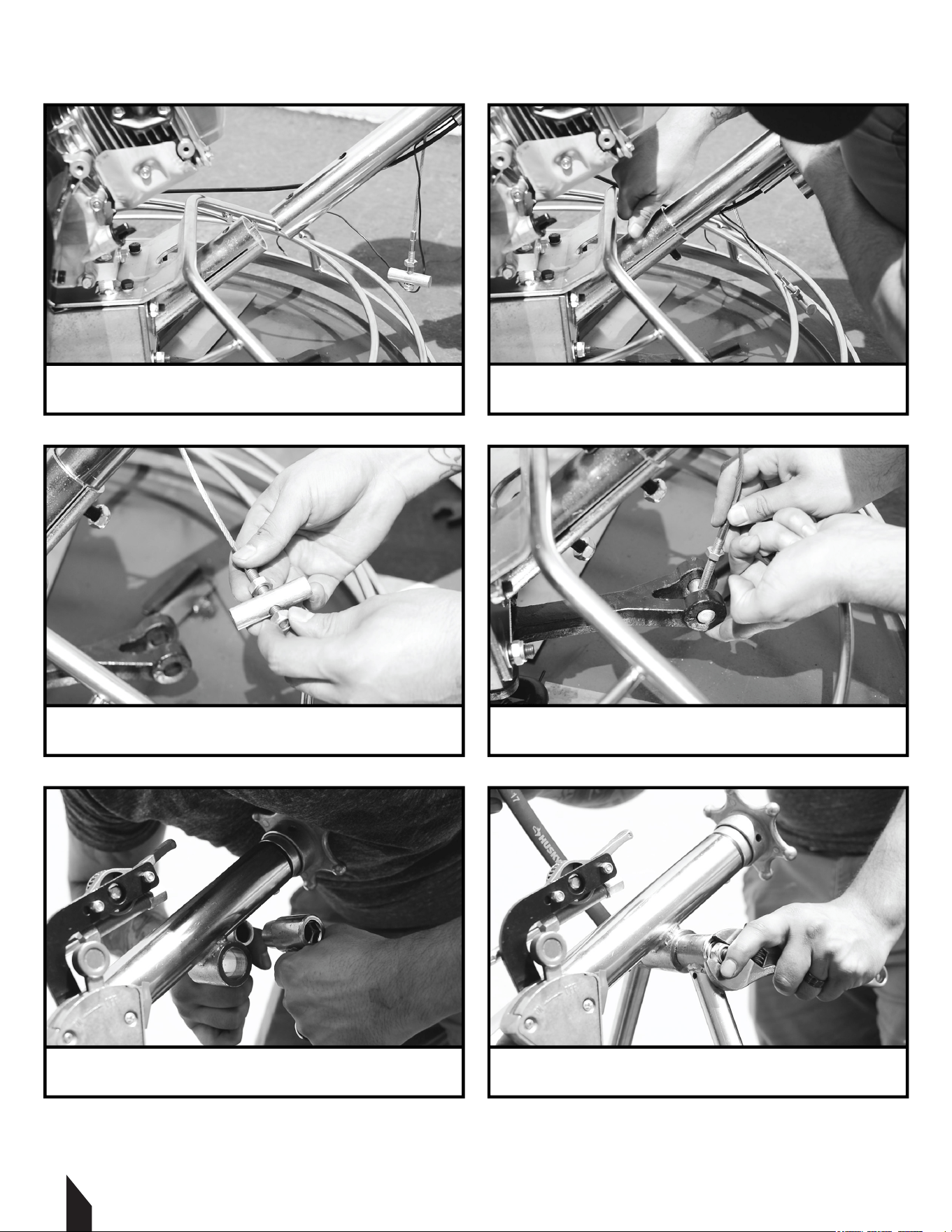
Insert the bolts and washers through the
holes in the handle bar - fasten with a nut.
4
Fit the screw through the pin and fasten the
nuts on the top and bottom to keep it in place.
6
Place the bolt through the base of the
handles and then fasten with a nut on the end.
1
Insert the end of the handle bar column into
the base of the trowel.
3
Unscrew the nut from the pin and insert the
pin through the base of the trowel.
5
Fit the handle bars around the eye towards
the top of the handle bar column.
10
4. QUICK ASSEMBLY GUIDE
77 X 58 mm 88 X 64 mm
389 cm3
6.4 U.S. qts (6.1 liters)
1.16 US qt (1.1 L) 1.16 US qt (1.1 L)
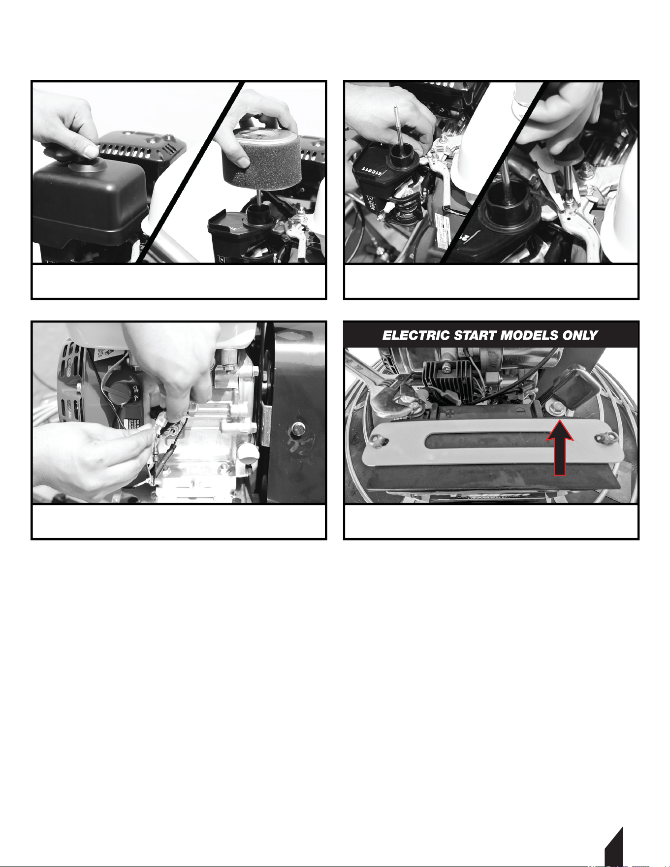
8
Feed the cable throughthe pivot nut and
through the swivel stop, then fasten the screw.
10
Fasten the positive (red) and negative
(black) engine leads to the battery.
12
Pull the housing back and slide the end of
the cable into the engine’s throttle terminal.*
7
To attach the throttle cable, remove the air
filter and the cover.
9
Bring the kill switch wire to the front of the
engine and connect it the the shut off switch.
11
Fit the top of the cable housing into the
slot and tighten the locknuts.
* Move the throttle control back and forth to make sure the cable is engaged.
11
4. QUICK START GUIDE CONTINUED
5. CONTROLS AND COMPONENTS
1 Standard Handle
Includes a "starwheel" for manually adjusting blade pitch.
5.2 Foldable Quick Pitch Handle
Employs a lever handle to quickly adjust blade pitch. Handle folds for storage.
5.3 Centrifugal Kill Switch
In the event the operator loses control of the trowel, this switch will shut-down the engine.
5.4 Throttle Control Lever
The throttle controls the speed of the engine. Move the hand lever towards the operator to
increase engine speed (high), away from the operator to decrease engine speed (low).

5.5 Bicycle Handlebars
The trowel’s wider handlebars allow for higher stability, balance, and maneuverability.
Replace handle grips if they become worn or damaged.
5.6 Engine
Tomahawk Power Trowels use Honda and Kohler engines and are backed by a 3-year
engine warranty for reliable service.
5.7 Blade Pitch Control
Adjust the trowel’s steel blades from 0-28 degrees to achieve a matte, light gloss, or
gleaming finish.
5.8 Guard Ring
NEVER put hands and feet inside the guard ring.
5.9 Trowel Arm
Provides attachment points for the blades. If the blades show uneven wear patterns or if
blades wear out faster than others, the trowel arm may need to be replaced.
5.10 Blades
This trowel is equipped with 4 combo hardened, steel blades designed for both float and
finish operations. These blades are interchangeable with most manufacturers.
5.11 V-Belt Cover
Remove this cover to gain access to the V-Belt. NEVER operate the trowel with this cover
removed.
5.12 Tee Handle
Loosen to fold handle.
5.2 Additional Components
5.2.1 Stabilizer Ring
The stabilizer ring reduces the vibrations from the trowel arm and keeps it balanced.
5.2.2 Float Pan
Designed to clip onto the combo blades, the float pan works to break down high spots,
bringing mortar to the surface and producing a uniform and level slab.
5.2.3 Auxiliary Liing Tube
Use this tube to li the trowel onto a slab. Tube is to be inserted into the socket located in
front of the gearbox. Available with select units.
12

13
6. ENGINE
6.1 Servicing
Tomahawk Power Trowels are powered by Honda and Kohler engines. The engine must be
checked for proper lubrication and filled with fuel prior to operation. Refer to the
manufacturers engine manual for instructions & details of operation and servicing. If a
problem should arise, or if you have any questions about your engine, consult an
authorized Honda or Kohler servicing dealer.
The Importance Of Maintenance
Good maintenance is essential for safe, economical and trouble-free operation. It will also
help reduce pollution.
To help you properly care for your engine, the following pages include a maintenance
schedule, routine inspection procedures, and simple maintenance procedures using basic
hand tools. Other service tasks that are more difficult, or require special tools, are best
handled by professionals and are normally performed by a Honda or Kohler technician or
other qualified mechanic.
The maintenance schedule applies to normal operating conditions. If you operate your
engine under severe conditions, such as sustained high-load or high-temperature
operation, or use in unusually wet or dusty conditions, consult your servicing dealer for
recommendations applicable to your individual needs and use.
Maintenance, replacement, or repair of the emission control devices and systems may
be performed by any engine repair establishment or individual, using parts that are
‘‘certified’’ to EPA standards.
6.2 Maintenance Safety
Some of the most important safety precautions follow. However, we cannot warn you of
every conceivable hazard that can arise in performing maintenance. Only you can decide
whether or not you should perform a given task.
WARNING:
Improper maintenance, or failure to correct a problem before operation, can cause a
malfunction in which you can be seriously hurt or killed. Always follow the inspection and
maintenance recommendations and schedules in this owner’s manual.
WARNING:
Failure to properly follow maintenance instructions and precautions can cause you to be
seriously hurt or killed. Always follow the procedures and precautions in this owner’s manual.
CAUTION:
NEVER attempt to li the trowel by yourself.
ALWAYS get assistance from another person to help li the trowel.

14
6.2 Maintenance Safety Continued
6.2.1 Fuel Filler Cap
Remove this cap to add unleaded gasoline to the fuel tank. Make sure the fuel filler cap is
tightened securely. DO NOT overfill.
6.2.2 Throttle Lever
The throttle lever is used to adjust engine RPM speed (lever advanced forward SLOW, lever
back toward operator FAST).
6.2.3 Engine ON/OFF Switch
ON position permits engine starting, OFF position stops engine operations.
6.2.4 Recoil Starter (Pull Rope)
Manual-starting method. Pull the starter grip until resistance is felt, then pull briskly and
smoothly.
6.2.5 Fuel Valve Level
OPEN to let fuel flow, CLOSE to stop the flow of fuel.
6.2.6 Choke Lever
Used in the starting of a cold engine or in cold weather conditions, the choke enriches the
fuel mixture.
6.2.7 Air Cleaner
The air cleaner prevents dirt and other debris from entering the fuel system. To access the
filter element, remove the wing-nut on top of the air filter canister.
NOTE:
Do not operate the engine without an air filter, with a damaged air filter, or a filter in need of replacement.
This will allow dirt to enter the engine and cause rapid engine wear.
6.2.8 Spark Plug
The spark plug provides a spark to the ignition system. Clean the spark plug once a week.
Set the spark plug gap to 0.6 - 0.7mm (0.028 - 0.031in).
6.2.9 Muffler
The muffler is used to reduce noise and emissions from the engine.
WARNING:
Engine components can generate extreme heat. To prevent burns, DO NOT touch these areas
while the engine is running or immediately aer operating. NEVER operate the engine with
the muffler removed.

15
6.2 Maintenance Safety Continued
6.2.10 Fuel Tank
The fuel tank holds unleaded gasoline. For more information, refer to the engine owner’s
manual.
7. PRE-INSPECTION
NEVER operate the power trowel in a confined area or enclosed structure that does not
provide ample free flow of air.
ALWAYS wear approved eyewear and hearing protection before operating the trowel.
NEVER place hands or feet inside the guard rings while the engine is running.
ALWAYS shut the engine down before performing any kind of maintenance on the trowel.
It is recommended that the trowel's kill switch be used to stop the engine aer every use.
Doing this will verify that the switch is working properly and presents no danger to the
operator.
7.1 Before Starting
7.1.1 Read the safety instructions at the beginning of this manual.
7.1.2 Clean the power trowel by removing dirt and dust, particularly in the engine cooling
air inlet, carburetor, and air cleaner.
7.1.3 Check the air filter for dirt and dust. If the air filter is dirty, replace it with a new one as
required.
7.1.4 Check the carburetor for external dirt and dust. Clean it with dry compressed air.
7.1.5 Check fastening nuts and bolts for tightness.
7.2 Engine Oil Check
7.2.1 To check the engine oil level, place the power trowel on a secure level ground with
the engine stopped.
7.2.2 Remove the filler dipstick from the engine oil filler hole (Figure 2) and wipe it clean.
7.2.3 Insert and remove the dipstick without screwing it into the filler neck. Check the oil
level shown on the dipstick.
7.2.4 If the oil level is low (Figure 3), fill to the edge of the oil filler hole with the
recommended with SAE10W-30 4 stroke oil. Maximum oil capacity is 400 cc.
NOTE:
Refer to Honda or Kohler Engine Manual for specific servicing instructions.
16
7.3 Fuel Check
Engine fuels are highly flammable and can be dangerous if mishandled. DO NOT smoke
while refueling. DO NOT attempt to refuel the trowel if the engine is hot or running.
7.3.1 Remove the gasoline cap that is located on
top of the fuel tank.
7.3.2 Visually inspect to see if fuel level is low. If fuel
is low, replenish with 89 Octane gasoline.
7.3.3 When refueling, be sure to use a strainer for
filtration. DO NOT top-off the fuel. Wipe up any
spilled fuel.
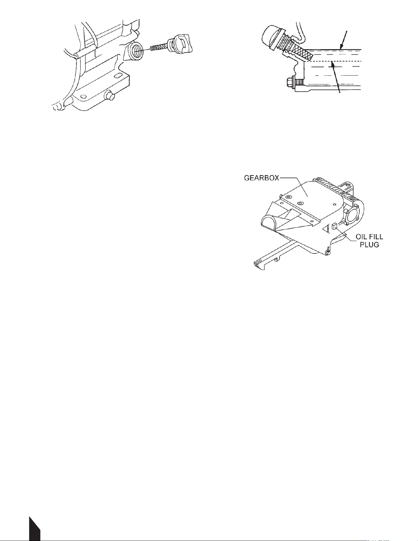
7.4 Gearbox Oil
7.4.1 Determine if the gearbox oil is low by
removing the oil plug located on the side of the
gearbox. This plug will be marked by the "check" decal. See Figure 4. The correct level of the
lubrication oil should be to the bottom of the fill plug.
7.4.2 If lubrication oil begins to seep out as the drain plug is being removed, then it can be
assumed that the gearbox has a sufficient amount of oil.
7.4.3 If lubrication oil does not seep out as the drain plug is being removed, fill with type ISO
680 gearbox lubricant oil until the oil filler hole overflows.
7.5 V-Belt Check
A worn or damaged V-belt can adversely affect the performance of your power trowel. If a
V-belt is defective or worn out, simply replace the V-belt as outlined in the maintenance
section of this manual.
7.6 Blade Check
Before starting, check for worn or damaged blades. If one blade is worn out while the others
look new, this could be because of a blade pitch problem. Refer to the maintenance section
of this manual for instructions on the blade pitch adjustment procedure. Replace any worn
out blades.
FIGURE 2
FIGURE 3
FIGURE 4

17
7.7 SAFETY KILL SWITCHES
This power trowel has been equipped with a safety kill switch. Safety kill switches should
be tested every time the engine is started.
NOTE
NEVER! disable or disconnect the kill switch. It is provided for operator safety. Injury may result if it is
disabled, disconnected, or improperly maintained.
7.8 HANDLE PRESS KILL SWITCH
Located on the main handle tube is a red switch (Figure 5). The
switching mechanism of this switch should operate freely and
should always be kept in this condition. With the switch in the
OFF position, the engine should not start or run. The purpose of
this switch is to stop the engine in a runaway situation, (i.e.-the
operator releasing the handle during operation).
DO NOT let the machine sit unused with the engine at high speed for an extended period of
time. It will cause premature belt wear or may destroy the belt. ALWAYS set the engine
speed to idle when the hand clutch is disengaged.
8. INITIAL START-UP
Liing the Trowel Onto a Slab
8.1 Auxiliary Liing Tube
Remove the auxiliary liing tube located on top of the main handle. Insert the tube into the
socket located on the opposite side of the gearbox from the handle. Make sure that the
hole in the tube engages with the pin in the socket. With one person liing from the main
handle, and another liing from the auxiliary liing tube, pick up the machine to move
onto a slab.
8.2 Liing Bale
The li bale is optional on new trowels. It provides an optimal li point for moving the
trowel. Li bales or forkli can be used to li a trowel up onto a building with a crane.
Using a crane to move a machine with a li bale is highly recommended, and is perfectly
safe for the machine. Extra care should be taken when liing the machine off the ground,
though. Serious damage to the machine or personal injury could be caused by dropping a
trowel.
WARNING:
The trowel must be stabilized by the person carrying the operator’s handle. If it is not stabilized
properly the handle may swing around and flip the trowel, thus causing damage to the trowel
and bodily injury.
FIGURE 5
1718
8.2 Liing Bale Continued
This section is intended to assist the operator with the initial start-up of the walk-behind
trowel. It is extremely important that this section be read carefully before attempting to use
the trowel in the field.
DO NOT use your trowel until this section is thoroughly understood
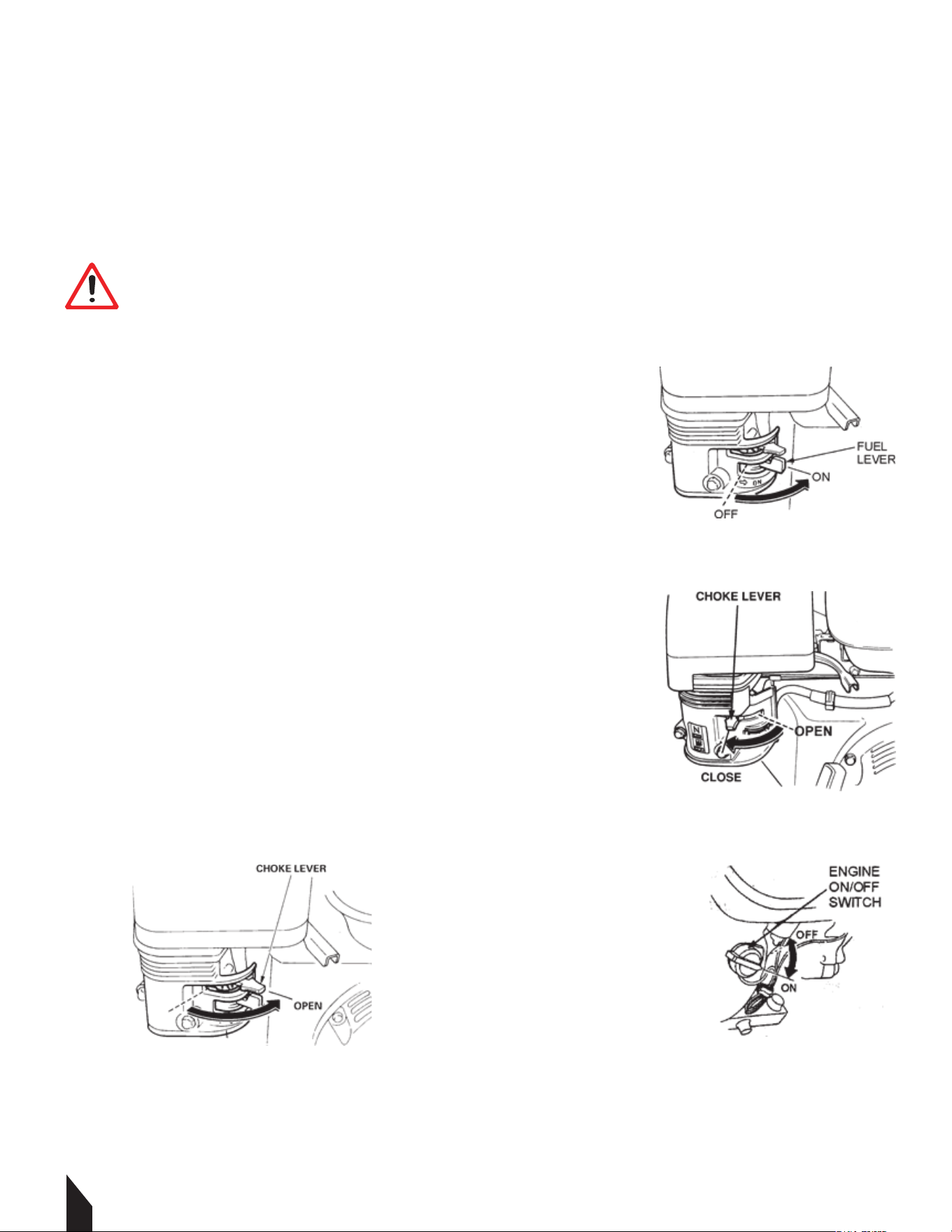
9. STARTING THE ENGINE
9.1 Place the engine fuel valve lever (Figure 6) to the "ON"
position.
9.2 Place the trowel's throttle lever (Figure 1) to the "IDLE"
position.
9.3 Place the choke lever (Figure 7) in the "CLOSED " position
if starting a cold engine.
9.4 Place the choke lever (Figure 8) in the "OPEN" position if
starting a warm engine or the temperature is warm.
9.5 Place the engine ON/OFF switch (Figure 9) in the "ON "
position.
WARNING:
DO NOT attempt to operate the trowel until the Safety, General Information, and Inspection
sections of this manual have been read and thoroughly understood. Depending on the engine
manufacturer, operating steps may vary. See engine manufacturer's operating manual.
FIGURE 6
FIGURE 7
FIGURE 8 FIGURE 9
19
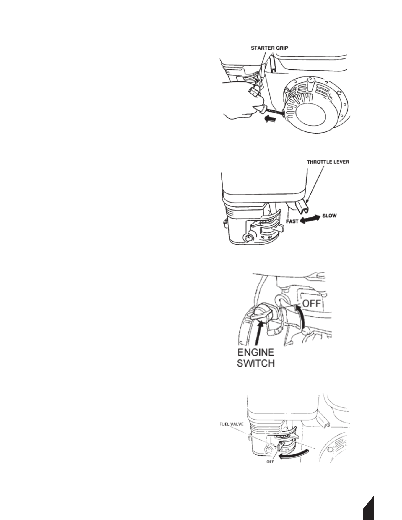
9. STARTING THE ENGINE CONTINUED
9.6 Grasp the starter grip (Figure 10) and
slowly pull it out. The resistance becomes
the hardest at a certain position,
corresponding to the compression point.
Pull the starter grip briskly and smoothly for
starting.
9.7 If the engine has started, slowly return
the choke lever (Figure 7) to the OPEN
position. If the engine has not started
repeat steps 1 through 6.
9.8 Before the trowel is placed into
operation, run the engine for several
minutes. Check for fuel leaks, and noises
that would associate with a loose V-belt
cover or component.
9.9 To begin troweling, move the throttle
lever (Figure 11) toward the "FAST"
position.
10. STOPPING THE ENGINE
10.1 Move the throttle lever to the IDLE or
SLOW position (Figure 11) and run the
engine for three minutes at low speed.
10.2 Aer the engine cools, turn the engine
start/stop switch to the “OFF” position
(Figure 12).
10.3 Close the fuel shut- off valve (Figure
13) by moving the fuel valve lever to the OFF
position.
FIGURE 10
FIGURE 11
FIGURE 13
FIGURE 12

1720

21
17
22
11. OPERATION
The following steps are intended as a basic guide to machine operation, and are not to be
considered a complete guide to concrete finishing. Read the “Training” section of this
manual for more information.
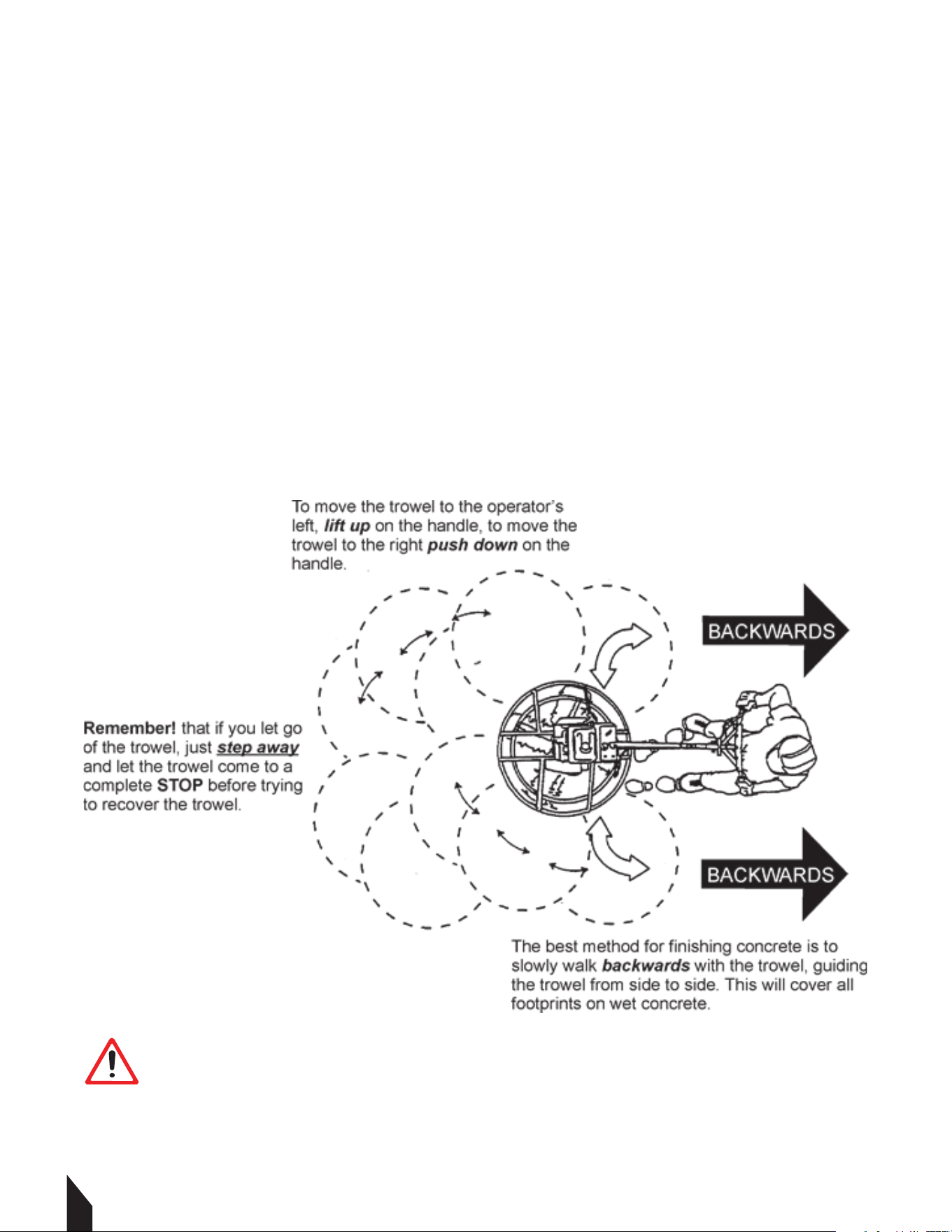
11.1 Maneuvering the Trowel
11.1.1 Get into the operator’s position behind the handle. With a secure foothold and a
rm grasp on the handles slowly increase the engine speed until the desired blade speed is
obtained.
11.1.2 To maneuver the trowel, gently lift up on or press down on the main trowel handle.
To move the machine to the operator’s left, lift up on the handle, to move the machine to
the right, push down on the handle.
11.1.3 Adjust the blade pitch on the Standard handle, by turn the Pitch Adjust Wheel
clockwise or counter- clockwise.
WARNING:
NEVER place your feet or hands inside the guard rings while starting or operating this
equipment.
ALWAYS keep clear of rotating or moving parts while operating this equipment.
FIGURE 14

23
FIGURE 15
12. ACCESSORY OPTIONS
12.1 Blades
NOTE
Blades should be changed when they fail to finish concrete in a satisfactory manner.
Blades are a vital part of finishing concrete. This Tomahawk Trowel has been designed to
finish concrete and is built to stringent quality standards out of the finest trowel steel. If you
need replacement blades, consult your parts list in this manual for part numbers and order
them from the Tomahawk Website
FIGURE 4 your Tomahawk parts dealer.
12.2 Combo Blades
This trowel was equipped with combination
FLOAT/FINISH (Figure 15) blades as original
equipment. These blades have been designed for
optimum performance in both the floating and
finishing operations. These blades are versatile and
should take care of most troweling needs.
12.3 Finish Blades (Optional)
These blades have been specifically designed for finish operations with this trowel. They will
provide a premium surface finishing capability from your trowel. They should only be used
aer the concrete has set to the point where the trowel does not sink into the concrete when
placed on it.
12.4 Clip-On Float Blades (Optional)
These blades will clip (Figure 16) on to an existing
installed blade, allowing your finisher to float on
“wet” concrete so that the troweling operation can
begin as early as possible. They are easily removable,
so that aer the floating operation, when the
concrete is sufficiently cured, they can be removed to
expose the finish blades for continued troweling.
12.5 Float Discs (Optional)
These round discs attach to the spiders and allow the machine to “float” on “wet” concrete.
The disc design allows early floating and easy movement from wet to dry areas. They are
also very effective in embedding large aggregates and surface hardeners.
FIGURE 16

24
13. MAINTENANCE
13.1 Maintenance Schedule
Daily (8-10 Hours)
1. Check the oil level in the engine crankcase and gear box, fill as necessary.
2. Check V-belt.
Weekly (50-60 Hours)
1. Relube arms, thrust collar and clutch
2. Replace blades if necessary.
3. Check and clean or replace the engine air filter as necessary.
4. Replace engine oil and filter as necessary, see engine manual.
Monthly (200-300 Hours)
1. Remove, clean, reinstall and relube the arms and thrust collar. Adjust the blade arms.
Yearly (2000-2500 Hours)
1. Check and replace if necessary the arm bushings, thrust collar bushings and sha seals.
2. Check pitch control cables for wear.
3. Adjust blade speed.
13.2 Trowel Arm Adjustment
Use the following procedure to check and adjust trowel arms, and check for worn or
damaged components when it becomes apparent that the trowel is finishing poorly or in
need of routine maintenance. Look for the following indications. Trowel arm alignment,
worn spider bushings or bent trowel arms may the cause.
■ Are blades wearing unevenly? Is one blade completely worn out while the others look new?
■ Does the machine have a perceptible rolling or bouncing motion when in use?
■ Look at the machine while it is running; do the guard rings “rock up and down” relative to the ground?
13.2.1 Place the trowel in a FLAT, LEVEL area.
A level, clean area to test the trowel prior to and aer is essential. Any unlevel spots in the
floor or debris under the trowel blades will give an incorrect perception of adjustment.
Ideally, a 5 x 5 Ft. (1.5 x 1.5 Meter) three-quarter inch (19 mm) thick FLAT steel plate should be
used for testing.
13.2.2 Pitch the blades as flat as possible. The adjustment bolts should all barely make
contact with the lower wear plate on the spiderbox. If one is not making contact, adjustment
will be necessary. (Figure 17
FIGURE 4).
25
13.2 Trowel Arm Adjustment Continued
Figure 17 illustrates, "incorrect alignment", worn spider bushings or bent trowel arms. Check
that the adjustment bolt is barely touching (0.10" max. clearance) lower wear plate. All
alignment bolts should be spaced the same distance from the lower wear plate.
1 Adjustment Bolt
2 Lower Wear Plate
3 Surface
4 "Dished" Effect on Finished Concrete
13.3 Trowel Blade Removal
13.3.1 Remove the trowel blades from the trowel arm by
removing the two hex head bolts from the trowel arm. Set
blades aside.
13.3.2 Wire brush any build-up of concrete from all six
sides of the trowel arm. Repeat this for the remaining
three arms.
13.4 Re-Assembly
13.4.1 Clean and examine the upper/lower wear plates
and thrust the collar.
13.4.2 Examine the entire spider assembly. Wire brush any
concrete or rust build-up. If any spider components are
found to be damaged or misshaped, replace it.
13.4.3 Reinstall bronze bushing on the trowel arms.
13.4.4 Repeat above steps for each trowel arm.
13.4.5 Make sure that the spring tensioner is in the correct position to exert tension on the
trowel arm.
13.4.6 With the bronze bushing already installed, insert all the trowel arms with levers into
the spider plate.
13.4.7 Use care to align the grease hole on the bronze bushing with the grease hole fitting on
the spider plate.
13.4.8 Lock the trowel arms in place by tightening the hex head bolt with zerk grease fitting
and jam nut.
13.4.9 Re-install the blades onto the trowel arms.
13.4.10 Install the stabilizer ring onto the spider assembly.
WARNING:
Disconnect the spark plug wire from the spark plug and secure away from the engine before
performing maintenance or adjustments on the machine.
FIGURE 17
FIGURE 18

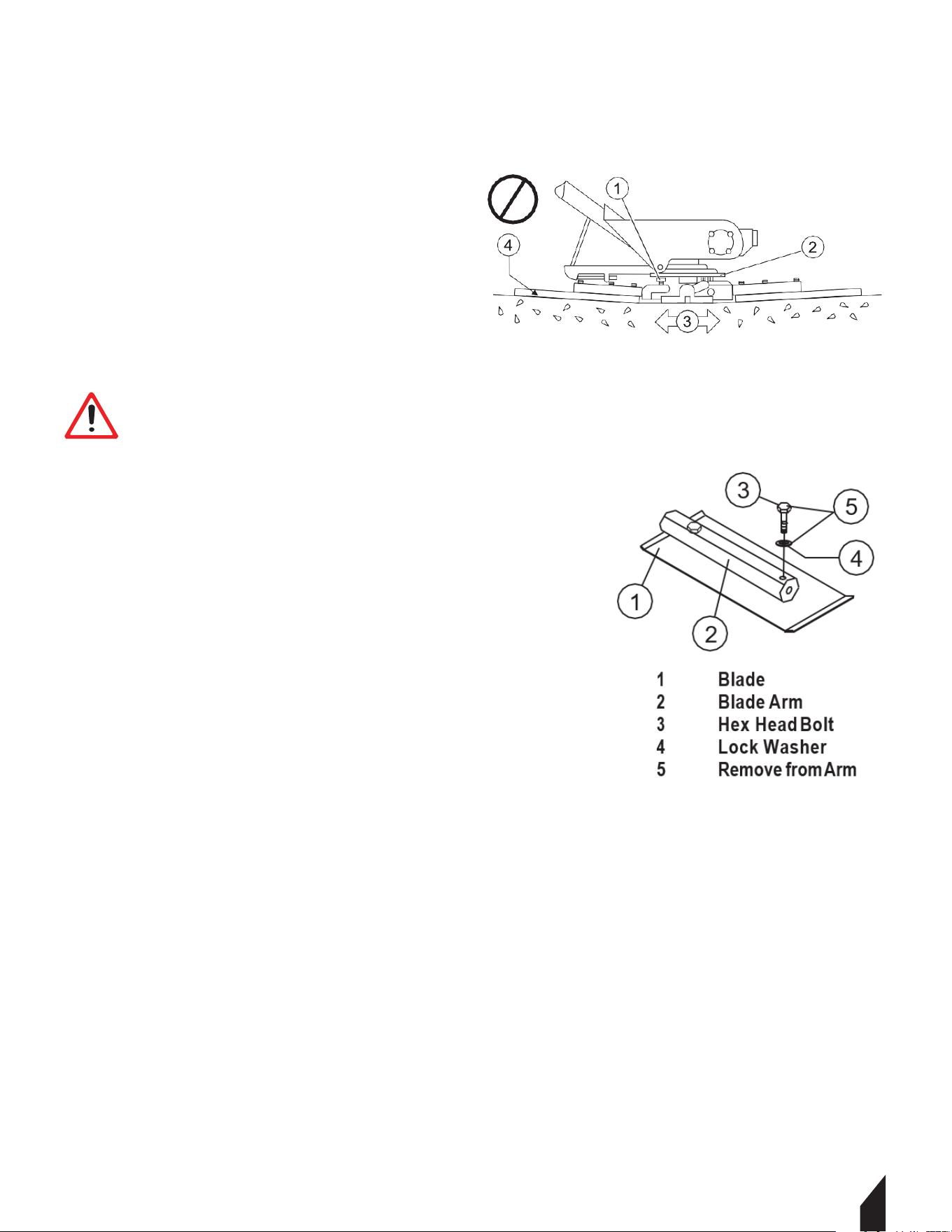
13.5 Changing Blades Only
We recommend that all of the blades are changed at the same time. The trowel may wobble
or bounce if not.
13.5.1 Place the machine on a flat, level surface. Adjust the blade pitch control to make the
blades as flat as possible.
NOTE
Pay attention to the blade orientation on the trowel arm.
13.5.2 Remove the two bolts and lock the washers that secure the blade to the trowel arm.
13.5.3 Remove the blade.
13.5.4 Using a wire brush, scrape all concrete particles and forgein debris from the trowel
arm.
13.5.5 Install the new trowel blade onto the trowel arm. Make sure the blade is installed
correctly, maintaining the proper orientation for direction of rotation.
13.5.6 Reinstall the two bolts and lock washers that secure the blade to the trowel arm.
Tighten the bolts securely.
13.5.7 Repeat steps for all remaining blades.
13.6 Installing Pans onto Finisher Blades
13.6.1 Li the trowel just enough to slide the pan under the blades. With the blades adjacent
to the Z-clips, lower the finisher onto the pan.
13.6.2 Rotate the blades into position under the Z-clips. Ensure that the blades are rotated
in the direction of travel when the machine is in operation. Or, use the engine to rotate the
blades into position.
13.6.3 Attach the blade tie-downs to the far side of the Z-clip brackets with tie-down knobs.
13.6.4 Before the machine is put back into operation, check to make sure that the blade
edges are secured under the Z-clips.
13.6.5 Before the machine is put back into operation, check to make sure that the tie-downs
are secured firmly over the edges of the blade.
WARNING:
Liing/Crush Hazard.
Do not li the trowel with the pans attached.
ALWAYS install the pans on the work area or an area that is next to/level with the work area.
DO NOT li the trowel when the pans are attached.
26
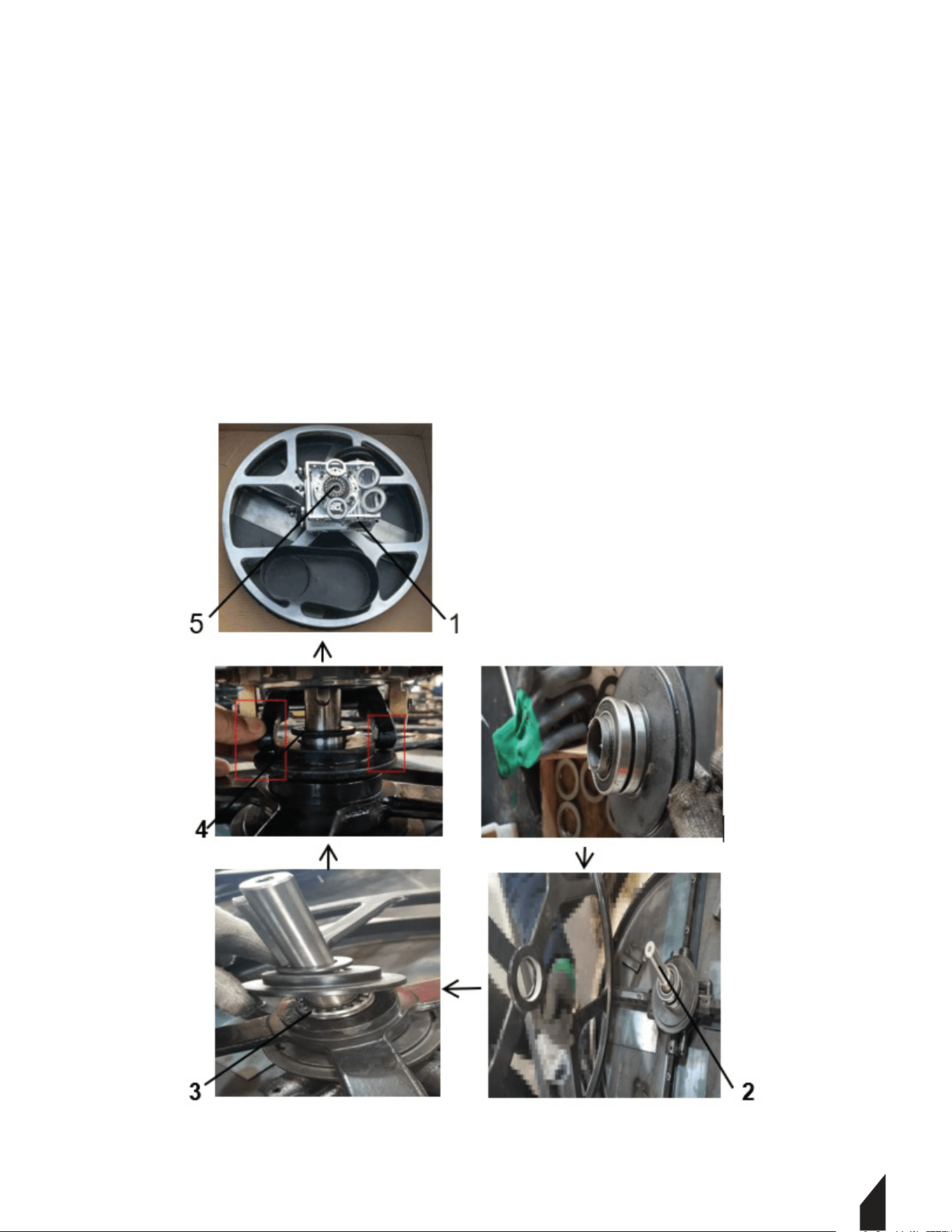
13.7 Spider Box Removal
13.7.1 Once it is determined that an adjustment is required, remove the spider assembly
from the gearbox sha as follows:
13.7.2 Remove the zerk fitting and allen head screw designated by the letter “S”.
13.7.3 On the opposite side of the spider block, there is another zerk fitting and allen head
screw. Remove both of these components.
13.7.4 Li the upper trowel assembly off of the spider assembly.
NOTE
A slight tap with a rubber mallet may be necessary to dislodge the spider from the main sha of the gearbox.
27

1728
14. TRAINING CHECKLIST
This checklist lists the requirements for proper machine maintenance and operation. Please
feel free to detach it and make copies. Use this checklist whenever a new operator is to be
trained.
NO. DESCRIPTION COMPLETED DATE
1 Read Operator’s Manual completely
2
Understand machine layout, location of components,
check engine and gearbox fluid level
3 Understand fuel system, refueling procedure
4 Understand how to operate machine
5 Understand safety controls
6 Understand emergency stop procedures
7 Start Up the machine
8 Properly Maneuver the machine
9 Understand blade bitch adjusment
10 Understand proper prope
r finishing techniques
11 Understand how to shutdown of machine
12 Understand how to safely lift the machine
13 Understand proper machine transport and storage
TRAINING CHECKLIST
Operator Trainee
Comments:

29
TPT36H, TPT46H-270, TPT46H-390
POWER TROWEL
Parts Manual
Page 22 of 33
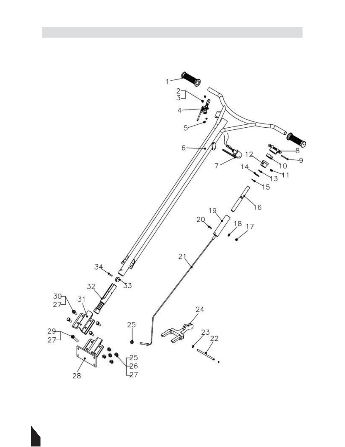
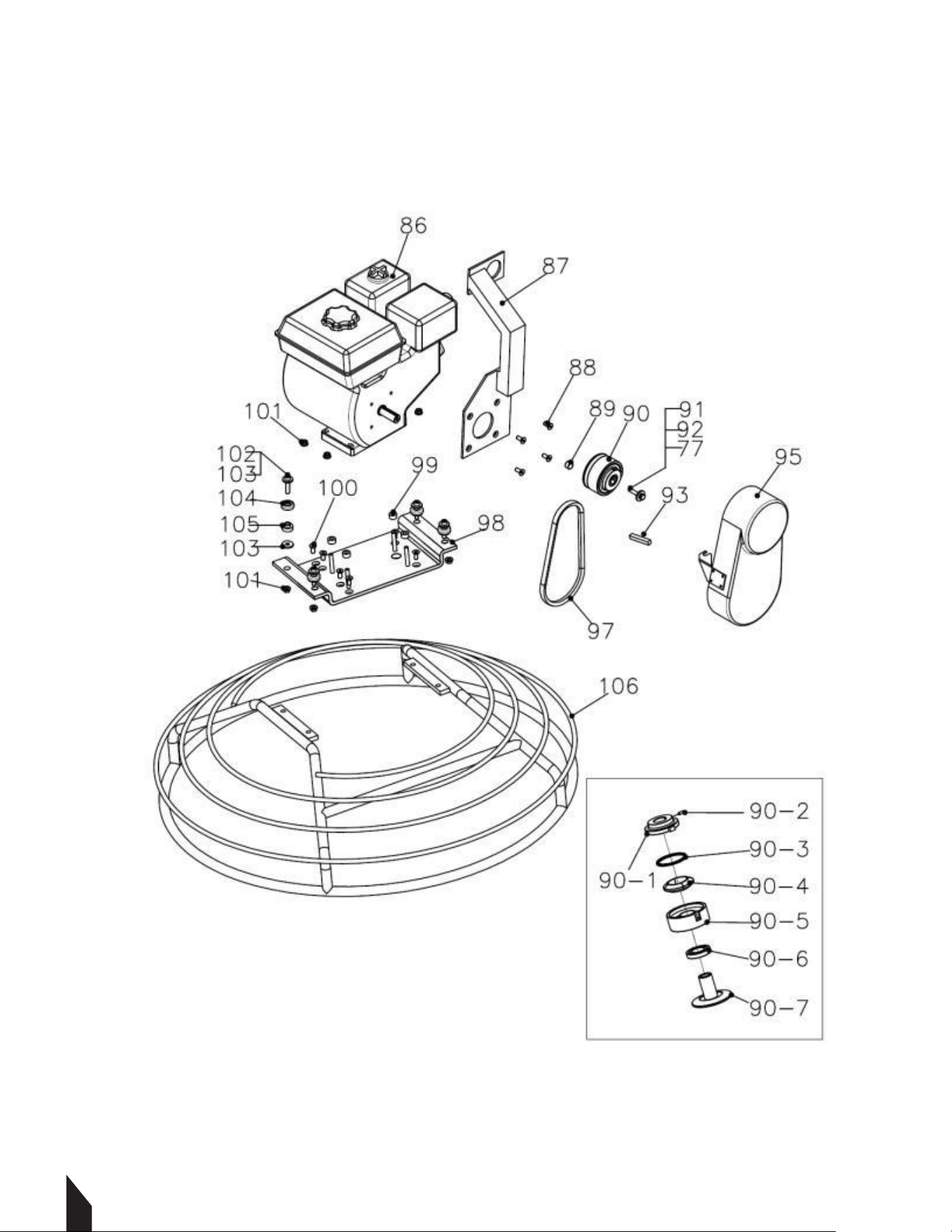
Parts Diagram
Handle
30

Page 23 of 33
REF Parts No. Description Q’TY Dimension
1 RG-003 Plastic Cover 2
2 QSC-M4*8 Screw 2 M4x8
3 QWS-PM4 Plate Washer 2 M4
4 TSA-01 Throttle Assy. 1
5 QNT-NM4 Nylock Nut 2 M4
6 W436F-001 Handle WA 1
7 PAS-02 Stop Switch(release bar Type) 1
8 436F-01-001 Adjust Knob 1
9 QSP-5X50 Spring Pin 1 5x50
10 QBR-51104 Bearing 1
11 QBL-M6X10 Bolt 1 M6x10
12 436F-01-004 Aluminium Guide 1
13 QWS-WM19 Wave Washer 1 M19
14 QWS-PM19 Plate Washer 1 M19
15 QSR-S18 Snap Ring 1 S18
16 436F-01-002 Adjust Screw Pipe 1
17 QBL-M6X8 Bolt 1 M6x8
18 QWS-PM6 Spring Washer 1 M6
19 436F-01-003 Screw Guide 1
20 QSP-5X30 Spring Pin 1 5x30
21 436F-01-007 WT Steel Wire 1
22 436F-02-004 Yoke Arm Pin 1
23 QSR-S10 Snap Ring 2 S10
24 436F-02-003B Yoke Arm 1
25 QNT-NM10 Nylock Nut 10 M10
26 QWS-SM10 Spring Washer 14 M10
27 QWS-PM10 Plate Washer 18 M10
28 436F-02-001 Handle Support Base 1
29 QBL-M10X70 Bolt 1 M10x70
30 QBL-M10X35 Bolt 4 M10x35
31 436F-02-002 Upper Bracket 1
32 436F-01-005 Alumium yoke 1
33 436A-01-010 Wheel 1
34 QSP-3X30 Spring Pin 1 3x30
Page 28 of 33
Safety Ring
31
Page 24 of 33
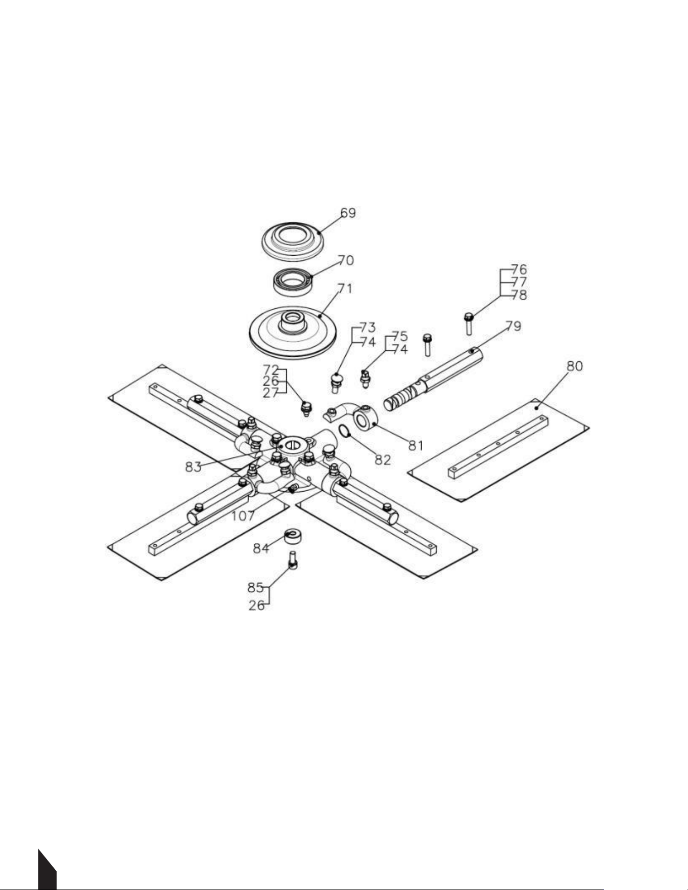
Blade
Page 29 of 33
REF
Parts No.
Description
Q’TY
Dimension
77
QWS-SM8
Spring Washer
M8
86
GX160
Engine GX-160
1
87
W436F-005
Hook Lift
1
(Option)
88
QBL-SHM8X20
Socket Head Cap Bolt
4
(Option)
89
436F-04-013
Clutch Busing
1
90
CA-01
Clutch
1
90-1
CA-01-004
Face Plate
1
90-2
QBL-AM8x16
Set Screw
2
M8x16
90-3
CA-01-005
Clutch Spring
1
90-4
CA-01-003
Shoe Weight
1
90-5
CA-01-002
Clutch Drum
1
90-6
QBR-6006
Bearing
1
6006
90-7
CA-01-001
Clutch Shaft
1
91
QBL-M8X35
Bolt
1
92
QWS-SPM8
Special Plate Washer
1
93
QKY-5x5x50
Key
1
95
436F-04-006
Belt Cover
1
97
QBT-A26
V-Belt
1
A26
98
W436F-002
Engine Mount Plate
99
436F-04-107
Engine Mount Bushing
100
QBL-FHM8X20
Flat Head Cap Bolt
4
101
QNT-M8
Nut
8
M8
102
QBL-LM8X40
Socket Head Bolt
4
M8X40
103
QWS-PM8
Plate Washer
8
M8
104
436F-04-004
Cup
4
105
436F-04-003
Rubber
4
106
W436F-004B
Safety Ring
1
17
32

Page 25 of 33
REF Parts No. Description Q’TY Dimension
26 QWS-SM10 Spring Washer 5 M10
27 QWS-PM10 Plate Washer 4 M10
69 436F-02-005B Press Plate Cap 1
70 QBR-6009 Bearing 1 6009
71 436F-02-006B Press Plate Cap 1
72 QBL-M10X20 Bolt 4 M10x20
73 QBL-BBM10X35 Round Head Bolt 4 M10x35
74 QNT-TM10 Thin Nut 8 M10
75 QBL-SHM10X30 Square Head Bolt 4
76 QBL-7/16X11/2 Bolt 8 7/16*3/2L
77 QWS-SM8 Spring Washer 8 M8
78 QWS-PM8 Plate Washer 8 M8
79 436F-02-009B Blade Arm 4
80 436F-02-014 Blade Assembly 4
81 436F-02-008 Tilt Arm 4
82 QOR-S22 O-ring 4 22x1.5t
83 436F-02-007B Spider 1
84 436F-02-010 Spider Bushing 1
85 QBL-LM10X30 Socket Bolt 1 M10x30
33
Page 26 of 33
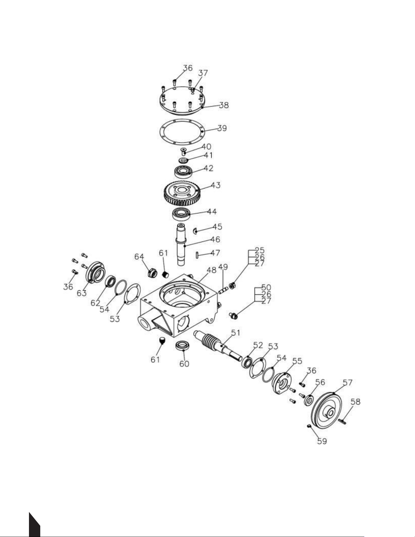
Gear Box
34

Page 27 of 33
REF Parts No. Description Q’TY Dimension
436F-03 Gear Box Assembly 1
25 QNT-NM10 Nylock Nut 4 M10
26 QWS-SM10 Spring Washer 5 M10
27 QWS-PM10 Plate Washer 5 M10
36 QBL-M6X16 Bolt 16 M6x16L
37 QRV-M8 Release Valve 1
38 436F-03-004 Big Cover 1
39 436F-03-005 Gasket of Big Cover 1
40 QBL-FHM10x25 Flat Socket Head Bolt 1 M10x25
41 QWS-SSM10 Washer 1 M10
42 QBR-30305 Bearing 1 30305
43 436F-03-008 Worm Gear 1
44 QBR-6206 Bearing 1 6206
45 QKY-W6X10X25 Wood Key 1 6x10x25
46 436F-02-012 Main Shaft 1
47 QKY-6X25 Key 1 6x25
48 436F-03-001 Shell 1
49 QBL-STM10x40 Stud Bolt 4 M10x40
50 QBL-M10X16 Bolt 1 M10x16
51 436F-03-007 Worm Shaft 1
52 QBR-32004 Bearing 1 32004
53 436F-03-006 Gasket of Side Cover 2
54 QOR-P55 O-Ring 2 55x3.5t
55 436F-03-003 Output Side Cover 1
56 QOS-20X40X8 Oil Seal 1 20x40x8t
57 436F-04-005 Pulley 1
58 QKY-5X35 Key 1 5x35
59 QBL-M8X10 Bolt 1 M8x10
60 QOS-27X47X10 Oil Seal 1 27x47x10t
61 436A-03-008WT Oil Drain 2
62 QBR-6004 Bearing 1 6004
63 436F-03-002 Side Cover 1
64 QOCW-M27x1.5 Oil Check Windows 1 M27x1.5
35
Page 23 of 33
REF
Parts No.
Description
Q’TY
Dimension
1
RG-003
Plastic Cover
2
2
QSC-M4*8
Screw
2
M4x8
3
QWS-PM4
Plate Washer
2
M4
4
TSA-01
Throttle Assy.
1
5
QNT-NM4
Nylock Nut
2
M4
6
W436F-001
Handle WA
1
7
PAS-02
Stop Switch(release bar Type)
1
8
436F-01-001
Adjust Knob
1
9
QSP-5X50
Spring Pin
1
5x50
10
QBR-51104
Bearing
1
11
QBL-M6X10
Bolt
1
M6x10
12
436F-01-004
Aluminium Guide
1
13
QWS-WM19
Wave Washer
1
M19
14
QWS-PM19
Plate Washer
1
M19
15
QSR-S18
Snap Ring
1
S18
16
436F-01-002
Adjust Screw Pipe
1
17
QBL-M6X8
Bolt
1
M6x8
18
QWS-PM6
Spring Washer
1
M6
19
436F-01-003
Screw Guide
1
20
QSP-5X30
Spring Pin
1
5x30
21
436F-01-007 WT
Steel Wire
1
22
436F-02-004
Yoke Arm Pin
1
23
QSR-S10
Snap Ring
2
S10
24
436F-02-003B
Yoke Arm
1
25
QNT-NM10
Nylock Nut
10
M10
26
QWS-SM10
Spring Washer
14
M10
27
QWS-PM10
Plate Washer
18
M10
28
436F-02-001
Handle Support Base
1
29
QBL-M10X70
Bolt
1
M10x70
30
QBL-M10X35
Bolt
4
M10x35
31
436F-02-002
Upper Bracket
1
32
436F-01-005
Alumium yoke
1
33
436A-01-010
Wheel
1
34
QSP-3X30
Spring Pin
1
3x30
Page 28 of 33
Safety Ring
36

Page 24 of 33
Blade
Page 29 of 33
REF Parts No. Description Q’TY Dimension
77 QWS-SM8 Spring Washer M8
86 GX160 Engine GX-160 1
87 W436F-005 Hook Lift 1 (Option)
88 QBL-SHM8X20 Socket Head Cap Bolt 4 (Option)
89 436F-04-013 Clutch Busing 1
90 CA-01 Clutch 1
90-1 CA-01-004 Face Plate 1
90-2 QBL-AM8x16 Set Screw 2 M8x16
90-3 CA-01-005 Clutch Spring 1
90-4 CA-01-003 Shoe Weight 1
90-5 CA-01-002 Clutch Drum 1
90-6 QBR-6006 Bearing 1 6006
90-7 CA-01-001 Clutch Shaft 1
91 QBL-M8X35 Bolt 1
92 QWS-SPM8 Special Plate Washer 1
93 QKY-5x5x50 Key 1
95 436F-04-006 Belt Cover 1
97 QBT-A26 V-Belt 1 A26
98 W436F-002 Engine Mount Plate
99 436F-04-107 Engine Mount Bushing
100 QBL-FHM8X20 Flat Head Cap Bolt 4
101 QNT-M8 Nut 8 M8
102 QBL-LM8X40 Socket Head Bolt 4 M8X40
103 QWS-PM8 Plate Washer 8 M8
104 436F-04-004 Cup 4
105 436F-04-003 Rubber 4
106 W436F-004B Safety Ring 1
37

26
Item #: TVSA-H
4’-6’-8’-10’-12’-14’
POWER SCREEDS
www.tomahawk-power.com
FINISH 4X FASTER
Master your next concrete job with power screeds from TOMAHAWK!
Achieve incredible finishes 4x faster than traditional methods to
increase crew efficiency and jobsite profit! Choose magnesium or
aluminum screed boards from 4 to 14 long.
Page 25 of 33
REF
Parts No.
Description
Q’TY
Dimension
26
QWS-SM10
Spring Washer
5
M10
27
QWS-PM10
Plate Washer
4
M10
69
436F-02-005B
Press Plate Cap
1
70
QBR-6009
Bearing
1
6009
71
436F-02-006B
Press Plate Cap
1
72
QBL-M10X20
Bolt
4
M10x20
73
QBL-BBM10X35
Round Head Bolt
4
M10x35
74
QNT-TM10
Thin Nut
8
M10
75
QBL-SHM10X30
Square Head Bolt
4
76
QBL-7/16X11/2
Bolt
8
7/16*3/2L
77
QWS-SM8
Spring Washer
8
M8
78
QWS-PM8
Plate Washer
8
M8
79
436F-02-009B
Blade Arm
4
80
436F-02-014
Blade Assembly
4
81
436F-02-008
Tilt Arm
4
82
QOR-S22
O-ring
4
22x1.5t
83
436F-02-007B
Spider
1
84
436F-02-010
Spider Bushing
1
85
QBL-LM10X30
Socket Bolt
1
M10x30

Page 26 of 33
Gear Box
27
24
NEVER PUMP
NEVER LOSE PRESSURE
Lose the manual pump and gain the power to spray 15,000 ² in 10 minutes
or less while maintaining constant, adjustable pressure from 50-435 PSI with
your ideal concrete sealant, cure, top cast, form release, and more!
Item #: TCS6.5
6.5 GAL MOTORIZED
CONCRETE SPRAYER
www.tomahawk-power.com
Page 27 of 33
REF
Parts No.
Description
Q’TY
Dimension
436F-03
Gear Box Assembly
1
25
QNT-NM10
Nylock Nut
4
M10
26
QWS-SM10
Spring Washer
5
M10
27
QWS-PM10
Plate Washer
5
M10
36
QBL-M6X16
Bolt
16
M6x16L
37
QRV-M8
Release Valve
1
38
436F-03-004
Big Cover
1
39
436F-03-005
Gasket of Big Cover
1
40
QBL-FHM10x25
Flat Socket Head Bolt
1
M10x25
41
QWS-SSM10
Washer
1
M10
42
QBR-30305
Bearing
1
30305
43
436F-03-008
Worm Gear
1
44
QBR-6206
Bearing
1
6206
45
QKY-W6X10X25
Wood Key
1
6x10x25
46
436F-02-012
Main Shaft
1
47
QKY-6X25
Key
1
6x25
48
436F-03-001
Shell
1
49
QBL-STM10x40
Stud Bolt
4
M10x40
50
QBL-M10X16
Bolt
1
M10x16
51
436F-03-007
Worm Shaft
1
52
QBR-32004
Bearing
1
32004
53
436F-03-006
Gasket of Side Cover
2
54
QOR-P55
O-Ring
2
55x3.5t
55
436F-03-003
Output Side Cover
1
56
QOS-20X40X8
Oil Seal
1
20x40x8t
57
436F-04-005
Pulley
1
58
QKY-5X35
Key
1
5x35
59
QBL-M8X10
Bolt
1
M8x10
60
QOS-27X47X10
Oil Seal
1
27x47x10t
61
436A-03-008WT
Oil Drain
2
62
QBR-6004
Bearing
1
6004
63
436F-03-002
Side Cover
1
64
QOCW-M27x1.5
Oil Check Windows
1
M27x1.5
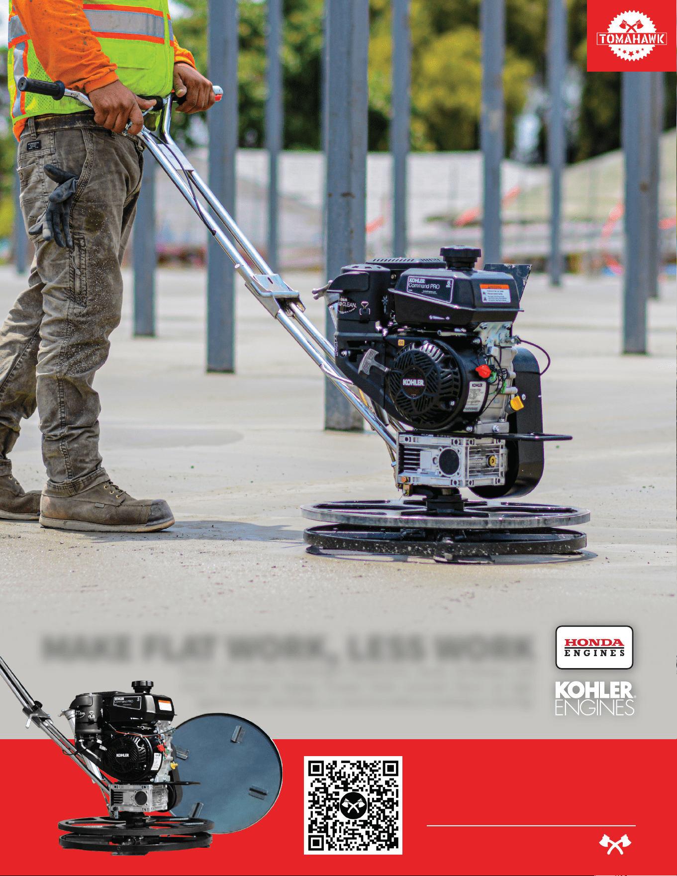
Item #: JXPT24K
24” - 36” - 46”
POWER TROWELS
www.tomahawk-power.com
MAKE FLAT WORK, LESS WORK
Perfect for concrete finishing of basements, decks, driveways, and
more, Tomahawk Edging Trowels finish concrete floors up tight
against walls, doorways, or columns without marking or marring!

24
WORK SMARTER
NOT HARDER
Powered by reliable Honda engines, TOMAHAWK Green Concrete Saws
ensure straight cuts up to 1-3/16” deep, perfect for concrete slab joints to
prevent random stress cracking. Plus with the OSHA Approved dust port,
remove jobsite silica dust easily with this saw's vacuum attachment!
Item #: TFS6H
6” EARLY ENTRY
GREEN CONCRETE
www.tomahawk-power.com

1.6HP Backpack Concrete Vibrator
Part#: TVIBH + TVW10-P
1.6 HP Honda GX35 engine
Consolidation with speeds of 10,000-12,000 VPM
Quick Connect centrifugal clutch vibrator
1” and 2” Diameter Whips Available in 10ft Length
3 Year Engine Warranty & 1 Year Product Warranty
8” Gas Powered Concrete Scarifier
Part#: TSCAR8H
5.5 HP Honda GX160 Engine
Remove traffic lines at 800 - 1,000 linear ft/hr
Tungsten Carbide Blade Kit Available
OSHA approved dust port for silica vacuum removal
3 Year Engine Warranty & 1 Year Product Warranty
36” & 46” Concrete Power Trowel
Part#: TPT36H/K & TPT46H/K
6 HP/14HP Kohler & 5.5HP/8.5HP Honda Engines
Adjust trowel blade pitch from 0-28°
60-115 RPM rotor speed for superior concrete finishes
Includes float pan and trowel blades
3 Year Engine Warranty & 1 Year Product Warranty
HAVE QUESTIONS?
Contact us. We’re here to help!
Email us at [email protected]
3,550 lbs/ft Vibratory Rammer
Part#: TR68H
3.6 HP Honda GXR120 Engine
Easily achieve a 100% compaction rating
3-in-One Fuel System with carburetor protection
13” x 11” plate for narrow trenches and corners
3 Year Engine Warranty & 1 Year Product Warranty
3,400 lbs/ft Plate Compactor
Part#: TPC90H
5.5 HP Honda GX160 Engine
Easily achieve a 100% compaction rating
22” x 20” cold, rolled steel beveled base plate
Includes 3.5 gallon water tank for asphalt compaction
3 Year Engine Warranty & 1 Year Product Warranty
3,000 lbs/ft Plate Compactor
Part#: TPC80 & TPC80H
6 HP Kohler CH260 & 5.5 HP Honda GX160 Engines
Easily achieve a 100% compaction rating
16.5” x 21.5” plate for narrow trenches and corners
Optional Honda Engine model: TPC80H
3 Year Engine Warranty & 1 Year Product Warranty
COMPACTION
6.5 Gal Backpack Concrete Sprayer
Part#: TCS6.5
Maintain constant, adjustable pressure up to 450 PSI
Achieve superior concrete finishes with even spraying
Spray 15,000 sq ft in less than 10 minutes
Compatible with major manufacturer wands
1 Year Product Warranty
1.6 HP Vibratory Concrete Screed
Part#: TVSA-H
1.6 HP Honda GX35 Engine
Aluminum Magnesium blades available from 8ft - 14ft
Finish concrete 4X faster than other screed methods
360° adjustable handle placement
3 Year Engine Warranty & 1 Year Product Warranty
6” Early Entry Green Concrete Saw
Part#: TFS6H
5.5 HP Honda GX160 Engine
Maximum cutting depth of 1 3/16 inches
OSHA compliant vacuum port for dust collection
Includes 6” early entry concrete blade
3 Year Engine Warranty & 1 Year Product Warranty
FINISHINGFINISHING
1.6HP Backpack Concrete Vibrator
Part#: TVIBH + TVW10-P
1.6 HP Honda GX35 engine
Consolidation with speeds of 10,000-12,000 VPM
Quick Connect centrifugal clutch vibrator
1” and 2” Diameter Whips Available in 10ft Length
3 Year Engine Warranty & 1 Year Product Warranty
8” Gas Powered Concrete Scarifier
Part#: TSCAR8H
5.5 HP Honda GX160 Engine
Remove traffic lines at 800 - 1,000 linear ft/hr
Tungsten Carbide Blade Kit Available
OSHA approved dust port for silica vacuum removal
3 Year Engine Warranty & 1 Year Product Warranty
36” & 46” Concrete Power Trowel
Part#: TPT36H/K & TPT46H/K
6 HP/14HP Kohler & 5.5HP/8.5HP Honda Engines
Adjust trowel blade pitch from 0-28°
60-115 RPM rotor speed for superior concrete finishes
Includes float pan and trowel blades
3 Year Engine Warranty & 1 Year Product Warranty
PRODUCT
CATALOG
HAVE QUESTIONS?
Contact us. We’re here to help!
Email us at [email protected]
3,550 lbs/ft Vibratory Rammer
Part#: TR68H
3.6 HP Honda GXR120 Engine
Easily achieve a 100% compaction rating
3-in-One Fuel System with carburetor protection
13” x 11” plate for narrow trenches and corners
3 Year Engine Warranty & 1 Year Product Warranty
3,400 lbs/ft Plate Compactor
Part#: TPC90H
5.5 HP Honda GX160 Engine
Easily achieve a 100% compaction rating
22” x 20” cold, rolled steel beveled base plate
Includes 3.5 gallon water tank for asphalt compaction
3 Year Engine Warranty & 1 Year Product Warranty
3,000 lbs/ft Plate Compactor
Part#: TPC80 & TPC80H
6 HP Kohler CH260 & 5.5 HP Honda GX160 Engines
Easily achieve a 100% compaction rating
16.5” x 21.5” plate for narrow trenches and corners
Optional Honda Engine model: TPC80H
3 Year Engine Warranty & 1 Year Product Warranty
COMPACTION
6.5 Gal Backpack Concrete Sprayer
Part#: TCS6.5
Maintain constant, adjustable pressure up to 450 PSI
Achieve superior concrete finishes with even spraying
Spray 15,000 sq ft in less than 10 minutes
Compatible with major manufacturer wands
1 Year Product Warranty
1.6 HP Vibratory Concrete Screed
Part#: TVSA-H
1.6 HP Honda GX35 Engine
Aluminum Magnesium blades available from 8ft - 14ft
Finish concrete 4X faster than other screed methods
360° adjustable handle placement
3 Year Engine Warranty & 1 Year Product Warranty
6” Early Entry Green Concrete Saw
Part#: TFS6H
5.5 HP Honda GX160 Engine
Maximum cutting depth of 1 3/16 inches
OSHA compliant vacuum port for dust collection
Includes 6” early entry concrete blade
3 Year Engine Warranty & 1 Year Product Warranty
FINISHINGFINISHING

3.7 Gallon 3HP Backpack Fogger
Part#: TMD14
Turbo Boosted Pump with 40ft + Horizontal Reach
Sprays 1 acre in 30 minutes
10X Faster than Manual Pump Sprayers
Converts to Leaf Blower with 200 MPH Air Velocity
1 Year Product Warranty
Commercial 38" Push Sweeper
Part#: TOS38
Collect up to 14.5 gallons of dust and debris
Can be used indoors & outdoors on wet or dry surfaces
Includes integrated airflow control and fine dust filter
Lightweight design, capable of fitting through doorways
1 Year Product Warranty
INVERTER SERIES
210 Amp Portable Welder Generator
Part#: TWG210A
Steady 50 - 210 Amp DC welding output
60% Duty Cycle for extended use
Suitable for welding rods from 6010 to 7024
Electric Key Start with battery included
2 Year Product Warranty
7000 Watt Generators
Part#: TG7000
7000 Max Watts, 5500 Rated Watts
Voltage Selector gives Full Wattage for 120V or 240V
Run Time of 8 hours at 50% Load
OSHA and GFCI Compliant
2 Year Product Warranty
INVERTER SERIES
Part#: TG2000i
2000 Max Watts, 1600 Rated Watts
Run Time of 8 hours on 1 gallon of gas
OSHA and GFCI Compliant
Parallel technology capable for double the power
2 Year Product Warranty
2000 Watt Inverter Generator
5 Gallon Backpack Power Sprayer
Part#: TPS25
Reach Up to 30ft Horizontal Reach
Sprays acres in 10 minutes
10X Faster than Manual Pump Sprayers
50-435 Adjustable PSI Commercial Grade Pump
1 Year Product Warranty
4.75 Gallon Battery Power Sprayer
Part#: eTPS18
Reach Up to 30ft Horizontal Reach
Sprays 6000 sq ft in 10 minutes
10X Faster than Manual Pump Sprayers
70 PSI Commercial Grade Pump
1 Year Product Warranty
4 Gal. Backpack Fertilizer Spreader
Part#: TGS30
Reach up to 30ft Horizontally
Sprays 1 acre in 30 minutes
20X Faster than push spreaders
Converts to Leaf Blower with 200 MPH Air Velocity
1 Year Product Warranty
3” Full Trash Water Pump
Part#: TW3H
Moves liquids at a rate up to 375 gal/min
Handle solids up to 1.5"
Silicone carbide seals and a chrome plated volute
8 HP engine protected by rugged all purpose frame
3 Year Engine Warranty & 1 Year Product Warranty
AND MORE GENERATORSWELDING / POWER
www.tomahawk-power.com
(866) 577-4476
ASSEMBLED IN THE
PARTS SOURCED GLOBALLY
USA
INVERTER SERIESINVERTER SERIES
Part#: TG2000i
2000 Max Watts, 1600 Rated Watts
Run Time of 8 hours on 1 gallon of gas
OSHA and GFCI Compliant
Parallel technology capable for double the power
2 Year Product Warranty
2000 Watt Inverter Generator
AND MORE POWER / WELDINGPEST CONTROL
www.tomahawk-power.com
(866) 577-4476
ASSEMBLED IN THE
PARTS SOURCED GLOBALLY
USA
USE CODE
SAVE10
AT CHECKOUT FOR
10% OFF YOUR ORDER AT
WWW.TOMAHAWK-POWER.COM
* All coupons in this manual are valid only for orders placed on www.tomahawk-power.com, unless otherwise noted. Coupon codes
may only be used once per customer and may not be combined with any other offer. Coupons may expire at any time without notice.

Tomahawk Power, LLC
San Diego, CA
Sales Support
(866) 577-4476
Equipment Support
(866) 577-4476
www.tomahawk-power.com
Tomahawk understands to keep a job-site running smoothly the proper equipment and
spare parts are needed at the drop of a hat. With same day shipping and faster
delivery times, count on Tomahawk to keep you powered throughout the day! With
long lasting parts and engines, Tomahawk equipment will be the star of your fleet for
years to come. Visit www.tomahawk-power.com to get started today!
Power Your World
FACEBOOK
facebook.com/TomahawkPowerUSA
YOUTUBE
youtube.com/TomahawkPower
INSTAGRAM
@tomahawkpower