PD
2
20
OWNERS MANUAL
Drawing No. :- TPC608
Issue :- 1
Date
:
-
12/06
/24
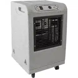
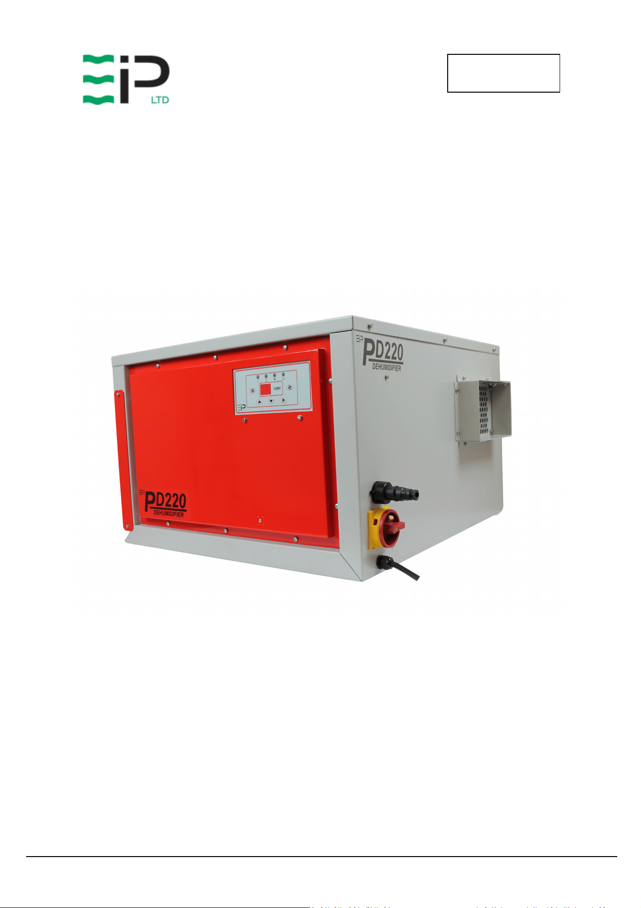
EBAC MODEL PD220
INDUSTRIAL DEHUMIDIFIER
OWNER’S MANUAL
Ebac Industrial Products, Inc.
700 Thimble Shoals Blvd, Suite 109
Newport News, VA. 23606-2575
Tel: (757) 873 6800 Fax: (757) 873 3632
Website www.ebacusa.com

PD
2
20
OWNERS MANUAL
Drawing No. :- TPC608
Issue :- 1
Date
:
-
12/06
/24
PD220
PACKAGE CONTENTS
Item Description Quantity
10151GY-US Dehumidifier 1
3014338 PVC tube – 12mm I/D 3M
3086101 Jubilee clip 1
3037866 6 Pin Plug 1
TPC608 Manual 1

PD
2
20
OWNERS MANUAL
Drawing No. :- TPC608
Issue :- 1
Date
:
-
12/06
/24
UNPACKING
Carefully remove the PD220 dehumidifier unit from its transit box and visually check for signs
of transit damage. If there is evidence of damage DO NOT attempt to operate the unit, call
your supplier for advice. Do not discard the packing, it will be useful when transporting the
dehumidifier unit in the future.
INTRODUCTION
The Ebac PD220 industrial dehumidifier removes moisture from the air through the
refrigeration process.
The Ebac PD220 is basically comprised of:
1) A compressor
2) A refrigerant evaporator coil
3) A refrigerant condenser coil
4) One circulation fan
5) A humidistat
6) A cabinet to house the above components
The fan draws the moist air through the cold evaporator coil which cools the air below its dew
point. Moisture forms on the evaporator coil and is collected in the condensate tray which is
equipped with a permanent drain. The cooled air then passes through the hot condenser coil
where it is reheated using the same energy removed during the cooling phase, plus the
additional heat generated by the compressor. The air is therefore discharged from the
dehumidifier at a slightly higher temperature with a lower absolute humidity than with which it
entered. Continuous circulation of air through the dehumidifier gradually reduces the relative
humidity within the area.
The dehumidifier is a rugged, reliable drying unit designed to operate effectively over a broad
range of temperature and humidity conditions.
The dehumidifier uses an internally mounted adjustable humidistat to enable you to select the
level of dryness.
The unit can also be used with an external humidistat or the EIPL touch display panel (via the 6
pin connector) to control the level of dryness.

PD
2
20
OWNERS MANUAL
Drawing No. :- TPC608
Issue :- 1
Date
:
-
12/06
/24
SPECIFICATIONS
M
ODEL
:
Ebac PD220
H
EIGHT
:
17.5” (443mm)
W
IDTH
:
27.5” (700mm)
D
EPTH
:
26” (660mm)
W
EIGHT
:
165 lbs (75Kg)
A
IRFLOW
:
664 CFM (1130 M3/hr)
P
OWER
:
2.1Kw
P
OWER
S
UPPLY
:
220V / 60Hz / 1ph
F
INISH
:
Powder-coated Epoxy
R
EFRIGERANT
T
YPE
/Q
TY
:
R410a / 49.4oz (1.4Kg)

PD
2
20
OWNERS MANUAL
Drawing No. :- TPC608
Issue :- 1
Date
:
-
12/06
/24
INSTALLATION
POSITIONING:
Position the dehumidifier unit in the center of the room to be conditioned if at all possible.
However, if a damp patch is particularly apparent the outlet grille should be pointed towards it
if possible.
This unit can also be used in a duct system where applicable, please see the diagrams on the
following pages which identify the overall sizes of the unit and also the mounting points.
Connect the drainage outlet to a suitably sized hose and run the hose to a permanent drain.
Connect the unit power cable to a grounded power source.
NOTE:
Both inlet grille and outlet grille of the dehumidifier unit must have clear space around them
and not be obstructed in anyway. For correct installation and operation, the unit inlet and
outlet must have a clearance of 0.5M from all adjacent surfaces and or structures.
Optional Control Methods
1. External Humidistat
• Connections for an external humidistat are available on the 6 pin connector above the
main isolator.
• The remote humidistat should have a normally open set of contacts which close on
humidity rise.
• This connection is low voltage low current, suggested cable specification 2 core 16/0.2
(0.5mm) screened cable.
• Connection is across pins 5 and 6 of the 6 pin connector
• The Jumper on the main control board should be removed from position “E” to allow
this feature to operate.
PD
2
20
OWNERS MANUAL
Drawing No. :- TPC608
Issue :- 1
Date
:
-
12/06
/24
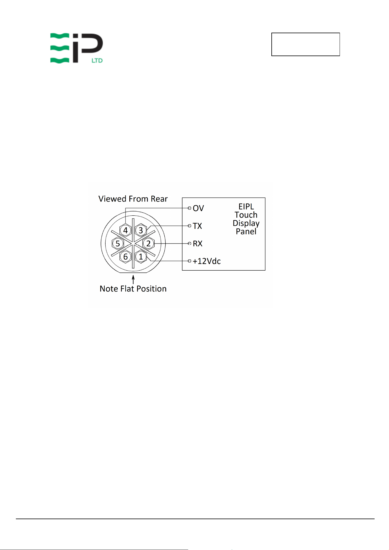
2. EIPL Touch Display Panel
• RS232 connections for the EIPL touch display panel are available on the 6 pin connector
above the main isolator.
• Suggested cable specification 4 core 16/0.2 (0.5mm) screened cable.
• Connection details:-
o Free Socket - Pin 1 - +12Vdc
o Free Socket - Pin 2 - RX
o Free Socket - Pin 3 - TX
o Free Socket - Pin 4 - 0V
PD
2
20
OWNERS MANUAL
Drawing No. :- TPC608
Issue :- 1
Date
:
-
12/06
/24
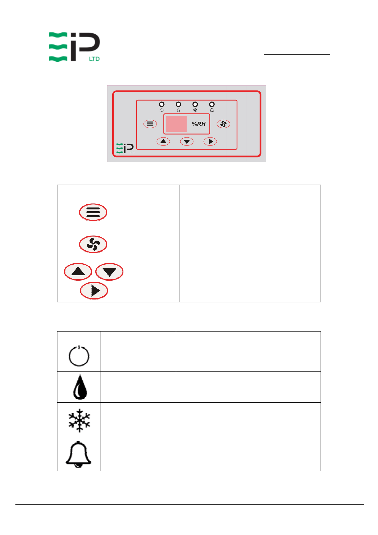
OPERATION
Button / Ledgend Function Description
Menu
Cycle through menu options and adjust the
desired set point. See below for list of menu
options
Recirculation
Select recirculation fan or dehumidification
mode
Navigation
Adjust the humidity set point UP/DOWN and
enter to confirm
Indicator Function Description
ON/OFF Green – On
Drying / Recirculation
Blue – Flashing – Drying Required
Blue – Solid – Drying On
Green – Solid – Recirculation Mode (Fan Only)
Defrost
Yellow – Flashing – Defrost mode selected
Yellow – Solid – Defrosting in progress
Alarm Red – Solid – Fault - High RH

PD
2
20
OWNERS MANUAL
Drawing No. :- TPC608
Issue :- 1
Date
:
-
12/06
/24
Menu Options
Pressing the Menu button cycles through the following pages of information.
Menu Options when dehumidifying mode is selected
Menu Display Information
1 Set RH
Using the Up / Down Keys adjust the humidity to the desired set-
point, pressing the Enter key to accept and save.
2 Temperature Indicates the current room temperature.
3 Coil Temp Shows the current coil temperature. (< -9degC display “—“)
4 Time To Start Displays the time to start drying (mins) or “on” if already drying
5 Time To Defrost
If defrost mode is selected, this option shows the remaining time
until defrost will occur. The yellow defrost light will be flashing
indicating a defrost is required.
6 Time In Defrost
If defrost is currently occurring, the yellow defrost light will be
solid, and the display will show the time remaining before
defrost ends.
Defrost not required or active the display will show “—“
Notes on Time values above
2 digits no decimal point indicates a time > 10mins
2 digits with a decimal point indicates mins and tenths of a min, ie 8.5 = 8mins 30 secs
Menu Options when recirculation mode is selected
Menu Display Information
1 Humidity Indicates the current room Humidity.
Operation
Plug the unit into a suitable wall socket and power on.
Set the Yellow/Red isolator switch to ON.
Note the Power On Indicator shows Solid Green.
To prevent the compressor starting too quickly after being powered down, there is an inbuilt
compressor off timer. This delayed start prevents the compressor for restarting for 6 minutes after
being switched off. Note this feature is reset when the isolator is set to OFF or power is removed from
the unit.
The dehumidifier remembers the last mode of operation, and also the previously adjusted set point.

PD
2
20
OWNERS MANUAL
Drawing No. :- TPC608
Issue :- 1
Date
:
-
12/06
/24
Once the dehumidifier is started, the drying / recirculation light will indicate the selected mode or
operation.
Adjust the mode, as required. (Recirculation or Drying).
In drying mode, the display will show the room humidity level.
In recirculation mode the display shows the current room temperature.
Using the Menu Key cycle through the menu options to the Set RH page, using the up/down and enter
keys adjust the humidity to the desired level.
The dehumidifier will now self-regulate to maintain the desired humidity level. The unit will
automatically defrost as needed. In warmer climates defrost is not required, allowing the dehumidifier
to continually dry.
If, after carrying out the above procedures, the appliance does not appear to
function properly, refer to the Trouble Shooting section, which follows, or contact
EIPL.

PD
2
20
OWNERS MANUAL
Drawing No. :- TPC608
Issue :- 1
Date
:
-
12/06
/24
ROUTINE SERVICE
WARNING: ENSURE THAT THE POWER CORD TO THE MACHINE HAS BEEN
DISCONNECTED BEFORE CARRYING OUT ROUTINE SERVICE. THE
SERVICING AND REPAIR OF THIS UNIT SHOULD ONLY BE CARRIED
OUT BY A SUITABLY QUALIFIED PERSON.
To ensure continued full efficiency of the dehumidifier, maintenance procedures should be
performed as follows:
1. Clean the surface of the evaporator and condenser coils by blowing the dirt out
from behind the fins with compressed air. Hold the nozzle of the air hose away
from the coil (approx 6”) to avoid damaging the fins. Alternatively, vacuum clean
the coils.
WARNING: DO NOT STEAM CLEAN REFRIGERATION COILS.
2. Check that the fan is firmly secured to the motor shaft and that the fan rotates
freely. The fan motor is sealed for life and therefore does not need oiling.
3. To check the refrigerant charge, run the unit for 15 minutes and briefly remove the
cover. The evaporator coil should be evenly frost coated across its surface. At
temperatures above 70°F, the coil may be covered with droplets of water rather
than frost. Partial frosting accompanied by frosting of the thin capillary tubes,
indicates loss of refrigerant gas or low charge.
4. Check all wiring connections.
I
F ANY OF THE PRECEDING PROBLEMS OCCUR
,
CONTACT THE
E
BAC
S
ERVICE
C
ENTER PRIOR TO
CONTINUED OPERATION OF THE UNIT TO PREVENT PERMANENT DAMAGE
.

PD
2
20
OWNERS MANUAL
Drawing No. :- TPC608
Issue :- 1
Date
:
-
12/06
/24
REPAIRS
1. Should an electrical component fail, consult the Factory Service Center to obtain the
proper replacement part.
2. If refrigerant gas is lost from the machine, it will be necessary to use a refrigeration
technician to correct the fault. Contact the Factory Service Center prior to initiating
this action.
Any competent refrigeration technician will be able to service the equipment. The
following procedure must be used:
a. The source of the leak must be determined and corrected.
b. The machine should be thoroughly evacuated before recharging.
c. The unit must be recharged with refrigerant measured accurately by weight.
d. For evacuation and recharging of the machine, use the crimped and brazed
charging stub attached to the side of the refrigerant compressor.
The charging stub should be crimped and rebrazed after servicing. N
EVER
allow
permanent service valves to be fitted to any part of the circuit. Service valves
may leak causing further loss of refrigerant gas.
3. The refrigerant compressor fitted to the dehumidifier is a durable unit that should
give many years of service. Compressor failure can result from the machine losing
its refrigerant gas. The compressor can be replaced by a competent refrigeration
technician.
Failure of the compressor can be confirmed by the following procedure:
a. Establish that power is present at the compressor terminals using a voltmeter.
b. With the power disconnected, check the continuity of the internal winding by
using meter across the compressor terminals. An open circuit indicates that the
compressor should be replaced.
c. Check that the compressor is not grounded by establishing that a circuit does
not exist between the compressor terminals and the shell of the compressor.

PD
2
20
OWNERS MANUAL
Drawing No. :- TPC608
Issue :- 1
Date
:
-
12/06
/24
TROUBLESHOOTING
S
YMPTOM
C
AUSE
R
EMEDY
Unit inoperative 1. no power to unit
1. Check the power from the power
supply panel
Little or no airflow
1. Loose fan on shaft
2. Fan motor burnt out
3. Dirty refrigeration coils
4. Loose electrical wiring
1. Tighten fan
2. Replace the fan motor
3. See Routine Maintenance Section
4. Check the wiring diagram to find
fault and repair
Little or no water extraction
1. Insufficient air flow
2. Compressor fault
3.
Loss of refrigerant gas
1. Check all of the above
2. Contact the Factory Service Center
3.
Contact the Factory Service Center
Unit vibrates excessively
1. Loose compressor mounts
2. Damaged fan
1. Tighten the nuts on the compressor
mounts
2. Replace fan
Water flooding inside the
machine
1. Drain pipe blocked/frozen
2. Drain pipe too high
1. Clear the obstruction
2. Ensure that no section of the drain
hose is above the level of the water
outlet
Ebac Industrial Products, Inc.
700 Thimble Shoals Blvd, Suite 109
Newport News, VA. 23606-2575
Tel: (757) 873 6800 Fax: (757) 873 3632
Website www.ebacusa.com
PD
2
20
OWNERS MANUAL
Drawing No. :- TPC608
Issue :- 1
Date
:
-
12/06
/24
SPARE PARTS LIST
Description
Part Number
Product Part N
umber
101
51
GY
-
US
Controls Display PCB
1619536
Humidity Sensor PCB
1619526
PCB Timer
1619531
PCB connecting cable (700mm)
2013748
Evaporator Coil
2015026
Condenser Coil
201502
7
Filter
2015028
Keypad Label
2015031
Coil Bracket Blanking Foam
2018724
10mm ID insul tube
3014301
Reversing Valve
3020834
Filter Dryer
3020957
Pressure Stat
3021154
Solenoid Coil
3030454
Mains Cable
3031202
Terminal Block
3031403
25mm Open Grommet
3032111
M16 Cable Gland
3032511
M16 Gland Nut
3032512
Coil Sensor
30
35142
Humidity Sensor Housing
3035164
6 Pin Socket
3037865
6 Pin Plug
3037866
Fan Wheel
3040247
Fan Inlet Ring
3040248
Jubilee Clip
3086101
PCB Mounting Pin
3101413
Contactor
3930736
Isolator
3932332
Light Pipe Lens
3931732
Compressor Capacitor
393351
2
Mains Plug
3934516
PCB Connecting Cable (300mm)
3934519
PCB
–
Plug Cable
3935428
Condensate Drain Tube
3944115
Compressor
394494
9
Fan Motor
3947037
Capillary
3014252

PD
2
20
OWNERS MANUAL
Drawing No. :- TPC608
Issue :- 1
Date
:
-
12/06
/24
WARNINGS
This appliance can be used by children from 8 years and above and persons with reduced
physical, sensory or mental capabilities or lack of experience and knowledge if they have been
given supervision or instruction concerning use of the application in a safe way and understand
the hazards involved.
Children shall not play with the appliance.
Cleaning and user maintenance shall not be made by children without supervision.
If the SUPPLY CORD is damaged, it must be replaced by the manufacturer, its service agent or
similarly qualified person in order to avoid hazard.
This product contains fluorinated greenhouse gases covered by the Kyoto Protocol. The
refrigeration system is hermetically sealed.
The Global Warming Potential (GWP) of refrigerants used in products manufactured by Ebac
Industrial Products Ltd is as follows
R410a – 2088
For type and weight of refrigerant contained in this unit, please refer to the product data label
Due to the high pressures within the refrigeration circuit, under no circumstances must direct
heat be applied to the evaporator coil in an attempt to remove the build-up of ice.
No attempt should be made to cut open any part of the refrigeration circuit due to high
pressures and gas involved.
If the unit is switched off at the mains power supply for any reason, the unit must be allowed
to stand at rest for at least three minutes before restarting.

PD
2
20
OWNERS MANUAL
Drawing No. :- TPC608
Issue :- 1
Date
:
-
12/06
/24

PD
2
20
OWNERS MANUAL
Drawing No. :- TPC608
Issue :- 1
Date
:
-
12/06
/24
UK Head Office
Ebac Industrial Products Ltd
St Helens Trading Estate
Bishop Auckland
County Durham
DL14 9AD
Tel: +44 (0) 1388 664400
Fax: +44 (0) 1388 662590
www.eipl.co.uk
American Sales Office
Ebac Industrial Products Inc
700 Thimble Shoals Blvd.
Suite 109, Newport News
Virginia, 23606-2575
USA
Tel: +01 757 873 6800
Fax: +01 757 873 3632
www.ebacusa.com
sales@ebacusa.com