Page 1 of 16
Drawing : - TPC180
Issue : - 2
Date : - 07/10/03
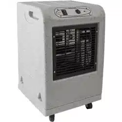
SPP6A
DEHUMIDIFIER
OWNER’S MANUAL
www.eipl.co.uk

Page 2 of 16
Drawing : - TPC180
Issue : - 2
Date : - 07/10/03
UNPACKING
Carefully remove the SPP6A Dehumidifier unit from its transit box and visually
check for signs of transit damage. If there is evidence of damage DO NOT
attempt to operate the unit, call your supplier for advice. Do not discard the
packing; it will be useful when transporting the dehumidifier unit in the future.
INTRODUCTION
Dehumidifiers remove moisture from the air that is circulating through the unit.
The resulting reduction of relative humidity helps prevent rust, rot, mould,
mildew and condensation within the room, or other enclosed spaces where
the dehumidifier is used.
A dehumidifier consists of a motor-compressor unit, a refrigerant condenser,
an air circulating fan, a refrigerated surface, a means of collecting and
disposing the condensed moisture and a cabinet to house these components.
The fan draws air through the refrigerated surface and cools it below its dew
point, removing moisture which is collected and led away. The cool air then
passes the hot condenser, where it is reheated. With the addition of other
radiated heat the air is discharged into the room at a higher temperature but
lower relative humidity than when the air entered the unit. Continuous
circulation of the room air through the dehumidifier unit gradually reduces the
relative humidity in the room.
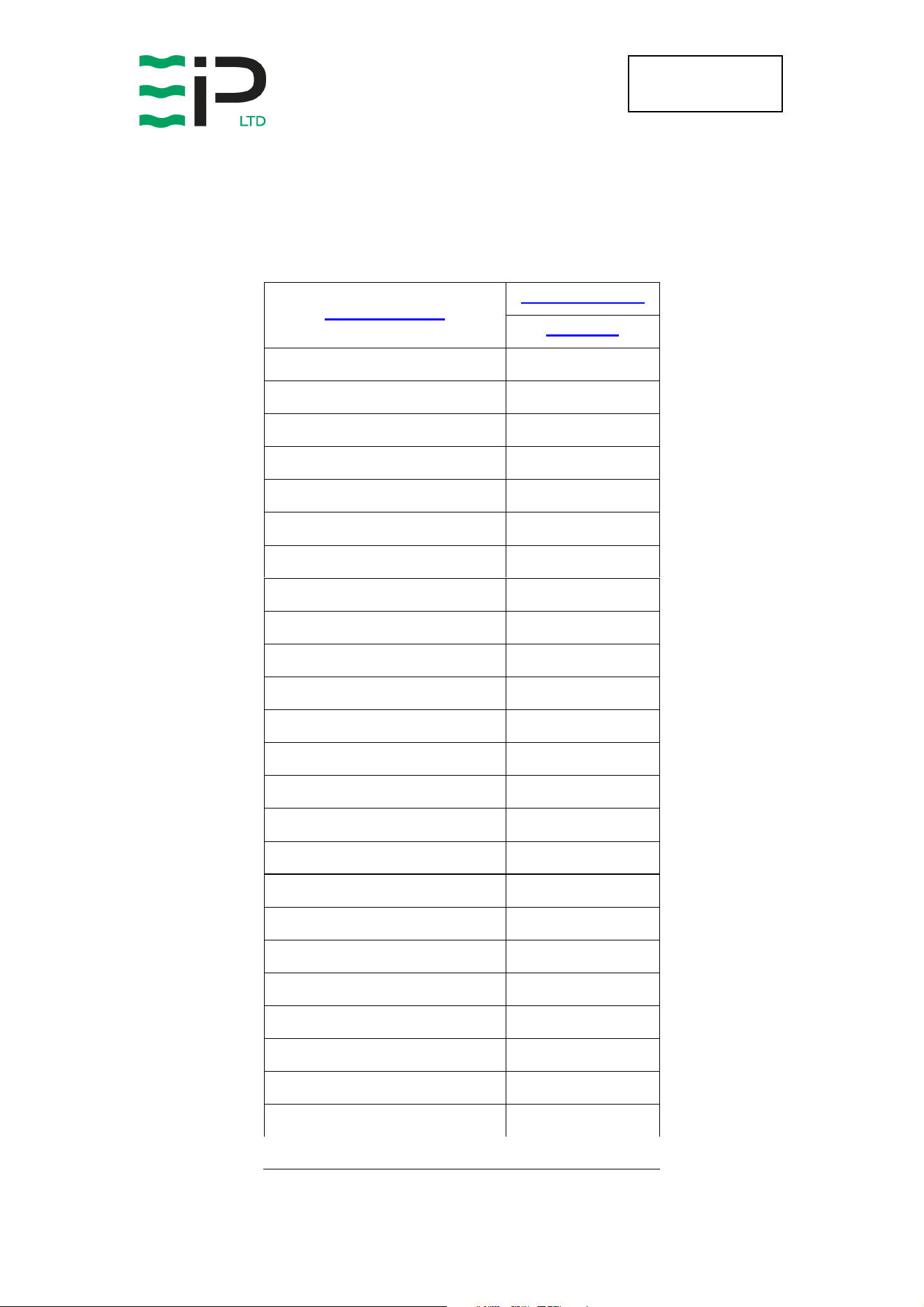
The SPP6A Dehumidifier is a robust, compact unit designed to control the
humidity in the enclosed space in which it is placed.
• The unit is thermally protected and will switch off for a period if the
maximum operating temperature of 50ºC is exceeded.
• The SPP6A has been designed for the exacting conditions which can
prevail in the medium to long term storage of mobile shelters and
vehicles. It combines lightness and compactness with high reliability
and strength.
• Handles contribute to its portability.
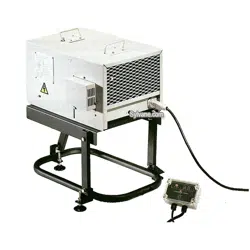
• A Dehumidifier stand (Part Number 1137500) is available to provide both
a level platform and an easy working height for the operational
personnel.
• The gas which is used inside the hermetically sealed refrigeration circuit
is R134A, which contains no CFC's and has therefore a zero ozone
depletion factor.
BUT under no circumstances should this gas be released into the
atmosphere, the unit should be serviced by trained personnel who will
re-claim any of the unwanted gas.

Page 3 of 16
Drawing : - TPC180
Issue : - 2
Date : - 07/10/03
SPECIFICATIONS
Model:
SPP6A
Length:
447mm
Width:
340mm
Height:
255mm
Weight:
28 Kg (Typically)
Paint Finish:
Light Grey
Power Supply:
115v ± 10%, 1 ph / 60Hz
Power Rating:
250-300W
Airflow:
250 M3/HR
Construction:
Welded 1.2m steel
chassis and covers
Portability:
Two folding carrying
handles.
Power Cable Length:
10 Meters
Water Drainage:
12mm outlet spigot
MONITOR BOX
L
ENGTH
:
120mm
W
IDTH
:
80mm
D
EPTH
:
55mm
3
N
EON
I
NDICATING AMPS
C
ONSTRUCTION
:
ABS/ Polycarbonate enclosure
designed in accordance with
IP65 standards.

Page 4 of 16
Drawing : - TPC180
Issue : - 2
Date : - 07/10/03
WATER EXTRACTION DUTY
TEMPERATURE
ºC
HUMIDITY
%
WATER
EXTRACTION
L/24HR
0 70 0.6
10 70 1.8
20 70 3.5
30 70 5.2
40 70 7.0
55 40 7.0
44 95 12.0

Page 5 of 16
Drawing : - TPC180
Issue : - 2
Date : - 07/10/03
INSTALLATION
POSITIONING:
Position the dehumidifier unit in the center of the room to be conditioned if at
all possible. However if a damp patch is particularly apparent the outlet grille
should be directed towards it.
NOTE: Both inlet grille and outlet grille of the dehumidifier unit must have
clear space around them and not be obstructed in anyway.
WIRING:
Connect the power mains cable/plug of the dehumidifier unit to a 15 Amp
power supply. As follows:-
115 Volt Supply
Brown Live
Blue Neutral
Green/Yellow Earth (ground)
DRAINAGE:
Connect a 12.5mm inside diameter hose to the condensate outlet pipe
(positioned centrally, beneath the air inlet grille). Secure the hose using a
worm drive clip. The hose should at no point be raised higher than the outlet
pipe. Failure to observe this requirement will result in flooding of the
dehumidifier unit.

Page 6 of 16
Drawing : - TPC180
Issue : - 2
Date : - 07/10/03
OPERATION
The operation of the dehumidifier is to remove moisture from the air by having
it condense on the cold tubes of the evaporator coil. The air then passes over
the hot condenser coil and returns to the conditioned space slightly warmer
and dryer than when it entered the dehumidifier unit.
AIR MOVING SYSTEM:
Air is drawn in through the inlet grille at the rear of the dehumidifier (below the
handle) and over the two heat exchanges (evaporator/condenser coils) under
the influence of the axial fan, which is driven by the motor. The operation of
the fan motor is to run continuously whenever power is supplied to the
dehumidifier. The fan motor used in the dehumidifier unit is induction
protected i.e. the motor is able to take stalled current without burning out the
motor windings.
DEFROST OPERATION:
If the ambient temperature of the room in which the dehumidifier unit is
conditioning falls below 15ºC ice will form on the evaporator coil as the air is
passed over it, after a time this build up of ice on the evaporator coil will effect
the efficiency of the unit, on its ability to maintain the required set conditions
for the room.
The SPP6A is therefore fitted with a defrost control device. This defrost
control device is timed to operate every 40mins, at which time, for
approximately 8mins the high pressure gas is diverted by means of a by-pass
valve to enter the evaporator coil. The effect of this high pressure gas entering
the evaporator coil is to melt any build up of ice on this coil. The melted ice is
collected and disposed of by means of the condensate tube.
HIGH TEMPERATURE CUTTOUT:
The SPP6A dehumidifier has been designed to work in ambient conditions of
10ºC and 50ºC. Should the temperature in the room become excessive a
thermostat within the compressor casing will open and dehumidifying will stop,
until the thermostat resets itself.

Page 7 of 16
Drawing : - TPC180
Issue : - 2
Date : - 07/10/03
WARNING:
• Due to the high pressures within the refrigeration circuit, under no
circumstances must direct heat be applied to the evaporator coil in an
attempt to remove the build up of ice.
• No attempt should be made to cut open any part of the refrigeration circuit
due to high pressures and gas involved. If the unit is switched off at the
mains power supply for any reason, the unit must be allowed to stand at
rest for at least three minutes before restarting. Failure to do so may cause
the unit to blow the fuses owing to the compressor due to there being a
refrigerant imbalance.

Page 8 of 16
Drawing : - TPC180
Issue : - 2
Date : - 07/10/03
SPECIAL FEATURES
CONTROL AND WARNING INDICATOR HUMIDISTAT
The SPP6A dehumidifier unit is fitted with a control panel fixed to the outside
of the dehumidifier cabinet, the panel incorporates two humidity’s, which
measure the relative humidity of the air within the room/space. The first
humidistat incorporates a pointer and a scale, and is adjustable to a set point.
The second humidistat has no pointer or scale, and is pre-set and fixed at the
factory at the customers requested set point.
FIRST HUMIDISTAT
The humidistat controls the on/off function of the dehumidifier unit, when the
relative humidity of the air in the room/space falls below the set point of the
humidistat the dehumidifier unit will switch off, but when the relative humidity
of the air within the room/space rises above the set point of the humidistat the
dehumidifier unit will switch on.
SECOND HUMIDISTAT
This humidistat which is factory pre-set at 60%RH is connected to a warning
indicating system. This warning indicating system will be monitored by the
customer and will indicate that the relative humidity of the air within the room
has risen above the pre-set 60%RH level due to a fault, either with the
dehumidifier unit or due to some other circumstance and requires attention of
a service engineer.
TEMPERATURE CONTROLLED DEFROST
The SPP6A dehumidifier unit is fitted with temperature sensitive device which
will operate in conjunction with the defrost control. In normal operation the
defrost control will come into operation every 40 minutes, this is to ensure that
there will be no build up of ice at lower temperatures, but where year round
conditions need to be maintained the dehumidifier unit will have to operate
across a wider range of temperatures. To ensure that the dehumidifier
operates at its most efficient this temperature sensitive device will restrict the
defrost operation to the times when the evaporator coil is at -2ºC.
INDICATOR BOX
The indicator box, which is sealed against water ingress, is connected to the
dehumidifier in the mains input cable; it has three indicating lamps mounted
under a transparent front panel.

Page 9 of 16
Drawing : - TPC180
Issue : - 2
Date : - 07/10/03
AMBER LAMP
This indicates that the dehumidifier unit is in stand by mode (the relative
humidity within the room/space is below the set point of the Control
humidistat) and mains power is applied.
GREEN LAMP
This indicates that the dehumidifier unit is operating (the relative humidity
within the room/space is above the set point of the Control humidistat). The
relative humidity above which the dehumidifier unit will operate can be set by
adjusting the humidistat knob, which is positioned on the inside of the
dehumidifier unit.
RED LAMP
This indicates that the relative humidity within the room/space has risen above
the pre-set 60% RH of the second humidistat and requires attention of a
service engineer.

Page 10 of 16
Drawing : - TPC180
Issue : - 2
Date : - 07/10/03
ROUTINE MAINTENANCE
To ensure continued full efficiency of the dehumidifier, maintenance
procedures should be performed as follows:
1. Clean the surface of the evaporator and condenser coils by blowing
the dirt out from behind the fins with compressed air. Hold the
nozzle of the air hose away from the coil (approx 6”) to avoid
damaging the fins. Alternatively, vacuum clean the coils.
2. Check that the fan is firmly secured to the motor shaft and that the
fan rotates freely. The fan motor is sealed for life and therefore
does not need oiling.
3. To check the refrigerant charge, run the unit for 15 minutes and
briefly remove the cover. The evaporator coil should be evenly frost
coated across its surface. At temperatures above 25°C, the coil
may be covered with droplets of water rather than frost. Partial
frosting accompanied by frosting of the thin capillary tubes,
indicates loss of refrigerant gas or low charge.
4. Check all wiring connections.
5. To check the operation of the defrost system, switch the machine
on and leave it running for approximately 45 minutes. The machine
will then enter “Hot Gas” defrost mode for approximately 4 minutes
before returning to normal operation. If the unit will not defrost, the
printed circuit timer board may be defective or the by-pass valve
may be inoperable.
I
F ANY OF THE PRECEDING PROBLEMS OCCUR
,
CONTACT THE
E
BAC
S
ERVICE
C
ENTER PRIOR TO CONTINUED OPERATION OF THE UNIT TO
PREVENT PERMANENT DAMAGE
.
WARNING:
ENSURE THAT THE POWER CORD TO THE MACHINE HAS
BEEN DISCONNECTED BEFORE CARRYING OUT ROUTINE
MAINTENACE ON ITEMS 1, 2, 3, 4, AND 5.
WARNING:
DO NOT STEAM CLEAN REFRIGERATION COILS

Page 11 of 16
Drawing : - TPC180
Issue : - 2
Date : - 07/10/03
REPAIRS
1. Should an electrical component fail, consult the Factory Service
Center to obtain the proper replacement part.
2. If refrigerant gas is lost from the machine, it will be necessary to use
a refrigeration technician to correct the fault. Contact the Factory
Service Center prior to initiating this action.
Any competent refrigeration technician will be able to service the
equipment. The following procedure must be used:
a. The source of the leak must be determined and corrected.
b. The machine should be thoroughly evacuated before
recharging.
c. The unit must be recharged with refrigerant measured
accurately by weight.
d. For evacuation and recharging of the machine, use the crimped
and brazed charging stub attached to the side of the refrigerant
compressor.
The charging stub should be crimped and rebrazed after
servicing. N
EVER
allow permanent service valves to be fitted to
any part of the circuit. Service valves may leak causing further
loss of refrigerant gas.
3. The refrigerant compressor fitted to the dehumidifier is a durable
unit that should give many years of service. Compressor failure can
result from the machine losing its refrigerant gas. The compressor
can be replaced by a competent refrigeration technician.
Failure of the compressor can be confirmed by the following
procedure:
a. Establish that power is present at the compressor terminals
using a voltmeter.
b. With the power disconnected, check the continuity of the internal
winding by using meter across the compressor terminals. An
open circuit indicates that the compressor should be replaced.
c. Check that the compressor is not grounded by establishing that
a circuit does not exist between the compressor terminals and
the shell of the compressor.

Page 12 of 16
Drawing : - TPC180
Issue : - 2
Date : - 07/10/03
TROUBLESHOOTING
S
YMPTOM
C
AUSE
R
EMEDY
Little or no airflow
1. Loose fan on shaft
2. Fan motor burnt out
3. Dirty refrigeration coils
4. Loose electrical wiring
5. Control humidistat either
set too high or malfunctioning
1. Tighten fan
2. Replace the fan motor
3. See Routine Maintenance
Section
4. Check the wiring diagram
to find fault and repair
5. Contact the Factory
Service Center
Little or no
dehumidifying effect
1. Insufficient air movement
2. Compressor not running:-
a) No power supply to
compressor
b) Compressor tripped on
internal overload – allow reset
time of two hours
c) Compressor burnt out
d) Loss of refrigerant
(resulting in hot compressor)
e) Humidistat either set too
high or malfunctioning
f) Blocked filter dryer
1. Check all of the above
2. Contact the Factory
Service Center
Page 13 of 16
Drawing : - TPC180
Issue : - 2
Date : - 07/10/03
SPP6A
SPARE PARTS LIST
P
ART
N
UMBERS
D
ESCRIPTION
1139800
Compressor 3022143
Compressor OH Protector 3021538
Comp Relay 3021528
Comp Box Cover 3021518
Condenser Coil 3020740
Evaporator Coil 1135707
Filter Dryer 3020937
Fan Motor 3035767
Fan Blade 3040101
Drain Tube 3014338
Worm Drive Clip 3086101
Clip Nut 3080501
Control Humidistat 3031528
Indicator Humidistat 2135727
Male Contacts 3033814
Male insert 3033809
Indicator Box 1135710
Cable Gland 3032511
Cable Gland Nut 3032512
Hood 3033811
Female Insert 3033810
Cable Seal 3033813
Indicator Housing 2135713
Female Contact 3033815

Page 14 of 16
Drawing : - TPC180
Issue : - 2
Date : - 07/10/03
"This product contains fluorinated greenhouse gases covered by the Kyoto Protocol. The
refrigeration system is hermetically sealed.
The Global Warming Potential (GWP) of refrigerants used in products manufactured by Ebac
Industrial Products Ltd is as follows
R134a – 1300
R407c – 1610
For type and weight of refrigerant contained in this unit, please refer to the product data label"
Spare parts available online
www.EIPLDIRECT.com
Green Neon 3036637
Red Neon 3036636
Mains Cable 3031225
Control Cable 3031227
Bypass Valve 3020811
Solenoid Coil 3030421
Frostat 3031516
Timer 1618200
PCB Mounting Clips 3101413

Page 15 of 16
Drawing : - TPC180
Issue : - 2
Date : - 07/10/03

Page 16 of 16
Drawing : - TPC180
Issue : - 2
Date : - 07/10/03
UK Head Office
Ebac Industrial Products Ltd
St Helens Trading Estate
Bishop Auckland
County Durham
DL14 9AD
Tel: +44 (0) 1388 664400
Fax: +44 (0) 1388 662590
www.eipl.co.uk
American Sales Off
ice
Ebac Industrial Products Inc
700 Thimble Shoals Blvd.
Suite 109, Newport News
Virginia, 23606-2575
USA
Tel: +01 757 873 6800
Fax: +01 757 873 3632
www.ebacusa.com
German Sales Office
Ebac Industrial Products Ltd
Miraustra 64 – 66
13509
Berlin
Germany
Tel: +49 3043 557241
Fax: +49 3043 557240
www.eip-ltd.de