
INSTALLATION GUIDE
for the
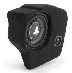
SB-GM-5GSUV/10TW3
SKU# 94698
2021-Up Chevrolet / GMC Full-Size SUVs
• Installation requires appropriate tools and safety equipment.
Professional installation is recommended.
• If you prefer to perform your own installation, please read this
installation guide completely before beginning.
• Before cutting or drilling, check for potential obstacles behind
mounting surfaces.
• Mount this product securely to prevent damage or injury in
severe conditions.
INSTALLATION
DIFFICULTY:
ESTIMATED TIME:
1 HOUR
Enclosure Type: Sealed
Driver Type: 10TW3-D4
Nominal Impedance: 2 ohms
Continuous Power Handling: 400 watts (RMS method)
Continued on Next Page
2
5
OUT
OF
SB-GM-5GSUV/10TW3 INSTR_SKU# 011569
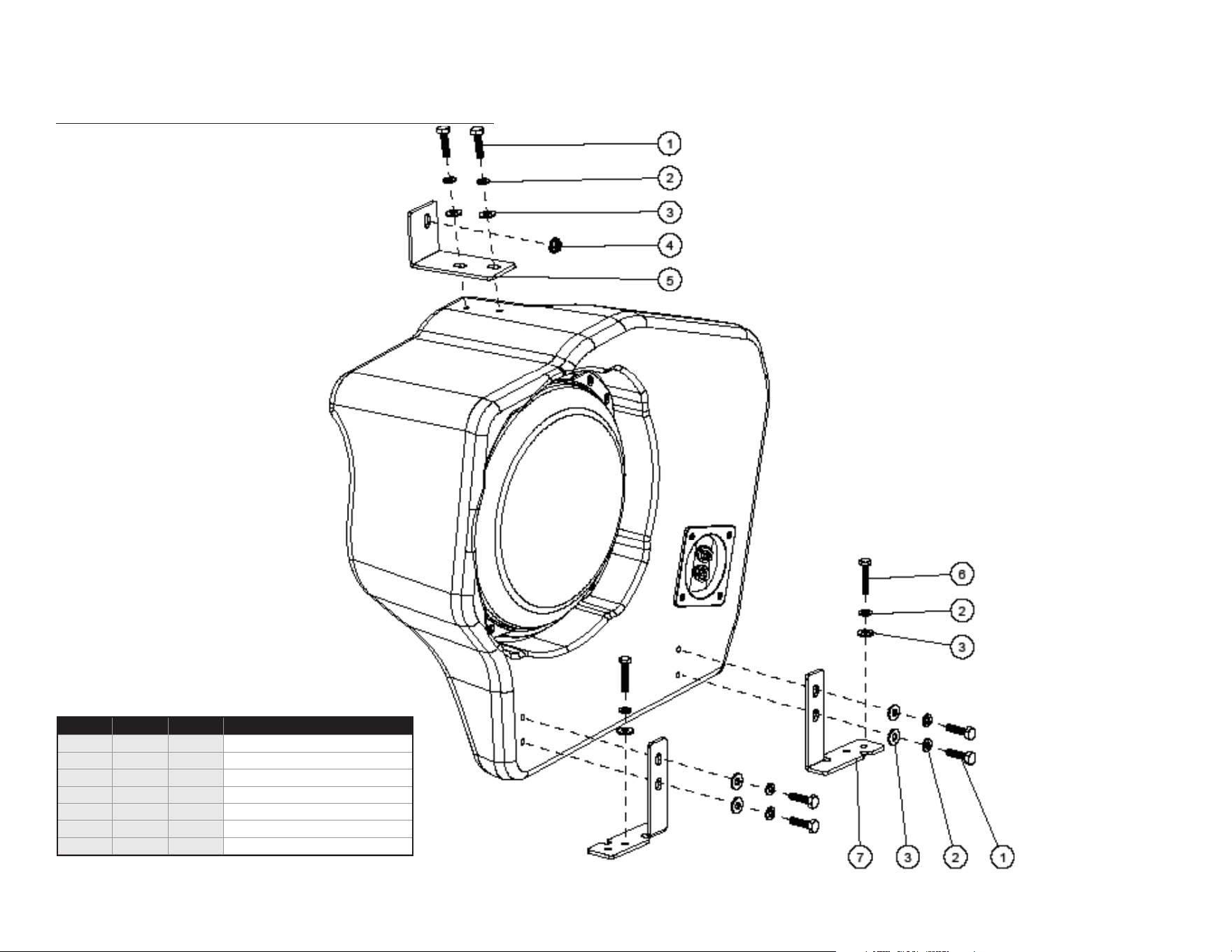
INCLUDED HARDWARE
Continued on Next Page
Page 2 • JL Audio, Inc., 2022
SB-GM-5GSUV/10TW3 INSTR_SKU# 011569
BOM ID Qty SKU Description
1 6 150042 1/4 - 20 x 1” Hex Head Screw
2 8 151098 1/4” Split Lock Washer
3 8 151021 1/4” Flat Washer
4 1 150074 M6 - 1 mm Serrated Flange Nut
5 1 154446 Top Bracket
6 2 154448 M6 - 1 x 30 mm Hex Head Screw
7 2 154447 Bottom Bracket
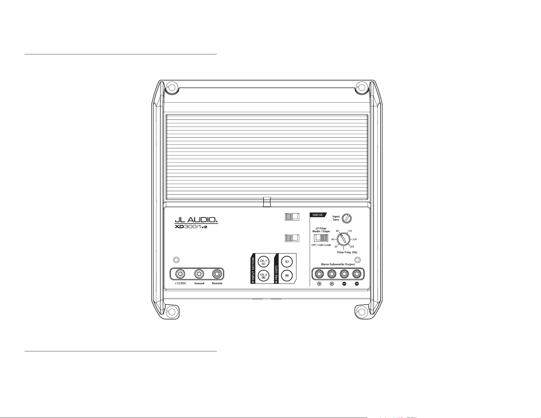
POWER RECOMMENDATION
JL Audio recommends high quality ampliers such as the JL Audio XD300/1v2. The diagram below shows the recommended crossover settings for the XD300/1v2. For a detailed description of the
amplier settings, consult the owner’s manual for the amplier. If another amplier is being used, please reference this illustration and use similar settings on that amplier.
CONNECTIONS
Using quality power, signal, and speaker wire is essential in ensuring the performance of your Stealthbox®. JL Audio recommends using a 4 AWG power kit such as the XD-PCS4-1B for your
Stealthbox® amplier. Other kits are available should you be using more than one amplier. Signal wire such as the JL Audio Premium Audio Interconnect Cables should be used to provide signal for
both channels of the amplier. JL Audio recommends using 12 AWG speaker wire for subwoofers such as our XC-BCS12-25.
Continued on Next Page
Page 3 • JL Audio, Inc., 2022
SB-GM-5GSUV/10TW3 INSTR_SKU# 011569
Rem.
|
Oset
|
Signal
Input Voltage
Low
|
High
Turn-On Mode
Monoblock Subwoofer Amplifier
Page 4 • JL Audio, Inc., 2022 Continued on Next Page
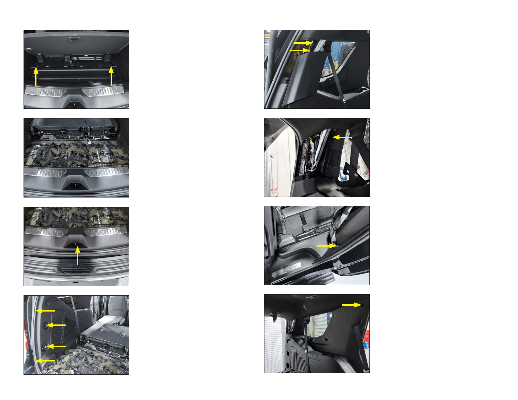
STEP 8
Pry and remove the indicated bolt cover from
the panel, exposing the Torx bolt
underneath. Remove the exposed Torx bolt.
Pry the panel from the vehicle, releasing it from
the perimeter clips.
STEP 7
Release the seat belt bolt cover from the
bottom of the driver side second row seat belt,
exposing the bottom seat belt bolt. Remove
the exposed lower seat belt bolt.
STEP 6
Remove the exposed bolt from the rear
pillar speaker panel. Pry the panel to release it
from the panel clips.
Disconnect the speaker harness from the rear
of the pillar speaker and set the panel aside.
STEP 5
Pry and unclip the upper panel to release.
Remove the indicated bolt and detach the
indicated bungee clip. Set the panel aside.
STEP 4
Pry the indicated cargo loop bolt cover open,
exposing the Torx bolt underneath. Remove
the exposed Torx bolt.
Unscrew and remove the indicated plastic nut.
Pry and release the weatherstripping from the
rear edge of the panel.
STEP 3
Pry and remove the plastic lock striker cover
from the rear sill panel.
Unclip the rear sill panel’s perimeter clips and
lift it from the floor. Set the panel aside.
STEP 2
Lift the cargo floor from the vehicle and
set aside.
STEP 1
Flip the floor cargo door open. Unscrew and
remove the two indicated plastic nuts.
SB-GM-5GSUV/10TW3 INSTR_SKU# 011569
Page 5 • JL Audio, Inc., 2022 Continued on Next Page
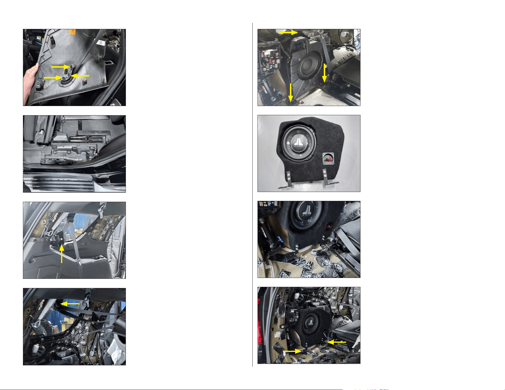
STEP 16
Create two screw assemblies by sliding a
supplied 1/4” Lock Washer and 1/4” Flat Washer
onto a M6 - 1 x 30 mm Hex Head Screw.
Use the two assemblies to attach the Bottom
Brackets to the factory subwoofer enclosure
mounting bolt holes in the floor. Hand tighten
the screw assemblies. Connect speaker cable
to the terminal cup of the enclosure, and route
the cable as necessary.
STEP 15
Place the Stealthbox® into the vehicle, aligning
the Bottom Bracket notches to the factory floor
studs as shown in the image.
STEP 14
Create four screw assemblies by sliding a
supplied 1/4” Lock Washer and 1/4” Flat Washer
onto a 1/4 - 20 x 1” Hex Head screw.
Referring to Page 2 as a guide, orient two
Bottom Brackets as shown in the
illustration. Pass two screw assemblies through
each Bottom Bracket into the threaded inserts
at the bottom of the Stealthbox® and
hand tighten.
STEP 13
Uninstall the factory subwoofer by removing
the single indicated nut from the top bracket
and the two indicated bolts from the
bottom brackets.
Disconnect the factory subwoofer wiring
harness and set the factory subwoofer aside.
STEP 12
Open the third row seat belt upper bolt cover
and remove the exposed bolt. Guide the third
row seatbelt upper through the rear panel to
free the panel from the vehicle completely.
Set the rear panel aside.
STE P 11
Unclip and remove the third row seatbelt
guide panel.
Unclip the rear panel from its perimeter
mounting clips.
Note: If the vehicle is equipped with a rear
panel USB port, unclip the USB port from the
panel and disconnect its wiring harness.
STEP 10
Remove the driver side rear door sill panel by
prying it up from the floor, releasing it from
the clips. Set the panel aside.
STEP 9
Flip the panel over that was removed in STEP
8. The seat belt guide trim is attached to the
panel by plastic tabs. Carefully detach the seat
belt guide trim from the panel by unlatching
the plastic tabs.
Guide the unbolted seat belt bottom through
the panel and set aside.
SB-GM-5GSUV/10TW3 INSTR_SKU# 011569
Page 6 • JL Audio, Inc., 2022
MID/HIGH FREQUENCY DRIVER FITMENT
A variety of JL Audio coaxial and component systems will t in the factory speaker locations of your vehicle.
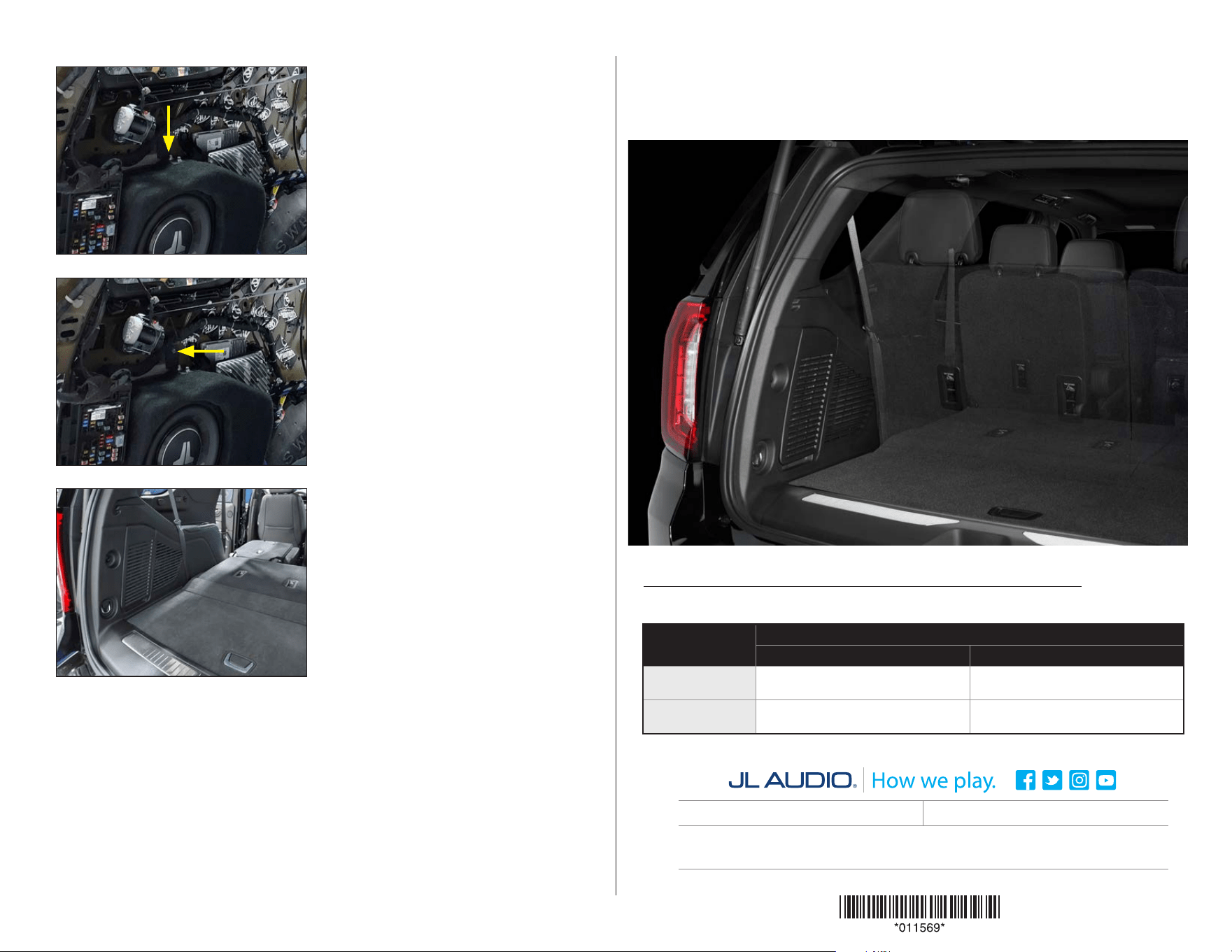
CONGRATULATIONS!
You have completed the installation for this model! Enjoy your new Stealthbox®!
SB-GM-5GSUV/10TW3 INSTR_SKU# 011569
STEP 19
Reinstall all factory parts and panels.
STEP 18
Align the top hole of the Top Bracket to the
factory upper subwoofer enclosure mounting
stud. Use the supplied M6 - 1 mm Serrated
Flange Nut to attach the Top Bracket to
the vehicle.
Once all mounting brackets are aligned, fully
tighten all bracket screw assemblies to the
enclosure and the Top Bracket M6 - 1 mm
Serrated Flange Nut to the factory stud.
STEP 17
Create two screw assemblies by sliding a
supplied 1/4” Lock Washer and 1/4” Flat Washer
onto a 1/4 - 20 x 1” Hex Head screw.
Referring to Page 2 as a guide, orient the Top
Bracket as shown in the illustration. Pass two
screw assemblies through the Top Bracket
into the threaded inserts at the top of the
Stealthbox® and hand tighten.
All specifications are subject to change without notice. “JL Audio®” and “How we play®” are registered trademarks of JL Audio, Inc. “Ahead of the Curve” and its respective logo are trademarks
of JL Audio, Inc.
Printed in USA • ©2022 JL Audio, Inc. • For more detailed information please visit us online at www.jlaudio.com.
(954) 443-1100
www.jlaudio.com
JLA-SKU# 011569 • ver. 8.16.22 • 10369 NORTH COMMERCE PARKWAY • MIRAMAR, FLORIDA • 33025 • USA
®
Location / OEM
Speaker Size
Suggested JL Audio Speaker Models
Coaxial Models Component Models
Front Doors /
6 x 9-inch
C-690x
(1)
, C1-690tx
(1)
, C2-690tx
(1)
C2-650x
(1)
, C5-650x
(1)
C1-690
(1)
, C1-650
(1)
,
C2-650
(1)
,
C3-650
(1)
, C5-650
(1)
, C7-650cw
(1,2)
Rear Doors /
6.5-inch
C1-650x, C2-650x, C5-650x
C1-650, C2-650, C3-650,
C5-650, C7-650cw
(2)
1 - Installation may require adaptor, 2 - Component woofer only