
2
Introduction
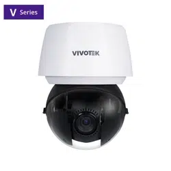
The SD9387-EHL, SD9394-EHL, and SD9367-EHL are high-performance outdoor PTZ (pan-tilt-zoom) speed
dome network cameras developed by VIVOTEK for wide-area surveillance applications. Designed for
scenarios such as city streets, highways, transportation hubs, and large open facilities, these cameras
offer a combination of long-range optical zoom, intelligent video analytics, and advanced image sensors
to ensure clear, detailed, and effective monitoring around the clock.
Both models use Sony Starvis II CMOS image sensors for superior low-light performance. The SD9394-
EHL features an 8MP sensor and a 200-meter IR illuminator for excellent night visibility, while the SD9387-
EHL, with a 5MP sensor, ensures dependable imaging in a wide range of lighting conditions.
Supporting H.265 with Smart Stream III, the cameras provide efficient bandwidth and storage usage. With
30x optical zoom , WDR, and enclosures rated IP66, IK10, and NEMA 4X, they ensure reliable operation
from -40°C to 55°C across a wide range of outdoor conditions.
A major advancement of these models is Smart Tracking Advanced, VIVOTEK’s AI-powered PTZ tracking
system. Leveraging deep-learning analytics, the system detects and classifies events such as intrusion,
loitering, line-crossing, and face detection. Once a rule is triggered, the camera automatically tracks the
target with precision, adjusts PTZ position, starts recording, and sends real-time alerts—minimizing false
alarms while maintaining continuous situational awareness.
Complementing this capability is the Camera Link feature, which allows one camera to trigger a linked PTZ
unit to respond instantly without the need for a VMS. This seamless coordination enhances monitoring
efficiency in large or distributed surveillance areas.
With their intelligent tracking, enhanced optics, and robust design, the SD9387-EHL and SD9394-EHL
deliver a powerful and adaptive solution for professional surveillance applications.

3
Revision History
Doc. Ver. Rel. date F/ W Ver. Comment
1.0 N/A N/A Initial release
1.1 2025-01-08 N/A Update safety information
2.0 2025-09-05
1.2501.38.01b and
above
Updated for new Camera Web UI
Applied New Manual Layout
Unified content for SD9387-EHL, SD9394-EHL,
and SD9367-EHL

4
Read Before Use
The use of surveillance devices may be restricted by law in your country or region. The Network Camera
is not only a high-performance web-ready camera but also a part of a flexible surveillance system.
Before installing this device for its intended use, it is the user's responsibility to ensure that its operation
complies with local laws and regulations.
Before installing the Network Camera, ensure that all contents are complete by referring to the Package
Contents list in the Quick Installation Guide (QIG) included in the packaging. It is also essential to read
the warnings provided in the guide and follow the instructions regarding installation details to avoid
damage caused by improper assembly or installation. Doing so ensures that the device operates as
intended.
The network camera features an intuitive design, making it simple and easy to operate for users with
basic networking knowledge. Its settings interface is categorized by functions such as Image, Video &
Audio, Detection, Recording, and System. The camera supports various applications, including security
surveillance and video monitoring. Through the available configuration options, users can customize
the camera's performance, optimize its features, and ensure proper operation. For advanced users and
developers, the structured menu system and App settings provide flexibility for integrating the camera
into existing systems or enhancing specific functionalities.

5
• SD9387-EHL
• SD9394-EHL
• SD9367-EHL
The following VIVOTEK camera models are applicable to this user manual:

6
IMPORTANT
The equipment comes with a RTC battery. Note the following:
• High or low extreme temperatures that a battery can be subjected to during use, storage or
transportation; and low air pressure at high altitude.
• Replacement of a battery with an incorrect type that can defeat a safeguard (for example, in the case of
some lithium battery types).
• Disposal of a battery into fire or a hot oven, or mechanically crushing or cutting of a battery, that can
result in an explosion.
• Leaving a battery in an extremely high temperature surrounding environment that can result in an
explosion or the leakage of flammable liquid or gas.
• A battery subjected to extremely low air pressure that may result in an explosion or the leakage of
flammable liquid or gas.
CAUTION
Risk of fire or explosion if the battery is replaced by an incorrect type.

7
Table of Contents
1 Getting Started P11
Using Device Manager to Locate and Identify Cameras on the LAN
Using Shepherd to Locate and Identify Cameras on the LAN
Using the Camera Web UI for First-Time Access
Set a New Password for the Root User
Log In to the Camera Web UI
Introduction to the Camera Web UI
2 Installation P19
Navigating the Video Stream Toolbar for Enhanced Control
Efficiently Adjust Camera Settings via the Installation Panel
Control panel
PTZ panel
3 Image P27
Optimizing Image Quality with VIVOTEK Camera Settings
General
Illuminators
Image
Exposure
Optimizing Image Clarity with Flexible Focus Controls
Focus settings
Using Privacy Masking to Safeguard Confidential Information in Images
Privacy mask settings
Customizing Image Overlays to Add Additional Information
Overlay
Advanced

8
Table of Contents
4 Video & Audio P45
Optimizing Surveillance Efficiency with Flexible Video Settings
Configuring Audio Settings for Enhanced Input and Output Performance
Audio settings
Audio clips (The setting is displayed only for models that support DI/DO)
Configuring Media Profiles to Optimize Video Performance for Versatile Applications
Media profile
5 PTZ Settings P56
Effortlessly Manage and Customize PTZ Settings for Precise Camera Control
Home & Preset
Patrol
Smart Tracking
Preference
6 App P67
Expand Camera Functionality with Powerful Applications
Trend Micro IoT Security
Smart Tracking Advanced
Event action through HTTP/HTTPS
API Document
7 Detection P71
AI Auto-Tracking for Easy and Accurate Monitoring
Smart Tracking Advanced
Instantly Detect Suspicious Activity and Intrusions with an Intelligent Surveillance
System
Motion
Enhancing Security with Real-Time Audio Anomaly Detection for Prompt Response
Audio detection

9
Table of Contents
Protecting the Surveillance System from Visual Obstruction
Tampering detection
8 Event P79
Enhancing Security with Automated and Customizable Event
Event
Enhance Multi-Camera Coordination and Eliminate Blind Spots with Camera Link
Camera link
Trigger Automated HTTP/HTTPS Requests for Event-Based Integration
Effortless Event Management and Enhanced Security with Event Server & Media
9 Recording P93
Maximize Surveillance and Storage with Tailored Recording Settings
10 System P96
Centralized Management for System Monitoring and Camera Configuration
Configure and Secure Your Camera's Network Connection for Seamless
Communication
Network Settings
Protocols
Service
Security
Manage User Access and Permissions for Enhanced Security and Control
User
Privilege
Account block
Firmware Updates and Configuration Management for System Maintenance
Maintenance
Optimized Storage Solutions for Reliable Video Recording and Data Retention
Storage Settings

10
Table of Contents
Effortless Management and Retrieval of Recorded Media
File
Monitoring and Managing System Logs and Parameters
Logs & Parameter
Logs
Audit log
Customizing Interface Appearance and Branding with Theme Settings
Theme settings
Appendix A: DI/DO Configuration Guide P14 8
Digital Output (DO) Specifications
DO Pin Characteristics
Electrical Specifications
Web UI Configuration
Accessing DO Settings
DO Connection Diagram
Terminal Functions
Implementation Guidelines
Basic Wiring Setup
Typical Applications
Alarm System Integration
Access Control Integration
Lighting Control
Safety Considerations
Troubleshooting
Common Issues
Verification Steps
Wiring Information
Digital Input/Output
Communication Interface
Audio Interface
Important Wiring Notes
11
Getting Started
1
Using Device Manager to Locate and Identify Cameras on
the LAN
Device Manager is a client-server device management tool designed to streamline the installation and
configuration of multiple VIVOTEK devices, primarily IP cameras. By installing the Device Manager client,
users can manage VIVOTEK devices by connecting to a Device Manager server—either over the local
network or remotely via port forwarding.
Users can locate the IP address of the camera they want to access on the local network by following the
steps below using the Device Manager.
Step 1. Download and install the Device Manager application from VIVOTEK’s official website: https://
www.vivotek.com/products/software/device_manager
Step 2. Device Manager will launch automatically after installation and prompt you to create an account
during the initial setup.
Step 3. Log in and click the Add Device button to allow Device Manager to detect cameras on your local
network.
Step 4. Identify the camera by its MAC address, then click Add.
After installing the camera, you can quickly find the IP address of the camera on the local network using
the Device Manager or Shepherd provided by VIVOTEK to access the camera web UI for video monitoring
and various camera settings. Plus, when you access the camera web UI for the first time, you can set your
own password policy for the camera to enhance information security.
12
1 Getting Started
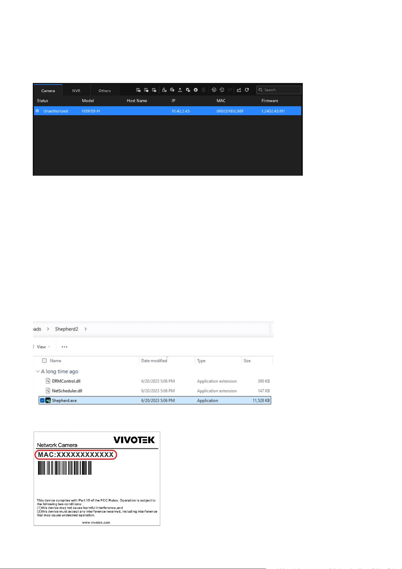
Using Shepherd to Locate and Identify Cameras on the
LAN
Shepherd is a standalone device management tool designed to simplify the installation and configuration
of multiple VIVOTEK devices. It is ideal for environments where software installation is not permitted.
Shepherd is a standalone device management tool designed to simplify the installation and configuration
of multiple VIVOTEK devices. It is ideal for environments where software installation is not permitted.
Step 1. Download and extract the Shepherd application from VIVOTEK’s official website:
https://www.vivotek.com/products/software/shepherd
Step 2. Navigate to the extracted folder and run the Shepherd application.
Step 3. Identify the camera by its MAC address, then click Add.
Step 5. To access the camera’s web interface, do one of the following:
• Enter the camera’s IP address into a supported web browser.
• Double-click the camera entry in the Device Manager interface to open it directly.
13
1 Getting Started
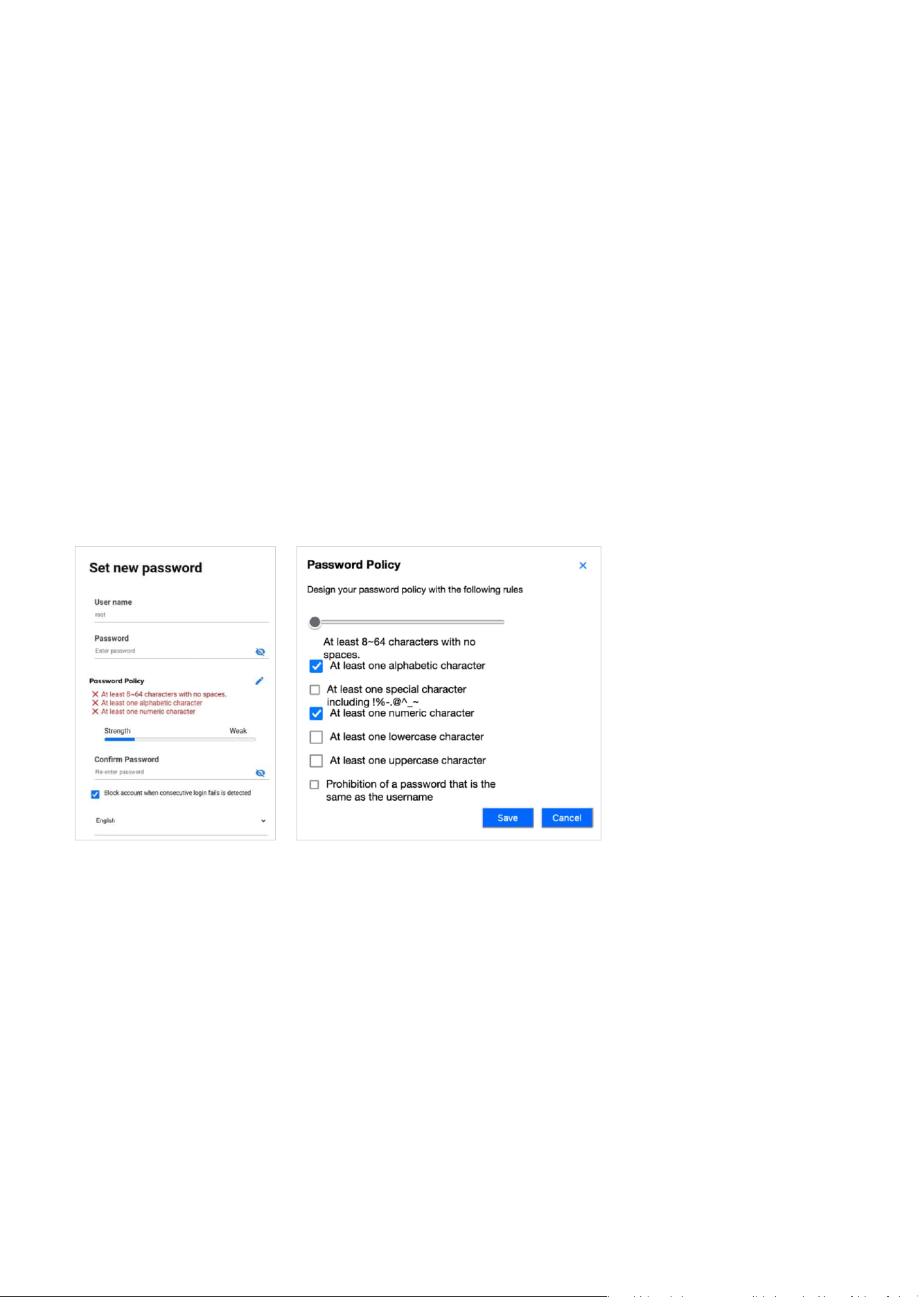
Using the Camera Web UI for First-Time Access
Set a New Password for the Root User
When users access the Camera web UI for the first time, they must set a new password for the default
root account. If necessary, they can also adjust the password policy for all users of the Camera web UI at
this point.
Step 1. Enter the new password for the root account in the "Password" field to be used as the root login
password from now on.
Note
At this point, users can click the edit icon to configure the password policy for all users when setting
passwords in the Camera web UI.
Step 2. Step 2. Re-enter the new password in the "Confirm Password" field for confirmation.
Step 3. Step 3. Confirm whether the "Block account when consecutive login failures are detected"
mechanism is enabled.
Note
By default, if the password is entered incorrectly five consecutive times within 20 seconds, the account
will be blocked for 300 seconds. User can customize the detailed settings from System > User Accounts >
Account block later.
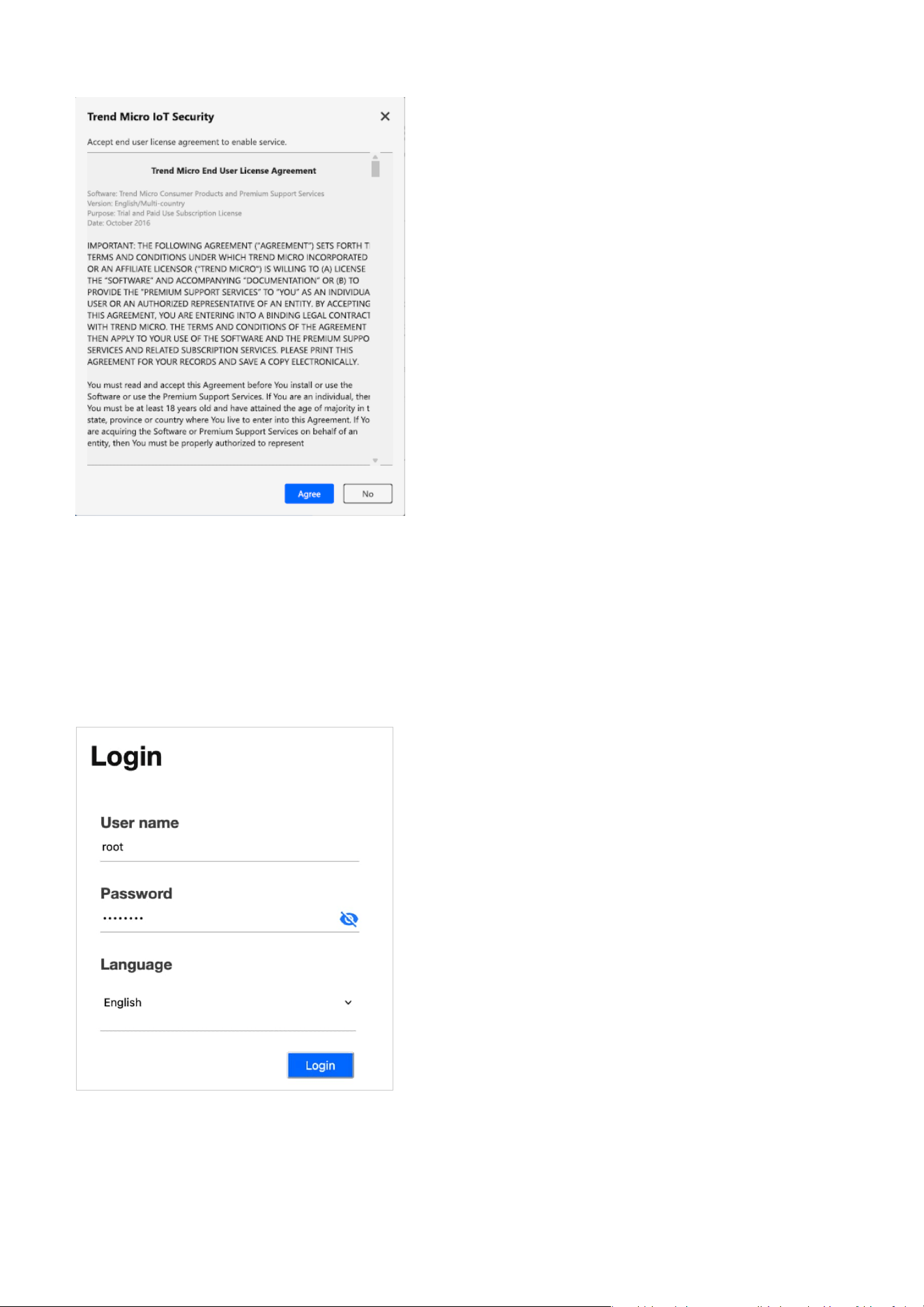
Step 4. Step 4. Set the language used in the Camera web UI.
Step 5. Step 5. Please carefully read the Trend Micro End User License Agreement and click the Agree
button.
Step 4. To access the camera’s web interface, do one of the following:
• Enter the camera’s IP address into a supported web browser.
• Double-click the camera entry in the Shepherd interface to open it directly.
14
1 Getting Started
Log In to the Camera Web UI
Step 6. Click Save button.
After setting the new password, the user can log in to the Camera web UI with the root account for first
use.
Step 1. Use root account and password to log in when accessing the Camera web UI for the first time.
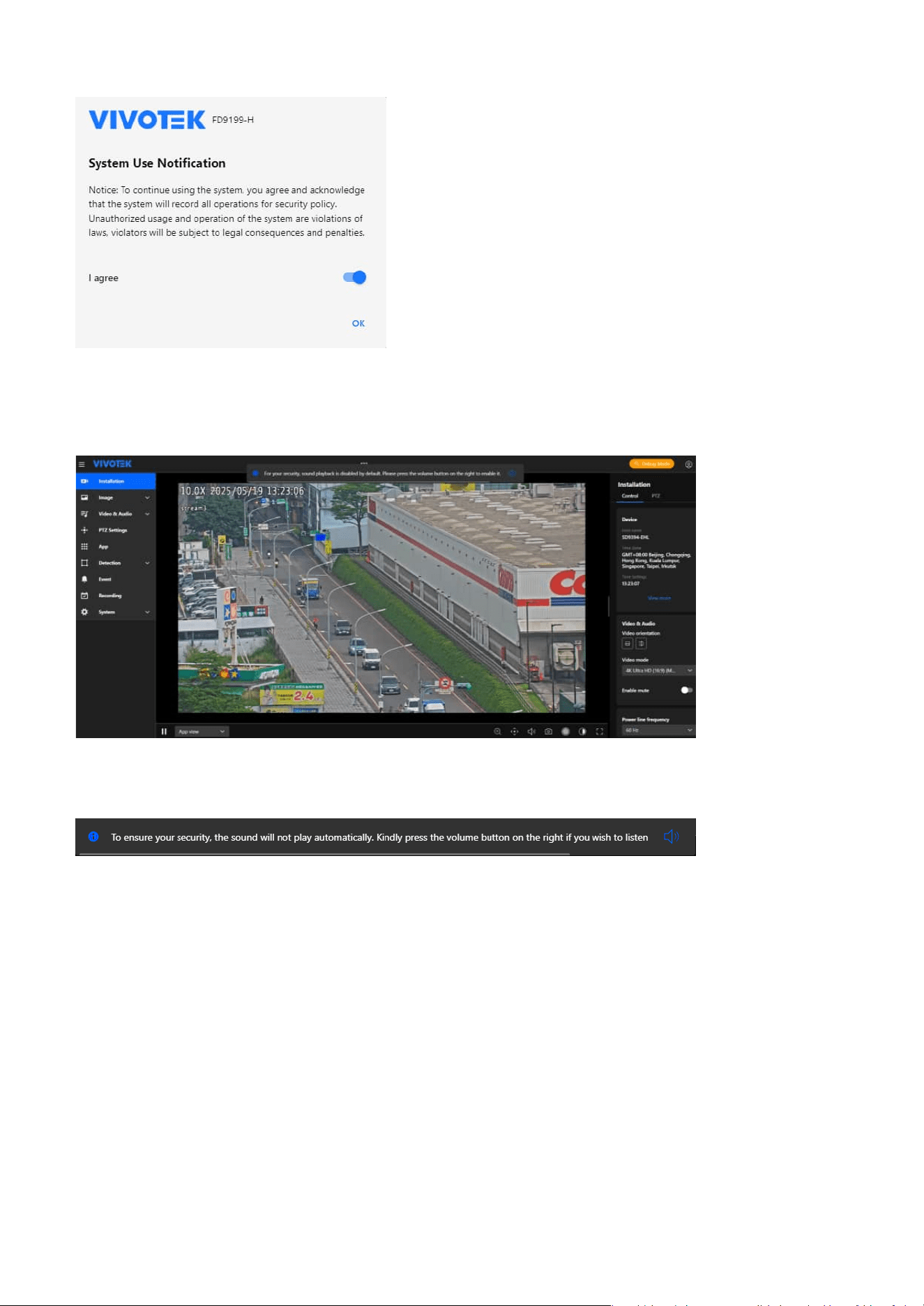
Step 2. After accessing the Camera web UI, please carefully read the System Use Notification message
and agree to its content before proceeding with the configuration and operation of the camera
through the Camera web UI.
15
1 Getting Started
Introduction to the Camera Web UI
The notification appears when a user logs into the VIVOTEK Camera WebUI with active Video Streaming,
specifically to prevent unintended audio playback without consent.
If the user takes no action, the notification will automatically disappear after 20 seconds; however, if the
user clicks the Volume button (icon) to enable audio, the notification will disappear immediately.
Note
If multiple notifications appear simultaneously (e.g., success or failure messages), these additional
notifications will be displayed below the primary message without overriding or covering this security
notification.
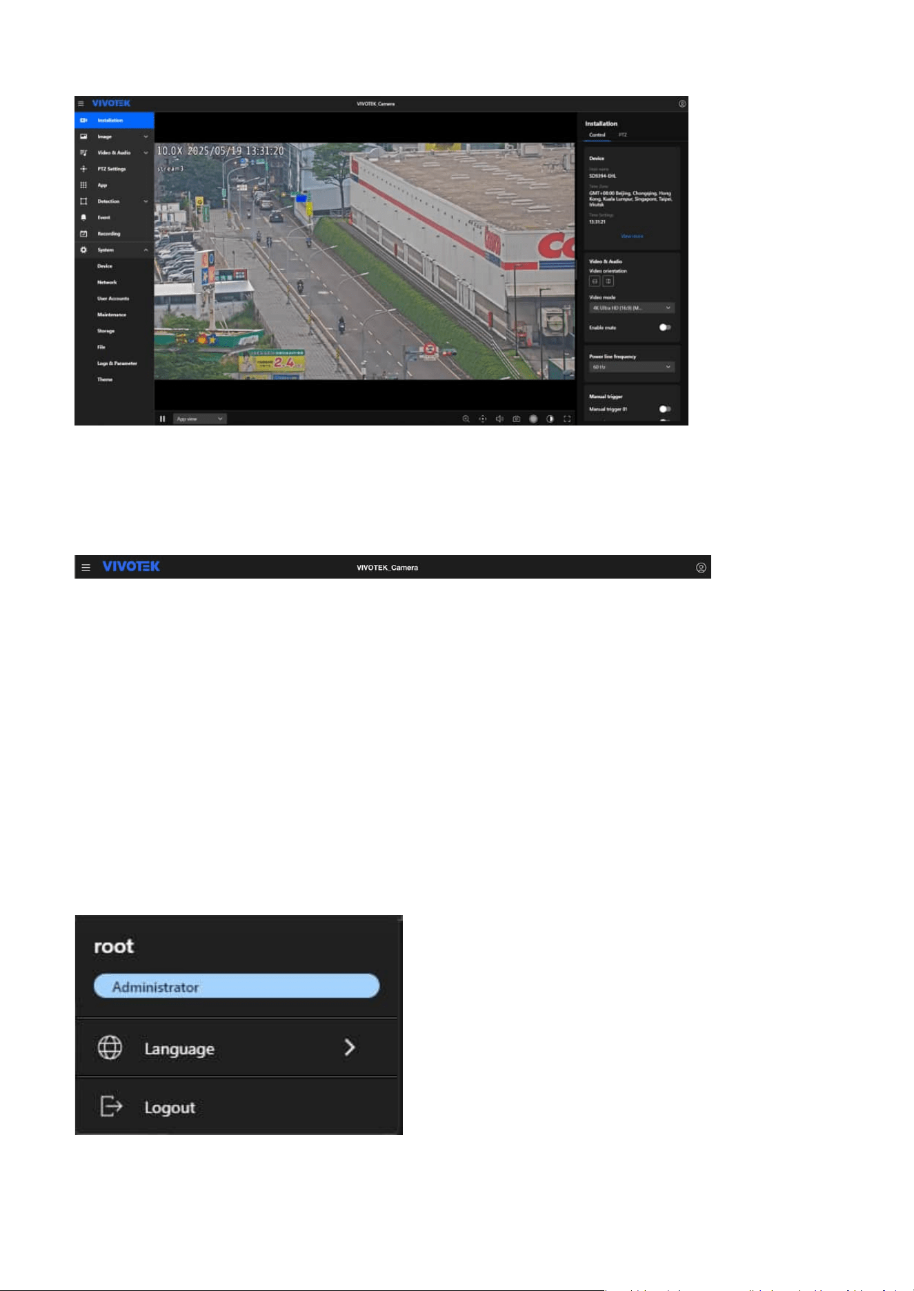
The Camera web UI screen is mainly composed of three parts: the title bar, the navigation bar, and the
content display.
Audio Playback Security Notification:
The Audio Playback Security Notification is designed to ensure the privacy and security by preventing
audio from playing automatically when entering a video streaming page.
16
1 Getting Started
The title bar
Primarily serves as the title display for the Camera web UI, allowing users to quickly identify it. The
functions are arranged from left to right as follows.
Menu expansion/collapse button
Allows control over menu expansion or collapse to maximize the display of image content or settings
interface, providing a better experience for users when operating the camera.
Logo
By clicking the VIVOTEK logo, users can quickly access the VIVOTEK official website for more product
information. Users can also customize the logo and link displayed in System > Theme > Logo.
Host name
The Camera web UI displays the model name as the default host name. Users can go to System > Device
> Information to modify the name to something more identifiable.
Account information
Users can view the current login account information and the associated role permissions here. They can
also adjust the system language to their preference at any time.
17
1 Getting Started
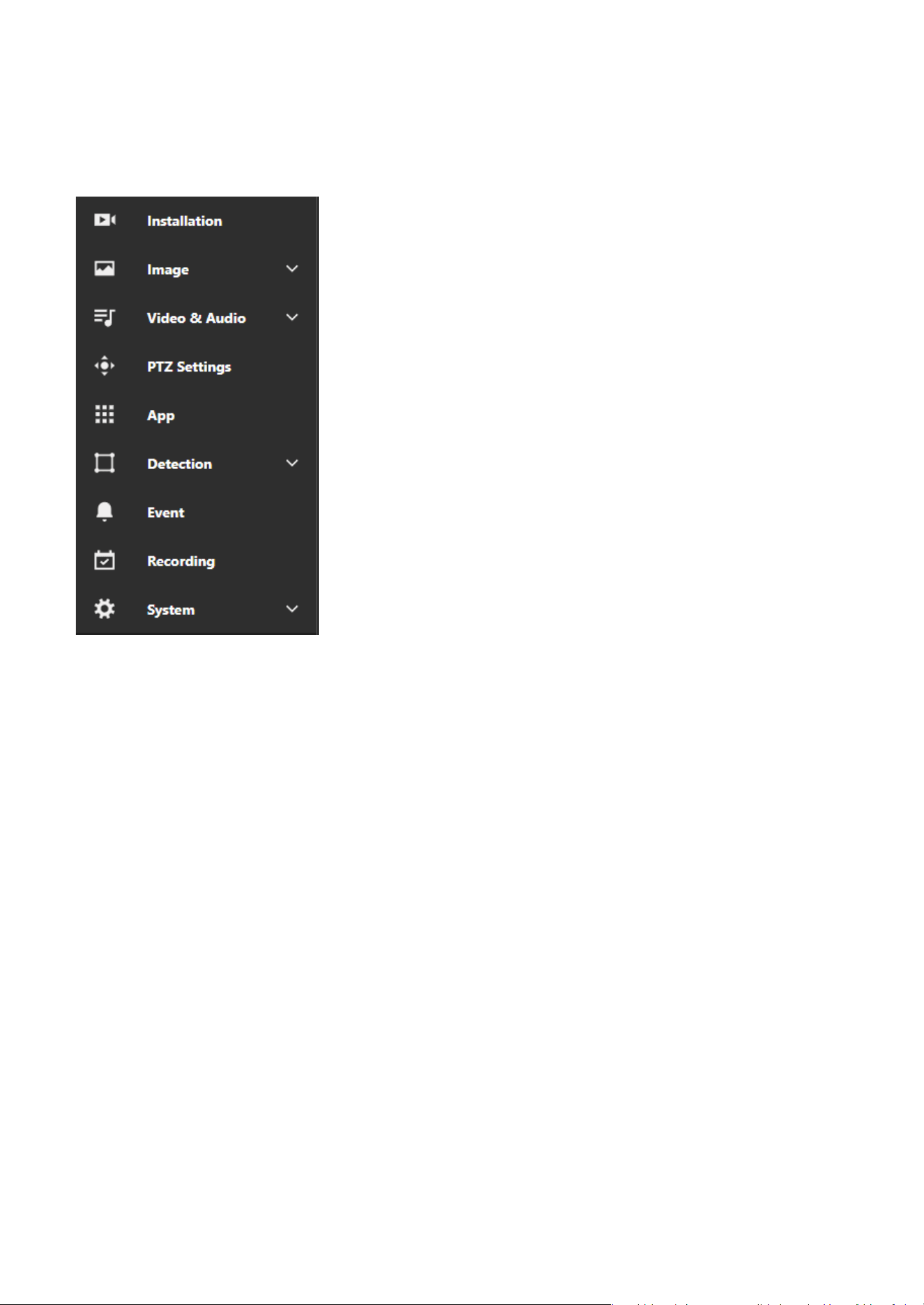
The navigation bar
Functions and settings within the Camera web UI are centrally categorized to help users quickly locate the
desired configuration items.
Installation
The Installation section helps users set up and fine-tune the camera by providing options for positioning,
focus, and initial configuration to ensure proper alignment and operation.
Image
The Image section allows users to adjust image quality and appearance, including settings for brightness,
contrast, saturation, sharpness, exposure, white balance, and orientation to ensure optimal video output.
Video & Audio
The Video & Audio section allows users to configure video settings such as resolution, bitrate, frame
rate, and codecs, as well as manage audio options, including enabling recording, selecting codecs, and
configuring microphone or speaker settings.
PTZ Settings
The PTZ Settings section allows users to manage pan, tilt, and zoom functions by configuring movement
speed, preset positions, and patrol patterns for precise and smooth camera control.
App
The App section allows users to manage VIVOTEK-specific applications or plugins, using these applications
to expand the camera's functionality.
Detection
The Detection section leverages intelligent detection technologies to provide comprehensive monitoring
capabilities, including Smart VCA features such as line crossing, intrusion, as well as Motion Detection,
Audio Detection, Shock Detection, and Tampering Detection. Users can configure detection zones,
sensitivity, and event triggers to ensure accurate, intelligent monitoring and enhanced security for various
scenarios.
18
1 Getting Started
The content display
This area serves as the main workspace of the Camera web UI, where the layout and content change
based on the different categories selected on the navigation bar. The following operational instructions in
this document will focus primarily on this section.
Event
The Event section allows users to define event triggers and conditions, configuring actions such as
sending notifications, recording video, or activating alarms to respond effectively to specific events.
Recording
The Recording section allows users to configure recording modes, such as continuous, event-based, or
scheduled recording, and set storage locations like SD cards or network storage to manage video footage
efficiently.
System
The System section provides tools for managing device settings, network configurations, user accounts,
maintenance tasks, storage options, logs, and interface customization to ensure optimal performance,
security, and usability of the camera.
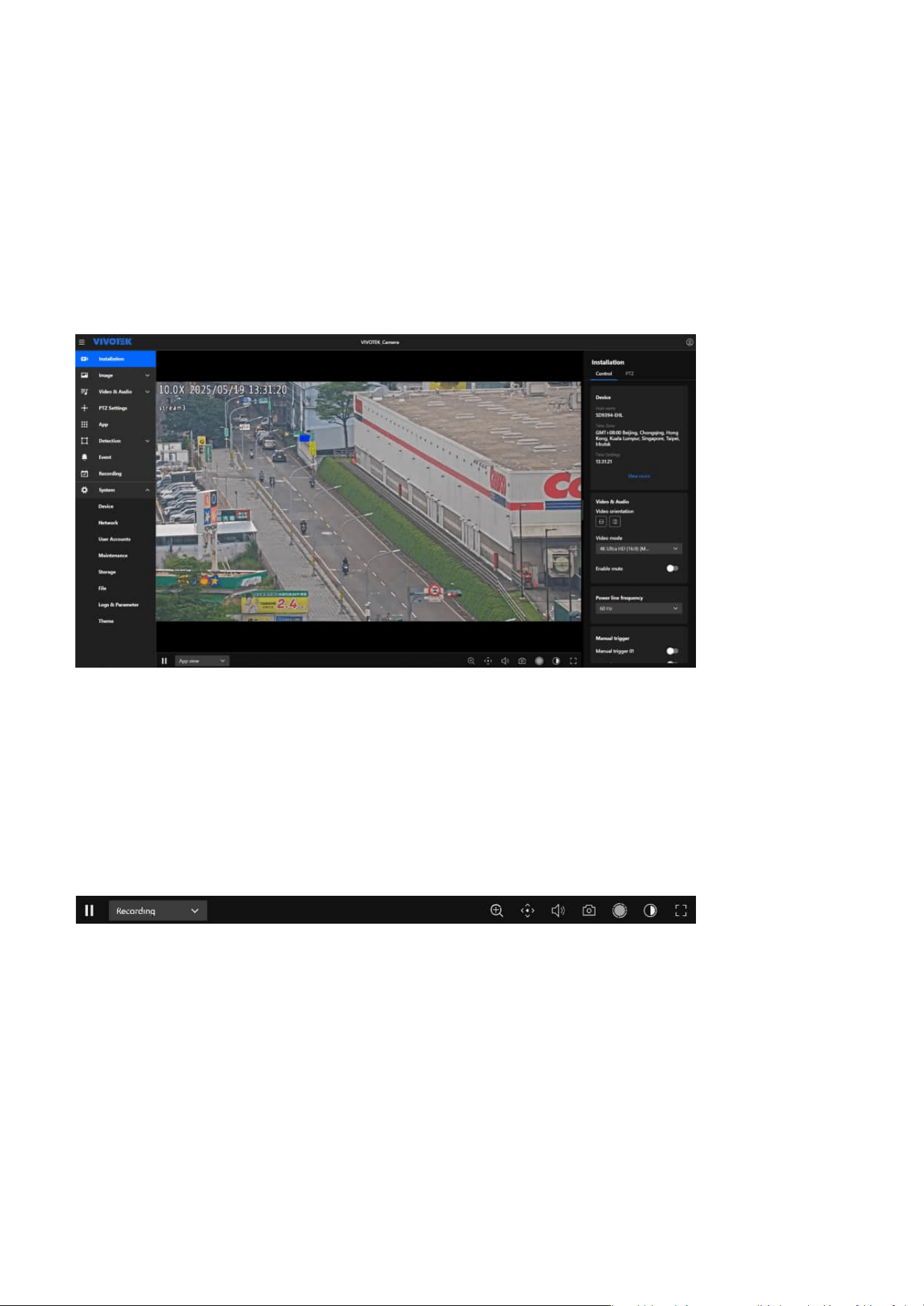
19
Installation
2
Navigating the Video Stream Toolbar for Enhanced
Control
The Video Stream Toolbar is located at the bottom of the Camera Web UI, providing users with various
features that can be used in real time during video streaming. The functions are arranged from left to
right as follows.
This category serves as the first screen upon entering the Camera Web UI. Its primary purpose is to assist
users in quickly and conveniently setting up the desired monitoring view under the Installation category
after installing the camera.
Pause/Play Button
When users want to view or confirm the details presented in the video streaming image, they can press
the Pause button at any time to pause the image. Pressing Play button again will resume the video
streaming playback.
Media Profile Menu
Users can quickly switch between the three different media profiles—Recording, Live View, and App
View—based on different situational needs, reducing the time required for video settings. Users can also
add or modify media profiles in Video & Audio > Media Profile.
Picture In Picture
The “Picture In Picture” feature allows users to magnify a specific area of the image for closer inspection.
20
2 Installation
After clicking the “Picture In Picture” icon (magnifying glass), a small preview window appears in the
bottom-right corner. Users can drag the selected area within this window to move the zoomed-in view,
making it easier to examine fine details such as faces, objects, or text. While this feature does not change
the camera’s actual focal length, it offers a convenient way to focus on important areas and enhance
monitoring efficiency. The feature is only available when the resolution is set to 1080p or higher; adjust
the resolution setting if necessary.
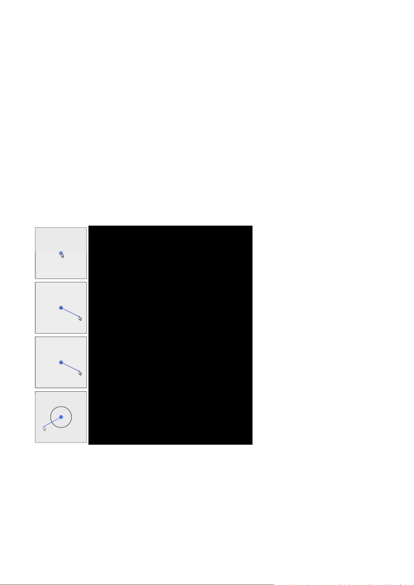
PTZ Control Mode
The PTZ Control Mode provides precise pan, tilt, and zoom (PTZ) control, enhancing surveillance efficiency
and flexibility.
• Joystick:
Allows users to manually control PTZ movement by dragging the mouse, simulating a joystick-like
experience.
Operation:
• Click and hold the left mouse button, then drag in the desired direction to move the camera.
• The speed and direction are controlled by the dragging motion, allowing smooth, continuous
monitoring.
• Click on Image:
Users can click anywhere within the image to automatically center the camera on the selected location.
Operation:
• Click on a specific area. The camera will adjust its angle to focus on that point.
• This function helps quickly shift focus without manually adjusting PTZ controls.
• Area Zoom:
Allows users to click on a specific area to move the camera and zoom in for a clearer view.
21
2 Installation
Efficiently Adjust Camera Settings via the Installation
Panel
The Installation panel provides commonly used and essential information, along with quickly adjustable
settings, to help users complete the camera installation and setup more efficiently and conveniently.
Additionally, the adjusted settings are instantly reflected on the video streaming display.
Volume
Users can adjust the volume of the video streaming according to their needs.
Snapshot
Users can capture images from video streaming at any time.
Start Emergency Recording
The feature enables users to capture live video footage on demand without relying on scheduled or
event-triggered recording.
Color
Users can switch the video streaming display to Color or Black & White mode according to the current
scenario, such as daytime or nighttime.
Full Screen
Users can display the video streaming image in full-screen mode.
Operation:
• Click on a target area. The camera will zoom in to enhance detail visibility.
22
2 Installation
Flip Vertically reflect the display of the live video.
Mirror Horizontally reflect the display of the live video.
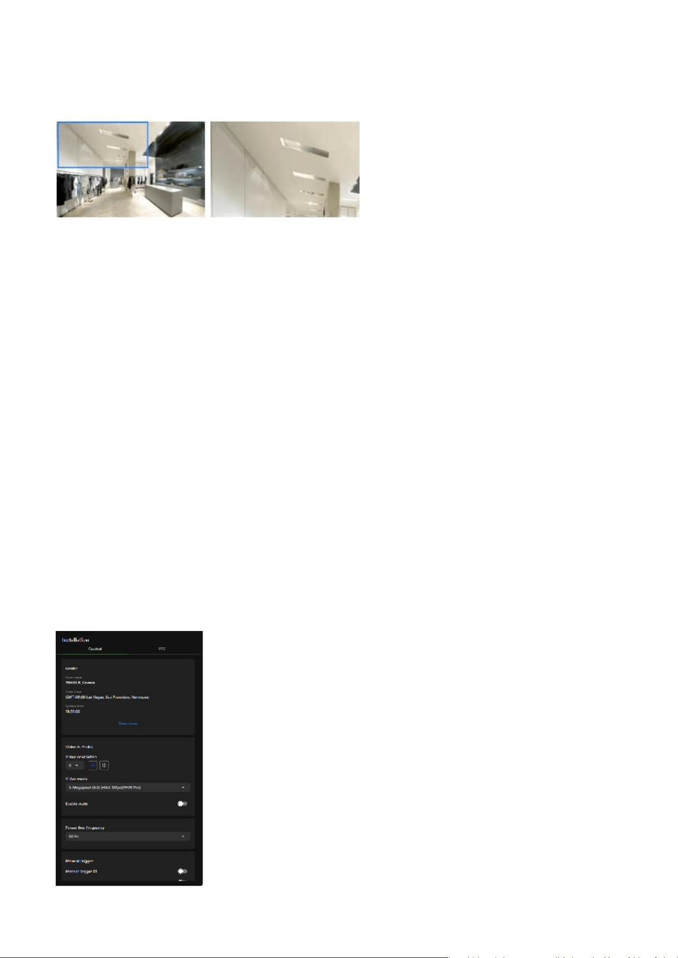
Control panel
Video & Audio:
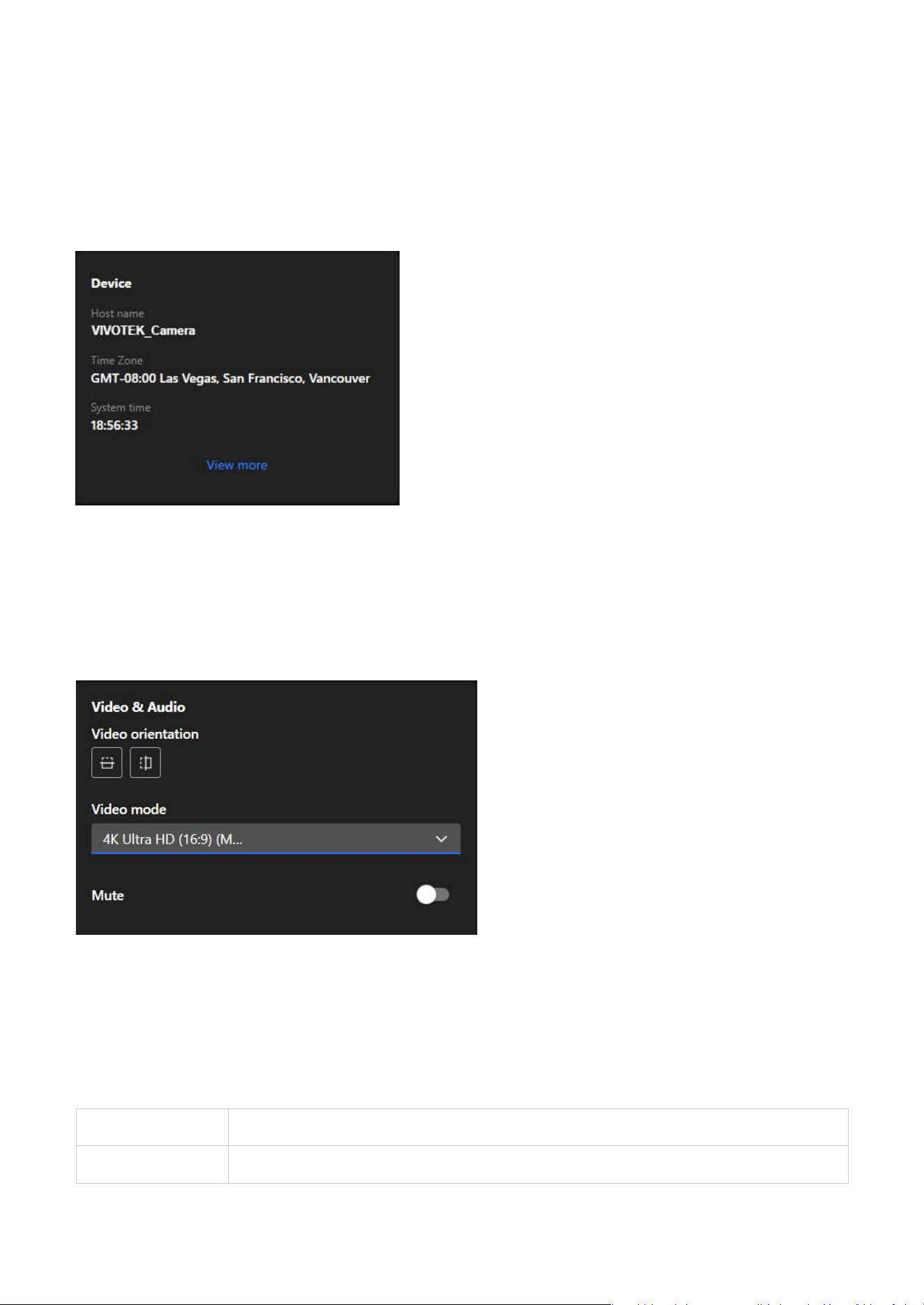
Device:
The Device card serves as a quick reference for critical device information, helping users verify the
camera’s identity, time zone, and system time are correctly configured for seamless operation and event
tracking. Additionally, clicking "View More" will navigate to System > Device > Information for further
adjustments.
Video orientation
The camera may be installed on a vertical, side-facing, or tilted surface to accommodate the interior or
exterior design of a building. The interior of a building may be shaped as a narrow rectangular space, such
as a corridor. A conventional HD image, such as one with a 16:9 aspect ratio, may be incongruous due to
its wide horizontal view. With video rotation, the camera can more effectively cover the field of view in a
tall and narrow scene.
Essential settings and functions required during the camera installation process are integrated into the
Control Panel allowing users to view the desired display effects while installing the camera.
23
2 Installation
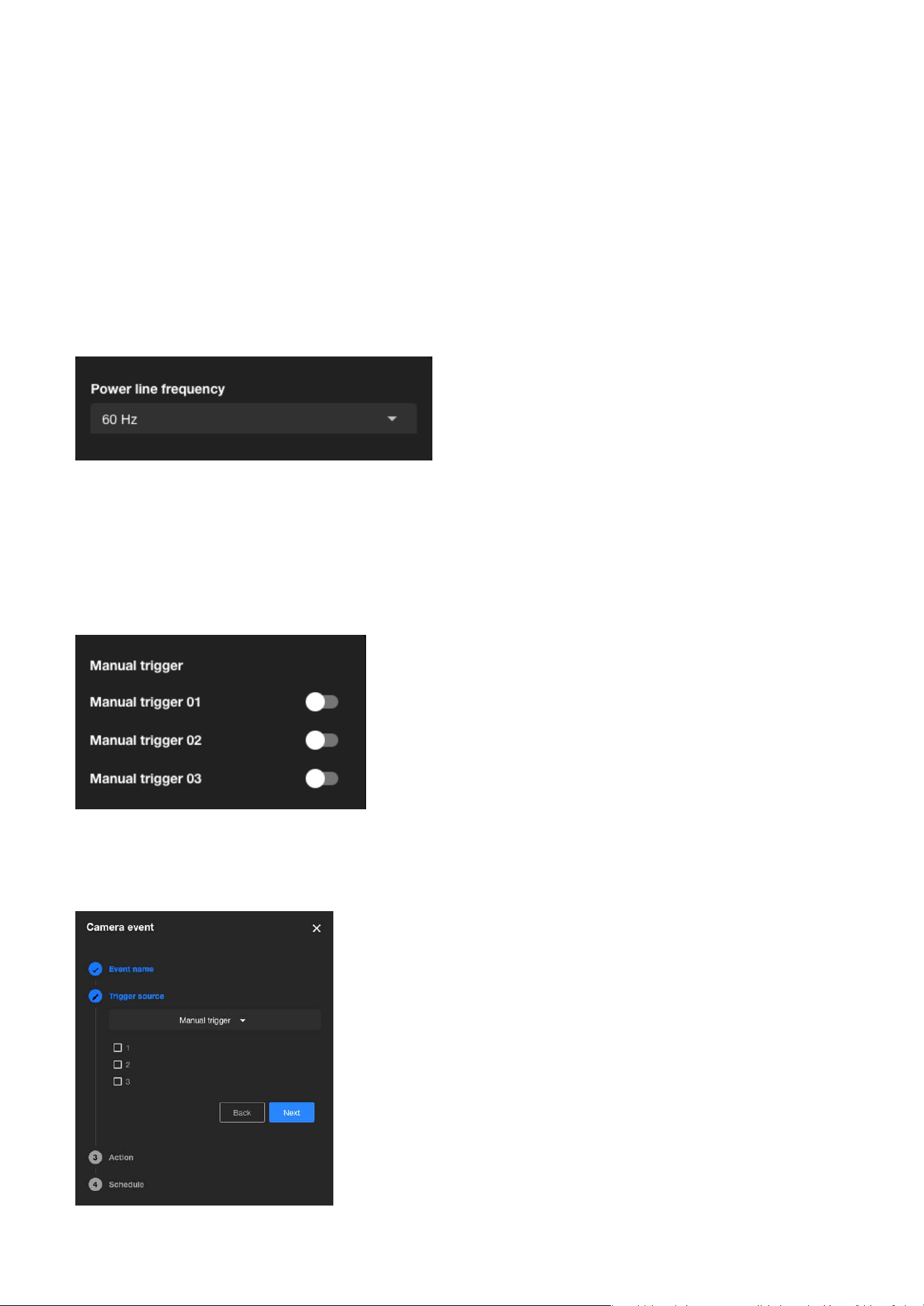
Power line frequency:
Manual trigger:
The Power line frequency setting ensures stable video quality by allowing users to align the camera's
frequency with the local power grid, effectively preventing flicker in areas with fluorescent or artificial
lighting; selecting the correct frequency, such as 60 Hz for North America or 50 Hz for many European
and Asian countries, helps eliminate video flicker caused by power line interference.
Allows users to manually enable event triggers by toggling the on/off switch on the Installation panel.
Before using this function, ensure that events are assigned to Manual Trigger 01 to 03 under the
Event
category.
Video mode
Refers to the image processing modes used by IP cameras during video recording and transmission. These
modes are adjusted based on monitoring environments, network bandwidth, storage requirements,
and application scenarios to enhance image clarity and smoothness, achieving optimal performance and
efficiency under various network conditions.
Mute
Provides the option to enable or disable audio recording, where toggling it on mutes the camera audio to
prevent any audio capture.
24
2 Installation
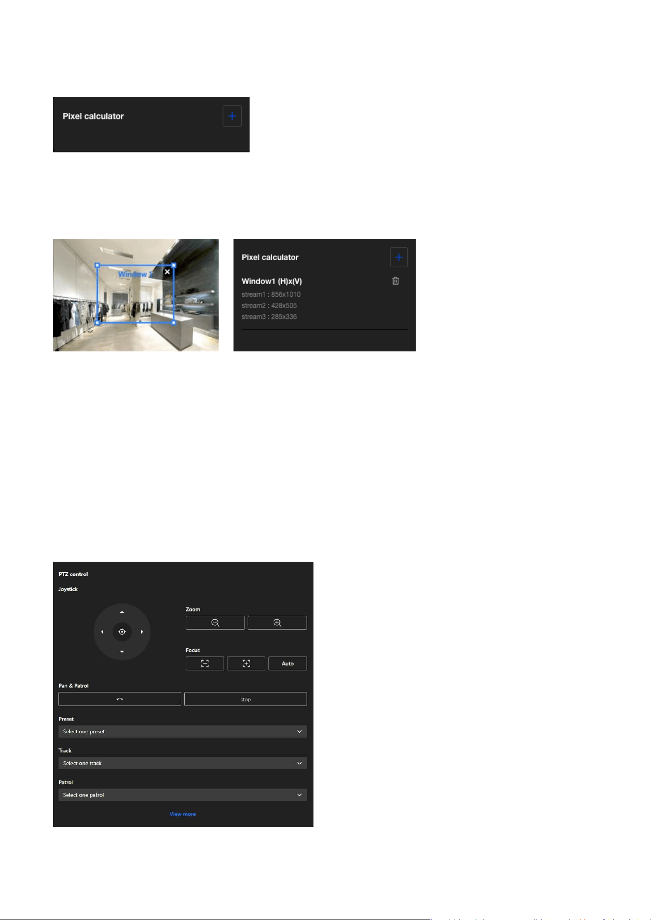
PTZ panel
PTZ control
Pixel calculator:
Click the "Add window " button to create a pixel calculator window. Move your cursor over the window
to position it in the area of interest and adjust the window size to fit the area. Once the window is
configured, the pixel count on its edges will be displayed, assisting you in assessing whether the current
configuration meets the requirements.
Using this visual tool, you can estimate the coverage area, the distance to the target, and place a ruler
or an object of known size. Then, you can draw a calculator frame to cover the subject of interest. The
calculated values will be listed at the bottom of the screen, helping you determine whether the current
settings meet the pixel count requirements.
The PTZ panel provides users with a convenient way to adjust the monitored image position by operating
the pan, tilt, and zoom functions, and quickly switch between preset positions to monitor key areas.
25
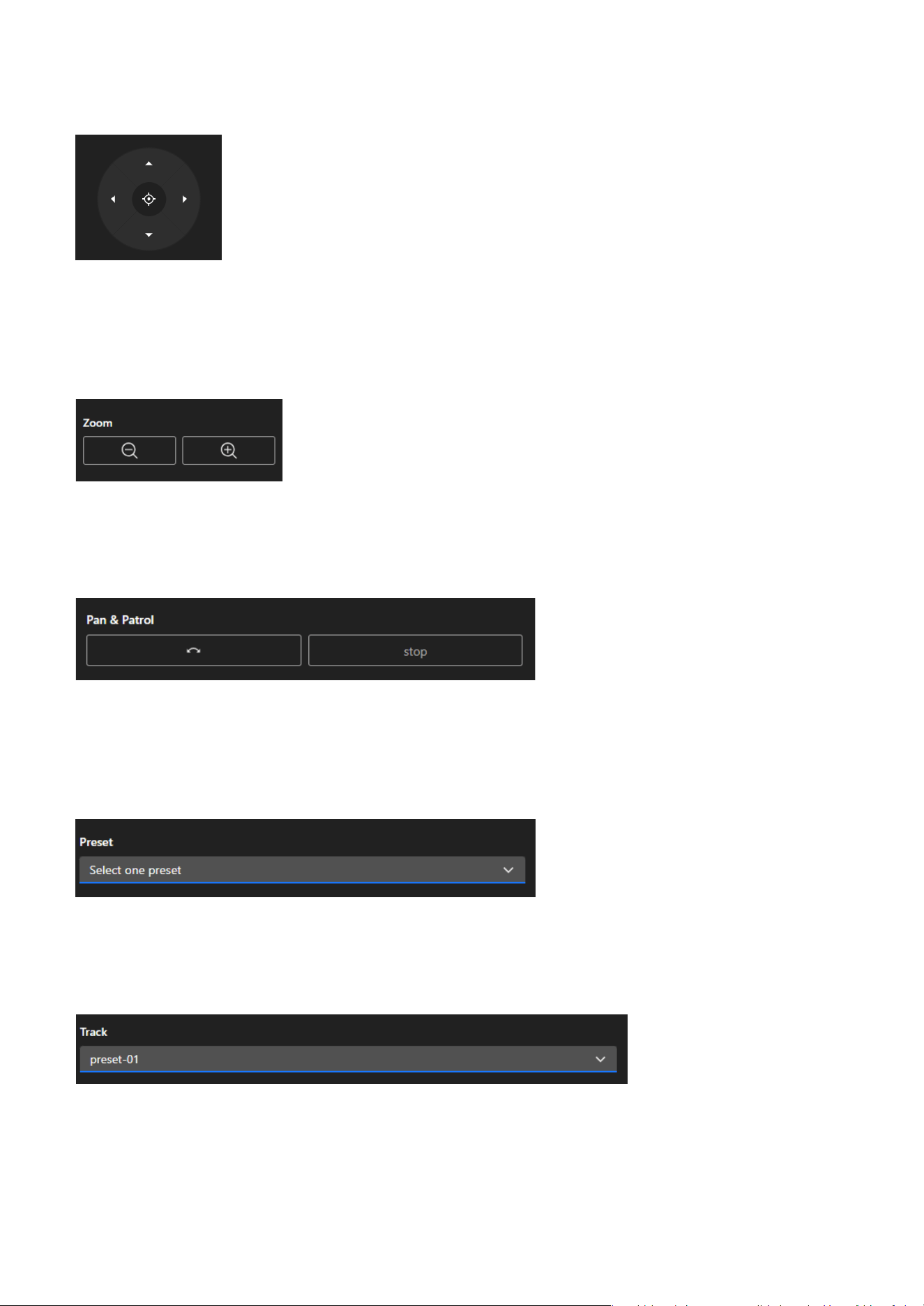
2 Installation
Users can move the monitored area’s image by operating the joystick, adjusting the view to the desired
monitoring area. Additionally, pressing the Home button will restore the view to the preset Home
position. Users can set the position represented by Home in
PTZ Settings > Home & Preset.
Users can use the Zoom button to freely zoom in or out on the current monitoring screen to an
appropriate size.
When the user clicks the Pan button, the monitoring screen will move left and right, centering on the
current view, to expand the surveillance range. Click Stop button to halt the current monitoring screen's
Pan or Patrol.
Users can quickly switch the current monitoring perspective by selecting a screen set as a Preset. Users
can configure the Preset positions on the
PTZ Settings > Home & Preset page.
Joystick
Zoom
Pan & Patrol
Preset
Track
The Track feature allows users to initiate auto-tracking from a specified preset point. Click the dropdown
menu to select a preset; the camera will move to the selected position and begin tracking based on
the configured detection rules. For example, if an intrusion detection rule is enabled, the camera will
automatically track when the rule is triggered. The tracking target depends on the detection type

26
2 Installation
The Patrol feature allows users to initiate a predefined patrol route consisting of multiple preset points.
Click the dropdown menu to select a patrol route; the camera will automatically move between the preset
positions based on the sequence and dwell times defined by the user. Patrol routes must be configured
in PTZ Settings > Patrol before they appear in the list. This feature is useful for continuously monitoring
multiple key areas without manual control.
configured by the user. This feature enables responsive, rule-based surveillance by combining preset
navigation with intelligent object tracking.
Patrol
27
Image
3
Optimizing Image Quality with VIVOTEK Camera Settings
General
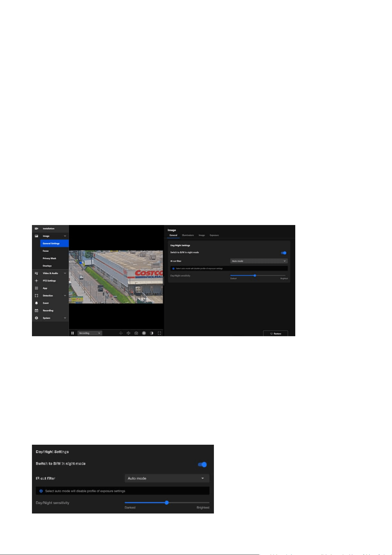
Day/Night Settings
The Image provides various image adjustment options, including General Settings, Privacy Mask, and
Overlays, to meet the needs of different scenarios. These settings can enhance image performance,
protect privacy, and add supplementary information.
The General Settings for images are typically used to adjust and optimize the parameters of cameras or
imaging systems to ensure that the generated images meet the required specifications. These settings
can be divided into four main categories: General, Illuminators, Image, and Exposure. Below is a brief
introduction to each category.
The General page provides users with core features to adjust image quality, ensuring optimal camera
performance in various environments.
The purpose of the Day/Night Settings is to enhance the imaging quality of cameras under different
lighting conditions.

28
3 Image
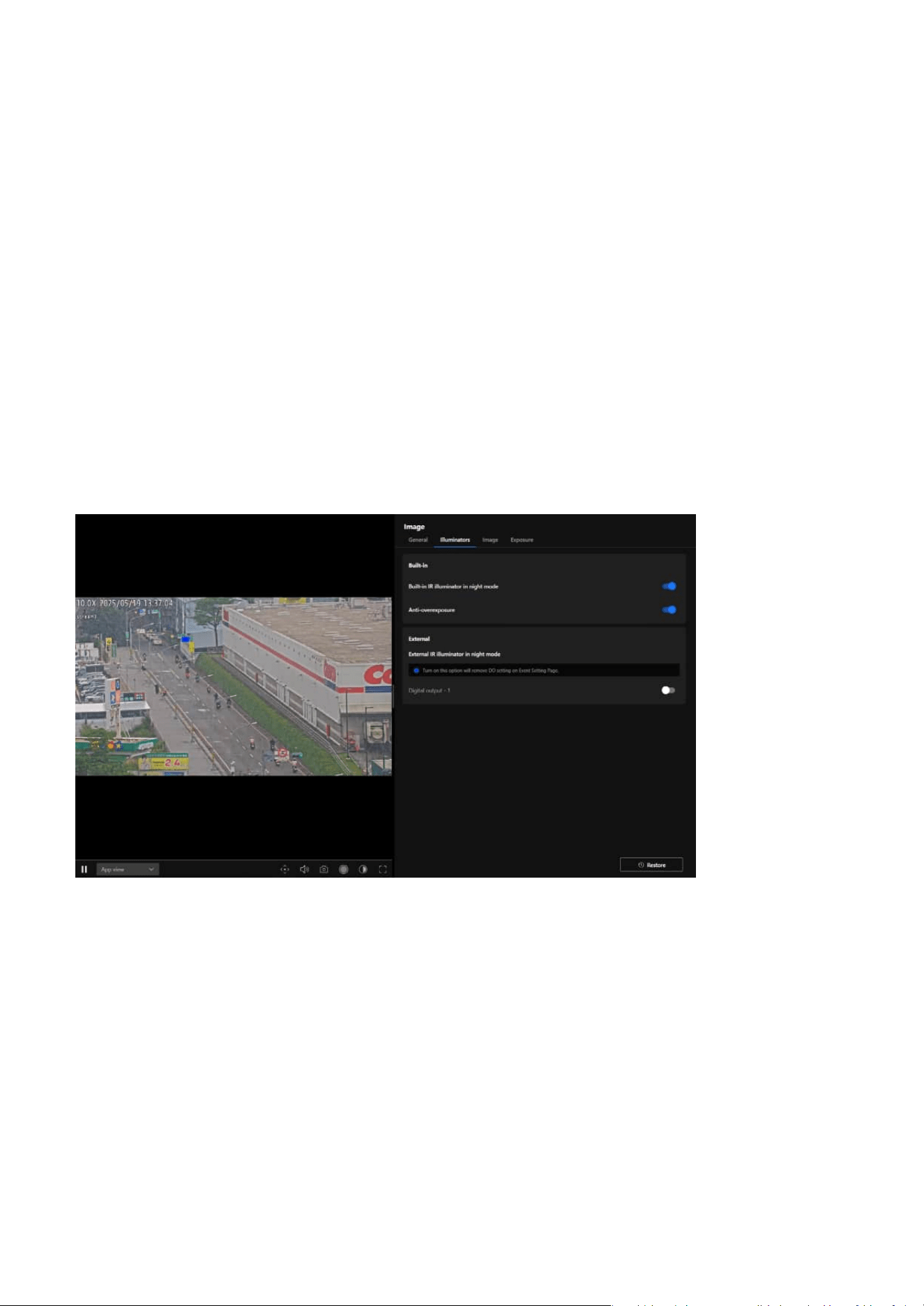
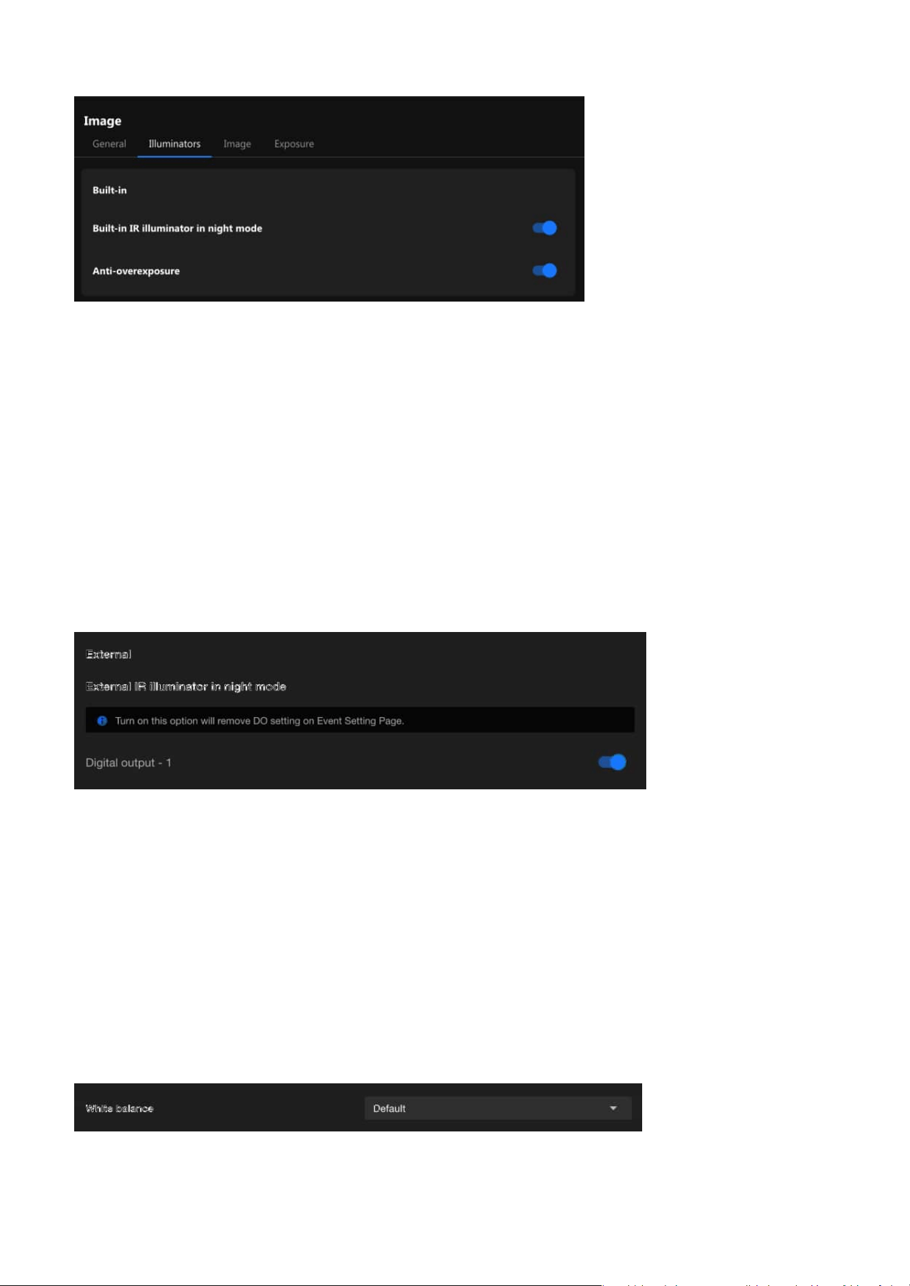
Illuminators
Built-in
The "Illuminators" page refers to the settings related to the infrared (IR) illuminator. In low-light or
completely dark environments, these IR illuminators automatically activate to provide the necessary
lighting, enabling the camera to capture clear images. This feature is particularly suitable for scenarios
requiring surveillance at night or in low-light conditions.
VIVOTEK's network cameras are equipped with built-in infrared (IR) illuminators designed to enhance
image quality in nighttime or low-light environments. These built-in IR illuminators provide uniform
lighting, ensuring clear images even in panoramic views.
Switch to B/W in night mode
After enabling this feature, the camera will automatically switch to black-and-white display in night mode.
This design aims to enhance image clarity and contrast in low-light conditions, ensuring clear surveillance
footage even in insufficient lighting.
IR cut filter
The IR cut filter is a removable filter that blocks infrared light from entering the image sensor during the
day to prevent color distortion in images. In night mode, the camera automatically removes this filter,
allowing infrared light to enter the image sensor. This works with built-in or external infrared illumination
to enhance image sensitivity in low-light or no-light conditions, providing clearer night surveillance
footage. The available modes for the IR cut filter are as follows:
• Auto mode (Select auto mode will disable profile of exposure settings)
The Network Camera automatically removes the filter by judging the level of ambient light.
• Day mode
In day mode, the IR-cut filter is placed in front of the sensor to block infrared light, ensuring accurate
color reproduction.
• Night mode
In night mode, the IR cut filter is removed from the optical path to allow infrared light to reach the
sensor for improved visibility in dark environments.
• Synchronize with digital input
If an external IR device with its own light sensor is connected, a digital input from the device can be used
to trigger the IR cut filter. This allows synchronization of light level detection between the camera and
the external IR device.
• Schedule mode
The Network Camera switches between day mode and night mode based on a specified schedule. Enter
the start and end time for day mode. Note that the time format is [hh:mm] and is expressed in 24-hour
clock time. By default, the start and end time of day mode are set to 07:00 and 18:00.
Day/Night sensitivity
Adjust the IR cut filter's sensitivity to lighting conditions from the Darkest to the Brightest.
29
3 Image
Image
White balance
External
When External IR Illuminator in Night Mode is enabled, the camera will activate the external IR illuminator
through Digital Output. External IR illuminators typically offer higher brightness or a wider illumination
range, making them ideal for scenarios that require enhanced surveillance performance in low-light
environments.
The Image page in the Camera web UI allow users to adjust various parameters to optimize image quality
for different environments and applications.
Built-in IR illuminator in night mode
• Utilizes infrared light for discreet surveillance, suitable for completely dark environments or situations
requiring non-intrusive monitoring.
• Maintains the privacy of monitored areas while ensuring stable image clarity.
Anti-overexposure
Enabling the Anti-Overexposure feature ensures balanced image quality by dynamically adjusting to
challenging lighting conditions, preventing overly bright areas from affecting visibility or detail capture in
surveillance footage.
NOTE
Only SD9394 model supports built-in IR illuminators.
The White Balance setting in VIVOTEK cameras is essential for ensuring that the colors in captured video
appear natural and accurate under varying lighting conditions. This feature provides multiple modes to
30
3 Image
Default
• In this mode, the camera automatically adjusts the white balance based on the lighting
conditions.
•
It is suitable for environments with changing light sources, such as outdoor areas where sunlight
and shade vary throughout the day.
•
The camera continuously evaluates the scene and dynamically adapts to ensure accurate color
representation.
Fixed current
• This mode locks the white balance to the current automatic setting at the moment it is activated.
•
It is useful in environments with consistent lighting, where maintaining a stable white balance is
more important than adapting to changes.
•
For example, this mode is ideal for spaces with fixed artificial lighting, such as offices or
warehouses.
Manual
• This mode allows users to manually set the white balance by adjusting specific parameters like
RGain(red) and BGain(blue) levels.
•
It offers the most control and is ideal for scenarios with specialized lighting, such as theatrical
productions, where precise color adjustments are required.
•
Users can customize the settings to suit their specific needs and ensure color accuracy in unique
lighting conditions.
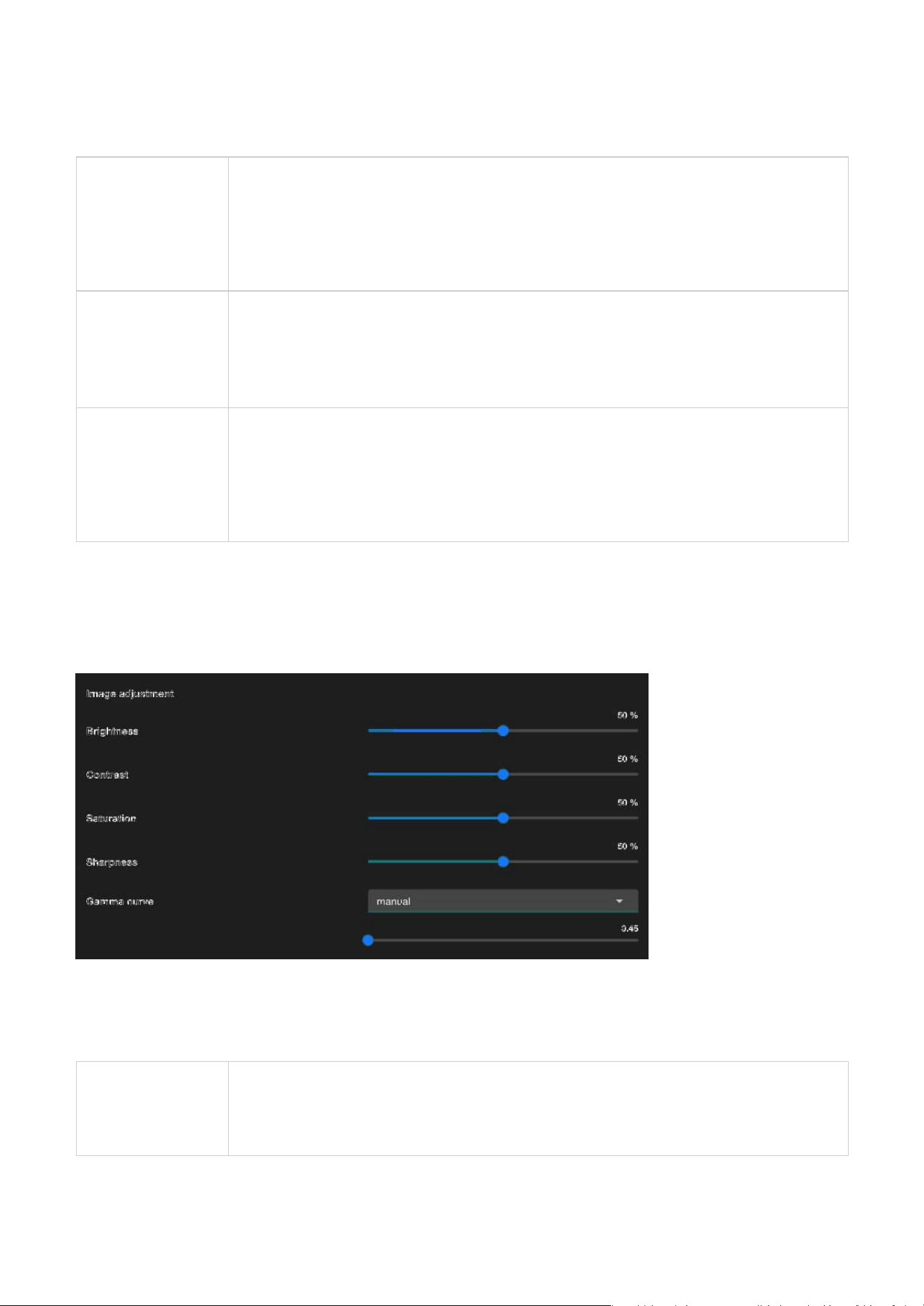
Image adjustment
accommodate different environments and use cases, allowing users to achieve optimal color accuracy
and image quality.
By selecting the appropriate white balance mode, users can optimize the performance of their VIVOTEK
cameras for a variety of environments and use cases.
Image Adjustment is essential for fine-tuning the visual quality of the captured images. These adjustments
allow users to customize the appearance of the footage to meet their specific needs or adapt to different
environmental conditions.
Brightness
• Brightness controls the overall lightness or darkness of the image. Increasing brightness makes
the entire image appear lighter, while decreasing it makes the image darker.
• Adjust the brightness to ensure clear visibility in varying light conditions, such as low-light
environments or overexposed areas.
31
3 Image
Contrast
• Contrast determines the difference between the lightest and darkest parts of the image. Higher
contrast makes shadows darker and highlights brighter, enhancing the distinction between
objects. Lower contrast results in a flatter, less dynamic image.
•
Use contrast to improve image clarity by enhancing the differentiation between objects in the
scene.
Saturation
• Saturation controls the intensity of colors in the image. Increasing saturation makes colors more
vivid and vibrant, while reducing it leads to a more muted or grayscale appearance.
•
Adjust saturation to balance the color intensity for optimal image appearance, especially in
scenes with overly vivid or dull colors.
Sharpness
• Sharpness determines how clearly the details and edges of objects are defined in the image.
Higher sharpness enhances the clarity of edges, but excessive sharpness can cause unnatural
outlines or noise.
•
Modify sharpness to emphasize details without introducing artifacts, particularly in scenes
requiring precise identification, like license plates or facial features.
Gamma Curve
• The gamma curve defines the tonal response of the camera, affecting how brightness levels are
distributed. Adjusting gamma alters the mid-tones of the image without significantly affecting
the darkest or brightest areas.
•
Use gamma correction to optimize image brightness and contrast for better visual
representation under challenging lighting conditions.
*This option is disabled when the WDR feature is enabled.
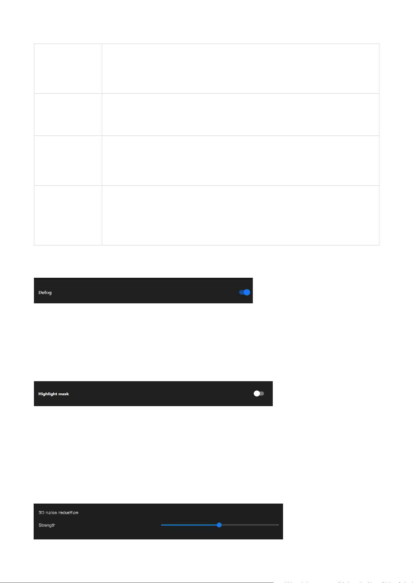
Defog
Highlight mask
3D noise reduction
Defog is designed to enhance image clarity in foggy, hazy, or smoggy conditions. It works by adjusting the
image's contrast and visibility to reduce the effects of atmospheric conditions that obscure details. This
feature is particularly useful in outdoor surveillance environments, ensuring better object recognition and
scene visibility despite challenging weather conditions.
Highlight Mask in VIVOTEK cameras is a feature that detects and marks overexposed areas in the image.
It helps users identify regions where excessive brightness may cause detail loss, ensuring better image
clarity. By visually highlighting these areas, users can adjust exposure settings such as shutter speed, gain,
or iris control to optimize image quality. This feature is especially useful in high-contrast environments like
outdoor surveillance, parking lots, or entrances, preventing overexposure and preserving critical details
in the monitored scene.
32
3 Image
Integrate image-related settings into a profile
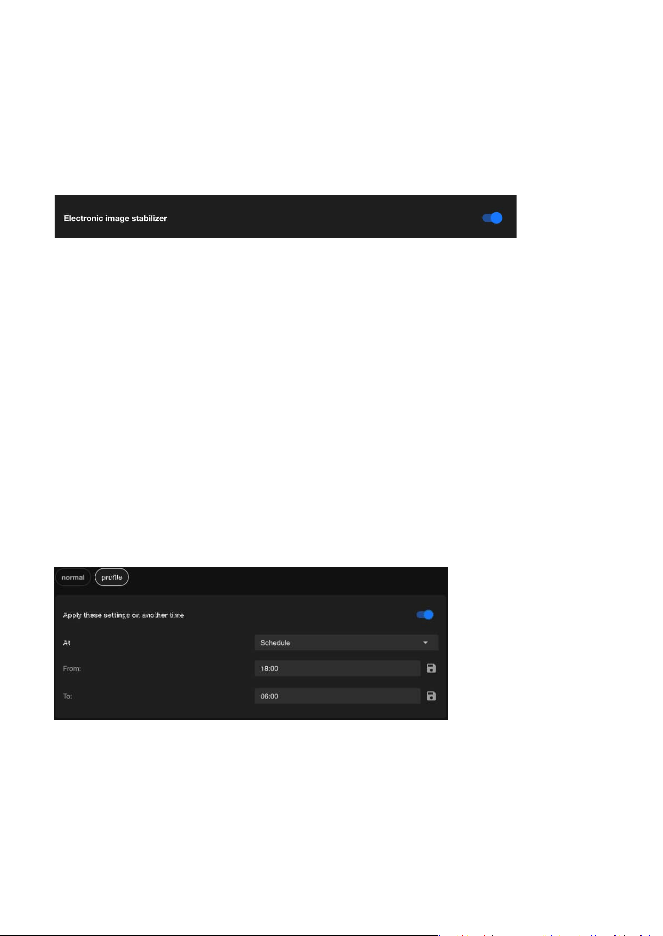
Electronic image stabilizer
Electronic Image Stabilizer (EIS) function is designed to reduce image jitter caused by external factors,
such as wind, vibrations, or cameras mounted on unstable structures. This feature stabilizes and
smoothens the footage by adjusting the image output through software algorithms. When enabled,
EIS reduces the field of view by about 25%. However, the increased stability significantly enhances the
viewing experience, especially at higher zoom levels. Despite the reduced FOV, EIS provides significant
advantages that contribute to overall video performance:
• Improves video quality:
EIS reduces blurriness and jitter caused by vibrations, delivering smoother and clearer video footage.
• Enhances critical detail readability:
By stabilizing the image, it becomes easier to identify important details such as license plates, faces, and
objects.
• Optimizes video analytics performance:
Stability helps reduce false detections, improving the accuracy of analytic features like motion detection
and object recognition.
These advantages make EIS an essential feature for maintaining reliable surveillance, especially in
environments subject to unavoidable vibrations or movement.
3D noise reduction is primarily used in low-light environments to reduce noise and flicker in the image.
You can use the slider to adjust the noise reduction strength. Please note that enabling this feature on the
video channel will consume system computing resources. However, when this feature is set to a higher
strength under low-light conditions with fast-moving objects, afterimage trails may occur. In such cases,
you may choose to lower the strength.
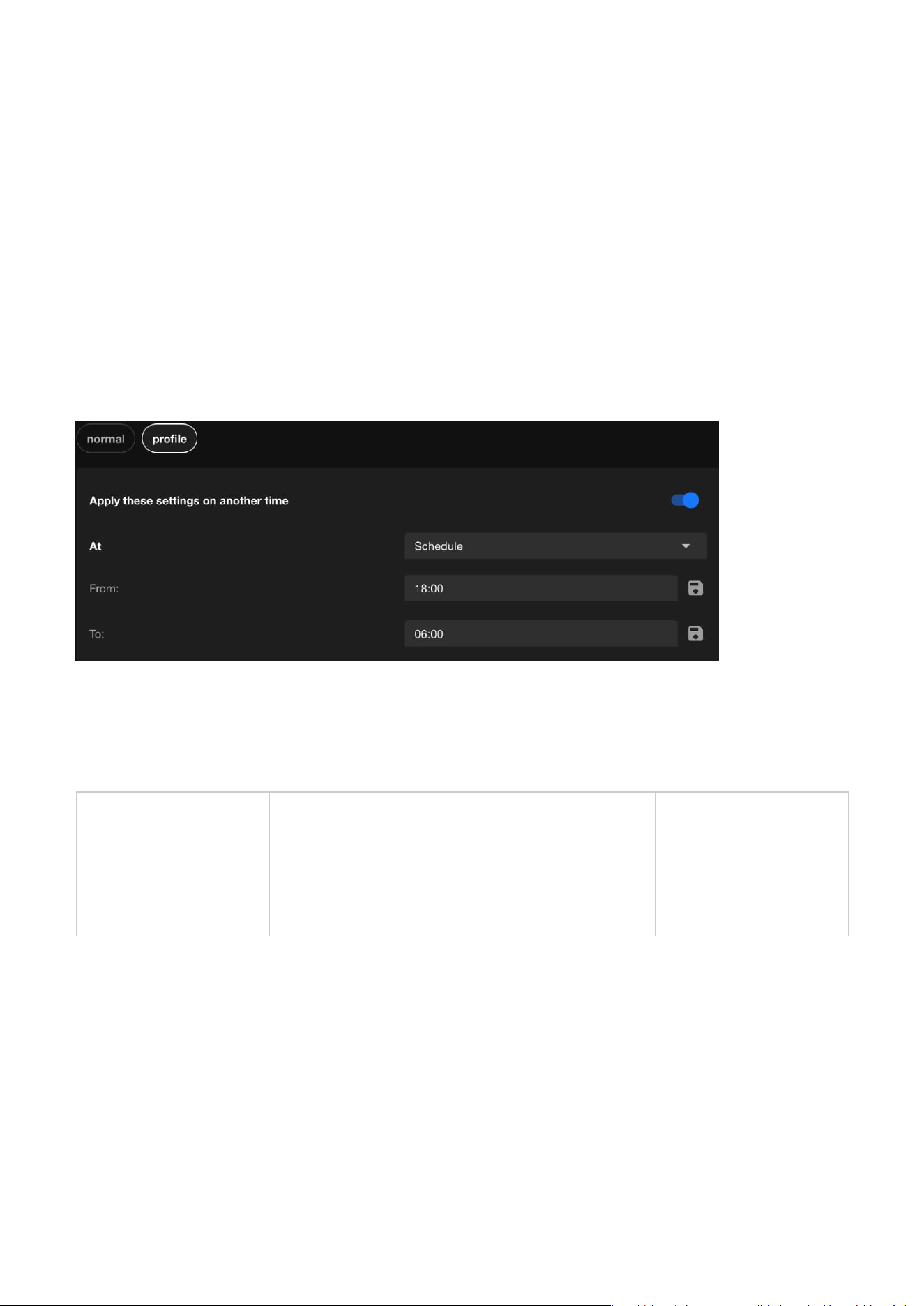
The normal mode in VIVOTEK cameras provides a baseline image configuration ideal for standard
monitoring. Through profile mode, specifically Night and Schedule, users can customize and automate
image settings based on specific requirements and time periods. This is not limited to day-night
transitions, offering greater flexibility and control.
This design delivers:
• Flexible and automated switching of image profiles.
• Optimized image quality for diverse scenarios.
33
3 Image
Full view
This option calculates the exposure based on the entire field of view, ensuring that the camera
considers all areas within the frame for exposure adjustments.
Center
When selected, the camera focuses on the central portion of the image to determine exposure
settings. This is beneficial when the main subject is located in the center of the frame, allowing for
optimal exposure in that area.
Normal
Provides standard image settings for general
use
Suitable for daytime or consistent lighting
environments
Night (Profile)
Optimizes image settings for low-light or
nighttime conditions
Enhances clarity and detail, ideal for night
surveillance
Schedule (Profile)
Automatically switches image settings based
on custom-defined time
Applies specific settings during designated
periods; not limited to day/night transitions
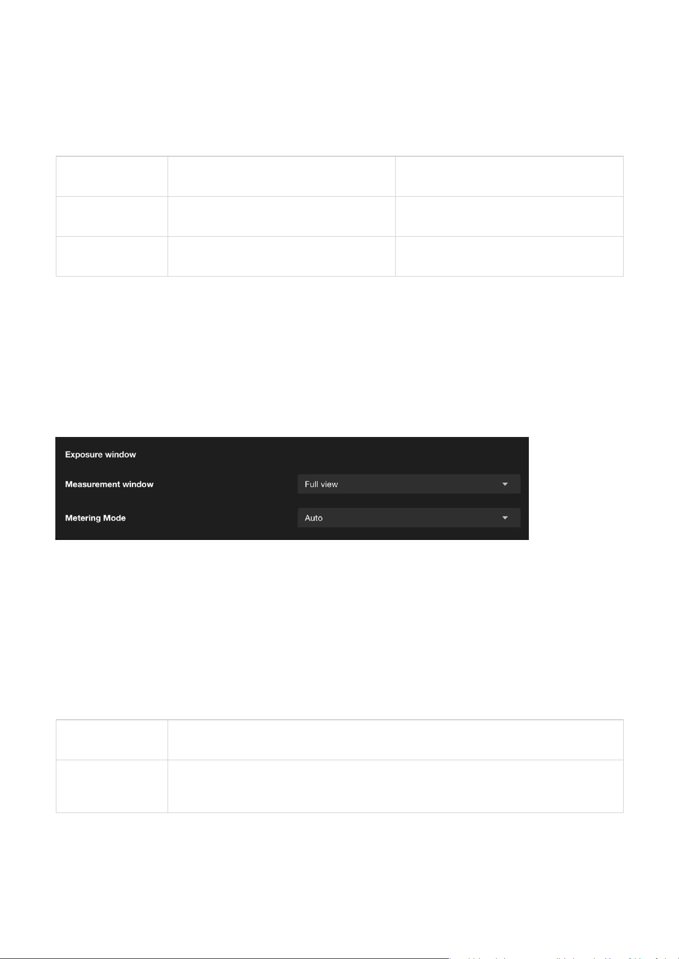
Exposure
Exposure window
Exposure Window is a feature that allows users to define a specific area within the camera's field of view
to optimize exposure settings. By focusing on this designated area, the camera can adjust its exposure
parameters to ensure that the area is properly illuminated, even in challenging lighting conditions. This
feature is particularly useful in scenarios where different areas of the scene have uneven light levels,
enabling the camera to prioritize exposure for critical regions and enhance overall image quality.
Measurement window
This function allows users to set measurement window(s) for low-light compensation. For example, when
low-light objects are positioned against an extremely bright background, user may want to exclude the
bright sunlight shining through a building's corridor. The types of measurement windows are as follows:
The Image page in the Camera web UI controls how much light the camera's sensor receives to create a
well-balanced image. Proper exposure ensures that the image is neither too bright (overexposed) nor too
dark (underexposed), allowing for clear visibility of objects in various lighting conditions.
•
Improved operational efficiency and resource management.
VIVOTEK cameras ensure consistent performance and high-quality surveillance tailored to various
conditions, enhancing both usability and monitoring effectiveness.
The purpose and applications:
34
3 Image
Auto
General purpose,
when the scene
lighting is balanced.
The camera automatically evaluates the entire scene to balance the
exposure.
It ensures that the overall brightness is optimized for typical scenarios.
Suitable for environments with relatively uniform lighting where no
extreme light sources dominate.
BLC
(Back Light
Compensation)
When the subject is
in front of a bright
light source.
Adjusts the exposure to address situations where the background is
much brighter than the subject (e.g., a person standing in front of a
bright window).
Ensures that the main subject is clearly visible and not underexposed,
even if the background becomes overexposed.
Ideal for scenes with strong backlighting.
HLC
(High Light
Compensation)
To manage
overexposed bright
spots and ensure
other areas are
visible.
Focuses on reducing the impact of overly bright light sources in the
scene, such as headlights, streetlights, or other intense light sources.
Darkens overexposed areas (like light spots) to enhance overall image
quality while preserving detail in darker regions.
Commonly used in nighttime or high-contrast environments where
bright highlights can obscure important details.
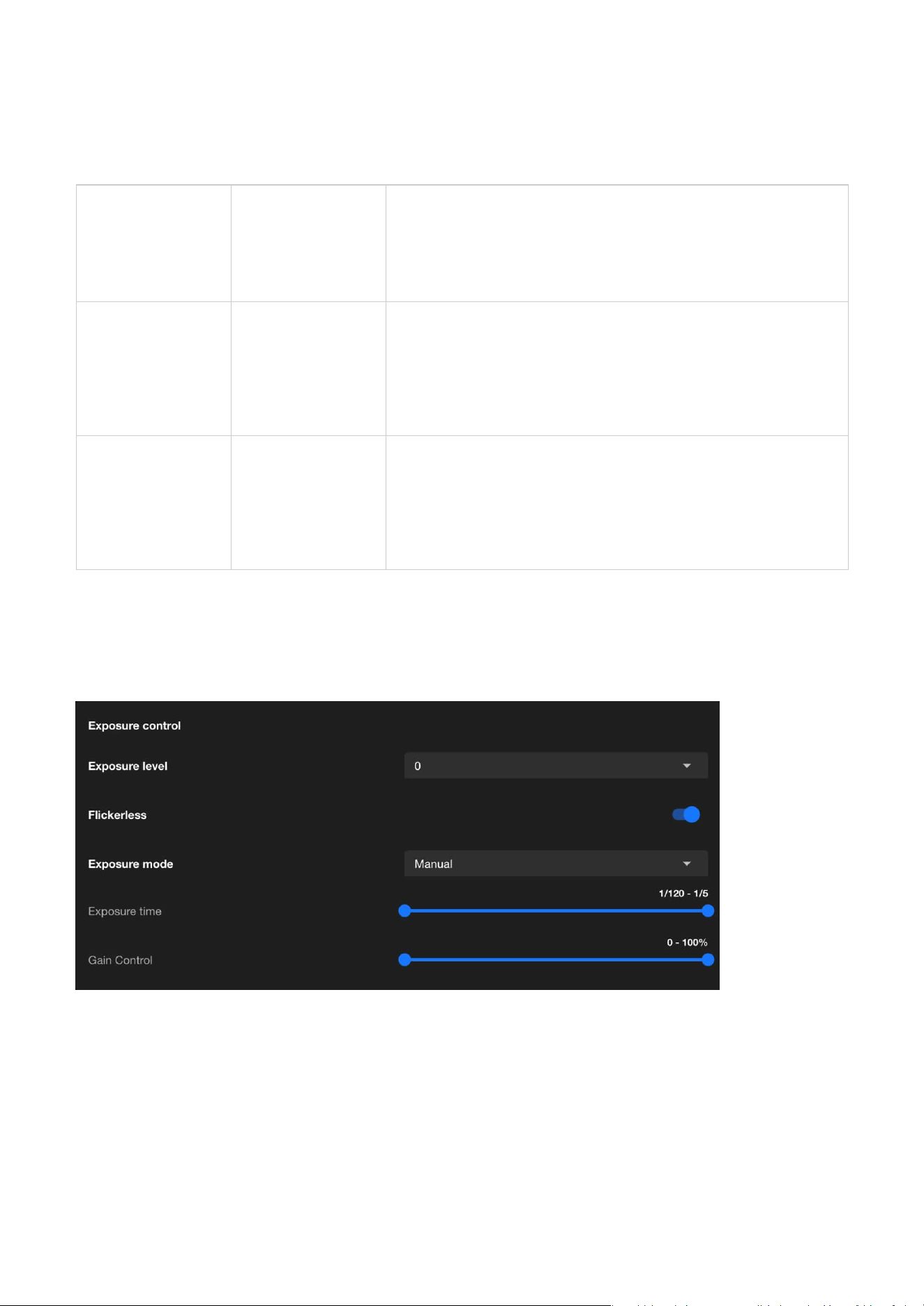
Exposure control
These settings help optimize the camera's performance for various lighting conditions, ensuring that
critical details are captured effectively.
Metering Mode
Metering Mode determine how the camera adjusts its exposure settings in response to different lighting
conditions:
Exposure Control is designed to manage how light interacts with the camera sensor to produce clear,
well-balanced images under varying lighting conditions. The primary purpose of exposure control is to
adjust the camera's settings to ensure optimal image brightness, clarity, and detail, regardless of the
environment.
Exposure level
The adjustment range of the Exposure Level is used to fine-tune the brightness of an image. This setting is
designed to enhance or reduce the exposure of the image based on ambient lighting conditions, ensuring
the image remains clear and retains complete details.

35
3 Image
Default
Provides automatic adjustment of exposure settings according to ambient lighting conditions.
Suitable for general environments where balanced image brightness is required without manual
configuration.
Shutter Priority
Maintains a fixed exposure time set by the user, while the system automatically adjusts gain to
ensure proper exposure. This mode is ideal for capturing fast-moving objects or scenes where
motion clarity is critical.
Iris Priority
Maintains a fixed iris (aperture) level set by the user, while the system automatically adjusts gain
to control brightness. Suitable for outdoor or variable-light environments where depth of field
control is important.
Manual
Provides full user control over exposure settings, including parameters like shutter speed and
gain.
Allows precise adjustments for environments with stable lighting or specialized applications where
exact configurations are required.
Suitable for controlled environments like offices, warehouses, or other spaces with fixed artificial
lighting.
Quality Priority
Optimizes exposure settings to prioritize image quality, automatically balancing iris and gain
adjustments. Recommended for scenarios where maintaining detail and clarity is more critical
than minimizing motion blur or noise.
Image unblur
Exposure time
Exposure Time refers to the duration for which the camera's sensor is exposed to light, typically
expressed in seconds or fractions of a second (e.g., 1/120 second to 1/5 second). The primary purpose
of this feature is to control the brightness and clarity of the image, especially under varying lighting
conditions.
Gain control
Gain Control is used to adjust the sensitivity of the camera's sensor to light. Gain settings are primarily
used to enhance image brightness in low-light environments, though they may increase image noise. This
feature helps the camera produce clear and visible images in low-light or high-contrast scenes.
Exposure mode
Exposure mode is used to control how the camera adjusts image exposure parameters (such as Exposure
time and Gain Control) to adapt to different ambient lighting conditions. Once the Exposure mode is
enabled and configured, it helps the camera automatically or manually adjust the exposure according to
scene requirements, ensuring that the image brightness and details meet the desired standards.
Image Unblur is a feature designed specifically for dynamic scenes, effectively reducing motion-induced
image blur to ensure clear images of fast-moving objects. By adjusting shutter speed and other exposure
parameters, this feature is ideal for scenarios requiring high-resolution dynamic recording, such as traffic
monitoring or crowd surveillance. However, reasonable adjustments between brightness and image
quality are necessary to achieve optimal results.
36
3 Image
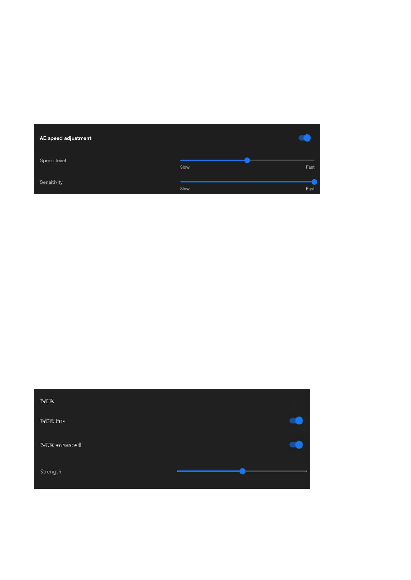
AE speed adjustment
WDR
AE Speed Adjustment controls the response speed of auto exposure to changes in lighting, balancing
the immediacy and stability of the image. Its purpose is to provide optimal image quality in different
scenarios, avoiding exposure instability or image flickering caused by lighting variations. By flexibly
adjusting the AE Speed, diverse surveillance needs can be met, ensuring clear and stable images.
Speed level
The speed level of AE Speed Adjustment should be configured based on the frequency of lighting changes
in the surveillance scene. A slower speed is recommended for stable scenes, while a faster speed is
suitable for dynamic scenes, ensuring that brightness adjustments are both smooth and responsive.
Through testing and fine-tuning, an optimal balance between image stability and clarity can be achieved.
Sensitivity
Adjusting the sensitivity in AE Speed Adjustment controls the camera's ability to perceive changes in
lighting. Low sensitivity is suitable for stable scenes, ensuring a steady image, while high sensitivity is
ideal for rapidly changing scenes, providing real-time response. By testing and tailoring the sensitivity to
the specific scene requirements, the optimal balance between light adaptability and image stability can
be achieved.
Image sharpener with auto shutter speed control
Combining Image sharpener with auto shutter speed control can effectively achieve image unblur. By
shortening the shutter speed to reduce blur and applying image sharpening techniques to enhance
details, the camera can deliver clear images in dynamic scenes while automatically adjusting other
parameters to balance brightness, meeting diverse surveillance needs.
The WDR (Wide Dynamic Range) feature is primarily used to enhance image quality in high-contrast
lighting scenarios, balancing the brightness of light and dark areas, preserving details, and ensuring
clear visibility. This feature is crucial for scenarios requiring precise monitoring under diverse lighting
conditions, such as entrances, tunnels, banks, or nighttime surveillance.
37
3 Image
Night (Profile)
Optimizes exposure for
low-light conditions
Lower shutter speed,
increased gain, balanced
exposure
Enhances visibility
in nighttime or dark
environments
Schedule (Profile)
Time-based switching of
exposure profiles
User-defined exposure
settings for specific time
periods
Adapts to custom
needs beyond day/night
transitions
Optimizing Image Clarity with Flexible Focus Controls
Focus settings
Integrate exposure-related settings into a profile
The Exposure settings in VIVOTEK cameras can be finely tuned using the Profile function, allowing
automated adjustments based on time (Schedule) or lighting conditions (Night/Normal). This ensures the
camera consistently delivers optimal image quality across varying lighting environments.
The purpose and applications:
WDR Pro
WDR Pro is an advanced wide dynamic range feature provided by VIVOTEK cameras, offering exceptional
image processing capabilities for high-contrast lighting scenarios. It effectively balances details and colors
in both bright and dark areas, ensuring overall image quality, making it an ideal choice for scenarios
demanding high standards in image detail and lighting management.
WDR enhanced
WDR enhanced is VIVOTEK's most advanced dynamic range technology for high-contrast scenes, offering
superior detail restoration in bright and dark areas compared to standard WDR and WDR Pro. It is suitable
for scenarios with extreme light contrasts and rapid changes, significantly enhancing image clarity and
stability, making it particularly ideal for surveillance applications requiring high detail fidelity. Strength
can be adjusted to increase or decrease the WDR effect depending on scene requirements.
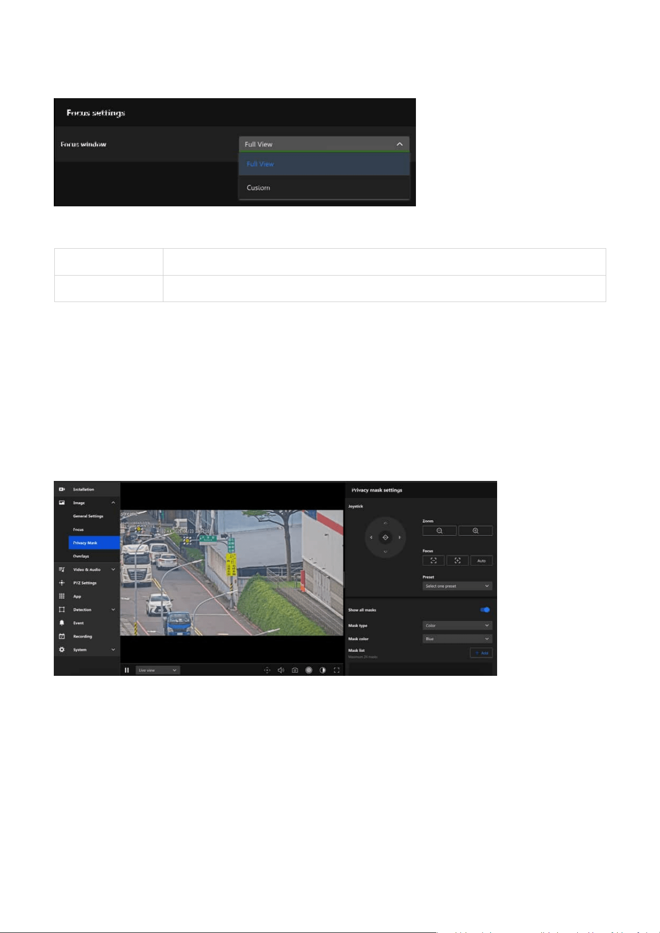
The Focus settings in the Image configuration is designed to ensure optimal image clarity and precision
for surveillance. It allows users to adjust the focus to achieve the best results for their specific monitoring
scenario. This section provides tools for both automatic and manual adjustments, catering to dynamic or
static scenes, various distances, and lighting conditions.
38
3 Image
Full View The entire field of view is considered for focus.
Custom Users can select a specific area for focus optimization
Using Privacy Masking to Safeguard Confidential
Information in Images
Focus window
The primary purpose of setting up a Privacy Mask is to protect privacy, comply with regulatory
requirements, and enhance surveillance efficiency. By flexibly applying the privacy masking feature in
various scenarios, it not only prevents unnecessary privacy violations but also allows a focus on key
surveillance areas, improving overall monitoring effectiveness and compliance.
The main benefits of setting up a Privacy Mask are as follows:
• Complies with privacy regulations, reducing legal risks.
• Avoids capturing footage unrelated to surveillance purposes, improving data processing efficiency.
• Reduces privacy intrusion on monitored subjects, enhancing trust and acceptance.
• Keeps the focus on target areas, minimizing distractions and improving surveillance effectiveness.
Allows the user to define the area within the camera’s view where the focus should be optimized.
39
3 Image
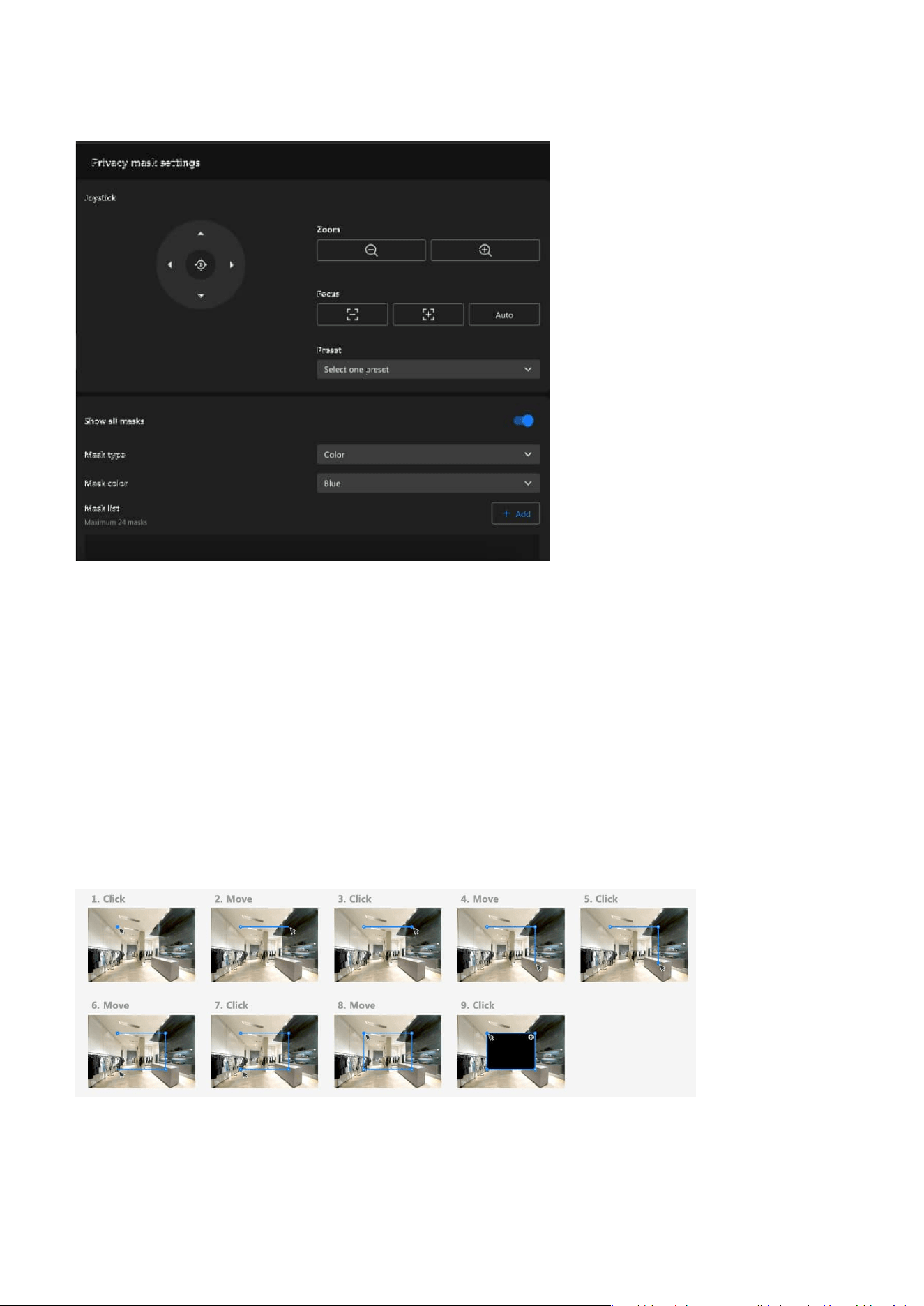
Privacy mask settings
Step 3. Step 3. Enter the privacy mask name.
Step 4. Step 4. Click Save button.
Joystick
Users can move the view using the joystick to position the image over the area where a privacy mask is
to be set. Additionally, pressing the Home button will restore the view to the preset Home position. The
Home position can be configured in PTZ Settings > Home & Preset.
Steps to add a privacy mask:
Step 1. Click +Add button in the Mask list.
Step 2. Draw a closed shape to cover the region you want to hide for privacy concerns on the preview
screen.
TIP
When drawing the mask, note that during PTZ movement, coordinate and zoom adjustments may cause
the masked object to become partially exposed. To prevent this, draw the mask slightly larger and test to
confirm sufficient coverage.
40
3 Image
Customizing Image Overlays to Add Additional
Information
The Overlays feature is a powerful tool that enhances the usability and clarity of video streams or
recordings by allowing key information to be superimposed on the video feed.
Steps to edit the privacy mask:
Step 1. Click edit icon on the mask item.
Step 2. Drag the mask to the desired Area.
Step 3. Click and drag the corners to adjust the shape (rectangular, trapezoidal, etc.) and size to precisely
cover the target area
Step 4. Click Save button.
Show all masks
After the user configures the privacy masks, the "Show all masks" must be enabled to apply the
configured masks to the image.
Mask type
The privacy mask feature provides Color masking to meet privacy protection needs in various scenarios.
Color masking is suitable for situations requiring a high level of privacy and complete concealment of
sensitive areas. Applying the appropriate mask ensures effective and reliable privacy protection.
Mask color
Users can select a mask color from a predefined palette using the Mask Color dropdown menu when
creating a new privacy mask. Available colors include black, multiple shades of gray, white, red, green,
blue, cyan, yellow, and magenta. This allows users to match the mask appearance to different application
needs or visual preferences.
Steps to delete the privacy mask:
Step 1. lick delete icon on the mask item.
Step 2. The Mask item will be deleted directly.
Below is an explanation of its main purposes and functionalities:
• Displaying Key Information:
Adds essential details such as the camera name, date and time, location, or custom text to the video,
41
3 Image
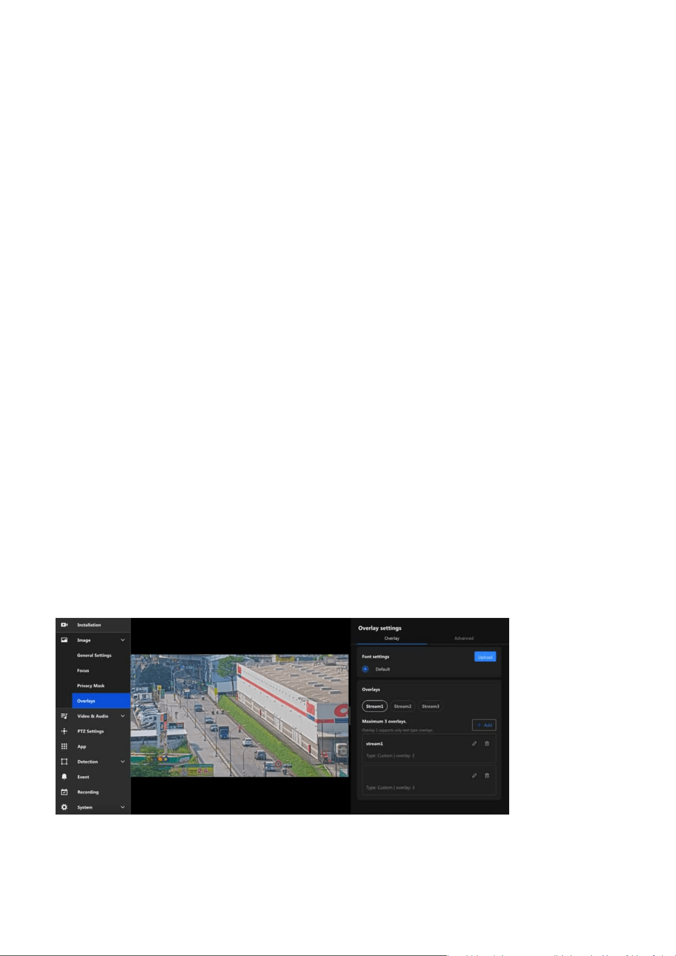
Overlay
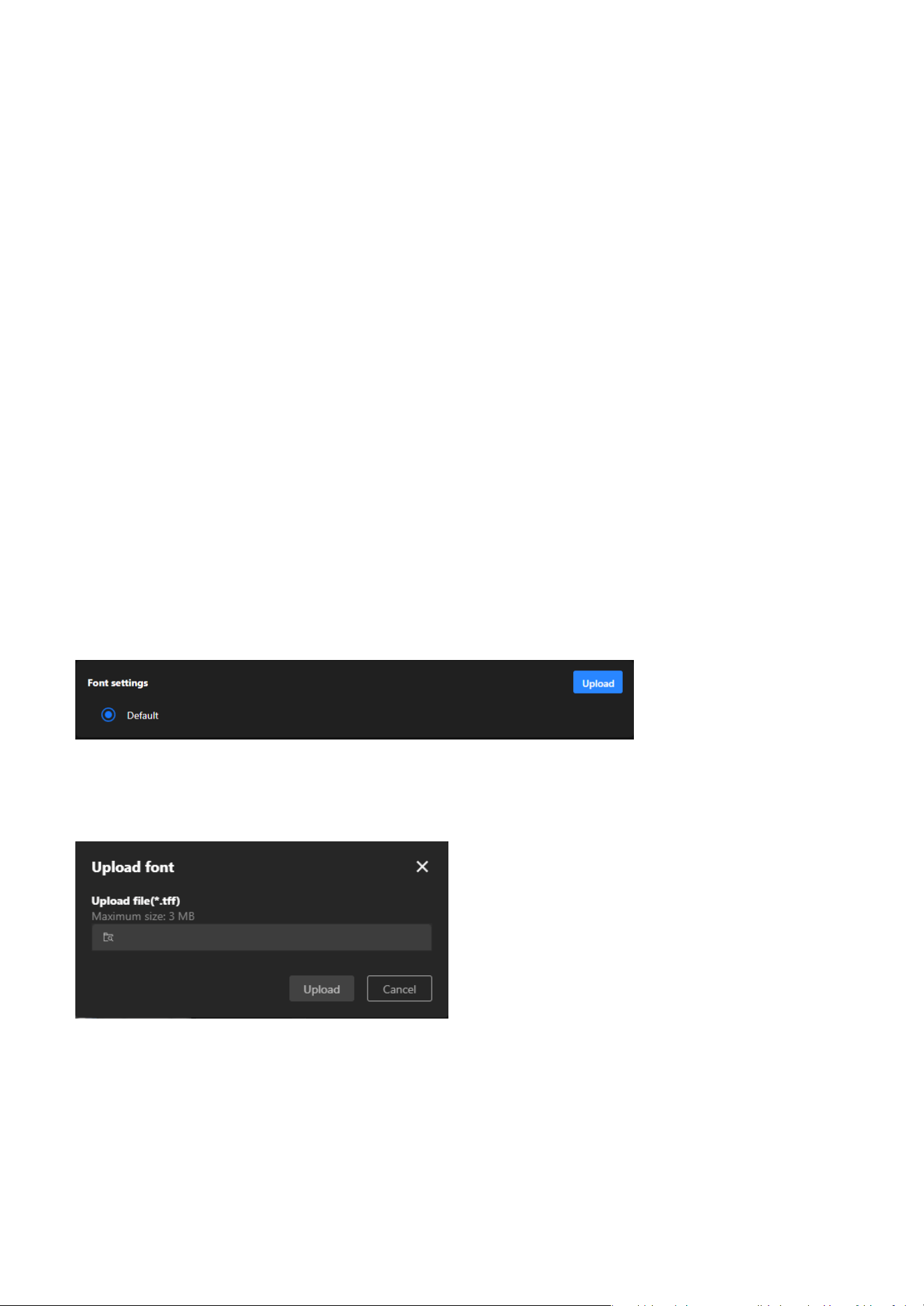
Font settings
The Overlay allows users to add information to images, such as camera names and timestamps. This
information is directly displayed on recorded or live-streamed footage, facilitating future review and
management. For instance, by enabling the overlay function, you can display the camera's name and the
recording time on the footage, which is highly beneficial for surveillance system management and event
tracing.
The Font Settings in the Overlay settings allow users to customize the appearance of text overlays on
video feeds. This feature ensures that the displayed information is clear, visible, and matches the specific
requirements of different monitoring environments.
making it easier to identify the source and context of the footage.
• Enhancing Evidence Validity:
Timestamp overlays ensure that video recordings can serve as valid evidence for legal or investigative
purposes.
• Branding and Identification:
Displays logos or other identifiers to reinforce brand recognition, especially useful in commercial or
public applications.
• Real-time Data Monitoring:
With dynamic text overlay, real-time updates (e.g., sensor data, alarms) can be shown directly on the
video feed, making it valuable for environment monitoring or situational awareness.
• Regulatory Compliance and Alerts:
Ensures adherence to specific industry or regional regulations by displaying required notifications or
warning messages on the video feed.
42
3 Image
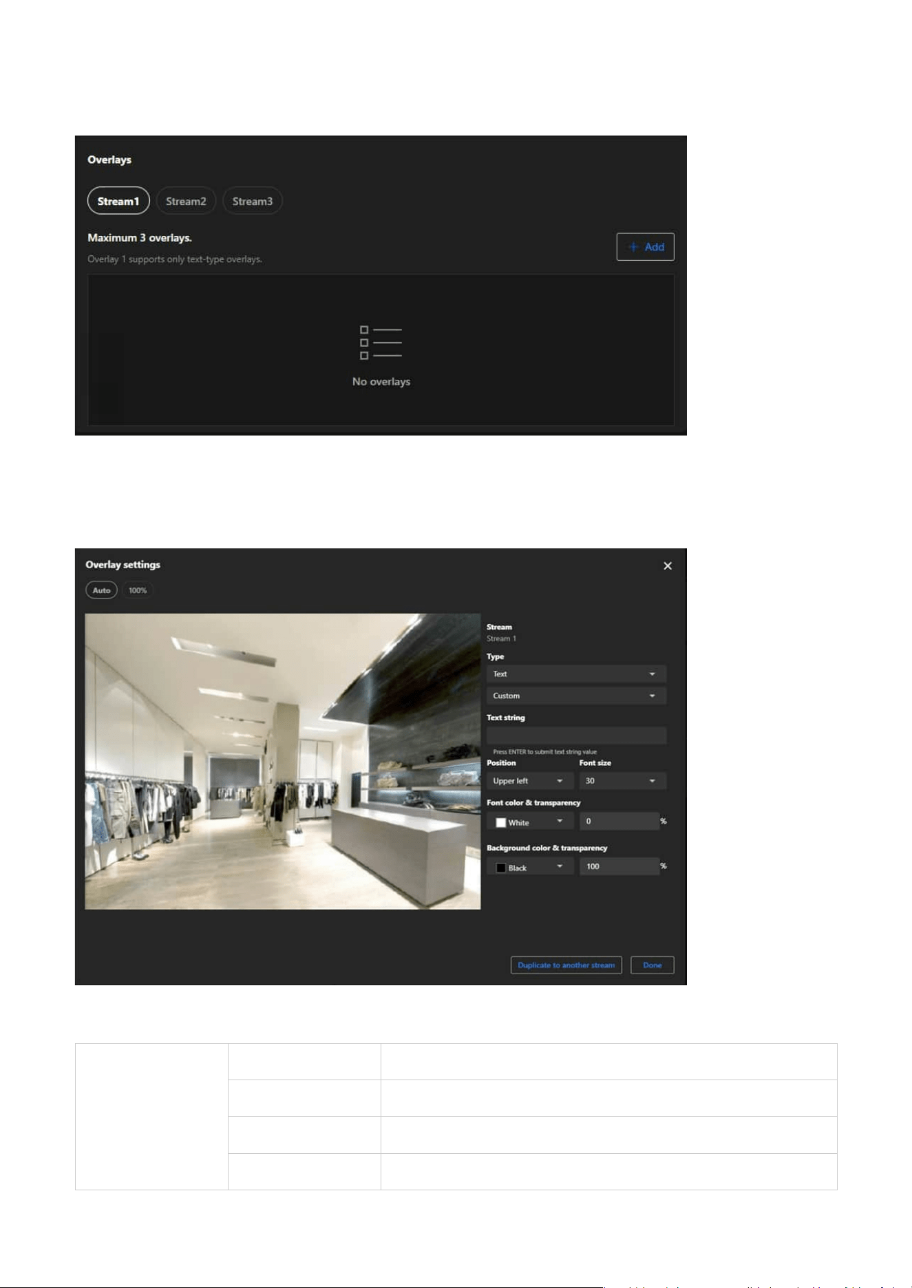
Step 3. Choose the type of overlay:
Step to set an overlay:
Step 1. Select the stream (e.g., Stream 1, Stream 2, or Stream 3) you wish to configure for overlay.
Step 2. Click the Add button to create a new overlay.
Overlays
Text
Date and Time The display can show the user-defined date and time format.
Date The display can show the user-defined date format.
Time The display can show the user-defined time format.
Custom The display can show user-defined text content.
43
3 Image
Image The display can show 256-color BMP images uploaded by the user.
Live streaming
indicator
The Live streaming indicator is a feature within the Overlay settings
that visually indicates when the camera is actively streaming live video.
Advanced
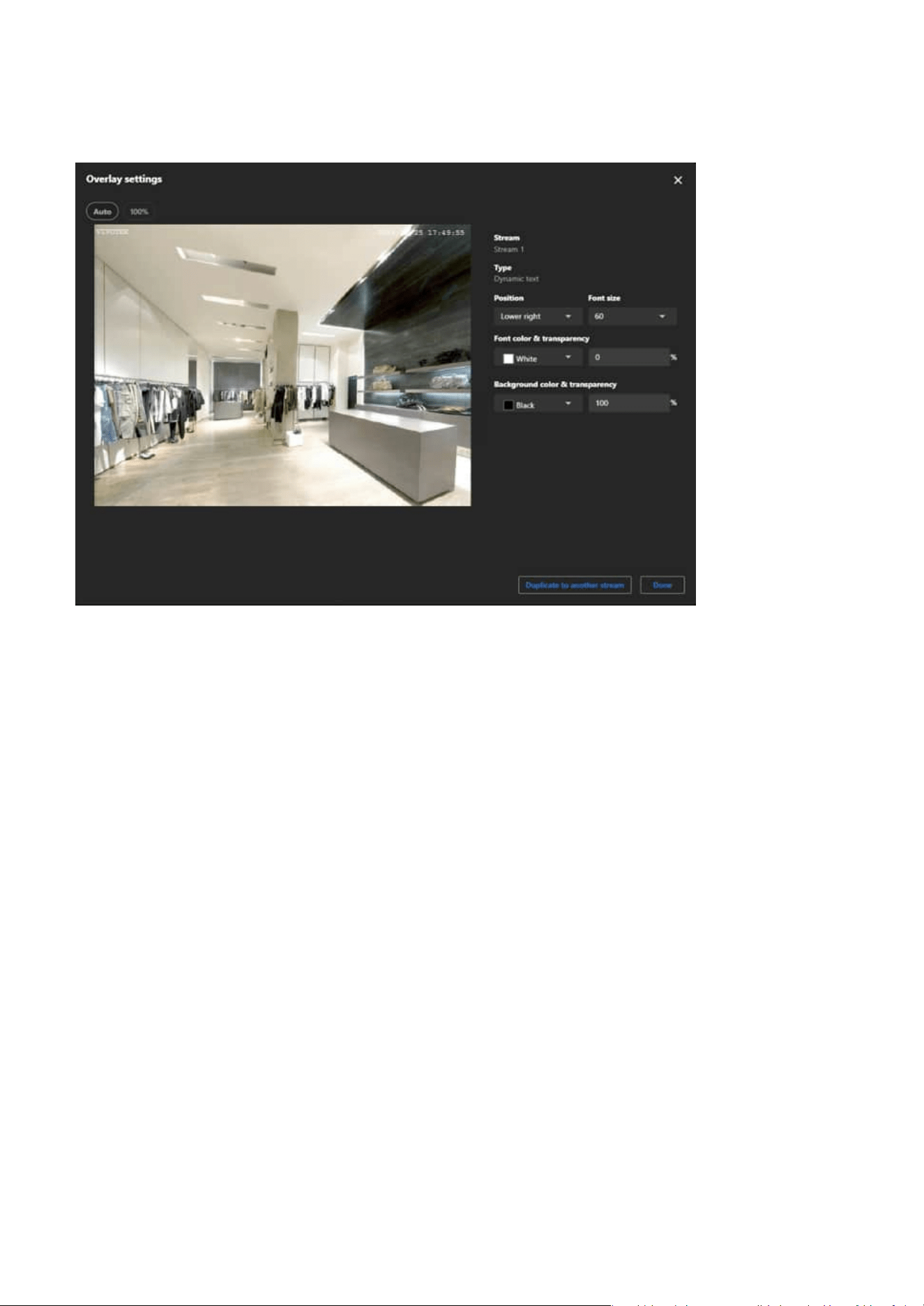
Dynamic Text Overlay
Dynamic Text Overlay is an advanced feature of VIVOTEK cameras that allows users to display real-time
dynamic information from external data sources on surveillance footage. This feature enhances the
practicality and informational value of the footage, making it suitable for various surveillance scenarios.
The Advanced page in the Overlay settings primarily offers advanced features, enabling users to
customize overlay content on surveillance footage according to specific requirements. Particularly
useful for displaying real-time dynamic data or in professional scenarios, this settings page provides the
necessary flexibility and functional support.
Step 4. Click the Position dropdown menu to place the overlay (e.g., Upper Left, Bottom Right). Adjust
positioning manually if advanced controls are available.
Step 5. If you select Text, Click the Font size dropdown menu to adjust the text size.
Step 6. If you select Text, please click and configure the Font and Background dropdown menus to choose
the appropriate color and transparency.
Step 7. If you select Image, please click and configure the Image transparency dropdown menus to
choose the appropriate transparency.
Note
For image overlays, ensure the size and resolution fit the video stream properly.
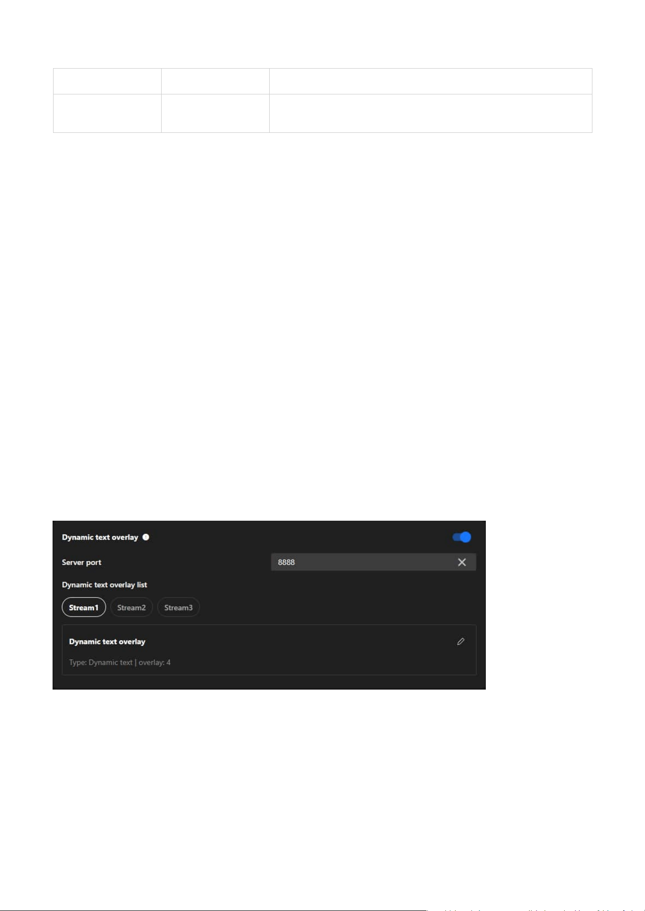
Steps to set the dynamic text overlay:
Step 1. Enable Dynamic text overlay
Step 2. Ensure the Server Port is set to an available port (default: 8888) or specify another unused port if
necessary.
Step 3. Ensure your external data source is configured to send data to the camera’s IP address and the
specified server port (e.g., 8888).
Step 4. Ensure the data format is compatible with the camera's requirements.
44
3 Image
Step 5. Select the stream you want to add the dynamic text overlay to.
Step 6. In the "Dynamic Text Overlay List," click the Edit (pencil icon) to configure overlay details.
45
Video & Audio
3
Optimizing Surveillance Efficiency with Flexible Video
Settings
Video mode
The main purpose of Video & Audio settings is to ensure high-quality video and audio by adjusting
resolution, frame rate, and compression formats, while optimizing bandwidth and storage usage with
multi-stream options. These settings enhance monitoring capabilities with high resolution, smooth frame
rates, and two-way audio, and provide adaptability for various scenarios such as night mode or outdoor
environments. Additionally, they improve system flexibility and compatibility by supporting multiple
media formats and protocols for seamless integration across devices.
The Video settings are divided into the Mode page and the Stream page, both primarily used for
configuring the camera's video output, offering users flexible control over video quality and resource
management.
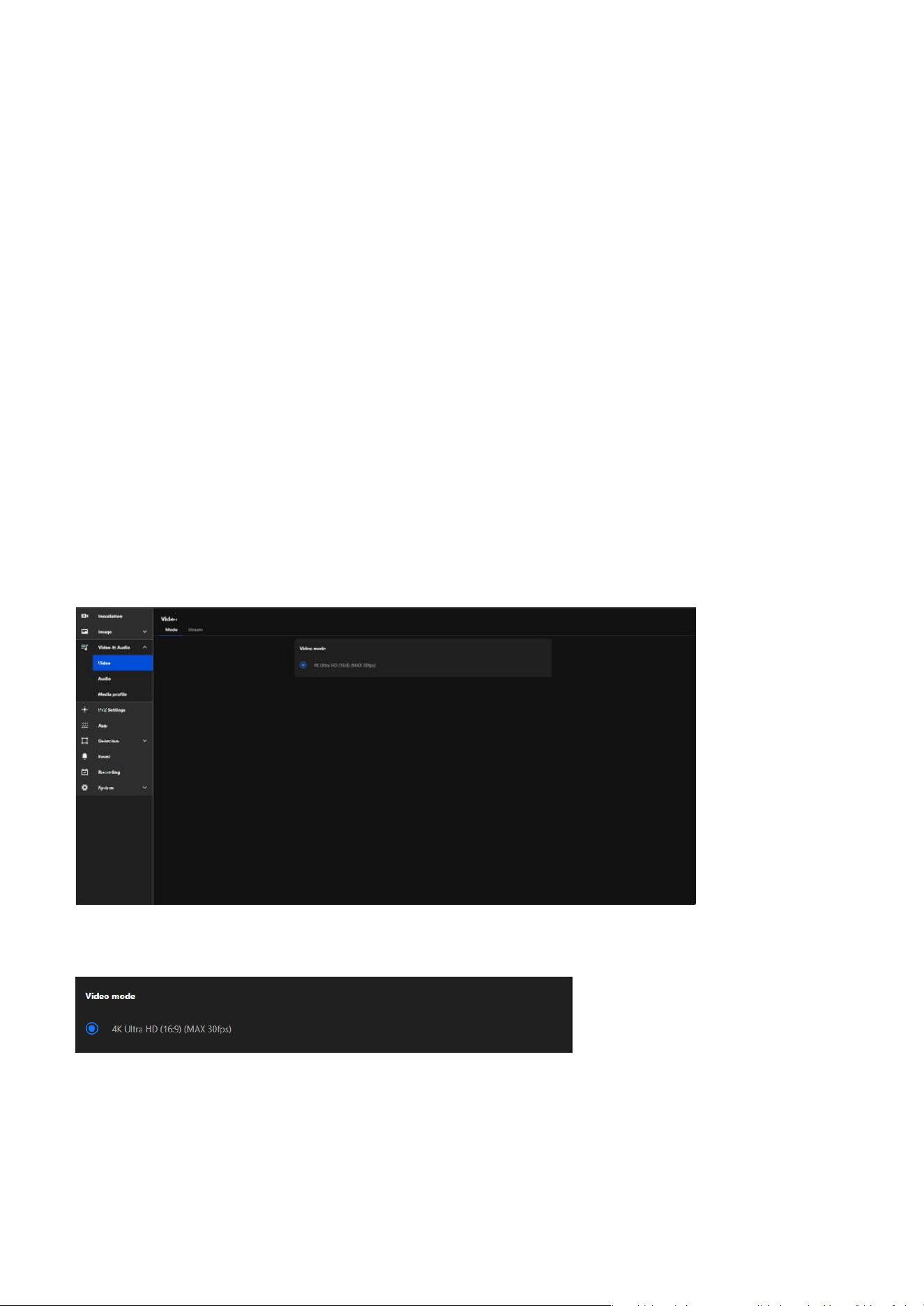
Video mode allows users to customize the camera's video performance to meet specific monitoring needs
while achieving a balance between high-quality video output and resource efficiency. The main features
are as follows:
• Defines Video Resolution
The Video Mode determines the maximum resolution the camera can output, such as 4K Ultra HD, Full
HD, or other resolutions, ensuring high-quality video feeds.
46
3 Video & Audio
Codec Compression Description
MJPEG Low (large file size)
Highest image quality, but requires large
bandwidth and storage.
H.264 Medium
Balanced quality and compression; widely
supported.
H.265 High (half of H.264)
Same quality at half the bitrate; ideal for high-
resolution video.
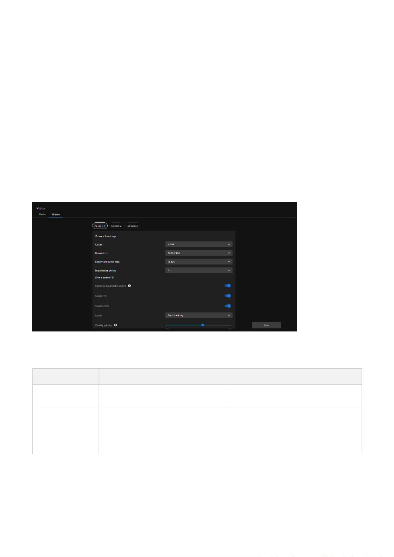
Video stream
Video Stream is designed to offer flexible video output options to meet diverse surveillance needs while
optimizing bandwidth and storage resource usage. Through multi-stream configuration, intelligent
compression technology, and regional optimization, Video Stream serves as a key tool for enhancing
surveillance efficiency and adaptability across various applications.
Codec
Defines the video compression format.
• Sets Aspect Ratio
Configures the aspect ratio of the video (e.g., 16:9), optimizing the field of view for modern widescreen
displays.
• Controls Frame Rate
Specifies the maximum frames per second (fps), such as 30fps, for smooth motion capture in dynamic
environments.
• Establishes Video Parameters
Sets the overall video performance limits, including resolution and frame rate, which affect the clarity,
smoothness, and resource usage of the video stream.
Resolution
Resolution is a key parameter of image quality, directly affecting the clarity of surveillance footage,
storage requirements, and bandwidth usage. Choosing the appropriate resolution requires considering
the monitoring purpose, scenario needs, and resource constraints.

47
3 Video & Audio
High-Speed Motion (e.g., Traffic, Sports) 30fps or higher
Smoothly captures fast-moving scenes,
suitable for scenarios requiring clear
observation of moving objects.
General Surveillance (e.g., Stores, Offices) 15fps
Balances video smoothness and bandwidth
usage, ideal for most everyday monitoring
needs.
Static Scenarios (e.g., Warehouses, Parking
Lots)
10fps or lower
Saves resources, suitable for scenarios
emphasizing static environments.
Low-Bandwidth Environments or Remote
Monitoring
5fps
Reduces bandwidth usage, ideal for situations
with network constraints or basic monitoring
requirements.
High-Frequency Frame Updates
(e.g., AI-assisted detection, frame-level
analysis)
1/2 or 1/4 second
Increases I-Frame frequency for enhanced
temporal resolution, suitable for scenarios
requiring precise frame analysis or low-
latency processing.
High-Dynamic Scenarios (e.g., Traffic
Monitoring)
1 second
Quickly generates complete frames, suitable
for capturing fast-moving targets.
General Surveillance (e.g., Offices, Stores) 2 seconds
Balances video clarity, bandwidth, and
storage usage, ideal for most daily
surveillance scenarios.
Static Scenarios (e.g., Warehouses) 3 seconds or longer
Reduces the number of I-Frames to save
resources, suitable for low-variation scenes.
Remote or Low-Bandwidth Monitoring 1–2 seconds
Prevents image degradation and ensures
smoothness and quality in remote viewing.
Maximum frame rate
Maximum frame rate is a parameter that determines the number of video frames captured and
transmitted by a camera per second. Frame rate affects the smoothness of the video, detail capture,
bandwidth usage, and storage requirements. Choosing an appropriate frame rate requires considering
the monitoring scenario, purpose, and system resources. Recommended frame rate settings as:
Intra frame period
Intra Frame Period determine how often for firmware to plant an Intra frame (I-frame). The shorter the
duration, the more likely user will get better video quality, but at the cost of higher network bandwidth
consumption. Recommended settings based on use cases:
Smart stream III
Smart Stream III is an advanced video optimization technology in VIVOTEK cameras, focusing on
dynamically managing bandwidth and storage usage while maintaining critical details and image quality.
This technology effectively reduces bandwidth and storage requirements by intelligently adjusting frame
rates, compression ratios, and regional quality, making it particularly suitable for scenarios with limited
bandwidth or requiring long-term recording. The configuration items for Smart Stream III are as follows:
• Dynamic intra frame period
Automatically adjusts the I-frame frequency based on scene activity. Achieves better optimization by
balancing image clarity and resource usage.

48
3 Video & Audio
Auto Tracking
• High-dynamic scenarios (e.g., traffic, public spaces)
•
Automated processing, no manual configuration needed
•
Cannot focus on specific static areas
Quality priority
Quality Priority is a parameter used to define the priority of image quality, providing higher or lower
image quality for specific ROI areas to balance resource usage and image clarity.
Bit rate control
Bit rate control is used to adjust the transmission bit rate of video, achieving a balance between image
quality and bandwidth usage.
• Fixed Quality
When the surveillance scenario demands high image quality and network and storage resources are
relatively sufficient, it is recommended to use Fixed Quality to ensure that no image details are lost.
• Constrained Bit Rate
If the surveillance environment has limited bandwidth or storage resources, it is recommended to
choose Constrained Bit Rate to precisely control resource usage by limiting the bit rate.
Target quality
Target Quality sets the target quality level of the video, instructing the camera on how to compress the
video to achieve the desired clarity. The purpose and applications:
• Smart FPS
Dynamically adjusts the frame rate based on motion in the scene. High motion increases the frame rate
for smoothness, while low motion decreases it to save bandwidth.
• Smart codec
Utilizes advanced compression technology to maintain detail in high-motion areas while heavily
compressing static areas. Optimizes bandwidth and storage usage without losing critical information.
• Mode
Defines how the camera manages the ROI (Region of Interest) in the video and optimizes image quality
and resource allocation. Mode offers different operating options, allowing users to flexibly choose auto
tracking, manual, or hybrid ROI settings based on surveillance needs and scene characteristics.
Option Purpose Effect on Stream Application
Customized User-defined quality settings
Manual adjustment for precise
stream control
Scenarios requiring tailored
stream parameters
Medium
Lower requirements for target
quality
Lower quality, reduced bitrate
Low-priority streams or low-
bandwidth networks
Standard Balances quality and efficiency
Moderate quality with
controlled bitrate usage
General-purpose monitoring
Good Enhances stream clarity
Better detail while keeping
bitrate reasonable
Busy areas with moderate
detail requirements
Detailed
Provides high detail in the
video stream
Higher quality, sharper
images, increased bitrate
Surveillance requiring detailed
object clarity
Excellent Maximizes stream quality
Highest image clarity and
bitrate usage
High-security monitoring,
critical evidence recording
49
3 Video & Audio
Frame Rate
Priority
Suitable for dynamic monitoring scenarios, ensuring smooth video playback to facilitate real-time
monitoring and quick response.
Image Quality
Priority
Suitable for static or detail-demanding scenarios, providing higher image clarity to record critical
details effectively.
Configuring Audio Settings for Enhanced Input and
Output Performance
The overall functionality of this page is designed for comprehensive management of the camera's audio
features, covering everything from real-time audio input and output to managing audio clip playback.
Smart Q
Smart Q is an intelligent image management feature designed to dynamically balance image quality and
resource utilization efficiency. It not only enhances the effectiveness of surveillance footage but also
improves the utilization of bandwidth and storage resources. This is particularly suitable for scenarios
requiring long-term recording, attention to detail, or resource-constrained monitoring systems.
Maximum bit rate
Maximum Bit Rate is a feature used to limit the bit rate of the camera's video stream, aiming to control
bandwidth and storage resource usage while maintaining video quality. Properly configuring the
Maximum Bit Rate not only ensures stable system operation but also effectively optimizes resource
allocation, making it an essential tool in multi-camera systems and low-bandwidth environments.
Policy
The function and purpose of the policy are to achieve flexibility and specificity in video transmission,
balancing frame rate and image quality according to scenario requirements, thereby enhancing the
effectiveness, stability, and resource utilization efficiency of the monitoring system.
Its purposes include:
• Enhancing overall surveillance effectiveness by leveraging audio to support video for more efficient
security monitoring.
50
3 Video & Audio
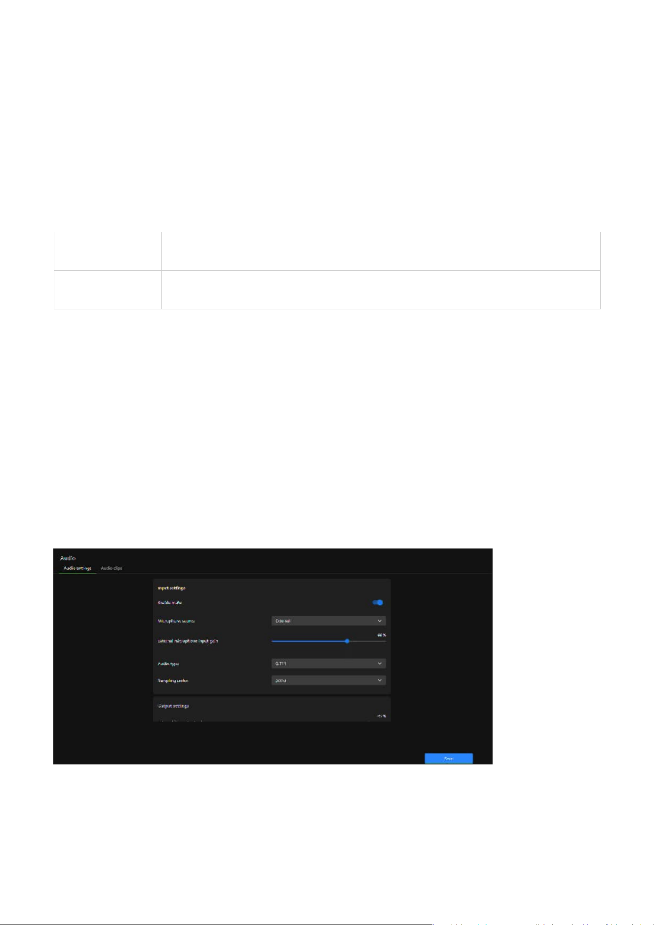
Audio settings
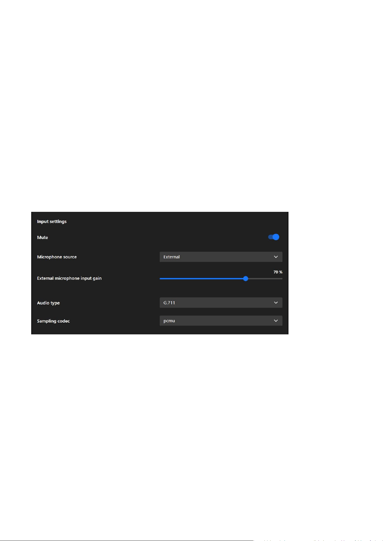
Input settings
The purpose of this setting is to provide detailed configurations for audio input and output, optimizing
the audio functionality of surveillance cameras and allowing users to adjust audio quality, volume, and
source based on their specific needs.
The purpose of this setting is to provide detailed configurations for audio input and output, optimizing
the audio functionality of surveillance cameras and allowing users to adjust audio quality, volume, and
source based on their specific needs.
• Improving communication and incident response capabilities by integrating two-way communication
and alarm features to meet diverse situational needs.
• Providing flexible control and management tools, enabling easy configuration for both real-time audio
processing and pre-recorded audio playback.
These features make the application of audio in surveillance environments more flexible and efficient.
Mute
Mute allows users to disable audio input, ensuring privacy or preventing unwanted sound recording.
Microphone source
Microphone source lets users select between Internal or External microphones to adapt to different audio
capture needs and hardware setups.
Internal/External microphone input gain
Internal/External microphone input gain allows users to adjust the microphone's sensitivity, enhancing
or reducing audio capture levels to suit varying environmental noise conditions and ensure clear sound
recording.
Note
The External microphone option is available only for models that support External Mic In or Line Out.
Audio type
The audio type setting determines the encoding format for audio, balancing quality, bandwidth usage,
and compatibility:
51
3 Video & Audio
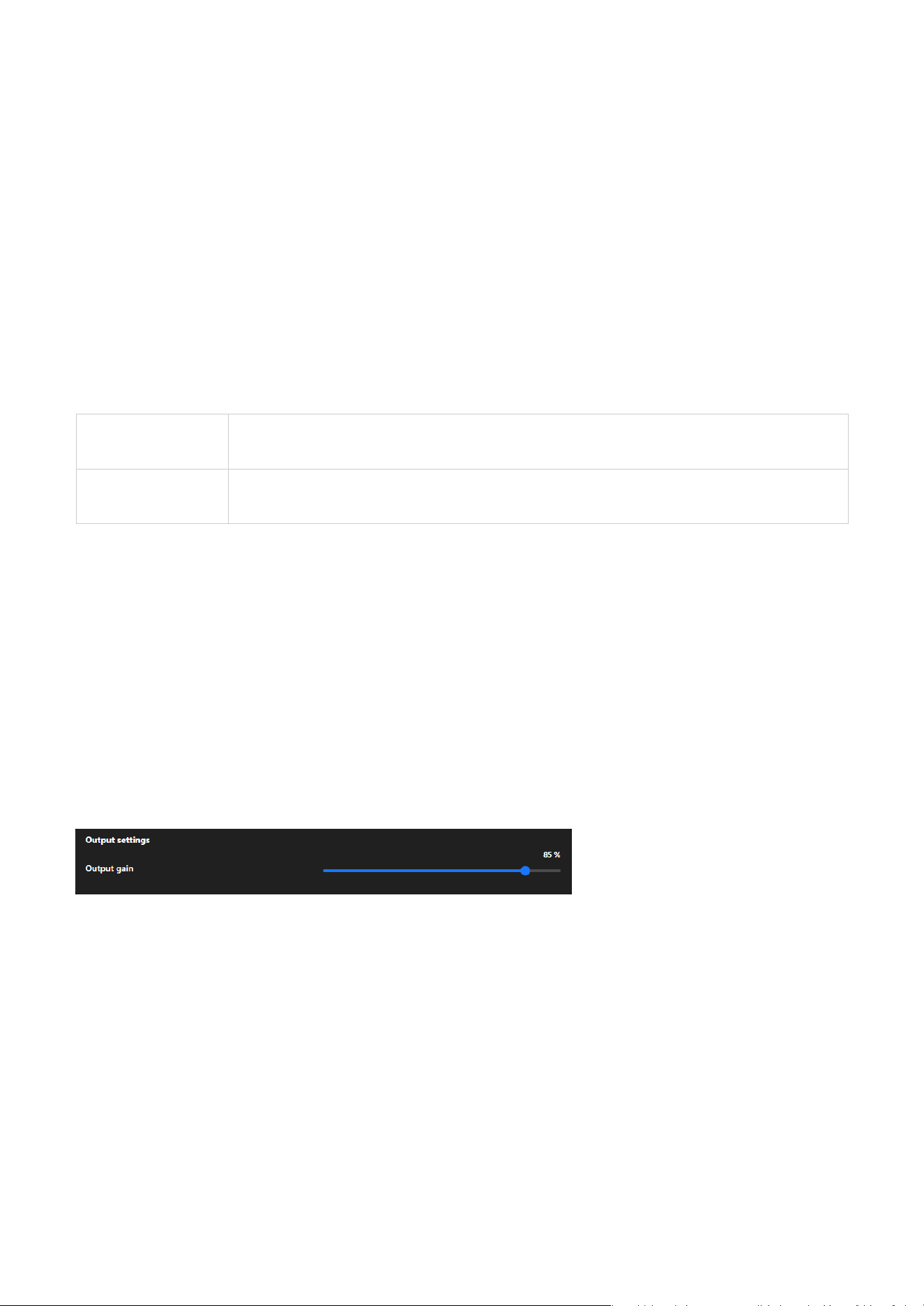
Output settings (The setting is displayed only for models that support DI/DO)
Output gain
Users can manually adjust the audio output volume to suit different application environments:
• In scenarios requiring high volume (such as alarms or wide-area broadcasts), gain can be increased to
enhance the volume.
• In scenarios requiring lower volume (such as privacy mode or silent operation), gain can be reduced to
minimize audio interference.
Users can manually adjust the audio output volume to suit different application environments.
• G.726
Provides moderate compression, balancing quality and bandwidth usage, suitable for environments
with bandwidth constraints.
• G.726 Bit Rate
G.726 Bit Rate is a specific configuration option that appears based on the selection of Audio Type
and is only active when G.726 is chosen. This option allows users to further adjust the encoding bit
rate to optimize settings according to practical needs, such as network bandwidth or storage space
limitations.
• AAC
Offers high-quality audio with efficient compression, ideal for environments requiring clear sound with
minimal distortion.
• AAC Bit Rate
AAC Bit Rate is a sub-setting under Audio Type, which only appears when AAC is selected. It is used
to fine-tune the quality and resource usage of AAC audio format, enabling users to optimize the
configuration based on practical scenarios, such as bandwidth or storage requirements.
• G.711
A widely used codec for real-time communication, providing good audio quality with low compression,
suitable for networks with sufficient bandwidth.
• Sampling codec
Defines the compression method for the selected audio type (typically G.711), affecting audio quality
and compatibility:
pcmu
Commonly used in North America and Japan, it provides slightly higher audio quality with a focus
on maximizing dynamic range for voice clarity.
pcma
Commonly used in Europe and other regions, it delivers comparable quality to pcmu but is
optimized for different telecommunication standards.
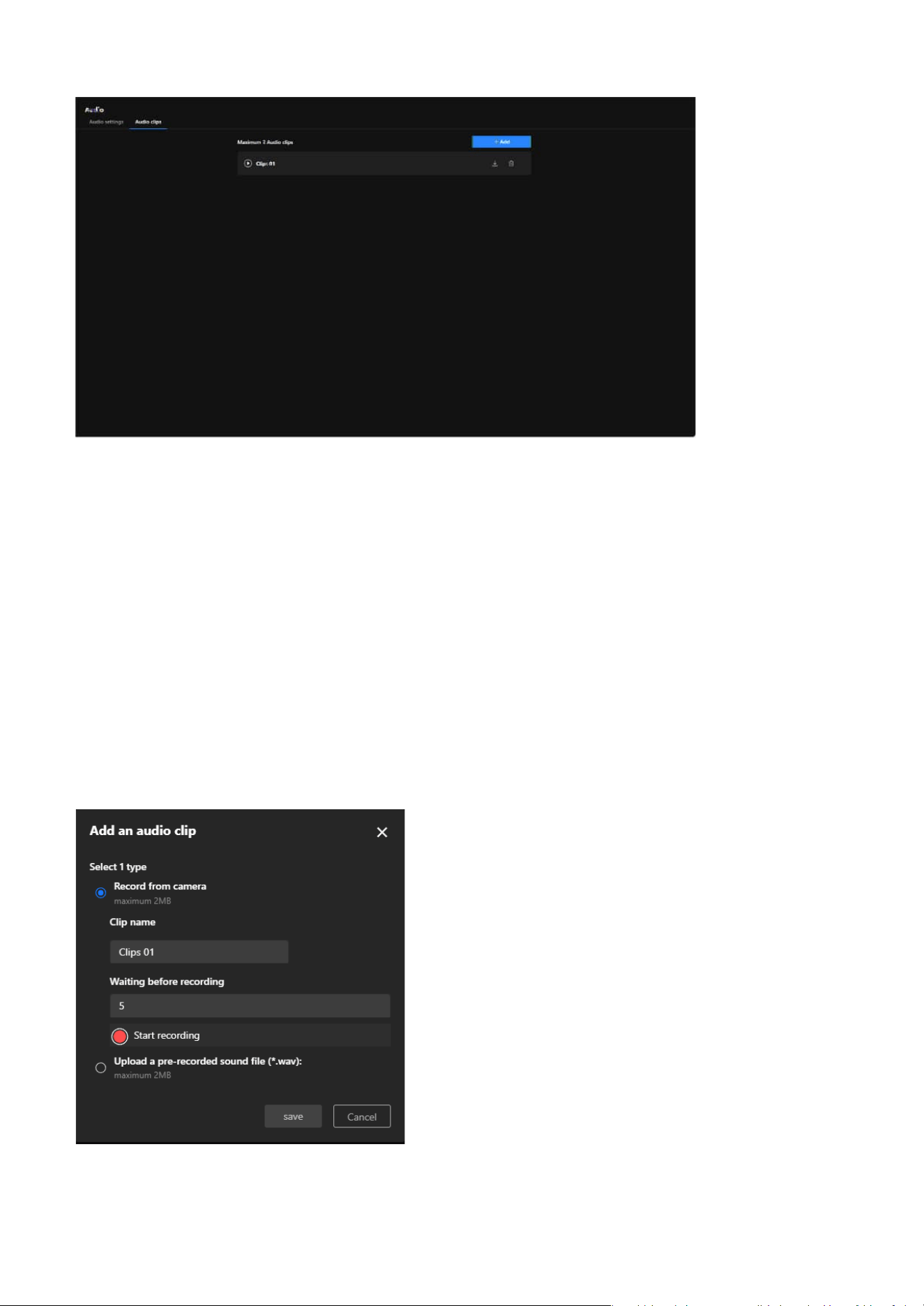
Audio clips (The setting is displayed only for models that support DI/DO)
The Audio Clips feature is designed to integrate audio with event triggers, enabling more efficient
notifications, alerts, and interactions, thereby enhancing the application value of cameras in surveillance
and security scenarios.
52
3 Video & Audio
The purpose of the functionality:
• Enhance Incident Response Capability
By playing audio alerts or notifications, it can promptly notify nearby personnel of anomalies or
potential threats.
• Strengthen Security Deterrence
Play pre-recorded warning messages or alarm sounds upon detecting intruders or suspicious activities,
effectively deterring potential threats.
• Increase Monitoring Flexibility
Support for customizable audio content to cater to various scenarios, such as playing welcome
messages in stores or broadcasting regulatory instructions in parking lots.
• Simplify Operational Processes
Automated audio playback reduces the need for manual operations, further improving surveillance
efficiency.
Steps to add an audio clip:
Step 1. Select the one of the two options under "Select 1 type" for the audio source.
53
3 Video & Audio
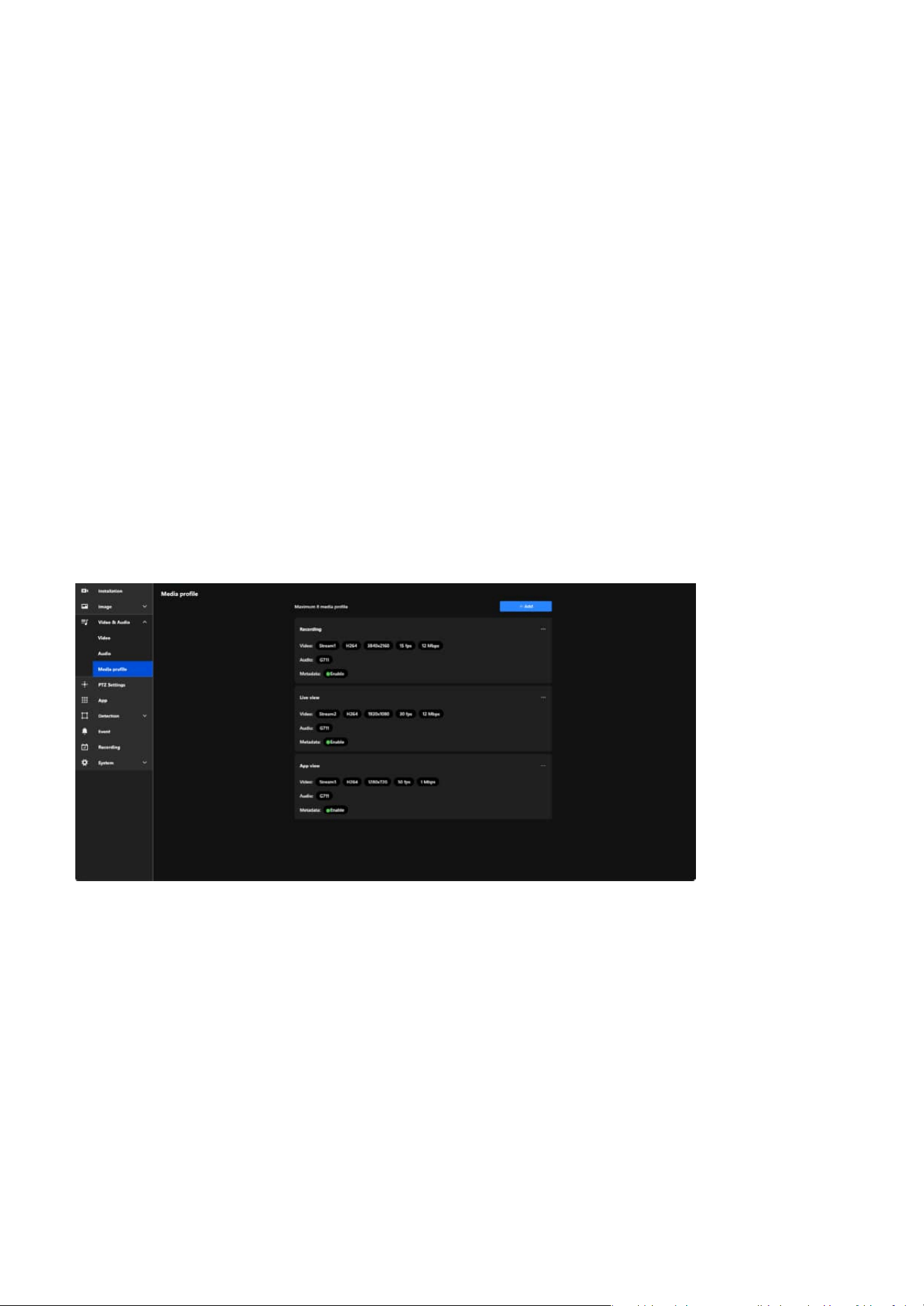
Configuring Media Profiles to Optimize Video
Performance for Versatile Applications
In VIVOTEK cameras, the Media Profile function primarily displays pre-set stream parameters and allows
users to enable or disable video, audio, and metadata. This functionality simplifies stream management
while providing the flexibility to adapt to various monitoring scenarios, such as recording, live viewing,
and mobile access, ensuring efficient and effective surveillance management.
• Record from camera
Use the camera's built-in microphone to record audio, with a maximum file size of 2MB.
• Upload a pre-recorded sound file
Upload a pre-existing audio file, which must be in .wav format and not exceed 2MB.
Step 2. Enter a name for the audio clip in the "Clip name" field (e.g., "Clips 01") to identify it later.
Step 3. In the "Waiting before recording" field, input the number of seconds to delay the start of the
recording (e.g., 5 seconds) to allow time for preparation before recording begins.
Step 4. Click the red "Start recording" button to initiate a countdown for the specified time, after which
the system starts recording audio and automatically saves the recording upon completion for
review.
Benefits and Features:
• Stream Management Simplified
Users can quickly enable or disable video, audio, and metadata features for each profile.
• Clear Stream Display
Media Profile displays the preconfigured stream parameters (e.g., resolution, frame rate, bit rate) for
easy identification and management.
• Flexible Application Scenarios
Users can create multiple profiles for different needs, such as:
• Recording: High-resolution video enabled.
• Live View: High frame rate for smooth real-time playback.
• App View: Low-resolution video for bandwidth efficiency.
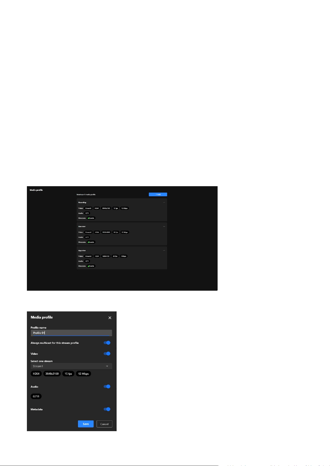
54
3 Video & Audio
Media profile
Steps to add a Media profile:
the Media profile is designed to display preconfigured stream parameters and allow users to enable or
disable specific features, such as:
• Video:
Displays the selected stream settings and allows enabling or disabling the video stream.
• Audio:
Enables or disables the audio feature and displays the audio codec in use.
• Metadata:
Enables or disables metadata functionality, supporting further video analysis and event tagging.
Note
Media Profile does not allow configuration of video resolution, frame rate, or bit rate. These parameters
are pre-set in the Stream settings, and Media Profile only displays the relevant settings and enables
feature toggling.
• Optimized Resource Management
By enabling or disabling features, users can reduce bandwidth and system resource usage as needed.

55
3 Video & Audio
Step 1. Locate and click the blue "+ Add" button on the Media Profile screen.
Step 2. To enter a profile name in the "Profile Name" field.
Step 3. Enabling the "Always Multicast for this Stream Profile" option allows multiple users to access the
same video stream simultaneously.
Note
This feature is particularly beneficial in scenarios requiring efficient data transmission, such as large-scale
surveillance systems. By utilizing multicast, the camera sends a single video stream that can be shared
among multiple viewers, significantly reducing network bandwidth consumption compared to unicast
streaming, where separate streams are sent to each user.
Step 4. To enable the "Video" option and select a stream in the Video stream settings.
Step 5. To enable the "Audio" option.
Step 6. To enable the "Metadata" option.
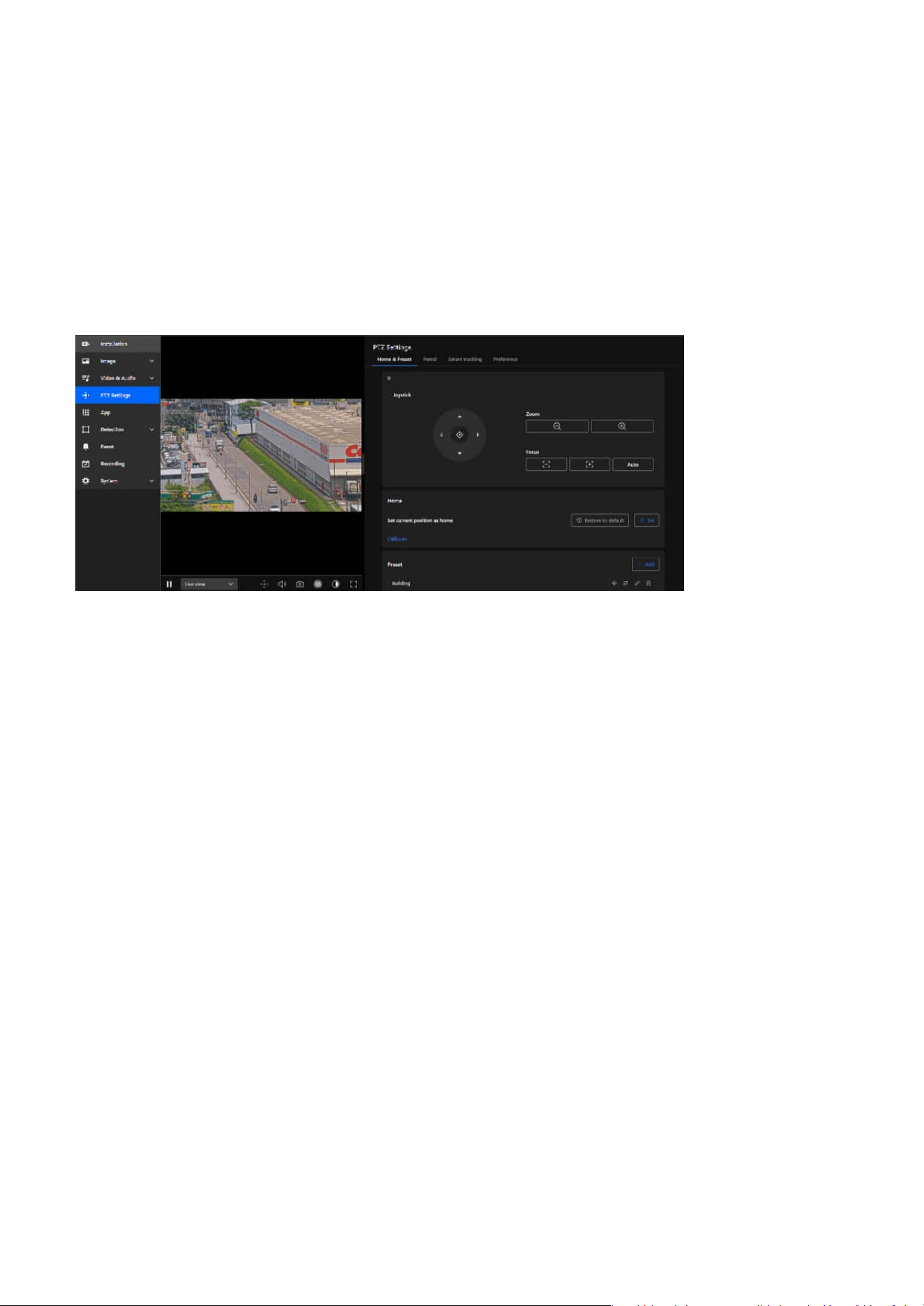
56
PTZ Settings
4
Effortlessly Manage and Customize PTZ Settings for
Precise Camera Control
Home & Preset
PTZ Settings is designed to provide users with a convenient interface for efficiently managing and
operating PTZ cameras, suitable for real-time adjustments and rapid targeting in surveillance scenarios,
enhancing the flexibility and accuracy of surveillance management.
PTZ Settings offers a comprehensive and intuitive set of tools for flexible operation of PTZ cameras,
covering real-time adjustments, preset management, and automated patrol. These features effectively
enhance surveillance efficiency, enabling users to quickly focus on critical details or meet the
requirements of large-scale scene monitoring.
The purpose of the Home & Preset tab in PTZ Settings is to assist users in configuring and managing the
primary viewpoints and preset positions of the camera, enhancing operational efficiency and enabling
quick transitions.
The purpose are as follows:
• Simplify Camera Operation
By configuring Home and Presets, users can quickly switch to and return to specified positions, reducing
the time required for manual adjustments.
• Enhance Surveillance Efficiency
Facilitates effective monitoring of multiple key areas, especially in scenarios that require frequent
perspective switching.
• Achieve Flexibility and Precision
Enables users to precisely configure and adjust the camera's viewpoints and focal lengths to meet the
demands of various scenarios.
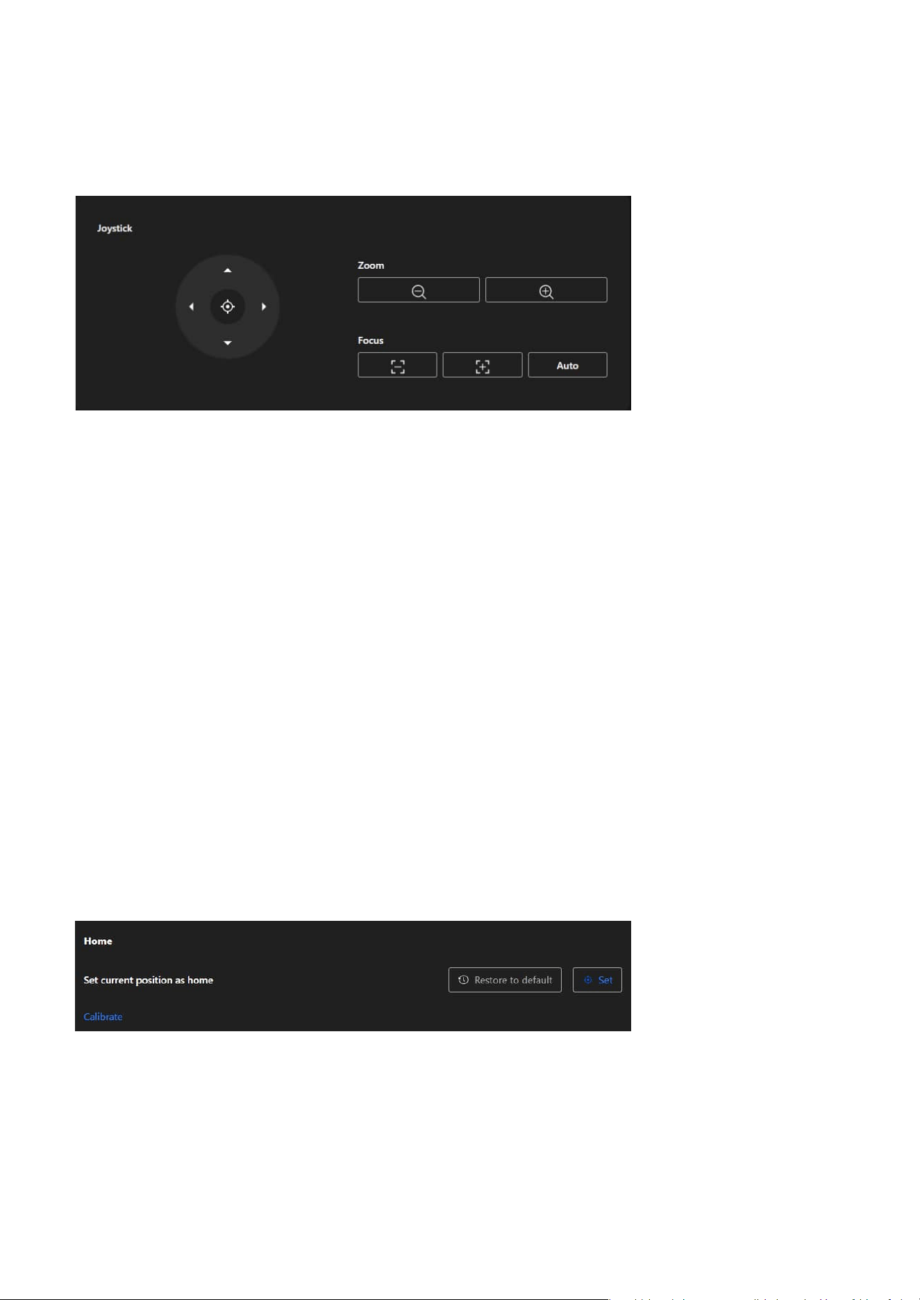
57
4 PTZ Settings
Joystick
Home
The Home enables users to set and restore the camera's baseline viewpoint, aiming to improve
operational efficiency, simplify camera management, and ensure the stability and flexibility of the
monitoring process.
Direction Control
• Provides a virtual joystick with directional buttons for up, down, left, and right, enabling users to
operate the camera's pan and tilt in real time.
•
Clicking the directional arrows moves the camera in the corresponding direction.
Center Positioning
The central button can be used to quickly reset or reposition the camera to its current center point or
initial position.
Zoom Control
• Zoom Out: Reduces the zoom level, expanding the camera's field of view.
• Zoom In: Increases the zoom level, focusing on details or specific targets.
Focus
• Manual Focus Adjustment: Users can fine-tune focus manually.
• Auto Focus: The camera automatically adjusts focus for optimal clarity.
The Joystick provides users with precise control over the camera's direction and focus, suitable for real-
time operation, ensuring flexibility and accuracy in the monitoring range.
Set Current Position as Home
By pressing the Set button, users can designate the camera's current viewpoint (direction and zoom) as
the Home position, serving as the default baseline.
Restore to Default
By pressing the Restore to Default button, the camera's Home position will be reset to its factory settings
or the predefined default position.
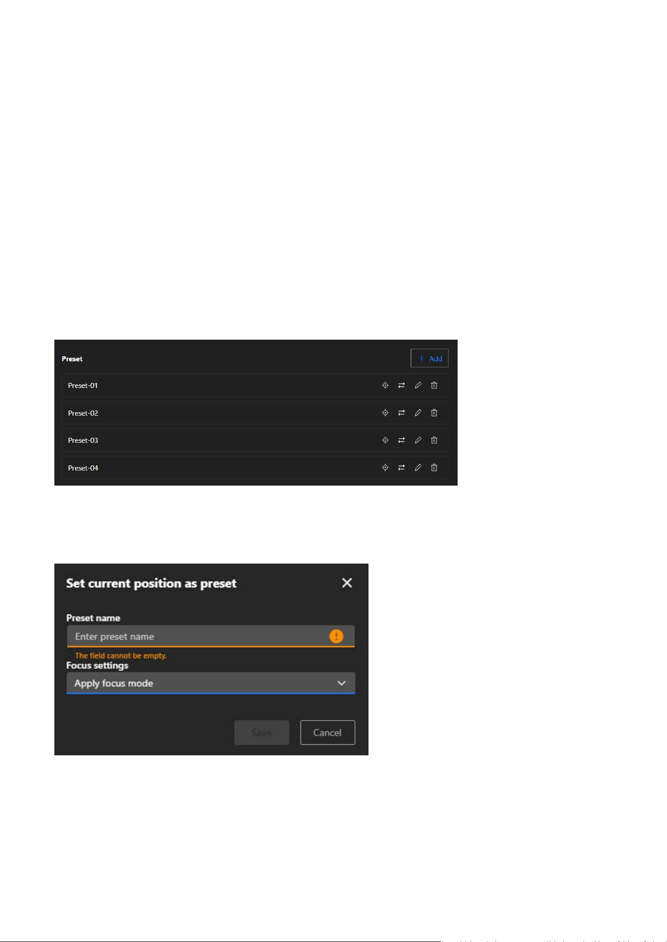
58
4 PTZ Settings
Preset
Add Preset
By using the + Add button, users can save the camera's current viewpoint (direction and zoom) as a new
preset, enabling quick access to that position in the future.
The Preset allows users to easily manage multiple surveillance viewpoints of the camera, aiming to
simplify operations, enhance efficiency, and meet the needs of flexible monitoring in various scenarios.
Calibrate
This function recalibrates the camera’s home position to its default center to correct any displacement
caused by external forces. Calibration takes effect immediately without a confirmation message. Use this
function when the camera’s pan or tilt movement no longer aligns accurately with the expected field of
view due to extended use or physical disturbance. Recalibration restores the original coordinate system
to ensure precise PTZ control.
After calibration:
• The camera returns to the default home position, or to a user-defined home if one is configured.
• Preset positions are correctly aligned based on the updated pan and tilt coordinates.
• The calibration process does not trigger motion detection.
Preset List
Saved presets are displayed in a list format (e.g., Preset 01 and Preset 02). Users can perform the following
actions for each preset:
• Set as Home
Assign the current preset as the Home position (via the target icon), making it easy to return to that
point.
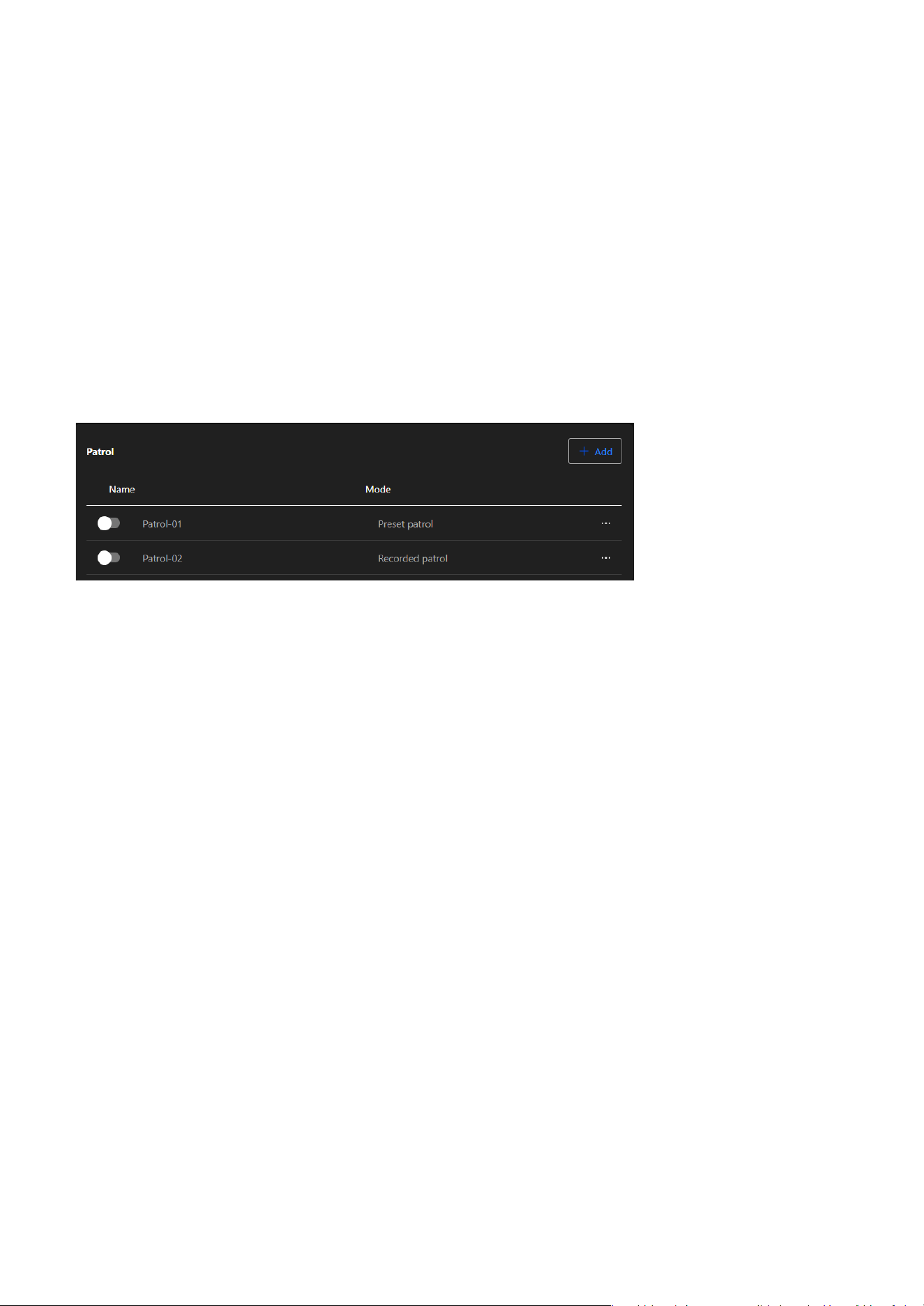
59
4 PTZ Settings
Patrol
The purposes are as follows:
• Achieving Automated Patrol
Through predefined patrol routes, the camera can automatically move sequentially to different
surveillance points, ideal for large-scale or multi-area monitoring needs.
• Reducing Manual Operations
The automation feature eliminates the need for frequent manual control, enhancing monitoring
efficiency and saving manpower.
• Adapting Flexibly to Scene Requirements
Customizable patrol routes and multi-mode support allow the system to adapt to dynamic scenarios or
diverse surveillance targets.
• Enhancing Security
By regularly patrolling all preset points, the system ensures that every critical area is monitored in a
timely manner, reducing the risk of blind spots in surveillance.
Add Patrol Route
Click the “Add” button and choose one of the following patrol types:
The Patrol feature utilizes automated patrol routes to enable the camera to efficiently cover multiple
surveillance points, reducing manual intervention and achieving comprehensive and flexible monitoring
management.
• Update Preset Position
Assign the current camera view to the selected preset by clicking the arrow icon. This will update the
preset with the new position.
• Edit
Modify the name or the focus of the preset.
• Delete
Remove presets that are no longer needed.
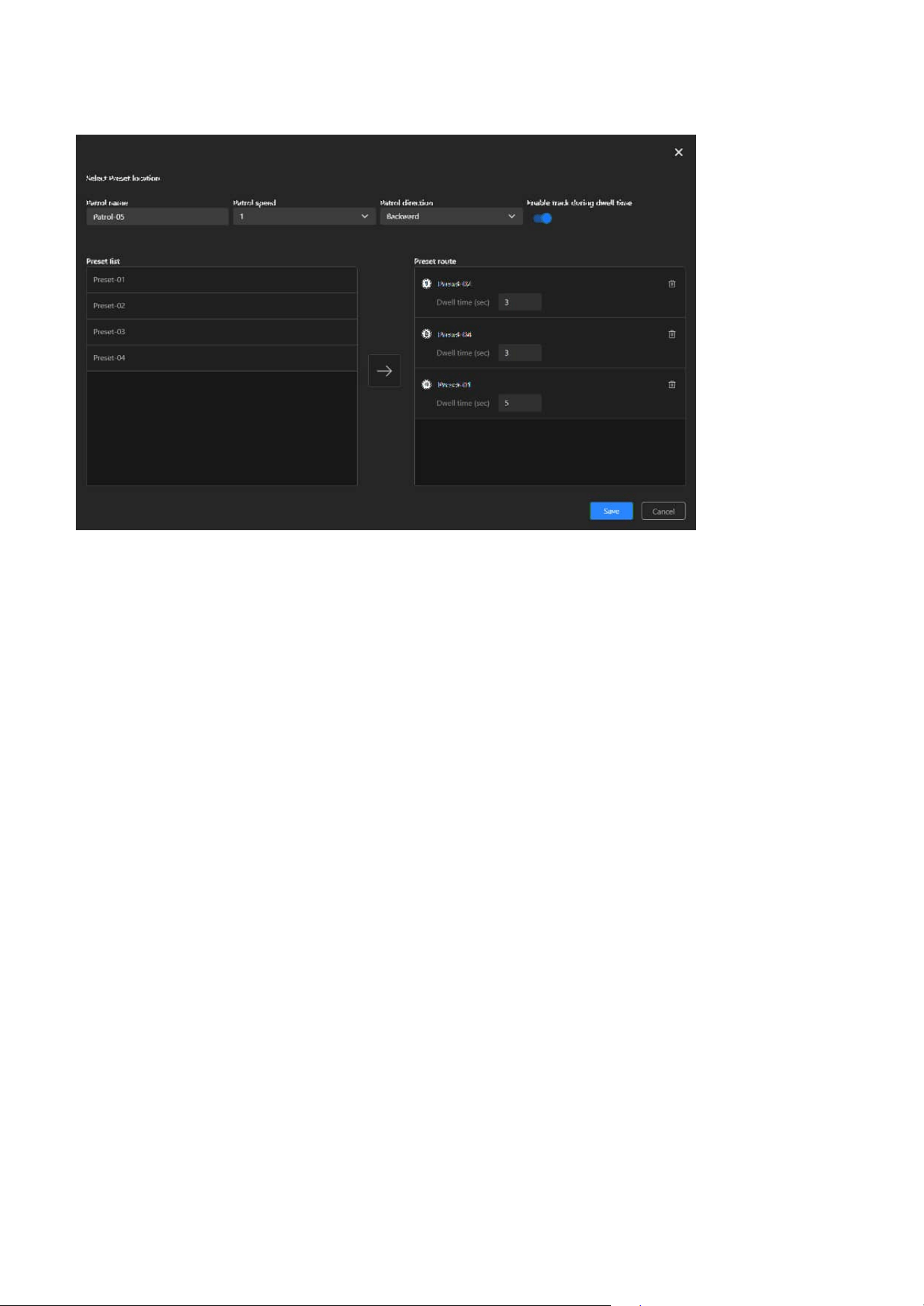
60
4 PTZ Settings
Preset Patrol
Step 1. Select “Preset patrol”
Begin creating a patrol route by selecting “Preset Patrol.”
Step 2. Set Patrol Parameters
Enter a name for the patrol route and configure the patrol speed and direction.
Step 3. Select Preset Points
The Preset List on the left displays the configured preset points. Browse the list and select the
points you want to include in the patrol route.
Step 4. Add to Patrol Route
After selecting a preset point on the left, click the arrow "
→
" in the middle to add it to the Preset
Route list on the right.
Step 5. Set Dwell Time for Each Preset Point
In the Preset Route list, assign a dwell time (in seconds) for each added preset point. The dwell
time can range from 1 to 999 seconds, adjusted based on monitoring needs.
Step 6. Adjust Patrol Order
To change the patrol order of preset points, adjust their positions in the list on the right (drag,
or delete and re-add them). Remove extra preset points: Click the Trash Can button next to the
preset point.
Step 7. Save the Route
After confirming all preset points, dwell times, and order, click the Save button in the lower-right
corner to save the route.
Step 8. Activate Patrol Mode
Return to the Installation panel and go to PTZ tab. In the Patrol dropdown menu, select the
desired patrol route to activate it. To stop the patrol, click the “Stop” button under the Pan & Patrol
control section.
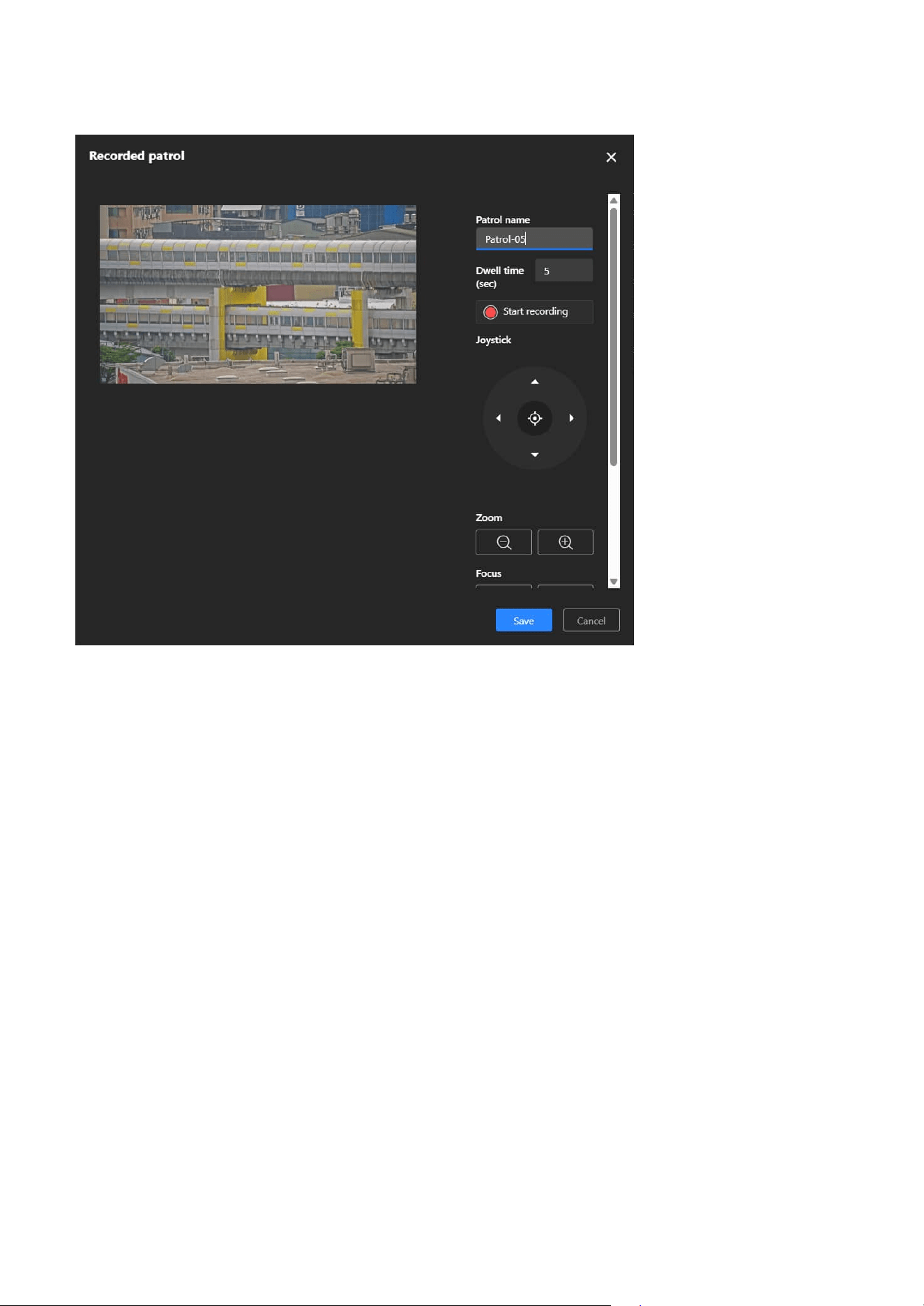
61
4 PTZ Settings
Step 1. Select "Recorded Patrol"
Choose Recorded Patrol to define a route by manually operating the PTZ controls during
recording.
Step 2. Set Patrol Parameters
Enter a name for the patrol route and set the dwell time.
Step 3. Record Patrol Path
Click “Start recording.” Use the PTZ joystick to move the camera along the desired path. The
system records the movements and speed in real time.
Step 4. Save the Patrol
Click “Save” to store the recorded route.
Step 5. Activate Patrol
Return to the Installation panel and go to PTZ tab. In the Patrol dropdown menu, select the
desired patrol route to activate it. To stop the patrol, click the “Stop” button under the Pan & Patrol
control section.
Recorded Patrol
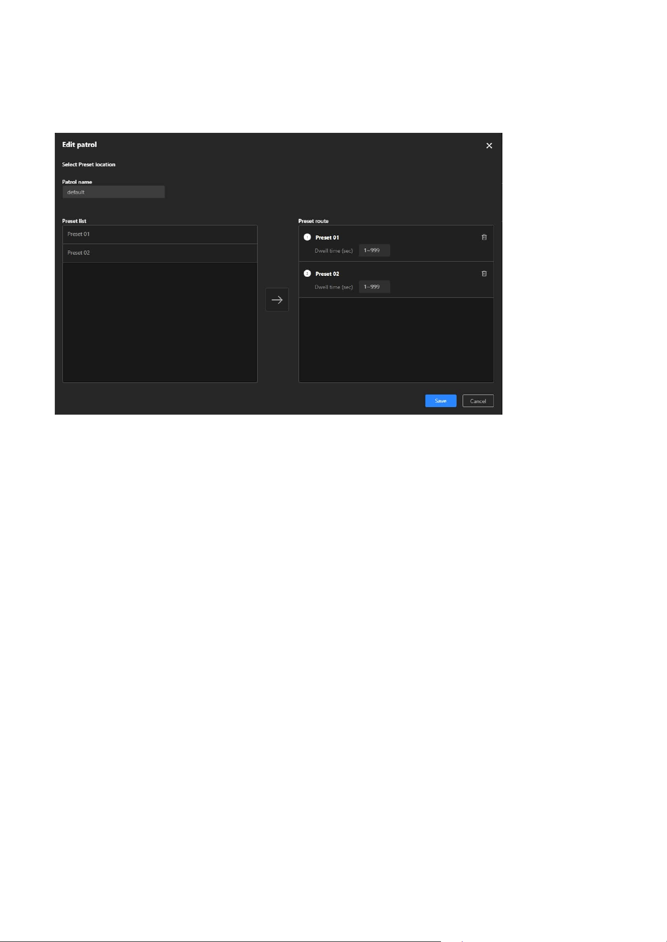
62
4 PTZ Settings
Smart Tracking
Step 2. Select Preset Points
The Preset List on the left displays the configured preset points. Browse the list and select the
points you want to include in the patrol route.
Step 3. Add to Patrol Route
After selecting a preset point on the left, click the arrow "
→
" in the middle to add it to the Preset
Route list on the right.
Step 4. Set Dwell Time for Each Preset Point
In the Preset Route list, assign a dwell time (in seconds) for each added preset point. The dwell
time can range from 1 to 999 seconds, adjusted based on monitoring needs.
Step 5. Adjust Patrol Order
To change the patrol order of preset points, adjust their positions in the list on the right (drag,
or delete and re-add them). Remove extra preset points: Click the Trash Can button next to the
preset point.
Step 6. Save the Route
After confirming all preset points, dwell times, and order, click the Save button in the lower-right
corner to save the route.
Step 7. Activate Patrol Mode
Return to the Installation panel and go to PTZ tab. In the Patrol dropdown menu, select the
desired patrol route to activate it. To stop the patrol, click the “Stop” button under the Pan & Patrol
control section.
Edit Patrol Route
Step 1. Click “More” icon > “Edit” button
Click the Edit button on the right side of the existing route.
Smart Tracking Advanced is an AI-driven auto-tracking technology in VIVOTEK PTZ cameras. It enhances
traditional tracking capabilities by using intelligent object recognition to detect and follow humans and
vehicles in real time. This feature ensures that critical targets remain in focus, reducing manual monitoring
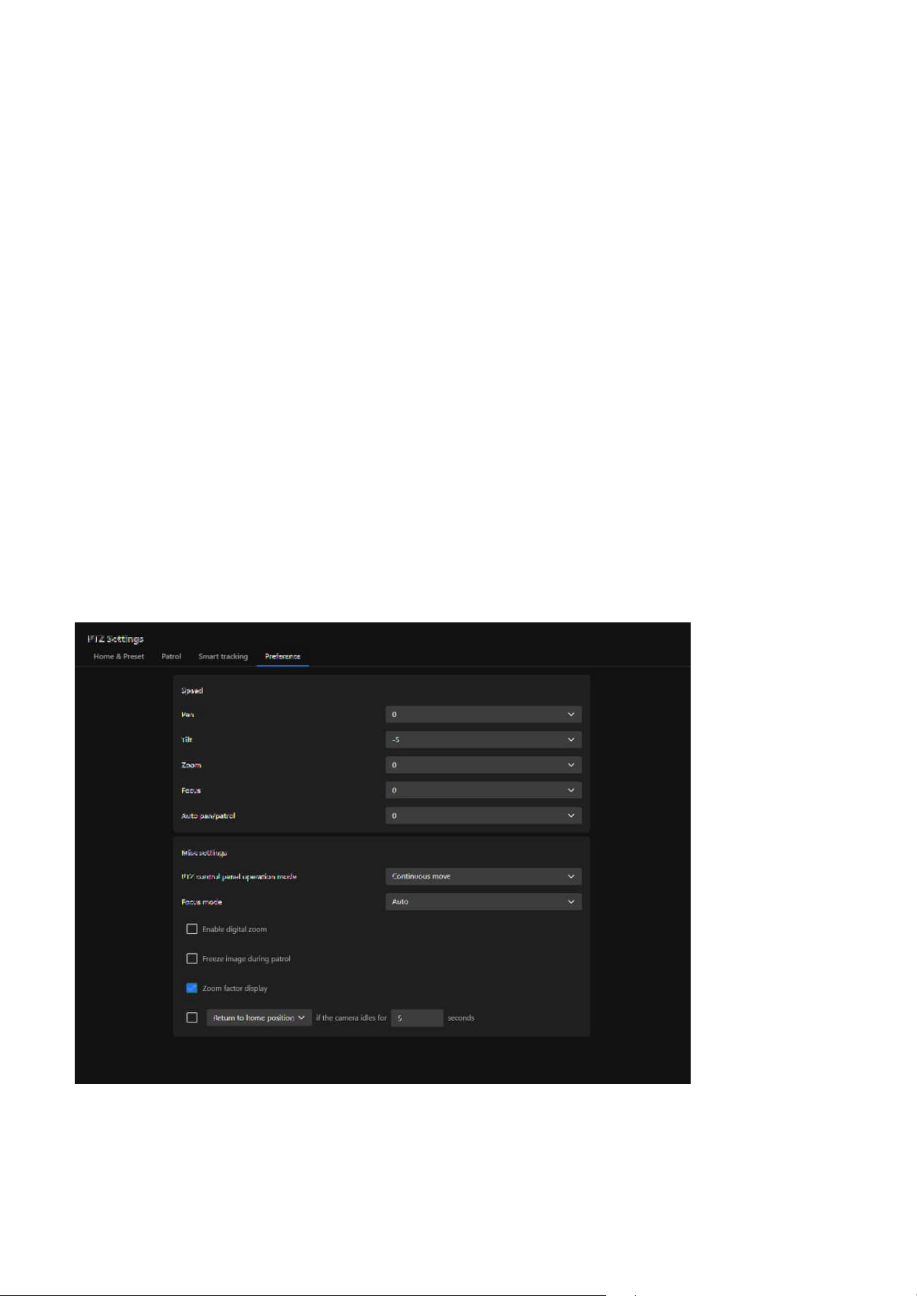
63
4 PTZ Settings
Preference
The Preference tab allows users to adjust PTZ speed settings, select control and focus modes, and
configure options such as digital zoom, zoom factor display, and idle-time behavior. These settings
provide flexibility in camera operation, supporting more efficient and accurate surveillance management.
efforts and improving surveillance efficiency.
• AI-Powered Object Recognition
Differentiates between humans and vehicles to reduce false tracking.
• Automated PTZ Tracking
Locks onto moving objects and keeps them in view.
• Flexible Trigger Conditions
Can be activated by intrusion, loitering, or line crossing events.
• Enhanced Surveillance Efficiency
Reduces manual intervention and automates monitoring.
• Ideal for Large-Scale Monitoring
Suitable for airports, malls, parking lots, and perimeter security.
With Smart Tracking, cameras can intelligently detect and track people or vehicles, offering a more
efficient and automated security solution.
Note
A simple setup guide can be found in the Detection > Smart Tracking Advanced section.
The purposes are as follows:
• Enhancing Operational Flexibility
Different scenarios may require different speed settings. By adjusting pan, tilt, and zoom speeds, users
can achieve more precise control of the camera.
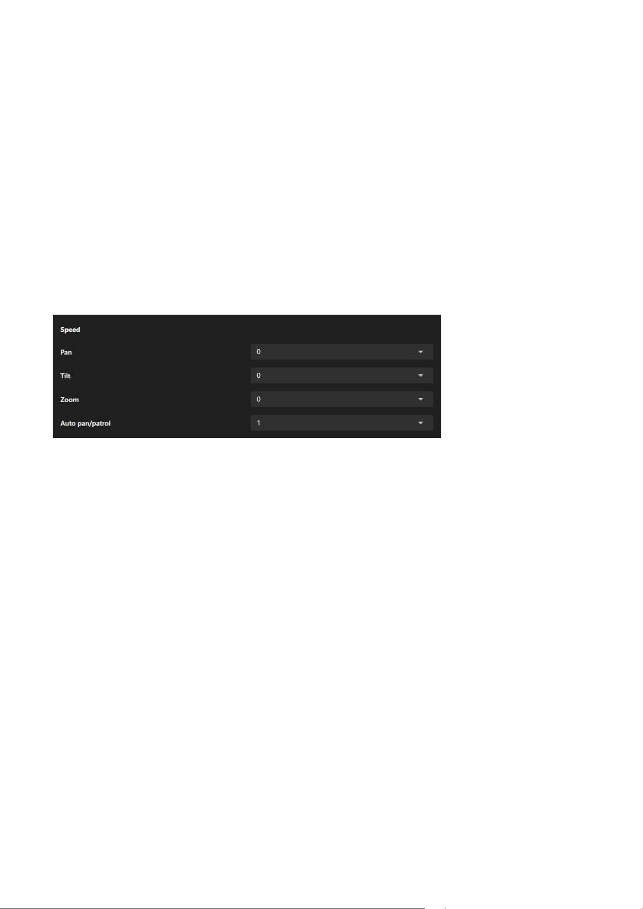
64
4 PTZ Settings
Speed
Misc settings
Pan (Horizontal Panning Speed)
Controls the speed at which the camera moves left and right.
Tilt (Tilting Speed)
Adjusts the speed at which the camera moves up and down.
Zoom (Zooming Speed)
Configures the speed at which the lens zooms in and out. Ideal for quickly focusing on details or slowly
zooming to maintain a smooth transition.
Focus (Focusing Speed)
Adjusts the speed at which the camera fine-tunes its focus. A higher speed allows faster adjustments
when the scene changes quickly, while a lower speed provides more precise focusing for detailed
observation.
Auto Pan Speed (Automatic Panning Speed)
Sets the movement speed of the camera in auto-panning mode. Enables users to adjust the speed to suit
surveillance needs, such as faster coverage for large areas or slower movement for observing details.
The Speed provides comprehensive control over the camera's movement speed, including pan, tilt, zoom,
and automated patrol, allowing users to flexibly adjust the speed based on surveillance needs for precise
and efficient camera operation.
The Misc Settings section provides additional configuration options, including control and focus modes, as
well as display options such as digital zoom, freeze image during patrol, zoom factor display, and camera
idle-time action.
• Adapting to Diverse Surveillance Needs
In patrol mode or manual operation, users can set appropriate automatic movement and zoom speeds
based on the importance of the scene or the speed of moving targets.
• Improving Surveillance Accuracy
The zoom level display feature allows users to clearly understand the current magnification, making it
suitable for surveillance scenarios that require focusing on details.
• Simplifying Personalized Settings
Users can configure parameters that align with their operational preferences, enhancing overall
efficiency.
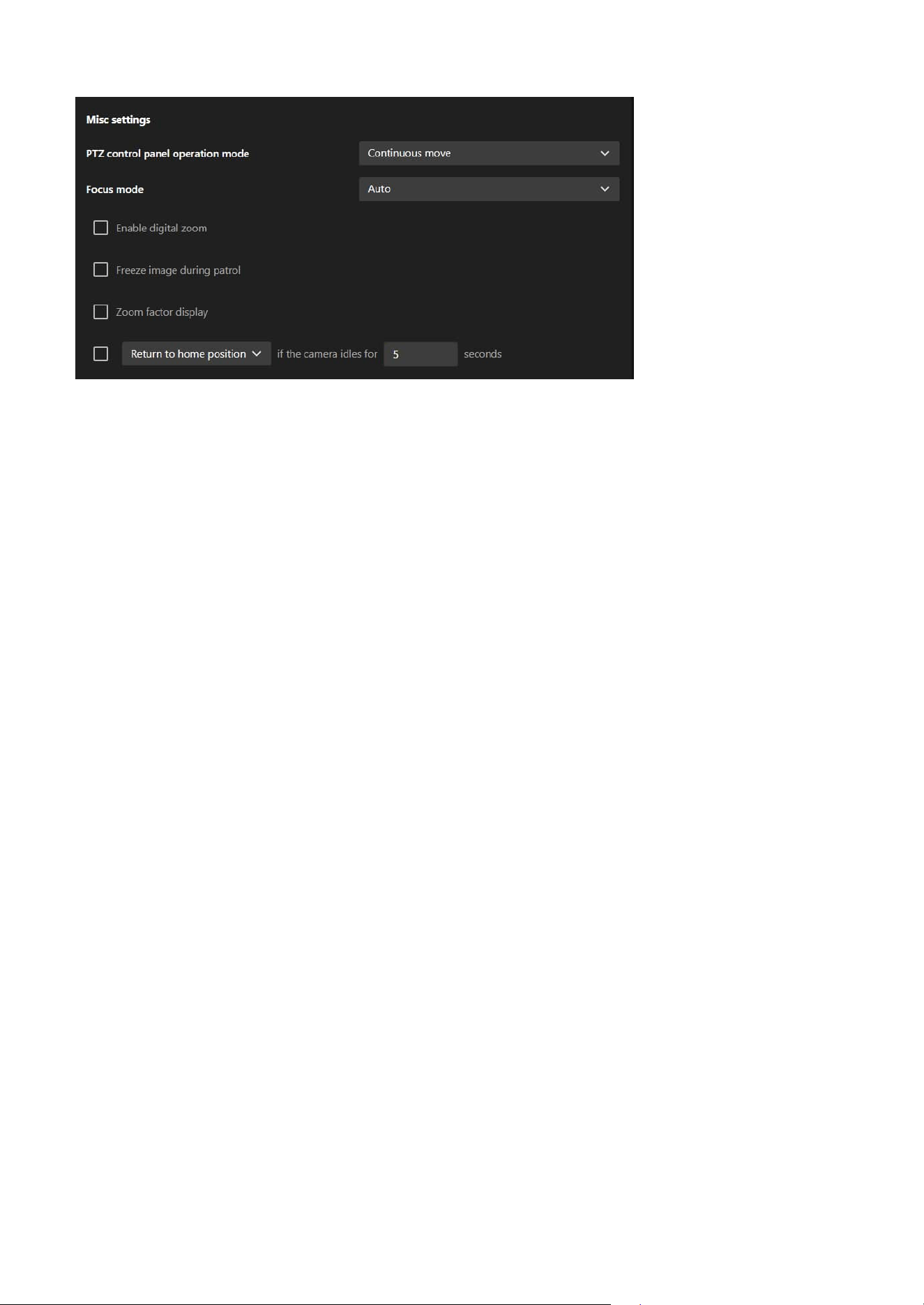
65
4 PTZ Settings
Focus Mode
This setting determines how the camera adjusts focus when moving to different areas, preset points, or
zoom levels.
• Auto
The camera automatically adapts to varying object distances and lighting conditions to achieve optimal
focus. The autofocus function also utilizes object information from Smart Tracking, enabling the camera
to maintain a sharper focus on the tracked subject.
• One-time Focus
Focus is performed once when the camera moves to a preset point. This avoids repeated focusing that
may occur due to moving objects in the scene. It is suitable when a consistent depth of field is preferred
and minimal focus adjustment is desired after movement.
• Manual
Focus must be manually adjusted after the camera moves to a new position. This mode is also suitable
for use with third-party intelligent video analytics software that utilizes an independent focusing
algorithm, in which case the other focus modes do not apply.
PTZ Control Panel Operation Mode
This setting determines how the mouse and PTZ control panel behave in the live view window.
• Continuous Move
The camera continues moving in the selected direction while the left mouse button is held down.
For example, clicking and holding the left directional button on the PTZ panel causes the camera to
continuously pan left until the button is released. The same behavior applies to the directional buttons,
as well as the Zoom and Focus controls.
• Click to Move
Each click performs a single movement or action. Holding the button does not result in continuous
motion.
Enable Digital Zoom
If this option is selected, digital zoom up to 4× is available in addition to the 30× optical zoom, allowing
further magnification of the image. When digital zoom is enabled, the Electronic Image Stabilization (EIS)
function will be disabled automatically.
Freeze Image During Patrol
When enabled, this option hides the transition process between preset points during a patrol. Only the
final view at each preset point is displayed.
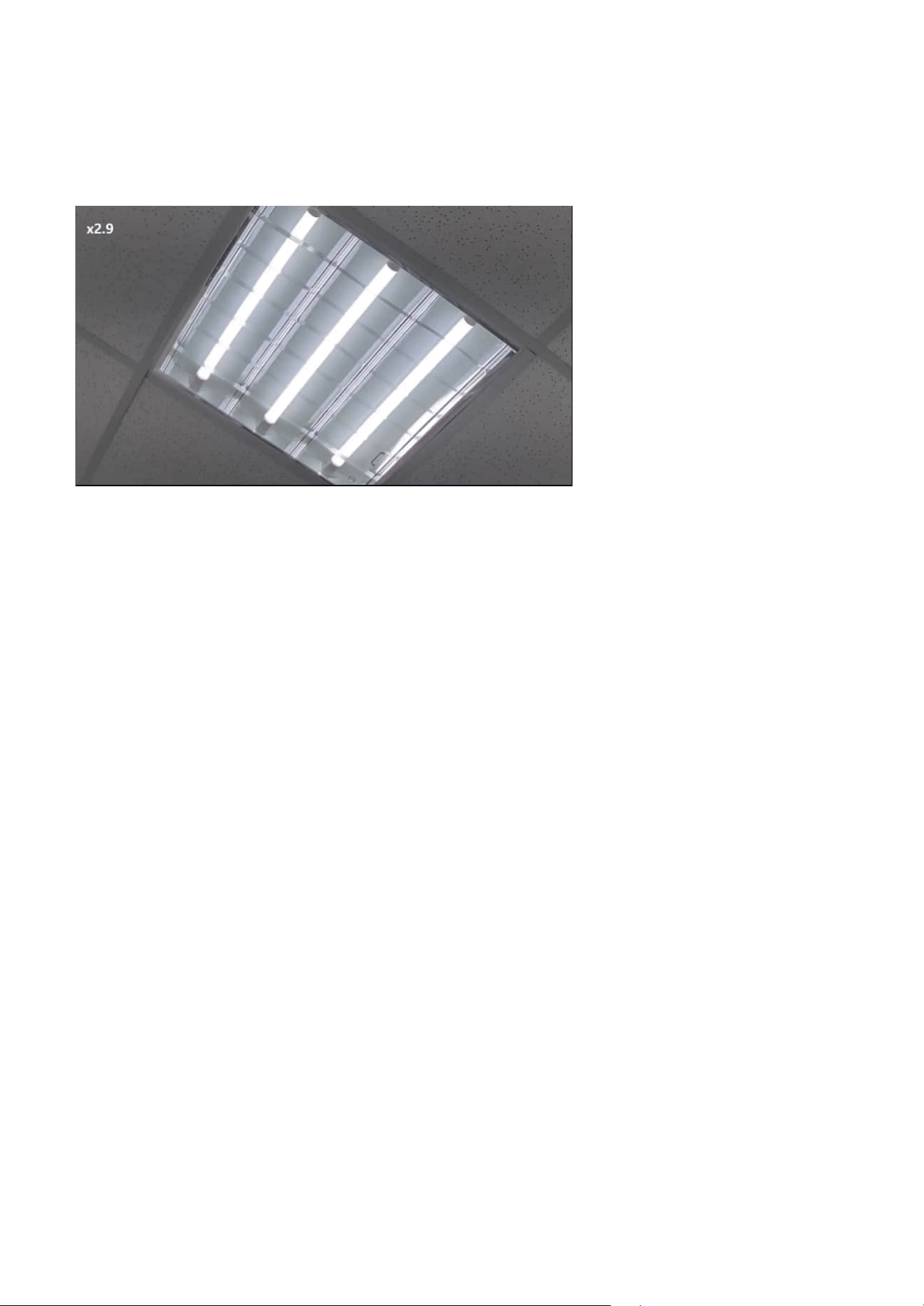
66
4 PTZ Settings
Idle-Time Action
This setting defines the action to be taken when the camera remains idle for a specified period (1–999
seconds). The idle state excludes ongoing pan, patrol, or tracking operations.
Available actions include:
• Apply Previous Action
Resumes the previous action (auto pan, patrol, stop, or auto tracking) after the camera remains idle for
the specified duration.
• Enable Track
Enables auto tracking mode after the idle period.
• Return to Home Position
Moves the camera back to its defined home position when no user activity occurs during the configured
time.
• Start to Pan
Initiates automatic panning when the camera is idle.
• Start to Patrol
Resumes the patrol tour from the last visited preset point.
Zoom Factor Display
When this option is selected, the system will display the current zoom factor whenever the camera's
zoom function is used. The zoom factor is typically presented in numerical form, allowing users to easily
understand the current magnification level of the lens.
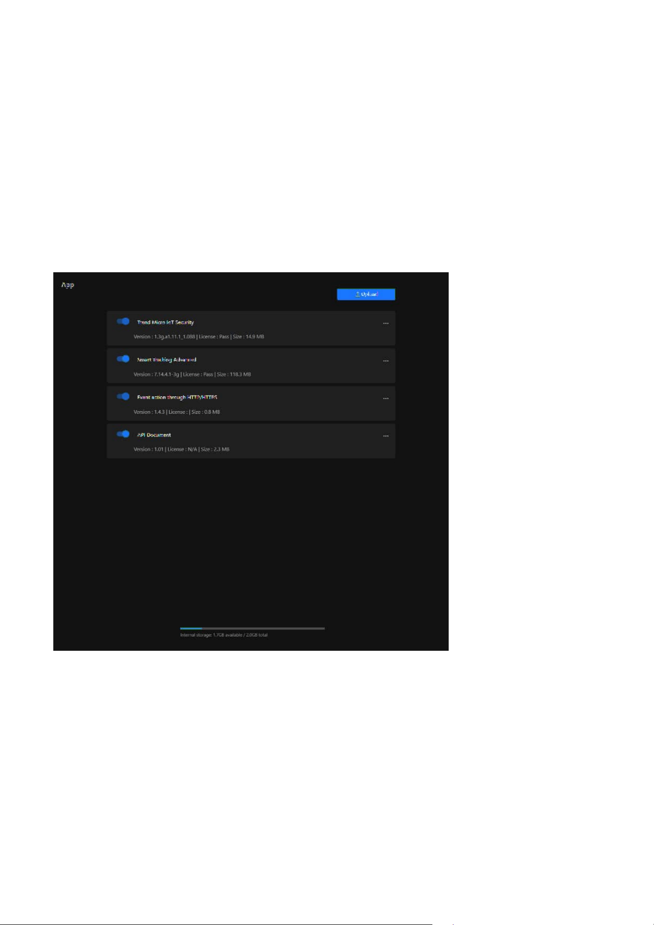
67
App
5
Expand Camera Functionality with Powerful Applications
Trend Micro IoT Security
The App feature provides users with a centralized platform for managing, installing, and updating
applications on the camera, aiming to enhance the device's flexibility, security, and functionality, enabling
it to adapt to diverse surveillance scenarios and requirements.
A security application provided by Trend Micro, designed specifically for IoT devices. Its main functional
purposes are as follows:
• Enhance Camera Security
Protects the camera from network attacks that may disrupt its operation.
• Safeguard Data Privacy
Ensures the security of video data and settings, preventing unauthorized access.
• Reduce Maintenance Costs
Minimizes device failures or data loss caused by security issues.

68
5 App
Event action through HTTP/HTTPS
API Document
Smart Tracking Advanced
The main purpose of this feature is to enable smart automation and integration with external systems.
Specific use cases include:
• Notifications & Alerts
When an event occurs, the camera can send an HTTP/HTTPS request to a specified server or API, such
as:
• Sending an alert to a monitoring center
• Triggering third-party systems (e.g., NVR, VMS, or cloud platforms)
• Reporting events to IoT or SCADA systems for further automation
• Triggering Other Systems
It can trigger other smart devices or systems, such as:
• Opening or closing access control systems
• Activating alarms or warning lights
• Notifying AI analytics systems for further processing
• Integration with Third-Party Applications
Allows integration with enterprise or cloud-based APIs, such as:
• Sending data to a RESTful API for event logging
• Integrating with cloud-based smart surveillance platforms
• Triggering scripts for automation control
An AI-based auto-tracking application designed to enhance PTZ camera performance by intelligently
detecting and tracking moving targets in real time. Its main functional purposes are as follows:
• Enhance Tracking Accuracy
Differentiates humans and vehicles to reduce false tracking and improve target identification.
• Automate PTZ Control
Performs automatic pan, tilt, and zoom actions to follow moving objects without manual input.
• Support Event-Based Activation
Enables real-time tracking triggered by events such as intrusion, loitering, or line-crossing detection.
Note
A simple setup guide can be found in the Detection > Smart Tracking Advanced section.
An interactive interface that enables developers and system integrators to access, test, and integrate
camera features using standard API commands. Its main functional purposes are as follows:
• Support System Integration
Allows third-party platforms, such as VMS or cloud systems, to control camera functions through API
requests.
• Facilitate Feature Access
Enables remote access to advanced features—such as preset control, stream configuration, and
certificate management—without using the camera's native UI.
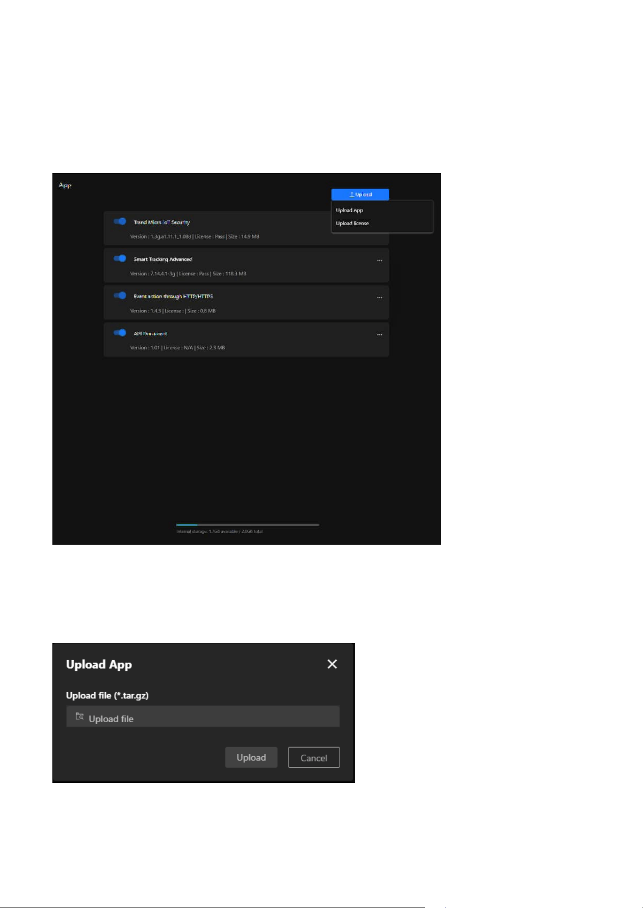
69
5 App
Steps to Upload App
Step 1. Click the “Upload” button in the upper-right corner of the page. Two options will appear:
• Upload App: For uploading application files.
• Upload License: For uploading application license files.
• Provide Interactive Testing
Offers a user-friendly interface for issuing API calls and viewing real-time responses, helping verify
integration logic and reduce development time.
Note
The API Document is not pre-installed on the camera. It must be downloaded separately from the SDK
page on the official website.
Step 2. Click Upload App, and a file upload window will pop up. The accepted file format is .tar.gz.
Step 3. Click Upload file and select the application file stored on your local device.
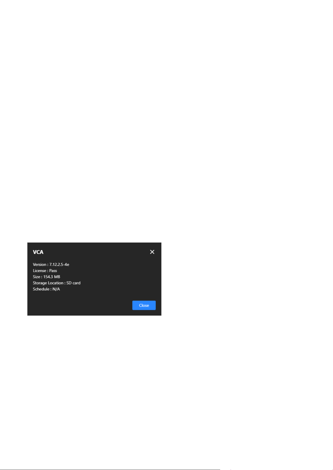
70
5 App
Steps to Upload License
Step 1. Click the Upload button in the upper-right corner of the page. Two options will appear:
• Upload App
For uploading application files.
• Upload License
For uploading application license files.
Step 2. Click Upload License, and a file upload window will pop up. The accepted file format is *.xml.
Step 3. Click Upload file and select the appropriate license file.
Step 4. After verifying the file, click Upload to upload the license.
Step 5. Wait for the Upload to Complete
Step 6. A “Upload successfully” message appears.
Each application's More icon (click the three-dot icon on the right) provides the following features and
purposes:
Information
Monitor Application Status helps users quickly understand application details, ensuring the version and
license are accurate, while also assisting in troubleshooting by providing essential information like version
and license to diagnose issues effectively.
Schedule
Configure the application's runtime schedule to specify when it should be enabled or disabled and
set specific time periods to conserve resources or meet different scenario requirements. This feature
optimizes resources by preventing unnecessary long-term application operation, conserving processing
power, and adapts to various scenarios by automating application start and stop, enhancing flexibility.
Delete
Free up storage by removing unneeded applications, especially when storage is limited, and adjust
functionality by deleting unused or expired applications to make room for new installations.
Step 4.
After verifying the file, click Upload to upload the application.
Step 5. Wait for the Upload to Complete.
Step 6. The system will display the upload progress. Once completed, the application or license file will
appear in the App list.
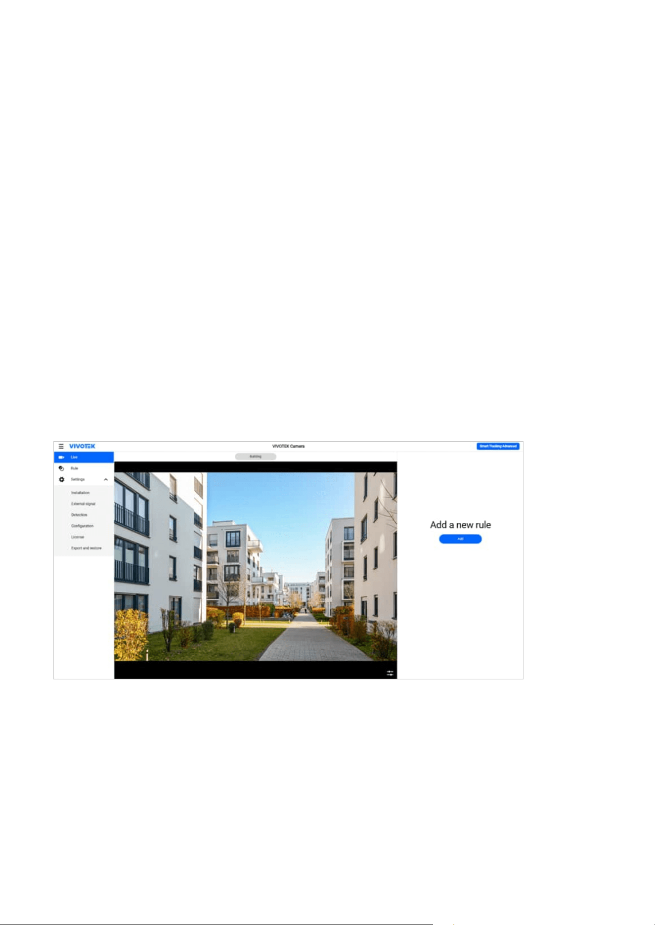
71
Detection
6
AI Auto-Tracking for Easy and Accurate Monitoring
Smart Tracking Advanced
The purpose of the Detection is to enhance the automated monitoring capabilities of the camera,
reduce manual intervention, and promptly notify relevant personnel in the event of anomalies, thereby
improving security and efficiency. Users can enable and configure the corresponding detection options in
the management interface based on specific needs.
Smart Tracking is an AI-powered auto-tracking feature in VIVOTEK PTZ settings, designed to detect and
follow moving people or vehicles. This allows the camera to automatically lock onto and track targets,
enhancing surveillance efficiency.
Set up Smart Tracking:
Step 1. Open Smart Tracking Settings
1. Access the Detection > Smart Tracking Advanced.
Step 2. Select a Preset Point (Tracking Start Point)
1. Choose a preset point (Preset) as the reference point where Smart Tracking will be triggered.
2. This preset position serves as the starting point for tracking movements.
Step 3. Configure Trigger Rule
1. Select the detection type that will trigger Smart Tracking.
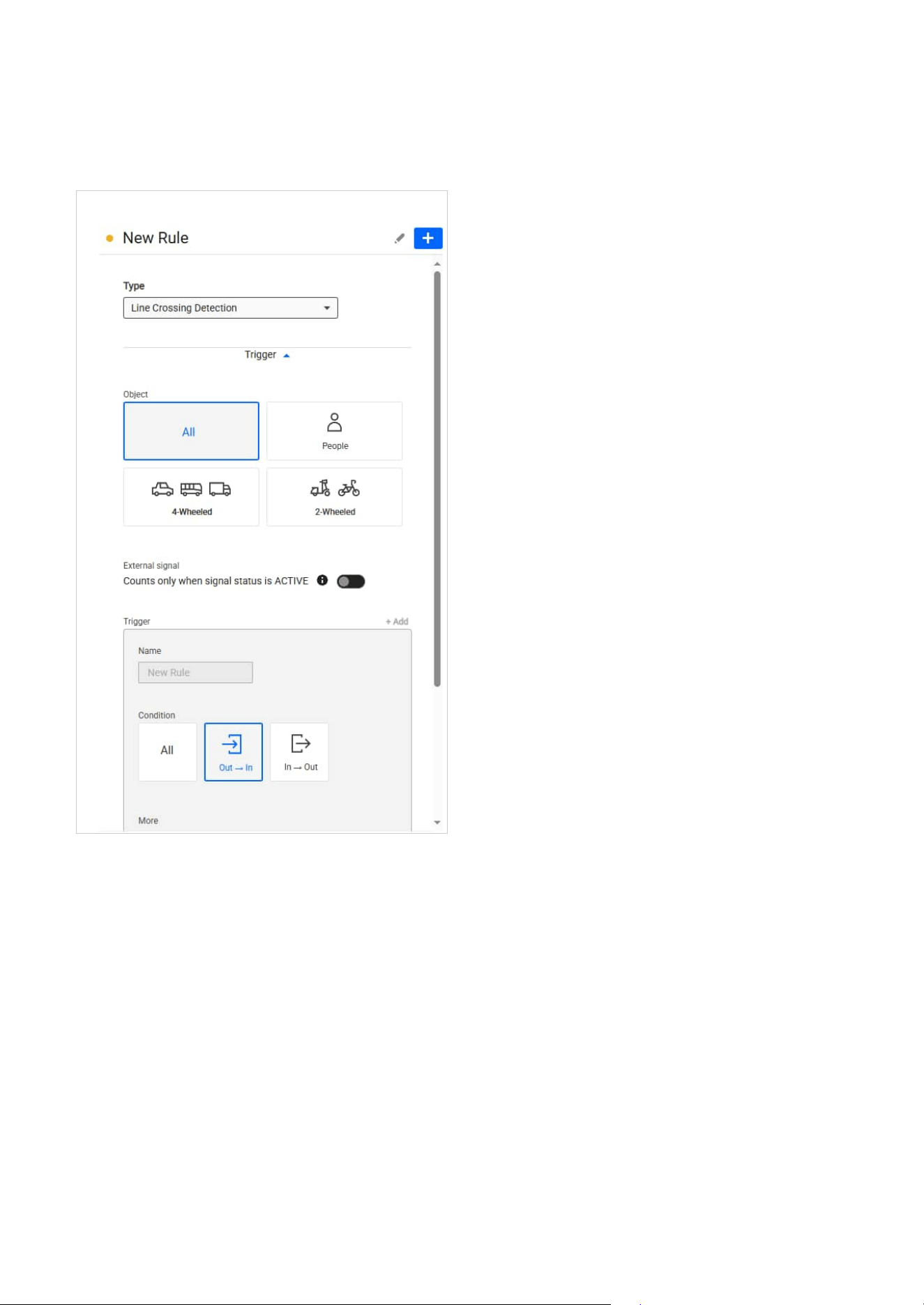
72
6 Detection
Note
Before configuring, ensure that the camera height has been calculated or entered manually. For detailed
setup information and procedures, refer to the Smart Tracking Advanced User Manual.
2. Set up the trigger conditions.
3. Configure the tracking action.
4. Set up the tracking schedule.
Step 4. Save and Activate Smart Tracking
1. Click “Save” to apply the settings.
2. Once enabled, the camera will automatically initiate tracking when the trigger conditions are
met.
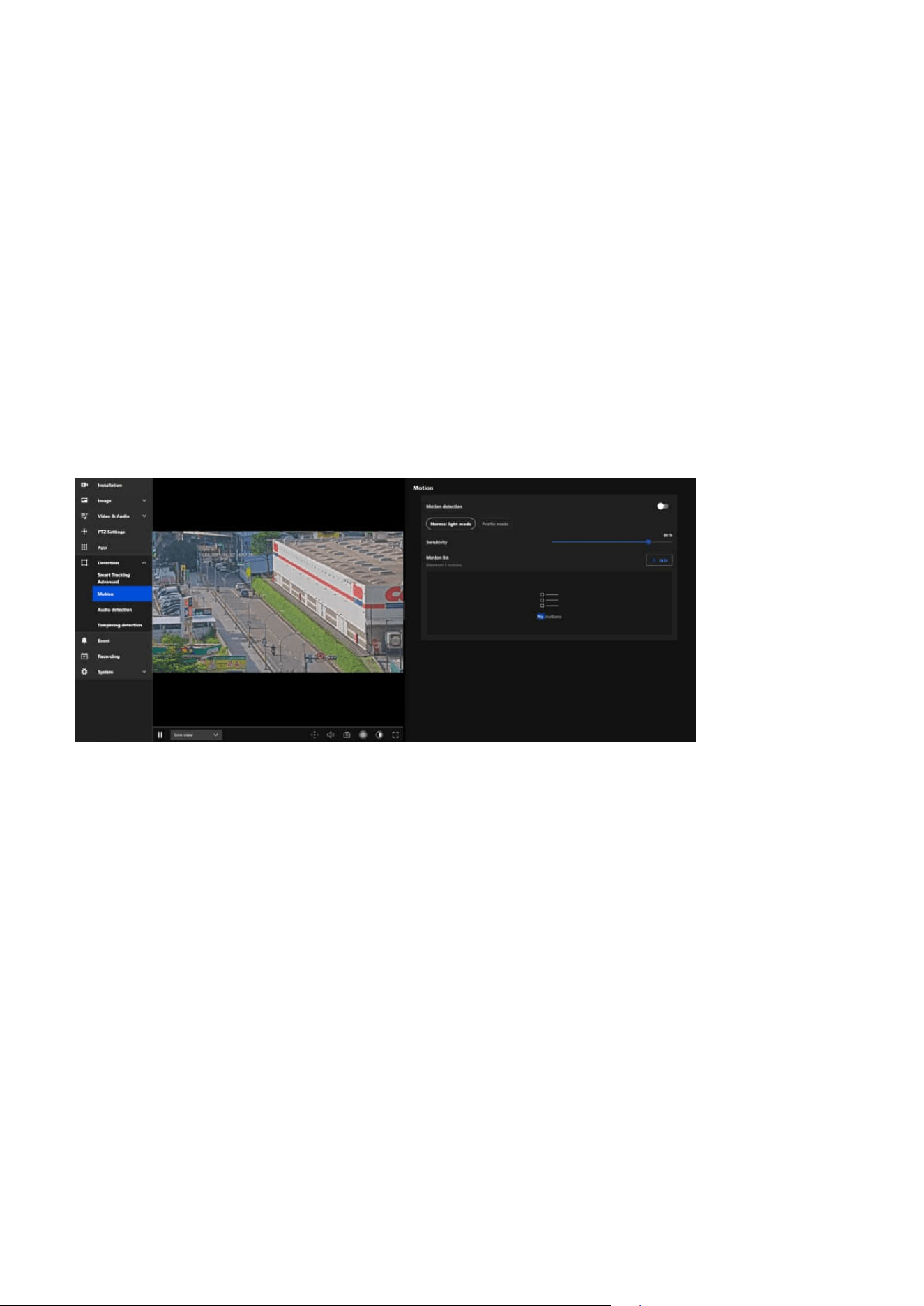
73
6 Detection
Motion
Instantly Detect Suspicious Activity and Intrusions with
an Intelligent Surveillance System
Benefits of This Feature:
• Instantly detect abnormal movement or intrusion
• Trigger automatic recording, alerts, or system actions
• Reduce false alarms through customizable sensitivity and zones
• Minimize manual monitoring effort and improve response time
•
Apply different detection logic based on lighting or time profiles
VIVOTEK’s Motion Detection function enables the camera to automatically monitor visual changes within
its field of view. When movement is detected, the system can trigger predefined actions such as video
recording, alerts, or notifications—ensuring real-time security responses and reducing the need for
constant manual monitoring. This feature is ideal for environments such as retail stores, offices, and
warehouses, where rapid awareness of abnormal events is critical.
Motion Detection analyzes the camera’s video stream and identifies visual changes caused by moving
objects. When movement occurs in a defined detection zone, it triggers an event. This can be linked to
various actions for intelligent automation and enhanced security monitoring.
How to Configure Motion Detection:
1. Enable Motion Detection
Turn on the Motion detection switch to activate this feature.
2. Select Detection Mode
You can choose between two detection modes depending on your needs:
• Normal light mode
Best suited for standard lighting conditions. Motion settings will remain constant regardless of the time
of day.
• Profile mode
Enables separate settings for different conditions (e.g., day/night or specific time schedules).
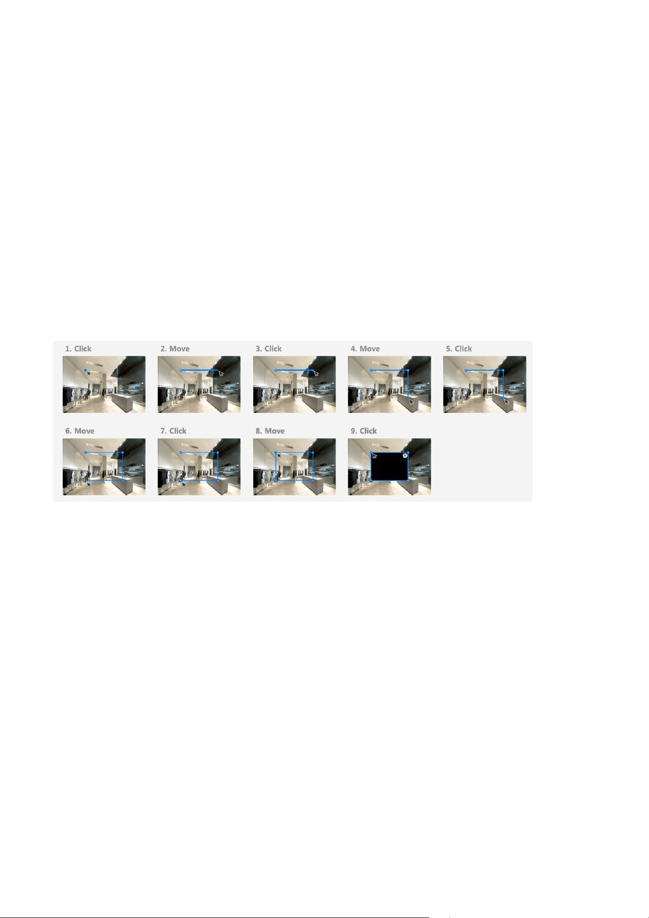
74
6 Detection
Enhancing Security with Real-Time Audio Anomaly
Detection for Prompt Response
Audio detection
Once you select “Profile mode”, additional settings become available:
• Enable profile mode: Toggle this on to activate condition-based settings.
• Night: Use different motion detection settings when the camera enters night mode.
• Schedule: Configure a time-based schedule (via the system’s scheduling page) to apply different
sensitivity and mask settings.
3. Adjust Sensitivity
Use the slider to set the camera’s motion detection sensitivity (e.g., 80%).
• Higher sensitivity detects smaller movements but may increase false alerts.
• Lower sensitivity avoids false positives but may miss subtle activity.
4. Set Motion Masks (Detection Zones)
Click Add to define up to 5 motion zones.
Each zone can:
• Be individually named (e.g., Motion1, EntranceZone).
• Be drawn manually to focus on specific areas and ignore others (e.g., fans, window reflections).
Audio detection enhances security by continuously monitoring ambient sound levels, such as loud noises,
glass breaking, or shouting. By analyzing real-time sound data and triggering alerts when the sound
exceeds a predefined threshold, it enables swift responses to potential security breaches or emergencies.
This proactive approach ensures that critical events are detected even in situations where visual cues are
insufficient, providing an additional layer of protection and improving overall situational awareness.
In Profile mode, each profile can have its own custom sensitivity and mask setup for maximum flexibility.
5. Save Your Settings
After setting up, be sure to save all changes to apply the motion detection configuration.
The audio detection feature in VIVOTEK cameras is a powerful tool for augmenting security and safety.
By detecting sound anomalies in real-time, it enhances the camera’s ability to monitor and respond to
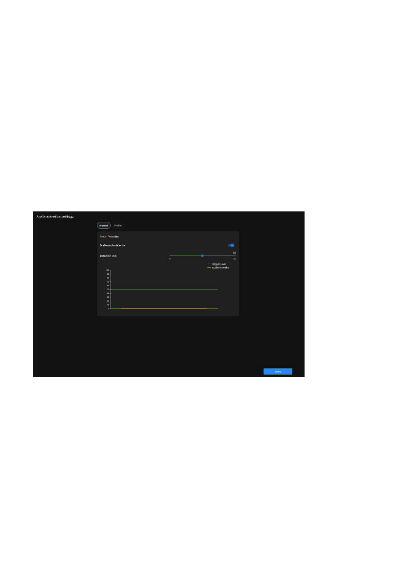
75
6 Detection
• Enhancing Security
Detects abnormal sounds (e.g., glass breaking, shouting, or explosions), enabling early identification of
potential threats.
• Supplementing Video Monitoring
Adds an extra layer of detection in situations where motion or visual triggers may not be effective (e.g.,
a quiet area with no visible motion).
• Real-Time Alerts
Notifies security personnel immediately when unusual sounds are detected, allowing for faster
responses.
• Environmental Noise Monitoring
Useful for monitoring sound levels in specific areas, such as factories, schools, or public spaces, to
ensure safety and compliance.
• Event Recording
Helps ensure that audio-related incidents are documented for review and investigation.
incidents effectively. Its primary purposes include:
Steps to configure the audio detection
Step 1. Access the Audio detection settings.
Click “Detection” category > “Audio detection” item on the Camera web UI.
Step 2. Enable Audio Detection.
Turn on the Enable Audio Detection toggle.
Step 3. Set the Detection Level.
Adjust the Detection Level slider.
• Higher levels filter out normal background noise, detecting only loud or unusual sounds.
• Lower levels detect even minor audio changes, useful for quieter environments.
Use the real-time graph to observe:
• Green Line (Trigger Level): Represents the detection threshold.
• Orange Line (Audio Intensity): Represents the live audio levels.
Adjust the slider to set an appropriate threshold based on your environment.
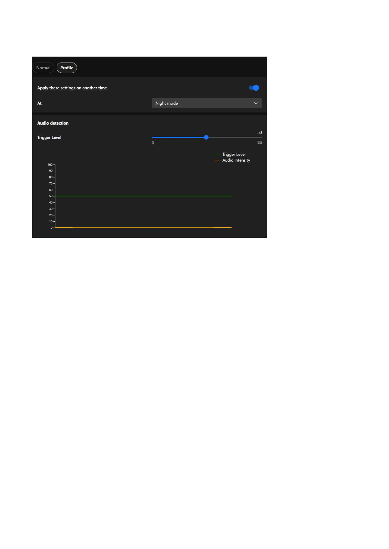
76
6 Detection
Protecting the Surveillance System from Visual
Obstruction
To ensure optimal performance and clear monitoring, protecting your surveillance system from visual
obstruction is crucial. Regularly inspect and maintain cameras to prevent blockages caused by dirt, debris,
or weather conditions. Strategically position cameras to avoid obstructions from vegetation, building
structures, or temporary barriers. Advanced features such as obstruction detection alerts can further
enhance reliability, ensuring uninterrupted surveillance coverage for critical areas.
The Profile Settings for Audio Detection allow users to configure detection settings tailored to specific
operational modes, such as Night Mode and Schedule Mode. These settings provide flexibility and
precision for various monitoring needs.
• Night Mode
Designed for quieter nighttime environments with lower ambient noise levels, it ensures heightened
sensitivity to detect unusual sounds, such as breaking glass or loud footsteps, that might indicate
security breaches. Lower thresholds for audio level detection can be applied to ensure even minor
disturbances trigger an alert, and the system can be activated automatically during preset nighttime
hours.
• Schedule Mode
It allows users to apply specific settings during predefined time periods, such as working hours,
weekends, or off-peak times, ensuring customized detection settings based on predictable noise
patterns. It enables precise scheduling for when audio detection thresholds or profiles should be active,
tailoring the sensitivity to the expected noise environment during the scheduled time.
Integrate audio detection-related settings into a profile
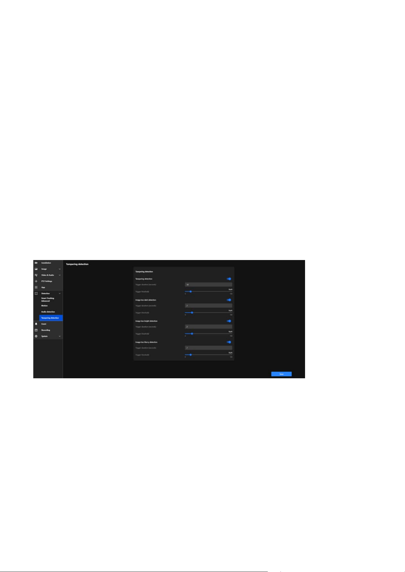
77
6 Detection
Tampering detection
Tamper detection is an advanced camera feature designed to identify incidents such as blocking,
defocusing, or spray paint interference. This functionality enhances the integrity and reliability of
surveillance systems by ensuring clear and accurate monitoring while providing timely alerts. Its primary
purposes include:
• Preventing Sabotage
Detects and alerts users about attempts to disrupt the camera’s operation, such as covering,
defocusing, or physically tampering with the device.
• Maintaining Image Quality
Monitors brightness and focus to ensure consistent video quality, providing actionable alerts if
anomalies are detected.
• Enhancing Security
Adds an additional layer of protection by identifying visual impairments or malicious actions that
compromise the surveillance system.
• Timely Response
Delivers real-time alerts to enable security personnel to respond immediately to tampering incidents or
visual issues.
• Operational Reliability
Ensures continuous, high-quality monitoring, even in challenging or high-risk environments.
Below are the detailed functionalities and corresponding settings for each feature:
Tampering detection
Detects physical tampering, including actions like blocking, covering, or moving the camera, ensuring
immediate alerts to maintain surveillance integrity.
• Trigger Duration (seconds):
Defines the amount of time tampering must persist before triggering an alert.
• Trigger Threshold:
Adjusts the sensitivity to tampering attempts. Lower thresholds are more sensitive but may result in
false alarms, while higher thresholds are less sensitive.
Image too dark detection
Detects when the video stream becomes abnormally dark due to intentional actions (e.g., turning off
lights) or environmental changes, ensuring timely alerts to address potential issues.

78
6 Detection
• Trigger Duration (seconds):
Sets the duration the image must remain dark to trigger an alert.
• Trigger Threshold:
Adjusts the sensitivity to darkness. Lower thresholds detect smaller changes, while higher thresholds
focus on significant darkness levels.
Image too bright detection
Detects when the video stream becomes overexposed, potentially caused by intense light directed at the
camera (e.g., flashlights) to obscure visibility, ensuring immediate alerts to maintain surveillance integrity.
• Trigger Duration (seconds):
Specifies how long the brightness issue must persist before triggering an alert.
• Trigger Threshold:
Adjusts sensitivity to brightness changes. Lower thresholds detect minor overexposure, while higher
thresholds only trigger for severe brightness levels.
Image too burry detection
Identifies when the video feed becomes blurry due to defocusing, lens obstruction, or environmental
factors such as condensation or dirt, ensuring timely alerts to maintain clear surveillance.
• Trigger Duration (seconds):
Defines how long the blurriness must persist to trigger an alert.
• Trigger Threshold:
Adjusts sensitivity to blurriness. Lower thresholds detect minor blurring, while higher thresholds focus
on significant quality degradation.
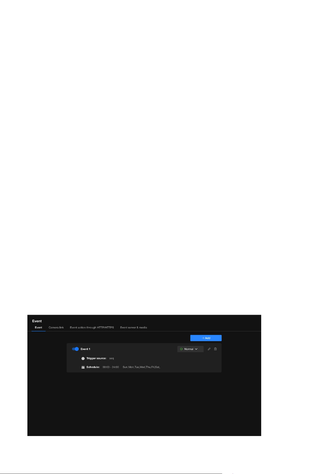
79
Event
7
Enhancing Security with Automated and Customizable
Event
Event
Event is a powerful tool designed to enhance security through automation and intelligent monitoring. It
allows users to define specific conditions, known as trigger sources, that activate pre-configured actions
such as recording, sending alerts, or controlling external devices. By customizing these events with
detailed schedules and conditions, users can ensure the system responds proactively to potential threats
or anomalies. This feature not only streamlines surveillance operations but also reduces the need for
constant manual monitoring, providing a reliable and efficient way to protect property and assets.
To enhance security with automated and customizable events, users can configure specific conditions to
activate surveillance actions. For example, motion detection, sound detection, or tampering can be set
as trigger sources. Once triggered, the camera can automatically record footage, send alerts via email, or
activate connected devices like alarms. Users can further customize these events by setting schedules,
such as enabling detection only during nighttime, or by linking multiple triggers for advanced scenarios.
This flexibility ensures a proactive and efficient security solution tailored to the user's unique needs.
Event is a smart automation tool designed to enhance the efficiency and effectiveness of security
monitoring. Its primary purpose is to detect specific conditions or triggers and automatically execute
predefined actions to respond to those events. This reduces the need for constant manual monitoring
and ensures timely reactions to critical incidents.
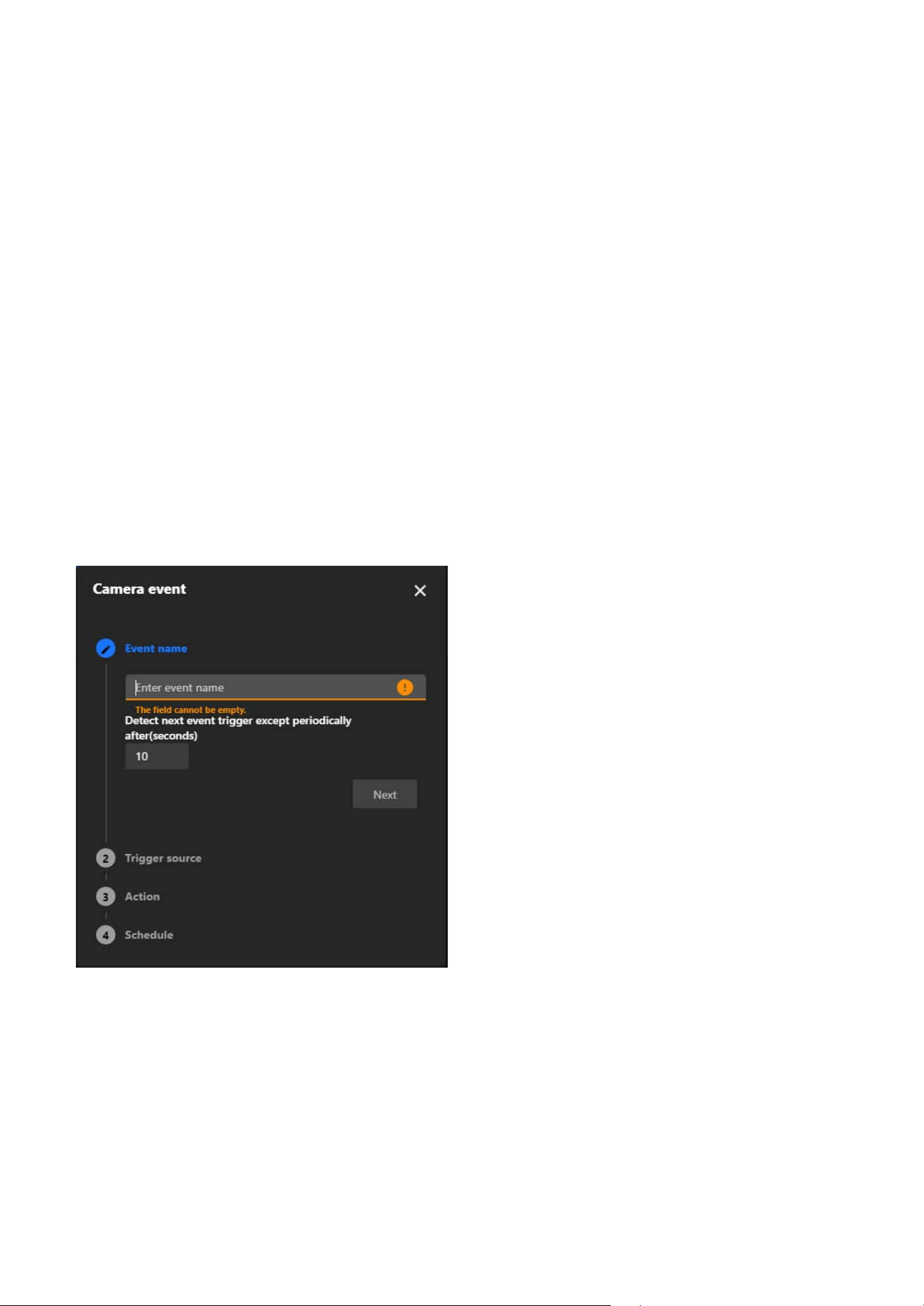
80
7 Event
Key purpose of Event:
• Enhance Security
By enabling cameras to respond instantly to suspicious activities, such as intrusions or tampering, users
can prevent incidents before they escalate.
• Increase Efficiency
Automating responses eliminates the need for constant manual monitoring, saving time and resources.
• Provide Evidence
Automatic recording and snapshot capture ensure crucial moments are documented for investigations.
• Proactive Problem Solving
Alerts for device or network issues allow users to address problems quickly, reducing downtime or
vulnerabilities.
Steps to Add an Event
Step 1. Enter Event Name
• Click “+ Add” button on “Event” configuration tab.
• In the Event Name field, enter a descriptive name for the event.
• Set the trigger interval. This determines how long the system waits before detecting the same
event again.
• Click Next to proceed.
Step 2. Select the Trigger Source
• Choose a trigger source from the list:
• Device
These triggers are based on the camera itself or external devices connected to it.
• Detection
These triggers rely on the camera's built-in intelligent analysis features to detect changes or
abnormalities in the environment.
• Recording
These triggers are based on the recording status of the camera.
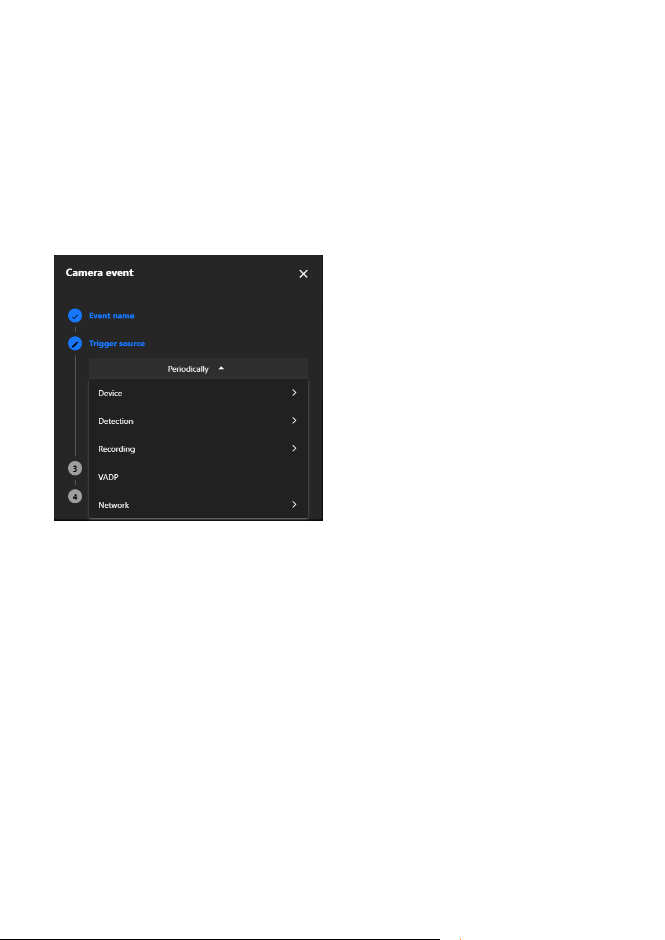
81
7 Event
• PTZ
This trigger is based on PTZ operations, such as moving to a preset point. It activates when the
camera reaches the specified position.
• VADP
VADP (VIVOTEK Application Development Platform) provides advanced trigger options
supported by custom applications.
• Network
These triggers are based on the network status or conditions.
• Configure any additional settings for the selected trigger source.
• Click Next to continue.
Step 3. Define Actions
• Select the actions to be performed when the event is triggered:
• Digital Output
Activates an external device, such as an alarm.
• Backup
Backups video footage to storage if the network is disconnected.
• Audio Clips
Plays a pre-configured audio clip (requires prior audio setup).
• Camera Link
Links to other cameras for coordinated responses.
• Event Server & Media
Defines the storage location, such as:
0. SD card
1. NAS
• Move to Preset Location
Moves the camera to a predefined preset position when the event is triggered. Optionally,
capture media after reaching the location to take snapshots.
• Event action through HTTP/HTTPS
Sends an HTTP/HTTPS request to an external system when the event is triggered.
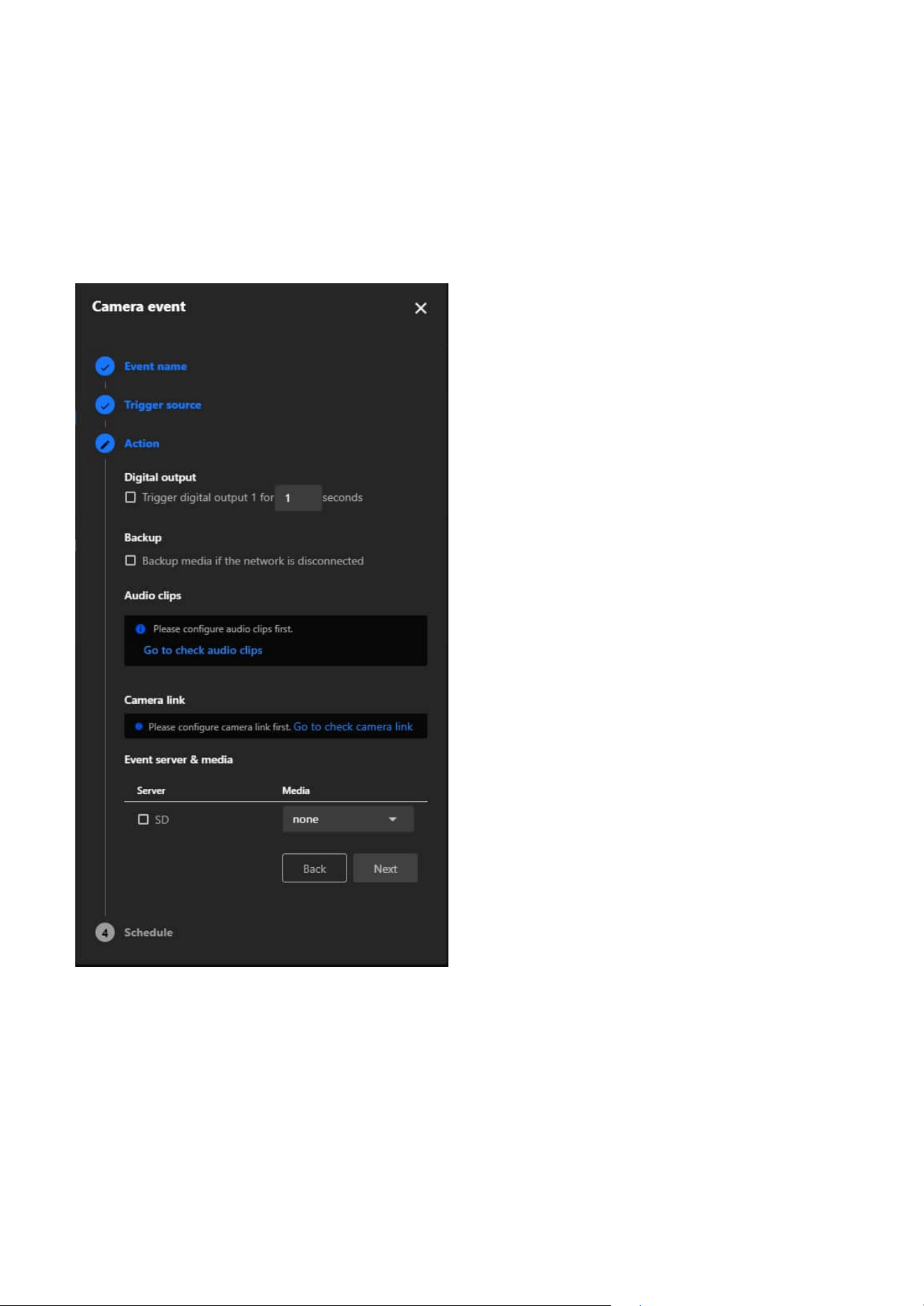
82
7 Event
Step 4. Set the Schedule
• Define when the event should be active:
• Always: The event will always be active.
• Custom: Configure the event to only be active during certain times (e.g., only at night).
• Review the schedule and confirm it.
• Click Save to finalize the setup.
• Trigger Patrol
Starts a predefined patrol route when the event is triggered.
• Trigger Track
Initiates auto tracking when the event is triggered. Users can configure the system to track
continuously (Trigger track) or to trigger tracking only once per event (Trigger track once).
• Customize the action settings as needed.
• Click Next to proceed.
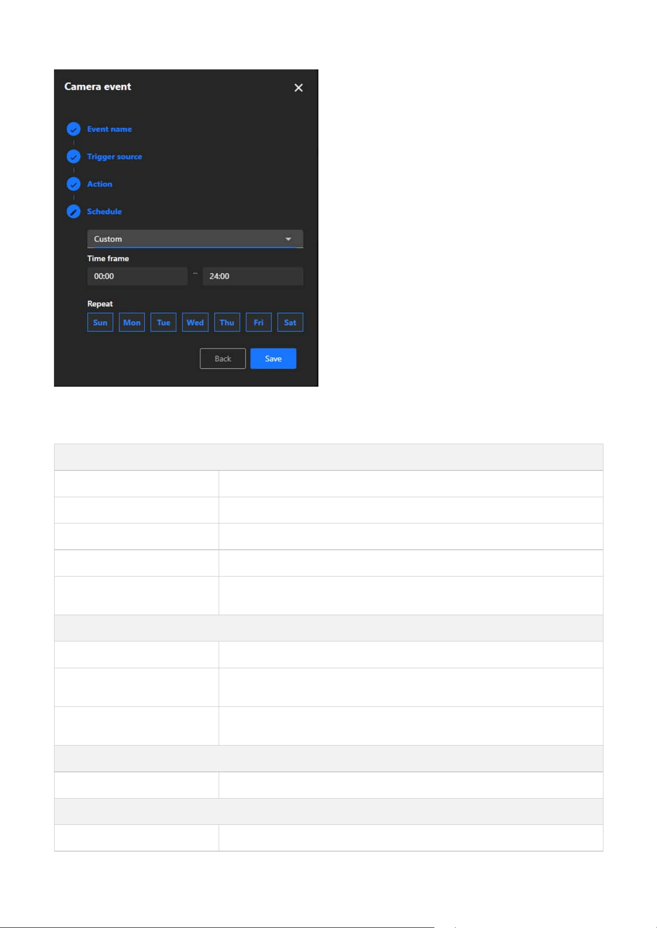
83
7 Event
Note
The types of Event triggers:
Device
Periodically The event is triggered at regular intervals, as defined by the user.
System Boot The event is triggered when the camera starts up.
Manual Trigger The event is manually triggered by the user.
Digital Input The event is triggered by a digital signal from an external device, such as a sensor.
Smart SD
The event is triggered when the system detects an abnormal condition on the SD
card, such as removal, error, or recording failure.
Detection
Motion Detection The event is triggered when the camera detects a moving object in its field of view.
Tampering Detection
The event is triggered when the camera detects tampering, such as being covered,
moved, or obstructed.
Audio Detection
The event is triggered when the camera detects abnormal sounds, such as sudden
loud noises.
Recording
Recording Notification The event is triggered when recording starts or stops.
PTZ
Preset Reached The event is triggered when the camera reaches a user-defined preset position.

84
7 Event
VADP
BruteForceAttack
The event is triggered when repeated failed login attempts are detected, indicating a
potential brute force attack on the camera system.
CyberAttack
The event is triggered when suspicious network activities resembling a cyberattack
targeting the camera are identified.
LicenseExpiration
The event is triggered when Trend Micro IoT Security license is approaching
expiration, alerting users in advance.
Quarantine
The event is triggered when unauthorized breaches or violations occur in a
designated quarantine zone.
Crossed
The event is triggered when an object or person crosses a predefined virtual
boundary.
ObjectIsCrowd
The event is triggered when crowd formation or high object density is recognized in a
specific area.
ObjectsInside The event is triggered when objects enter a user-defined monitored area.
ObjectIsLoitering
The event is triggered when objects or individuals linger in a designated area for an
extended period.
ObjectIsRunning
The event is triggered when fast-moving objects, such as running individuals, are
identified within the camera’s field of view.
ObjectsAbandoned The event is triggered when items are left unattended in a monitored zone.
ObjectsMissing
The event is triggered when objects are removed or disappear from a predefined
area.
Face
The event is triggered when human faces are recognized for identification or tracking
purposes.
Violated
The event is triggered when a restricted or prohibited action occurs in a defined
area.
ObjectIsRestricted
The event is triggered when objects enter or remain in restricted zones where they
are not permitted.
SmartTracking
The event is triggered when a detection rule (e.g., face, intrusion, or object detection)
is matched.
Network
Certificate Expiration Notify The event is triggered when the security certificate is about to expire.
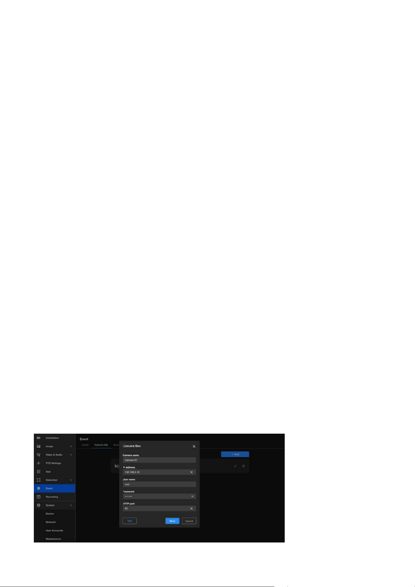
85
7 Event
Enhance Multi-Camera Coordination and Eliminate Blind
Spots with Camera Link
Camera link
The Camera link in Event settings enables seamless integration and coordination among multiple cameras,
ensuring comprehensive surveillance coverage and eliminating potential blind spots. By facilitating
interaction and collaborative responses to triggers, this feature enhances situational awareness, improves
monitoring efficiency, and provides a robust solution for complex security environments. Whether
managing large facilities, monitoring multiple zones, or ensuring full coverage in critical areas, Camera
Link empowers users with intelligent, event-driven operations tailored to their specific needs.
The Camera Link operates by enabling one camera to trigger actions on other linked cameras when an
event occurs. For example, the Camera Link feature enables a general form factor camera to pair with a
PTZ camera. When motion is detected in Motion Window #1, the paired PTZ camera will automatically
move to the designated preset position and initiate object tracking. This coordinated response ensures
comprehensive event coverage, effectively eliminating blind spots by capturing multiple perspectives in
real time, even in complex or large surveillance areas.
Key purpose of Camera link
• Multi-Camera Coordination
When an event is detected by one camera, it can trigger actions on other linked cameras, such as playing
an audio clip, moving to a preset location, or starting smart tracking for PTZ cameras. This makes it ideal
for small-scale monitoring scenarios where no VMS (Video Management System) is available for central
management.
• Centralized Management
The Camera Link feature consolidates multiple cameras into a unified system, streamlining operations
and boosting efficiency, making it particularly beneficial for monitoring systems in security control
centers, smart buildings, or commercial complexes.
• Enhanced Security
The Camera Link feature allows for multi-angle coverage of critical areas by enabling other cameras
to automatically capture footage from different viewpoints when an event is triggered in one zone,
effectively reducing blind spots and improving situational awareness.
• Data Integration and Event Logging
Events and recordings from multiple cameras can be centralized in one server or storage system,
enabling seamless event tracking and analysis.
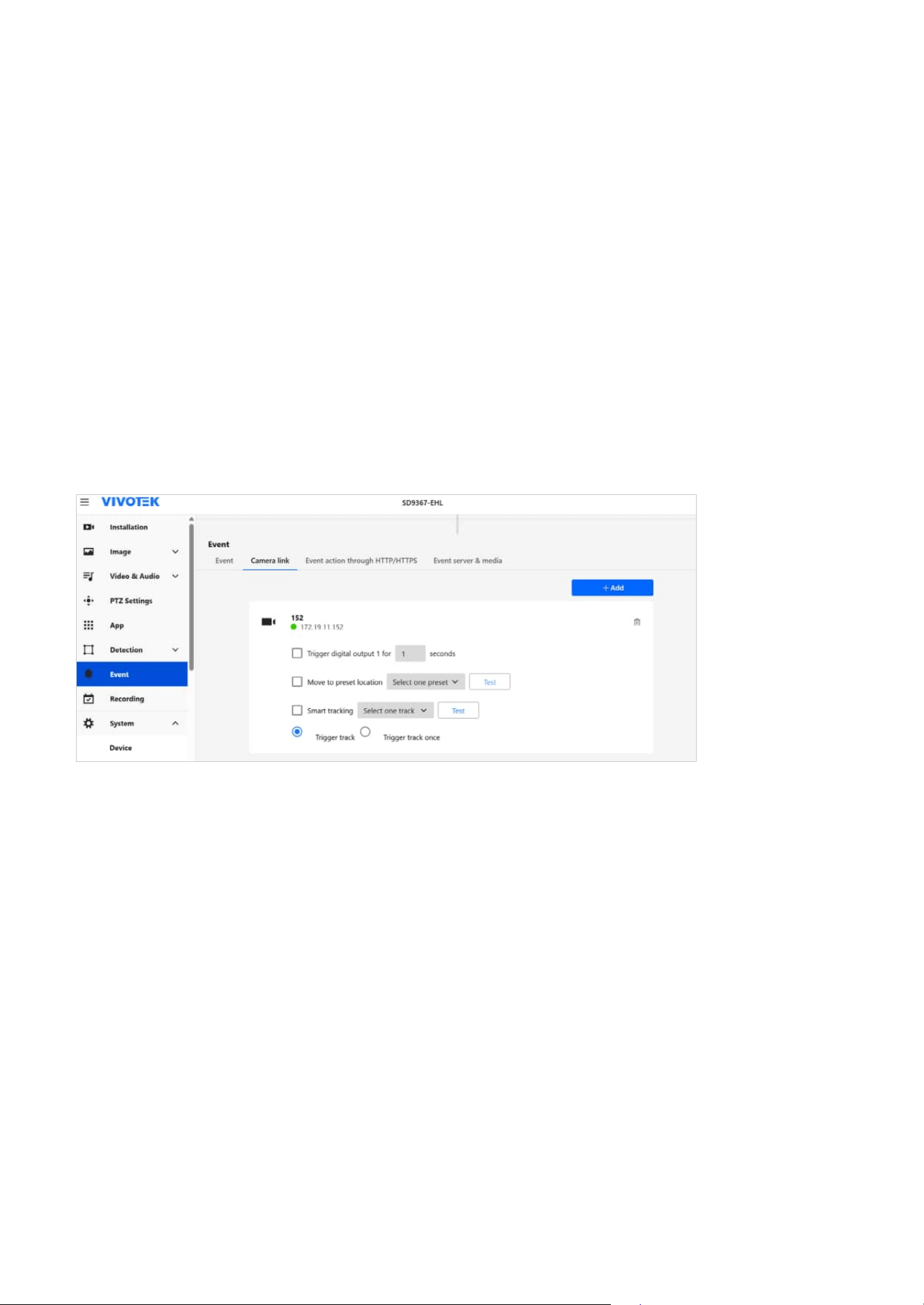
86
7 Event
Trigger Automated HTTP/HTTPS Requests for Event-Based
Integration
Steps to Add a Camera link
Step 1. Click on the + Add button to create a new camera link entry.
Step 2. Fill in Camera Details:
• Camera Name: Enter a descriptive name for the linked camera.
• IP Address: Provide the IP address of the target camera you want to link.
• Username: Enter the username required to authenticate with the target camera, usually "root"
by default.
• Password: Enter the corresponding password for the username.
• HTTP Port: Specify the HTTP port used by the target camera. By default, this is usually 80, unless
it has been customized.
Step 3. Click the Test button to ensure the connection details are correct and the camera link is
successfully established.
Step 4. Once the connection is successfully tested, click the Save button to store the camera link
configuration. If the linked camera is a PTZ camera, additional actions can be configured, such as
triggering digital output, moving to a preset position, and enabling Smart Tracking.
The VIVOTEK cameras can send HTTP/HTTPS requests to a specified server or API when a specific event
occurs. This enables integration with external systems for notifications, logging, or automation.
Steps to Add a new HTTP/HTTPS event action
Step 1. Click on the + Add button to create a new HTTP/HTTPS event action.
Step 2. Fill in details:
• Server Name: Identifies the event action.
• Server Address: The target server or API URL.
• Header Key & Value: Optional HTTP headers.
• Method:
• GET: Requests data from the target server, typically for information retrieval.
• POST: Sends data to the target server, typically for event reporting or triggering actions. When
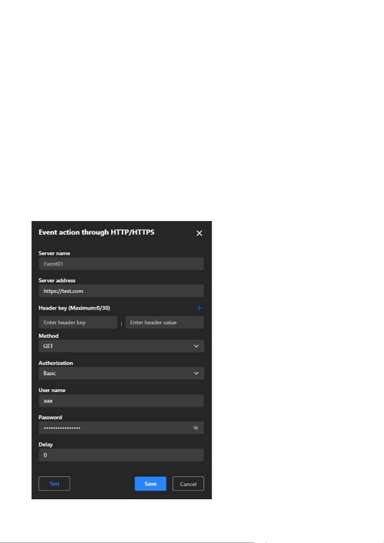
87
7 Event
POST is selected, the Post Body type must be specified:
• Static: Requires a manually entered Static Body, which remains the same for every event
trigger.
• ONVIF Event: Requires selecting an ONVIF Event Topic (e.g., tns1:RuleEngine/MotionDetector/
Motion). The event will be sent using the ONVIF standard format, suitable for ONVIF-
compliant systems.
• Authorization:
• Basic Authentication: Requires User Name and Password.
• Digest Authentication: A more secure authentication method than Basic Authentication, as
the password is not transmitted directly but hashed instead. Still requires User Name and
Password, with server-side challenge-response validation.
• Delay:
Specifies the delay (in seconds) before executing the request after an event is triggered.
Step 3. Click the Test button to ensure the connection details are correct and the HTTP/HTTPS event
action is successfully established.
Step 4. Once the connection is successfully tested, click the Save button to store the HTTP/HTTPS event
action configuration.
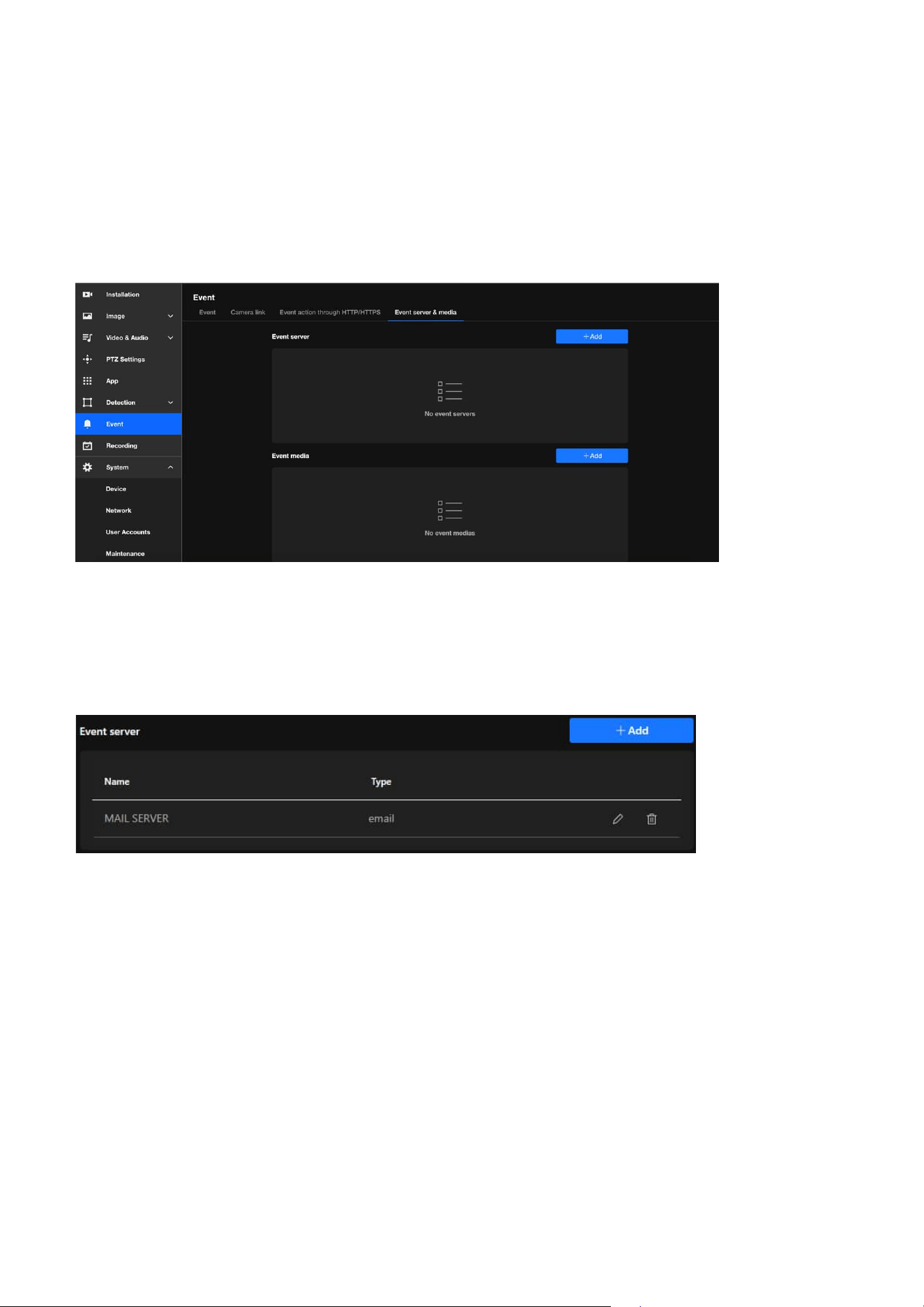
88
7 Event
Effortless Event Management and Enhanced Security with
Event Server & Media
Digital Output (DO)
By offering various types of event servers, VIVOTEK cameras provide a flexible and robust event
management solution that can be customized to meet diverse security and monitoring requirements. The
main functions and purposes of these servers are as follows:
The Event Server & Media offers robust functionality that simplifies event management, improves
security, and enhances user convenience. It ensures that event data is handled efficiently, reliably,
and in a manner tailored to each user’s unique requirements, making it an invaluable tool for modern
surveillance systems.
• E-mail
This solution sends email notifications to predefined recipients whenever an event occurs, instantly
alerting users with detailed event information. It also supports attaching snapshots or event-related
data, making it an ideal choice for small-scale setups or individual monitoring needs.
• FTP
This solution uploads event-related files, such as snapshots, videos, or logs, to an FTP server, providing
centralized storage for event media. It is ideal for managing event data in environments with consistent
network connectivity and is particularly suited for large-scale deployments that require organized and
efficient storage solutions.
• SFTP
This solution securely uploads event-related files to an SFTP server using encryption protocols,
enhancing data protection during transfer. It is ideal for environments requiring the safeguarding
of sensitive information from interception or tampering and ensures compliance with strict security
policies and regulatory requirements.
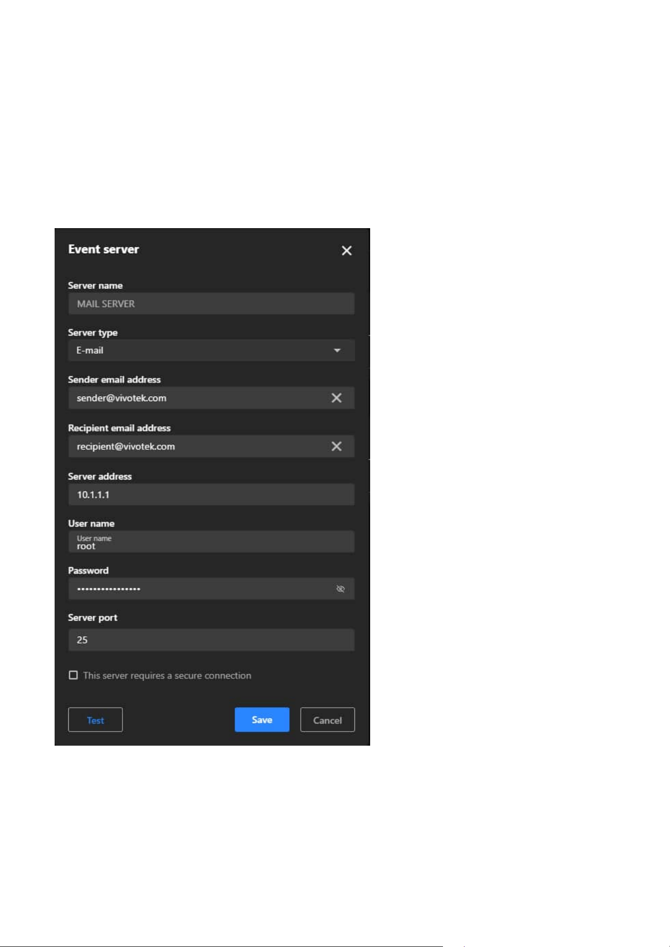
89
7 Event
• HTTP
This solution sends event notifications or data to an HTTP server via HTTP requests, enabling seamless
integration with third-party systems or applications for efficient event handling. It can trigger workflows
in advanced security systems, home automation setups, or analytics platforms, and simplifies
integration in environments that rely on custom APIs or HTTP-based solutions.
• HTTPS
This solution uses the secure HTTPS protocol for encrypted communication, ensuring secure data
transfer to prevent unauthorized access or data breaches. It is ideal for sensitive applications requiring
confidentiality and is commonly implemented in modern, secure network environments.
Steps to configure an Event server
Step 1. Click the + Add button to add a new server.
Step 2. In the popup window, choose the type of server you want to configure:
• Email: For sending event notifications via email.
• FTP: For uploading event-related files (e.g., snapshots or videos) to an FTP server.
• SFTP: Similar to FTP but uses encrypted file transfer for added security.
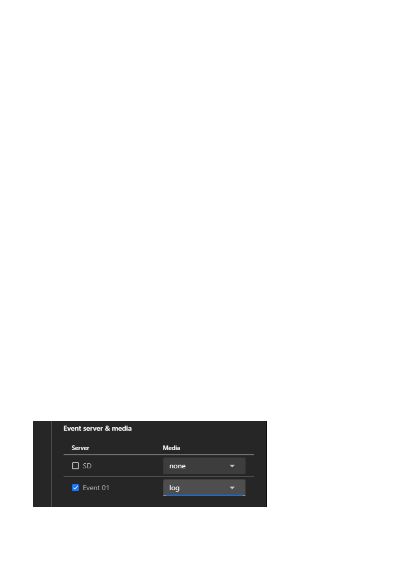
90
7 Event
• HTTP: For sending HTTP requests to a third-party system with event information.
• HTTPS: Similar to HTTP but uses a secure communication protocol.
Step 3. Click Next to proceed with the server-specific configuration.
Step 4. Depending on the server type selected, fill in the required fields:
• Email Server:
• SMTP Server: Enter the SMTP server address (e.g., smtp.example.com).
• Port: Specify the port (e.g., 25, 465, or 587 depending on the SMTP configuration).
• Authentication: Enable and enter the username and password for the email account.
• Sender Email Address: Enter the "From" address for email notifications.
• Recipient Email Address: Enter the recipient's email address for receiving notifications.
• FTP Server:
• FTP Server Address: Enter the IP address or domain name of the FTP server.
• Port: Default is 21 (adjust if needed).
• Username and Password: Enter credentials to authenticate with the FTP server.
• Folder Path: Specify the folder where files should be uploaded.
• SFTP Server:
Similar to FTP, but ensure the SFTP protocol is supported, and credentials are entered securely.
• HTTP Server:
• Server URL: Enter the full URL of the HTTP server (e.g., http://example.com/api/event).
• HTTPS Server:
Same as HTTP but ensure the server URL starts with "https://".
Note
Upload and configure certificates if required for secure communication.
Step 5. Click the Test button to verify that the camera can successfully connect to the server.
Step 6. After a successful test, click "Save" to store the server configuration, and the new server will
appear in the Event Server list.
Step 7. Link the Server to an Event
• Navigate back to the Event tab.
• Create a new event or edit an existing one.
• Select the configured server under the Camera Event >
③
Action > Event Server & Meida
section.
• Define the actions and media to be sent to the server when the event is triggered.
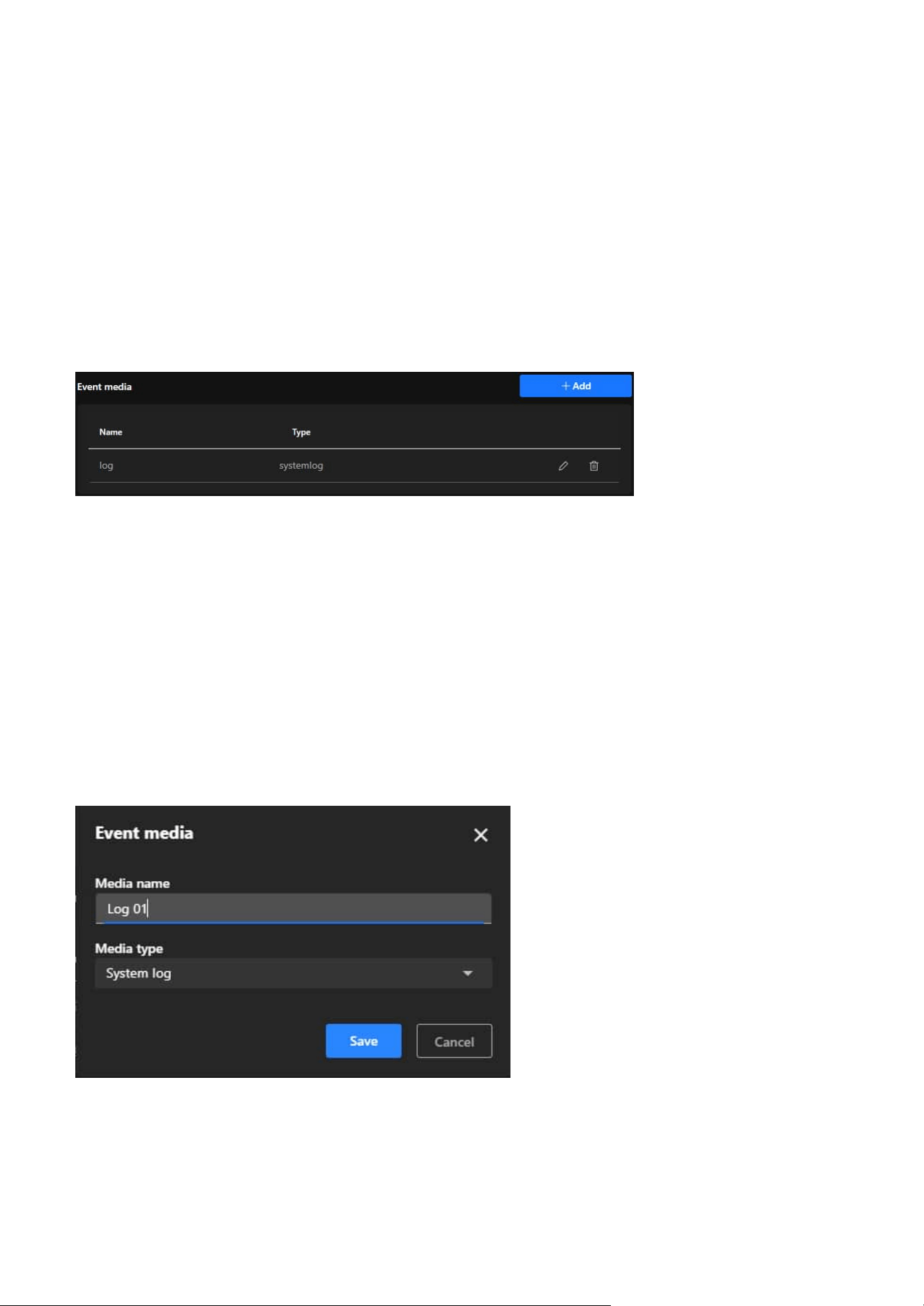
91
7 Event
Event media
• Snapshot
Captures a still image at the moment the event is triggered, providing a quick visual representation of
the event that is useful for reviewing specific moments or identifying key elements such as faces or
objects.
• Video clip
Records a short video segment before, during, and after the event is triggered, offering detailed context
and a dynamic view of the event to help users thoroughly analyze incidents such as the movement of
individuals or objects.
• System log
Records textual data about the event, including the type of event, time, and related system activity,
providing a chronological record for audits and troubleshooting while being useful for monitoring
system performance and identifying anomalies.
The Event Media settings offer a powerful and flexible media management solution, enabling users
to quickly generate, store, and transmit media files during events. This meets the needs for real-time
monitoring, event recording, and evidence preservation, further enhancing the efficiency and reliability of
surveillance systems. The main functions and purposes of these servers are as follows:
Notice
• Use strong and unique passwords for server authentication to enhance security.
• For HTTPS and SFTP, ensure certificates and encryption settings are correctly configured.
• Regularly monitor and test the server connection to ensure reliable event handling.
Steps to configure an Event server
Step 1. Click the + Add button to create a new media configuration.
Step 2. Enter a descriptive name for the media in the Media Name field
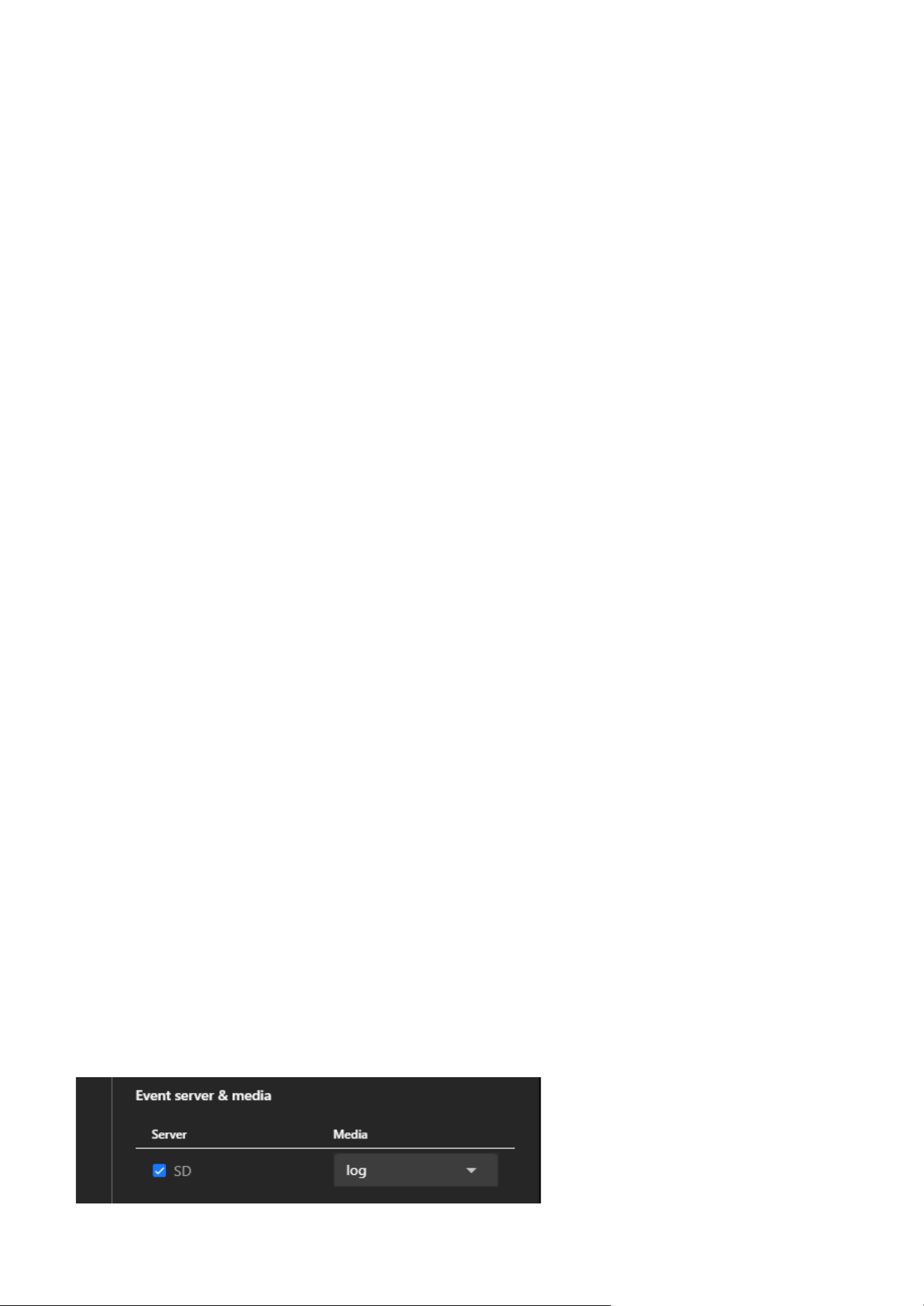
92
7 Event
Step 3.
Select Media Type
• Choose one of the following media types from the dropdown menu:
• Snapshot: Captures a still image.
• Video Clip: Records a short video clip.
• System Log: Logs textual data about the event.
Step 4. Configure Media-Specific Settings
• Snapshot:
• Source: Select the video stream from which snapshots will be taken.
• Pre-Event Buffer (seconds): Define how many seconds before the event to capture snapshots.
• Post-Event Buffer (seconds): Define how many seconds after the event to continue capturing
snapshots.
• Custom Image Frequency (frames/second): Set the frequency for capturing images (e.g., 1~5
frames per second).
• File Name Prefix: Enter a custom prefix for snapshot filenames.
• Optionally, enable the checkbox to add a date and time suffix to filenames for better
organization.
Caution
The resolution setting may affect the maximum number of snapshots that can be taken. Please
refer to the Video & Audio > Video > Steam page for more information.
• Video clip:
• Source: Select the video stream to record from.
• Pre-Event Recording (seconds): Define how many seconds before the event the recording
should start.
• Maximum Duration (seconds): Set the maximum length of the video clip (e.g., 5 seconds).
• Maximum File Size (KB): Specify the maximum file size for the video clip.
• File Name Prefix: Enter a custom prefix for video filenames for easy identification.
• System Log:
This media type will record event-related data such as event type, time, and associated system
activity.
Step 5. After configuring the settings, click "Save" to finalize the media configuration, which will then
appear in the Event Media list.
Step 6. Link Event Media to an Event.
• Navigate to the Event tab.
• Create a new event or edit an existing one.
• In the event settings, select the configured media under the Event Media section.
• This ensures the configured media (e.g., snapshots, video clips, or system logs) will be generated
when the event is triggered.
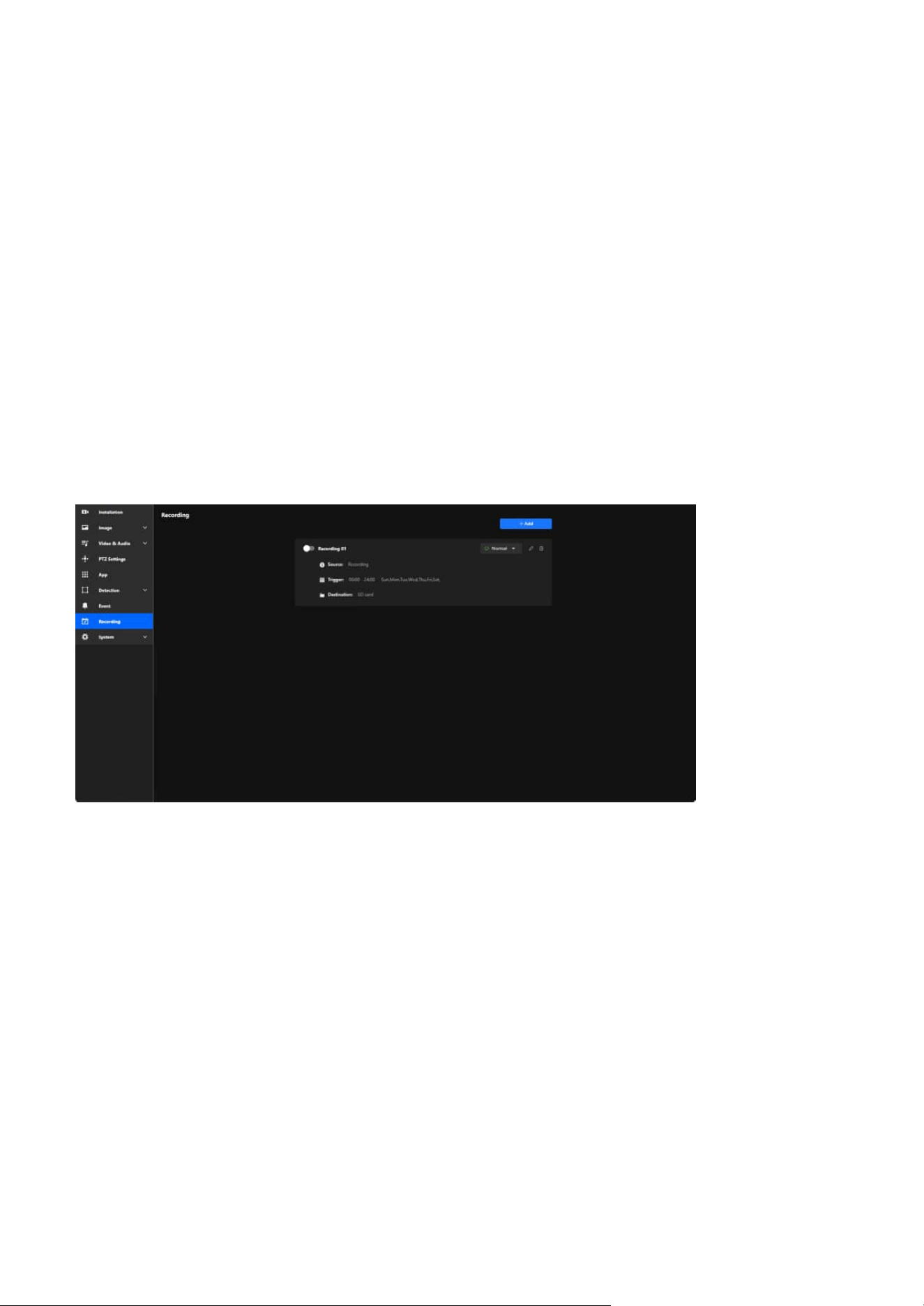
93
Recording
8
Maximize Surveillance and Storage with Tailored
Recording Settings
The Recording settings empower users to customize their surveillance experience with precision and
efficiency. By offering flexible scheduling, event-based triggers, and multiple storage options, these
settings ensure that critical footage is captured while optimizing storage usage. Whether you need 24/7
monitoring or recordings triggered by specific events like motion or sound, the system adapts seamlessly
to your needs. With the ability to store recordings locally on an SD card or on a network drive, users can
ensure data security and accessibility. This customizable approach simplifies management, enhances
security, and provides peace of mind, making it a vital feature for any surveillance setup.
Key purpose of Recording:
• Surveillance and Security
Ensures critical areas are monitored and video evidence is captured, whether continuously or based on
events.
• Event Investigation
Allows users to review recordings to investigate incidents or analyze activities.
• Efficient Storage Management
By setting specific schedules and triggers, unnecessary recordings are minimized, conserving storage
space.
• Flexibility for Different Scenarios
Accommodates various recording needs, such as round-the-clock monitoring or selective recording
based on motion detection or specific timeframes.
• Backup and Data Accessibility
Ensures recordings are stored securely and can be accessed as needed, either from local SD cards or
networked storage solutions.
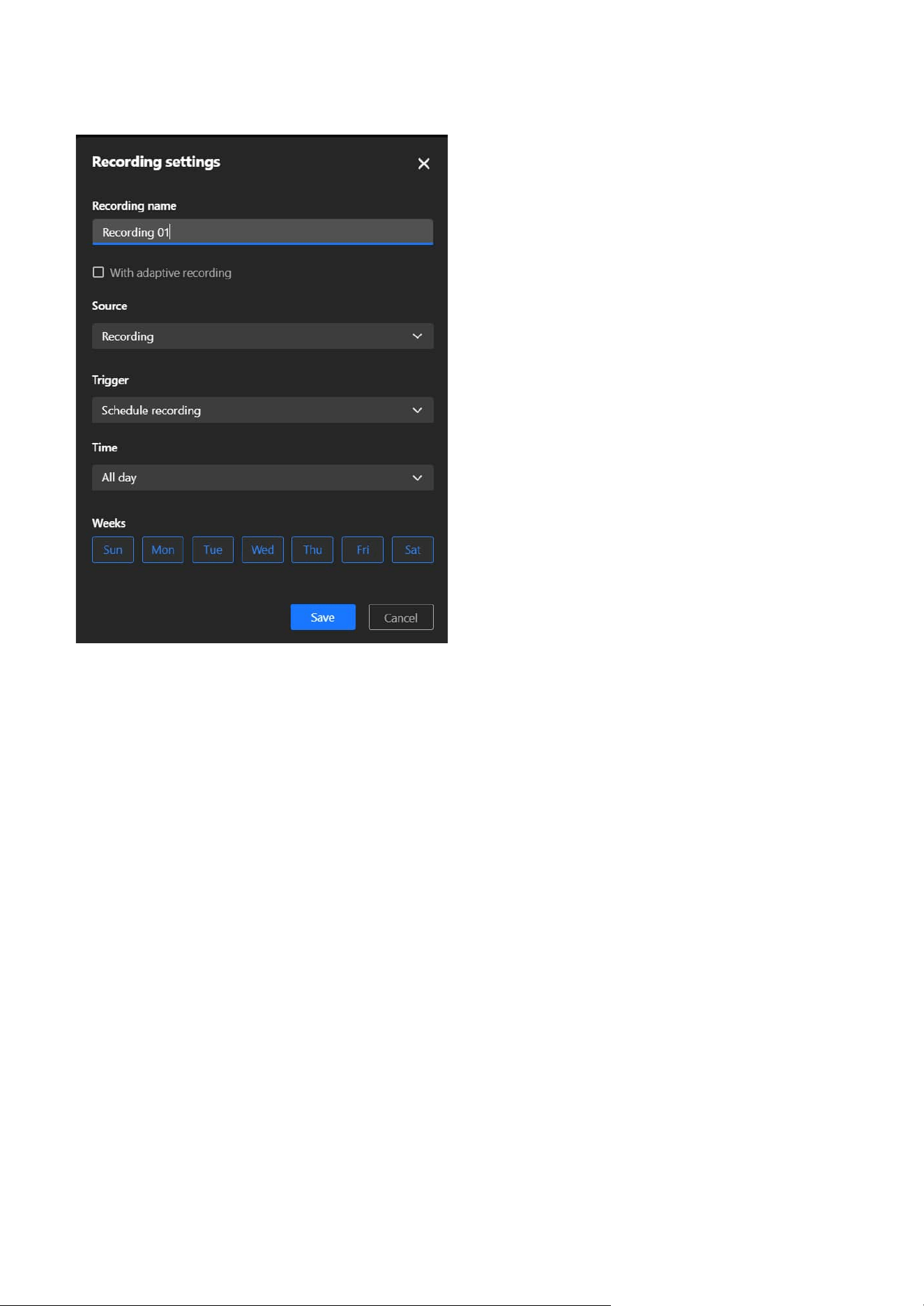
94
8 Recording
Steps to configure Recording
Step 1. Click the +Add button to open the Recording Settings panel.
Step 2. In the Recording name field, type a descriptive name for this recording schedule.
Step 3. Check the With adaptive recording box if needed.
Step 4. Under Source, choose the appropriate media profile from the dropdown menu. Media profiles
are predefined configurations in the Video & Audio settings of the camera.
Step 5. Under Trigger, select one of the following options:
• Schedule recording
Records based on a predefined time schedule. This is the most commonly used option for
continuous or time-based recording. After selecting Schedule recording, configure the time
interval:
• All Day: Records continuously, 24/7.
• Custom: Set specific time frames (e.g., weekdays from 9:00 AM to 6:00 PM).
• Network fail
Triggers recording only when the camera detects a network failure. This ensures footage is
recorded locally on the SD card when network connectivity is interrupted, providing a fail-safe
mechanism.
Step 6. Under Destination, select where the recordings will be stored:
• SD
Save recordings locally on the SD card inserted in the camera. This option is ideal for standalone
setups or when local storage is sufficient.

95
8 Recording
With adaptive recording
Adaptive Recording is an intelligent feature designed to optimize surveillance efficiency by dynamically
adjusting the video frame rate based on real-time events. By reducing bandwidth and storage usage
during routine monitoring and ensuring high-quality video during critical events, Adaptive Recording
enhances both system performance and resource management. Its primary purposes are:
• Bandwidth and Storage Optimization:
During normal monitoring, the system reduces bandwidth consumption and storage usage by only
sending I-frame data.
• Enhanced Event Recording:
When an alarm is triggered, the frame rate increases to the full frame rate to capture critical moments
in high quality.
• Resource Efficiency:
The system optimizes frame rate usage based on actual needs, ensuring efficient use of network and
storage resources without compromising performance.
How does Adaptive Recording achieve the above purposes?
1. Dynamic Frame Rate Adjustment:
• When Adaptive Recording is enabled, the camera dynamically adjusts the frame rate based on alarm
triggers, such as motion detection, DI devices, or manual triggers.
• When an alarm is triggered:
• The camera records the full frame rate streaming data to ensure high-quality video for critical
events.
• When no alarm is triggered:
• The camera only sends Intra frame (I-frame) data during normal monitoring to minimize bandwidth
and storage usage.
2. Frame Rate Control:
• No Alarm Trigger:
• JPEG mode: 1 Intra frame (I-frame) per second.
• H.264 mode: Records Intra frame (I-frame) only.
• Alarm Trigger:
Automatically increases to the configured full frame rate.
3. Frame Period Limitation:
If the Intra frame (I-frame) period is greater than 1 second in the Video & Audio > Video > Stream page,
the firmware will automatically reduce it to 1 second when Adaptive Recording is enabled.
Note
If an SD card is not detected or improperly installed, a warning message will appear. Ensure an SD
card is inserted or configure the NAS settings before proceeding.
Step 7. Once all fields are configured, click Save to apply the settings.

96
System
9
Centralized Management for System Monitoring and
Camera Configuration
The Device item serves as a centralized interface for monitoring and configuring the essential system
information, operational status, and hardware settings of the camera. Its primary purpose is to provide
users with real-time insights into system performance (CPU, memory, and storage), enable easy
identification and management of the device through network and hardware details, ensure accurate
time synchronization for recordings and logs, and facilitate integration with external devices through
LED and DIDO controls. Overall, it enhances the camera's manageability, performance monitoring, and
operational precision in a user-friendly manner.
The Device item features four functional cards covering the camera's operational status, basic device
information, system time synchronization, and interaction with external devices. Its main purposes are as
follows:
• Real-time Monitoring
Helps users track resource usage and storage capacity of the camera.
• Identification and Management
Facilitates easy identification and network management through basic device information.
• Time Synchronization
Ensures the accuracy of recording files and event logs.
• External Device Integration
Enables interaction with external devices to expand functional applications.
These functions are designed to enhance the camera's usability, operational flexibility, and integration
capability with other devices.
The System acts as a comprehensive management hub designed for configuring and monitoring the
device. It offers essential tools to manage the camera's system information, network configurations, user
accounts, storage solutions, and maintenance tasks. Its core aim is to ensure secure and efficient device
operation by enabling features like firmware updates, log analysis, and system diagnostics. Additionally, it
improves user experience through customizable themes and streamlines data management by organizing
storage and file handling. This category plays a vital role in maintaining optimal camera performance and
ensuring its seamless integration into a networked environment.
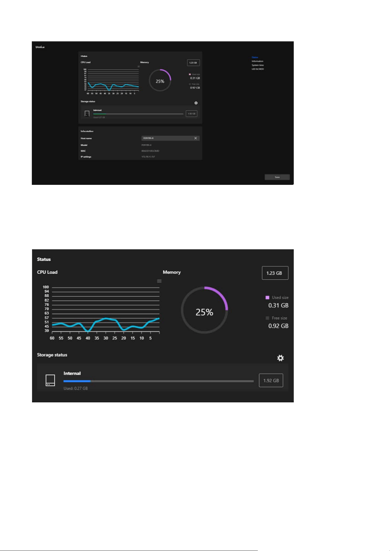
97
9 System
Status
The Status card serves as a real-time dashboard for monitoring the camera's operational performance. By
providing detailed insights into CPU, memory, and storage usage, it helps users maintain optimal device
performance, ensure system stability, and proactively address resource management needs.
CPU Load
• Displays the real-time CPU usage of the camera as a line graph, showing fluctuations over time.
• Helps users monitor processor load trends and identify potential performance issues.
Memory
• A circular graph visualizes the memory usage, including total memory capacity, used memory, and
available memory.
• Detailed figures for used and free memory are shown for precise monitoring.
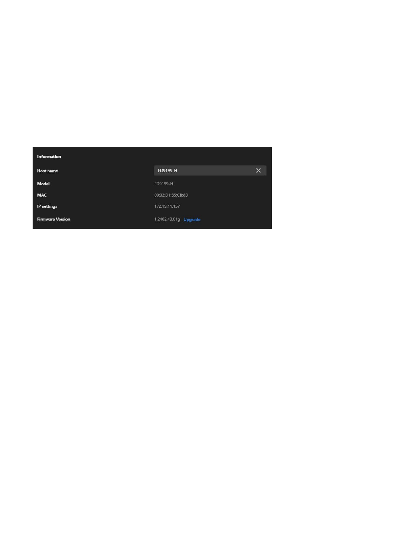
98
9 System
Information
System Time
Host Name
• Displays the camera's unique name.
• Can be edited by the user to customize and identify the camera more easily within a network.
Model
• Shows the camera's model number.
• Helps in identifying the specific device for maintenance or troubleshooting.
MAC Address
• Displays the camera’s unique MAC address.
• Useful for network diagnostics, device identification, or IP reservation purposes.
IP Settings
• Shows the camera’s current IP address.
• Allows users to confirm the network connectivity and configuration.
Firmware Version
• Displays the current firmware version installed on the camera.
• Includes an Upgrade option for users to update the firmware, ensuring access to the latest features, bug
fixes, and security improvements.
The Information card provides essential details for identifying, configuring, and maintaining the camera.
It simplifies network management, ensures the camera is up to date, and provides quick access to critical
device information, aiding in efficient management and troubleshooting.
The System Time card is essential for ensuring that the camera's time is accurate and synchronized with
its operating environment. By offering flexible configuration options, it supports reliable event tracking,
seamless system integration, and precise log management, enabling efficient and consistent monitoring
in various setups.
Storage Status
• Displays the status of internal storage, including total storage capacity, used storage space, and
available storage, represented by a progress bar for clear visualization.
• Includes options for further storage management via the gear icon.
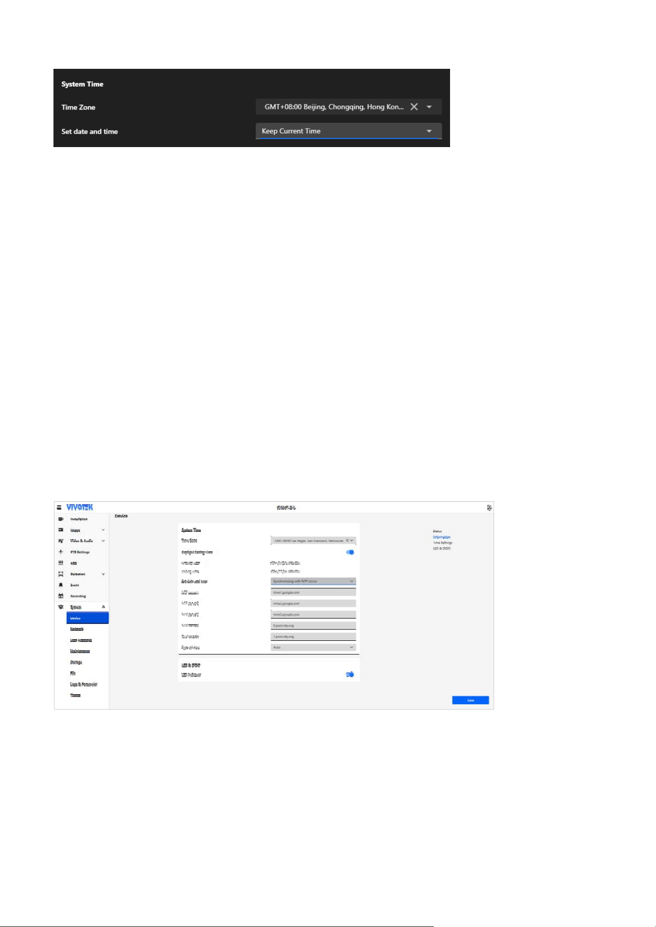
99
9 System
LED & DIDO
The LED & DIDO card provides control settings for both the camera’s LED indicator and its digital input/
output (DI/DO) interfaces. The LED setting offers a simple toggle to enable or disable the camera's status
LED, allowing users to adjust its visibility based on the installation environment and surveillance needs.
The DIDO setting (available only on models that support DI/DO) enables integration with external devices
through digital input and output interfaces. This allows for enhanced functionality such as alarm triggers,
automated responses, and advanced monitoring applications.
Time Zone
• Allows users to select the time zone based on the camera’s location (e.g., GMT+08:00 Beijing, Chongqing,
Hong Kong).
• Ensures the camera’s time aligns with the local time for accurate recording and event logging.
Set date and time
Offers four options for configuring the camera’s time:
• Keep Current Time
Retains the existing time configuration on the camera without changes.
• Synchronize with PC
Matches the camera’s time to the time on the connected computer, providing a quick and convenient
way to set the time.
• Manual
Enables users to manually set the date and time, suitable for specific use cases requiring custom time
settings.
• Synchronizing with NTP Server
Synchronizes the camera’s time with a Network Time Protocol (NTP) server to maintain accurate,
automated time updates. The system supports up to five NTP servers, checked sequentially from 1 to
5. Synchronization begins with the first server and automatically proceeds to the next if the connection
fails. The synchronization interval can be configured as required.
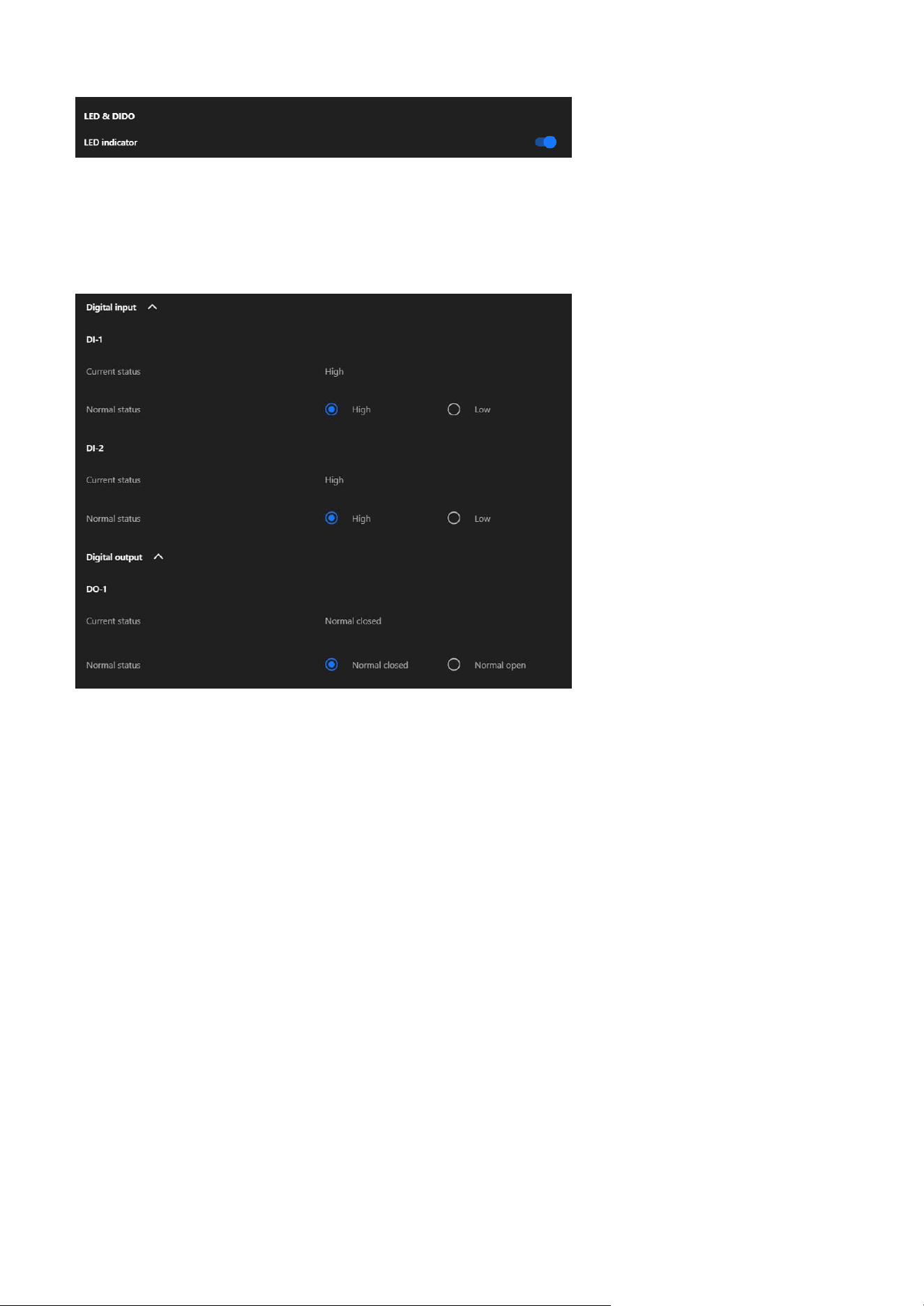
100
9 System
LED Indicator
• A toggle switch to enable or disable the camera’s LED indicator.
• When enabled, the LED provides visual feedback for the camera’s operational status (e.g., power on,
recording, or activity detection).
Digital Input
• DI-1/DI-2 Current Status
Displays the real-time status of the digital input (e.g., High or Low).
• DI-1/DI-2 Normal Status
Allows the user to configure the expected normal state for the digital input (either High or Low). Used
for integrating external sensors (e.g., motion detectors or alarms).
Digital Output
• DO-1 Current Status
Shows the current state of the digital output.
• DO-1 Normal status
Allows users to define the default state for the digital output (Normal Closed or Normal Open). This
setting determines how the output behaves when inactive and is typically used for controlling external
devices such as alarms, lights, or actuators.
Note
• High/Low in DI reflects the input signal received from external devices, used for monitoring the status
of sensors or triggers.
• Normal Closed/Normal Open in DO controls the output signal sent to external devices, used to activate
or deactivate connected equipment such as alarms or actuators.
• For detailed installation and configuration instructions, please refer to Appendix A: DI/DO
Configuration Guide.
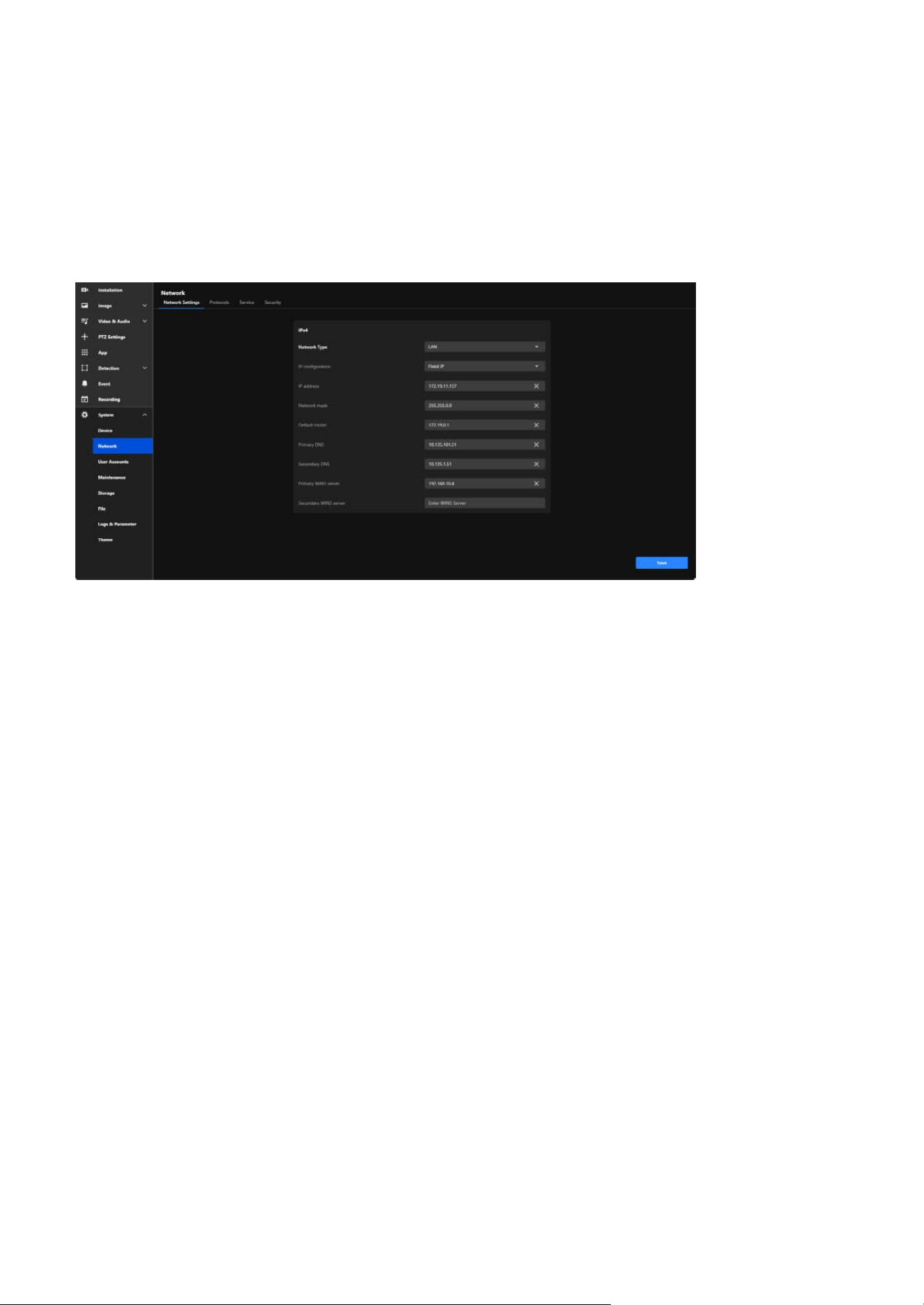
101
9 System
Configure and Secure Your Camera's Network Connection
for Seamless Communication
Network Settings
By providing detailed configuration options for both IPv4 and IPv6, the Network Settings tab ensures the
camera can seamlessly connect to and operate within diverse and complex network environments.
The main functional purposes are as follows:
Network Integration
Allows the camera to connect to local networks or the internet through proper IP settings, enabling
remote access and monitoring.
Customized Configuration
Provides flexible network parameter settings (e.g., static or dynamic IP) to ensure compatibility with
various network environments.
Reliable Communication
Ensures seamless communication with external systems (e.g., NVRs or cloud platforms) through proper
configuration of gateways, DNS, and protocols.
Security
Supports secure connections and access controls to protect the camera and its data from unauthorized
access or threats.
Efficient Monitoring and Maintenance
Facilitates network troubleshooting and diagnostics using tools like WINS and DNS settings to ensure
continuous operation.
The Network section provides comprehensive tools for configuring the camera’s network connectivity,
ensuring reliable communication, remote access, and secure integration with other devices and
systems. This configuration is critical for enabling real-time monitoring, remote management, and data
transmission over various network infrastructures.
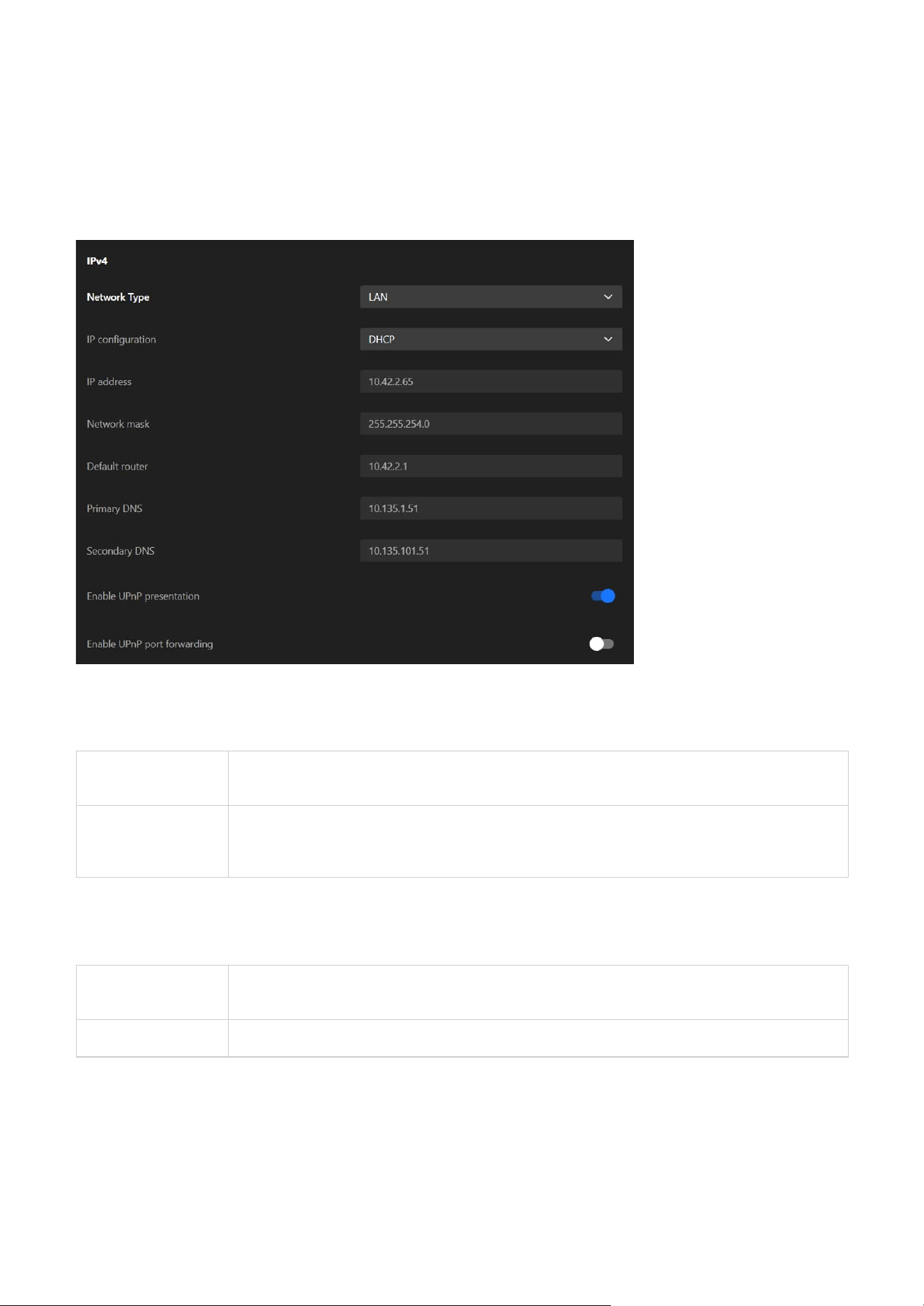
102
9 System
LAN
A standard wired network connection, typically used when the camera is connected to a local
network through Ethernet.
PPPoE (Point-to-
Point Protocol
over Ethernet)
A protocol used for direct internet connections, often requiring authentication with a username
and password from the Internet Service Provider (ISP). It’s commonly used in DSL networks or
when the camera needs to connect directly to the internet without a router.
DHCP
Dynamically assigns an IP address to the camera using a network DHCP server, suitable for
networks with automated address assignment.
Fixed IP Assigns a static IP address to the camera for consistent and reliable identification on the network.
IPv4
Network Type
Allows the user to select the type of network connection:
IP Configuration
Provides two configuration options:
The IPv4 card plays a vital role in setting up the camera’s network configuration and ensuring effective
communication. It facilitates dependable connectivity, enables both local and remote access, and allows
the camera to integrate effortlessly into IPv4-based networks. This configuration is crucial for maintaining
stable and efficient performance across diverse networking environments.
IP Address
Displays or sets the IPv4 address of the camera, which serves as the unique identifier for the camera
within the network.
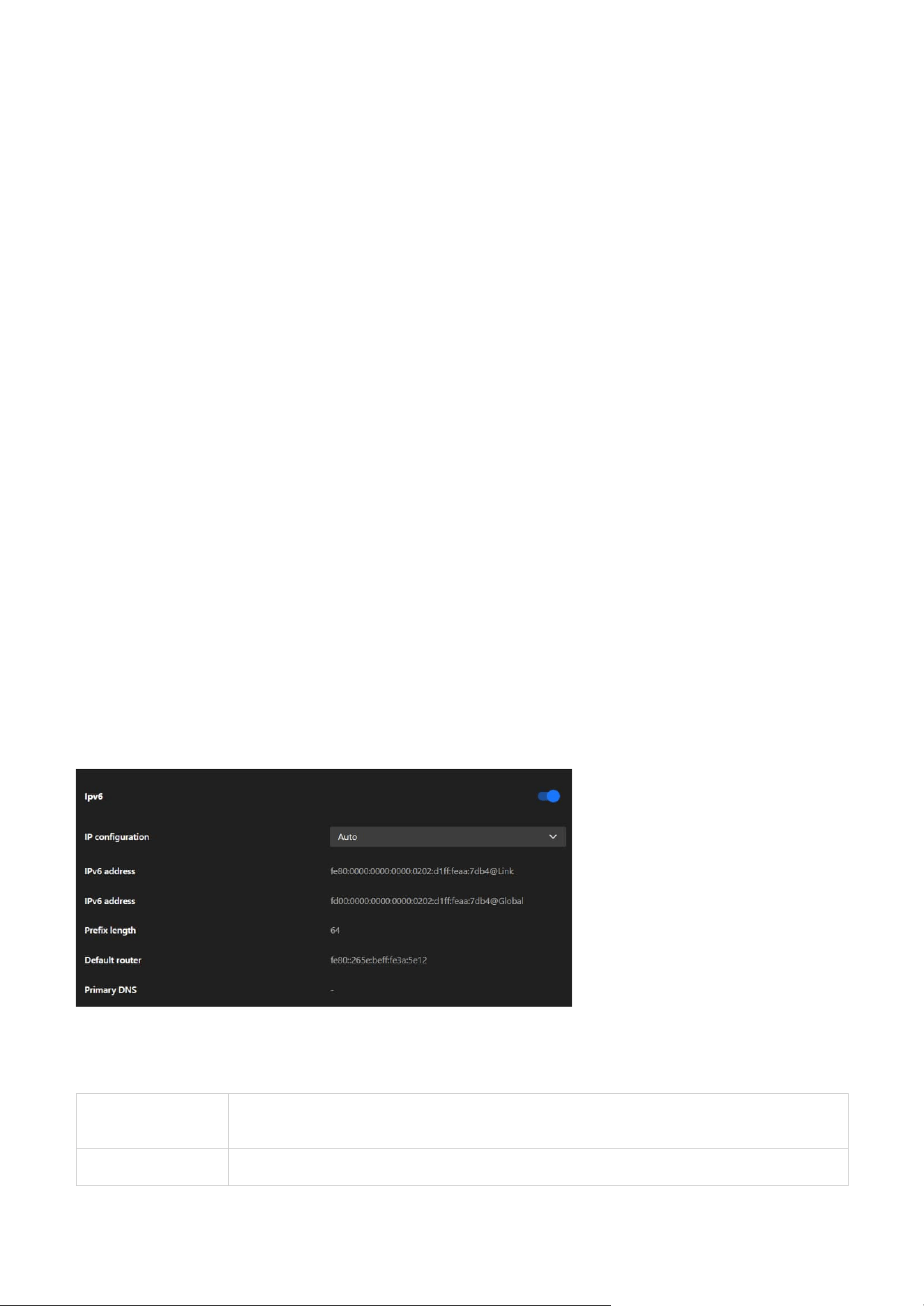
103
9 System
IPv6
The IPv6 card in the Network Settings tab equips the camera with the ability to operate in next-generation
networks, supporting automatic or manual IP address assignment, subnet configuration, and domain
name resolution. This ensures the camera is ready for modern and future network environments,
providing enhanced connectivity and adaptability.
IP Configuration
Allows the user to select how the IPv6 address is assigned:
Network Mask
Defines the subnet mask, which determines the range of devices that can directly communicate with the
camera.
Default Router
Specifies the default gateway for directing network traffic beyond the local subnet, such as accessing the
internet or external servers.
Primary and Secondary DNS
Configures DNS servers to resolve domain names into IP addresses, enabling features like remote access
using hostnames instead of IP addresses.
Primary and Secondary WINS Server
Specifies WINS servers to resolve NetBIOS names into IP addresses, typically used in Windows-based
environments to facilitate name resolution.
Enable UPnP Presentation
Select this option to enable UPnP presentation for your Network Camera so that whenever a Network
Camera is presented to the LAN, the shortcuts to connected Network Cameras will be listed in My
Network Places.
Enable UPnP Port Forwarding
To access the Network Camera from the Internet, select this option to allow the Network Camera to open
ports automatically on the router so that video streams can be sent out from a LAN. To utilize of this
feature, make sure that your router supports UPnP and it is activated.
Auto
Automatically obtains an IPv6 address using SLAAC (Stateless Address Autoconfiguration) or
DHCPv6, depending on the network setup.
Manual Enables manual input of a static IPv6 address if required.
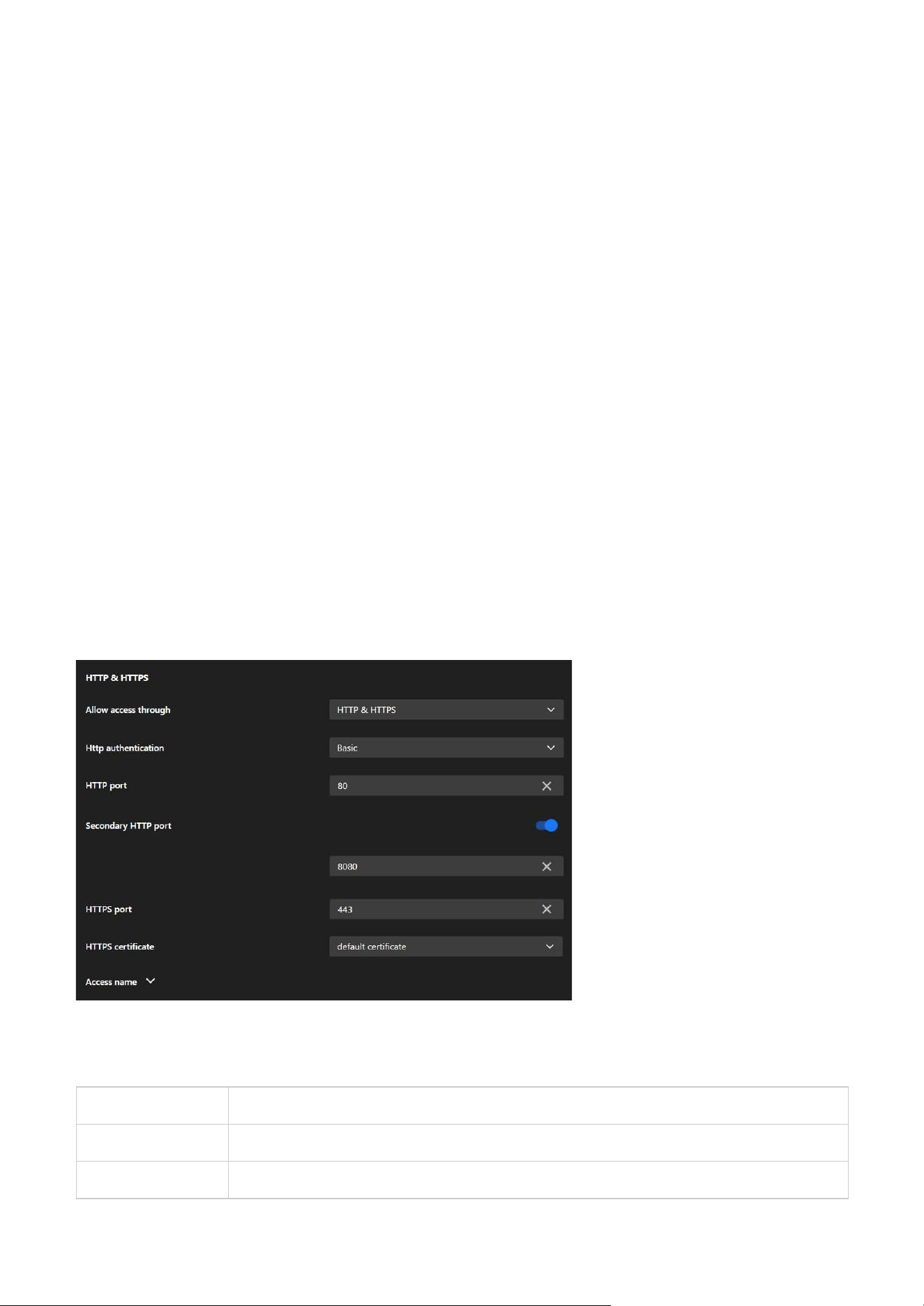
104
9 System
Protocols
HTTP & HTTPS
The Protocols tab is designed to configure various communication protocols that enable the camera to
interact with other devices, systems, and networks. It includes five key protocol cards: HTTP & HTTPS,
RTSP, SIP, SNMP, and Bonjour, each serving specific purposes for communication, streaming, and network
discovery.
The HTTP & HTTPS card is essential for configuring secure and reliable web-based access to the camera.
It provides the flexibility to use both encrypted (HTTPS) and unencrypted (HTTP) protocols, ensures
compatibility with modern security standards, and supports redundancy and customization for a variety
of deployment scenarios.
Allow Access Through
Allows users to choose the protocols for accessing the camera:
Prefix Length
Specifies the subnet prefix length, which determines the size of the subnet and the range of addresses
that can communicate directly with the camera. A prefix length of 64 is common in IPv6 configurations.
Default Router
Configures the default gateway for the camera’s outgoing traffic to external networks, ensuring
communication beyond the local IPv6 subnet.
Primary DNS
Allows the user to specify the primary DNS server to resolve domain names into IP addresses in IPv6
networks.
HTTP only Enables access via the unencrypted HTTP protocol.
HTTPS only Enables access via the encrypted HTTPS protocol.
HTTP & HTTPS Supports both protocols simultaneously for flexible access options.

105
9 System
HTTPS Certificate
Manages the digital certificate used for HTTPS communication:
• Default Certificate
Uses the camera's built-in certificate.
Access Name
Provides options to customize or manage the camera's hostname or access URL, simplifying identification
and connection.
HTTP Port
Defines the primary port used for HTTP communication (default: 80).
Secondary HTTP Port
Provides an additional HTTP port (e.g., 8080) for accessing the camera as a backup or alternative.
HTTPS Port
Sets the port for HTTPS communication (default: 443), ensuring encrypted and secure access.
TLS Version
Offers options to select the encryption protocol for HTTPS:
HTTP Authentication
Configures the authentication method for HTTP access:
Basic A simpler method that sends plain text credentials (less secure).
Digest A more secure method using hashed credentials.
TLS v1.2 only For compatibility with older systems.
TLS v1.3 only For maximum security using the latest protocol.
TLS v1.2 or v1.3 Provides flexibility by supporting both.
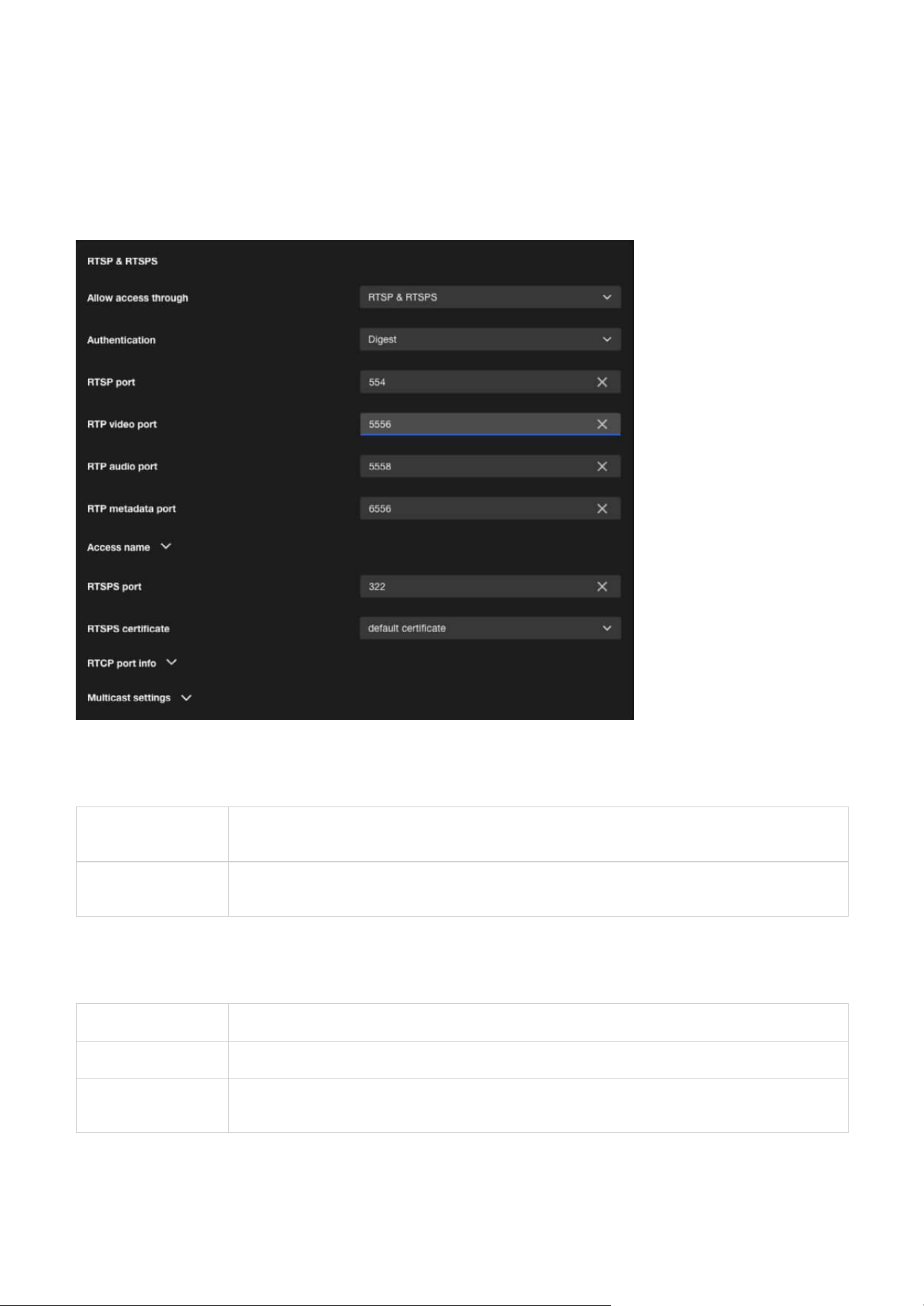
106
9 System
RTSP & RTSPS
The RTSP & RTSPS card is designed to configure real-time video and audio streaming settings for the
camera. It enables seamless integration with external systems, secure access to live feeds, and optimized
network performance through multicast and quality monitoring. This makes it a critical component for
deploying the camera in professional surveillance and media environments.
Authentication
Configures the authentication method for RTSP access:
Allow Access Through
Configures the allowed protocols for accessing video streams:
RTSP
Allows access through RTSP (unencrypted), suitable for internal networks or environments with
lower security requirements.
RTSP & RTSPS
Allows access through both RTSP (unencrypted) and RTSPS (encrypted), recommended for
external access or environments requiring enhanced security.
Disable Disables authentication, allowing unrestricted access to RTSP streams.
Basic Uses plain-text credentials for authentication (less secure, suitable for closed networks).
Digest
Employs hashed credentials for authentication, offering a more secure option for open or sensitive
environments.

107
9 System
Transport layer security
TLS Version
RTSP Port
Specifies the port number for RTSP communication (default: 554). Used for initializing RTSP sessions
between the camera and the client.
RTP Video Port
Defines the port for transmitting video streams (default: 5556).
RTP Audio Port
Specifies the port for transmitting audio streams (default: 5558).
RTP Metadata Port
Sets the port for sending metadata (e.g., timestamps or event information) along with the video and audio
streams (default: 6556).
Access Name
Provides options to configure or customize the access name (URL path) for RTSP streams, simplifying
access for third-party systems or users.
RTSPS Port
Specifies the port for secure RTSP (RTSPS) video streaming.
RTSPS Certificate
Selects the certificate used to encrypt RTSPS connections, ensuring secure video transmission.
RTCP Port Info
Configures RTCP (Real-Time Control Protocol) ports, which are used to monitor the quality of service (QoS)
of the streaming session and provide feedback on issues such as packet loss or jitter.
Multicast Settings
Divided into three sections: Video, Audio, and Metadata, each with specific settings:
Stream (for Video only)
Specifies which video stream to multicast (e.g., Stream 1 or Stream 2).
IP Version
Allows the selection of IPv4 or IPv6 for multicast traffic.
Multicast Address
Assigns a unique multicast IP address for each stream (e.g., 239.x.x.x for IPv4 or FF00::/8 for IPv6).
Multicast Port
Configures the port number for multicast streaming (e.g., 5556 for video, 5558 for audio).
Multicast TTL (Time-to-Live)
Sets the number of network hops allowed for multicast packets, controlling their distribution range.
TLS v1.2 only For compatibility with older systems.
TLS v1.3 only For maximum security using the latest protocol.
TLS v1.2 or v1.3 Provides flexibility by supporting both.
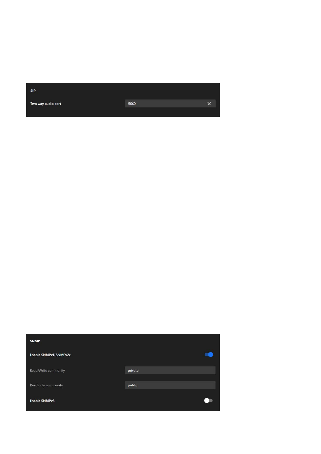
108
9 System
SIP
SNMP
This section explains how to use the SNMP on the network camera. The Simple Network Management
Protocol is an application layer protocol that facilitates the exchange of management information
between network devices. It helps network administrators to remotely manage network devices and find,
solve network problems with ease. The SNMP consists of the following three key components:
• Manager
Network-management station (NMS), a server which executes applications that monitor and control
managed devices.
• Agent
A network-management station software module on a managed device which transfers the status of
managed devices to the NMS.
• Managed device
A network node on a managed network. For example: routers, switches, bridges, hubs, computer hosts,
printers, IP telephones, network cameras, web server, and database.
Note
Before configuring SNMP settings on this card, please enable your NMS first.
Enable SNMPv1, SNMPv2c
Select the option and enter the names of Read/Write community and Read Only community according to
your NMS settings.
Two way audio port
The Two-Way Audio Port configures the port (default: 5060) used for SIP-based audio communication,
allowing the camera to transmit and receive audio streams for real-time interaction with other SIP-
compatible devices.
The SIP card is essential for configuring the camera’s two-way audio communication capabilities via the
SIP protocol. It enables integration with SIP-based systems, supports real-time audio interaction, and
ensures flexibility with customizable port settings, making it a critical feature for applications requiring
interactive communication.
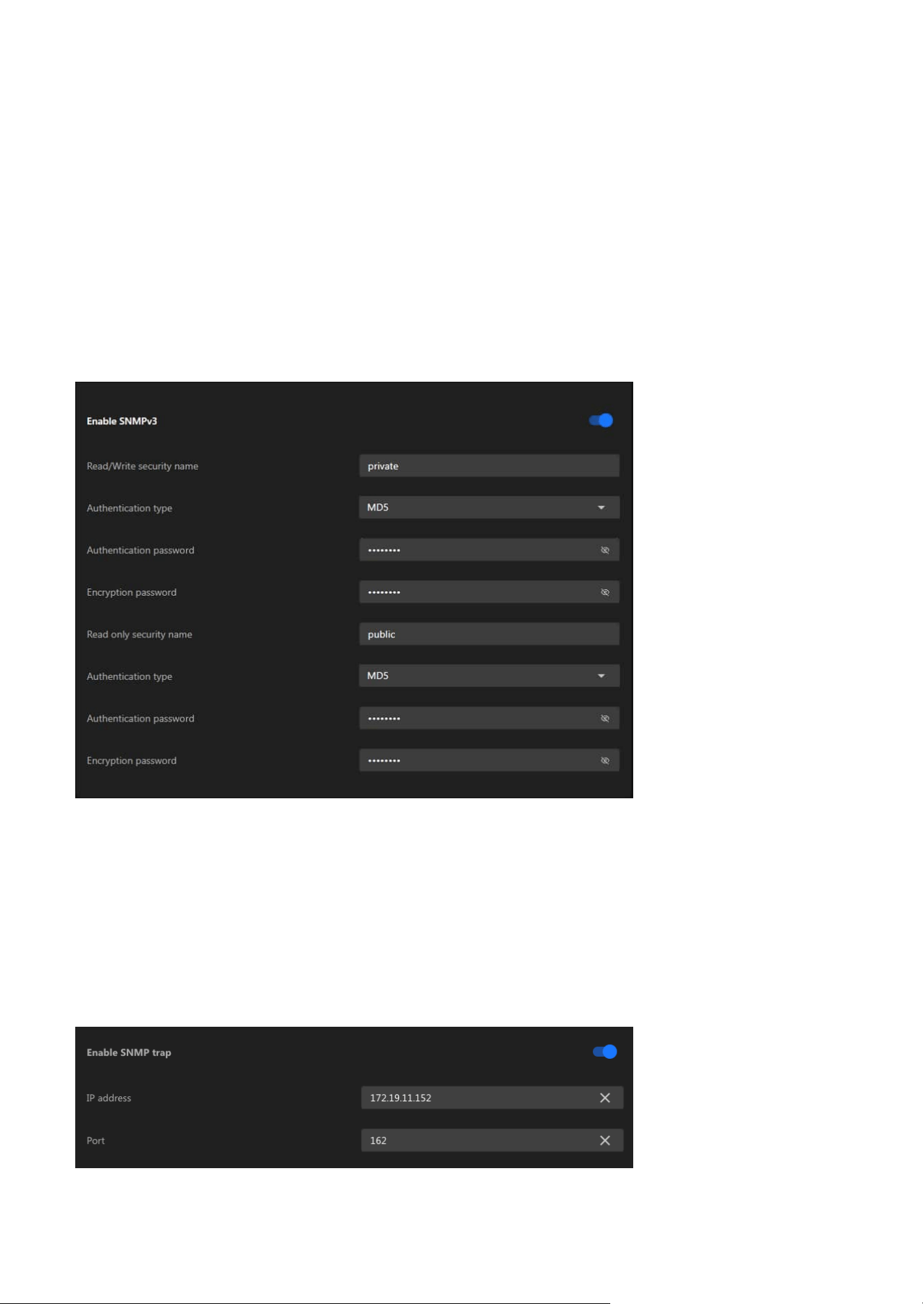
109
9 System
Enable SNMP Trap Support
The system supports a comprehensive set of SNMP traps to facilitate proactive monitoring and system
health diagnostics. These traps notify administrators of key events and system statuses, enabling timely
responses and efficient maintenance.
• IP address
Enter the IP address of the server that will receive Trap notifications.
• Port
Enter the port number for Trap notifications (default: 162).
Enable SNMPv3
This option contains cryptographic security, a higher security level, which allows you to set the
Authentication password and the Encryption password.
• Read/Write security name
According to your NMS settings, choose Read/Write or Read Only and enter the community name.
• Authentication type
Select MD5 or SHA as the authentication method.
• Authentication password
Enter the password for authentication (at least 8 characters).
• Encryption password
Enter a password for encryption (at least 8 characters).
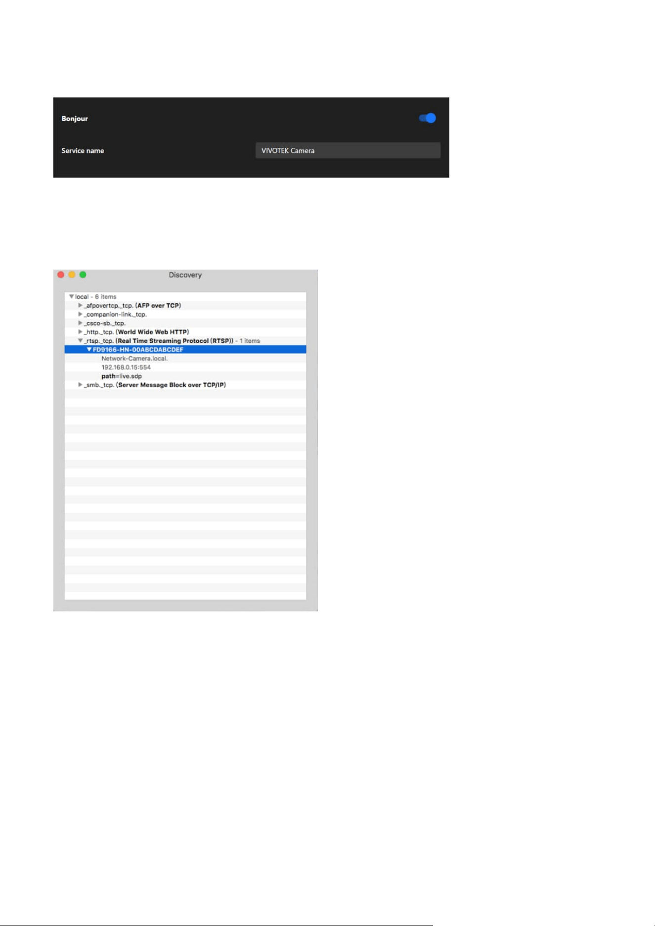
110
9 System
Bonjour
To access the camera from a MAC computer, go to Safari, click on Bonjour and select the camera from a
drop-down list.
You can go to Safari > Preferences to enter your user name and password, provide the root password the
first time you access the camera. The camera main page will open in your browser.
Discovery Utility for Bonjour Services
In some later versions of iOS, the Bonjour option may no longer be available. To address this, you can use
the Discovery utility, which serves as a replacement for the Bonjour Browser. Follow the steps below to
get started:
• Install Discovery from the Mac App Store
Discovery is a utility that lists all Bonjour services available on your local network or Wide-Area Bonjour
domains.
Previously known as Bonjour Browser, the updated Discovery utility is now distributed exclusively on
the Mac App Store.
System Requirements: Discovery requires macOS 10.12 (Sierra) or later.
http://www.tildesoft.com/files/BonjourBrowser.dmg
• Install Discovery for iOS
Discovery is also available for iOS devices and can be downloaded from the App Store.
https://itunes.apple.com/us/app/discovery-dns-sd-browser/id305441017?mt=8
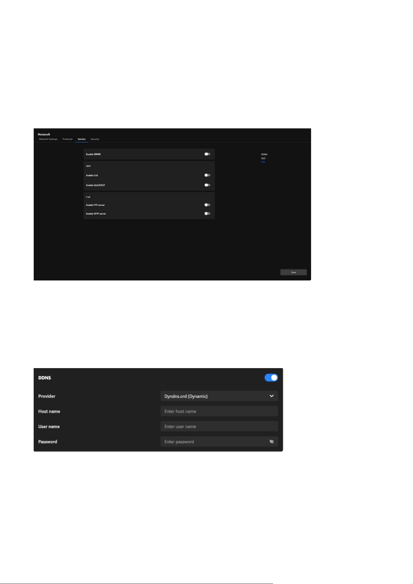
111
9 System
Service
DDNS
The Service tab provides essential options for managing network services. These include enabling
Dynamic Domain Name System (DDNS) for seamless remote access even with dynamic IP addresses,
configuring Quality of Service (QoS) settings to prioritize camera data traffic on the network, and
activating FTP or SFTP servers for secure and efficient file transfer. These features ensure reliable
connectivity, enhanced data security, and improved performance, catering to diverse surveillance
requirements.
The card integrates with third-party DDNS services to dynamically update the domain name associated
with the camera whenever its IP address changes. Users need to provide valid credentials and a
registered hostname with their DDNS provider to use this feature effectively. The difference between
"Dynamic" and "Custom" provider modes allows flexibility based on the user's DDNS service plan or
provider requirements.
Enable DDNS:
Allows the user to activate or deactivate the DDNS functionality.
Provider:
A dropdown menu allows users to select the DDNS service provider, with options such as "Dyndns.
org (Dynamic)" or "Dyndns.org (Custom)." The selected provider determines how the hostname and
credentials are configured for the DDNS connection.
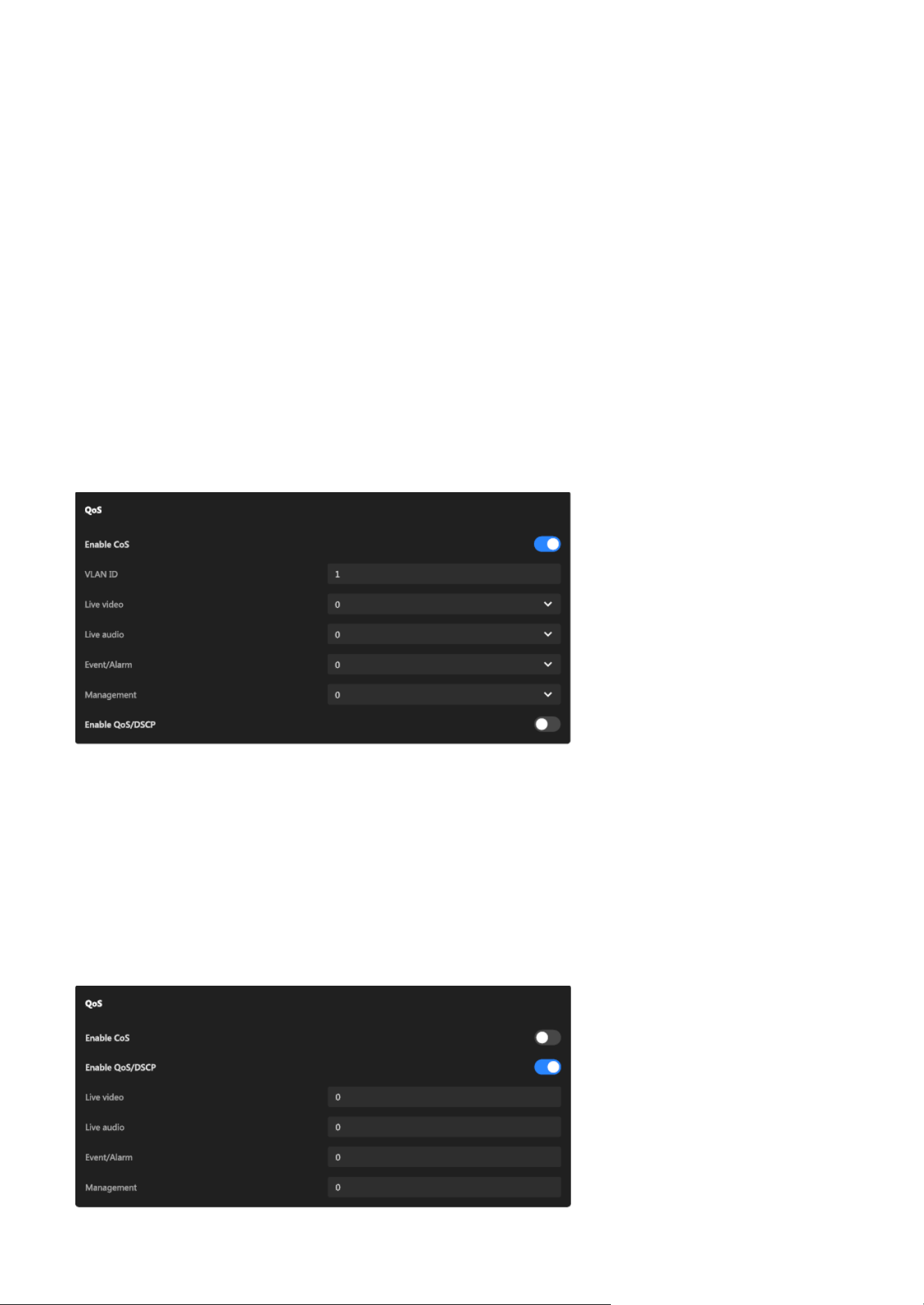
112
9 System
QoS
The QoS card allows users to flexibly configure the priority of different types of data streams based on
network environment requirements. When CoS is enabled, it can integrate with VLANs, making it suitable
for Ethernet networks. Enabling QoS/DSCP, on the other hand, is more appropriate for IP networks. These
settings help enhance the reliability and efficiency of camera data transmission, which is particularly
crucial when multiple devices share the same network.
Enable CoS (Class of Service):
A toggle switch to enable or disable CoS functionality.
VLAN ID:
Specifies the VLAN tag for identifying the virtual LAN the camera is part of.
Priority settings for each data type (Live Video, Live Audio, Event/Alarm, Management):
Each data type (Live Video, Live Audio, Event/Alarm, Management) can be assigned a priority level via a 0-7
dropdown menu, where higher numbers indicate higher transmission priority. This allows for fine-grained
control of traffic within an Ethernet network.
Host Name:
An input field is provided to specify the unique hostname registered with the selected DDNS provider (e.g.,
yourcamera.dyndns.org), which will be used for remote access to the camera.
User Name:
Input field for the account username required by the DDNS provider.
Password:
Input field for the password associated with the DDNS account. A hidden field ensures privacy during
input.
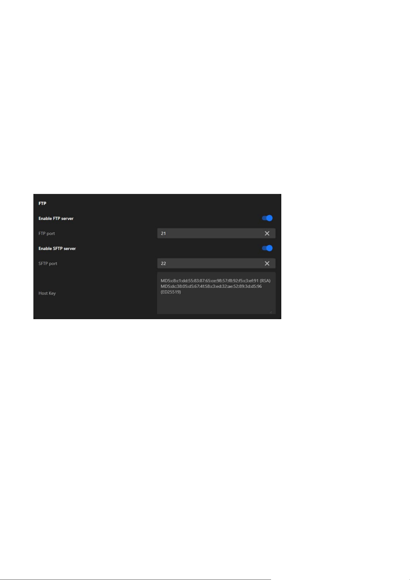
113
9 System
FTP
The FTP card provides the flexibility to use FTP for simple and efficient file transfers or SFTP for secure,
encrypted transfers, depending on the user’s operational and security needs. The ability to configure the
ports ensures compatibility with various network configurations. Host keys in SFTP further enhance trust
and security during client-server communication. This functionality is particularly useful for automated
storage or backup of surveillance data to remote locations.
Enable FTP Server:
A toggle switch to enable or disable the FTP server functionality.
FTP Port:
Specifies the port used for the FTP service (default is 21). Users can adjust this to align with their network
or security requirements.
Enable SFTP Server:
A toggle switch to enable or disable the SFTP server functionality.
SFTP Port:
Specifies the port used for the SFTP service (default is 22). Users can modify this port if needed to avoid
conflicts or meet specific security policies.
Host Key:
Displays the server's host key information, including hash values (e.g., RSA and ED25519 keys). These keys
are used to authenticate the server and ensure secure connections between the client and the server.
Enable QoS/DSCP (Differentiated Services Code Point):
A toggle switch to enable or disable DSCP functionality.
DSCP values for each data type (Live Video, Live Audio, Event/Alarm, Management):
Allows users to configure a DSCP value for each data type (Live Video, Live Audio, Event/Alarm,
Management). These values determine the priority of the data in IP networks, ensuring proper traffic
classification and efficient routing.
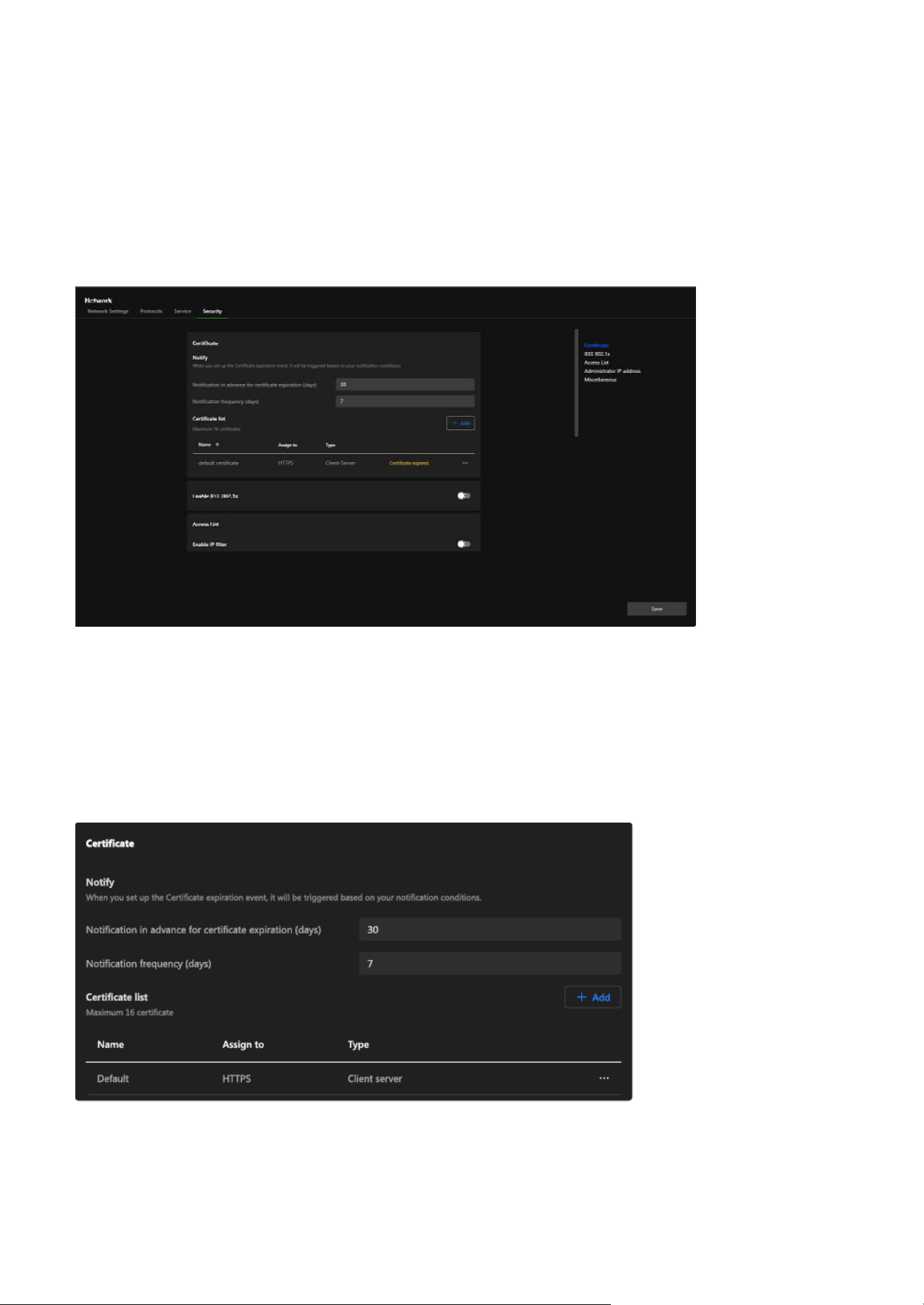
114
9 System
Security
Certificate
The Certificate card focuses on providing a robust and centralized solution for managing certificates.
By supporting HTTPS encryption, it ensures secure communication between the camera and external
systems, safeguarding data against potential eavesdropping or tampering. The notification feature alerts
users to expired certificates, helping to mitigate associated risks, while the ability to manage multiple
certificates offers flexibility to accommodate various network configurations and requirements.
The Security tab provides a comprehensive set of options to enhance network security. It allows users
to manage certificates for encrypted communications, implement access control through IP filtering
and IEEE 802.1x authentication, and restrict administrative access to specific IP addresses. By utilizing
these features, users can ensure secure data transmission, prevent unauthorized access, and protect the
camera in both simple and complex network environments. This tab is designed to address the security
needs of modern surveillance systems and offer robust protection against potential threats.
Notify:
Configures notification settings for certificate expiration.
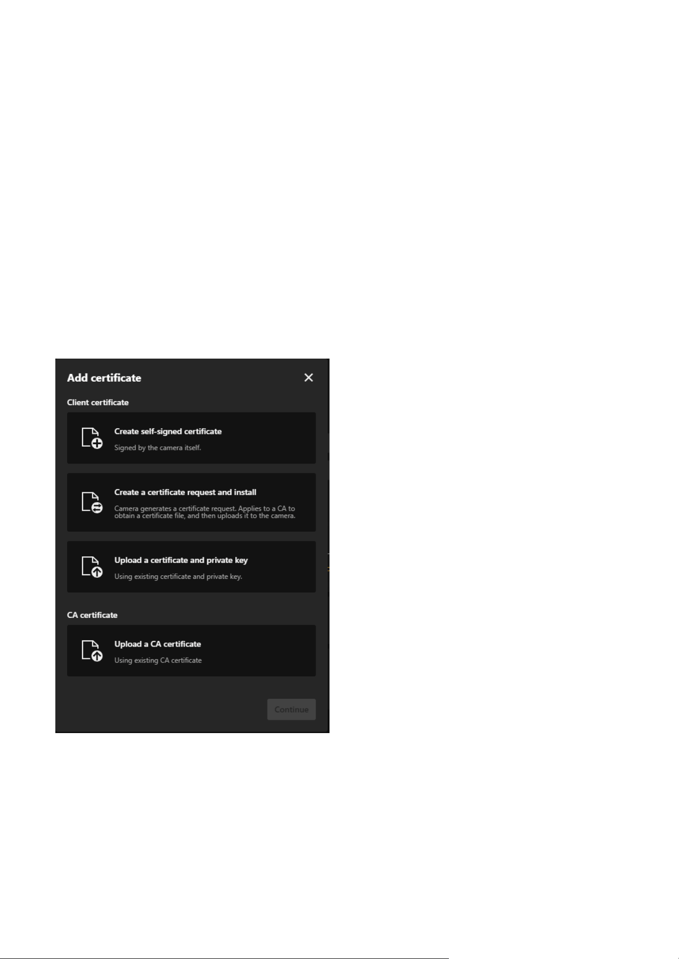
115
9 System
• Notification in advance for certificate expiration (days):
Sets how many days before expiration the system will send a notification.
• Notification frequency (days):
Specifies the frequency of repeated notifications.
Certificate List:
Supports managing up to 16 certificates and displays detailed information about each certificate,
including:
• Name:
The name of the certificate.
• Assign to:
The application or protocol the certificate is associated with (e.g., HTTPS).
• Type:
The purpose of the certificate (e.g., Client-Server).
• Indicates the current status of each certificate, such as "Certificate expired."
Steps to add a Certificate:
Option 1. Create a self-signed certificate for the Client certificate.
Step 1. Click "+Add” button and then pop up the “Add Certificate" window.
Step 2. Select Create self-signed certificate.
Step 3. Fill in the required fields, including:
• Name: Enter a name for the certificate (e.g., "Cert 01").
• Certificate country: Provide the country code (e.g., "TW").
• State or province and Locality: Specify the location (e.g., "Asia").
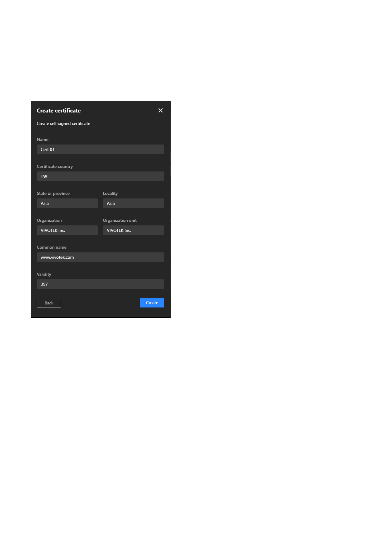
116
9 System
• Organization and Organization unit: Enter the organization details.
• Common name: Provide the domain name (e.g., "www.vivotek.com").
• Validity: Specify the validity period in days (e.g., "397").
Step 4. Click Create to start certificate generate procedure.
Step 5. A message indicating "Generated successfully" means the process is complete.
Option 2. Create a Certificate Request and Install for the Client certificate.
Step 1. Click "+Add” button and then pop up the “Add Certificate" window.
Step 2. Select Create a certificate request and install.
Step 3. Fill in the required fields similar to the self-signed certificate (Name, Location, Organization,
Common Name).
Step 4. Click Create to start certificate generate procedure.
Step 5. A message indicating "Uploaded successfully" means the certificate request is generated
successfully.
Step 6. Click “Copy certificate request” button to copy the details of the certificate request (CSR).
Step 7. Use the copied CSR to apply for a certificate from a trusted CA, which will then provide a signed
certificate file (e.g., a.crt file).
Step 8. After receiving the signed certificate from the CA, return to the same window, click Upload file,
and select the .crt file provided by the CA.
Step 9. Click Create to complete the installation of the certificate.
Step 10. A message indicating "Uploaded successfully" means the process is complete.
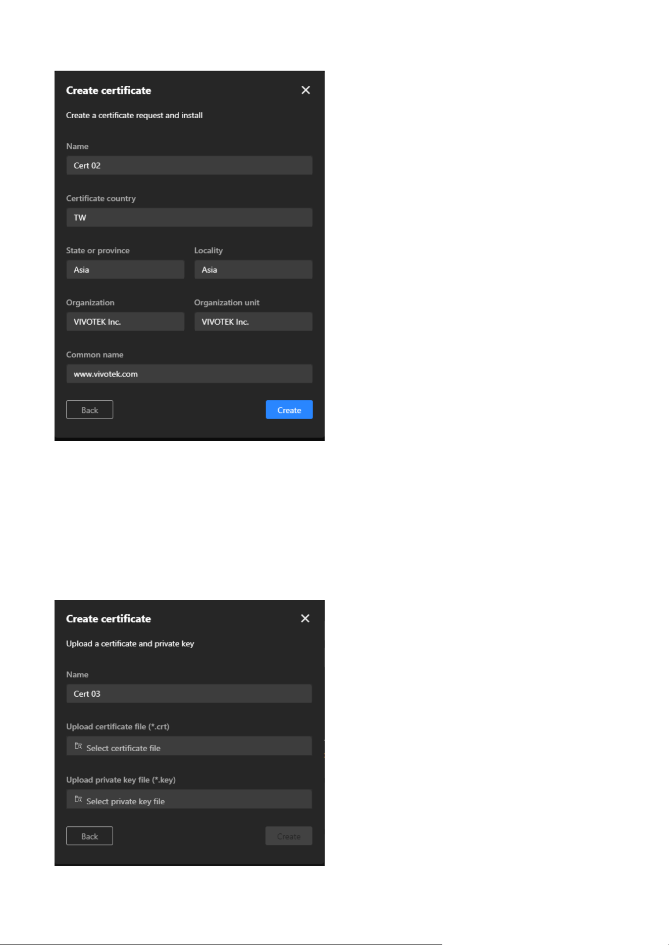
117
9 System
Option 3: Upload a Certificate and Private Key for the Client certificate.
Step 1. Click "+Add” button and then pop up the “Add Certificate" window.
Step 2. Select Upload a certificate and private key.
Step 3. Fill in the certificate name (e.g., "Cert 03").
Step 4. Use the Upload certificate file (*.crt) and Upload private key file (*.key) options to upload the
respective files.
Step 5. Click Create to add the certificate.
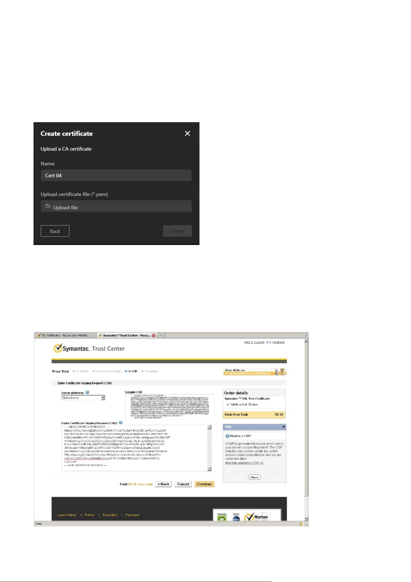
118
9 System
Note
How to use the copied CSR to apply for a certificate from a trusted CA, which will then provide a signed
certificate file:
Step 1. Look for a trusted certificate authority, such as Symantec’s VeriSign Authentication Services, that
issues digital certificates. Sign in and purchase the SSL certification service. Copy the certificate
request from your request prompt and paste it in the CA’s signing request window. Proceed with
the rest of the process as CA’s instructions on their webpage.
Option 4: Upload a CA Certificate for the CA certification
Step 1. Click "+Add” button and then pop up the “Add Certificate" window.
Step 2. Select Upload a CA certificate.
Step 3. Fill in the certificate name (e.g., "Cert 04").
Step 4. Use the Upload certificate file (*.pem) option to upload the CA certificate.
Step 5. Click Create to finalize the process.
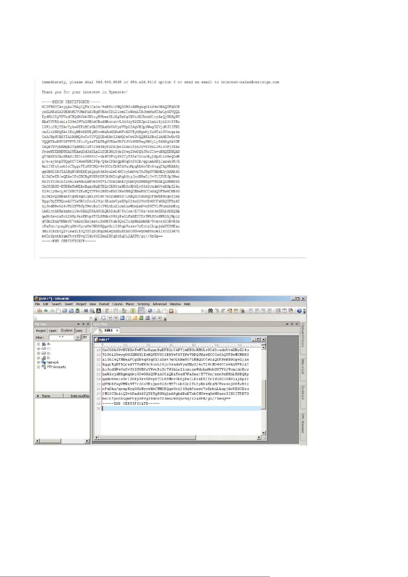
119
9 System
Step 2. Once completed, your SSL certificate should be delivered to you via an email or other means. Copy
the contents of the certificate in the email and paste it in a text/HTML/hex editor/converter, such
as IDM Computer Solutions’ UltraEdit.
Step 3. Open a new edit, paste the certificate contents, and press ENTER at the end of the contents to add
an empty line.
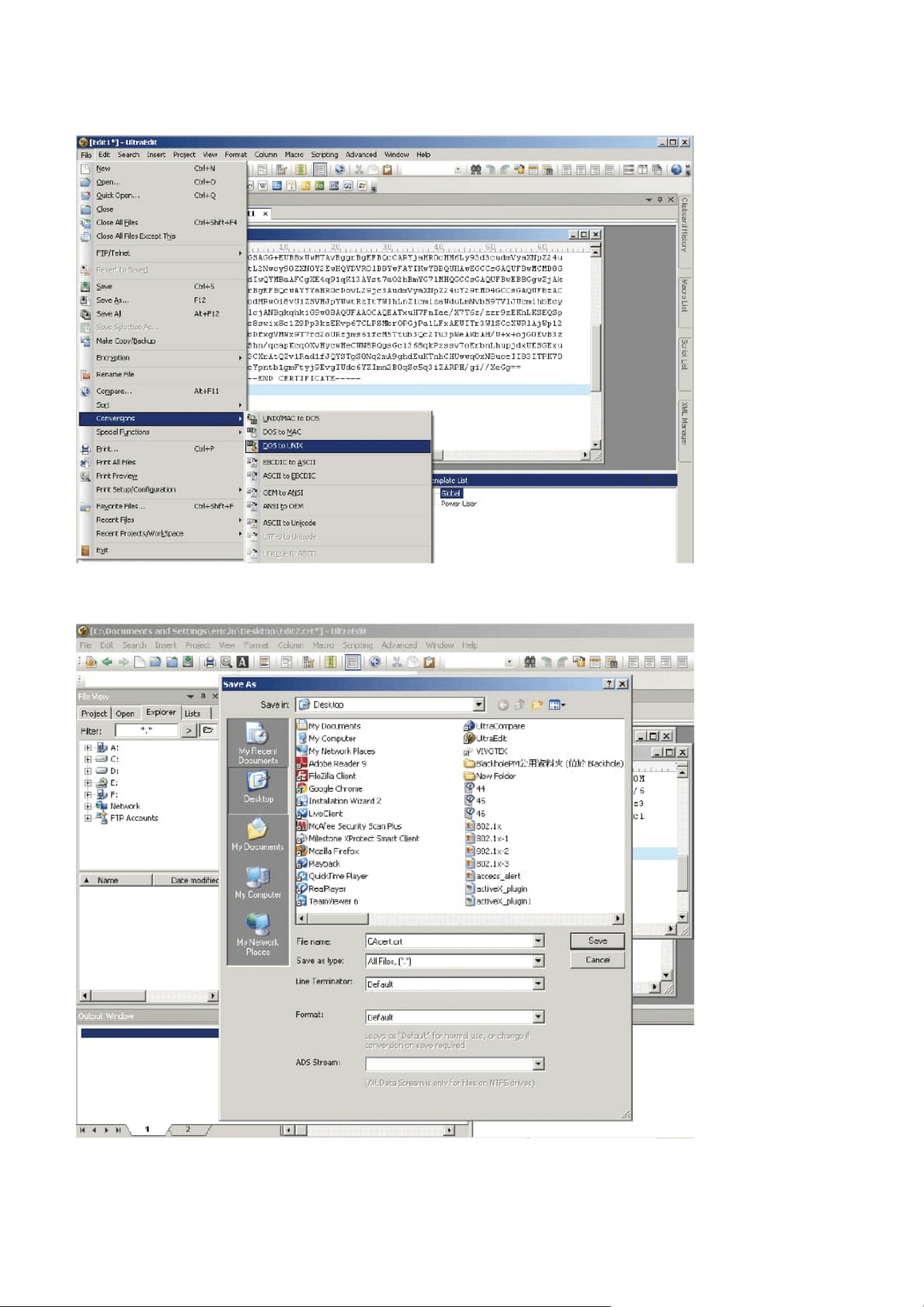
120
9 System
Step 4. Convert file format from DOS to UNIX. Open File menu > Conversions > DOS to Unix.
Step 5. Save the edit using the “.crt” extension, using a file name like “CAcert.crt.”
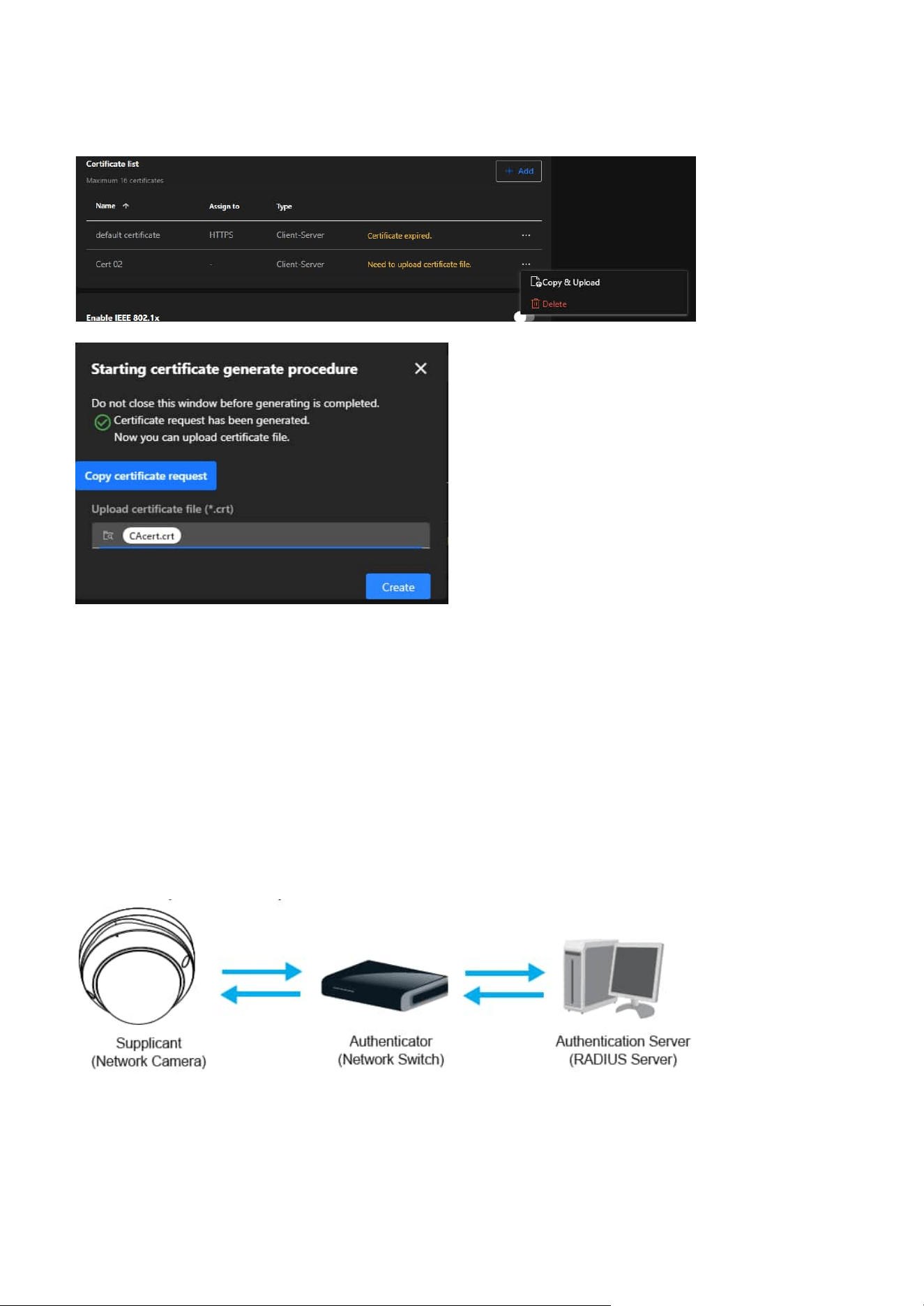
121
9 System
IEEE 802.1x
Enable this function if your network environment uses IEEE 802.1x, which is a port-based network access
control. The network devices, intermediary switch/access point/hub, and RADIUS server must support
and enable 802.1x settings.
The 802.1x standard is designed to enhance the security of local area networks, which provides
authentication to network devices (clients) attached to a network port (wired or wireless). If all certificates
between client and server are verified, a point-to-point connection will be enabled; if authentication fails,
access on that port will be prohibited. 802.1x utilizes an existing protocol, the Extensible Authentication
Protocol (EAP), to facilitate communication.
The components of a protected network with 802.1x authentication:
Step 6. Return to the original firmware session, use the “More” icon > “Copy & Upload” button to locate
the crt certificate file, and click Create to enable the certification.
• Supplicant:
A client end user (camera), which requests authentication.
• Authenticator (an access point or a switch):
A “go between” which restricts unauthorized end users from communicating with the authentication
server.
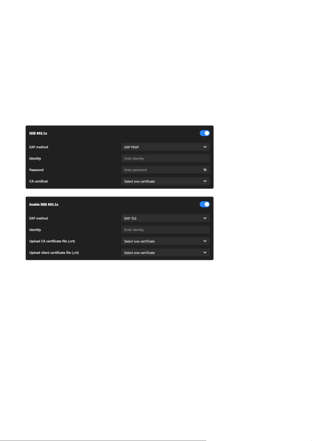
122
9 System
Step 3.
When all settings are complete, move the Network Camera to the protected LAN by connecting it
to an 802.1x enabled switch. The devices will then start the authentication automatically.
Note
The authentication process for 802.1x:
• Authentication server (usually a RADIUS server):
Checks the client certificate and decides whether to accept the end user’s access request.
VIVOTEK Network Cameras support two types of EAP methods to perform authentication: EAP-PEAP and
EAP-TLS. Please follow the steps below to enable 802.1x settings:
Step 1. Before connecting the Network Camera to the protected network with 802.1x, please apply a
digital certificate from a Certificate Authority (i.e., your network administrator) which can be
validated by a RADIUS server.
Step 2. Connect the Network Camera to a PC or notebook outside of the protected LAN. Open the
configuration page of the Network Camera as shown below. Select EAP-PEAP or EAP-TLS as the
EAP method. In the following blanks, enter your ID and password issued by the CA, then upload
related certificate(s).
Step 1. The Certificate Authority (CA) provides the required signed certificates to the Network Camera (the
supplicant) and the RADIUS Server (the authentication server).
Step 2. A Network Camera requests access to the protected LAN using 802.1X via a switch (the
authenticator). The client offers its identity and client certificate, which is then forwarded by the
switch to the RADIUS Server, which uses an algorithm to authenticate the Network Camera and
returns an acceptance or rejection back to the switch.
Step 3. The switch also forwards the RADIUS Server’s certificate to the Network Camera.
Step 4. Assuming all certificates are validated, the switch then changes the Network Camera’s state to
authorized and is allowed access to the protected network via a pre-configured port.
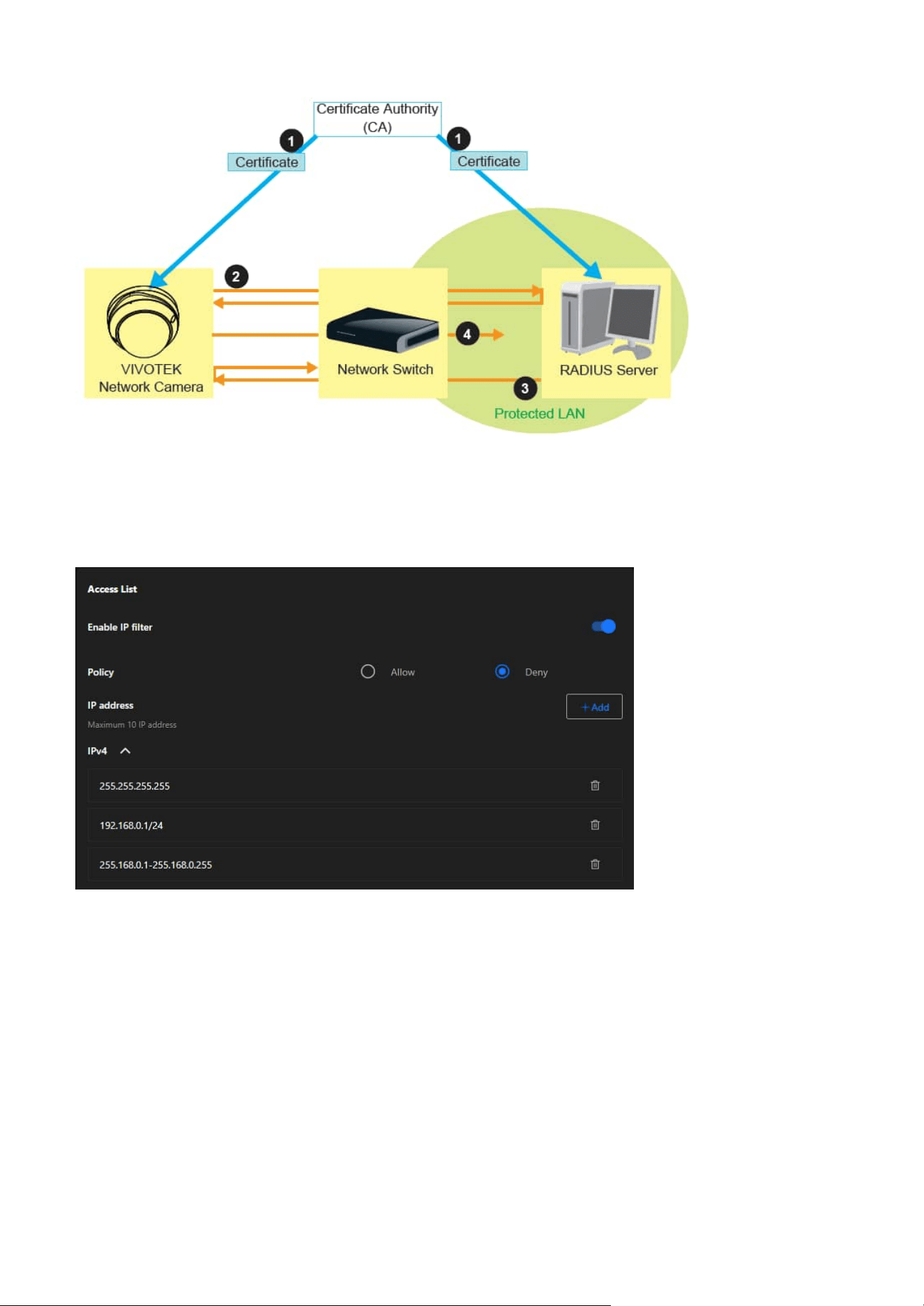
123
9 System
Access List
This feature is particularly useful in environments where the camera is exposed to a larger network or the
internet, ensuring only trusted devices or networks have access.
Enable IP Filter
A toggle switch to activate or deactivate the IP filtering feature.
Policy
• Allow:
Permits only the specified IP addresses to access the camera. All other IPs are denied.
• Deny:
Blocks the specified IP addresses from accessing the camera. All other IPs are allowed.
IP Address
A section to define up to 10 IP addresses or ranges that are either allowed or denied access based on the
selected policy.
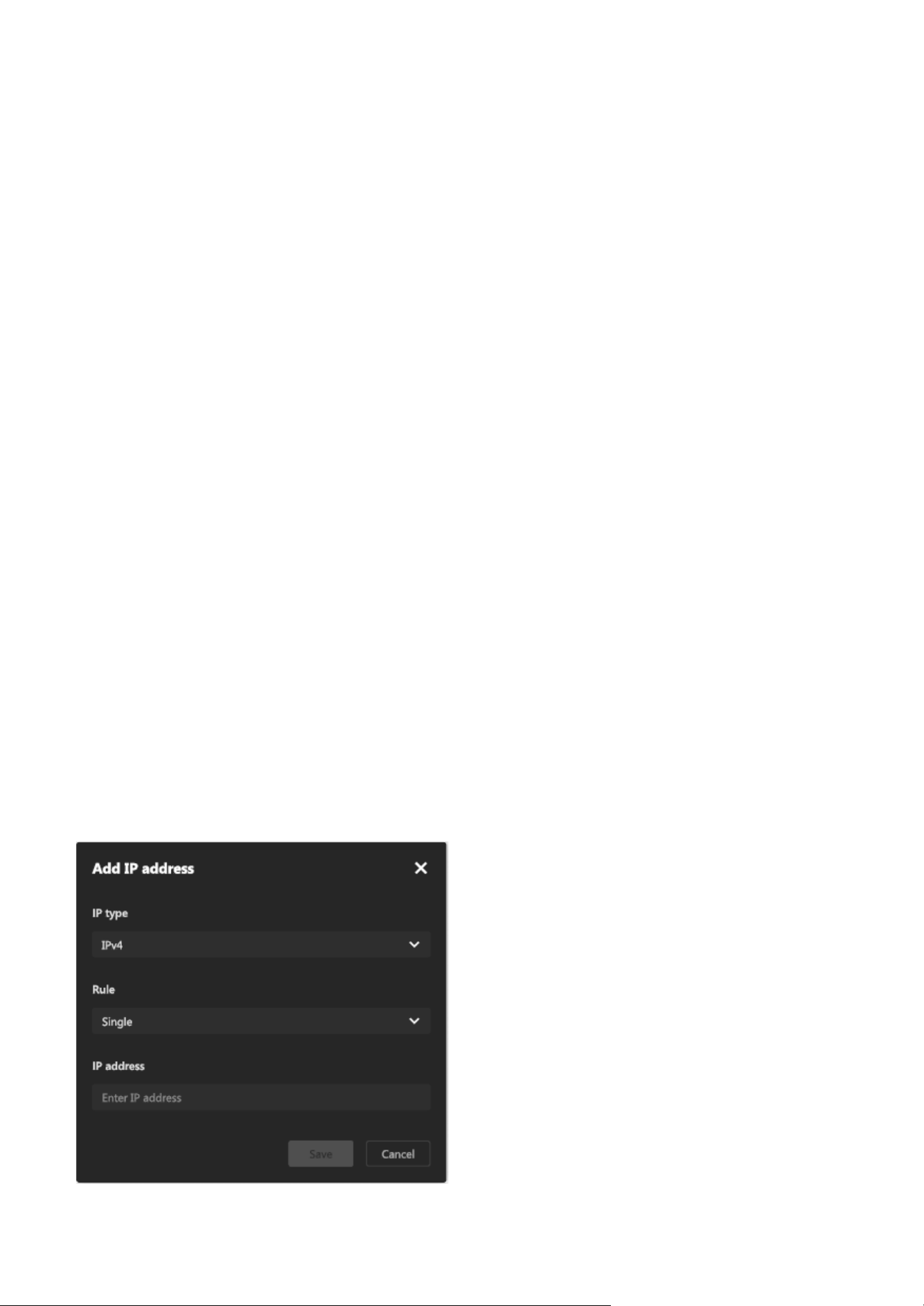
124
9 System
Steps to add an IP address into Access List:
Step 1. Click “+Add” button to open the "Add IP Address" window
Step 2. From the IP Type dropdown menu, choose the desired type:
• IPv4:
For standard IPv4 addresses or ranges.
Step 3. From the Rule dropdown menu, select one of the following options:
• Single:
To allow or deny a single IP address.
• Network:
To allow or deny access for an entire subnet.
• IP Range:
To define a specific range of IP addresses.
Step 4. Enter the IP Address:
Based on the selected rule, input the relevant details in the IP Address field:
• For Single:
Enter one IP address (e.g., 192.168.0.10).
• For Network:
Enter an IP address and its subnet mask.
• For IP Range:
Enter the starting and ending IP addresses.
Step 5. Click Save to add the IP address or range to the Access List.
Step 6. The new entry will now appear in the IPv4 section of the Access List.
IPv4 List
Displays the list of configured IP addresses or ranges, and the entries can be removed using the trash bin
icon next to each address. Each entry can represent:
• A single IP address (e.g., 192.168.0.1).
• A network IP address (e.g., 192.168.0.1/24).
• A specific IP range (e.g., 255.168.0.1-255.168.0.255).
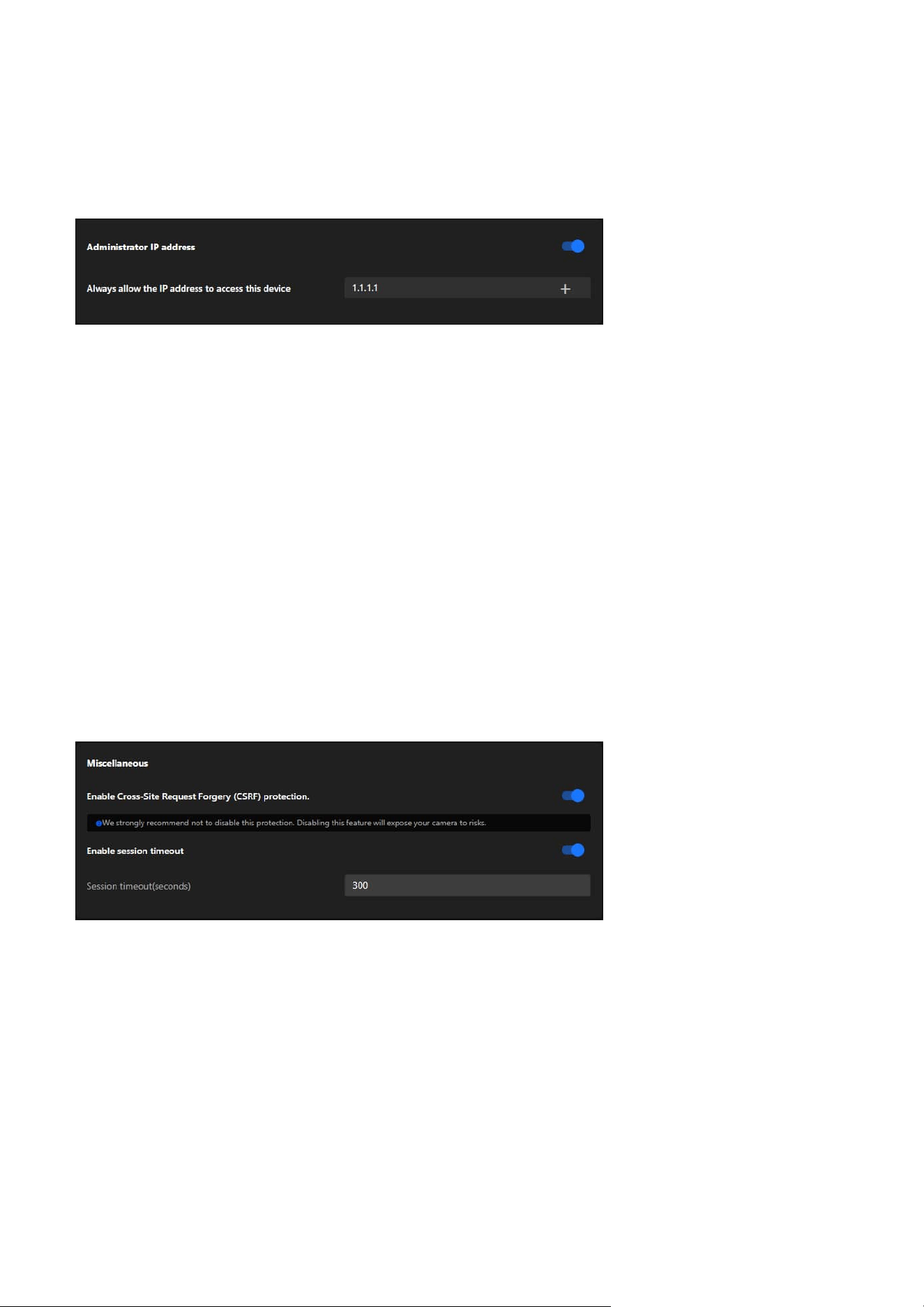
125
9 System
Administrator IP address
Miscellaneous
Always allow the IP address to access this device:
You can check this item and add the Administrator’s IP address in this field to make sure the Administrator
can always connect to the device.
Steps to set the Administrator IP address:
Step 1. Input the Trusted IP Address:
Enter the IP address that should always have administrative access.
Step 2. Enable the Feature:
Turn on the toggle switch to activate the setting.
Step 3. Save Changes:
Ensure the configuration is saved for the setting to take effect.
The Administrator IP address provides a simple yet effective way to secure administrative access while
ensuring that authorized personnel can always manage the device, even in complex or restricted network
environments.
The Miscellaneous card in the VIVOTEK camera's settings provides additional security-related options to
enhance the safety and usability of the device. It focuses on protecting against cross-site request forgery
(CSRF) attacks and managing session timeouts for user accounts.
Enable Cross-Site Request Forgery (CSRF) Protection:
Prevents unauthorized commands being sent from a malicious website to the camera on behalf of an
authenticated user.
Note
It is strongly recommended not to disable this feature, as disabling it could expose the camera to
significant security risks.
Enable Session Timeout:
Automatically logs out a user after a defined period of inactivity to prevent unauthorized access.
• Session Timeout (seconds):
Input field to specify the duration (in seconds) before the session times out. Default value: 300 seconds (5
minutes).
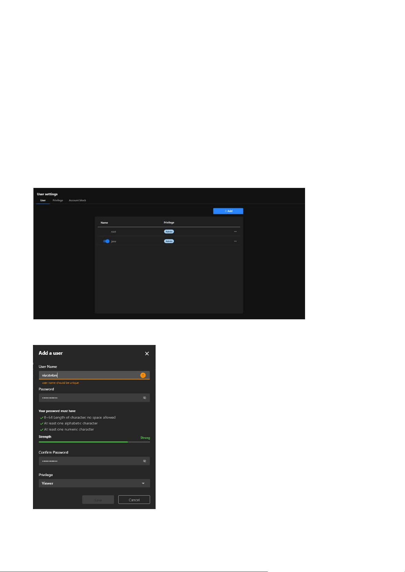
126
9 System
Manage User Access and Permissions for Enhanced
Security and Control
User
The User Accounts is critical for managing access to the VIVOTEK camera. It allows the system
administrators to create and control user accounts, define permissions, and enforce security measures
such as account blocking, ensuring that the camera is secure, manageable, and accessible only by
authorized users.
The User card provides essential tools for managing user accounts, ensuring secure access, and assigning
appropriate privileges. It helps maintain a controlled environment by enabling administrators to define
roles, monitor user activity, and enhance security for the camera system.
Steps to add a User account:
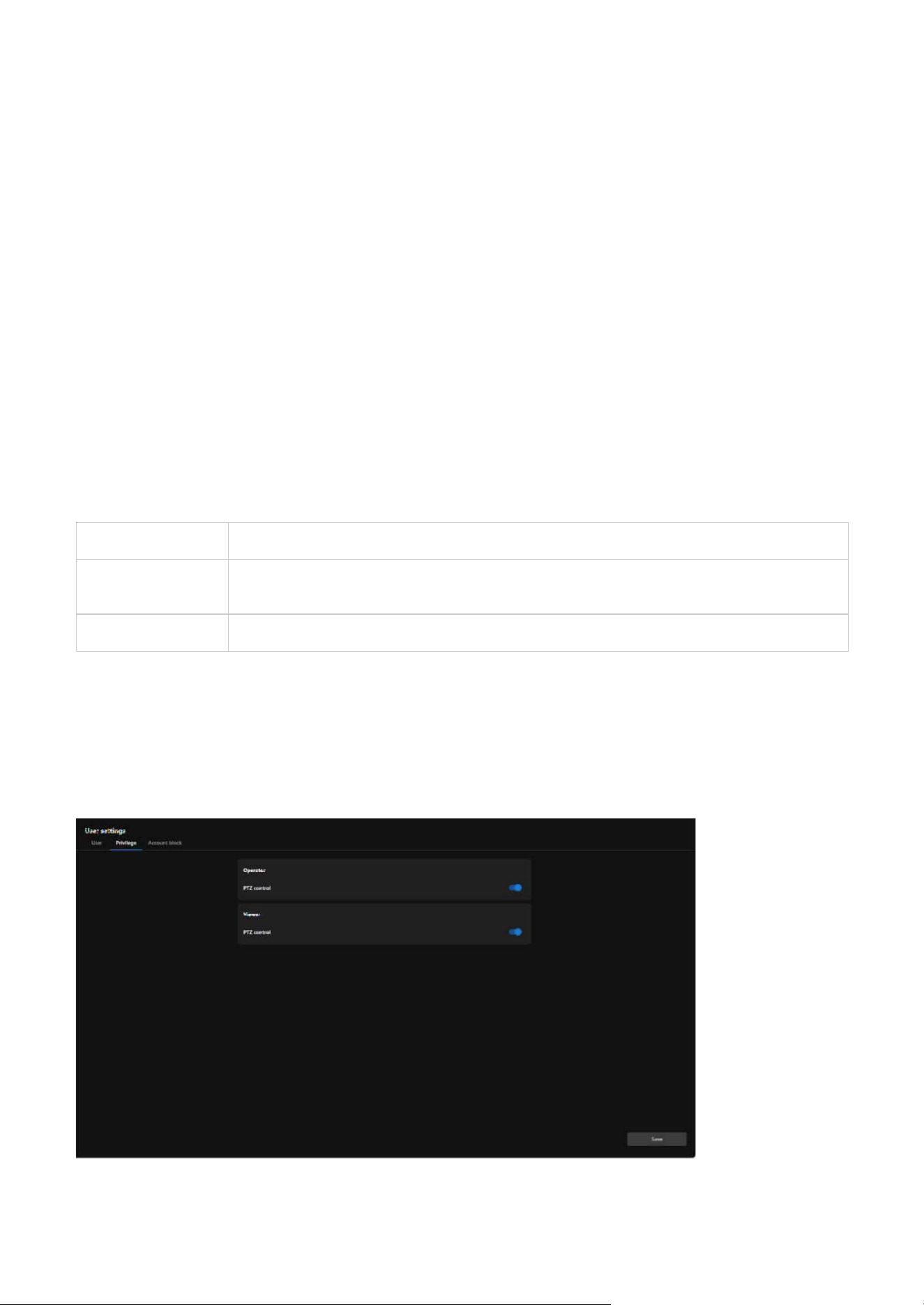
127
9 System
Administrator Full control.
Operator
Control DO, white-light illuminator, snapshot, and PTZ; unable to enter the camera Configuration
page.
Viewer Control DO, white-light illuminator, view, listen, PTZ, and talk through the camera interface.
Privilege
The Privilege card in the User Accounts section allows administrators to manage the specific privileges
assigned to different user roles. This ensures fine-grained control over what actions users can perform,
particularly for users with restricted access levels such as Operator or Viewer.
Step 1. Click on the “+ Add” Button
Locate and click the + Add button to open the “Add a User” form.
Step 2. Enter the User Name
Input a unique username in the User Name field.
Note
The username must not duplicate any existing account name.
Step 3. Set the Password
• Input a password in the Password field that meets the following criteria:
• 8–64 characters in length (no spaces allowed).
• Contains at least one alphabetic character.
• Contains at least one numeric character.
• Ensure the password strength bar indicates Strong for optimal security.
Step 4. Confirm the Password
Re-enter the password in the Confirm Password field to verify it matches.
Step 5. Assign a Privilege Level
Select the desired privilege level for the new user from the Privilege dropdown menu:
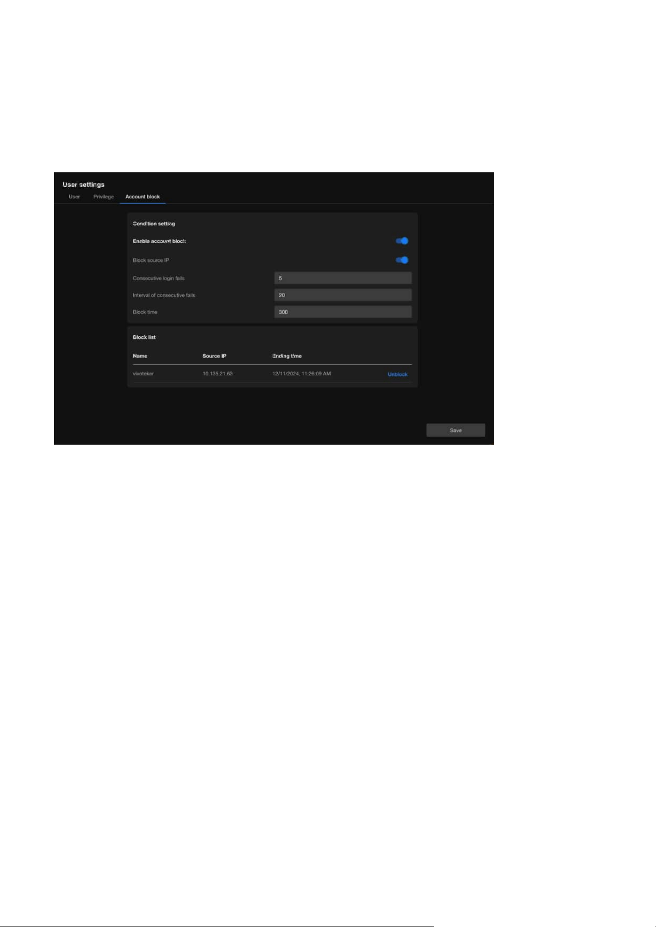
128
9 System
Account block
The Account Block is a crucial security feature that helps administrators automatically block suspicious
login attempts, effectively preventing brute force attacks and enhancing system security. Through flexible
condition settings and blocklist management, this feature ensures the camera system remains stable and
secure in multi-user environments.
Condition Setting
• Enable Account Block
Activates or deactivates the account block feature. When enabled, the system automatically blocks
suspicious login attempts based on the defined conditions.
• Block Source IP
Blocks the IP address responsible for excessive failed login attempts, restricting further access attempts
from that source.
• Consecutive Login Fails
Specifies the number of consecutive failed login attempts that trigger the block. For example, if set to 5,
an IP address will be blocked after 5 consecutive failed login attempts.
• Interval of Consecutive Fails
Defines the time frame (in seconds) within which consecutive failed attempts are counted as a trigger
for blocking.
• Block Time
Sets the duration (in seconds) for which the offending IP address will remain blocked. For example, if set
to 300 seconds, the IP address will be unable to attempt further logins for 5 minutes.
Block List
• Displays a list of currently blocked IP addresses or user accounts:
• Name: Shows the username affected by the block.
• Source IP: Indicates the IP address that triggered the block.
• Ending Time: Displays the exact time when the block will expire.
• Unblock:
Allows administrators to manually remove a blocked IP or account from the list.
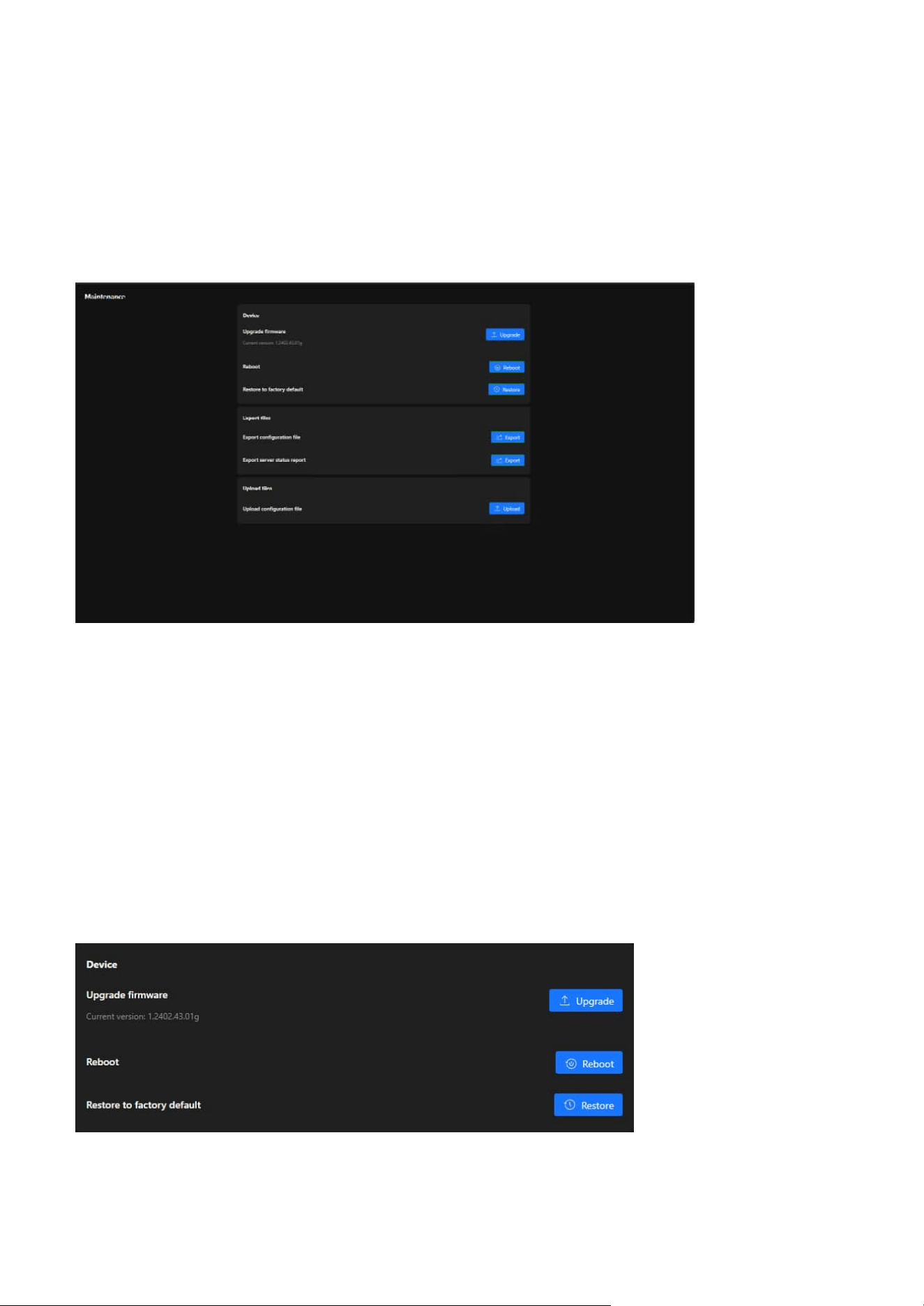
129
9 System
Firmware Updates and Configuration Management for
System Maintenance
Maintenance
Device
The Maintenance offers a centralized hub for managing firmware updates, backing up and restoring
configurations, and resetting the system to factory defaults. These tools ensure the VIVOTEK camera
operates efficiently, stays updated, and is easy to manage for administrators overseeing surveillance
systems.
The Maintenance page under the System category provides tools for managing the device's firmware,
configuration, and operational stability. This section enables administrators to perform essential
maintenance tasks to ensure the camera functions optimally. Below is a breakdown of its functionality
and purpose:
The Device card provides tools for firmware updates, system reboots, and factory resets. These functions
ensure the camera remains updated, functional, and ready for new configurations or troubleshooting
when necessary.
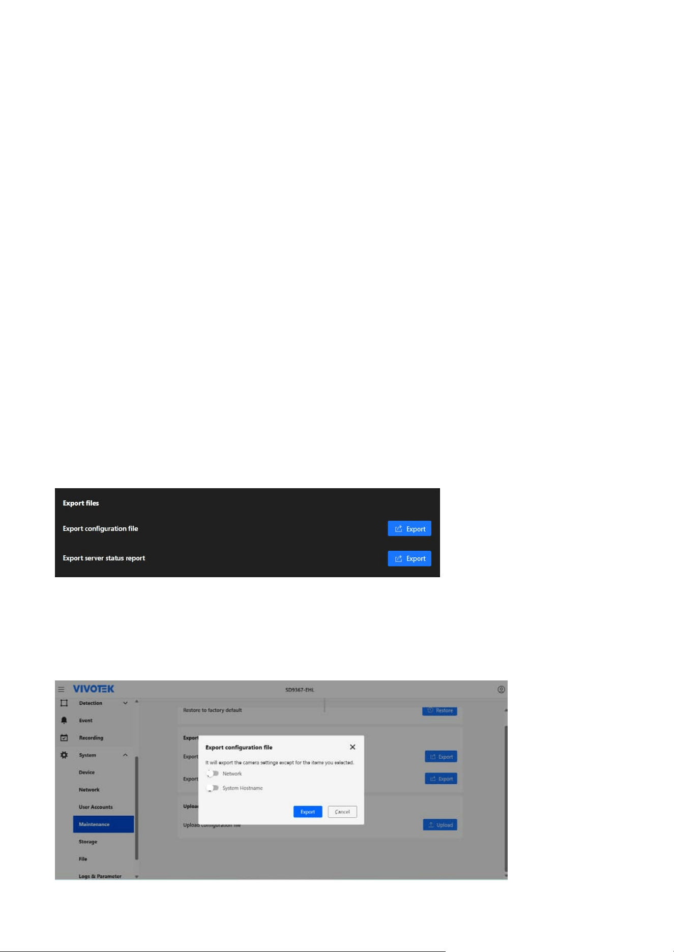
130
9 System
Export files
The Export Files card is designed to provide administrators with tools to export important data from
the camera, such as configuration settings and status reports. These features help in creating backups,
diagnosing issues, or replicating settings across multiple devices.
Export Configuration File
Creates a backup of the current camera configuration settings. This file can be used to:
• Restore the camera settings if needed.
•
Replicate the same configuration on other cameras for consistency in deployment.
Upgrade Firmware
Keeps the camera up to date with the latest features, performance improvements, and security patches.
Ensures compatibility with new technologies and enhanced system functionality.
Displayed Information:
Current firmware version (e.g., 1.2402.43.01g) is shown for reference.
Action:
Clicking the Upgrade button allows users to upload a new firmware file and update the device.
Reboot
Restarts the camera to refresh its system processes without altering configurations. Useful for applying
changes or resolving temporary issues.
Action:
Clicking the Reboot button triggers a restart of the camera.
Restore to Factory Default
Resets the camera to its original factory settings, removing all custom configurations. This option is useful
for troubleshooting persistent issues or preparing the device for redeployment.
Action
Clicking the Restore button clears all configurations and restores default settings.

131
9 System
Optimized Storage Solutions for Reliable Video Recording
and Data Retention
Upload files
The Storage section offers a comprehensive suite of tools to manage and optimize the camera's storage
resources. Whether utilizing internal memory, SD cards, or external NAS devices, this section ensures
reliable video recording and efficient data retention. With features like cyclic storage, reserved space
settings, and automatic cleanup, administrators can ensure continuous operation and maximize storage
capacity effortlessly.
The Upload Files card allows administrators to restore or apply preconfigured settings to the camera
by uploading a configuration file. This feature is particularly useful for system recovery or deploying
standardized configurations across multiple devices.
Upload Configuration File
This function enables the restoration of the camera's settings using a previously exported configuration
file, simplifying the replication of configurations across multiple cameras and speeding up recovery in
cases of system resets or data loss.
Action:
Clicking the Upload button allows users to select a configuration file from their local system and apply it
to the camera.
Action:
In the Export configuration file dialog, select whether to exclude Network and System Hostname from
the export. This option is especially useful when preparing configuration files for large-scale batch
imports. Clicking Export downloads the configuration file to the local system.
Export Server Status Report
Generates and exports a report containing the camera's operational status, including diagnostics and
logs. This is useful for:
• Analyzing performance and identifying potential issues.
• Sharing status information with support teams or system administrators for troubleshooting.
Action:
Clicking the Export button downloads the server status report for further analysis.
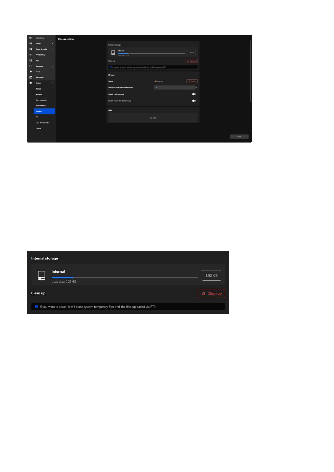
132
9 System
Storage Settings
Internal storage
The Storage settings is designed to manage storage devices and optimize the storage space used for video
recording, file saving, and system operations. This section provides administrators with tools to monitor,
clean, and configure storage options, ensuring the camera operates efficiently and retains critical data.
The Internal storage card is designed to manage and monitor the camera's internal memory usage. It
provides an overview of the storage capacity, current usage, and tools for maintaining storage efficiency
by removing unnecessary files.
Storage Overview
• Displayed Information:
• Total Capacity: Displays the total storage capacity of the internal memory (e.g., 1.92 GB).
• Used Size: Indicates the amount of storage currently being used (e.g., 0.27 GB).
• Usage Bar: Visually represents the proportion of used and available storage.
Clean Up
Frees up internal storage by deleting unnecessary files, such as:
• System temporary files.
• Files uploaded via FTP.
Action:
Clicking the Clean Up button initiates the cleanup process, clearing the designated files and making more
space available for important data.
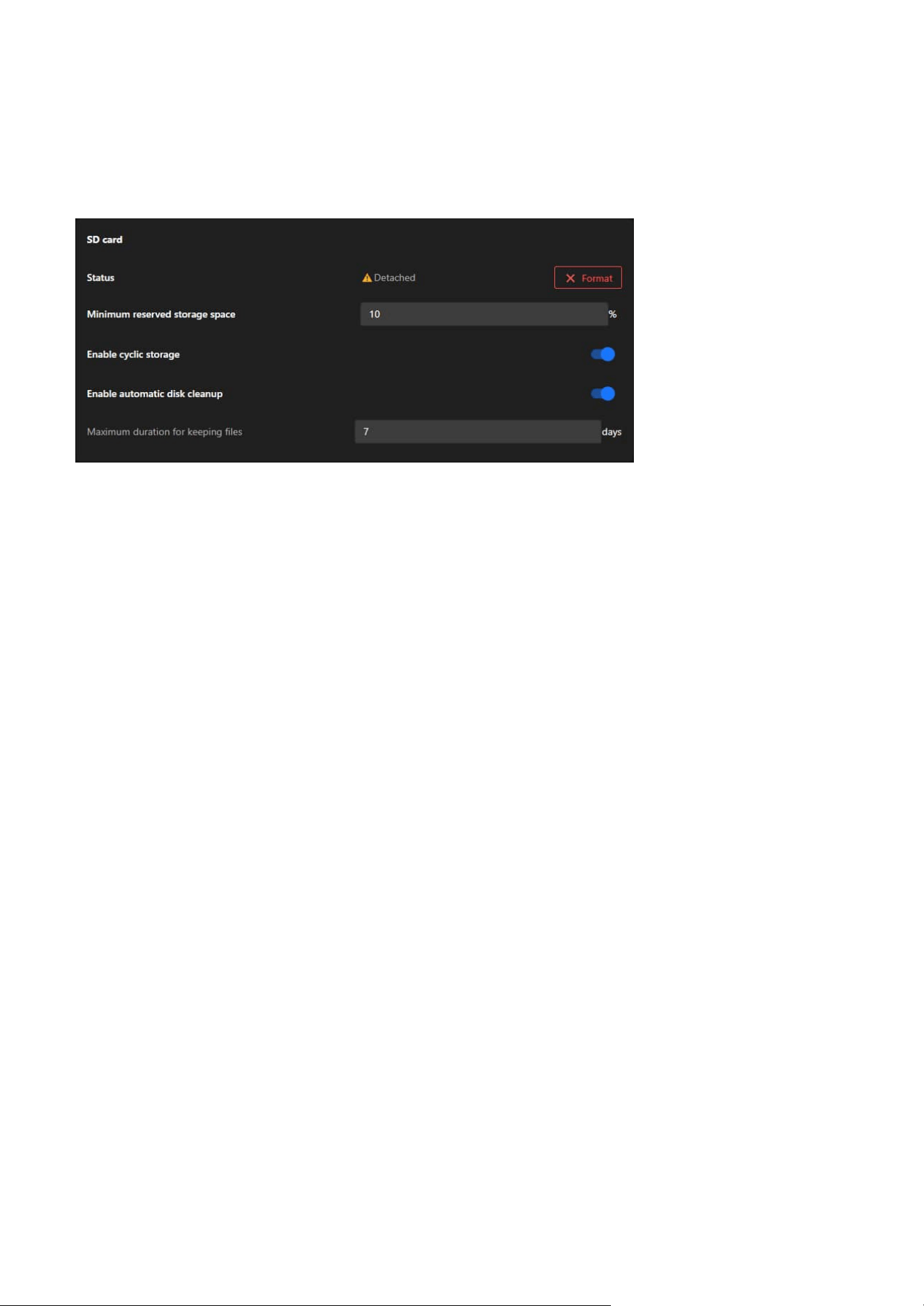
133
9 System
SD card
The SD card allows administrators to manage and monitor the SD card's usage, status, and settings. This
functionality is crucial for ensuring reliable data storage and maintaining continuous video recording or
file saving.
Status
Displays the current status of the SD card (e.g., "Detached" if no card is inserted or recognized).
Actions:
Use the Format button to erase all files and initialize the SD card for use.
Minimum Reserved Storage Space
Reserves a percentage of the SD card's total capacity to prevent it from being entirely filled, ensuring
critical operations can continue.
Actions:
Enter a percentage (e.g., 10%) to reserve storage space.
Enable Cyclic Storage
Enables automatic overwriting of the oldest data on the SD card when it is full, ensuring continuous
recording.
Actions:
Toggle this feature on or off to control storage behavior.
Enable Automatic Disk Cleanup
Automates the deletion of unnecessary or older files to free up storage space.
Dependency:
Enabling this feature activates the Maximum Duration for Keeping Files option.
Actions:
Toggle this feature on to allow automatic cleanup of outdated files.
Maximum Duration for Keeping Files
Sets a specific retention period for files on the SD card (e.g., 7 days). Files older than the specified duration
are deleted automatically.
Actions:
Input the desired number of days for file retention in the text box.
To Prepare the SD Card:
Step 1. Insert an SD card into the camera’s slot.
Step 2. Check the Status field to confirm the SD card is detected.
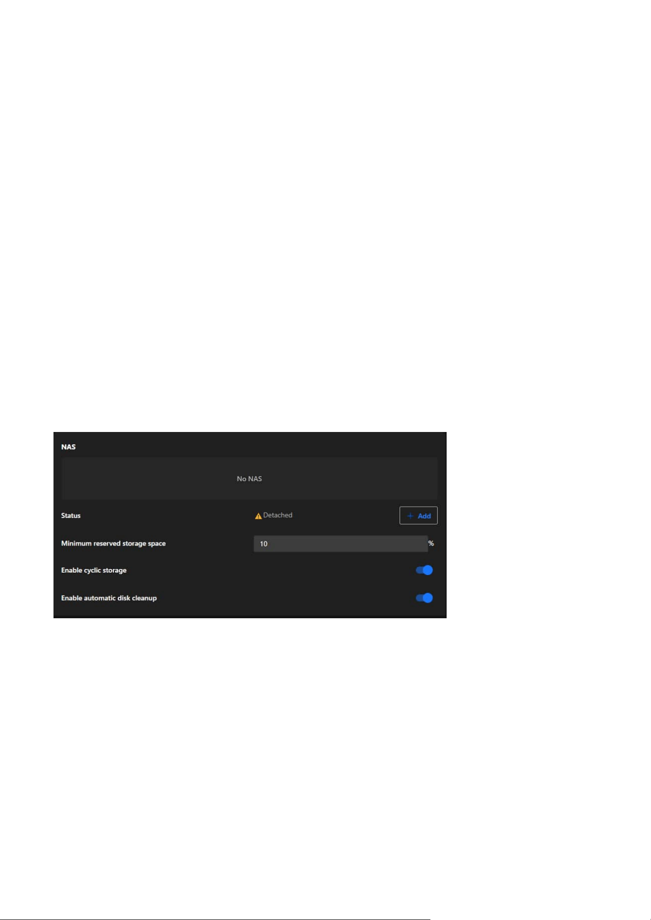
134
9 System
NAS
The NAS card allows administrators to integrate a Network Attached Storage (NAS) device for extended
and scalable storage. This feature ensures that the camera's storage capacity can be expanded and data
can be securely stored in a centralized location.
To Ensure Continuous Recording:
Step 1. Confirm both Enable Cyclic Storage and Enable Automatic Disk Cleanup are activated.
Step 2. Regularly check the Status to ensure the SD card is functioning properly.
To Configure Storage Settings:
Step 1. Set the Minimum Reserved Storage Space:
• Input a percentage (e.g., 10%) to reserve part of the SD card’s capacity.
Step 2. Toggle Enable Cyclic Storage:
• Turn this feature on to allow the oldest files to be overwritten when the SD card is full.
Step 3. Enable Automatic Disk Cleanup (Optional):
• Toggle this option to activate cleanup functions.
• Input the Maximum Duration for Keeping Files (e.g., 7 days) to define the file retention period.
Step 3. If the SD card is new or needs reinitialization:
Click the Format button to erase its contents and prepare it for use.
NAS Status
Displays the connection status of the NAS device (e.g., "Detached" if no connection is established).
Actions:
Click + Add to configure and connect a NAS device.
Minimum Reserved Storage Space
Ensures that a defined percentage of the NAS storage remains reserved to prevent the system from filling
the NAS entirely.
Actions:
Administrators can input a percentage (e.g., 10%) to reserve storage space for critical use.
Enable Cyclic Storage
Allows the camera to overwrite the oldest files stored on the NAS when the storage is full, ensuring
uninterrupted recording.
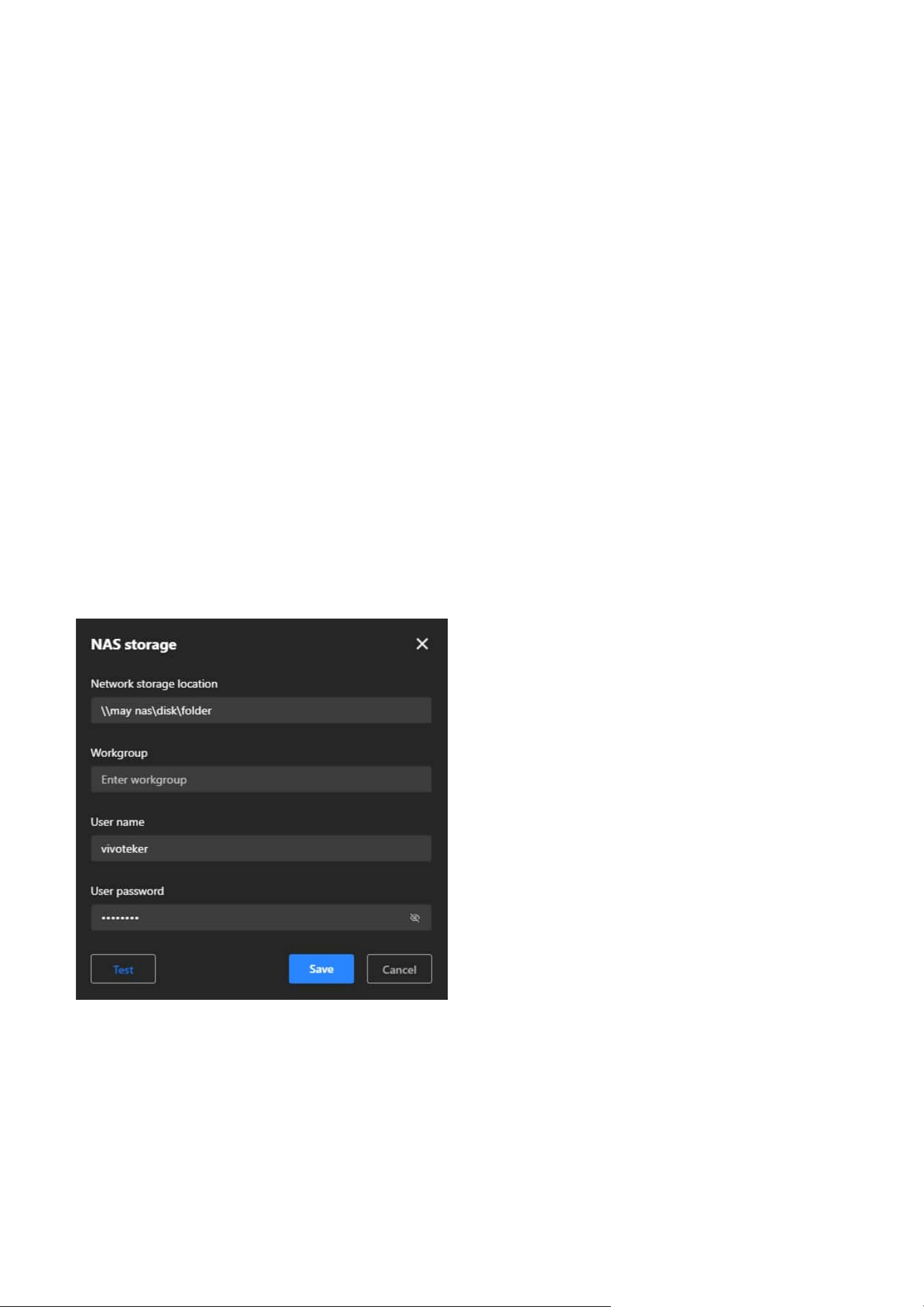
135
9 System
NAS Configuration Steps
Step 1. Open NAS Storage Settings:
Click + Add in the NAS card to open the configuration window.
Step 2. Set Network Storage Location:
Enter the path to the NAS storage folder (e.g., \\NASDevice\SharedFolder).
Step 3. Enter Workgroup (Optional):
If required, specify the workgroup to which the NAS device belongs.
Step 4. Provide User Credentials:
Input the Username and Password needed to authenticate and access the NAS device.
Step 5. Test the Connection:
Click Test to ensure the camera can successfully connect to the specified NAS location.
Step 6. Save Configuration:
Click Save to apply the settings and establish the connection.
Actions:
Toggle this feature on or off depending on the storage management preferences.
Enable Automatic Disk Cleanup
Automates the cleanup of outdated or unnecessary files stored on the NAS to maintain sufficient
available space.
Actions:
Toggle this feature on to activate automatic file deletion based on system-defined criteria.
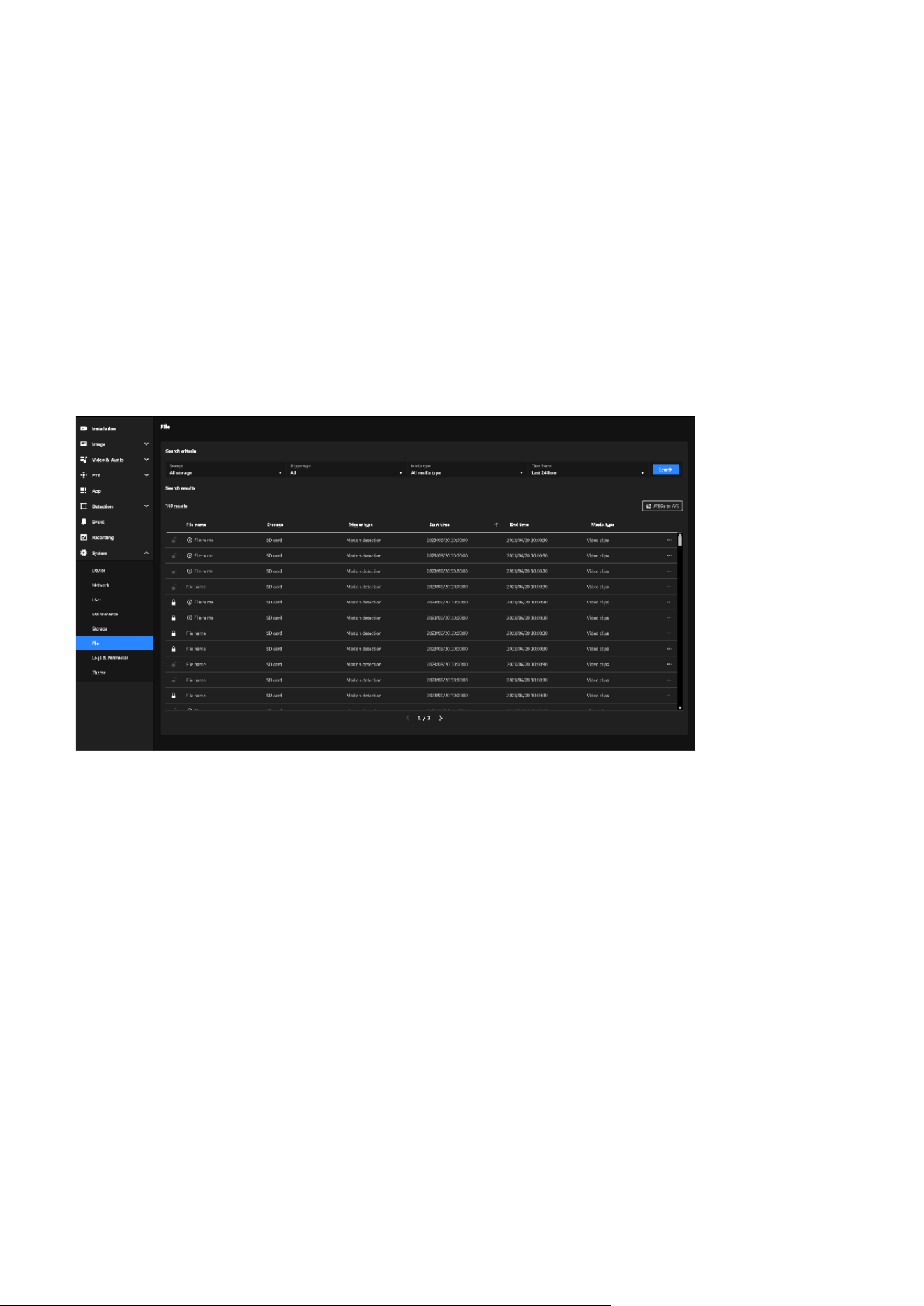
136
9 System
Effortless Management and Retrieval of Recorded Media
File
The File section offers a user-friendly interface for managing recorded media files. With search and
filtering tools, users can locate specific recordings based on storage type, trigger events, media format,
and time frame. It also allows locking files, exporting recordings, and converting media for efficient
handling and preservation. This ensures organized storage and quick access to important data.
The File section enables users to efficiently search, filter, and manage recorded media files. Key features
include advanced search criteria, file locking for data retention, and options to export or convert
recordings. Its primary purpose is to streamline media organization, ensure secure storage, and support
quick access for detailed analysis.
Search criteria
Allows users to refine their search for recorded files based on specific parameters, making it easier to
locate relevant recordings.
• Search Filters:
• Storage: Filter by storage type (e.g., SD card, NAS, or all storage devices).
• Trigger Type: Search for files triggered by specific events (e.g., motion detection, manual recording).
• Media Type: Filter by the type of media (e.g., video clips, snapshots).
• Time Frame: Specify a time range (e.g., last 24 hours, custom time range) to narrow the search.
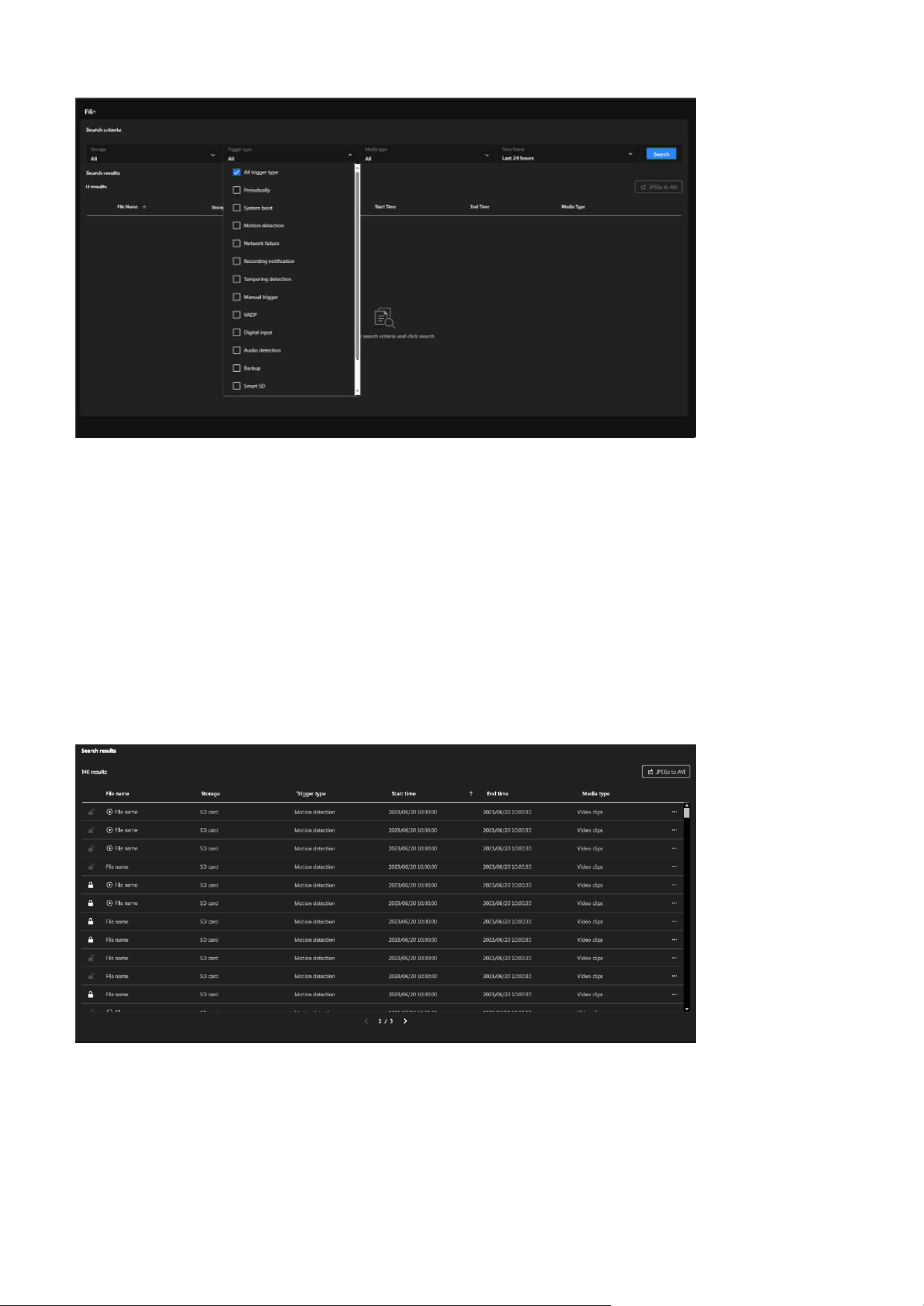
137
9 System
Note:
• File Lock/Unlock button:
Locked files, identified by a lock icon, are protected from automatic deletion, and their retention can be
managed using the lock/unlock button.
• Play button:
Only files with recorded data and playback permission will display the Play button.
Search Results
• File Name:
Name of the recorded file.
• Storage:
Indicates the storage location of the file (e.g., SD card).
• Trigger Type:
Shows the event that triggered the recording (e.g., motion detection).
• Start and End Time:
Provides the time range for each recording.
• Media Type:
Specifies the type of media file (e.g., video clips).
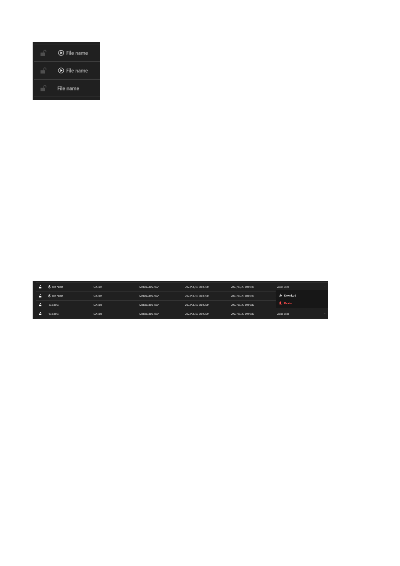
138
9 System
File Options (More icon)
Each file in the results has additional options accessible via the three-dot menu:
• Download:
Allows you to save the file to your local device.
Steps:
Step 1. Click the three-dot menu next to a file.
Step 2. Select Download.
Step 3. The file will be saved to your default download location.
• Delete:
Permanently removes the file from the storage.
Steps:
Step 1. Click the three-dot menu next to a file.
Step 2. Select Delete.
Step 3. Confirm the deletion in the pop-up prompt.
JPEGs to AVI
The JPEGs to AVI functionality allows users to convert sequential JPEG image snapshots into a playable
AVI video format. This feature is particularly useful for scenarios where users need to review footage as a
continuous video instead of analyzing individual images.
Steps to Use JPEGs to AVI:
Step 1. Click “JPEGs to AVI” button.
Step 2. Selection Feature Activation:
A checkbox is displayed next to each snapshot file, allowing users to manually select which files to
include in the AVI conversion.
Step 3. Two new buttons appear:
• Combine
This button allows the user to confirm and initiate the conversion process. It is enabled only
after at least one file is selected.
• Cancel
Clicking this button exits the conversion mode, clearing all selections and restoring the original
file view.
Step 4. Start combining into a single AVI file.
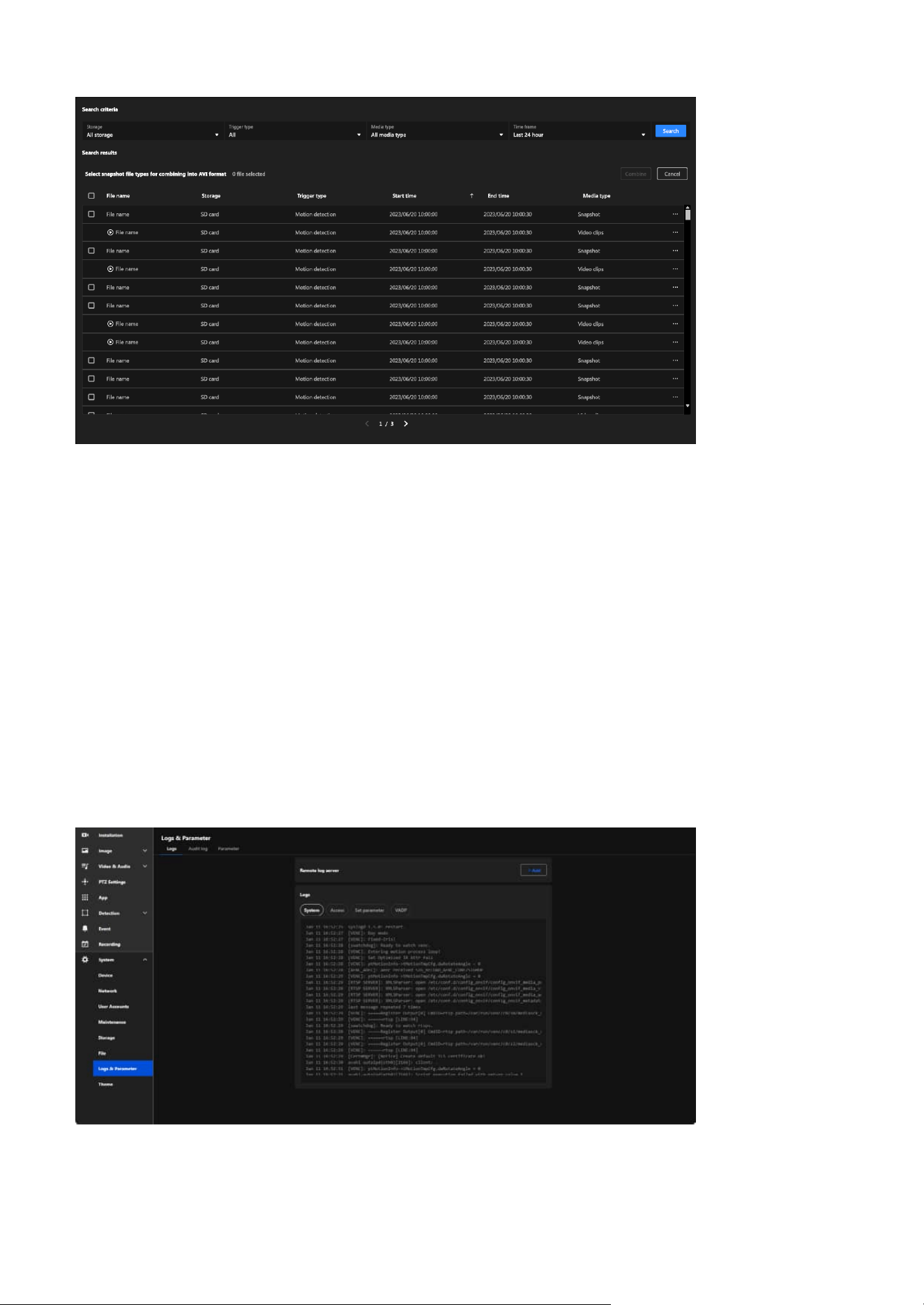
139
9 System
Monitoring and Managing System Logs and Parameters
Logs & Parameter
Effective system management relies on the ability to monitor and analyze detailed logs and parameters.
This section provides tools to view and manage system, access, and configuration logs, enabling users to
diagnose issues, track activity, and maintain optimal performance. With features like remote log server
integration and parameter management, this chapter equips administrators with the necessary controls
to ensure security and operational efficiency in both standalone and multi-camera setups.
The Logs & Parameter section in the VIVOTEK camera's system settings is designed to provide detailed
insights into system events, user activity, and configuration changes. It facilitates troubleshooting,
monitoring, and maintaining the overall performance and security of the camera.
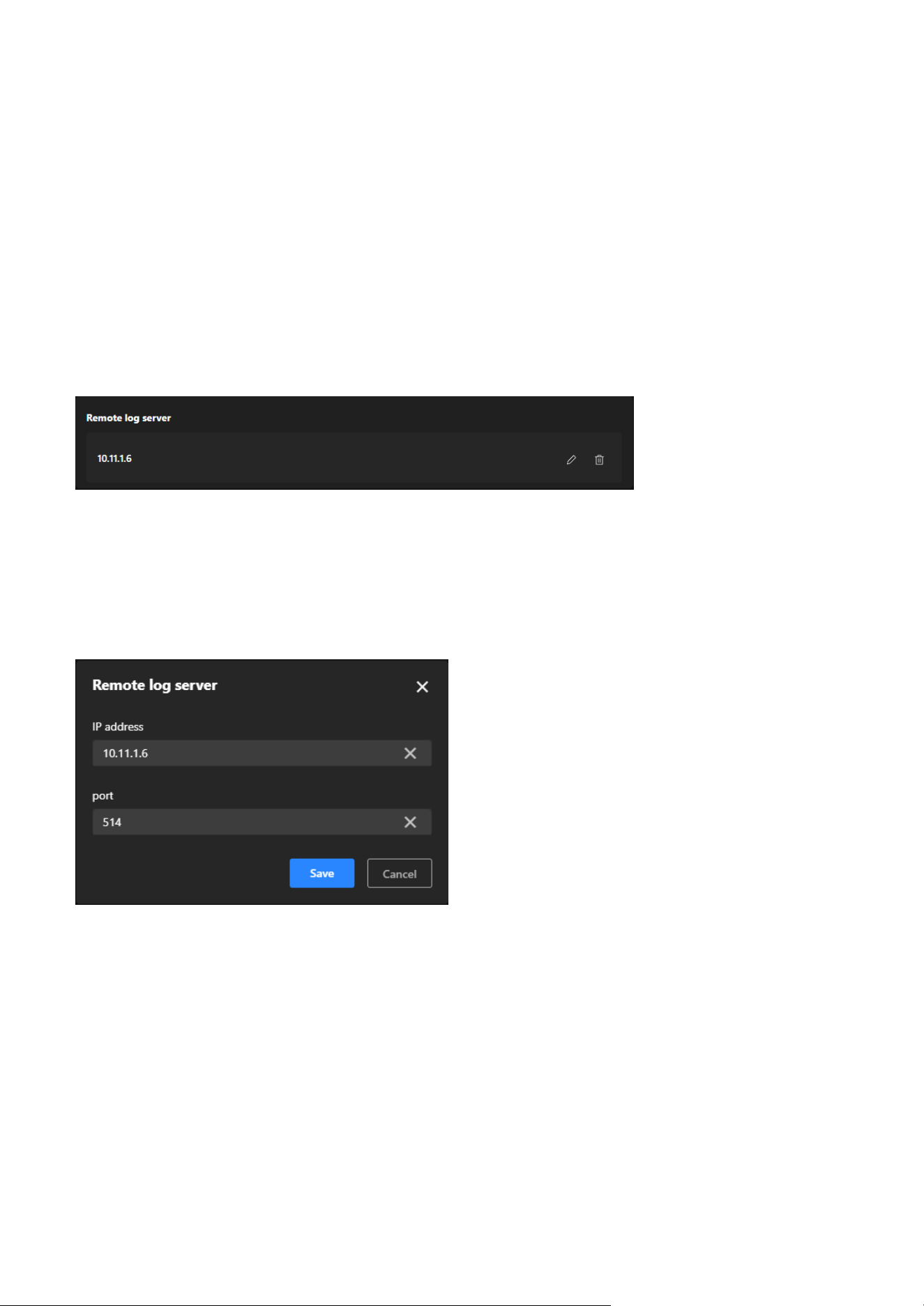
140
9 System
Logs
Remote log server
Logs
Steps to set up the Remote log server:
Step 1. Click “+Add” button.
Step 2. In the IP address text box, enter the IP address of the remote server.
Step 3. In the port text box, enter the port number of the remote server.
Step 4. When completed, click Save to enable the setting.
The Logs provides users with comprehensive tools to monitor and manage system activities, user access,
and configuration changes on the camera. By offering both real-time local log viewing and the ability to
integrate with a remote log server, this tab helps users troubleshoot issues, track security events, and
maintain compliance with operational policies. It is an essential resource for ensuring system reliability,
enhancing security, and supporting centralized log management in multi-device setups.
The Remote log server provides an efficient, secure, and scalable solution for camera log management,
making it particularly valuable in large-scale deployments or environments with stringent data retention
policies.
The Logs provides users with detailed records of system activities, access attempts, configuration
changes, and application performance. It simplifies troubleshooting by helping users identify issues,
enhances security by monitoring access, and ensures transparency in configuration management. This
feature is especially useful for maintaining system stability, tracking unauthorized access, and diagnosing
application or configuration-related problems. The Logs consists of the following categories, each
designed to record specific types of information:
System:
Records key system activities, including device startup, reboot, error messages, and mode switching, to
help determine system stability and identify potential issues.
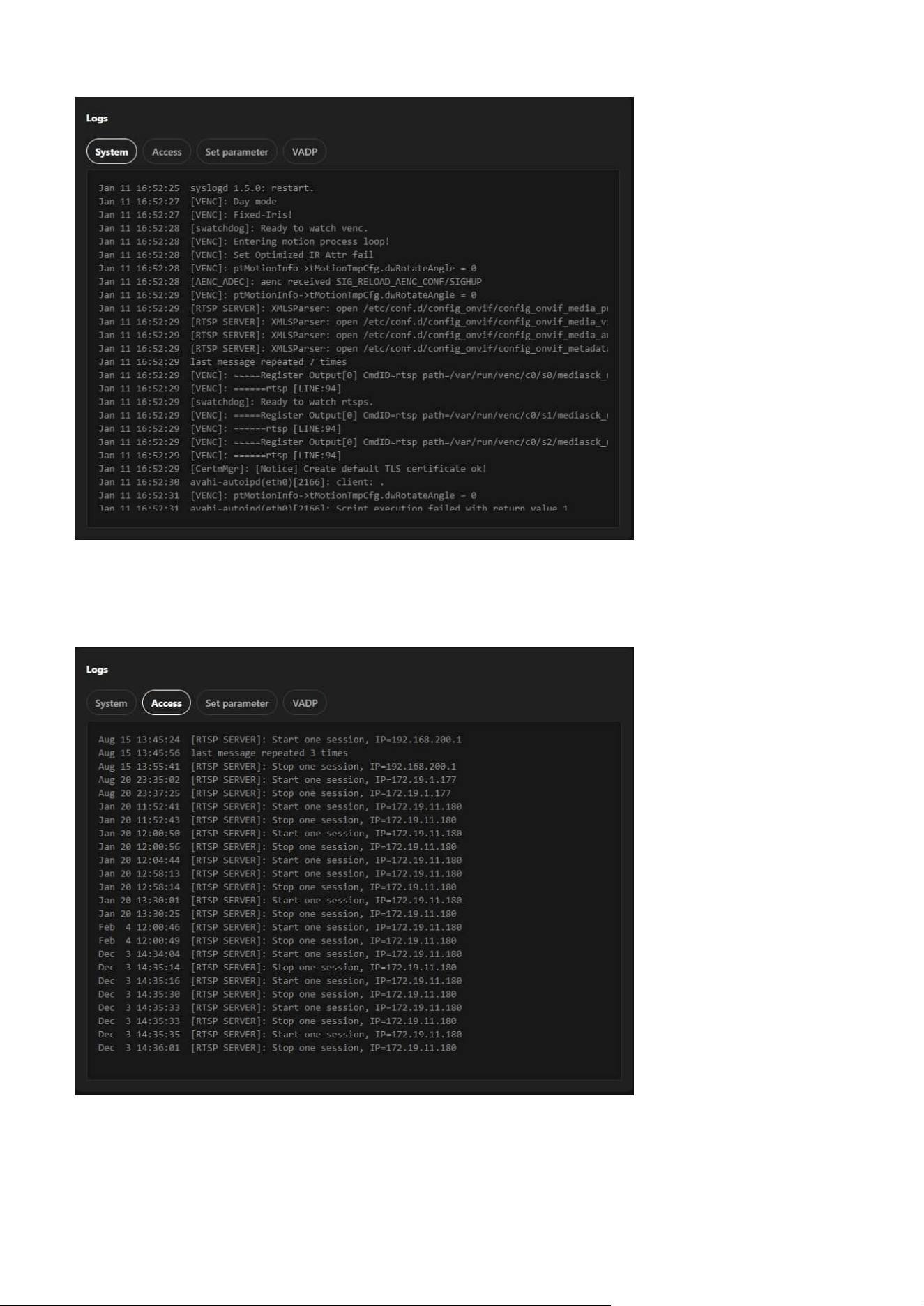
141
9 System
Access:
Logs all access attempts to the camera, including login and logout operations, making it useful for
monitoring unauthorized access attempts and ensuring system security.
Set Parameter:
Tracks all configuration changes made to the system, assisting users in reviewing and managing
adjustments while facilitating troubleshooting of configuration-related issues.
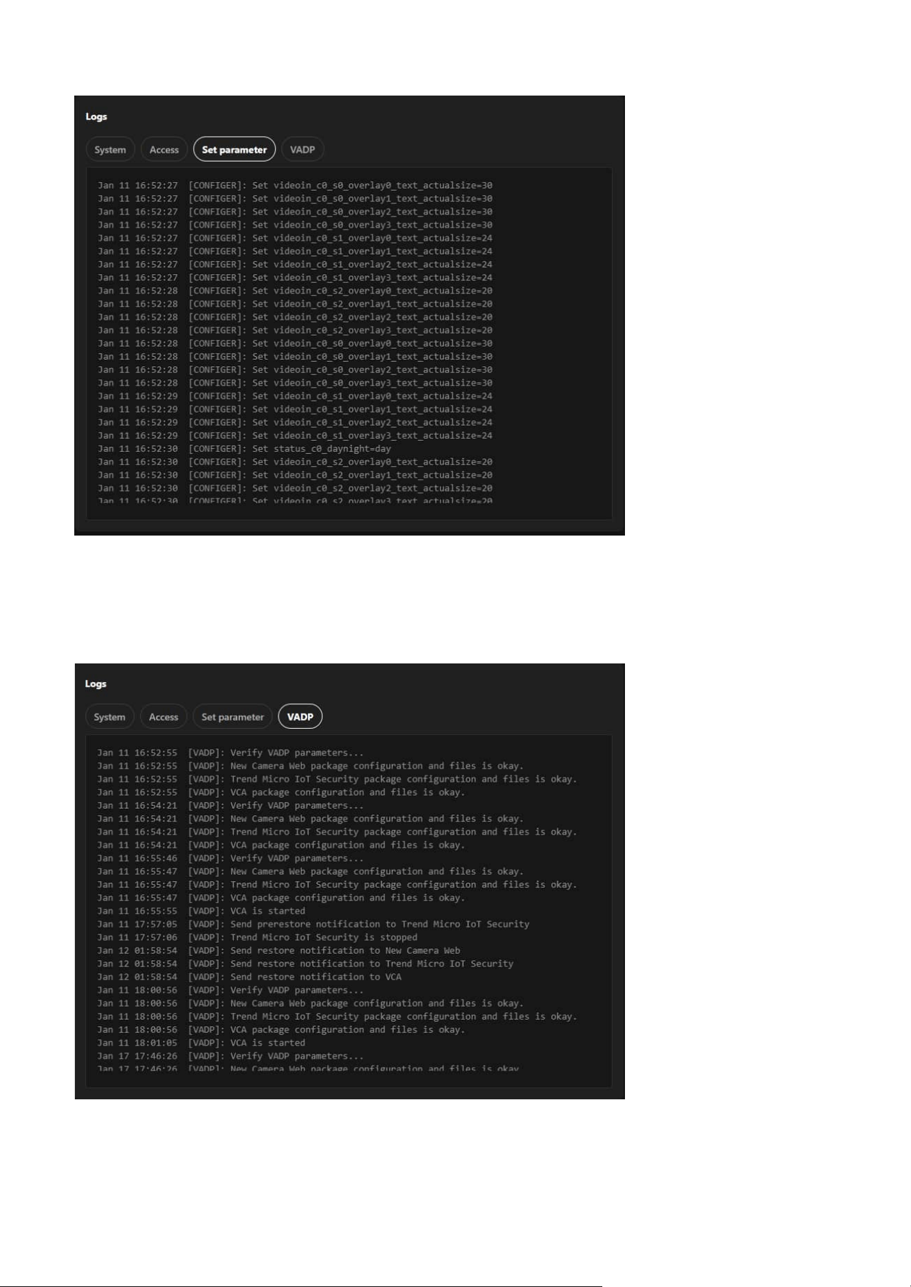
142
9 System
VADP:
Logs related to the VIVOTEK Application Development Platform, documenting the execution of
applications on the camera (if applicable) and helping to diagnose application development and runtime
issues.
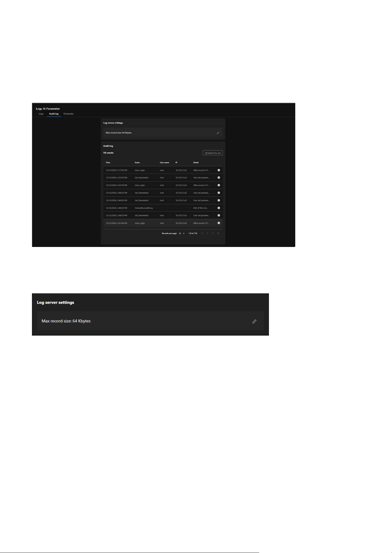
143
9 System
Audit log
Log server settings
Audit log
The Audit log focuses on recording all administrative operations and activities performed on the camera.
Its purpose is to track user behavior, enhance system security, ensure management transparency, and
meet compliance requirements. By logging detailed user actions, it helps administrators analyze issues,
troubleshoot errors, and provide reliable historical data for audits.
Allows users to adjust log storage capacity to ensure sufficient space for recording management activities.
Provides detailed records of each administrative action, including the following fields:
• Time:
The specific time the action occurred.
• Event:
The type of action performed (e.g., "User_Login" for logins, "Set_Parameters" for parameter
adjustments).
• User Name:
The username of the person performing the action (e.g., "root").
• IP:
The IP address of the device initiating the action.
• Detail:
Detailed descriptions of the actions, such as "Allow access HTTP" or "User set parameters."
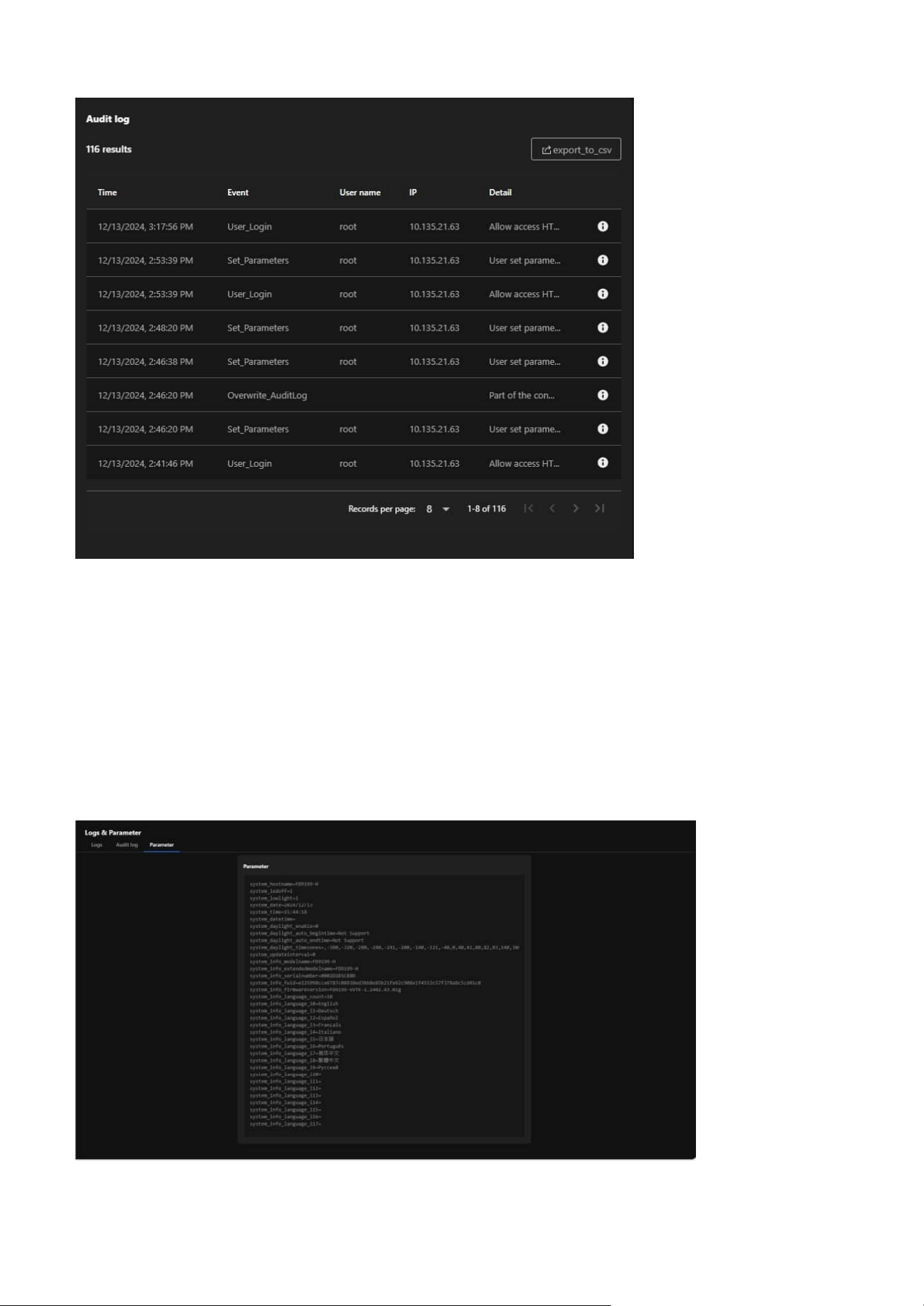
14 4
9 System
Parameter
The Parameter is designed to display the system parameters and configuration details of the camera,
providing administrators with a centralized view of the device's operational status, settings, and technical
information. Its main purpose is to serve as a diagnostic tool, facilitate technical support, and assist in
configuration backup and recovery.
Export Functionality:
The Export to CSV button allows users to export audit logs as CSV files for archiving, sharing, or further
analysis.
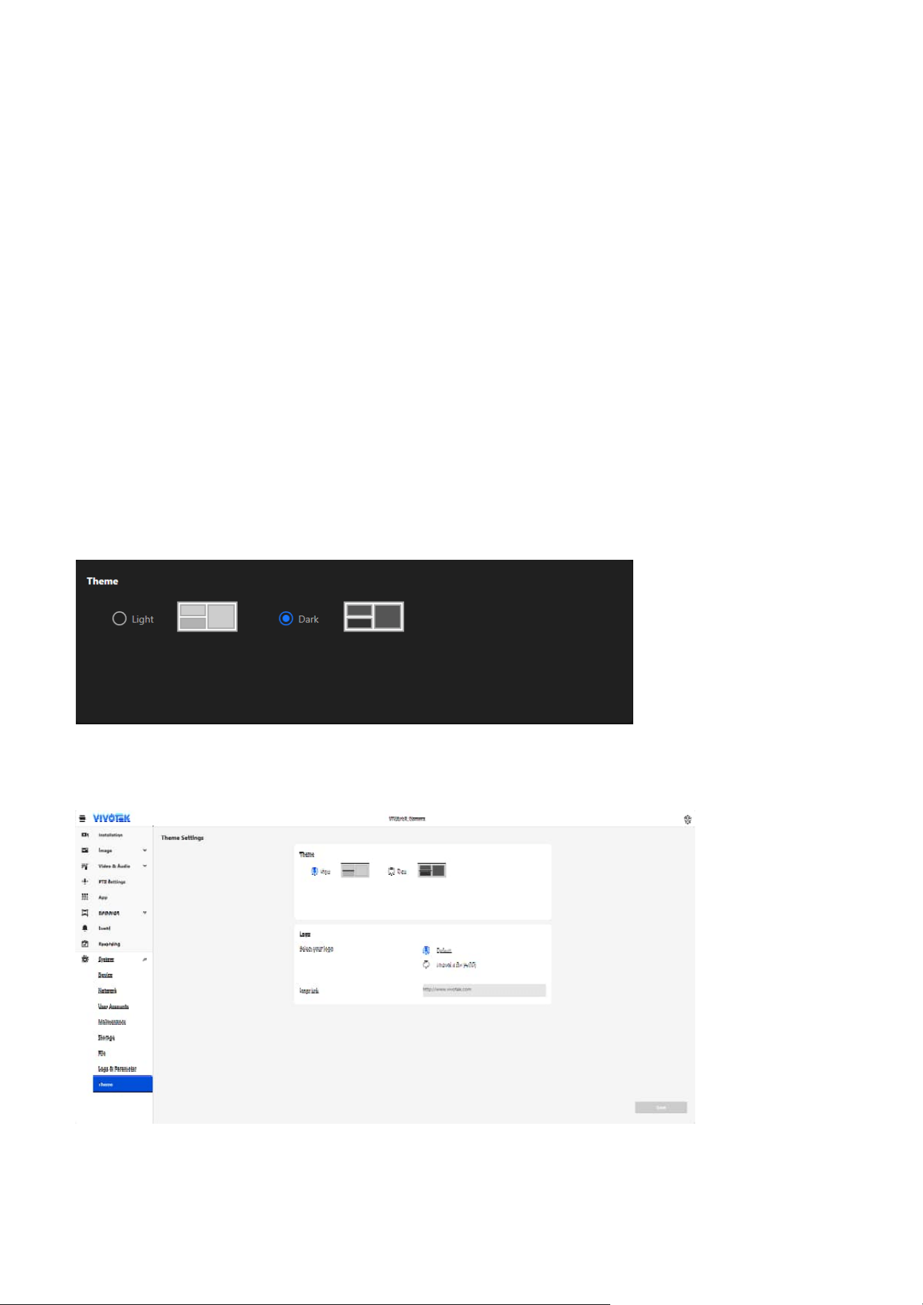
145
9 System
Customizing Interface Appearance and Branding with
Theme Settings
Theme settings
Theme
• Light Mode:
Designed with a light background, ideal for bright environments.
The Theme settings section allows users to personalize the camera’s interface to suit their preferences
and enhance the user experience. By providing options to toggle between light and dark modes, users can
adapt the interface for different lighting conditions. Additionally, the ability to upload a custom logo and
configure a hyperlink enables businesses and projects to showcase their brand identity directly within the
system interface. This feature combines functionality and customization, ensuring both usability and a
professional presentation.
The Theme settings consists of two sections: Theme and Logo, each providing specific customization
options to enhance usability and branding.
Allows users to switch between Light and Dark interface display modes to adapt to different working
environments, enhancing user comfort and reducing eye strain in varying light conditions.
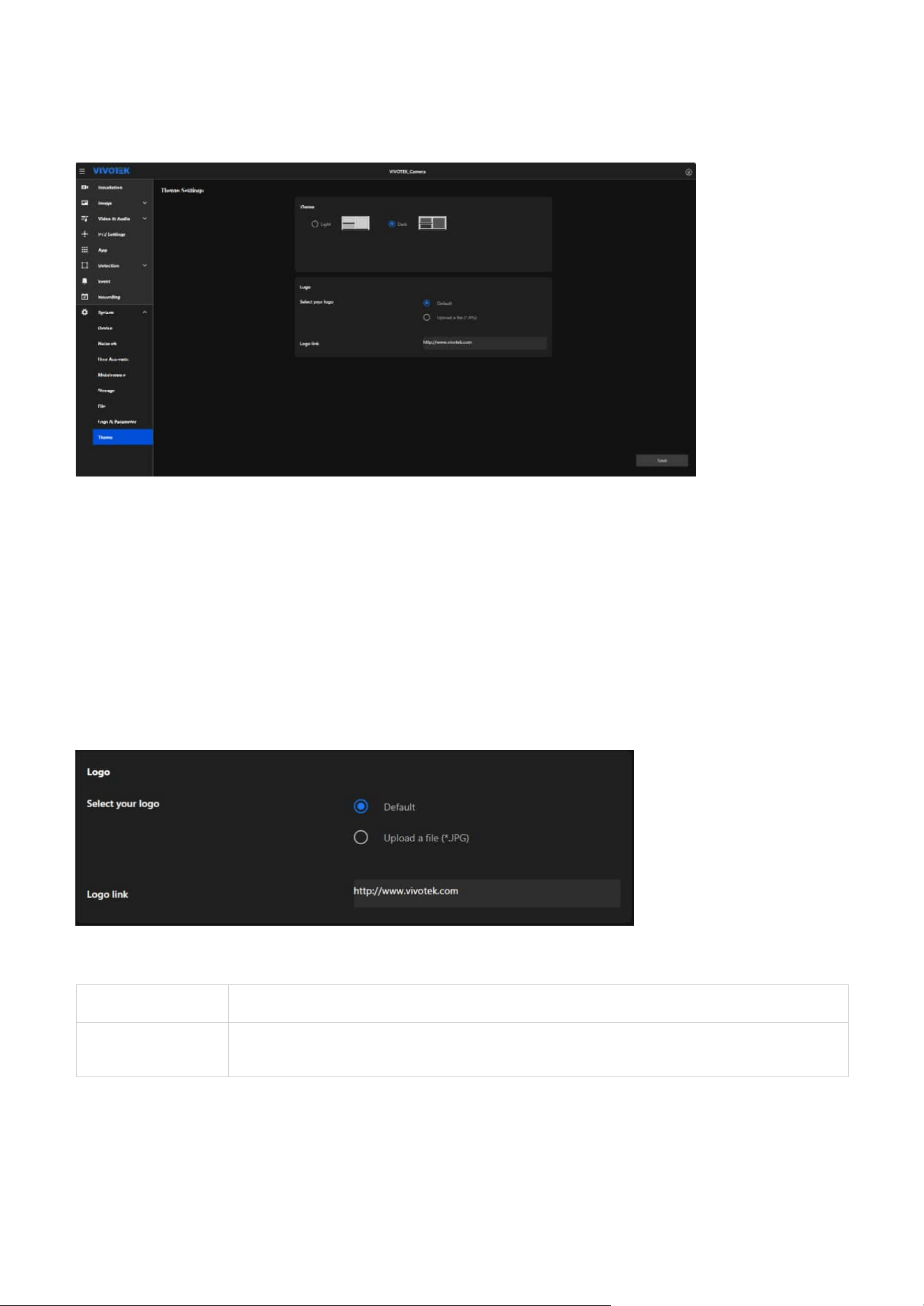
146
9 System
Default Uses the system's built-in default logo.
Upload a file
(*.JPG)
Allows users to upload a custom logo file in JPG format for personalization.
Logo
Enables businesses or users to personalize the interface with their custom logo, enhancing brand
recognition and professionalism, while also providing the option to configure a clickable hyperlink for the
logo that redirects users to a specific webpage, such as a company website or support page.
Select your logo:
How to Operate:
Step 1. Select the desired mode (Light or Dark) by clicking the corresponding option.
Step 2. The interface preview changes dynamically to reflect the selected theme.
Step 3. Click the Save button to apply the changes.
• Dark Mode:
Uses a dark background, reducing glare and improving visibility in low-light conditions.
Logo link:
Enables users to assign a hyperlink to the logo, redirecting to a specific webpage (e.g., company website).

147
9 System
Note:
• Display
The selected or uploaded logo will appear on the title bar of the interface, making it visible to all users,
and clicking it will redirect them to the configured URL.

148
Digital Output (DO) Specifications
Web UI Configuration
Accessing DO Settings
DO Pin Characteristics
Electrical Specifications
The DI/DO (Digital Input/Digital Output) interface in VIVOTEK SD9368/84/67/87-EHL cameras enables
integration with external devices such as relays and alarms for enhanced automation and monitoring
capabilities. The SD9387-EHL uses dry contact configuration for reliable and safe external device control.
Navigate to System > Device > LED & DIDO to configure the Digital Output settings.
The DO pins are dry contacts with three terminal configurations: Common, Normally Closed, and
Normally Open.
• Contact rating (Resistive load): 1A 30VDC
• Contact rating (Resistive load): 0.3A 125VAC
Note
The DO pins provide voltage-free switching only and do not supply power to external devices.
Appendix A:
DI/DO Conguration Guide
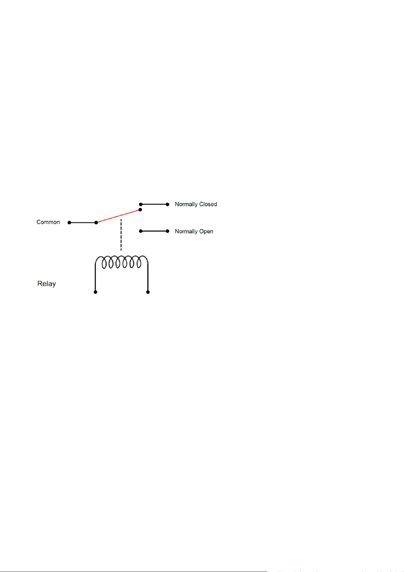
149
Appendix A: DI/DO Configuration Guide
DO Connection Diagram
Implementation Guidelines
Terminal Functions
Basic Wiring Setup
Configuration Options
1. Identify Terminal Configuration: Determine whether your application requires NC or NO operation
2. Connect External Power: Route external device power supply through the relay contacts
3. Establish Common Connection: Use the Common terminal as the primary switching point
4. Configure Web UI: Set the "Normal Status" to match your wiring configuration
• Common: Shared connection point for all switching operations
• Normally Closed (NC): Connected to Common when DO is in non-triggered state
• Normally Open (NO): Connected to Common when DO is triggered
The relay connection utilizes a three-terminal configuration as shown below:
Digital Output Status:
• DO-1 Current Status: Displays the real-time status of the digital output
• DO-1 Normal Status: Configure the default state for the digital output
Normal Status Settings:
• Normal Closed: Circuit is closed (connected) when DO is not triggered
• Normal Open: Circuit is open (disconnected) when DO is not triggered

150
Appendix A: DI/DO Configuration Guide
Alarm System Integration
Common Issues
Access Control Integration
Lighting Control
1. Voltage-Free Operation:
DO contacts provide switching only, never apply external voltage directly to DO pins
2. Load Limitations:
Ensure external loads do not exceed 1A at 30VDC or 0.3A at 125VAC
3. Electrical Isolation:
The dry contact design provides inherent isolation between camera and external circuits
4. Ground Protection:
Maintain proper grounding for all external devices to prevent ground loops
5. Overcurrent Protection:
Install appropriate fuses or circuit breakers in external circuits
• Connect external siren or strobe light
• Use NO configuration for activation upon event trigger
• External 12V power supply required for alarm device
• DO not switching: Verify Web UI configuration matches physical wiring (NC vs NO)
• External device not responding: Check external power supply and load ratings
• Intermittent operation: Ensure contact ratings are not exceeded
• Connect door strike or magnetic lock
• Use NC configuration for fail-safe operation
• External 24V power supply typically required
• Connect external relay module for high-power lighting
• Choose NO or NC based on desired default lighting state
• Independent power supply required for relay coil
Typical Applications
Safety Considerations
Troubleshooting
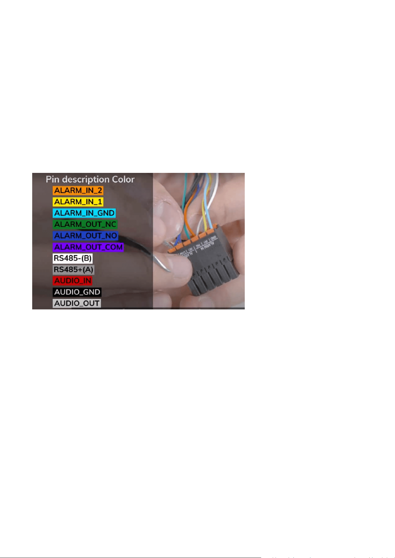
151
Appendix A: DI/DO Configuration Guide
Wiring Information
Verification Steps
Digital Input/Output
Communication Interface
• ALARM_IN_2 - Orange wire
• ALARM_IN_1 - Yellow wire
• ALARM_IN_GND - Light Blue wire
• ALARM_OUT_NC - Green wire (Normally Closed)
• ALARM_OUT_NO - Blue wire (Normally Open)
• ALARM_OUT_COM - Purple wire (Common)
• RS485-(B) - White wire
• RS485+(A) - Dark gray wire
1. Check DO status in System > Device > LED & DIDO
2. Verify external power supply voltage and current capacity
3. Confirm wiring matches selected Normal Status configuration
4. Test with multimeter across DO contacts during trigger events
This configuration ensures safe, reliable control of external devices while maintaining electrical isolation
between the SD9387-EHL camera and external systems.

152
Appendix A: DI/DO Configuration Guide
• Ensure proper color matching when connecting external devices
• Use appropriate wire gauge for current ratings
• Maintain proper cable length to avoid signal degradation
• Secure all connections to prevent intermittent contact
This guide provides a detailed overview of DI/DO configurations, enabling safe, reliable, and flexible
integration with external devices. For further details or troubleshooting, consult the device’s user manual
or contact technical support.
Audio Interface
• AUDIO_IN - Red wire
• AUDIO_GND - Black wire
• AUDIO_OUT - Light gray wire
Important Wiring Notes

DESIGN AND SPECIFICATIONS ARE SUBJECT TO CHANGE WITHOUT NOTICE
Copyright © 2025 VIVOTEK INC. All rights reserved.
www.vivotek.com