
Technical Support and E-Warranty Certificate
www.vevor.com/support
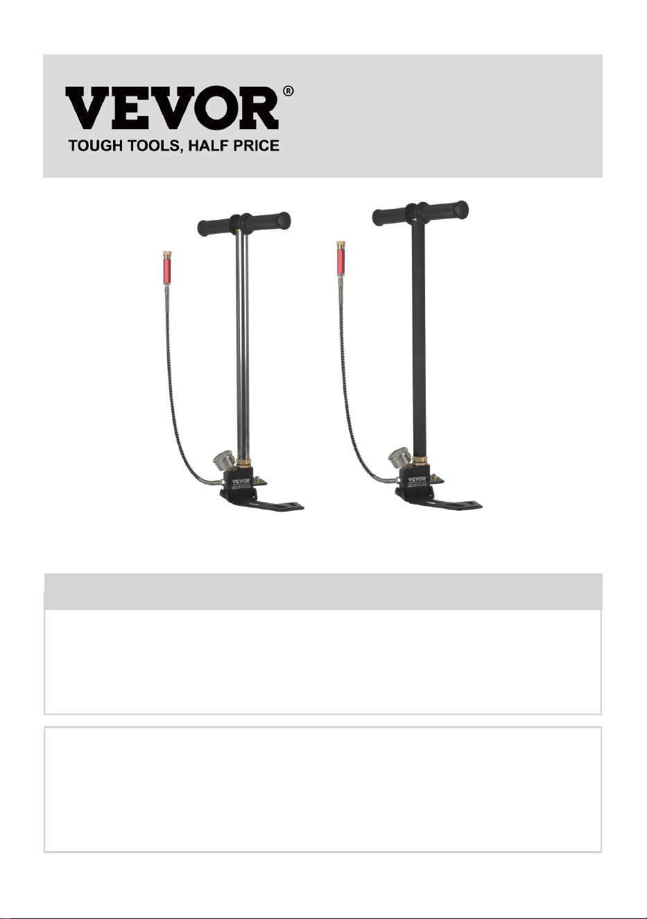
PCP AIR PUMP INSTRUCTIONS
MODEL: DQT-3JB / DQT-3JH
We continue to be committed to provide you tools with competitive price.
"Save Half", "Half Price" or any other similar expressions used by us only represents an
estimate of savings you might benefit from buying certain tools with us compared to the major
top brands and does not necessarily mean to cover all categories of tools offered by us. You
are kindly reminded to verify carefully when you are placing an order with us if you are
actually saving half in comparison with the top major brands.

- 1 -
Have product questions? Need technical support? Please feel free to
contact us:
Technical Support and E-Warranty Certificate
www.vevor.com/support
NEED HELP? CONTACT US!
This is the original instruction, please read all manual instructions
carefully before operating. VEVOR reserves a clear interpretation of our
user manual. The appearance of the product shall be subject to the
product you received. Please forgive us that we won't inform you again if
there are any technology or software updates on our product.
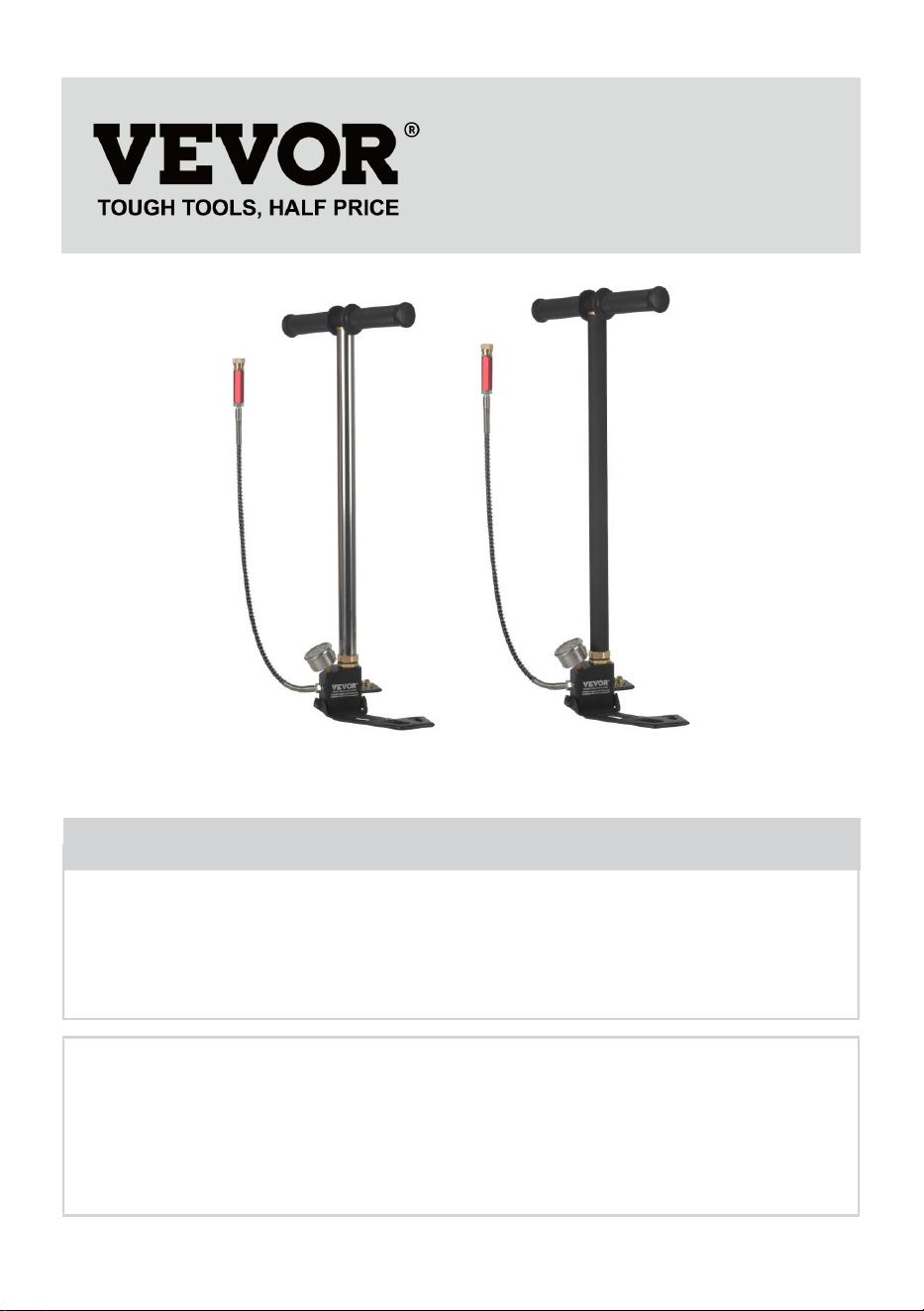
PCP AIR PUMP
MODEL:DQT-3JB
MODEL:DQT-3JH
- 2 -
Warning-To reduce the risk of injury, user must read
instructions manual carefully.
WARNING
1. This manual contains repair methods, please keep it safe for future
review.
2. Do not use this product when it is harmful.
3. It is forbidden to add lubricating oil to new equipment.
4. First loosen the pressure relief valve when the inflation is
completed, and do not pull out the gas pipe connector under
pressure.
5. Do not use pressure exceeding 31mpa/310bar/4500psi.
6. Ensure that the pressurized container is used within the safe
pressure range and within the inspection period, the pressurized
container must be equipped with safety explosion-proof devices.
7. Do not allow children to operate the device and store it in the place
where children cannot touch it.
8. Do not use this product or this manual by people who are not
familiar with it.
9. Do not operate this product on uneven, sloping or slippery ground.
SAVE THIS MANUAL
Model
Compression
principle
MWP
Base
Oil and water filtration
DQT-3JB
Level 3
compression
4500 PSI
Folding
base
Oil and water filter
DQT-3JH
- 3 -
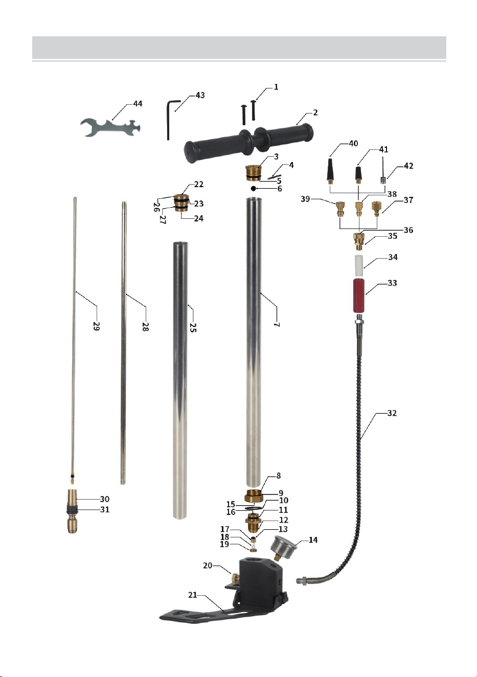
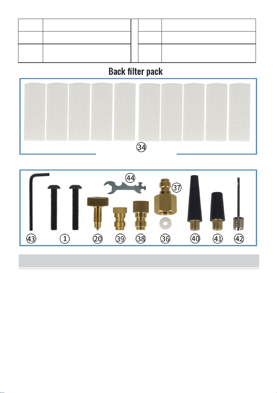
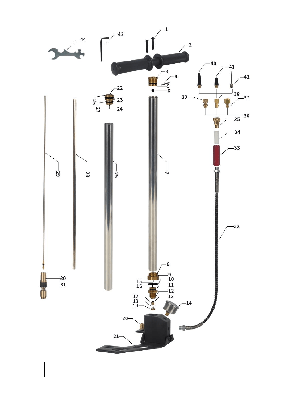
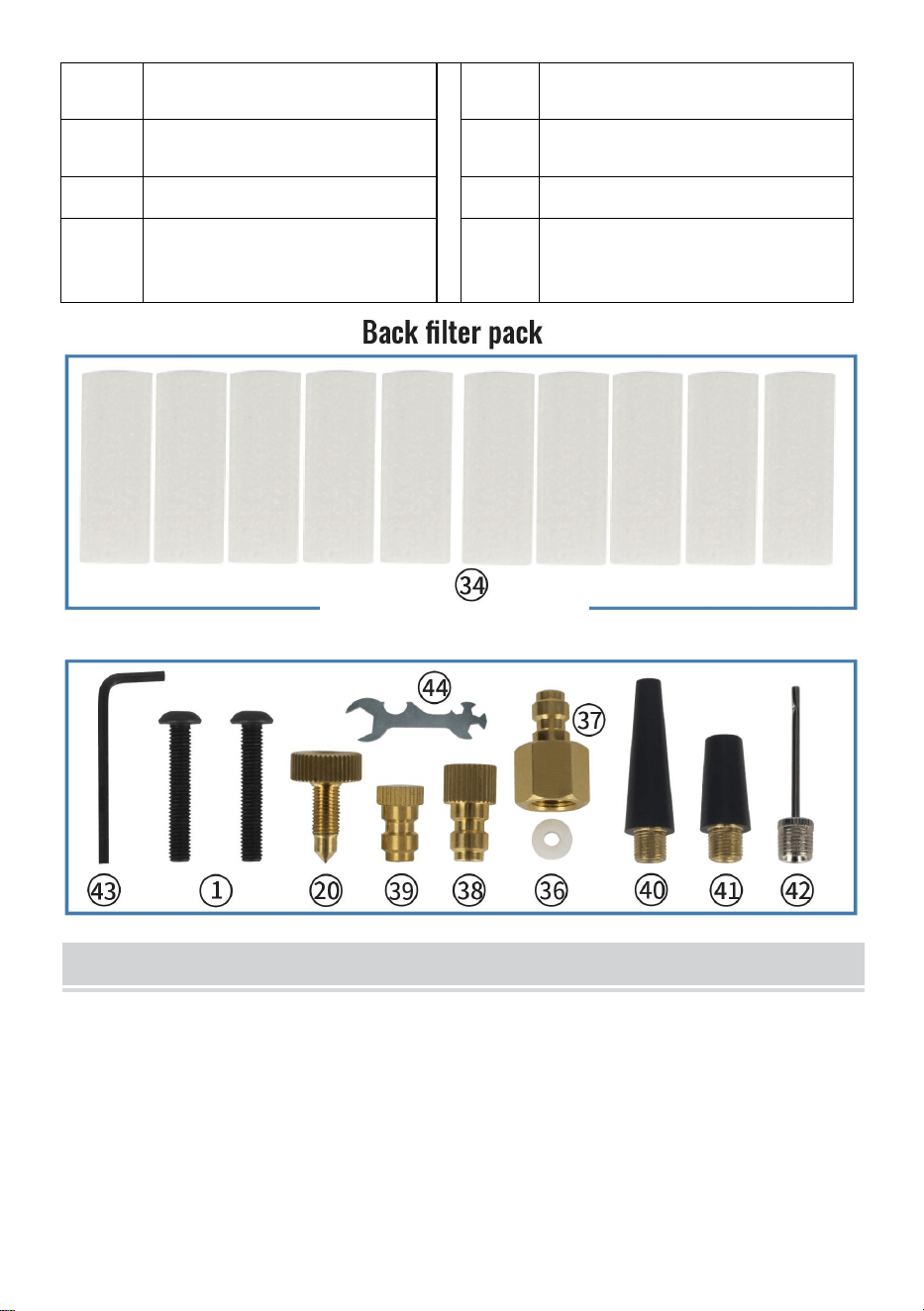
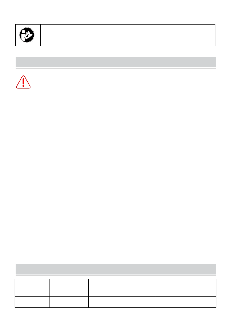
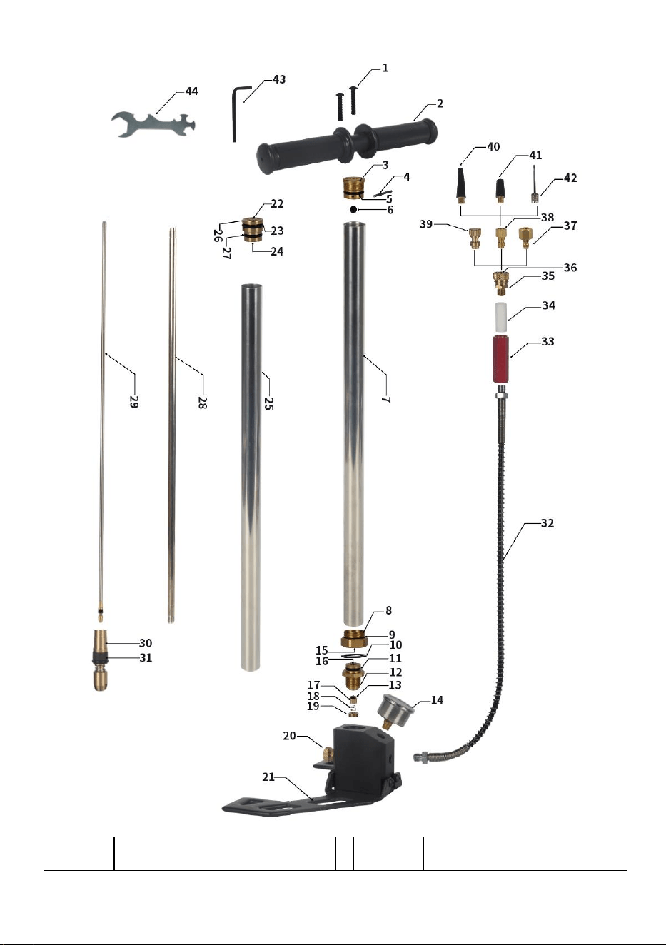
PART NAME

- 4 -
NO.
Name of parts
NO.
Name of parts
1
Handle screw
23
Two stage piston seal ring
2
Handle
24
Secondary piston lower
inner O-ring
3
Handle mounting body
25
Secondary pump body
tube
4
Three lever fixing pin
26
Two-stage piston
5
Intake valve body seal
ring
27
Two stage piston bottom
outer seal ring
6
Air intake seals the ball
28
Three stage pump body
pipe
7
Primary pump body pipe
29
High pressure solid rod
8
First stage piston
30
Four-stage piston head
9
Primary piston outer
O-ring
31
Four stage piston ring
10
Cushion
32
Exit pipe
11
O-ring in secondary tube
33
Oil-water filter
12
High pressure one-way
valve body
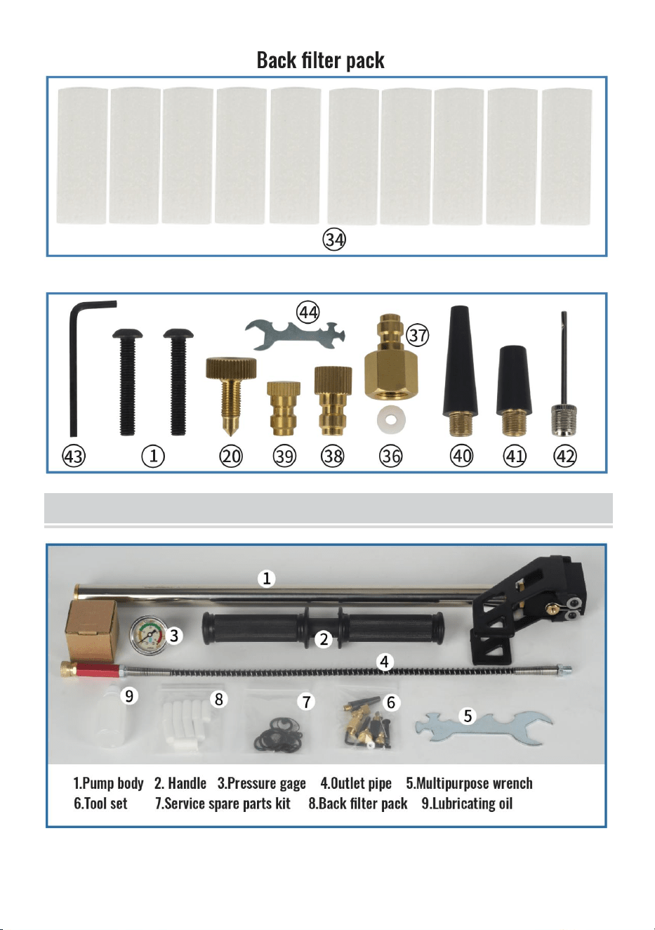
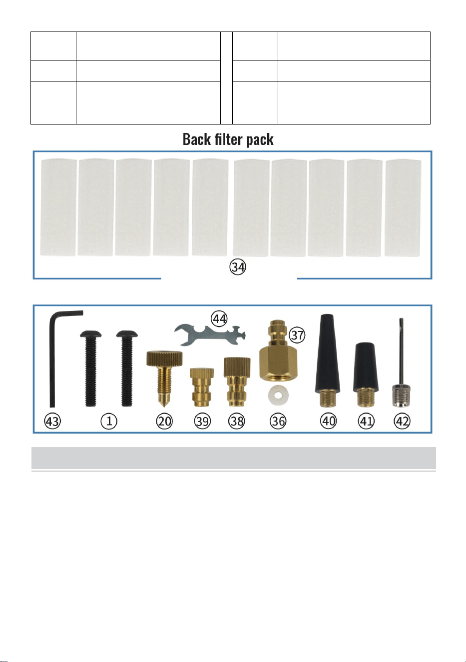
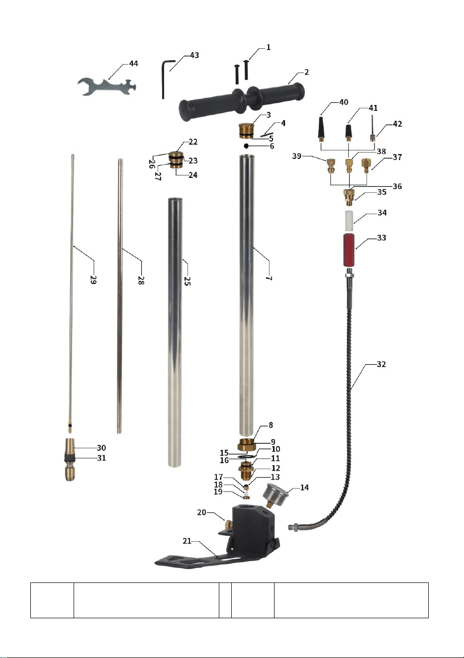
34
Oil water filter element
13
Check valve seal ring
35
Adapter quick socket
14
Pressure gage
36
Quick seat seal ring
15
First piston inner O-ring
37
1/8 BSP internal screw
inflatable adapter
16
Triple tube outer O-ring
38
American tire valve
adapter
17
High pressure check
valve
39
Test the plug quickly
18
Check valve spring
40
Balloon nozzle
19
Check valve limit screw
41
Float inflator nozzle
20
Pressure relief screw
42
Balloon needle for balls
21
Folding base
43
Allen key L
22
Secondary piston upper
inner O-ring
44
Multipurpose wrench
- 5 -
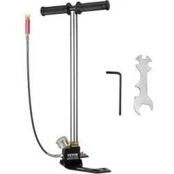
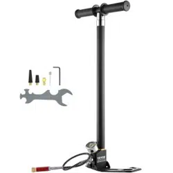
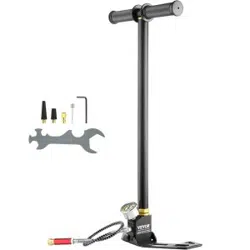
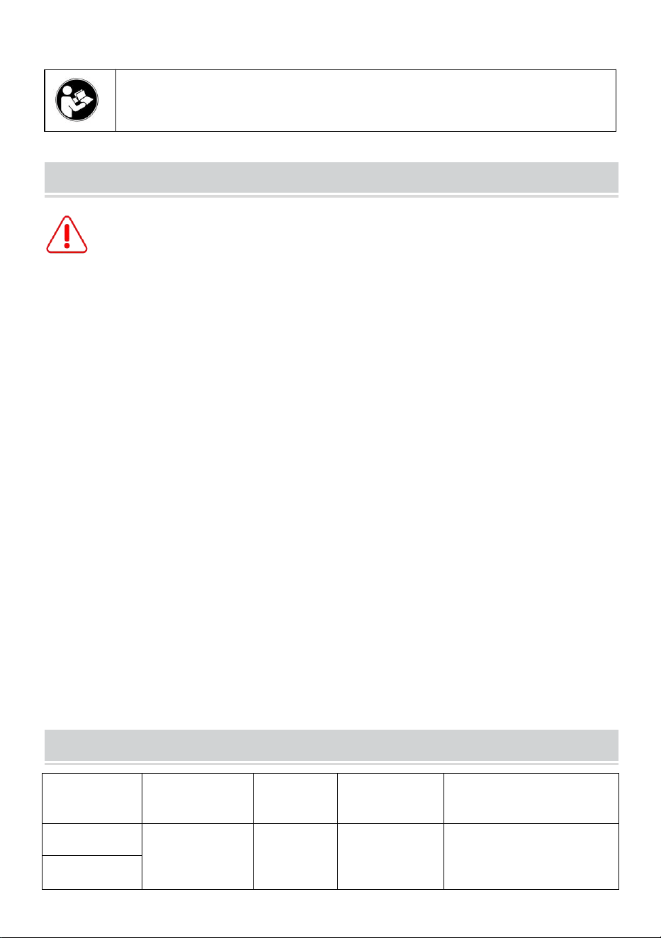
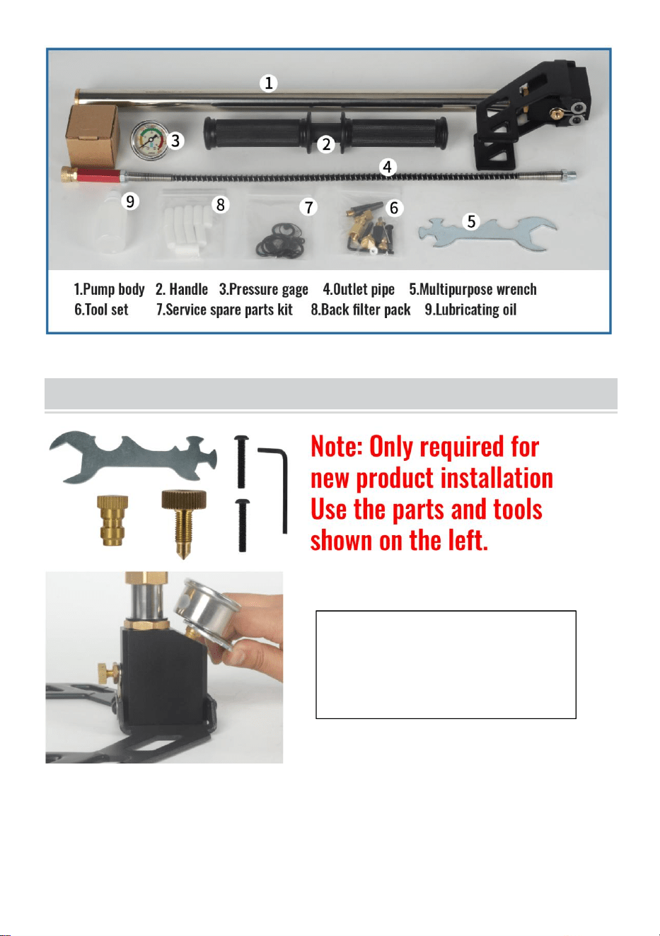
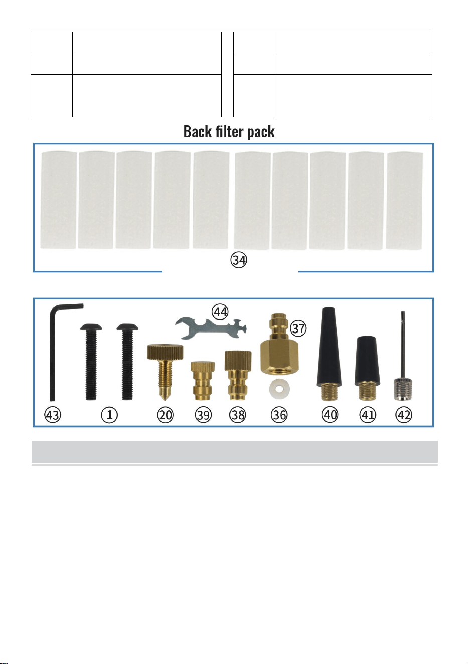
PACKING LIST
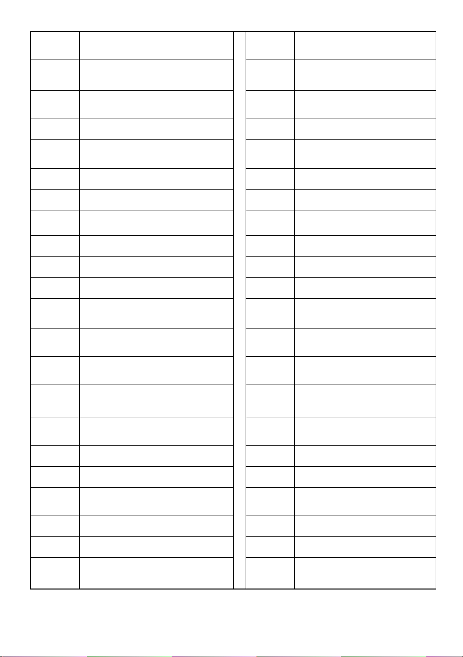
Tool set

- 6 -
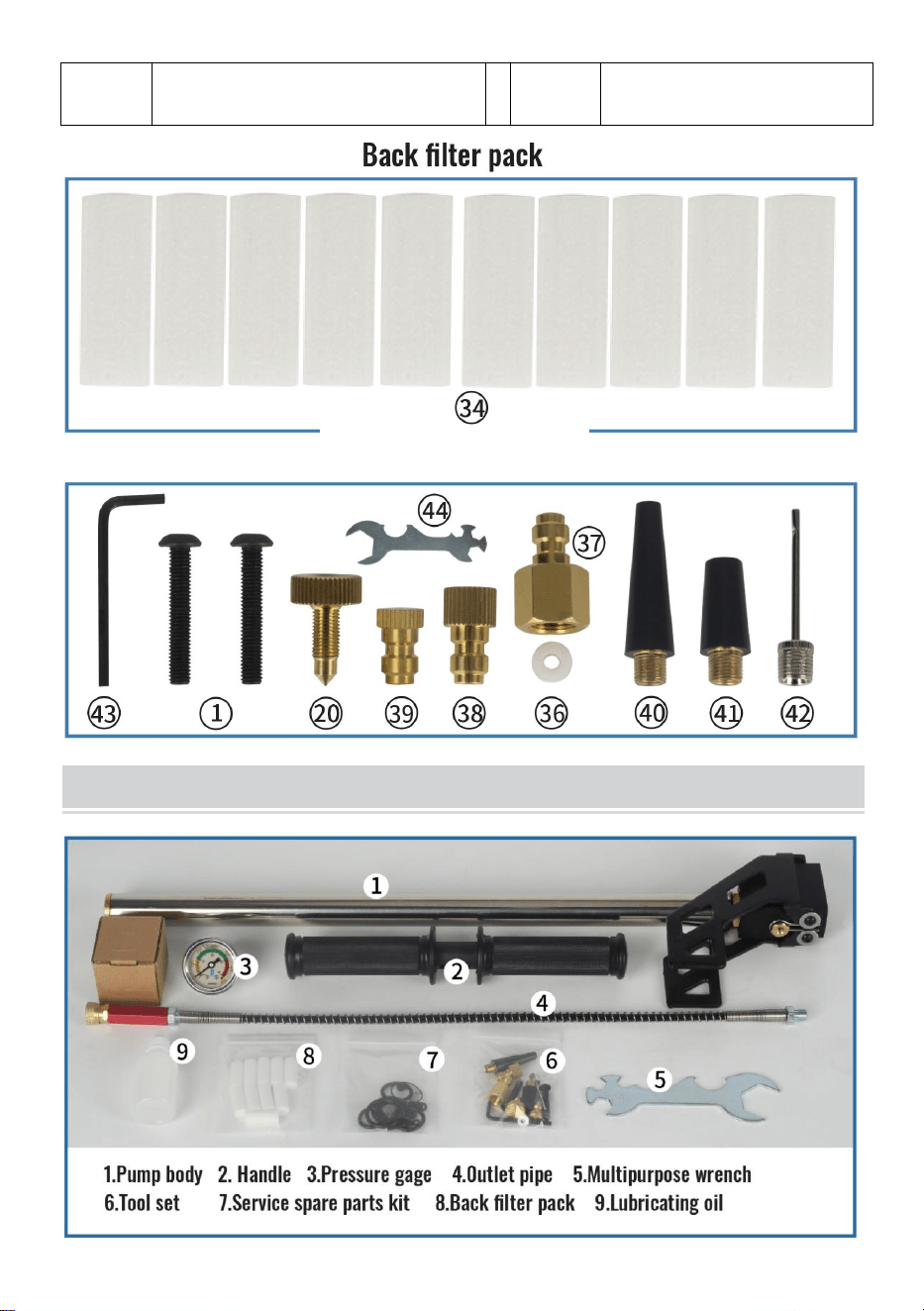
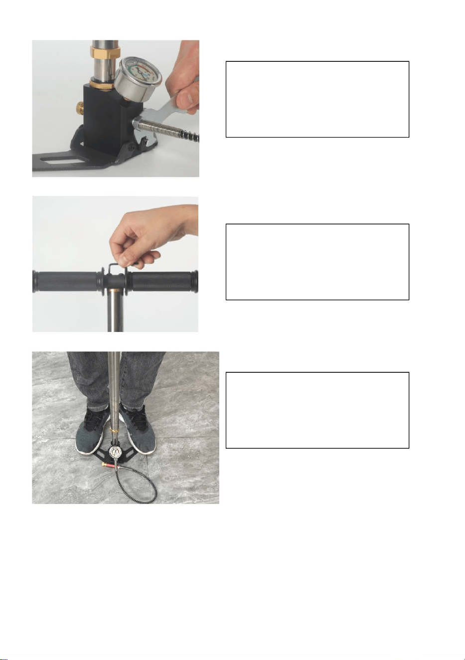
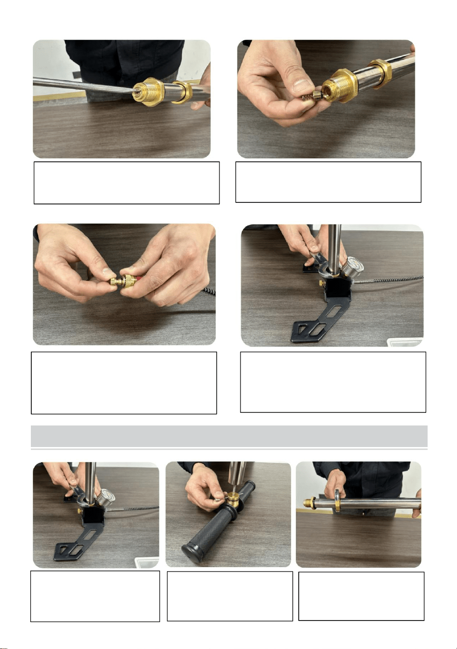
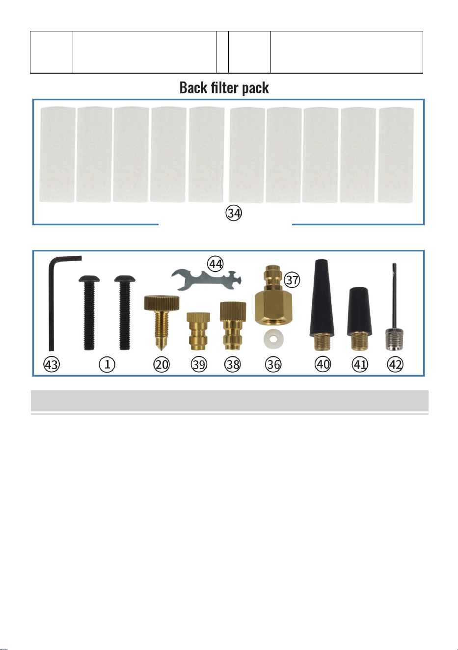
INSTALLATION INSTRUCTIONS
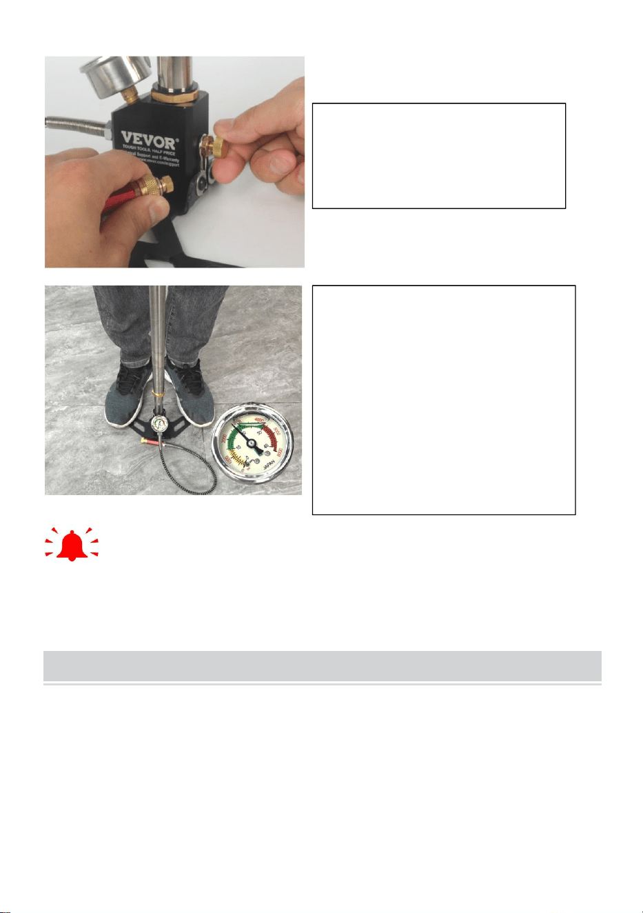
1. Install the pressure gauge
and tighten it using a
multi-function wrench.
2. Install the air exhaust
pipe and tighten it using a
multifunctional wrench.
3. Install the handle and
tighten the screws with an
Allen wrench.
- 7 -
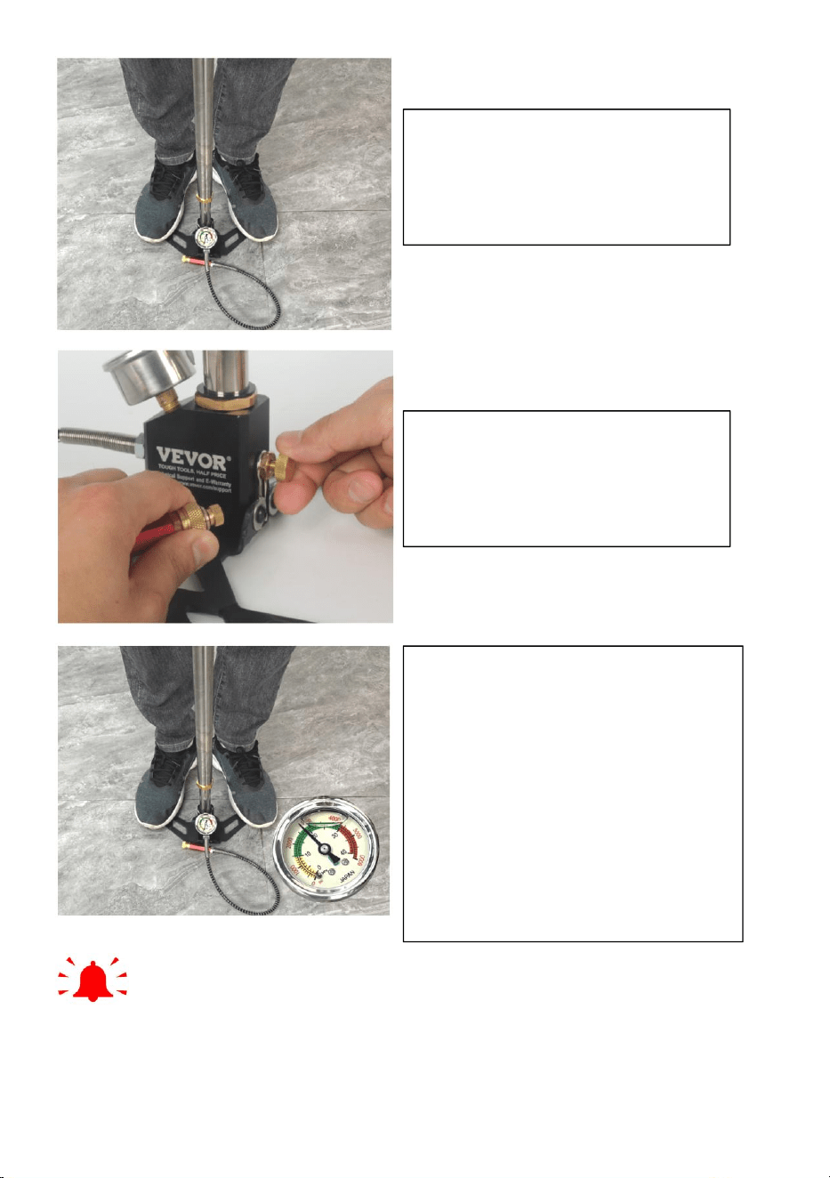
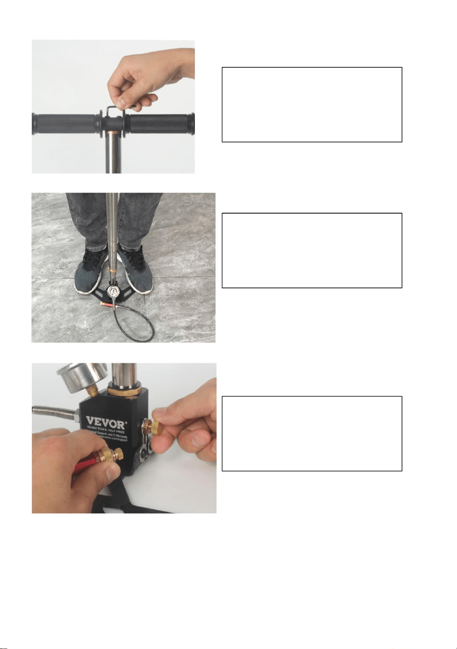
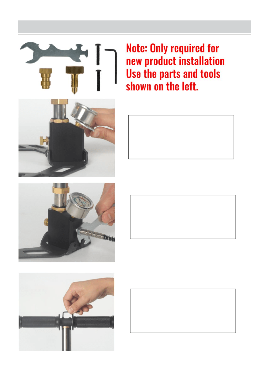
Tip: Plug test pressure should not exceed 3500psi. The very limited
space pressure change can cause the oil to burn and damage the product
seal.
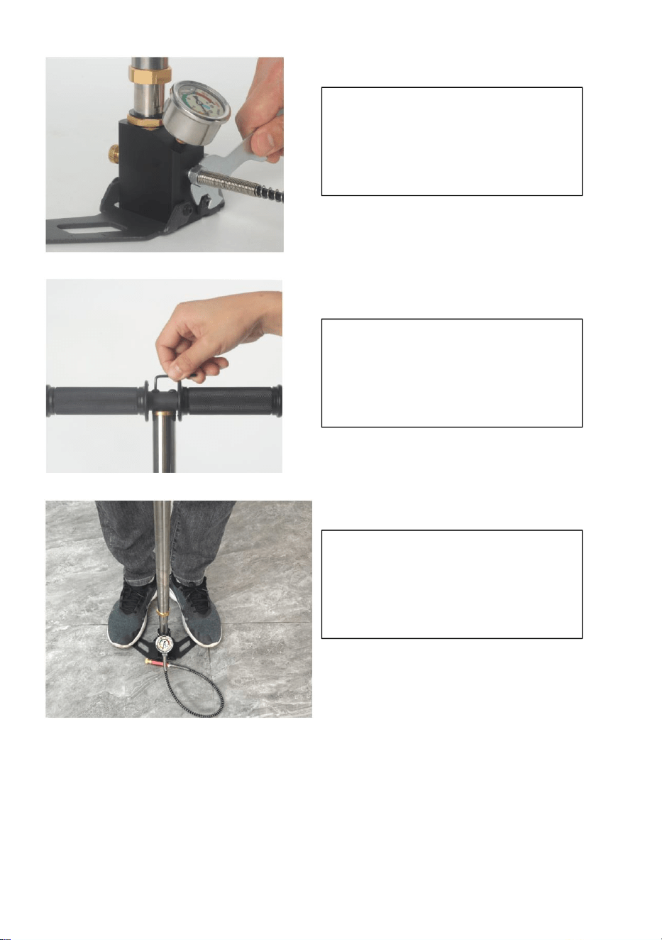
4. Pull the pump up and
down for 100 rounds.
5. Install the pressure test
plug and tighten the
pressure relief screws.
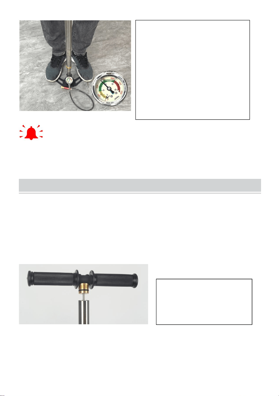
6. Pull the pump up and down
to test whether the product
works normally.
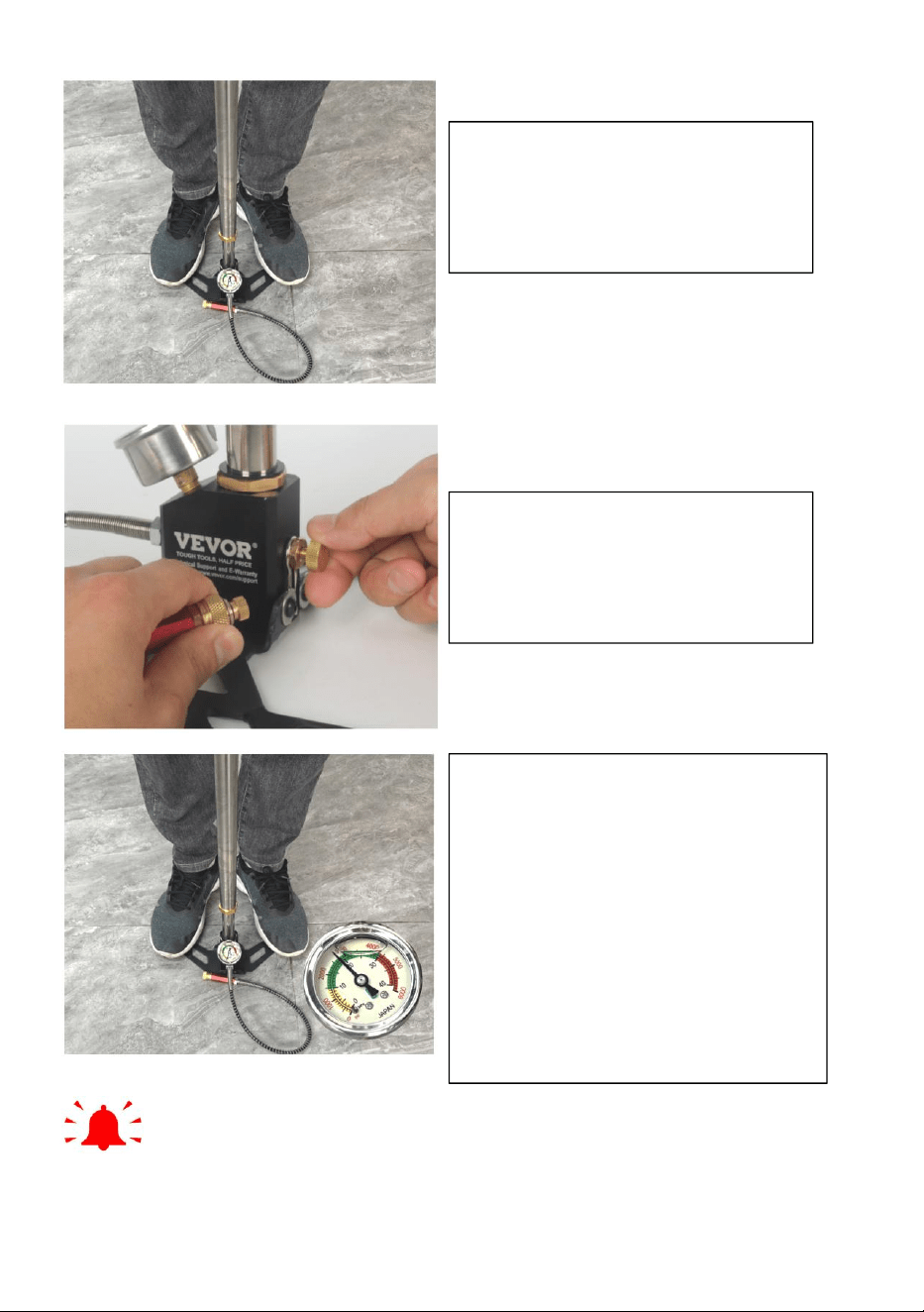
Note: After filling, the
pressure relief valve must be
loosened to remove the
internal pressure before
opening the gas pipe
connector.
- 8 -
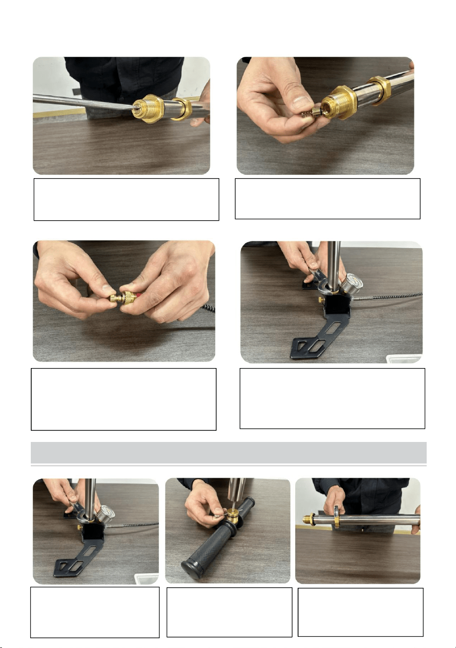
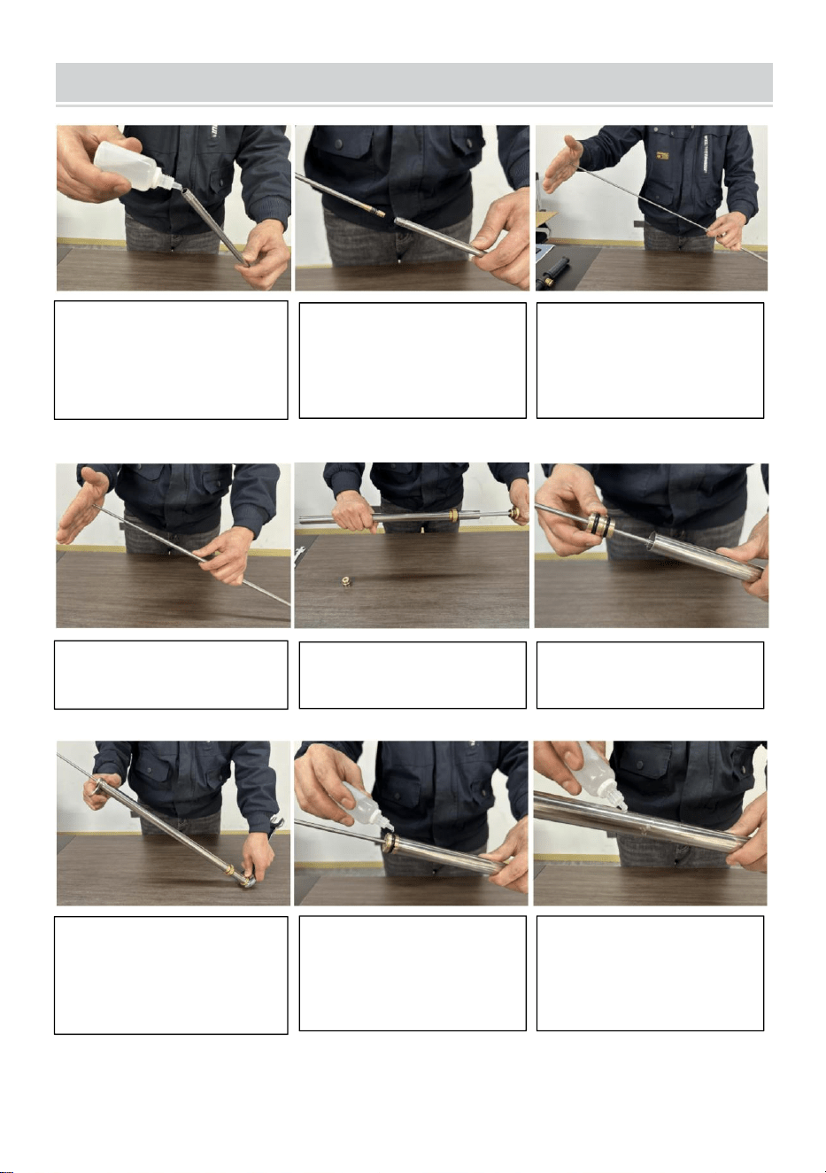
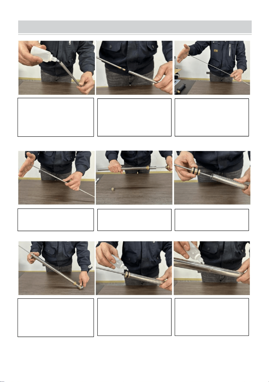
USE AND MAINTENANCE
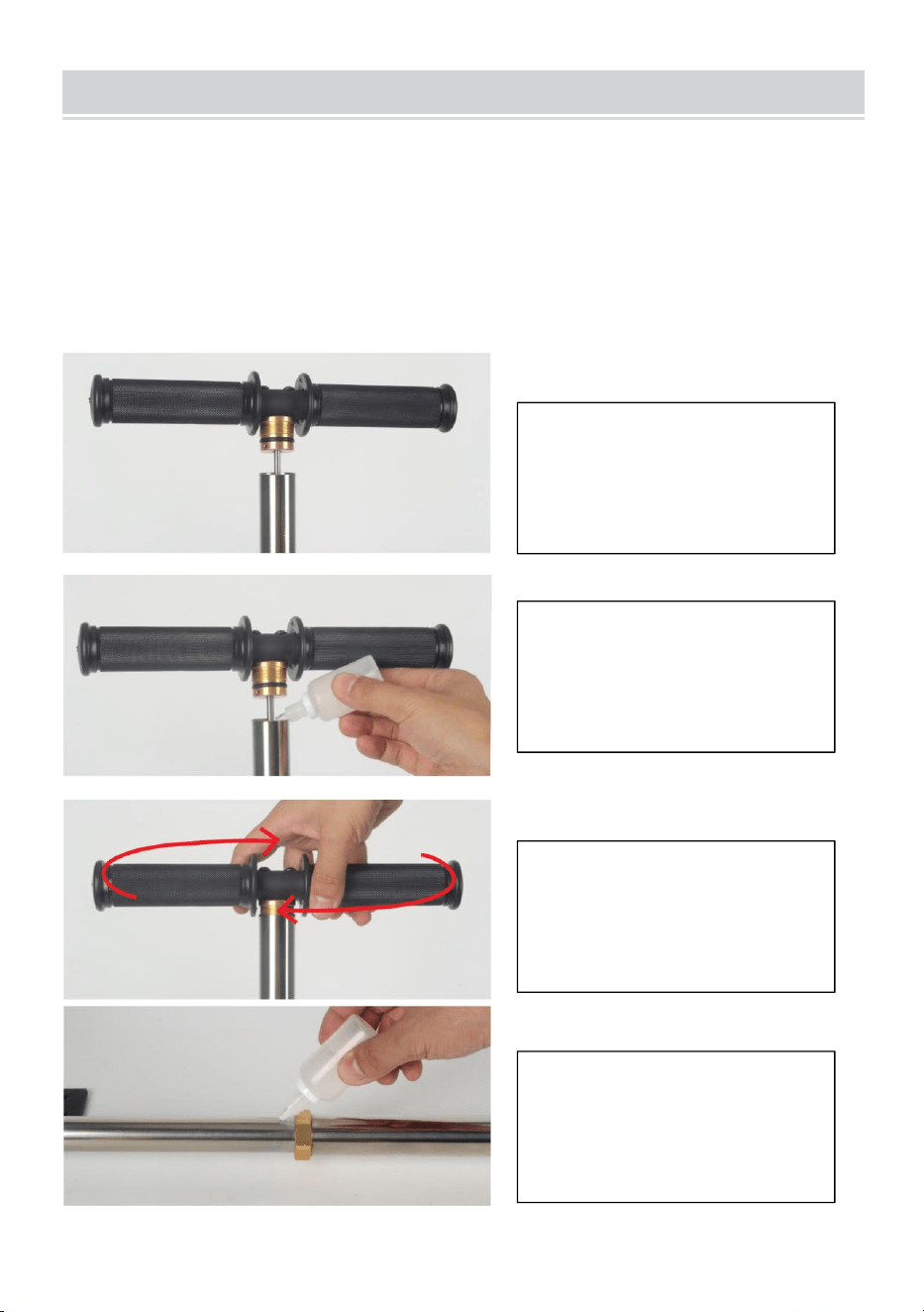
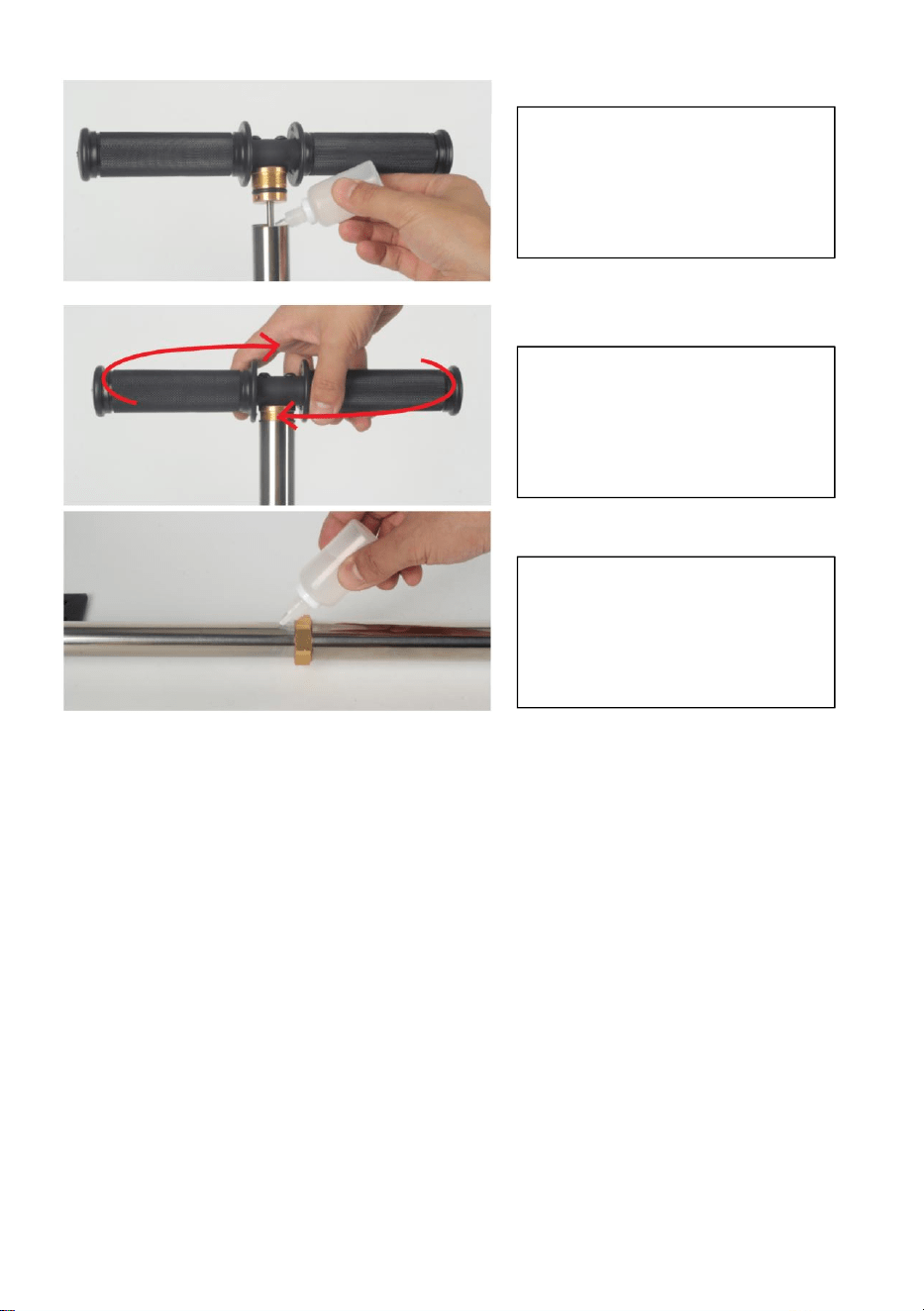
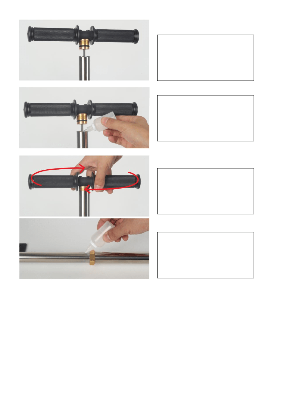
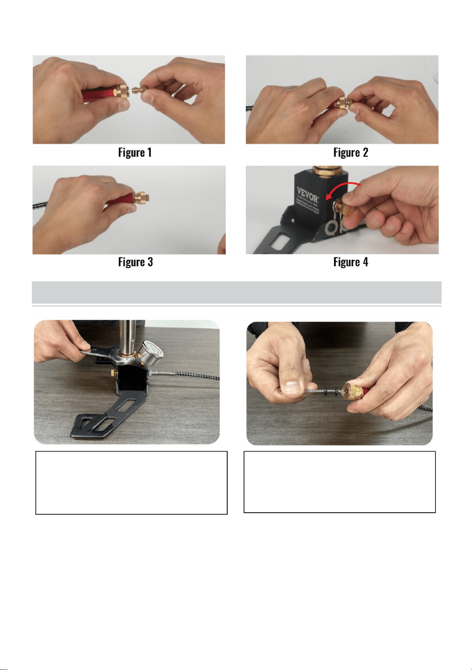
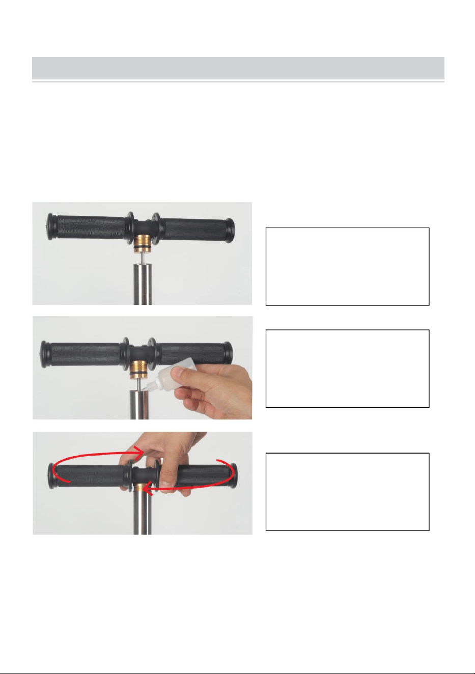
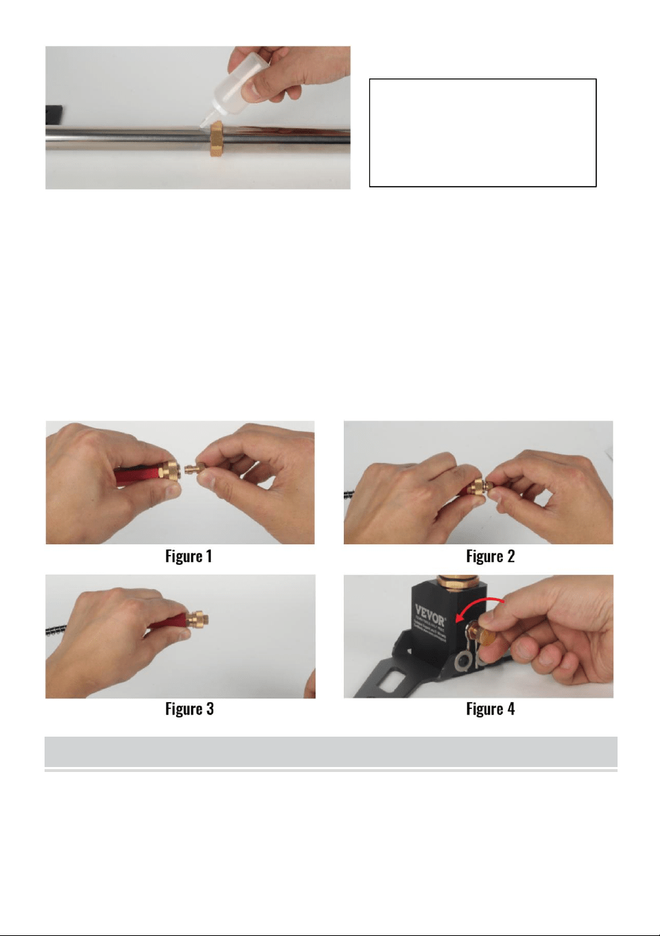
1. Lube job
The new pump does not require refueling. Fill up once every 1500
times or so, there are two positions that need to be filled, and add
three drops of oil to each position (as shown below). After filling up,
stretch the pump about 50 times. When not in use, drain excess
water.
1. Hold the primary
tube and untwist the
handle.
2. Add 3 drops of oil as
shown in Fig.
3. Tighten the handle as
shown.
4.After pulling the
handle up, add 3 drops
of oil as shown.
- 9 -
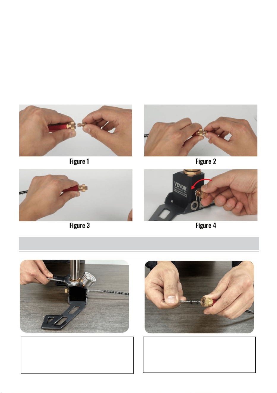
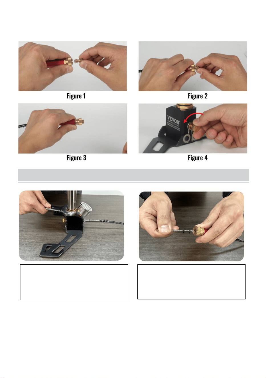
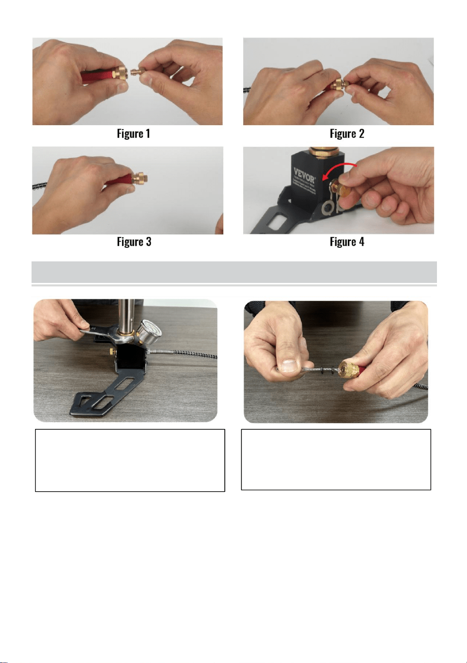
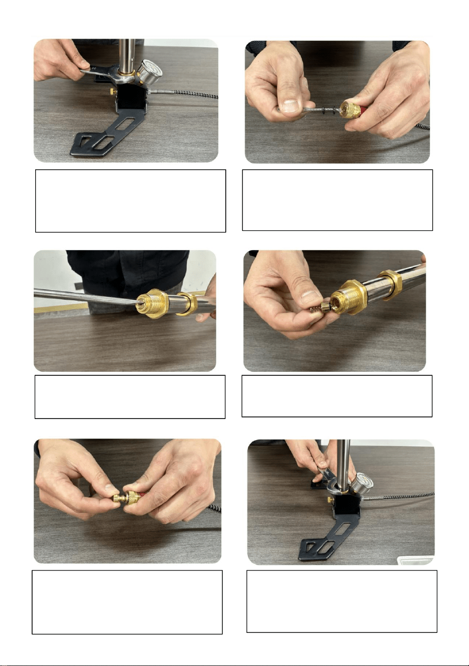
2. Adapter socket installation metho
The adapter socket should be properly installed, otherwise it is prone to
blockage problems (as shown in Figure 1.2.3 below).
3. Decompression
After using the pump, be sure to relieve the pressure first (as shown in
Figure 4 below), and then remove the connector. Usually do not use the
pump, please try to keep no pressure, the hose can not knot, not excessive
bending, do not bump the pressure gauge.
TROUBLESHOOTING
Check whether the primary piston
is loose and the seal ring is
damaged.
Check whether the O-ring of the
adapter socket is 2, which must
be used to seal properly.
- 10 -
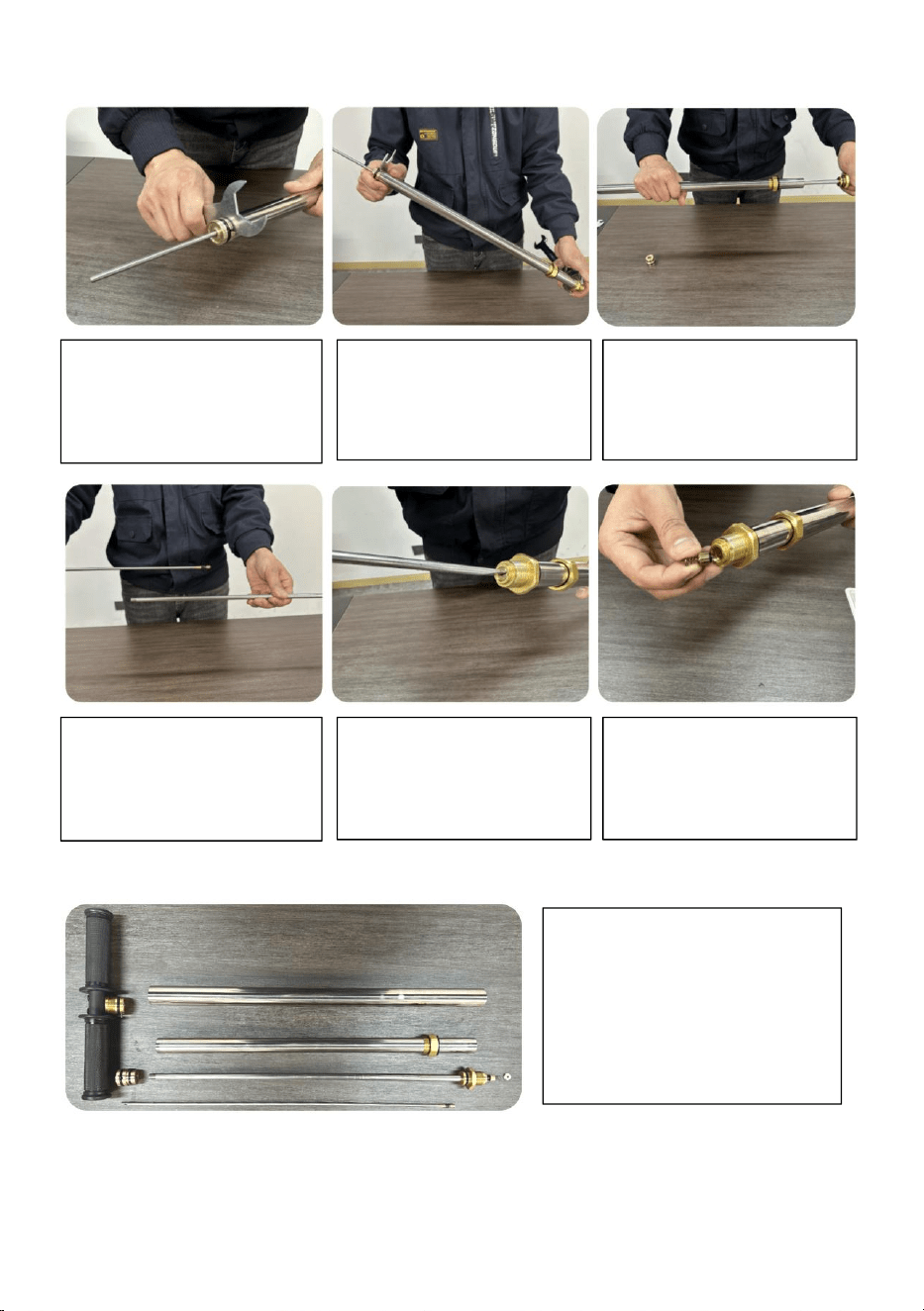
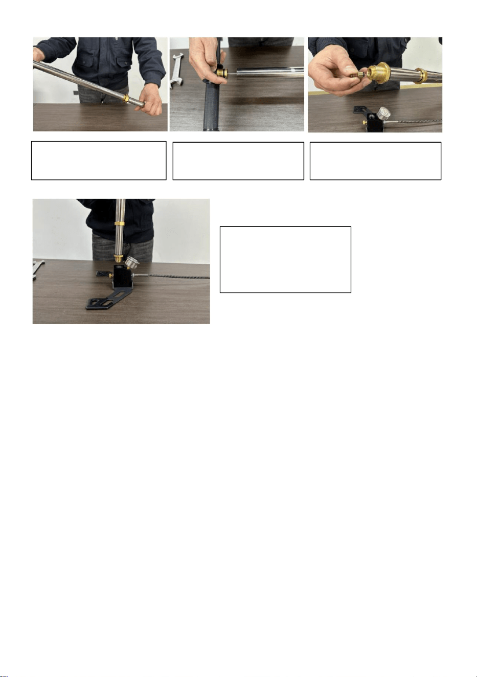
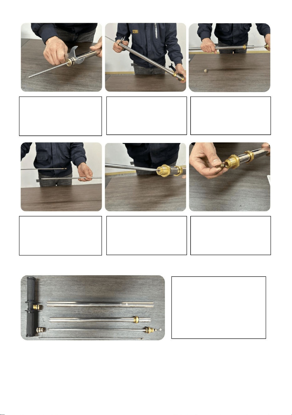
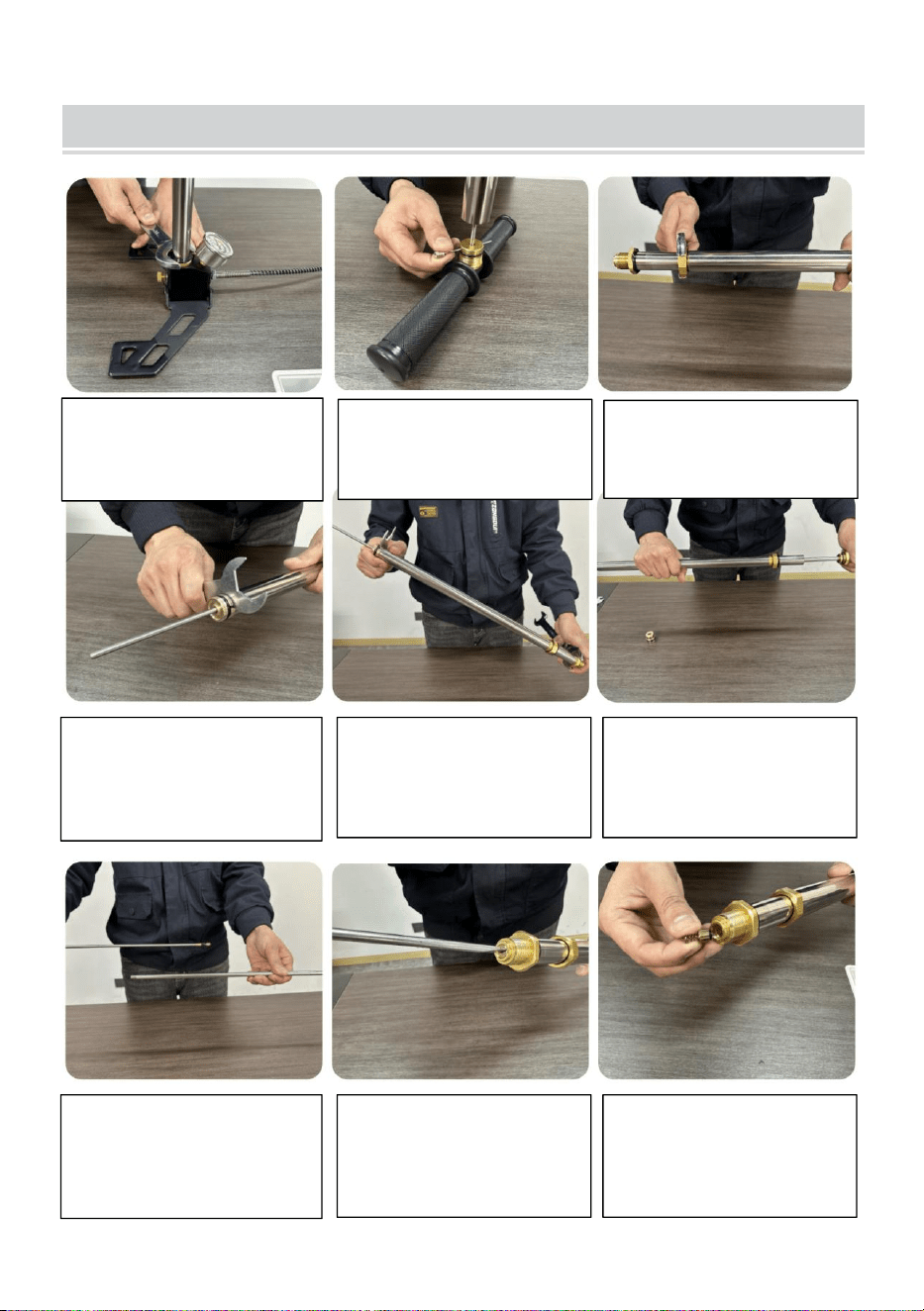
DISASSEMBLY PROCEDURE DIAGRAM
Check valve clean and check
O-ring for damage.
Check valve clean and check
O-ring for damage.
Plug quickly test whether the
product is working properly.
1.Release the wrench
and remove the pump
body.
2.Remove the handle
fixing pin.
3.Loose the primary
piston and remove
the primary tube.
Check whether the primary
piston is loose and the seal
ring is damaged.
- 11 -
4.Stuck the secondary
piston with a
multifunctional
wrench.
5.Check valve body
fixed with a wrench,
remove the two stage
piston.
6.Remove the
secondary.
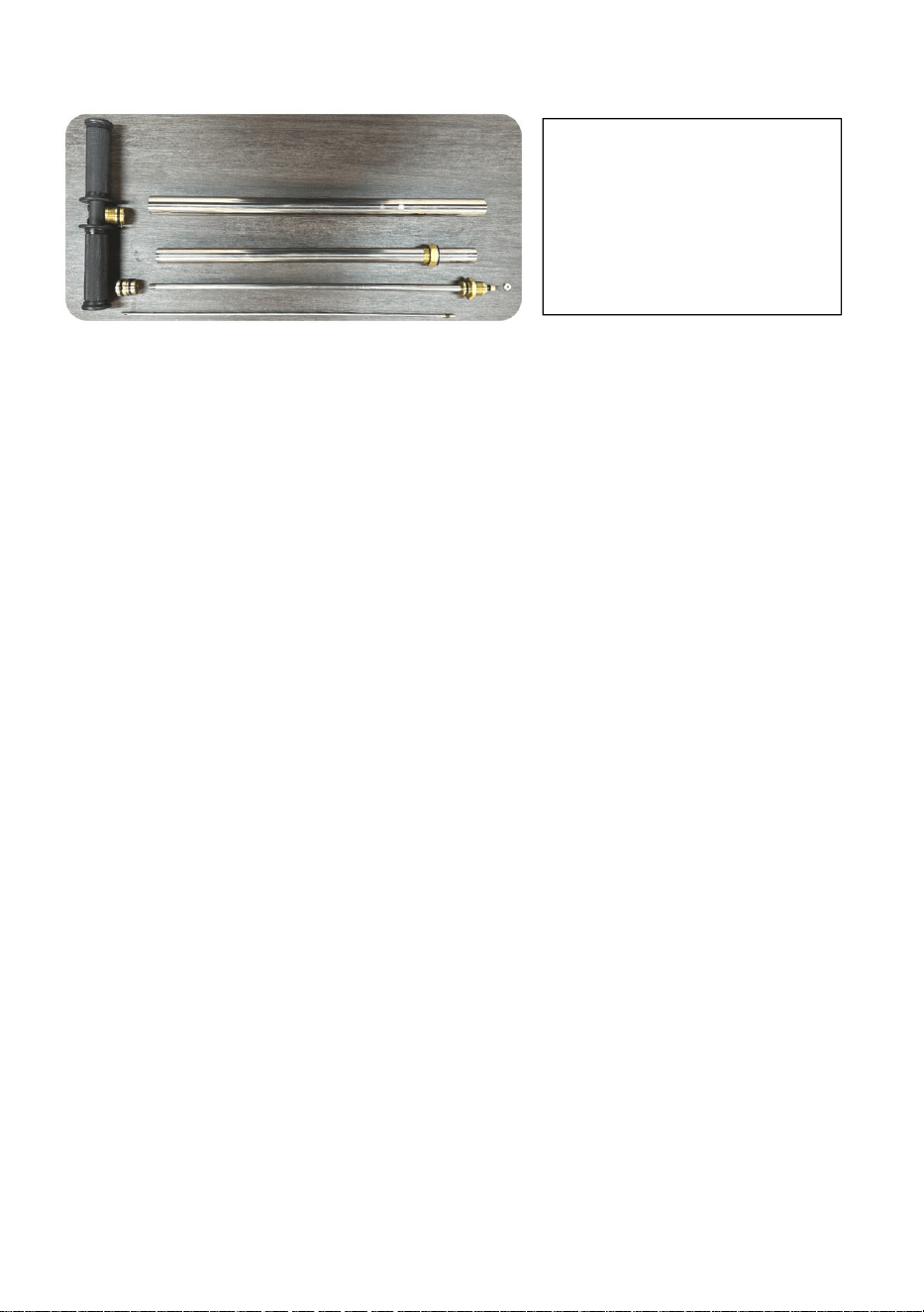
10. After the disassembly
is complete, clean the
components and check to
replace the damaged
O-rings.
7.Pull the three-stage
solid rod out of the
three-stage tube.
8.Loosen and
remove the check
valve limit screw with
a screwdriver.
9.Remove the check
valve.

- 12 -
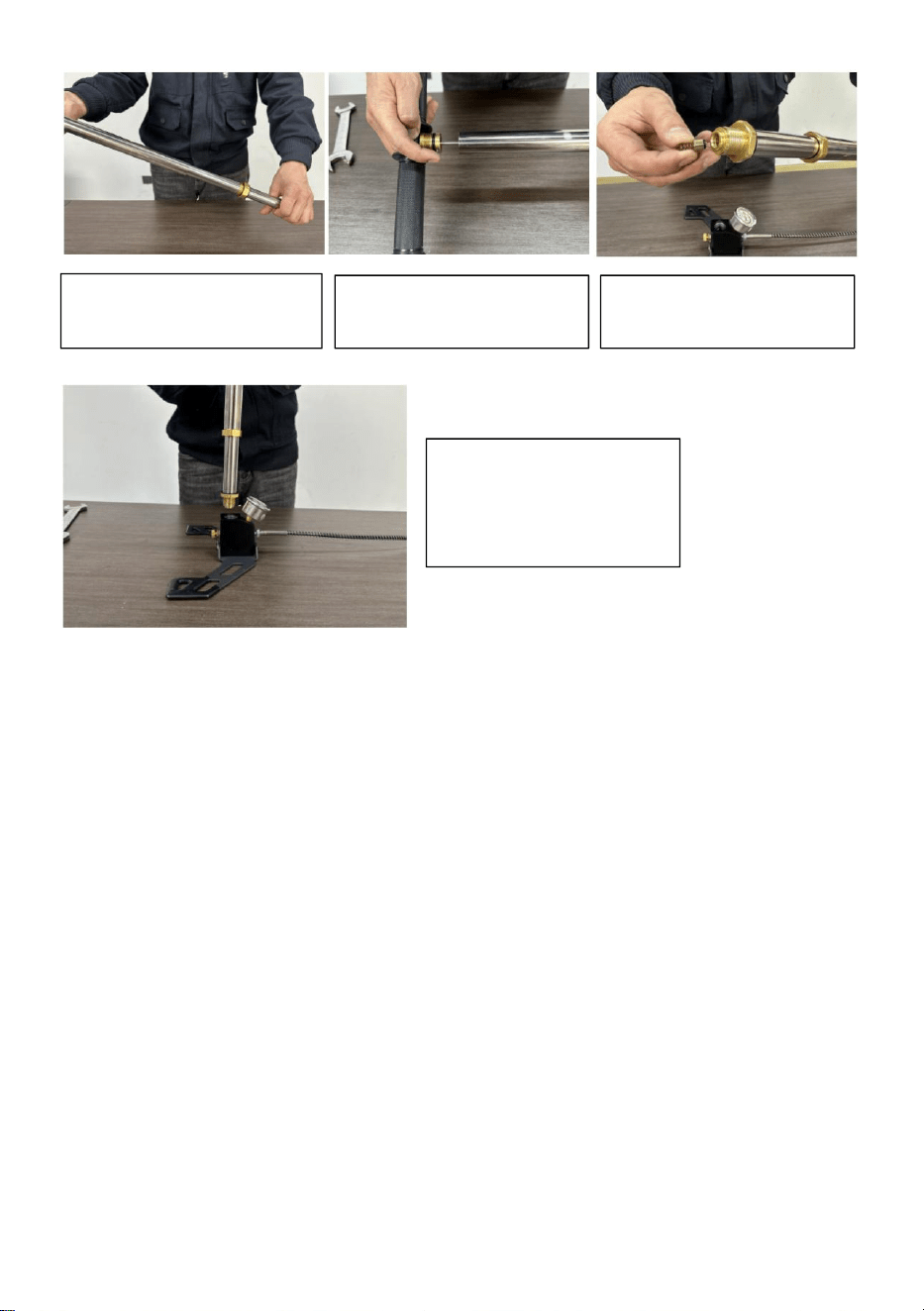
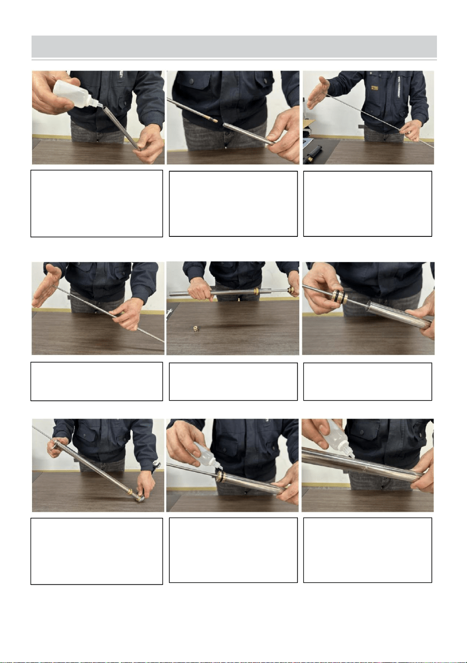
INSTALLATION PROCEDURE DIAGRAM
5.Install secondary
pipe.
1.Pour 3-4 drops of
lubricating oil into the
three-stage pipe.
6.Install the
secondary piston.
2.Put the
high-pressure piston
head easily into the
tertiary tube.
3.Pat the solid bar
from the top with your
hand.
4.Insert the solid rod
into the three-tube.
7.Tighten the
two-stage piston with
a wrench.
8.Add 3 to 4 drops of
lubricating oil as
shown.
9.Add 3~4 drops of
lubricating oil to the
secondary pipe wall.

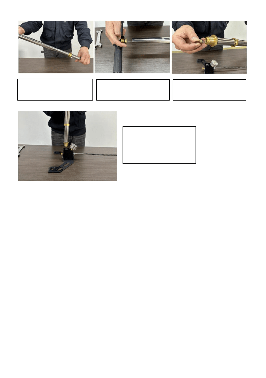
- 13 -
13.Screw the main
body into the base to
complete the
installation.
10.Install primary
pipe.
11.Install the handle.
12.Install the check
valve.

- 14 -
Manufacturer: Shanghaimuxinmuyeyouxiangongsi
Address: Shuangchenglu 803nong11hao1602A-1609shi, baoshanqu,
shanghai 200000 CN.
Imported to AUS: SIHAO PTY LTD, 1 ROKEVA STREETEASTWOOD NSW
2122 Australia
Imported to USA: Sanven Technology Ltd., Suite 250, 9166 Anaheim Place,
Rancho Cucamonga, CA 91730
REP
EC
E-CrossStu GmbH
Mainzer Landstr.69, 60329 Frankfurt am Main.
REP
UK
YH CONSULTING LIMITED.
C/O YH Consulting Limited Office 147, Centurion House,
London Road, Staines-upon-Thames, Surrey, TW18 4AX


- 2 -
Technique Certificat d'assistance et de garantie électronique
www.vevor.com/support
POMPE À AIR PCP INSTRUCTIONS
MODÈLE : DQT-3JB / DQT-3JH
We continue to be committed to provide you tools with competitive price.
"Save Half", "Half Price" or any other similar expressions used by us only represents an
estimate of savings you might benefit from buying certain tools with us compared to the major
top brands and does not necessarily mean to cover all categories of tools offered by us. You
are kindly reminded to verify carefully when you are placing an order with us if you are
actually saving half in comparison with the top major brands.
- 1 -
Have product questions? Need technical support? Please feel free to
contact us:
Technical Support and E-Warranty Certificate
www.vevor.com/support
NEED HELP? CONTACT US!
This is the original instruction, please read all manual instructions
carefully before operating. VEVOR reserves a clear interpretation of our
user manual. The appearance of the product shall be subject to the
product you received. Please forgive us that we won't inform you again if
there are any technology or software updates on our product.
PCP AIR PUMP
MODEL:DQT-3JB
MODEL:DQT-3JH

- 2 -
Avertissement - Pour réduire le risque de blessure, l'utilisateur
doit lire attentivement le manuel d'instructions.
WARNING
1. Ce manuel contient des méthodes de réparation, veuillez le
conserver en lieu sûr pour une consultation ultérieure.
2. N'utilisez pas ce produit s'il est nocif.
3. Il est interdit d’ajouter de l’huile lubrifiante aux nouveaux
équipements.
4. Desserrez d'abord la soupape de surpression une fois le gonflage
terminé et ne retirez pas le connecteur du tuyau de gaz sous
pression.
5. N'utilisez pas de pression supérieure à 31 mpa/310 bar/4 500 psi.
6. Assurez-vous que le récipient sous pression est utilisé dans la
plage de pression de sécurité et dans la période d'inspection, le
récipient sous pression doit être équipé de dispositifs antidéflagrants
de sécurité.
7. Ne laissez pas les enfants utiliser l’appareil et rangez-le dans un
endroit où les enfants ne peuvent pas le toucher.
8. N'utilisez pas ce produit ou ce manuel par des personnes qui ne le
connaissent pas.
9. N’utilisez pas ce produit sur un sol irrégulier, en pente ou glissant.
SAVE THIS MANUAL
Modèle
Principe de
compression
MWP
Base
Filtration d'huile et
d'eau

- 3 -
DQT-3JB
Compression
de niveau 3
4500 PSI
Base pliante
Filtre à huile et à eau
DQT-3JH
PART NAME

- 4 -
NON.
Nom des pièces
NON.
Nom des pièces

- 5 -
1
Vis de poignée
23
Bague d'étanchéité de
piston à deux étages
2
Poignée
24
Joint torique intérieur
inférieur du piston
secondaire
3
Corps de montage de la
poignée
25
Tube de corps de pompe
secondaire
4
Goupille de fixation à
trois leviers
26
Piston à deux étages
5
Joint d'étanchéité du
corps de soupape
d'admission
27
Bague d'étanchéité
extérieure inférieure du
piston à deux étages
6
L'admission d'air scelle
la balle
28
Tube de corps de pompe
à trois étages
7
Tube du corps de
pompe primaire
29
Tige solide haute
pression
8
Piston de premier étage
30
Tête de piston à quatre
étages
9
Joint torique extérieur
du piston primaire
31
Segment de piston à
quatre étages
10
Coussin
32
Tuyau de sortie
11
Joint torique dans le
tube secondaire
33
Filtre huile-eau
12
Corps de vanne
unidirectionnelle haute
pression
34
Élément de filtre à eau et
à huile
13
Joint d'étanchéité du
clapet anti-retour
35
Adaptateur prise rapide
14
Manomètre
36
Bague d'étanchéité à
siège rapide
15
Joint torique intérieur du
premier piston
37
Adaptateur gonflable à vis
interne 1/8 BSP
16
Joint torique extérieur à
triple tube
38
Adaptateur de valve de
pneu américain
17
Clapet anti-retour haute
pression
39
Testez rapidement la
prise
18
Ressort de soupape
anti-retour
40
Buse pour ballon
19
Vis de limite de clapet
anti-retour
41
Buse de gonflage à
flotteur
- 6 -
20
Vis de décharge de
pression
42
Aiguille à ballon pour
ballons
21
Base pliante
43
Clé Allen L
22
Joint torique intérieur
supérieur du piston
secondaire
44
Clé multi-usages
PACKING LIST
Tool set

- 7 -
INSTALLATION INSTRUCTIONS
1. Install the pressure gauge
and tighten it using a
multi-function wrench.

- 8 -
2. Install the air exhaust
pipe and tighten it using a
multifunctional wrench.
3. Install the handle and
tighten the screws with an
Allen wrench.
4. Pull the pump up and
down for 100 rounds.

- 9 -
Conseil : la pression d'essai du bouchon ne doit pas dépasser
3 500 psi. Le changement de pression dans l'espace très limité peut
provoquer la combustion de l'huile et endommager le joint du produit.
USE AND MAINTENANCE
4. Travail de lubrification
La nouvelle pompe ne nécessite pas de ravitaillement.
Remplissez-la environ une fois toutes les 1 500 fois. Il y a deux
positions à remplir et ajoutez trois gouttes d'huile à chaque position
(comme indiqué ci-dessous). Après avoir fait le plein, étirez la
pompe environ 50 fois. Lorsqu'elle n'est pas utilisée, vidangez
l'excès d'eau.
5. Install the pressure test
plug and tighten the
pressure relief screws.
6. Pull the pump up and down
to test whether the product
works normally.
Note: After filling, the
pressure relief valve must be
loosened to remove the
internal pressure before
opening the gas pipe
connector.

- 10 -
5. Méthode d'installation de la prise d'adaptateur
La prise de l'adaptateur doit être correctement installée, sinon elle est
sujette à des problèmes de blocage (comme illustré dans la Figure 1.2.3
ci-dessous).
6. Décompression
Après avoir utilisé la pompe, assurez-vous de relâcher d'abord la pression
(comme indiqué sur la figure 4 ci-dessous), puis retirez le connecteur.
N'utilisez généralement pas la pompe, essayez de ne pas maintenir de
2. Hold the primary
tube and untwist the
handle.
2. Add 3 drops of oil as
shown in Fig.
3. Tighten the handle as
shown.
4.After pulling the
handle up, add 3 drops
of oil as shown.

- 11 -
pression, le tuyau ne peut pas faire de nœuds, ne pas trop se plier, ne pas
cogner le manomètre.
TROUBLESHOOTING
Check whether the primary piston
is loose and the seal ring is
damaged.
Check whether the O-ring of the
adapter socket is 2, which must
be used to seal properly.

- 12 -
DISASSEMBLY PROCEDURE DIAGRAM
Check valve clean and check
O-ring for damage.
Check valve clean and check
O-ring for damage.
Plug quickly test whether the
product is working properly.
1.Release the wrench
and remove the pump
body.
2.Remove the handle
fixing pin.
3.Loose the primary
piston and remove
the primary tube.
Check whether the primary
piston is loose and the seal
ring is damaged.

- 13 -
4.Stuck the secondary
piston with a
multifunctional
wrench.
5.Check valve body
fixed with a wrench,
remove the two stage
piston.
6.Remove the
secondary.
10. After the disassembly
is complete, clean the
components and check to
replace the damaged
O-rings.
7.Pull the three-stage
solid rod out of the
three-stage tube.
8.Loosen and
remove the check
valve limit screw with
a screwdriver.
9.Remove the check
valve.
- 14 -
INSTALLATION PROCEDURE DIAGRAM
5.Install secondary
pipe.
1.Pour 3-4 drops of
lubricating oil into the
three-stage pipe.
6.Install the
secondary piston.
2.Put the
high-pressure piston
head easily into the
tertiary tube.
3.Pat the solid bar
from the top with your
hand.
4.Insert the solid rod
into the three-tube.
7.Tighten the
two-stage piston with
a wrench.
8.Add 3 to 4 drops of
lubricating oil as
shown.
9.Add 3~4 drops of
lubricating oil to the
secondary pipe wall.

- 15 -
13.Screw the main
body into the base to
complete the
installation.
10.Install primary
pipe.
11.Install the handle.
12.Install the check
valve.

- 16 -
Fabricant : Shanghaimuxinmuyeyouxiangongsi
Adresse : Shuangchenglu 803nong11hao1602A-1609shi, baoshanqu,
shanghai 200000 CN.
Importé en Australie : SIHAO PTY LTD, 1 ROKEVA STREET, ASTWOOD
NSW 2122 Australie
Importé aux États-Unis : Sanven Technology Ltd., Suite 250, 9166 Anaheim
Place, Rancho Cucamonga, CA 91730
REP
EC
E-CrossStu GmbH
Mainzer Landstr.69, 60329 Frankfurt am Main.
REP
UK
YH CONSULTING LIMITED.
C/O YH Consulting Limited Office 147, Centurion House,
London Road, Staines-upon-Thames, Surrey, TW18 4AX


- 2 -
Technisch Support und E-Garantie-Zertifikat
www.vevor.com/support
PCP-LUFTPUMPE ANWEISUNGEN
MODELL: DQT-3JB / DQT-3JH
We continue to be committed to provide you tools with competitive price.
"Save Half", "Half Price" or any other similar expressions used by us only represents an
estimate of savings you might benefit from buying certain tools with us compared to the major
top brands and does not necessarily mean to cover all categories of tools offered by us. You
are kindly reminded to verify carefully when you are placing an order with us if you are
actually saving half in comparison with the top major brands.

- 1 -
Have product questions? Need technical support? Please feel free to
contact us:
Technical Support and E-Warranty Certificate
www.vevor.com/support
NEED HELP? CONTACT US!
This is the original instruction, please read all manual instructions
carefully before operating. VEVOR reserves a clear interpretation of our
user manual. The appearance of the product shall be subject to the
product you received. Please forgive us that we won't inform you again if
there are any technology or software updates on our product.
PCP AIR PUMP
MODEL:DQT-3JB
MODEL:DQT-3JH
- 2 -
Warnung: Um das Verletzungsrisiko zu verringern, muss der
Benutzer die Bedienungsanleitung sorgfältig lesen.
WARNING
1. Dieses Handbuch enthält Reparaturmethoden. Bewahren Sie es zur
späteren Einsichtnahme sicher auf.
2. Verwenden Sie dieses Produkt nicht, wenn es schädlich ist.
3. Es ist verboten, neuen Geräten Schmieröl hinzuzufügen.
4. Lösen Sie nach Abschluss des Aufpumpens zunächst das
Überdruckventil und ziehen Sie den Gasleitungsanschluss nicht
unter Druck heraus.
5. Verwenden Sie keinen Druck, der 31 MPa/310 Bar/4500 psi
überschreitet.
6. Stellen Sie sicher, dass der Druckbehälter innerhalb des sicheren
Druckbereichs und innerhalb der Inspektionsfrist verwendet wird. Der
Druckbehälter muss mit explosionsgeschützten
Sicherheitsvorrichtungen ausgestattet sein.
7. Erlauben Sie Kindern nicht, das Gerät zu bedienen und bewahren
Sie es an einem Ort auf, wo Kinder es nicht erreichen können.
8. Verwenden Sie dieses Produkt oder dieses Handbuch nicht durch
Personen, die damit nicht vertraut sind.
9. Betreiben Sie dieses Produkt nicht auf unebenem, abschüssigem
oder rutschigem Boden.
SAVE THIS MANUAL
Modell
Kompression
MWP
Base
Öl- und

- 3 -
sprinzip
Wasserfiltration
DQT-3JB
Komprimieru
ng der Stufe
3
4500 PSI
Klappbarer
Sockel
Öl- und Wasserfilter
DQT-3JH
PART NAME

- 4 -
NEIN
.
Bezeichnung der Teile
NEIN
.
Bezeichnung der
Teile
- 5 -
1
Griffschraube
23
Zweistufiger
Kolbendichtring
2
Handhaben
24
Unterer innerer O-Ring
des Sekundärkolbens
3
Griffbefestigungskörper
25
Sekundäres
Pumpenkörperrohr
4
Dreihebel-Befestigungsstift
26
Zweistufiger Kolben
5
Dichtring für
Einlassventilkörper
27
Zweistufiger äußerer
Dichtungsring am
Kolbenboden
6
Lufteinlass dichtet den Ball
ab
28
Dreistufiges
Pumpengehäuse
7
Primäres
Pumpengehäuserohr
29
Hochdruck-Vollstab
8
Kolben der ersten Stufe
30
Vierstufiger
Kolbenkopf
9
Äußerer O-Ring des
Primärkolbens
31
Vierstufiger Kolbenring
10
Kissen
32
Auslassrohr
11
O-Ring im Sekundärrohr
33
Öl-Wasser-Filter
12
Hochdruck-Einwegventilkörp
er
34
Öl-Wasser-Filtereleme
nt
13
Dichtring des
Rückschlagventils
35
Adapter
Schnellsteckdose
14
Druckmessgerät
36
Schnellsitzdichtring
15
Erster innerer O-Ring des
Kolbens
37
Aufblasbarer Adapter
mit Innengewinde 1/8
BSP
16
Äußerer O-Ring des
Dreifachrohrs
38
Amerikanischer
Reifenventiladapter
17
Hochdruck-Rückschlagventil
39
Den Stecker schnell
testen
18
Ventilfeder prüfen
40
Ballondüse
19
Begrenzungsschraube des
Rückschlagventils
41
Schwimmer-Inflatordüs
e
20
Druckentlastungsschraube
42
Ballonnadel für Bälle
21
Klappbarer Sockel
43
Inbusschlüssel L
- 6 -
22
Oberer innerer O-Ring des
Sekundärkolbens
44
Mehrzweckschlüssel
PACKING LIST
Tool set

- 7 -
INSTALLATION INSTRUCTIONS
1. Install the pressure gauge
and tighten it using a
multi-function wrench.
2. Install the air exhaust
pipe and tighten it using a
multifunctional wrench.
- 8 -
3. Install the handle and
tighten the screws with an
Allen wrench.
4. Pull the pump up and
down for 100 rounds.
5. Install the pressure test
plug and tighten the
pressure relief screws.
- 9 -
Tipp: Der Prüfdruck des Stopfens sollte 3500 psi nicht
überschreiten. Die sehr begrenzte Druckänderung kann dazu führen, dass
das Öl verbrennt und die Produktdichtung beschädigt wird.
USE AND MAINTENANCE
7. Schmierjob
Die neue Pumpe muss nicht nachgefüllt werden. Füllen Sie etwa alle
1500 Mal nach. Es gibt zwei Stellen, die nachgefüllt werden müssen.
Geben Sie an jede Stelle drei Tropfen Öl (siehe unten). Dehnen Sie
die Pumpe nach dem Auffüllen etwa 50 Mal. Lassen Sie
überschüssiges Wasser ab, wenn sie nicht verwendet wird.
6. Pull the pump up and down
to test whether the product
works normally.
Note: After filling, the
pressure relief valve must be
loosened to remove the
internal pressure before
opening the gas pipe
connector.
3. Hold the primary
tube and untwist the
handle.
- 10 -
8. Installationsmethode für Adapterbuchsen
Die Adapterbuchse muss ordnungsgemäß installiert sein, da es sonst zu
Verstopfungen kommen kann (siehe Abbildung 1.2.3 unten).
9. Dekompression
Nach der Verwendung der Pumpe müssen Sie zuerst den Druck ablassen
(siehe Abbildung 4 unten) und dann den Anschluss entfernen. Verwenden
Sie die Pumpe normalerweise nicht. Versuchen Sie, keinen Druck
aufrechtzuerhalten. Der Schlauch darf nicht verknoten, nicht übermäßig
gebogen werden und stoßen Sie nicht gegen das Manometer.
2. Add 3 drops of oil as
shown in Fig.
3. Tighten the handle as
shown.
4.After pulling the
handle up, add 3 drops
of oil as shown.

- 11 -
TROUBLESHOOTING
Check whether the primary piston
is loose and the seal ring is
damaged.
Check whether the O-ring of the
adapter socket is 2, which must
be used to seal properly.

- 12 -
DISASSEMBLY PROCEDURE DIAGRAM
Check valve clean and check
O-ring for damage.
Check valve clean and check
O-ring for damage.
Plug quickly test whether the
product is working properly.
1.Release the wrench
and remove the pump
body.
2.Remove the handle
fixing pin.
3.Loose the primary
piston and remove
the primary tube.
Check whether the primary
piston is loose and the seal
ring is damaged.

- 13 -
4.Stuck the secondary
piston with a
multifunctional
wrench.
5.Check valve body
fixed with a wrench,
remove the two stage
piston.
6.Remove the
secondary.
10. After the disassembly
is complete, clean the
components and check to
replace the damaged
O-rings.
7.Pull the three-stage
solid rod out of the
three-stage tube.
8.Loosen and
remove the check
valve limit screw with
a screwdriver.
9.Remove the check
valve.

- 14 -
INSTALLATION PROCEDURE DIAGRAM
5.Install secondary
pipe.
1.Pour 3-4 drops of
lubricating oil into the
three-stage pipe.
6.Install the
secondary piston.
2.Put the
high-pressure piston
head easily into the
tertiary tube.
3.Pat the solid bar
from the top with your
hand.
4.Insert the solid rod
into the three-tube.
7.Tighten the
two-stage piston with
a wrench.
8.Add 3 to 4 drops of
lubricating oil as
shown.
9.Add 3~4 drops of
lubricating oil to the
secondary pipe wall.

- 15 -
13.Screw the main
body into the base to
complete the
installation.
10.Install primary
pipe.
11.Install the handle.
12.Install the check
valve.

- 16 -
Hersteller: Shanghaimuxinmuyeyouxiangongsi
Adresse: Shuangchenglu 803nong11hao1602A-1609shi, baoshanqu,
Shanghai 200000 CN.
Nach AUS importiert: SIHAO PTY LTD, 1 ROKEVA STREETEASTWOOD
NSW 2122 Australien
Importiert in die USA: Sanven Technology Ltd., Suite 250, 9166 Anaheim
Place, Rancho Cucamonga, CA 91730
REP
EC
E-CrossStu GmbH
Mainzer Landstr.69, 60329 Frankfurt am Main.
REP
UK
YH CONSULTING LIMITED.
C/O YH Consulting Limited Office 147, Centurion House,
London Road, Staines-upon-Thames, Surrey, TW18 4AX


- 2 -
Tecnico Supporto e certificato di garanzia elettronica
www.vevor.com/support
POMPA AD ARIA PCP ISTRUZIONI
MODELLO: DQT-3JB / DQT-3JH
We continue to be committed to provide you tools with competitive price.
"Save Half", "Half Price" or any other similar expressions used by us only represents an
estimate of savings you might benefit from buying certain tools with us compared to the major
top brands and does not necessarily mean to cover all categories of tools offered by us. You
are kindly reminded to verify carefully when you are placing an order with us if you are
actually saving half in comparison with the top major brands.

- 1 -
Have product questions? Need technical support? Please feel free to
contact us:
Technical Support and E-Warranty Certificate
www.vevor.com/support
NEED HELP? CONTACT US!
This is the original instruction, please read all manual instructions
carefully before operating. VEVOR reserves a clear interpretation of our
user manual. The appearance of the product shall be subject to the
product you received. Please forgive us that we won't inform you again if
there are any technology or software updates on our product.
PCP AIR PUMP
MODEL:DQT-3JB
MODEL:DQT-3JH

- 2 -
Attenzione: per ridurre il rischio di lesioni, l'utente deve leggere
attentamente il manuale di istruzioni.
WARNING
1. Questo manuale contiene metodi di riparazione, conservarlo in un
luogo sicuro per consultazioni future.
2. Non utilizzare questo prodotto se è dannoso.
3. È vietato aggiungere olio lubrificante alle nuove apparecchiature.
4. Una volta completato il gonfiaggio, allentare innanzitutto la valvola
di sicurezza e non estrarre il connettore del tubo del gas sotto
pressione.
5. Non utilizzare una pressione superiore a 31 mpa/310 bar/4500 psi.
6. Assicurarsi che il contenitore pressurizzato venga utilizzato entro
l'intervallo di pressione sicuro e durante il periodo di ispezione; il
contenitore pressurizzato deve essere dotato di dispositivi di
sicurezza antideflagranti.
7. Non consentire ai bambini di utilizzare il dispositivo e conservarlo
in un luogo dove i bambini non possano toccarlo.
8. Non far utilizzare questo prodotto o questo manuale a persone che
non ne hanno familiarità.
9. Non utilizzare il prodotto su terreni irregolari, in pendenza o
scivolosi.
SAVE THIS MANUAL
Modello
Principio di
compression
MWP
Base
Filtrazione di olio e
acqua

- 3 -
e
MODELLO
DQT-3JB
Compression
e di livello 3
4500 PSI
Base
pieghevole
Filtro olio e acqua
MODELL
O
DQT-3JH
PART NAME

- 4 -
NO.
Nome delle parti
NO.
Nome delle parti

- 5 -
1
Vite della maniglia
23
Anello di tenuta del pistone
a due stadi
2
Maniglia
24
O-ring interno inferiore
pistone secondario
3
Corpo di montaggio della
maniglia
25
Tubo del corpo della
pompa secondaria
4
Perno di fissaggio a tre
leve
26
Pistone a due stadi
5
Anello di tenuta del
corpo valvola di
aspirazione
27
Anello di tenuta esterno
inferiore del pistone a due
stadi
6
La presa d'aria sigilla la
palla
28
Tubo del corpo della
pompa a tre stadi
7
Tubo del corpo della
pompa primaria
29
Asta piena ad alta
pressione
8
Pistone del primo stadio
30
Testa del pistone a quattro
stadi
9
O-ring esterno del
pistone primario
31
Fascia elastica a quattro
stadi
10
Cuscino
32
Tubo di uscita
11
O-ring nel tubo
secondario
33
Filtro olio-acqua
12
Corpo valvola
unidirezionale ad alta
pressione
34
Elemento filtro acqua olio
13
Anello di tenuta della
valvola di ritegno
35
Adattatore presa rapida
14
Manometro
36
Anello di tenuta a sede
rapida
15
Primo O-ring interno del
pistone
37
Adattatore gonfiabile con
vite interna da 1/8 BSP
16
O-ring esterno a triplo
tubo
38
Adattatore valvola
pneumatico americano
17
Valvola di ritegno ad alta
pressione
39
Provare rapidamente la
spina
18
Molla della valvola di
ritegno
40
Ugello a palloncino
19
Vite di limite della valvola
di ritegno
41
Ugello gonfiatore
galleggiante
20
Vite di scarico della
42
Ago per palloncini per
- 6 -
pressione
palline
21
Base pieghevole
43
Chiave a brugola L
22
O-ring interno superiore
pistone secondario
44
Chiave multiuso
PACKING LIST
Tool set
- 7 -
INSTALLATION INSTRUCTIONS
1. Install the pressure gauge
and tighten it using a
multi-function wrench.

- 8 -
2. Install the air exhaust
pipe and tighten it using a
multifunctional wrench.
3. Install the handle and
tighten the screws with an
Allen wrench.
4. Pull the pump up and
down for 100 rounds.
- 9 -
Suggerimento: la pressione di prova del tappo non deve superare i
3500 psi. La variazione di pressione dello spazio molto limitata può
causare la combustione dell'olio e danneggiare la guarnizione del prodotto.
USE AND MAINTENANCE
10. Lavoro di lubrificazione
La nuova pompa non richiede rifornimento. Riempire una volta ogni
1500 volte circa, ci sono due posizioni che devono essere riempite e
aggiungere tre gocce di olio in ogni posizione (come mostrato di
seguito). Dopo il riempimento, allungare la pompa circa 50 volte.
Quando non è in uso, drenare l'acqua in eccesso.
5. Install the pressure test
plug and tighten the
pressure relief screws.
6. Pull the pump up and down
to test whether the product
works normally.
Note: After filling, the
pressure relief valve must be
loosened to remove the
internal pressure before
opening the gas pipe
connector.

- 10 -
11. Metodo di installazione della presa dell'adattatore
La presa dell'adattatore deve essere installata correttamente, altrimenti è
soggetta a problemi di blocco (come mostrato nella Figura 1.2.3 di
seguito).
12. Decompressione
Dopo aver utilizzato la pompa, assicurarsi di scaricare prima la pressione
(come mostrato nella Figura 4 di seguito), quindi rimuovere il connettore.
Di solito non utilizzare la pompa, si prega di cercare di non mantenere
4. Hold the primary
tube and untwist the
handle.
2. Add 3 drops of oil as
shown in Fig.
3. Tighten the handle as
shown.
4.After pulling the
handle up, add 3 drops
of oil as shown.

- 11 -
alcuna pressione, il tubo non può annodarsi, non piegarsi eccessivamente,
non urtare il manometro.
TROUBLESHOOTING
Check whether the primary piston
is loose and the seal ring is
damaged.
Check whether the O-ring of the
adapter socket is 2, which must
be used to seal properly.

- 12 -
DISASSEMBLY PROCEDURE DIAGRAM
Check valve clean and check
O-ring for damage.
Check valve clean and check
O-ring for damage.
Plug quickly test whether the
product is working properly.
1.Release the wrench
and remove the pump
body.
2.Remove the handle
fixing pin.
3.Loose the primary
piston and remove
the primary tube.
Check whether the primary
piston is loose and the seal
ring is damaged.

- 13 -
4.Stuck the secondary
piston with a
multifunctional
wrench.
5.Check valve body
fixed with a wrench,
remove the two stage
piston.
6.Remove the
secondary.
10. After the disassembly
is complete, clean the
components and check to
replace the damaged
O-rings.
7.Pull the three-stage
solid rod out of the
three-stage tube.
8.Loosen and
remove the check
valve limit screw with
a screwdriver.
9.Remove the check
valve.

- 14 -
INSTALLATION PROCEDURE DIAGRAM
5.Install secondary
pipe.
1.Pour 3-4 drops of
lubricating oil into the
three-stage pipe.
6.Install the
secondary piston.
2.Put the
high-pressure piston
head easily into the
tertiary tube.
3.Pat the solid bar
from the top with your
hand.
4.Insert the solid rod
into the three-tube.
7.Tighten the
two-stage piston with
a wrench.
8.Add 3 to 4 drops of
lubricating oil as
shown.
9.Add 3~4 drops of
lubricating oil to the
secondary pipe wall.
- 15 -
13.Screw the main
body into the base to
complete the
installation.
10.Install primary
pipe.
11.Install the handle.
12.Install the check
valve.

- 16 -
Produttore: Shanghaimuxinmuyeyouxiangongsi
Indirizzo: Shuangchenglu 803nong11hao1602A-1609shi, baoshanqu,
shanghai 200000 CN.
Importato in AUS: SIHAO PTY LTD, 1 ROKEVA STREETEASTWOOD NSW
2122 Australia
Importato negli USA: Sanven Technology Ltd., Suite 250, 9166 Anaheim
Place, Rancho Cucamonga, CA 91730
REP
EC
E-CrossStu GmbH
Mainzer Landstr.69, 60329 Frankfurt am Main.
REP
UK
YH CONSULTING LIMITED.
C/O YH Consulting Limited Office 147, Centurion House,
London Road, Staines-upon-Thames, Surrey, TW18 4AX


- 2 -
Técnico Certificado de soporte y garantía electrónica
www.vevor.com/support
BOMBA DE AIRE PCP INSTRUCCIONES
MODELO: DQT-3JB / DQT-3JH
We continue to be committed to provide you tools with competitive price.
"Save Half", "Half Price" or any other similar expressions used by us only represents an
estimate of savings you might benefit from buying certain tools with us compared to the major
top brands and does not necessarily mean to cover all categories of tools offered by us. You
are kindly reminded to verify carefully when you are placing an order with us if you are
actually saving half in comparison with the top major brands.

- 1 -
Have product questions? Need technical support? Please feel free to
contact us:
Technical Support and E-Warranty Certificate
www.vevor.com/support
NEED HELP? CONTACT US!
This is the original instruction, please read all manual instructions
carefully before operating. VEVOR reserves a clear interpretation of our
user manual. The appearance of the product shall be subject to the
product you received. Please forgive us that we won't inform you again if
there are any technology or software updates on our product.
PCP AIR PUMP
MODEL:DQT-3JB
MODEL:DQT-3JH
- 2 -
Advertencia: Para reducir el riesgo de lesiones, el usuario debe
leer atentamente el manual de instrucciones.
WARNING
1. Este manual contiene métodos de reparación, consérvelo para
consultarlo en el futuro.
2. No utilice este producto cuando sea nocivo.
3. Está prohibido agregar aceite lubricante a equipos nuevos.
4. Primero afloje la válvula de alivio de presión cuando se complete el
inflado y no tire del conector del tubo de gas bajo presión.
5. No utilice una presión que supere los 31 mpa/310 bar/4500 psi.
6. Asegúrese de que el contenedor presurizado se utilice dentro del
rango de presión seguro y dentro del período de inspección, el
contenedor presurizado debe estar equipado con dispositivos de
seguridad a prueba de explosiones.
7. No permita que los niños operen el dispositivo y guárdelo en un
lugar donde no puedan tocarlo.
8. No utilice este producto ni este manual por personas que no estén
familiarizadas con él.
9. No utilice este producto en terrenos irregulares, inclinados o
resbaladizos.
SAVE THIS MANUAL
Modelo
Principio de
compresión
Program
a de
trabajo
Base
Filtración de aceite y
agua

- 3 -
móvil
DQT-3JB
Compresión
de nivel 3
4500 PSI
Base
plegable
Filtro de aceite y agua
DQT-3JH
PART NAME
- 4 -
NO.
Nombre de las partes
NO.
Nombre de las partes

- 5 -
1
Tornillo de manija
23
Anillo de sello de pistón de
dos etapas
2
Manejar
24
Junta tórica interior inferior
del pistón secundario
3
Cuerpo de montaje del
mango
25
Tubo del cuerpo de la
bomba secundaria
4
Pasador de fijación de
tres palancas
26
Pistón de dos etapas
5
Anillo de sellado del
cuerpo de la válvula de
admisión
27
Anillo de sello exterior
inferior del pistón de dos
etapas
6
La entrada de aire sella
la bola.
28
Tubo del cuerpo de la
bomba de tres etapas
7
Tubo del cuerpo de la
bomba primaria
29
Varilla sólida de alta
presión
8
Pistón de primera etapa
30
Cabezal de pistón de
cuatro etapas
9
Junta tórica exterior del
pistón primario
31
Anillo de pistón de cuatro
etapas
10
Almohadón
32
Tubo de salida
11
Junta tórica en tubo
secundario
33
Filtro de aceite y agua
12
Cuerpo de válvula
unidireccional de alta
presión
34
Elemento de filtro de agua
y aceite
13
Anillo de sello de válvula
de retención
35
Adaptador de enchufe
rápido
14
Manómetro
36
Anillo de sellado de
asiento rápido
15
Primera junta tórica
interior del pistón
37
Adaptador inflable con
rosca interna BSP de 1/8"
16
Junta tórica exterior de
triple tubo
38
Adaptador de válvula de
neumático americano
17
Válvula de retención de
alta presión
39
Pruebe el enchufe
rápidamente
18
Resorte de válvula de
retención
40
Boquilla para globo
19
Tornillo de límite de la
válvula de retención
41
Boquilla de inflado flotante
20
Tornillo de alivio de
42
Aguja para globos para
- 6 -
presión
pelotas
21
Base plegable
43
Llave Allen L
22
Junta tórica interior
superior del pistón
secundario
44
Llave multiusos
PACKING LIST
Tool set

- 7 -
INSTALLATION INSTRUCTIONS
1. Install the pressure gauge
and tighten it using a
multi-function wrench.
- 8 -
2. Install the air exhaust
pipe and tighten it using a
multifunctional wrench.
3. Install the handle and
tighten the screws with an
Allen wrench.
4. Pull the pump up and
down for 100 rounds.

- 9 -
Consejo: La presión de prueba del tapón no debe superar los 3500
psi. El cambio de presión en el espacio muy limitado puede provocar que
el aceite se queme y dañe el sello del producto.
USE AND MAINTENANCE
13. Trabajo de lubricación
La nueva bomba no necesita recargarse. Llénela una vez cada 1500
veces aproximadamente, hay dos posiciones que deben llenarse y
agregue tres gotas de aceite en cada posición (como se muestra a
continuación). Después de llenarla, estire la bomba unas 50 veces.
Cuando no esté en uso, drene el exceso de agua.
5. Install the pressure test
plug and tighten the
pressure relief screws.
6. Pull the pump up and down
to test whether the product
works normally.
Note: After filling, the
pressure relief valve must be
loosened to remove the
internal pressure before
opening the gas pipe
connector.

- 10 -
14. Método de instalación del zócalo del adaptador
El enchufe del adaptador debe estar instalado correctamente, de lo
contrario es propenso a problemas de bloqueo (como se muestra en la
Figura 1.2.3 a continuación).
15. Descompresión
Después de utilizar la bomba, asegúrese de aliviar la presión primero
(como se muestra en la Figura 4 a continuación) y luego retire el conector.
Por lo general, no utilice la bomba, intente mantenerla sin presión, la
5. Hold the primary
tube and untwist the
handle.
2. Add 3 drops of oil as
shown in Fig.
3. Tighten the handle as
shown.
4.After pulling the
handle up, add 3 drops
of oil as shown.
- 11 -
manguera no debe tener nudos, no debe doblarse excesivamente y no
debe golpear el manómetro.
TROUBLESHOOTING
Check whether the primary piston
is loose and the seal ring is
damaged.
Check whether the O-ring of the
adapter socket is 2, which must
be used to seal properly.

- 12 -
DISASSEMBLY PROCEDURE DIAGRAM
Check valve clean and check
O-ring for damage.
Check valve clean and check
O-ring for damage.
Plug quickly test whether the
product is working properly.
1.Release the wrench
and remove the pump
body.
2.Remove the handle
fixing pin.
3.Loose the primary
piston and remove
the primary tube.
Check whether the primary
piston is loose and the seal
ring is damaged.

- 13 -
4.Stuck the secondary
piston with a
multifunctional
wrench.
5.Check valve body
fixed with a wrench,
remove the two stage
piston.
6.Remove the
secondary.
10. After the disassembly
is complete, clean the
components and check to
replace the damaged
O-rings.
7.Pull the three-stage
solid rod out of the
three-stage tube.
8.Loosen and
remove the check
valve limit screw with
a screwdriver.
9.Remove the check
valve.

- 14 -
INSTALLATION PROCEDURE DIAGRAM
5.Install secondary
pipe.
1.Pour 3-4 drops of
lubricating oil into the
three-stage pipe.
6.Install the
secondary piston.
2.Put the
high-pressure piston
head easily into the
tertiary tube.
3.Pat the solid bar
from the top with your
hand.
4.Insert the solid rod
into the three-tube.
7.Tighten the
two-stage piston with
a wrench.
8.Add 3 to 4 drops of
lubricating oil as
shown.
9.Add 3~4 drops of
lubricating oil to the
secondary pipe wall.

- 15 -
13.Screw the main
body into the base to
complete the
installation.
10.Install primary
pipe.
11.Install the handle.
12.Install the check
valve.

- 16 -
Fabricante: Shanghaimuxinmuyeyouxiangongsi
Dirección: Shuangchenglu 803nong11hao1602A-1609shi, baoshanqu,
shanghai 200000 CN.
Importado a AUS: SIHAO PTY LTD, 1 ROKEVA STREETEASTWOOD NSW
2122 Australia
Importado a EE. UU.: Sanven Technology Ltd., Suite 250, 9166 Anaheim
Place, Rancho Cucamonga, CA 91730
REP
EC
E-CrossStu GmbH
Mainzer Landstr.69, 60329 Frankfurt am Main.
REP
UK
YH CONSULTING LIMITED.
C/O YH Consulting Limited Office 147, Centurion House,
London Road, Staines-upon-Thames, Surrey, TW18 4AX


- 2 -
Techniczny Wsparcie i certyfikat e-gwarancji
www.vevor.com/support
POMPA POWIETRZA PCP INSTRUKCJE
MODELE: DQT-3JB / DQT-3JH
We continue to be committed to provide you tools with competitive price.
"Save Half", "Half Price" or any other similar expressions used by us only represents an
estimate of savings you might benefit from buying certain tools with us compared to the major
top brands and does not necessarily mean to cover all categories of tools offered by us. You
are kindly reminded to verify carefully when you are placing an order with us if you are
actually saving half in comparison with the top major brands.

- 1 -
Have product questions? Need technical support? Please feel free to
contact us:
Technical Support and E-Warranty Certificate
www.vevor.com/support
NEED HELP? CONTACT US!
This is the original instruction, please read all manual instructions
carefully before operating. VEVOR reserves a clear interpretation of our
user manual. The appearance of the product shall be subject to the
product you received. Please forgive us that we won't inform you again if
there are any technology or software updates on our product.
PCP AIR PUMP
MODEL:DQT-3JB
MODEL:DQT-3JH

- 2 -
Ostrzeżenie: Aby zminimalizować ryzyko obrażeń, użytkownik
powinien uważnie przeczytać instrukcję obsługi.
WARNING
1. W niniejszej instrukcji opisano metody naprawy, prosimy
zachować ją do przyszłego użytku.
2. Nie należy używać tego produktu, jeżeli jest szkodliwy.
3. Zabrania się dodawania oleju smarującego do nowego sprzętu.
4. Po zakończeniu pompowania należy najpierw poluzować zawór
bezpieczeństwa i nie wyciągać złącza przewodu gazowego pod
ciśnieniem.
5. Nie należy stosować ciśnienia przekraczającego 31 mpa/310
bar/4500 psi.
6. Należy upewnić się, że pojemnik ciśnieniowy jest używany w
bezpiecznym zakresie ciśnienia oraz w okresie kontroli; pojemnik
ciśnieniowy musi być wyposażony w urządzenia zabezpieczające
przed wybuchem.
7. Nie pozwalaj dzieciom obsługiwać urządzenia i przechowuj je w
miejscu, w którym nie będą miały do niego dostępu.
8. Nie używaj tego produktu ani tej instrukcji przez osoby, które nie są
z nimi zaznajomione.
9. Nie używaj tego produktu na nierównym, pochyłym lub śliskim
podłożu.
SAVE THIS MANUAL
Model
Zasada
MWP
Opierać
Filtracja oleju i wody

- 3 -
kompresji
DQT-3JB
Kompresja
poziomu 3
4500 PSI
Podstawa
składana
Filtr oleju i wody
DQT-3JH
PART NAME

- 4 -
NIE.
Nazwa części
NIE.
Nazwa części

- 5 -
1
Śruba uchwytu
23
Dwustopniowy pierścień
uszczelniający tłoka
2
Uchwyt
24
Pierścień uszczelniający
wewnętrzny dolnego tłoka
wtórnego
3
Uchwyt montażowy
korpusu
25
Rurka korpusu pompy
wtórnej
4
Trzy dźwigniowe
sworznie mocujące
26
Tłok dwustopniowy
5
Pierścień uszczelniający
korpusu zaworu
dolotowego
27
Dwustopniowy pierścień
uszczelniający dolny
zewnętrzny tłoka
6
Wlot powietrza
uszczelnia piłkę
28
Rura korpusu pompy
trzystopniowej
7
Rura korpusu pompy
głównej
29
Pręt lity
wysokociśnieniowy
8
Tłok pierwszego stopnia
30
Głowica tłokowa
czterostopniowa
9
Pierwotny zewnętrzny
pierścień uszczelniający
tłoka
31
Pierścień tłokowy
czterostopniowy
10
Poduszka
32
Rura wyjściowa
11
Pierścień uszczelniający
w rurze wtórnej
33
Filtr olejowo-wodny
12
Korpus zaworu
jednokierunkowego
wysokiego ciśnienia
34
Wkład filtra oleju i wody
13
Pierścień uszczelniający
zaworu zwrotnego
35
Gniazdo adaptera
szybkiego
14
Manometr
36
Pierścień uszczelniający
szybkiego montażu
15
Pierwszy wewnętrzny
pierścień uszczelniający
tłoka
37
Adapter dmuchany z
gwintem wewnętrznym
BSP 1/8
16
Zewnętrzny pierścień
uszczelniający potrójnej
rurki
38
Amerykański adapter do
zaworów oponowych
17
Zawór zwrotny
wysokiego ciśnienia
39
Szybko przetestuj wtyczkę
18
Sprężyna zaworu
zwrotnego
40
Dysza do balonu
- 6 -
19
Śruba ograniczająca
zaworu zwrotnego
41
Dysza do pompowania
pływaka
20
Śruba odciążająca
ciśnienie
42
Igła do balonów
21
Podstawa składana
43
Klucz imbusowy L
22
Górny wewnętrzny
pierścień uszczelniający
tłoka wtórnego
44
Klucz uniwersalny
PACKING LIST
Tool set

- 7 -
INSTALLATION INSTRUCTIONS
1. Install the pressure gauge
and tighten it using a
multi-function wrench.

- 8 -
2. Install the air exhaust
pipe and tighten it using a
multifunctional wrench.
3. Install the handle and
tighten the screws with an
Allen wrench.
4. Pull the pump up and
down for 100 rounds.

- 9 -
Wskazówka: Ciśnienie testowe wtyczki nie powinno przekraczać
3500 psi. Bardzo ograniczona zmiana ciśnienia w przestrzeni może
spowodować spalenie oleju i uszkodzenie uszczelnienia produktu.
USE AND MAINTENANCE
16. Praca w Lube
Nowa pompa nie wymaga uzupełniania paliwa. Napełniaj raz na
około 1500 razy, są dwa miejsca, które należy napełnić, i dodaj trzy
krople oleju do każdego miejsca (jak pokazano poniżej). Po
napełnieniu rozciągnij pompę około 50 razy. Gdy nie jest używana,
spuść nadmiar wody.
5. Install the pressure test
plug and tighten the
pressure relief screws.
6. Pull the pump up and down
to test whether the product
works normally.
Note: After filling, the
pressure relief valve must be
loosened to remove the
internal pressure before
opening the gas pipe
connector.
- 10 -
17. Sposób montażu gniazda adaptera
Gniazdo adaptera powinno być prawidłowo zamontowane, w przeciwnym
razie jest narażone na zatykanie (jak pokazano na rysunku 1.2.3 poniżej).
18. Dekompresja
Po użyciu pompki, pamiętaj o tym, aby najpierw uwolnić ciśnienie (jak
pokazano na rysunku 4 poniżej), a następnie odłącz złącze. Zazwyczaj nie
używaj pompki, staraj się nie utrzymywać ciśnienia, wąż nie może się
zaplątać, nie może się nadmiernie wyginać, nie uderzaj w manometr.
6. Hold the primary
tube and untwist the
handle.
2. Add 3 drops of oil as
shown in Fig.
3. Tighten the handle as
shown.
4.After pulling the
handle up, add 3 drops
of oil as shown.
- 11 -
TROUBLESHOOTING
Check whether the primary piston
is loose and the seal ring is
damaged.
Check whether the O-ring of the
adapter socket is 2, which must
be used to seal properly.
- 12 -
DISASSEMBLY PROCEDURE DIAGRAM
Check valve clean and check
O-ring for damage.
Check valve clean and check
O-ring for damage.
Plug quickly test whether the
product is working properly.
1.Release the wrench
and remove the pump
body.
2.Remove the handle
fixing pin.
3.Loose the primary
piston and remove
the primary tube.
Check whether the primary
piston is loose and the seal
ring is damaged.

- 13 -
4.Stuck the secondary
piston with a
multifunctional
wrench.
5.Check valve body
fixed with a wrench,
remove the two stage
piston.
6.Remove the
secondary.
10. After the disassembly
is complete, clean the
components and check to
replace the damaged
O-rings.
7.Pull the three-stage
solid rod out of the
three-stage tube.
8.Loosen and
remove the check
valve limit screw with
a screwdriver.
9.Remove the check
valve.
- 14 -
INSTALLATION PROCEDURE DIAGRAM
5.Install secondary
pipe.
1.Pour 3-4 drops of
lubricating oil into the
three-stage pipe.
6.Install the
secondary piston.
2.Put the
high-pressure piston
head easily into the
tertiary tube.
3.Pat the solid bar
from the top with your
hand.
4.Insert the solid rod
into the three-tube.
7.Tighten the
two-stage piston with
a wrench.
8.Add 3 to 4 drops of
lubricating oil as
shown.
9.Add 3~4 drops of
lubricating oil to the
secondary pipe wall.
- 15 -
13.Screw the main
body into the base to
complete the
installation.
10.Install primary
pipe.
11.Install the handle.
12.Install the check
valve.

- 16 -
Producent: Shanghaimuxinmuyeyouxiangongsi
Adres: Shuangchenglu 803nong11hao1602A-1609shi, baoshanqu, szanghaj
200000 CN.
Importowane do AUS: SIHAO PTY LTD, 1 ROKEVA STREETEASTWOOD
NSW 2122 Australia
Importowane do USA: Sanven Technology Ltd., Suite 250, 9166 Anaheim
Place, Rancho Cucamonga, CA 91730
REP
EC
E-CrossStu GmbH
Mainzer Landstr.69, 60329 Frankfurt am Main.
REP
UK
YH CONSULTING LIMITED.
C/O YH Consulting Limited Office 147, Centurion House,
London Road, Staines-upon-Thames, Surrey, TW18 4AX


- 2 -
Technisch Ondersteuning en E-garantiecertificaat
www.vevor.com/support
PCP LUCHTPOMP INSTRUCTIES
MODEL: DQT-3JB / DQT-3JH
We continue to be committed to provide you tools with competitive price.
"Save Half", "Half Price" or any other similar expressions used by us only represents an
estimate of savings you might benefit from buying certain tools with us compared to the major
top brands and does not necessarily mean to cover all categories of tools offered by us. You
are kindly reminded to verify carefully when you are placing an order with us if you are
actually saving half in comparison with the top major brands.
- 1 -
Have product questions? Need technical support? Please feel free to
contact us:
Technical Support and E-Warranty Certificate
www.vevor.com/support
NEED HELP? CONTACT US!
This is the original instruction, please read all manual instructions
carefully before operating. VEVOR reserves a clear interpretation of our
user manual. The appearance of the product shall be subject to the
product you received. Please forgive us that we won't inform you again if
there are any technology or software updates on our product.
PCP AIR PUMP
MODEL:DQT-3JB
MODEL:DQT-3JH
- 2 -
Waarschuwing: om het risico op letsel te verkleinen, moet de
gebruiker de gebruiksaanwijzing zorgvuldig lezen.
WARNING
1. Deze handleiding bevat reparatiemethoden. Bewaar deze op een
veilige plaats voor toekomstig gebruik.
2. Gebruik dit product niet als het schadelijk is.
3. Het is verboden smeerolie toe te voegen aan nieuwe apparatuur.
4. Draai eerst het overdrukventiel los nadat het oppompen is voltooid.
Trek de gasleidingaansluiting er niet uit als de druk nog steeds hoog
is.
5. Gebruik geen druk die hoger is dan 31 MPa/310 bar/4500 psi.
6. Zorg ervoor dat de drukcontainer binnen het veilige drukbereik
wordt gebruikt en dat de drukcontainer binnen de inspectieperiode is
uitgerust met explosieveilige veiligheidsvoorzieningen.
7. Laat kinderen het apparaat niet bedienen en bewaar het op een plek
waar kinderen er niet bij kunnen.
8. Laat dit product en deze handleiding niet gebruiken door personen
die er niet bekend mee zijn.
9. Gebruik dit product niet op oneffen, hellende of gladde
ondergrond.
SAVE THIS MANUAL
Model
Compressiep
rincipe
MWP
Baseren
Olie- en waterfiltratie
DQT-3JB
Compressie
4500 PSI
Opvouwbare
Olie- en waterfilter

- 3 -
niveau 3
basis
DQT-3JH
PART NAME
- 4 -
NEE.
Naam van
onderdelen
NEE.
Naam van onderdelen

- 5 -
1
Handvatschroef
23
Twee-traps
zuigerafdichtingsring
2
Hendel
24
Secundaire zuiger
onderste binnen O-ring
3
Handvat montage
lichaam
25
Secundaire
pomplichaambuis
4
Bevestigingspen met
drie hendels
26
Twee-traps zuiger
5
Afdichtring van
inlaatklephuis
27
Tweetraps zuiger
onderste buitenste
afdichtingsring
6
Luchtinlaat sluit de bal af
28
Drie-traps
pomplichaambuis
7
Primaire
pomplichaambuis
29
Hoge druk vaste staaf
8
Zuiger eerste trap
30
Viertraps zuigerkop
9
Primaire zuiger
buitenste O-ring
31
Viertraps zuigerveer
10
Kussen
32
Uitgangspijp
11
O-ring in secundaire
buis
33
Olie-waterfilter
12
Hoge druk
eenrichtingsklephuis
34
Olie-waterfilterelement
13
Afdichtring van
terugslagklep
35
Adapter snelkoppeling
14
Drukmeter
36
Snelsluitende afdichtring
15
Eerste zuiger binnen
O-ring
37
1/8 BSP interne schroef
opblaasbare adapter
16
Drievoudige buis
buitenste O-ring
38
Amerikaanse
bandenventieladapter
17
Hoge druk terugslagklep
39
Test de stekker snel
18
Terugslagklepveer
40
Ballonmondstuk
19
Controleklep
limietschroef
41
Vlotter inflator mondstuk
20
Drukontlastingsschroef
42
Ballonnaald voor ballen
21
Opvouwbare basis
43
Inbussleutel L
- 6 -
22
Secundaire zuiger
bovenste binnenste
O-ring
44
Multifunctionele sleutel
PACKING LIST
Tool set

- 7 -
INSTALLATION INSTRUCTIONS
1. Install the pressure gauge
and tighten it using a
multi-function wrench.
- 8 -
2. Install the air exhaust
pipe and tighten it using a
multifunctional wrench.
3. Install the handle and
tighten the screws with an
Allen wrench.
4. Pull the pump up and
down for 100 rounds.

- 9 -
Tip: De plugtestdruk mag niet hoger zijn dan 3500 psi. De zeer
beperkte ruimtedrukverandering kan ervoor zorgen dat de olie verbrandt
en de productafdichting beschadigt.
USE AND MAINTENANCE
19. Smeer baan
De nieuwe pomp hoeft niet te worden bijgevuld. Vul ongeveer eens
in de 1500 keer bij, er zijn twee posities die moeten worden gevuld
en voeg drie druppels olie toe aan elke positie (zoals hieronder
weergegeven). Rek de pomp na het vullen ongeveer 50 keer uit.
Wanneer u hem niet gebruikt, laat u het overtollige water weglopen.
5. Install the pressure test
plug and tighten the
pressure relief screws.
6. Pull the pump up and down
to test whether the product
works normally.
Note: After filling, the
pressure relief valve must be
loosened to remove the
internal pressure before
opening the gas pipe
connector.

- 10 -
20. Adapter socket installatiemethode
De adapteraansluiting moet correct worden geïnstalleerd, anders kunnen
er verstoppingen optreden (zoals weergegeven in Afbeelding 1.2.3
hieronder).
21. Decompressie
Zorg ervoor dat u na gebruik van de pomp eerst de druk ontlast (zoals
weergegeven in Afbeelding 4 hieronder) en verwijder vervolgens de
connector. Gebruik de pomp meestal niet, probeer geen druk te houden,
7. Hold the primary
tube and untwist the
handle.
2. Add 3 drops of oil as
shown in Fig.
3. Tighten the handle as
shown.
4.After pulling the
handle up, add 3 drops
of oil as shown.
- 11 -
de slang mag niet knopen, niet te veel buigen, stoot de drukmeter niet.
TROUBLESHOOTING
Check whether the primary piston
is loose and the seal ring is
damaged.
Check whether the O-ring of the
adapter socket is 2, which must
be used to seal properly.

- 12 -
DISASSEMBLY PROCEDURE DIAGRAM
Check valve clean and check
O-ring for damage.
Check valve clean and check
O-ring for damage.
Plug quickly test whether the
product is working properly.
1.Release the wrench
and remove the pump
body.
2.Remove the handle
fixing pin.
3.Loose the primary
piston and remove
the primary tube.
Check whether the primary
piston is loose and the seal
ring is damaged.
- 13 -
4.Stuck the secondary
piston with a
multifunctional
wrench.
5.Check valve body
fixed with a wrench,
remove the two stage
piston.
6.Remove the
secondary.
10. After the disassembly
is complete, clean the
components and check to
replace the damaged
O-rings.
7.Pull the three-stage
solid rod out of the
three-stage tube.
8.Loosen and
remove the check
valve limit screw with
a screwdriver.
9.Remove the check
valve.

- 14 -
INSTALLATION PROCEDURE DIAGRAM
5.Install secondary
pipe.
1.Pour 3-4 drops of
lubricating oil into the
three-stage pipe.
6.Install the
secondary piston.
2.Put the
high-pressure piston
head easily into the
tertiary tube.
3.Pat the solid bar
from the top with your
hand.
4.Insert the solid rod
into the three-tube.
7.Tighten the
two-stage piston with
a wrench.
8.Add 3 to 4 drops of
lubricating oil as
shown.
9.Add 3~4 drops of
lubricating oil to the
secondary pipe wall.

- 15 -
13.Screw the main
body into the base to
complete the
installation.
10.Install primary
pipe.
11.Install the handle.
12.Install the check
valve.

- 16 -
Fabrikant: Shanghaimuxinmuyeyouxiangongsi
Adres: Shuangchenglu 803nong11hao1602A-1609shi, baoshanqu, shanghai
200000 CN.
Geïmporteerd naar AUS: SIHAO PTY LTD, 1 ROKEVA
STREETEASTWOOD NSW 2122 Australië
Geïmporteerd naar de VS: Sanven Technology Ltd., Suite 250, 9166
Anaheim Place, Rancho Cucamonga, CA 91730
REP
EC
E-CrossStu GmbH
Mainzer Landstr.69, 60329 Frankfurt am Main.
REP
UK
YH CONSULTING LIMITED.
C/O YH Consulting Limited Office 147, Centurion House,
London Road, Staines-upon-Thames, Surrey, TW18 4AX


- 2 -
Teknisk Support och e-garanticertifikat
www.vevor.com/support
PCP LUFTPUMP INSTRUKTIONER
MODELL: DQT-3JB / DQT-3JH
We continue to be committed to provide you tools with competitive price.
"Save Half", "Half Price" or any other similar expressions used by us only represents an
estimate of savings you might benefit from buying certain tools with us compared to the major
top brands and does not necessarily mean to cover all categories of tools offered by us. You
are kindly reminded to verify carefully when you are placing an order with us if you are
actually saving half in comparison with the top major brands.
- 1 -
Have product questions? Need technical support? Please feel free to
contact us:
Technical Support and E-Warranty Certificate
www.vevor.com/support
NEED HELP? CONTACT US!
This is the original instruction, please read all manual instructions
carefully before operating. VEVOR reserves a clear interpretation of our
user manual. The appearance of the product shall be subject to the
product you received. Please forgive us that we won't inform you again if
there are any technology or software updates on our product.
PCP AIR PUMP
MODEL:DQT-3JB
MODEL:DQT-3JH

- 2 -
Varning - För att minska risken för skada måste användaren
läsa instruktionerna noggrant.
WARNING
1. Denna handbok innehåller reparationsmetoder, vänligen förvara
den på ett säkert sätt för framtida granskning.
2. Använd inte denna produkt när den är skadlig.
3. Det är förbjudet att tillsätta smörjolja till ny utrustning.
4. Lossa först övertrycksventilen när uppblåsningen är klar och dra
inte ut gasrörsanslutningen under tryck.
5. Använd inte tryck som överstiger 31mpa/310bar/4500psi.
6. Se till att den trycksatta behållaren används inom det säkra
tryckintervallet och inom inspektionsperioden, den trycksatta
behållaren måste vara utrustad med säkerhetsexplosionssäkra
anordningar.
7. Låt inte barn använda enheten och förvara den på en plats där barn
inte kan röra den.
8. Använd inte denna produkt eller denna bruksanvisning av personer
som inte är bekanta med den.
9. Använd inte denna produkt på ojämnt, sluttande eller hala
underlag.
SAVE THIS MANUAL
Modell
Kompression
sprincip
MWP
Bas
Olje- och
vattenfiltrering
DQT-3JB
Nivå 3
4500 PSI
Fällbar bas
Olje- och vattenfilter

- 3 -
kompression
DQT-3JH
PART NAME
- 4 -
INGA.
Namn på delar
INGA.
Namn på delar
- 5 -
1
Handtagsskruv
23
Tvåstegs
kolvtätningsring
2
Hantera
24
Sekundärkolvens nedre
inre O-ring
3
Handtagsmonteringskropp
25
Sekundär
pumpkroppsrör
4
Trespaks fäststift
26
Tvåstegs kolv
5
Insugsventilhus
tätningsring
27
Tvåstegs kolvbotten
yttre tätningsring
6
Luftintag tätar kulan
28
Trestegs pumprör
7
Primär pumpkroppsrör
29
Högtrycksfast stång
8
Första stegets kolv
30
Fyrstegs kolvhuvud
9
Primär kolv yttre O-ring
31
Fyrstegs kolvring
10
Dämpa
32
Utgångsrör
11
O-ring i sekundärrör
33
Olje-vattenfilter
12
Högtrycks
envägsventilhus
34
Oljevattenfilterelement
13
Kontrollera ventilens
tätningsring
35
Adapter snabbuttag
14
Tryckmätare
36
Snabbsätes
tätningsring
15
Första kolvens inre O-ring
37
1/8 BSP invändig skruv
uppblåsbar adapter
16
Trippelrör yttre O-ring
38
Amerikansk
däckventiladapter
17
Högtrycksbackventil
39
Testa pluggen snabbt
18
Backventilfjäder
40
Ballongmunstycke
19
Kontrollera ventilens
gränsskruv
41
Float
uppblåsningsmunstycke
20
Tryckavlastningsskruv
42
Ballongnål för bollar
21
Fällbar bas
43
Insexnyckel L
22
Sekundärkolv övre inre
O-ring
44
Flerfunktionsnyckel

- 6 -
PACKING LIST
Tool set
- 7 -
INSTALLATION INSTRUCTIONS
1. Install the pressure gauge
and tighten it using a
multi-function wrench.
2. Install the air exhaust
pipe and tighten it using a
multifunctional wrench.
3. Install the handle and
tighten the screws with an
Allen wrench.
- 8 -
Tips: Pluggprovtrycket bör inte överstiga 3500psi. Den mycket
begränsade utrymmestrycksändringen kan göra att oljan brinner och
skadar produktens tätning.
4. Pull the pump up and
down for 100 rounds.
5. Install the pressure test
plug and tighten the
pressure relief screws.
6. Pull the pump up and down
to test whether the product
works normally.
Note: After filling, the
pressure relief valve must be
loosened to remove the
internal pressure before
opening the gas pipe
connector.
- 9 -
USE AND MAINTENANCE
22. L ubest jobb
Den nya pumpen kräver ingen tankning. Fyll på en gång var 1500:e
gång eller så, det finns två positioner som måste fyllas och tillsätt tre
droppar olja till varje position (som visas nedan). Efter att ha fyllt på,
sträck pumpen ca 50 gånger. Töm överflödigt vatten när den inte
används.
8. Hold the primary
tube and untwist the
handle.
2. Add 3 drops of oil as
shown in Fig.
3. Tighten the handle as
shown.
- 10 -
23. Adapteruttag installationsmetho
Adapteruttaget bör vara korrekt installerat, annars är det benäget att
blockera problem (som visas i figur 1.2.3 nedan).
24. Dekompression
Efter att ha använt pumpen, se till att avlasta trycket först (som visas i figur
4 nedan), och ta sedan bort kontakten. Använd vanligtvis inte pumpen,
försök att inte hålla något tryck, slangen kan inte knyta, inte överdriven
böjning, stöt inte tryckmätaren.
TROUBLESHOOTING
4.After pulling the
handle up, add 3 drops
of oil as shown.
- 11 -
Check whether the primary piston
is loose and the seal ring is
damaged.
Check whether the O-ring of the
adapter socket is 2, which must
be used to seal properly.
Check valve clean and check
O-ring for damage.
Check valve clean and check
O-ring for damage.
Plug quickly test whether the
product is working properly.
Check whether the primary
piston is loose and the seal
ring is damaged.
- 12 -
DISASSEMBLY PROCEDURE DIAGRAM
1.Release the wrench
and remove the pump
body.
2.Remove the handle
fixing pin.
3.Loose the primary
piston and remove
the primary tube.
4.Stuck the secondary
piston with a
multifunctional
wrench.
5.Check valve body
fixed with a wrench,
remove the two stage
piston.
6.Remove the
secondary.
7.Pull the three-stage
solid rod out of the
three-stage tube.
8.Loosen and
remove the check
valve limit screw with
a screwdriver.
9.Remove the check
valve.
- 13 -
10. After the disassembly
is complete, clean the
components and check to
replace the damaged
O-rings.
- 14 -
INSTALLATION PROCEDURE DIAGRAM
5.Install secondary
pipe.
1.Pour 3-4 drops of
lubricating oil into the
three-stage pipe.
6.Install the
secondary piston.
2.Put the
high-pressure piston
head easily into the
tertiary tube.
3.Pat the solid bar
from the top with your
hand.
4.Insert the solid rod
into the three-tube.
7.Tighten the
two-stage piston with
a wrench.
8.Add 3 to 4 drops of
lubricating oil as
shown.
9.Add 3~4 drops of
lubricating oil to the
secondary pipe wall.
- 15 -
13.Screw the main
body into the base to
complete the
installation.
10.Install primary
pipe.
11.Install the handle.
12.Install the check
valve.

- 16 -
Tillverkare: Shanghaimuxinmuyeyouxiangongsi
Adress: Shuangchenglu 803nong11hao1602A-1609shi, baoshanqu,
shanghai 200000 CN.
Importerad till AUS: SIHAO PTY LTD, 1 ROKEVA STREETEASTWOOD
NSW 2122 Australien
Importerad till USA: Sanven Technology Ltd., Suite 250, 9166 Anaheim
Place, Rancho Cucamonga, CA 91730
REP
EC
E-CrossStu GmbH
Mainzer Landstr.69, 60329 Frankfurt am Main.
REP
UK
YH CONSULTING LIMITED.
C/O YH Consulting Limited Office 147, Centurion House,
London Road, Staines-upon-Thames, Surrey, TW18 4AX