35891
EN
Original Instructions
Version 1
VACUUM
TESTING KIT

1.1 Product Reference
User Manual for: Vacuum Testing Kit
Stock No: 35891
Part No: CTEVG2
1.2 Revisions
Version 1: February 2024
First release
As our manuals are continually updated, always ensure
that the latest version is used.
Please visit drapertools.com/manuals for the latest
version of this manual and the associated parts list, if
applicable.
1.3 Understanding the Safety Content of
This Manual
WARNING!
– Situations or actions that may result
in personal injury or death.
CAUTION! – Situations or actions that may result
in damage to the product or surroundings.
Important: – Information or instructions of particular
importance.
1.4 Copyright © Notice
Copyright © Draper Tools Limited.
Permission is granted to reproduce this manual for
personal and educational use ONLY. Commercial
copying, redistribution, hiring or lending is strictly
prohibited.
No part of this manual may be stored in a retrieval system
or transmitted in any other form or means without written
permission from Draper Tools Limited.
In all cases, this copyright notice must remain intact.
1. Preface
– 2 –
These are the original product instructions. This
document is part of the product; retain it for the life
of the product, passing it on to subsequent holders.
Read this manual in full before attempting to
assemble, operate or maintain this product.
This Draper Tools manual describes the purpose
of the product and contains all the necessary
information to ensure its correct and safe use.
Following all the instructions and guidance in
this manual will ensure the safety of both the
product and the operator and increase the
lifespan of the product.
All photographs and drawings within this manual are
supplied by Draper Tools to help illustrate correct
operation of the product.
Every eort has been made to ensure the
information contained in this manual is accurate.
However, Draper Tools reserves the right to amend
this document without prior warning. Always use the
latest version of the product manual.
EN

2. Contents
– 3 –
EN
1. Preface 2
1.1 Product Reference 2
1.2 Revisions 2
1.3 Understanding the Safety Content of This
Manual 2
1.4 Copyright © Notice 2
2. Contents 3
3. Product Introduction 4
3.1 Intended Use 4
3.2 Specication 4
4. Health and Safety Information 5
4.1 General Health and Safety Precautions 5
4.2 Residual Risk 5
4.3 Explanation of symbols 5
5. Identication and Unpacking 6-7
5.1 Product Overview 6
5.2 What’s in the Box? 7
5.3 Packaging 7
6. Operations 8-9
6.1 Analysing Engine Mechanical Conditions
Using Manifold Readings 8
6.2 Basic Diagnostic Test 8
6.3 Ignition System Vacuum Advance 9
7. Fuel Systems Testing 10-11
7.1 Carburettor Testing 10
7.2 Fuel Injection Pressure Regulator Testing 10
7.3 Emission Control Exhaust Gas
Recirculation Valve (EGR) 10
7.4 One-Way Valve Testing 10
7.5 Electrically Operated Vacuum
Solenoid Testing 11
7.6 Thermal Vacuum Switch Testing 11
7.7 Vacuum Operated Heater Tap Testing 11
7.8 Automatic Transmission Vacuum
Operated Modulator Valves Testing 11
8. Braking Systems 12
8.1 Brake Servo Diaphragm Testing 12
8.2 Brake And Clutch Bleeding Procedure 12
9. Maintenance 13
10. Spares, Returns and Disposal 13
11. Warranty 13

3. Product Introduction
Stock No. 35891
Part No. CTEVG2
Piston Stroke: 1”³
Gauge Diameter: approx. 52mm
Gauge Pressure Range: 0-760mmHg (0-30InHg)
Gauge Pressure Accuracy: +/- 3%
Short Flexible Hose Length: 75mm
Short Flexible Hose Diameter: 10mm
Long Flexible Hose Length: 525mm
Long Flexible Hose Diameter: 10mm
– 4 –
EN
3.2 Specication
3.1 Intended Use
This Vacuum gauge testing kit is designed as a
comprehensive accessory kit which can be used for
bleeding brakes & clutch units on most vehicles
including cars, commercial & motorbikes. Suitable for
fault nding common issues on air conditioning, fuel,
transmission, turbo waste gates, valve stem oil seals,
ignition and emissions.
Read this manual in full before assembling, operating or
maintaining this product, and retain it for later use.
4. Health and Safety Information
Important: Read all the Health and Safety instructions
before operating, maintaining or repairing this product.
Non-compliance with these instructions may result in
injury or damage to the user, test kit or vehicle.
4.1 General Health and Safety
Precautions
• Keep this product in good working order and
condition. DO NOT operate if any parts are damaged
or missing as this may cause failure and/or personal
injury.
• DO NOT modify any parts and only use accessories
and spare parts supplied by Draper Tools.
• Keep children and unauthorised persons away from
the work area.
• Keep the work area clean and tidy and ensure that
there is adequate lighting.
• DO NOT use the kit to perform a task for which it is not
designed.
• DO NOT hold the pump inlet against the skin whilst
using the pump.
• DO NOT allow untrained persons to use the kit.
• DO NOT use whilst under the inuence of drugs,
alcohol or intoxicating medication.
• After use, clean equipment and store in a cool, dry,
childproof area.
WARNING!Brakeuidwilldamagepaintwork.
Anyspillageshouldbeushedwithwater
immediately.
WARNING!Brakeuidisammable-keepaway
fromsourcesofignition,includinghotsurfaces
e.g.exhaustmanifold.
• Dispose of waste liquids in accordance with local
authority regulations.
WARNING!DONOTpollutetheenvironmentby
allowinguncontrolleddischargeofuids.
• Always read and comply with the warnings on the
brake uid container.
• Wear eye protection and keep skin contact to a
minimum. If brake uid splashes into eyes, rinse with
plenty of water and seek medical advice. If swallowed
seek medical advice.
4.2 Residual Risk
The safety instructions in this manual cannot account for
all possible conditions and situations that may occur.
Exercise common sense and caution when using this
product and protect against any additional conceivable
risks.
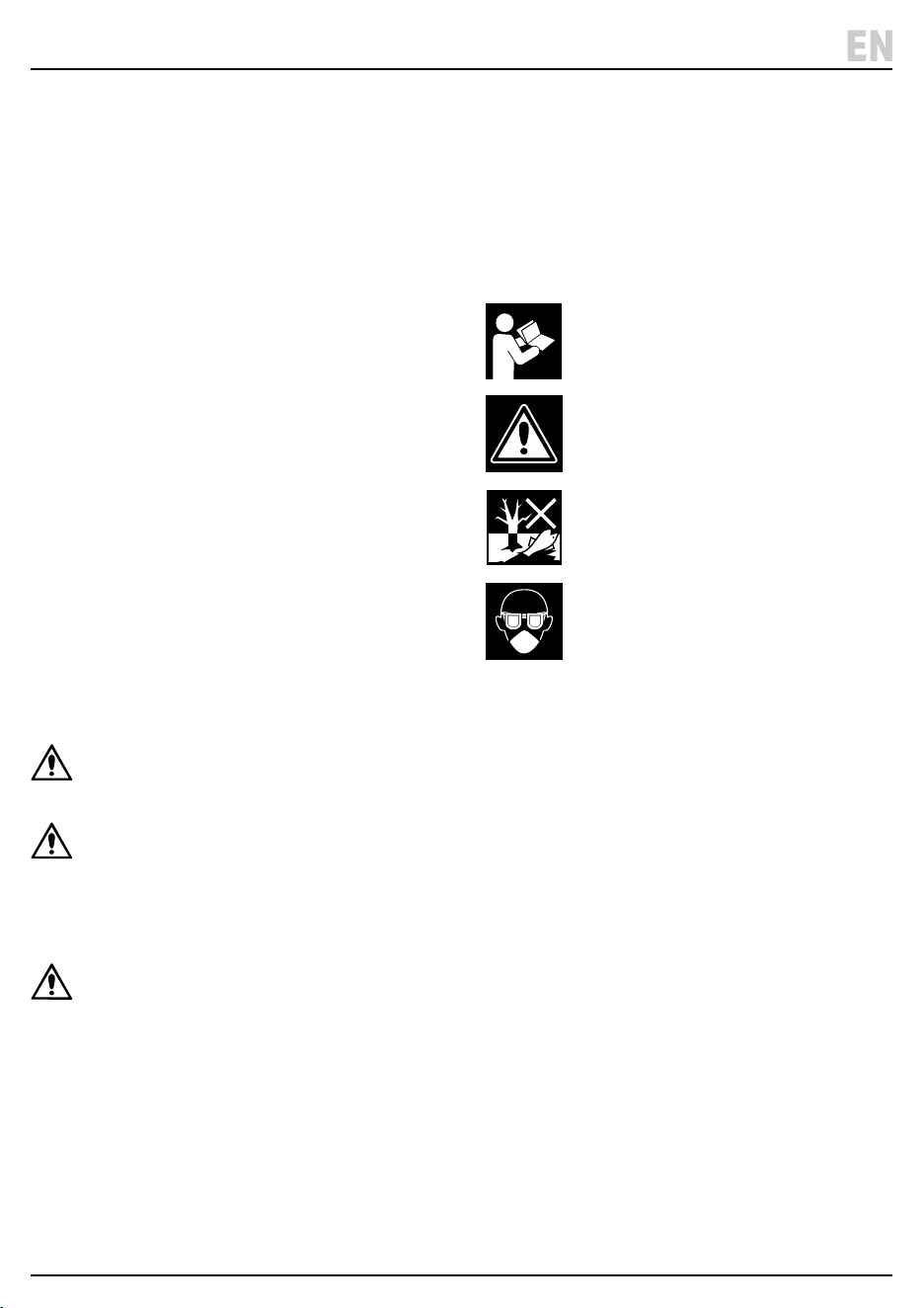
4.3 Explanation of symbols
– 5 –
EN
Read the instruction manual
Warning!
Do not abandon in the environment
Wear face mask and safety glasses
5. Identication and Unpacking
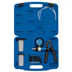
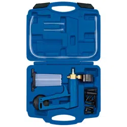
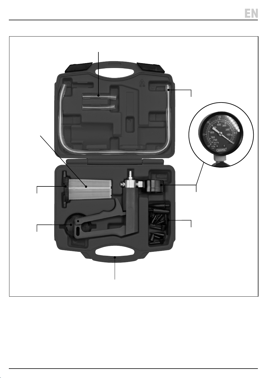
5.1 Product Overview
(1) Short Extension Tube X 2
(2) Long Extension Tube X 2
(3) Vacuum Gauge and Pump
(4) Hose and Nipple Adaptors
(5) Storage Case
(6) Transfer Cap
(7) Reservoir Cap
(8) 120ml Reservoir
– 6 –
EN
(1)
(2)
(4)
(3)
(5)
(6)
(7)
(8)
5. Identication and Unpacking
5.3 Packaging
Keep the product packaging for the duration of the
warranty period for reference should the product need to
be returned for repair.
WARNING!Keeppackagingmaterialsoutofreachof
children.Disposeofpackagingcorrectlyand
responsiblyandinaccordancewithlocalregulations.
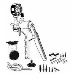
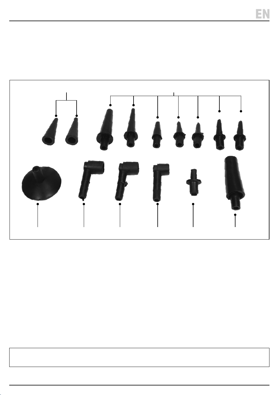
(A) 2 x Hose End Cones
(B) 7 X Tapered Hose Adaptors
(C) 1 X Large Tapered Hose Adaptor
(D) 1 X Stepped Adaptor
(E) 3 X Bleed Nipple Adaptors
E1. 1 X Large
E2. 1 X Medium
E3. 1 X Small
(F) 32mm Suction Cup
Please visit drapertools.com for our full range of accessories and consumables.
– 7 –
EN
5.2 What’s in the Box?
Carefully remove the product from the packaging and
examine it for any signs of damage that may have
occurred during shipment.
Before assembling the product, lay the contents out and
check them against the parts shown below. If any part is
damaged or missing, do not attempt to use the product.
Please contact the Draper Helpline; contact details can
be found at the back of this manual.
(A) (B)
(D)(E3)(E2)(E1)(F)
(C)
6. Operations
Important: Before preparing or adjusting this product,
read and understand all the safety instructions listed in
this manual.
ALWAYS refer to the manufacturer’s service manual to
ensure the correct testing procedures and specications
are followed. It is recommended that additional tests
such as compression tests, cylinder leakage tests,
ignition timing checks are carried out to conrm the
vacuum gauge readings.
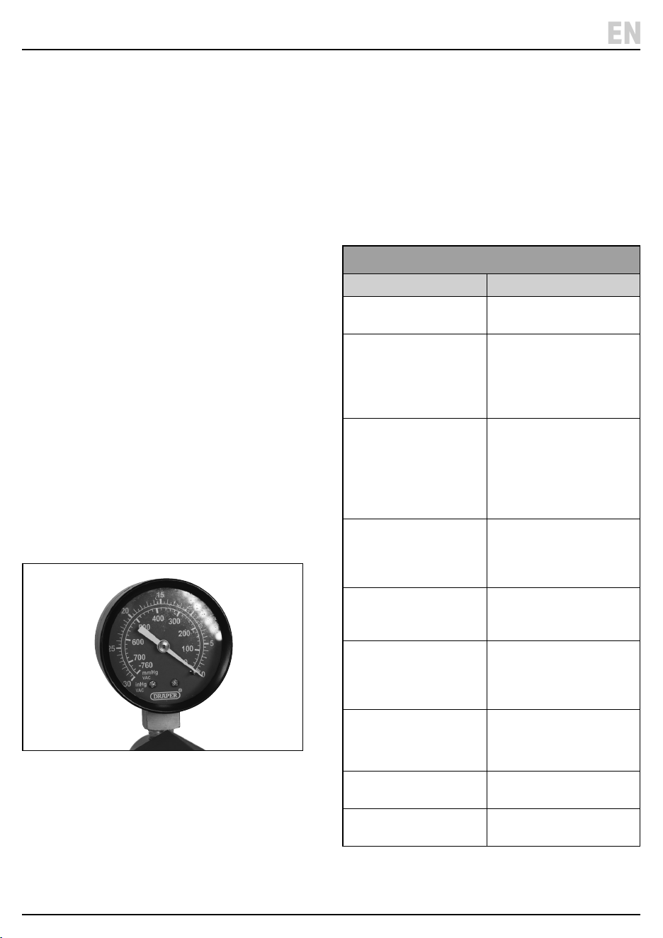
6.1 Analysing Engine Mechanical
Conditions Using Manifold Readings
(Refer to the diagnostic chart for examples of readings
that may be observed).
• Important Notes:
− The action of the needle on the gauge during
testing is more important to note rather than the
actual reading.
− Engine types will run with dierent manifold
vacuum pressures, depending on camshaft
prole, valve overlap and timing. For reference the
needle reading should be steady and between 16
to 21inHg.
− Manifold vacuum is also aected by altitude and it
will drop approximately 1inHg for every 1000feet
above sea level so this should also be taking into
consideration when assessing the readings.
1 Fig.
6.2 Basic Diagnostic Test
1. Run the engine until the normal operating
temperature is reached. Then switch o the engine.
2. Connect the vacuum gauge to a port directly on the
manifold or on the carburettor/throttle body below
the throttle buttery.
3. Start the engine and allow to idle, observe the gauge
reading as shown in the diagnostic testing.
– 8 –
EN
DiagnosticTesting
GaugeReading Cause
16 – 21inHg
Needle Steady
Normal
When throttle opened and
released, needle drops to
below 5inHg and then up to
25inHg. Then settles back
to original reading.
Normal
Steady but extremely low. Leaking intake manifold
system.
Faulty manifold or carburettor
base gasket.
Split vacuum hose.
EGR valve seized.
Steady but low. Retarded ignition timing.
Conrm using timing light
and reset to manufacturer’s
specication.
Slightly low and slowly
uctuating.
Over lean or rich mixture.
Check and reset as per
manufacturer’s specications.
Fluctuating between normal
and low readings.
Blown head gasket between 2
adjacent cylinders.
Carry out cylinder leakage
test.
Slightly lower than normal
even when throttle is
opened and released.
Worn piston rings.
Carry out compression test.
Regular drop between
normal and low reading.
Burnt Valve.
Normal until drops when
revs held at 3000rpm.
Restriction in exhaust system.

6. Operations
6.3 Ignition System Vacuum Advance
On standard points and some electronic ignition systems
there are two types of advance methods used, both of
which must function correctly to obtain maximum
performance and fuel economy.
• Mechanical/Centrifugal(Weightslocatedinthe
baseofthedistributor)- the weights move outwards
advancing the ignition timing as the engine RPM
increases. This is tested by disabling the system by
removing the vacuum advance line. Then with a
timing light connected, raise the engine RPM,
checking that the timing advances in accordance with
the manufacturer’s specication.
• VacuumAdvance(Engineloadsensedviamanifold
vacuum) - A vacuum diaphragm is mounted onto the
distributor and connected to a rotating internal base
plate which advances or retards timing as required to
suit varying engine loads.
a. To test this system for correct operation, connect a
timing light, raise the engine RPM and check the
timing advance against the manufacturer’s
specication. If the vacuum advance is not
operating, remove the vacuum line from the
distributor advance mechanism. Connect the
vacuum tester and create a 5-10inHg vacuum,
monitoring the timing at the same time. If a timing
advance is noted this conrms that the vacuum
diaphragm and mechanical links are in order and
that the fault is a vacuum supply.
b. To conrm this, connect the vacuum tester to the
vacuum supply line and check the gauge reading.
No vacuum should be noted at idle but when the
engine RPM is increased a vacuum increase should
be observed. If this does not occur, trace the
vacuum line back checking for restrictions and
breaks.
– 9 –
EN

7. Fuel Systems Testing
The vacuum tester can be used to evaluate the condition
of a mechanical fuel pump by testing the vacuum that it
is able to create.
• Locate and remove the suction line from the pump.
Connect the vacuum tester to the suction port of the
pump, start and run the engine at idle.
• The vacuum reading observed will vary depending on
the make and model being tested but as a general rule
approximately 15inHg of vacuum should be created.
This should also be held for approximately 1 minute
after the engine shuts down. If this vacuum reading is
not achieved or the vacuum drops o immediately
with the engine shut down, the fuel pump requires
either an overhaul or replacement.
7.1 Carburettor Testing
The vacuum test kit allows quick and accurate testing of
many dierent types of vacuum control systems used on
carburettors. Examples of tests that can be carried out;
• TestingaChokeBreakDiaphragm.
− With the engine o and at normal operating
temperature, disconnect the vacuum line to the
diaphragm module. Connect the vacuum tester
and apply approximately 15inHg of vacuum
and wait for 30 seconds.
− No drop in gauge reading should be observed.
With the vacuum still applied ensure that the
choke buttery is pulled to the fully open position.
• TestingVacuumOperatedCarburettorSecondary
Barrel.
− With the engine o and at normal operating
temperature, remove the vacuum line from the
secondary diaphragm module. Connect the
vacuum tester, hold the throttle and secondary air
valve aps open.
− Operate the hand pump whilst observing whether
the secondary throttle buttery opens freely.
7.2 Fuel Injection Pressure
Regulator Testing
Multi-point fuel injection rail pressure varies to suit
changing engine loads and fuel delivery requirements.
This is done using a vacuum operated regulator which is
connected to the engine manifold vacuum to sense the
varying loads.
a. To test the fuel rail pressure, attach a gauge to the
rail, then the engine loads must be created to vary
the engine manifold vacuum.
b. Remove and block o the vacuum supply line to
the pressure regulator.
c. Then connect and operate the vacuum pump to
simulate vacuum pressures in accordance with the
manufacturer’s specication. Note: any variation in
fuel pressure reading.
7.3 Emission Control Exhaust Gas
Recirculation Valve (EGR)
• Start the engine and run at idle until normal operating
temperature is reached. Remove the vacuum line from
the EGR valve and attach the vacuum test kit.
• Operate the hand pump to apply approximately
15inHg of vacuum. If the EGR valve is working
correctly the engine idle will become rough. If the idle
remains unchanged the valve is possibly seized in the
closed position. If the vacuum is not held, the
diaphragm in the valve has failed.
7.4 One-Way Valve Testing
Many vacuum operated circuits use in-line one way
valves to apply vacuum in one direction only.
• To test the function of the valve remove it from the
circuit. Attach the vacuum tester and operate pump to
apply vacuum. The valve should only hold vacuum in
one direction.
– 10 –
EN

7. Fuel Systems Testing
7.5 Electrically Operated Vacuum
Solenoid Testing
• Electrically operated vacuum solenoids are commonly
used in control circuits for air conditioning/ventilation
systems, emission control systems and idle step-up
systems.
1. Locate the solenoid to be tested and remove the line
that goes to the component.
2. Connect the vacuum tester to the solenoid port and
start the engine. With the system turned o the
gauge reading should be ‘0’.
3. Turn the system to the ‘on’ position and the gauge
reading should be equal to the manifold vacuum. If no
reading on the gauge, remove the vacuum supply line
and test for manifold vacuum at this point. If the
vacuum does exist this indicates that the solenoid is
faulty, or it is not receiving a ‘switch on’ voltage (use a
multimeter to test this). If no vacuum exists trace the
supply line back to the vacuum source checking for
kinks and breaks.
7.6 Thermal Vacuum Switch Testing
• There are many vacuum controlled circuits that must
only operate when the engine reaches normal
operating temperature. This is done using thermal
switches that remain in an ‘o’ position until a given
temperature is reached.
1. To test this type of switch, remove the vacuum supply
line coming from the manifold to the switch and test
the manifold vacuum.
2. If this vacuum is correct ret the supply line to the
thermal switch and remove the opposing line from
the switch.
3. Attach the vacuum tester to the port and start the
engine. With a cold engine no reading should be
noted. When the engine reaches normal operating
temperature a manifold vacuum reading should be
noted.
7.7 Vacuum Operated Heater Tap Testing
Climate control ventilation systems commonly use
vacuum operated taps to control the heating modes and
to turn the heater tap ‘on’.
1. To test, remove the supply line from the tap vacuum
module and connect the vacuum tester.
2. With the engine at normal operating temperature
locate the heater return hose. With the heater tap
in the ‘o’ position, this hose should be cold.
3. Operate the vacuum pump to open the tap. The
gauge reading must hold steady. If the tap is working
the return hose will begin to heat. If the hose does not
begin to heat, this indicates that the tap is faulty.
7.8 Automatic Transmission Vacuum
Operated Modulator Valves Testing
• Automatic transmissions are normally equipped with
a vacuum operated modulator valve in order for the
automatic transmission to detect engine loads and
adjust shift points to suit.
• The vacuum tester can test both whether the
modulation valve diaphragm is serviceable and to
simulate varying engine loads so modulator pressure
readings can be recorded.
1. Totestthemodulatorvalvediaphragm - remove the
vacuum supply line from the valve and attach the
vacuum tester. Operate the vacuum pump until
approximately 15inHg is achieved and monitor the
gauge reading for approximately 30 seconds. No
vacuum drop should be noted.
2. Tocheckmodulatorpressurereadings - attach a
pressure gauge to the appropriate port on the
transmission. Remove the vacuum supply line from
the modulator and attach the vacuum tester. Start
and run the engine and apply vacuum pressures.
Monitor readings and conrm that they conform with
the manufacturer’s specications.
– 11 –
EN

8. Braking Systems
8.1 Brake Servo Diaphragm Testing
1. Remove the vacuum supply line from the brake servo
tting.
2. Attach the vacuum tester to the vacuum supply port
on the servo. Operate the pump to create
approximately 15inHg of vacuum and wait for 30
seconds. No drop in the vacuum reading should be
observed. If the vacuum drops this indicates that the
brake servo diaphragm is faulty. In this case the servo
should be removed for overhaul or replaced by an
authorised repairer.
8.2 Brake And Clutch Bleeding Procedure
WARNING!Familiariseyourselfwiththehazards
ofbrakeuid-readandfollowthe
manufacturer’sinstructionsonthecontainer.
• DO NOT touch the vehicle’s brake pedal whilst
bleeding the brakes.
• Ensure that the vacuum pump is connected to the
brake bleeder reservoir in accordance with the car
manufacturer’s recommendations. Failure to do so will
result in brake uid being drawn into the vacuum
pump.
• Refer to the specic vehicle manufacturer’s
instructions for brake bleeding and wheel sequence
procedure before proceeding. If no specic
instructions from the vehicle manufacturer exist,
follow the instructions detailed below:-
1. Remove the cap of the vehicle’s master brake uid
reservoir. If the uid level is not at maximum, top it up.
2. Attach the appropriate size bleeding adaptor (A) to (E)
to the bleed nipple on the brake calliper of the rst
wheel, normally farthest from the master brake uid
reservoir.
3. Operate the vacuum pump until approximately
21inHg vacuum is created.
4. Apply copper grease to the brake bleeding nipples
before and after the brake bleeding procedure to
reduce the possibility of seized or broken nipples
when the brakes are next bled.
5. Open the bleed nipple about a quarter of a turn. Allow
brake uid to be drawn until no air bubbles are visible
in the brake uid in the clear hose.
6. Tighten the bleed nipple and remove the adaptor
from the brake nipple.
7. Repeat the process as necessary.
− NOTE! Check the master brake uid reservoir
regularly to ensure that the level does not drop too
far, and top up as necessary.
− Empty bleeder container regularly and do not
allow container to overll as brake uid will be
drawn into vacuum pump.
WARNING!Whenbrakebleedingand/oruid
changingiscomplete,testtheactionofthe
brakepedaltoensurethatthebrakesare
workingbeforeattemptingtodrivethevehicle
ontheroadandtestthevehicleforsatisfactory
performanceofthebrakingsystem.
– 12 –
EN

• After use, clean and store in the storage case in a cool,
dry, childproof area.
10. Spares, Returns and Disposal
For spare parts, servicing, and repair and replacement
options, please contact the Draper Tools Product
Helpline for details of your nearest authorised agent.
Any servicing or repairs carried out by unauthorised
personnel or installation of spare parts not supplied by
Draper Tools will invalidate your warranty.
At the end of its working life, dispose of the product
responsibly and in line with local regulations. Recycle
where possible.
• Dispose of waste liquids in accordance with local
authority regulations.
11. Warranty
Draper Tools products are guaranteed for 12months to
be free from defective materials and workmanship. Full
details of the warranty period can be found on the Draper
Tools Website.
Should the tool develop a fault within the warranty
period, return the complete tool to the place of purchase
or contact Draper Tools directly. Proof of purchase must
be provided.
This warranty does not apply to any consumable parts or
normal wear and tear.
It also does not cover any damage caused by misuse,
careless or unsafe handling, modications, or repairs
carried out by any personnel other than an authorised
Draper Tools repair agent.
Please note that this guarantee is in addition to and does
not aect your statutory rights.
9. Maintenance
– 13 –
EN

Notes
– 14 –
EN

Notes
– 15 –
EN

© Published by Draper Tools Limited© Published by Draper Tools Limited
Delta International
Delta International BV
Oude Graaf 8
6002 NL
Weert
Netherlands
Contact Details
Draper Tools
Draper Tools Limited
Hursley Road
Chandler’s Ford
Eastleigh
Hampshire
SO53 1YF
UK
Website: drapertools.com
Email: [email protected]
Product Helpline: +44 (0) 23 8049 4344
TelephoneSalesDesk: +44 (0) 23 8049 4333
GeneralEnquiries: +44 (0) 23 8026 6355
GeneralFax: +44 (0) 23 8026 0784
Please contact the Draper Tools Product Helpline for repair and servicing enquiries.