OWNER’S MANUAL
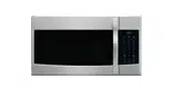
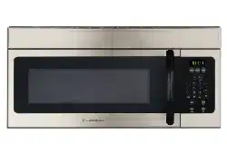
Microwave Oven
RMW1636SS
1. Read these instructions carefully before installing and operating the oven.
Keep them for further reference.
2. Record in the space below the “SERIAL NO.” found on the nameplate on your oven and
retain this information for future reference.
SERIAL NO.:

1
PRECAUTIONS TO AVOID POSSIBLE EXPOSURE TO
EXCESSIVE MICROWAVE ENERGY
(a) Do not attempt to operate this oven with the door open since open-door operation can result in
harmful exposure to microwave energy. It is important not to defeat or tamper with the safety
interlocks.
(b) Do not place any object between the oven front face and the door or allow soil or cleaner residue
to accumulate on sealing surfaces.
(c) Do not operate the oven if it is damaged. It is particularly important that the oven door close
properly and that there is no damage to the:
① Door (bent),
② Hinges and latches (broken or loosened),
③ Door seals and sealing surfaces.
(d) The oven should not be adjusted or repaired by anyone except properly qualified service
personnel.
CONTENT
PRECAUTIONS TO AVOID POSSIBLE EXPOSURE TO EXCESSIVE MICROWAVE ENERY ……………… 1
IMPORTANT SAFETY INSTRUCTIONS……………………………………………………………………………….2
UNPACKING INSTRUCTIONS………………………………………………………………………………………….4
GROUNDING INSTRUCTIONS…………………………………………………………………………………………4
INFORMATION YOU NEED TO KNOW………………………………………………………………………………..5
ABOUT YOUR OVEN……………………………………………………………………………………………….5
ABOUT FOOD………………………………………………………………………………………………………..6
ABOUT MICROWAVE COOKING………………………………………………………………………………….6
ABOUT SENSOR COOKING……………………………………………………………………………………….7
ABOUT SAFETY……………………………………………………………………………………………………..7
ABOUT UTENSILS AND COVERINGS……………………………………………………………………...…....7
ABOUT CHILDREN AND THE MICROWAVE ………………………………………………………………...…8
SPECIFICATIONS…………………………………………………………………………………………………….…..9
FEATURES DIAGRAM……………………………………………………………………………………………….…..9
CONTROL PANEL FEATURES……………………………………………………………………………………..…10
BASIC CONTROLS……………………………………………………………………………………………………...11
TO SET CLOCK………………………………………………………………………………………………….....11
TIME COOKING………………………………………………………………………………………………….…11
LIGHT CONTROL ..................................................................................................................................... 11
VENT FAN CONTROL .............................................................................................................................. 11
TURNTABLE ON/OFF .............................................................................................................................. 12
STOP/CLEAR ........................................................................................................................................... 12
SPECIAL FEATURES…………………………………………………………………………………………………...12
COMPU COOK ......................................................................................................................................... 12
COMPU DEFROST .................................................................................................................................. 13
MANUAL DEFROST ................................................................................................................................. 14
OTHER CONVENIENT FEATURES………………………..………………………………………………………....14
MINUTE PLUS/EXPRESS ........................................................................................................................ 14
TOUCH ON ............................................................................................................................................... 14
REHEAT ................................................................................................................................................... 14
KITCHEN TIMER ...................................................................................................................................... 14
CUSTOM HELP ........................................................................................................................................ 15
CLEAR AND CARE…………………………………………………………………………………………………...…15

2
IMPORTANT SAFETY INSTRUCTIONS
When using electrical appliances, basic safety
precautions should be followed, including the
following:
WARNING - To reduce the risk of burns,
electric shock, fire, injury to persons or
exposure to excessive microwave energy:
1. Read all instructions before using the
appliance.
2. Read and follow the specific
"PRECAUTIONS TO AVOID POSSIBLE
EXPOSURE TO EXCESSIVE
MICROWAVE ENERGY" on page 1.
3. This appliance must be grounded.
Connect only to properly grounded outlet.
See "GROUNDING INSTRUCTIONS” on
page 4.
4. Install or locate this appliance only in
accordance with the provided installation
instruction.
5. Some products such as whole eggs and
sealed containers -for example, closed
glass jars- are able to explode and should
not be heated in this oven.
6. Use this appliance only for its intended use
as described in this manual. Do not use
corrosive chemicals or vapors in this
appliance. This type of oven is specifically
designed to heat, cook, or dry food. It is
not designed for industrial or laboratory
use.
7. As with any appliance, close supervision is
necessary when used by children.
8. To reduce the risk of fire in the oven cavity:
a. Do not overcook food. Carefully attend
appliance when paper, plastic, or other
combustible materials are placed
inside the oven to facilitate cooking.
b. Remove wire twist-ties from paper or
plastic bags before placing bag in
oven.
c. If materials inside the oven ignite, keep
oven door closed, turn oven off, and
disconnect the power cord or shut off
power at the fuse or circuit breaker
panel.
9. Do not use the cavity for storage purposes.
Do not leave paper products, cooking
utensils or food in the cavity when not in
use.
10. Liquids, such as water, coffee, or tea are
able to be overheated beyond the boiling
point without appearing to be boiling due to
surface tension of the liquid. Visible
bubbling or boiling when the container is
removed from the microwave oven is not
always present. THIS COULD RESULT IN
VERY HOT LIQUIDS SUDDENLY
BOILING OVER WHEN A SPOON OR
OTHER UTENSIL IS INSERTED INTO
THE LIQUID. To reduce the risk of injury to
person:
11. Do not overheat the liquid.
12. Stir the liquid both before and halfway
through heating it.
13. Do not use straight-sided containers with
narrow necks.
14. After heating, allow the container to stand
in the microwave oven for a short time
before removing the container.
15. Use extreme care when inserting a spoon
or other utensil into the container.
16. Do not heat oil or fat for deep-frying. It is
difficult to control the temperature of oil in
microwave oven.
17. Pierce foods with heavy skins such as
potatoes, whole squash, apples and
chestnuts before cooking.
18. The contents of feeding bottles and baby
jars should be stirred or shaken and the
temperature should be checked before
serving in order to avoid burns.
19. Cooking utensils may become hot
because of heat transferred from the
heated food. Potholders may be needed to
handle the utensil.
20. Do not cover or block any openings on the
appliance.
21. Do not store or use this appliance outdoors.
Do not use this product near water, for
example, near a kitchen sink, in a wet
basement, near a swimming pool, or
similar locations.

3
22.
Do not operate this appliance if it has a
damaged cord or a plug, if it is not working
properly or if it has been damaged or
dropped.
23. Do not immerse cord or plug in water.
24. Keep cord away from heated surface.
25. Do not let cord hang over edge of table or
counter.
26. Use only thermometers, which are
specifically designed for use in microwave
ovens.
27. Do not operate any heating or cooking
appliance beneath this appliance.
28. Be certain the glass tray and roller rings
are in place when you operate the oven.
29. This appliance should be serviced only by
qualified service personnel. Contact
nearest authorized service facility for
examination, repair, or adjustment.
30. When cleaning surfaces of door and oven
that comes together on closing the door,
use only mild, nonabrasive soaps, or
detergents applied with a sponge or soft
cloth.

4
UNPACKING INSTRUCTIONS
Unpacking and Examining Your Oven
Carefully remove oven from carton. SAVE
THE CARTON AS IT MAY MAKE
INSTALLATION EASIER.
Remove:
1. All packing materials from inside the
oven cavity; however, DO NOT
REMOVE THE WAVEGUIDE COVER,
which is located on the ceiling in the
oven cavity. Check to see that there
are Installation Instructions, Wall
Template, Top Cabinet Template, bag
of Installation Hardware, Charcoal
Filter and Exhaust Damper Assembly.
Read enclosures and SAVE the
Owner’s Instructions.
2. The feature sticker from the outside of
the door, if there is one.
Check the oven for any damage, such as
misaligned or bent door, damaged door
seals and sealing surfaces, broken or loose
door hinges and latches and dents inside
the cavity or on the door. If there is any
damage, do not operate the oven and
contact your dealer.
See Installation Instruction for more details.
GROUNDING INSTRUCTIONS
This appliance must be grounded. In the
event of an electrical short circuit,
grounding reduces the risk of electric
shock by providing an escape wire for the
electric current. This appliance is equipped
with a cord having a grounding wire with a
grounding plug. The plug must be plugged
into an outlet that is properly installed and
grounded.
WARNING--- Improper use of the
grounding plug can result in a risk of
electric shock. Consult a qualified
electrician or serviceman if the grounding
instructions are not completely understood
or if doubt exists as to whether the
appliance is properly grounded
ELECTRICAL REQUIREMENTS
The electrical requirements are a 120 volt
60 Hz, AC only, 20 amp. It is
recommended that a separate circuit
serving only the oven be provided. The
oven is equipped with a 3-prong grounding
plug. It must be plugged into a wall
receptacle that is properly installed and
grounded.
Power Supply Cord
1. A short power supply cord is provided
to reduce the risks resulting from becoming
entangled in or tripping over a longer cord.
2. Longer cord sets or extension cords are
available and may be used if care is
exercised in their use.
3. If long cord or extension cord is used:
a) The marked electrical rating of the cord
set or extension cord should be at least as
great as the electrical rating of the
appliance.
b) The extension cord must be a
grounding-type 3-wire cord, and The longer
cord should be arranged so that it will not
drape over the counter top or table top
where it can be pulled on by children or
tripped over unintentionally.
Notes:
If you have any questions about the
grounding or electrical instructions, consult a
qualified electrician or service person.
Neither RCA nor the dealer can accept any
liability for damage to the oven or personal
injury resulting from failure to observe the
electrical connection procedures.
RADIO OR TV INTERFERENCE
Should there be any interference caused by
the microwave oven to your radio or TV,
check that the microwave oven is on a
different circuit, relocate the radio or TV as
far away from the oven as feasible or check
position and signal of receiving antenna.
5
INFORMATION YOU NEED TO KNOW
ABOUT YOUR OVEN
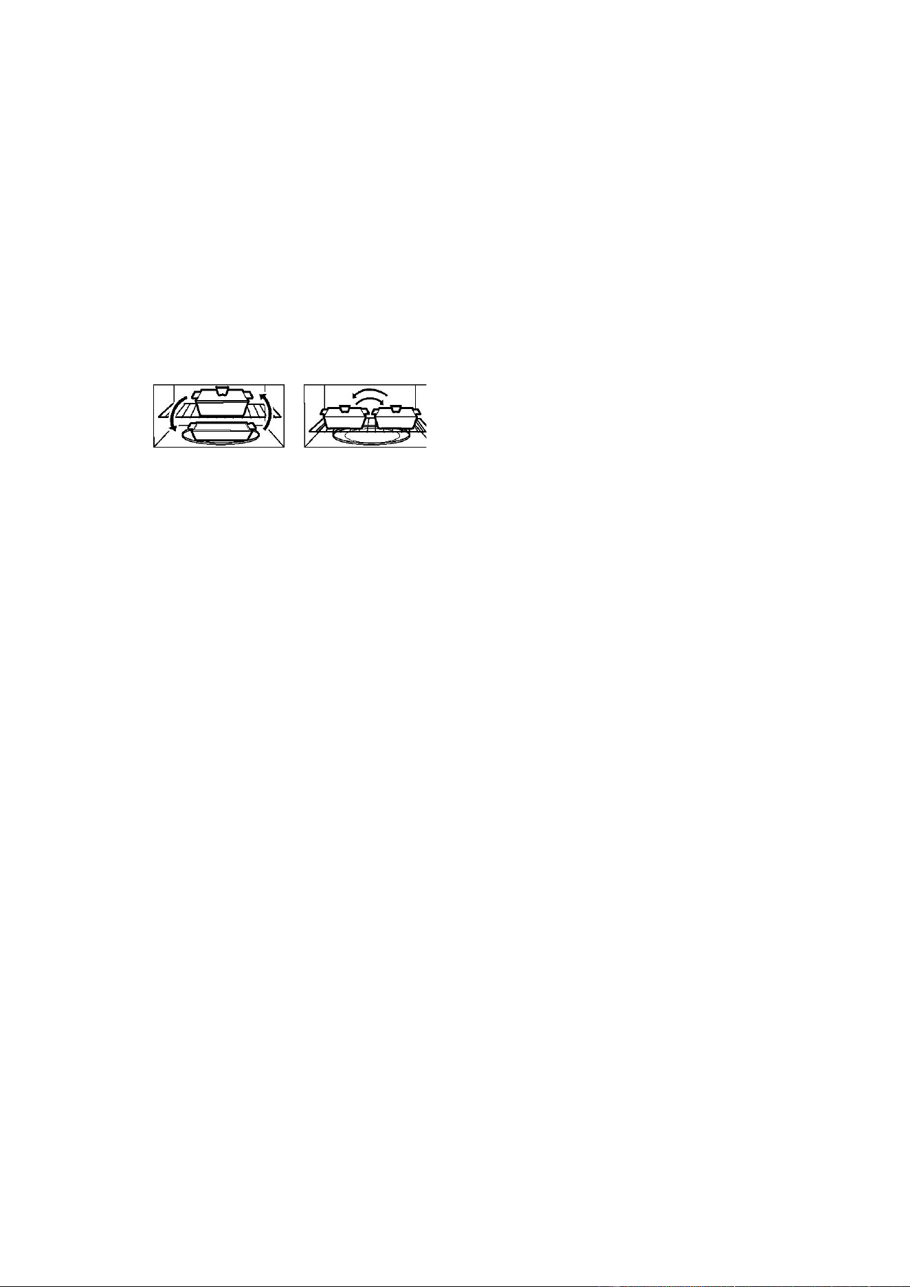
NEVER
use the oven without the turntable
and support nor turn the turntable over so
that a large dish could be placed in the
oven. The turntable will turn both clockwise
and anticlockwise.
The shelf gives you the option to reheat
more than one dish of food at the same
time. To reheat on 2 levels:
·Switch places after ½ the time.
·Make sure the shelf is positioned properly
inside the microwave to prevent damage to
the oven from arcing.
·Do not use a microwave browning dish on
the shelf. The shelf could overheat.
·Do not use the oven with the shelf on the
microwave floor. This could damage the
microwave.
·Use pot holders when handling the shelf-it
may be hot.
·Do not use the shelf when cooking popcorn.
ALWAYS have food in the oven when it is
on to absorb the microwave energy.
When using the oven at power levels below
100%, you may hear the magnetron cycling
on and off.
Condensation is a normal part of microwave
cooking. Room humidity and the moisture in
food will influence the amount of moisture
that condenses in the oven. Generally,
covered foods will not cause as much
condensation as uncovered ones.
Ventilation openings must not be blocked.
In using recipes or package directions,
check food a minute or two before the
minimum time and add time accordingly.

6
ABOUT FOOD
FOOD DO DON’T
Eggs,
sausages,
fruits &
vegetable
· Puncture egg yolks before cooking to
prevent “explosion”.
·Pierce skins of potatoes, apples, squash, hot
dogs and sausages so that steam escapes.
·Cook egg in shells.
·Reheat whole eggs.
Popcorn
· Use specially bagged popcorn for the
microwave oven.
·Listen while popping corn for the popping to
slow to 1 or 2 seconds or use special
Popcorn pad.
·
Pop popcorn in regular brown bags
or
glass bowls.
·Exceed maximum time on popcorn
package.
Baby food
·Transfer baby food to small dish and heat
carefully, stirring often. Check temperature
before serving.
·Put nipples on bottles after heating and
shake thoroughly. “Wrist” test before
feeding.
·Heat disposable bottles.
·Heat bottles with nipples on.
·Heat baby food in original jars.
General
·Cut baked goods with filling after heating to
release steam and avoid burns.
·Stir liquids briskly before and after heating to
avoid “eruption”.
·Use deep bowl, when cooking liquids or
cereals, to prevent boilovers.
·Heat or cook in closed glass jars or
airtight containers.
·Can in the microwave as harmful
bacteria may not be destroyed.
·Deep fat fry.
·Dry wood, gourds, herbs or wet
papers.
ABOUT MICROWAVE COOKING
Arrange food carefully. Place thickest areas
towards outside of dish.
·
Watch cooking time. Cook for the
shortest
amount of time indicated and
add more as needed. Food severely
overcooked can smoke or ignite.
·Cover foods while cooking. Check recipe or
cookbook for suggestions: paper towels,
wax paper, microwave plastic wrap or a
lid. Covers prevent spattering and help
foods to cook evenly.
·Shield with small flat pieces of aluminum
foil any thin areas of meat or poultry to
prevent overcooking before dense, thick
areas are cooked thoroughly.
·Stir foods from outside to center of dish
once or twice during cooking, if possible.
·
Turn foods over once during microwaving to
speed
cooking of such foods as chicken
and hamburgers. Large items like roasts
must be turned over at least once.
·Rearrange foods such as meatballs
halfway through cooking both from top to
bottom and from the center of the dish to
the outside.
·Add standing time. Remove food from oven
and stir, if possible. Cover for standing
time that allows the food to finish cooking
without overcooking.
·Check for doneness. Look for signs
indicating that cooking temperatures
have
been reached.
Doneness signs include:
-Food steams throughout, not just at
edge.
-Center bottom of dish is very hot to the
touch.
-Poultry thigh joins move easily.
-Meat and poultry show no pinkness.
-Fish is opaque and flakes easily with a
fork.

7
ABOUT SENSOR COOKING
·The proper containers and covers are essential for best sensor cooking.
· Always use microwave-safe containers and cover them with lids or vented plastic wrap. Never use
tight sealing plastic containers — they can prevent steam from escaping and cause food to
overcook.
·Be sure the outside of the cooking containers and the inside of the microwave oven are dry before
placing food in the oven. Beads of moisture turning into steam can mislead the sensor.
·Do not use this feature twice in succession on the same food portion — it may result in severely
overcooked or burnt food.
ABOUT SAFETY
Check foods to see that they are cooked to the following recommended temperatures.
TEMP FOOD
160℉
...for fresh pork, ground meat, boneless white poultry, fish, seafood, egg dishes and
frozen prepared food.
165℉
…for leftover, ready-to-reheat refrigerated, and deli and carry-out “fresh” food.
170℉
…white meat of poultry.
180℉
…dark meat of poultry.
·To test for doneness, insert a meat thermometer in a thick or dense area away from fat of bone.
NEVER leave the thermometer in the food during cooking, unless it is approved for microwave
oven use.
·ALWAYS use potholders to prevent burns when handling utensils that are in contact with hot food.
Enough heat from the food can transfer through utensils to cause skin burns.
·Avoid steam burns by directing steam away from the face and hands. Slowly lift the farthest edge of
a dish’s covering and carefully open popcorn and oven cooking bags away from the face.
·Stay near the oven while it’s in use and check cooking progress frequently so that there is no
chance of overcooking food.
·NEVER use the cavity for storing cookbooks or other items.
·Select, store and handle food carefully to preserve its high quality and minimize the spread of food
borne bacteria.
·Keep waveguide cover clean. Food residue can cause arcing and/or fires.
·Use care when removing items from the oven so that utensil, your clothes or accessories do not
touch the safety door latches.
ABOUT UTENSILS AND COVERINGS
It is not necessary to buy all new cookware.
Many pieces already in your kitchen can be
used successfully in your new microwave oven.
Make sure the utensil does not touch the
interior walls during cooking.

8
Use these utensils for safe microwave
cooking and reheating
·glass ceramic
·heat-resistant glass
·microwave-safe plastics
·paper plates
·microwave-safe pottery, stoneware and
porcelain
·browning dish
These items can be used for short time
reheating of foods that have little fat or
sugar in them:
·wood, straw, wicker
DO NOT USE
·metal pans and bake ware
·dishes with metallic trim
·non-heat-resistant glass
·non-microwave-safe plastic
·recycled paper bags
·food storage bags
·metal twist-ties
Should you wish to check if a dish is safe for
microwaving, place the empty dish in the oven
and microwave on HIGH for 30 seconds. A dish
which becomes very hot should not be used.
The following coverings are ideal:
·Paper towels are good for covering foods for
reheating and absorbing fat while cooking
bacon.
·Wax paper can be used for cooking and
reheating.
·Plastic wrap that is specially marked for
microwave use can be used for cooking and
reheating. DO NOT allow plastic wrap to
touch food. Vent so steam can escape.
·Lids that are microwave-safe are a good
choice because heat is kept near the food
to hasten cooking.
·Oven cooking bags are good for large meats
or foods that need tenderizing. DO NOT
use metal twist ties. Remember to slit bag
so steam can escape.
How to use aluminum foil in your
microwave oven:
·Small flat pieces of aluminum foil placed
smoothly on the food can be used to shield
areas that are either defrosting or cooking
too quickly.
· Foil should not come closer than one inch to
any surface of the oven.
ACCESSORIES
There are many microwave accessories
available for purchase. Evaluate carefully
before you purchase so that they meet your
needs. A microwave-safe thermometer will
assist you in determining correct doneness and
assure you that foods have been cooked to
safe temperatures. RCA is not responsible for
any damage to the oven when accessories are
used.
ABOUT CHILDREN AND THE MICROWAVE
Children below the age of 7 should use the microwave oven with a supervising person very near to
them. Between the ages of 7 and 12, the supervising person should be in the same room.
The children must be able to reach the oven comfortably; if not, he/she should stand on a sturdy
stool.
At no time should anyone be allowed to lean or swing on the oven door.
Children should be taught all safety precautions; use potholders, remove coverings carefully and
pay special attention to packages that crisp food because they may be extra hot.
Don’t assume that because a child has mastered one cooking skill he/she can cook everything.
Children need to learn that the microwave oven is not a toy.
9
SPECIFICATIONS
Power Supply 120V AC 60Hz Single phase
Microwave
Power Consumption 1550W
Output Power 1000W
Frequency 2450MHz
Outside Dimensions 16
7
/
8
”(H)×29
7
/
8
”(W)×17
5
/
8
”(D)
Cavity Dimensions 10
3
/
16
”(H)×21
1
/
2
”(W)×14
13
/
16
”(D)
Oven Capacity 1.6 Cu.Ft.
Cooking Uniformity Turntable /Stirrer Fan System
Weight Approx. (net) 60.0lb / (gross) 68.8lb
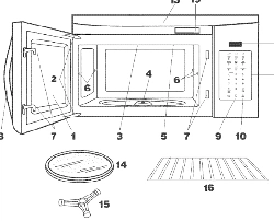
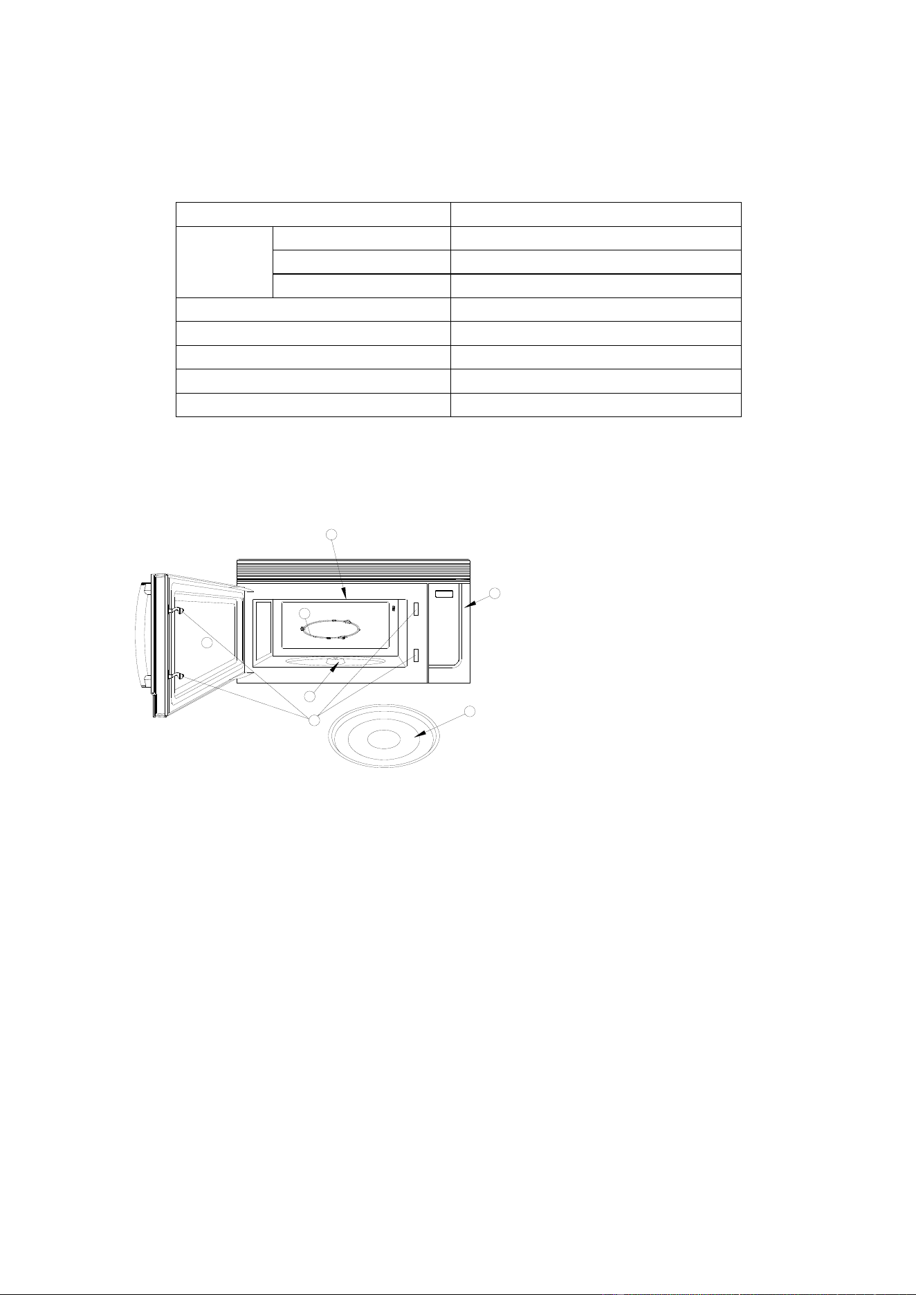
FEATURES DIAGRAM
1. Door Safety Lock System
2. Oven Window
3. Wave Guide
4. Roller Ring
5. Shaft
6. Control Panel
7. Glass Turntable
DO NOT REMOVE THE CARDBOARD OVEN AIR
VENT COVER THAT IS INSIDE THE MICROWAVE!
6
4
3
7
2
1
5
10
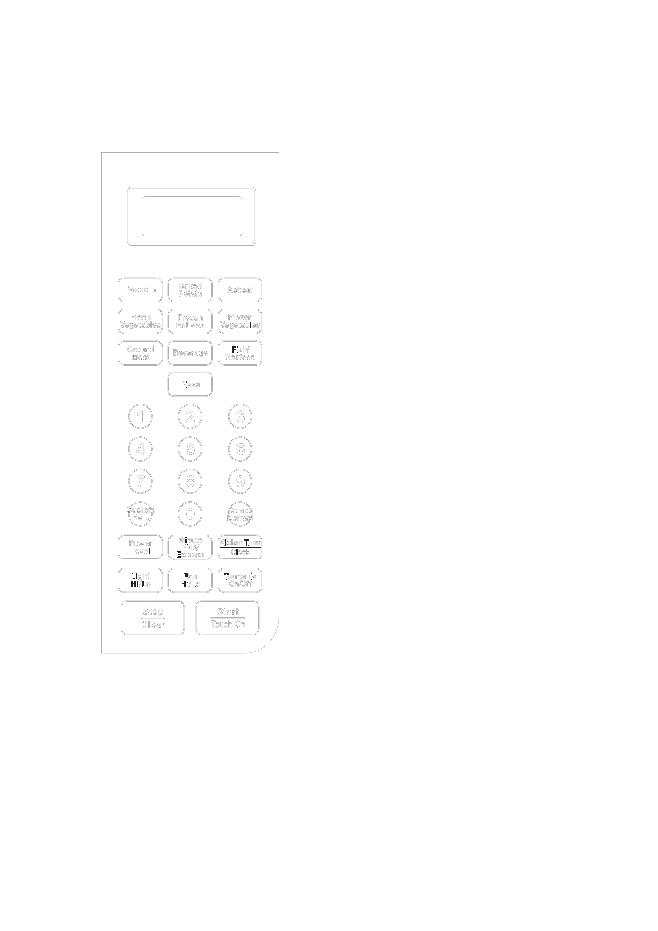
CONTROL PANEL FEATURES
DISPLAY SCREEN
Cooking time, Lock indicator, timer, defrost sign
and help information are displayed.
CUSTOM HELP
Information is available to help the user with
cooking.
COMPU DEFROST
Easy settings to defrost according to weight
entered.
POWRE LEVEL
Use to set cooking power level.
MINUTE PLUS/EXPRESS
Use to set express cooking time.
KITCHEN TIMER/CLOCK
Use to set the oven clock or set the timer.
LIGHT HI/LO
Press to set the controls of the light outside the
oven (light, dark and off mode).
FAN HI/LO
Fan motor control key. Press to select high, low or
off mode.
TURNTABLE ON/OFF
Touch to turn the turntable on or off.
STOP/CLEAR
Touch to stop the oven or reset the oven before
setting a program.
START/TOUCH ON
Touch to start the oven; also use to start the oven
quickly at full power.
The following pages contain more information for
the use of these features.
11
BASIC CONTROLS
Before operating your new microwave oven,
please read and understand this operation
manual completely.
SIGNALS DURING OVEN SETTINGS
ONE SIGNAL: Oven accepts the entry.
TWO SIGNALS: Oven does not accept the
entry, please check and try again.
TO SET THE CLOCK
This is a clock in 12- or 24- hour cycle.
Suppose you want to enter 8:08.
1. In standby mode, touch KITCHEN
TIMER/CLOCK pad once.
2. Touch START/TOUCH ON once,
“HR:12” is displayed. If you want to set
the clock in 24-hour cycle, touch
KITCHEN TIMER/CLOCK again,
“HR:24” will be displayed.
3. Press number pads 8, 0, and 8.
4. Touch START/TOUCH ON to confirm.
Note: If you happen to set a clock time in
exceed of the default range, touch
START/TOUCH ON, two beeps will sound
with “0:00” displayed, now you can enter
the correct clock time. During cooking, you
can press KITCHEN TIMER/CLOCK pad to
check the clock.
TIME COOKING
The longest cooking time is 99 minutes and
99 seconds. There are 6 power levels for
you to choose.
Please consult cookbook or recipes for
specific recommendations.
APPROXIMATE
PERCENTAGE
OF POWER
COMMON
WORDS FOR
POWER LEVELS
100%(P-100)
High
80%(P-80)
Medium High
60%(P-60)
Medium
40%(P-40)
Medium Low
20%(P-20)
Low/Defrost
0% (P -00)
Zero
Suppose you want to cook for 5 minutes at
80% power.
1.
Touch POWER LEVEL to select
cooking power P-80.
2. Use the number pads to enter cooking
time.
3. Touch START/TOUCH ON pad.
Note: You can check the power level
during cooking by pressing POWER
LEVEL.
LIGHT CONTROL
This feature is designed for the
convenience of doing things outside the
oven. To turn on the light at the bottom of
the oven, press LIGHT HI/LO:
Press the button Working Mode
Once Light
Twice Dark
3 times Off
VENT FAN CONTROL
Your oven can be used as a range hood.
When it is turned on, the fan motor starts
filtering out smoke, odors, and grease
generated from cooking.
Press FAN HI/LO:
Press the button Fan Speed
Once High
Twice Low
3 times Off
12
TURNTABLE ON/OFF
For most cooking, the turntable should be
on; however the turntable can be turned off
so that it does not rotate for extra large
dishes, such as the 13×9×2 glass utility
casserole. Put the casserole on the
turntable, press TURNTABLE ON/OFF
button to turn the turntable on or off.
Sometimes the turntable may become too
hot to touch. Be careful to touch the
turntable.
STOP/CLEAR
Touch the STOP/CLEAR pad to:
1. Clear previous setting.
2. Cancel Timer.
3. Stop the oven temporarily during
cooking.
4. Set CHILD LOCK
5. Cancel a program during cooking,
touch twice.
SPECIAL FEATURES
COMPU COOK
For foods shown in the following chart, it is
not necessary to program the time and the
cooking power. It is sufficient to indicate the
type of food that you want to cook as well as
the weight of this food.
For Popcorn, Beverage and Fish/Seafood,
you can press the food icon pad to select
weight or the amount.
Suppose you want to cook 3.0 oz. popcorn.
1. Touch POPCORN pad once.
2. Touch POPCORN pad again to select
weight.
3. Touch START/TOUCH ON pad
For Baked potato, Pizza, Fresh vegetables,
Frozen entrees, Frozen vegetables and
Ground meat, you can use the number
pads to enter the weight you needed.
Suppose you want to cook Baked potato (2
lb. 5oz.).
1. Touch BAKED POTATO pad once.
2. Touch 2 to enter 2 lb.
3. Touch START/TOUCH ON pad.
4. Touch 5 to enter 5oz.
5. Touch START/TOUCH ON pad.
COMPU COOK CHART
Food
Note
Popcorn (1.2oz / 3.0oz / 3.5oz)
1. For Popcorn and Fish/Seafood, you can
select weight or the amount by pressing
the food icon pad; for others, you should
use the number pads to enter the weight.
2. For Frozen entrees and Ground meat,
during cooking, the oven will pause to
remind you to turn food over for better
cooking effect.
3. For Beverage, the number shows on the
screen is not the weight but the number of
cup of beverage.
Baked potato (1oz ~ 3lb)
Pizza (1oz ~ 1lb. 12oz)
Fresh vegetables (1oz ~ 3lb)
Frozen entrees (1oz ~ 2lb.5oz)
Frozen vegetables (1oz ~ 3lb)
Ground meat (1oz - 6lb)
Beverage (1~6cups)
Fish/seafood (6~22oz)
Reheat (1oz ~ 2lb.5oz)

13
COMPU DEFROST
Compu Defrost automatically defrosts foods
from the following chart. Press COMPU
DEFROST, the display shows COMPU
DEFROST SELECT FOOD NUMBER SEE
LABLE CODE 1-6, then enter number 1~6 to
select.
Suppose you want to defrost ground meat
(2LB.5OZ.).
1. Touch COMPU DEFROST pad once,
2. Touch 1 for ground meat.
3. Touch START/TOUCH ON pad.
4. Enter weight by touching the number pad 2.
5. Touch START/TOUCH ON pad.
6. Enter weight by touching the number pad 5.
7. Touch START/TOUCH ON pad.
Suppose you want to defrost Soup.
1. Touch COMPU DEFROST pad once.
2. Touch 6 for Soup.
3. Touch START/TOUCH ON pad.
4. Enter number of cups by touching number
pads from 1 to 6.
5. Touch START/TOUCH ON pad.
COMPU DEFROST CHART
Number
pad/Food
Weight Range Procedure
1. Ground
meat
1oz.~3lb.
Remove any thawed pieces after each stage.
Let the meat remain covered for 5 to 10 minutes.
2. Steak
chops or
pork
1oz.~4lb.
After each stage, rearrange and if there are warm or thawed
portions, shield with small flat pieces of aluminum foil. Remove
any meat or fish that is almost defrosted. Let the meat remain
covered for 10 to 20 minutes.
3. Chicken
pieces or
poultry
1oz.~3lb.
After each stage, rearrange pieces or remove portions that
become warm or thawed. Let the meat remain covered for 10 to
20 minutes.
4. Fish or
seafood
1oz.~4lb.
After audible signal, stir if possible. Let the meat remain covered
for 5 to 10 minutes.
5. Roast 1oz.~4lb.
Start defrosting with fat side down. After each stage, turn roast
over and shield the warm portions with aluminum foil.
Let the meat remain covered for 30 to 60 minutes.
6. Soup
1~6 cups
(7 oz /cup)
After audible signal, stir if possible. Let the meat remain covered
for 5 to 10 minutes.
Note:
For soup, parameter on display is not weight but number of servings.
For some program, during cooking, the oven will pause and beep to remind you to open the
door and check its doneness and turn food over to obtain better cooking effect;
After the last stage, small sections may still be icy. Let stand to continue thawing. Do not
defrost until all ice crystals are thawed.
Use small smooth strips of aluminum foil to cover edges and thinner sections of the food.

14
MANUAL DEFROST
If the food that you want to defrost is not listed
on the COMPU DEFROST CHART or the food
weight is exceed the maximum weight
recommended, you need to defrost manually.
You can defrost any frozen food, either raw or
previously cooked, by using 20% microwave
power. Follow the steps under Time Cooking.
Always stop the oven periodically to remove or
separate the portions that are defrosted. If food
is not defrosted at the end of the estimated
defrosting time, program the oven in 1-minute
increments on 20% microwave power until
totally defrosted.
Please remember to place the food on a
microwave-safe dish not in a plastic container.
OTHER CONVENIENT FEATURES
MINUTE PLUS/EXPRESS
Minute Plus/Express allows you to cook at 100% by simply touching the MINUTE PLUS/EXPRESS
pad. You can also extend cooking time by touching the MINUTE PLUS/EXPRESS pad during
manual cooking to add 30 seconds each; the longest cooking time is 99 minutes 59 seconds. The
oven starts working at full power level immediately.
TOUCH ON
Touch On allows you to cook at 100% power by touching the START/TOUCH ON continuously.
Touch On is ideal for melting cheese, bringing milk to just below boiling etc.
Suppose you want to melt cheese on toast.
1. Continuously touch START/TOUCH ON pad. The cooking time will begin counting up.
2. When the cheese is melted to desired degree, remove finger from START/TOUCH ON pad. Oven
stops immediately.
REHEAT
Reheat function use 100% microwave power level to reheat the food based on the weight you
entered.
Suppose you want to reheat 2LB.5OZ. food.
1. Press REHEAT pad once.
2. Press number pad 2 for 2LB.
3. Press START/TOUCH ON pad once.
4. Press number pad 5 for 5OZ.
5. Press START/TOUCH ON pad once.
NOTE: The weight range is 1oz.-2lb.5oz.
KITCHEN TIMER
The longest time you can enter is 99 minutes and 99 seconds. Suppose you want to time a 3
minutes cooking.
1. In either cooking or standby mode, touch KITCHEN TIMER/CLOCK pad twice.
2. Use the number pads to enter time.
3. Touch START/TOUCH ON pad.
NOTE: When it reaches the end of the set time, the buzzer will beep to remind you.

15
CUSTOM HELP
CUSTOM HELP provides hints for 3 features which make it easy to use the oven because specific
instructions are provided in the Interactive Display.
1. WEIGHT HINT
Press CUSTOM HELP once, the screen will show you the weight range of compu defrost.
2. CLOCK HINT
If you are at a lost of how to set the clock time, press CUSTOM HELP once, steps in setting the
clock will be displayed one by one.
3. CHILD LOCK HINT
The child lock prevents unsupervised operation by children. The oven can be set so that the control
panel is deactivated or locked. Corresponding hints will be displayed if you press CUSTOM HELP
twice.
To set, touch and hold STOP/CLEAR for 3 seconds, a beep sounds and indicator lock is displayed.
To cancel, touch and hold STOP/CLEAR for 3 seconds.
4. SOUND ON/OFF
If you want to have the oven operate with no audible signals, press and hold CUSTOM HELP for 3
seconds, a beep sounds to indicate sound off.
To cancel and restore the audible signal, press and hold CUSTOM HELP for 3 seconds, a beep
sounds to indicate sound on.
Corresponding hints will be displayed if you press CUSTOM HELP for 3 times.
CLEAR AND CARE
Exterior
The outside surface is precoated steel and
plastic. Clean the outside with mild soap and
water; rinse and dry with a soft cloth. Do not
use any type of household or abrasive cleaner.
Door
Wipe the window on both sides with a damp
cloth to remove any spills or spatters. Metal
parts will be easier to maintain if wiped
frequently with a damp cloth. Avoid the use of
spray and other harsh cleaners as they may
stain, streak or dull the door surface.
Touch Control Panel
C
are should be taken in cleaning the touch
control panel. If the control panel becomes
soiled, open the oven door before cleaning.
Wipe the panel with a cloth dampened slightly
with water only. Dry with a soft cloth. Do not
scrub or use any sort of chemical cleaners.
Close door and touch STOP/CLEAR.
Interior
Cleaning is easy because little heat is
generated to the interior surfaces; therefore,
there is no baking and setting of spills or
spattering. To clean the interior surfaces, wipe
with a soft cloth and warm water. DO NOT USE
ABRASIVE OR HARSH CLEANERS OR
SCOURING PADS. For heavier soil, use
baking soda or a mild soap; rinse thoroughly
with hot water.
Waveguide Cover
The waveguide cover is located on the ceiling
in the oven cavity. It is made from mica so
requires special care. Keep the waveguide
cover clean to assure good oven performance.
Carefully wipe with a damp cloth any food
spatters from the surface of the cover
immediately after they occur. Built-up splashes
may overheat and cause smoke or possibly
16
catch fire. DO NOT REMOVE THE
WAVEGUIDE COVER.
Odor Removal
Occasionally, a cooking odor may remain in the
oven. To remove, combine 1 cup water, grated
peel and juice of 1 lemon and several whole
cloves in a 2-cup glass measuring cup. Boil for
several minutes using 100% power. Allow to
set in oven until cool. Wipe interior with a soft
cloth.
Turntable/Turntable Support
The turntable and turntable support can be
removed for easy cleaning. Wash them in mild,
sudsy water; for stubborn stains use a mild
cleanser and non-abrasive scouring sponge as
described above. They are also
dishwasher-proof. Use upper rack of
dishwasher. The turntable motor shaft is not
sealed, so excess water or spills should be
wiped up immediately.
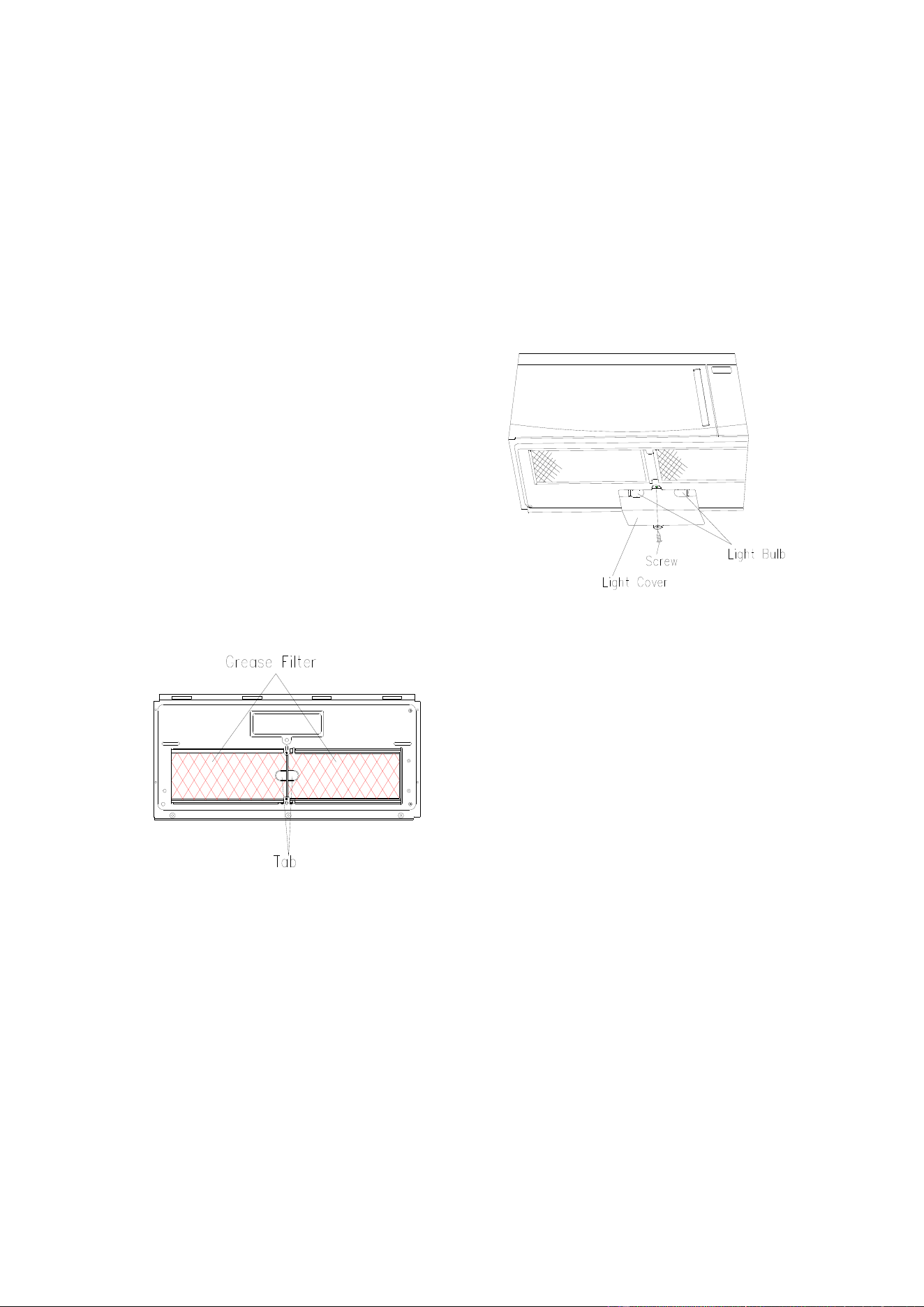
Grease Filters
Filters should be cleaned at least once a month.
Never operate the fan or oven without the filters
in place.
Pull down slightly on the tab toward the front of
the oven and remove the filter. Repeat for the
other filter.
Soak the filter in a sink or dish pan filled with
hot water and detergent. DO NOT use
ammonia or other alkali; they will react with the
filter material and darken it.
Agitate and scrub with a brush to remove
embedded dirt.
Rinse thoroughly and shake dry.
Replace by fitting the filter back into the
opening.
Light
1. To replace light bulbs, first disconnect power
to the oven at the circuit breaker panel or by
unplugging.
2. To release cover, remove the screw on the
light cover. (See illustration.)
3. DO NOT USE A BULB LARGER THAN 30
WATTS.
Close light cover and secure with screw
removed in step 2.
CAUTION: Light cover may become very hot.
Do not touch glass when light is on.
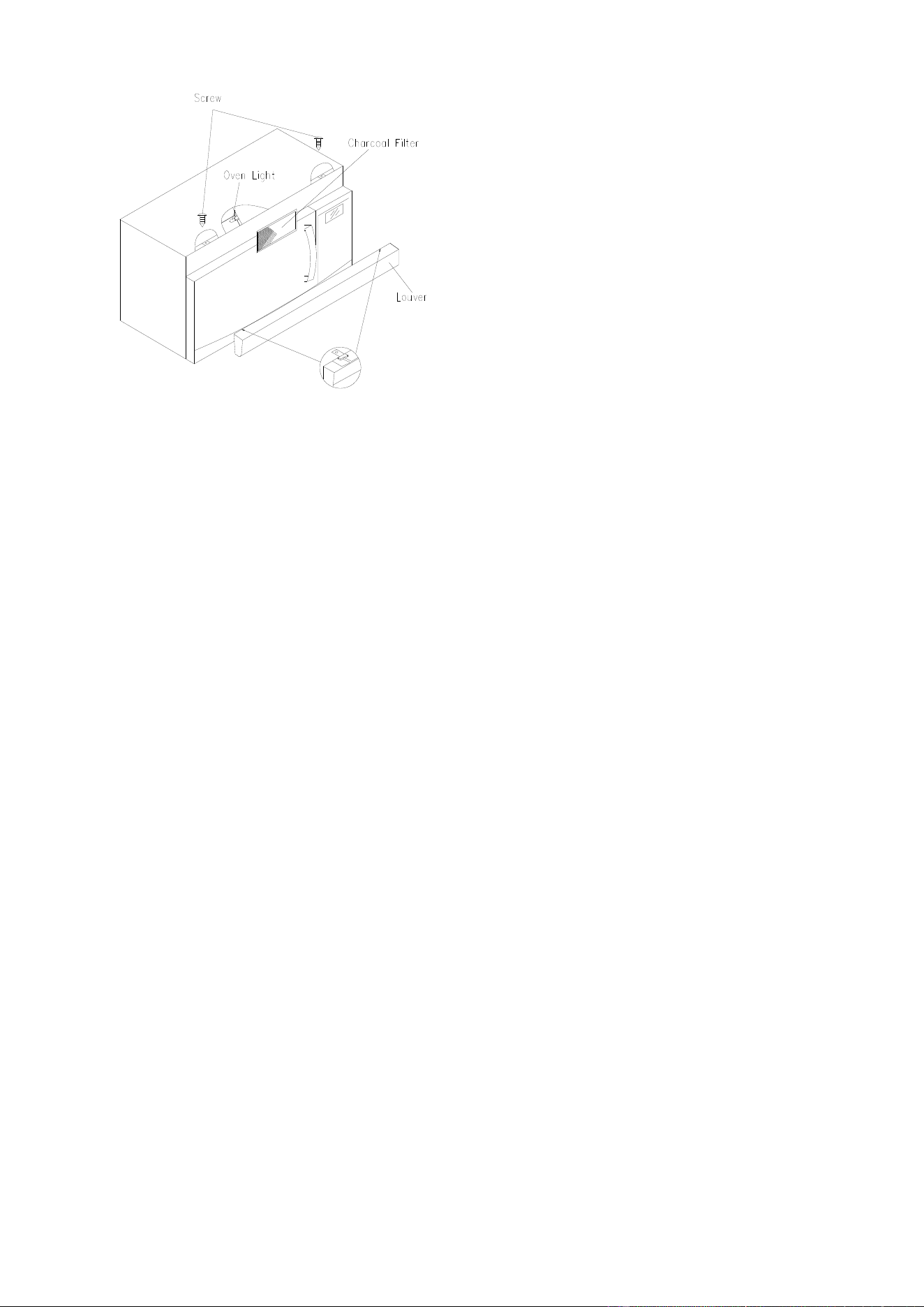
Charcoal Filter
Charcoal filter is used for nonvented,
recirculated installation. The filter should be
changed every 6 to 12 months depending on
use.
1. Disconnect power to the oven at the circuit
breaker panel or by unplugging.
2. Remove the louver mounting screw from the
top center of the louver and push down
carefully on the tab at each end of the louver
to disengage it. (See illustration.)
3. Pull the louver away from the unit.
4. Change the charcoal filter.
5. Carefully push the louver back into place and
replace the screw remove in step 2.
17
Oven Light
Remove the louver per instructions 1~3 above
and charcoal filter, if used.
1. Open light cover located behind filter
mounting by carefully pulling up on the front
edge.
2. DO NOT USE A BULB LARGER THAN 30
WATTS.
3. Replace the oven light cover by carefully
pushing into place. Replace the charcoal
filter, if used. Push the louver back into place
and replace the louver mounting screw.
Microwave Oven
RMW1636SS
Installation Intructions
1. Read these instructions carefully before installing and operating the oven.
Keep them for further reference.
2. Record in the space below the “SERIAL NO.” found on the nameplate on your oven and
retain this information for future reference.
SERIAL NO.:
Installation Instructions
2
CONTENTS
G
eneral information
Important Safety Instructions .....................3
Electrical Requirements ..............................3
Hood Exhaust ...........................................4, 5
Damage – Shipment/Installation .................6
Parts Included...............................................6
Tools You Will Need.....................................7
Mounting Space............................................7
S
tep-by-step installation guide
Placement of Mounting Plate ................8–10
Removing the Mounting Plate ................... 8
Finding the Wall Studs .............................. 8
Determining Wall Plate Location ............... 9
Aligning the Wall Plate ............................ 10
Installation Types .................................11–22
A
Outside Top Exhaust .............................. 12–15
Attach Mounting Plate to Wall ................. 12
Preparation of Top Cabinet ..................... 13
Chec
king for Proper Damper Operation...14
Mount the Microwave Oven..................... 14
Adjust the Exhaust Adaptor..................... 15
Connecting Ductwork .............................. 15
B
Outside Bac
k Exhaust............................. 16–19
Preparing Rear Wall for
Outside Back Exhaust. ............................ 16
.
Attach Mounting Plate to Wall ................. 17
Preparation of Top Cabinet ..................... 17
Adapting Microwave Blower for
Outside Back Exhaust ....................... 17, 18
Mount the Microwave Oven..................... 19
C
Recirculating ........................................... 20–22
Attach Mounting Plate to Wall ................. 20
Preparation of Top Cabinet ..................... 20
Mount the Microwave Oven............... 21, 22
Installing the Charcoal Filter .................... 22
Before You Use Your Microwave ..............23
Installation Instructions
3
IMPORTANT SAFETY INSTRUCTIONS
This produc
t requires a three-prong grounded outlet.
The installer must perform a ground continuity check
on the power outlet box before beginning the
installation to insure that the outlet box is properly
grounded. If not properly grounded, or if the outlet
box does not meet electrical requirements noted
(under ELECTRICAL REQUIREMENTS), a qualified
electrician should be employed to correct any
deficiencies.
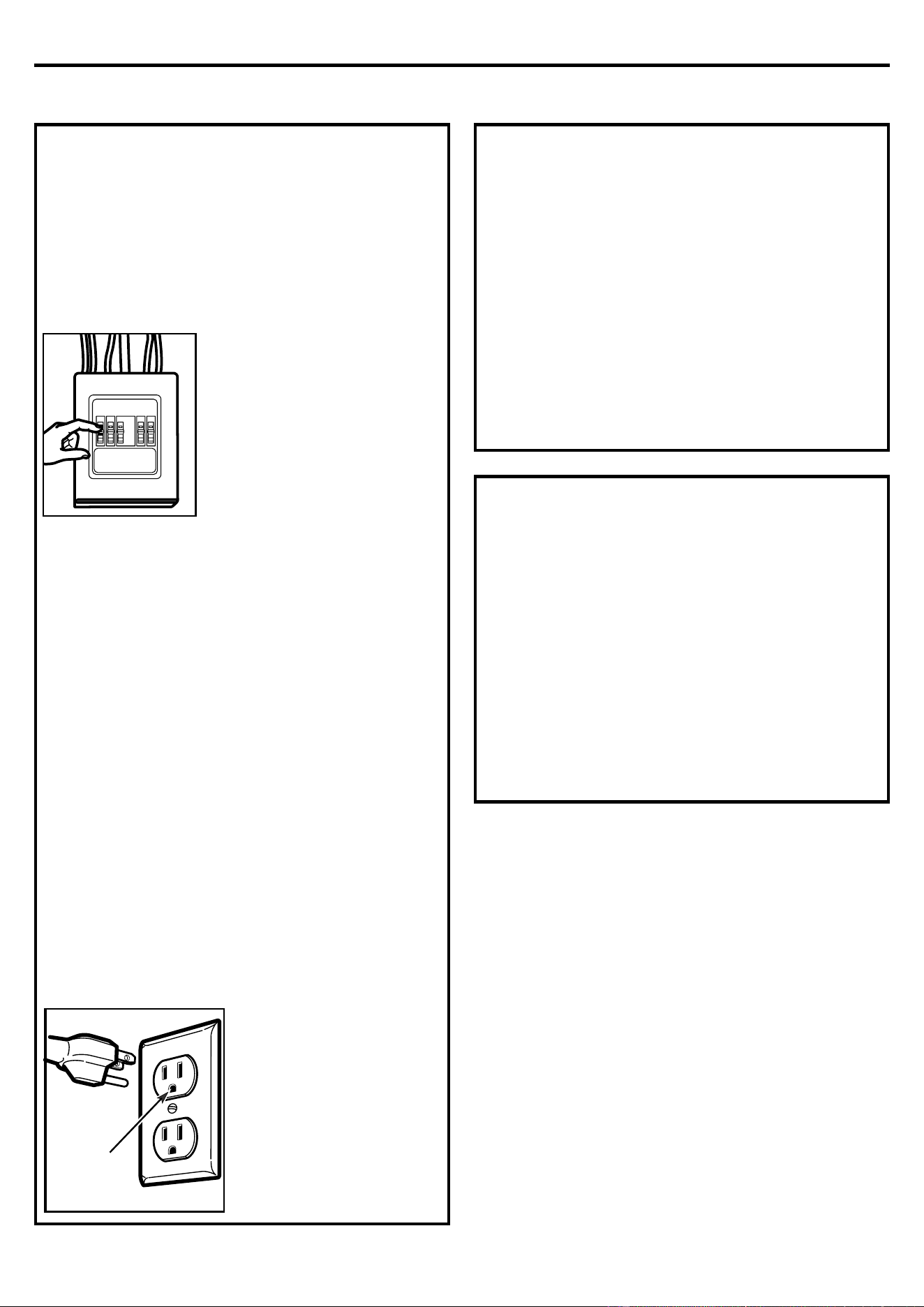
CAUTION: For personal
safety, remove house fuse or
open circuit breaker before
beginning installation to
avoid severe or fatal shock
injury.
CAUTION: For personal safety, the mounting
surface must be capable of supporting the
cabinet load, in addition to the added weight of
this 54 pound product, plus additional oven loads
of up to 50 pounds or a total weight of 104
pounds.
CAUTION: For personal safety, this product
cannot be installed in cabinet arrangements such
as an island or a peninsula. It must be mounted to
BOTH a top cabinet AND a wall.
NOTE: For easier installation and personal
safety, it is recommended that two people install
this product.
IMPORTANT–PLEASE READ CAREFULLY. FOR
PERSONAL SAFETY, THIS APPLIANCE MUST BE
PROPERLY GROUNDED TO AVOID SEVERE OR
FATAL SHOCK.
The power cord of this
appliance is equipped
with a three-prong
(grounding) plug which
mates with a standard
three-prong (grounding)
wall receptacle to
minimize the possibility
of electric shock hazard
from this appliance.
You should have the wall receptacle and circuit
checked by a qualified electrician to make sure
the receptacle is properly grounded.
Where a standard two-prong wall receptacle is
encountered, it is very important to have it
replaced with a properly grounded three-prong
wall receptacle, installed by a qualified
electrician.
DO NOT, UNDER ANY CIRCUMSTANCES, CUT,
DEFORM OR REMOVE ANY OF THE PRONGS
FROM THE POWER CORD. DO NOT USE WITH
AN EXTENSION CORD.
E
LECTRICAL REQUIREMENTS
P
roduct rating is 120 volts AC, 60 Hertz, 15 amps and
1.58 kilowatts. This product must be connected to a
supply circuit of the proper voltage and frequency.
Wire size must conform to the requirements of the
National Electrical Code or the prevailing local code
for this kilowatt rating. The power supply cord and
plug should be brought to a separate 20 ampere
branch circuit single grounded outlet. The outlet box
should be located in the cabinet above the
microwave oven. The outlet box and supply circuit
should be installed by a qualified electrician and
conform to the National Electrical Code or the
prevailing local code.
Insure pro
per
ground exists
before use
I
nsure proper
ground exists
before use
Installation Instructions
4
HOOD EXHAUST
NO
TE: Read these next two pages only if you plan to vent your exhaust to the outside. If you plan to
recirculate the air back into the room, proceed to page 6.
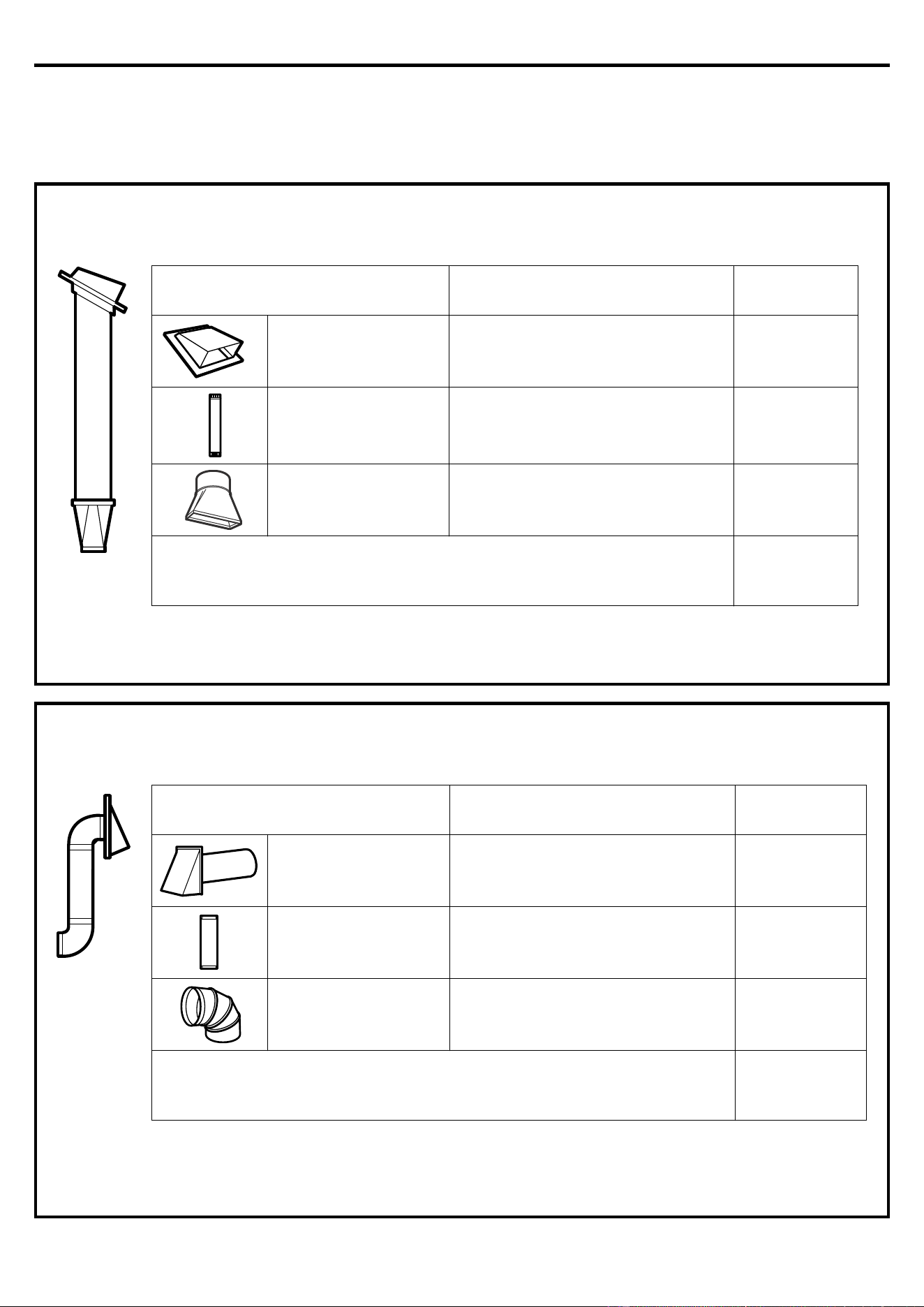
O
UTSIDE TOP EXHAUST (EXAMPLE ONLY)
The following chart describes an example of one possible ductwork installation.
* IMPORTANT: If a rectangular-to-round transition adaptor is use
d, the bottom corners of the damper will have
to be cut to fit, using the tin snips, in order to allow free movement of the damper.
TNELAVIUQESECEIP TCUD
LENGTH x
NUMBER
USED =
EQUIVALENT
LENGTH
Roof Cap 24 Ft. x (1) = 24 Ft.
12 Ft. Straight Duct (6"
Round)
12 Ft. x (1) = 12 Ft.
Rectangular-to-Round
Transition Adaptor*
5 Ft. x (1) = 5 Ft.
Equivalent lengths of duct pieces are based on actual
tests and reflect requirements for good venting
performance with any vent hood. Total Length = 41 Ft.
O
UTSIDE BACK EXHAUST (EXAMPLE ONLY)
The following chart describes an example o
f one possible ductwork installation.
NOTE: For back exhaust, care should be taken to align exhaust with space between studs, or wall should be
prepared at the time it is constructed by leaving enough space between the wall studs to accommodate
exhaust.
TNELAVIUQESECEIP TCUD
LENGTH* x
NUMBER
USED =
EQUIVALENT
LENGTH
Roof Cap 40 Ft. x (1) = 40 Ft.
3 Ft. Straight Duct
(3¼" x 10"
Rectangular)
3 Ft. x (1) = 3 Ft.
90° Elbow 10 Ft. x (2) = 20 Ft.
Equivalent lengths of duct pieces are based on actual
tests and reflect requirements for good venting
performance with any vent hood. Total Length = 63 Ft.
Installation Instructions
5
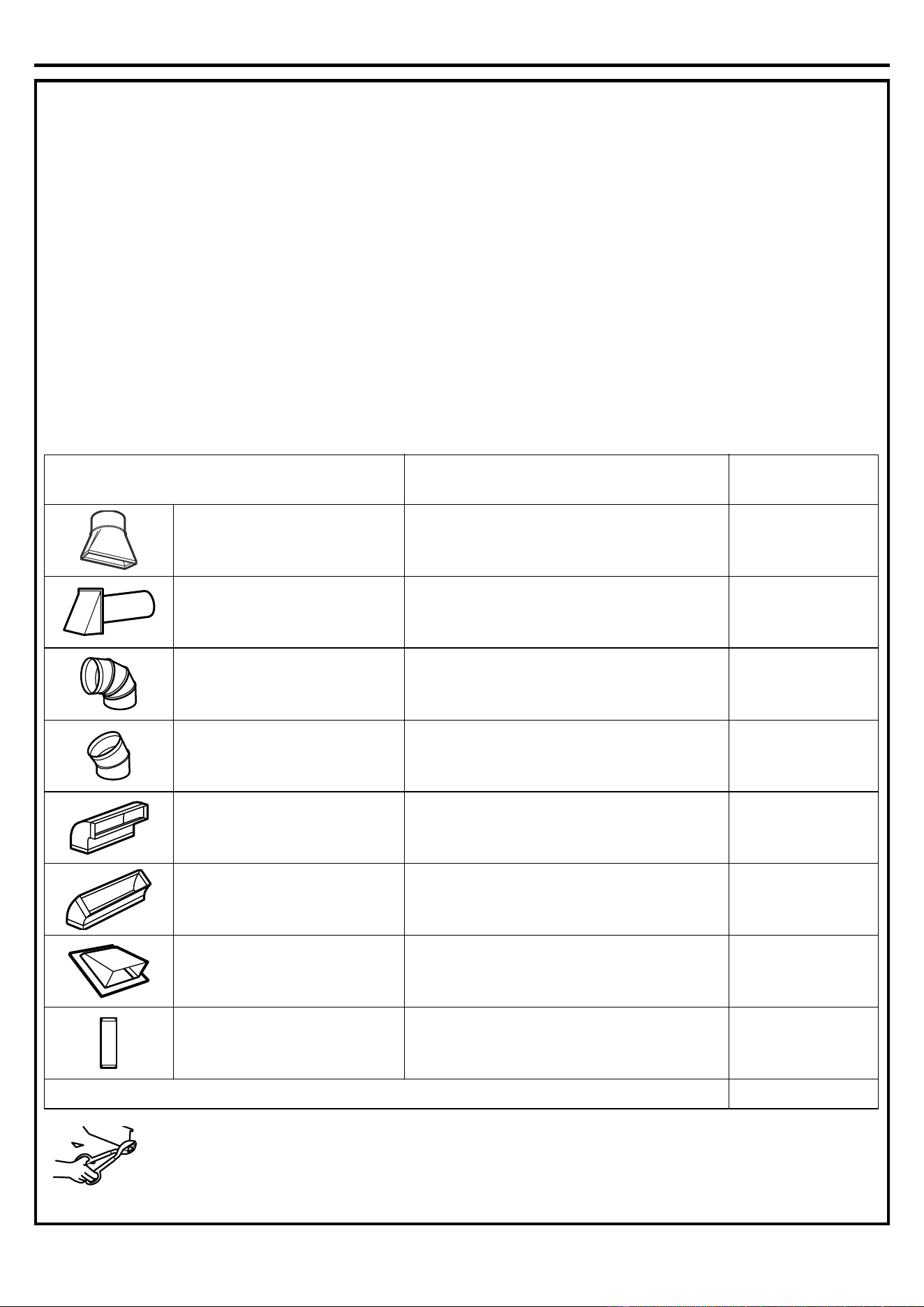
NOTE: I
f you need to install ducts, note that the total
duct length of 3¼" x 10" rectangular or 6" diameter
round duct should not exceed 140 equivalent feet.
Outside ventilation requires a HOOD EXHAUST
DUCT. Read the following carefully.
NOTE: It is important that venting be installed using
the most direct route and with as few elbows as
possible. This ensures clear venting of exhaust and
helps prevent blockages. Also, make sure dampers
swing freely and nothing is blocking the ducts.
Exhaust connection:
The hood exhaus
t has been designed to mate with a
standard 3¼" x 10" rectangular duct.
If a round duct is required, a rectangular-to-round
transition adaptor must be used. Do not use less
than a 6" diameter duct.
Maximum duct length:
For satisfactory air movement, the total duct length of
3¼" x 10" rectangular or 6" diameter round duct
should not exceed 140 equivalent feet.
Elbows, transitions, wall and roof
caps, etc.,
present additional resistance to
airflow and are equivalent to a section of straight duct
which is longer than their actual physical size. When
calculating the total duct length, add the equivalent
lengths of all transitions and adaptors plus the length
of all s
traight duct sections. The chart below shows
you how to calculate total equivalent ductwork length
using the approximate feet of equivalent length of
some typical ducts.
* IMPORTANT: If a rectangular-to-
round transition adaptor is used, the
bottom corners of the damper will
have to be cut to fit, using the tin
snips, in order to allow free movement of the damper.
Equivalent lengths of duct pieces are based on actual
tests and reflect requirements for good venting
performance with any vent hood.
TNELAVIUQESECEIP TCUD
LENGTH x
NUMBER
USED =
EQUIVALENT
LENGTH
Rectangular-to-Round
Transition Adaptor* 5 Ft. x ( ) = Ft.
Wall Cap 40 Ft. x ( ) = Ft.
90° Elbow 10 Ft. x ( ) = Ft.
45° Elbow 5 Ft. x ( ) = Ft.
90° Elbow 25 Ft. x ( ) = Ft.
45° Elbow 5 Ft. x ( ) = Ft.
Roof Cap 24 Ft. x ( ) = Ft.
Straight Duct 6" Round or
3¼" x 10" Rectangular 1 Ft. x ( ) = Ft.
Total Ductwork = Ft.
Installation Instructions
6
DAMAGE – SHIPMENT/
INSTAL
LATION
• If the unit is damaged in shipment, return the
unit to the store in which it was bought for repair
or replacement.
• If the unit is damaged by the customer, repair
or replacement is the responsibility of the
c
ustomer.
• If the unit is damaged by the installer (if other
than the customer), repair or replacement must
be made by arrangement between customer and
installer.
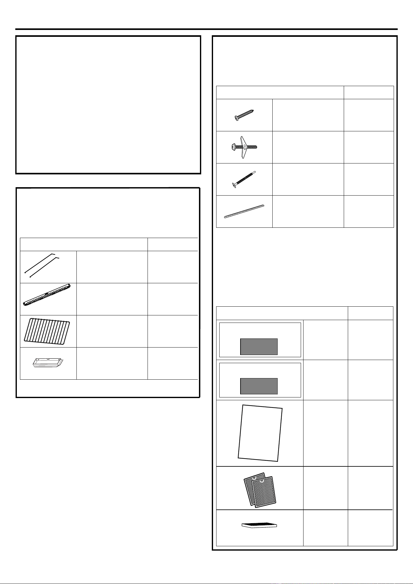
PARTS INCLUDED
HARDWARE PACKET
You will find the installation hardware contained in a
packet with the unit
. Check to make sure you have all
these parts.
NOTE: Some extra parts are included.
ADDI
TIONAL PARTS
YTITNAUQTRAP
Wood Screws
(¼" x 2")
2
Toggle Bolts
(and wing nut
s)
(
3
/
16
" x 3
")
Self-aligning
Machine Screws
(¼"-28 x 3¼")
3
Nylon Grommet
(for metal cabinets)
YTITNAUQTRAP
Top
Cabinet
Template
1
Rear Wall
Template
1
Installation
Instructions
1
Separately
Packed
Grease
Filters
2
TOP CABINET TEMPLATE
R
EAR WALL TEMPLATE
In
st
a
l
l
a
t
i
o
n
I
n
st
r
u
ctio
n
s
1
3
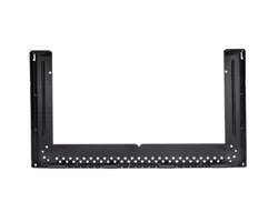
PARTS INCLUDED
YTITNAUQTRAP
Wire-Mounting 2
1
1
1
Mounting-Plate
shelf
exhaust adaptor
Cha
rcoal
Filter
1
Installation Instructions
7
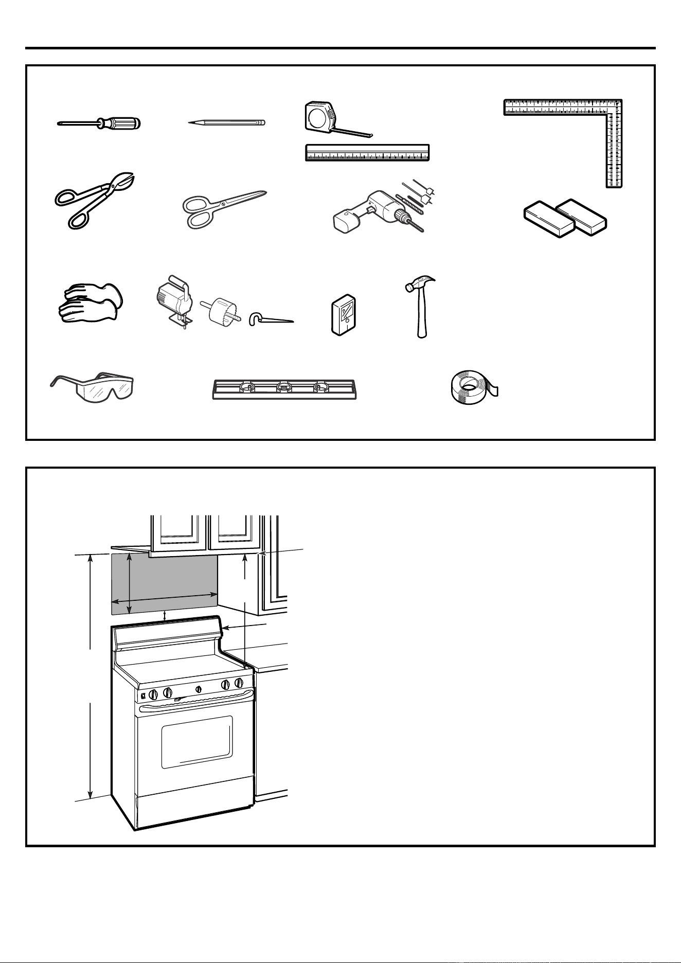
TOOLS YOU WILL NEED
# 1 a
nd #2 Phillips screwdriver
LevelSafety goggles
Stud finder or Hammer (optional)
Saw (saber, hole or keyhole)
Gloves
Scissors
(to cut template, if necessary)
Pencil
Filler blocks or scrap wood
pieces, if needed for top
cabinet spacing (used on
recessed bottom cabinet
installations only)
Duct and masking tape
Ru
ler or tape measure
and straight edge
Carpenter square
(optional)
Tin snips (for cutting
damper, if required)
Electric drill with
3
/
16
"
, ½"
and
5
/
8
" d
rill bits
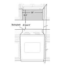
MOUNTING SPACE
NOTES:
• The space between the cabinets must be
30" wide and free of obstructions.
• I
f the space between the cabinets is greater
than 30", a Filler Panel Kit may be used to fill
in the gap between the microwave oven and
the cabinets. Your Owner’s Manual contains
the kit number for your model.
• This microwave oven is for installation over
ranges up to 36" wide.
• If you are going to vent your microwave oven
to the outside, see Hood Exhaust Section for
exhaust duct preparation.
• When installing the microwave oven
beneath smooth, flat cabinets, be careful
to follow the instructions on the top
cabinet template for power cord
clearance.
Backsplash
16-½ "
3
0"min.
2"
3
0
"
66
" or more
from the floor
to the top of the
microwave
Bottom edge of
cabinet needs
to be 30" or
more from the
cooking
surface
Installation Instructions
8
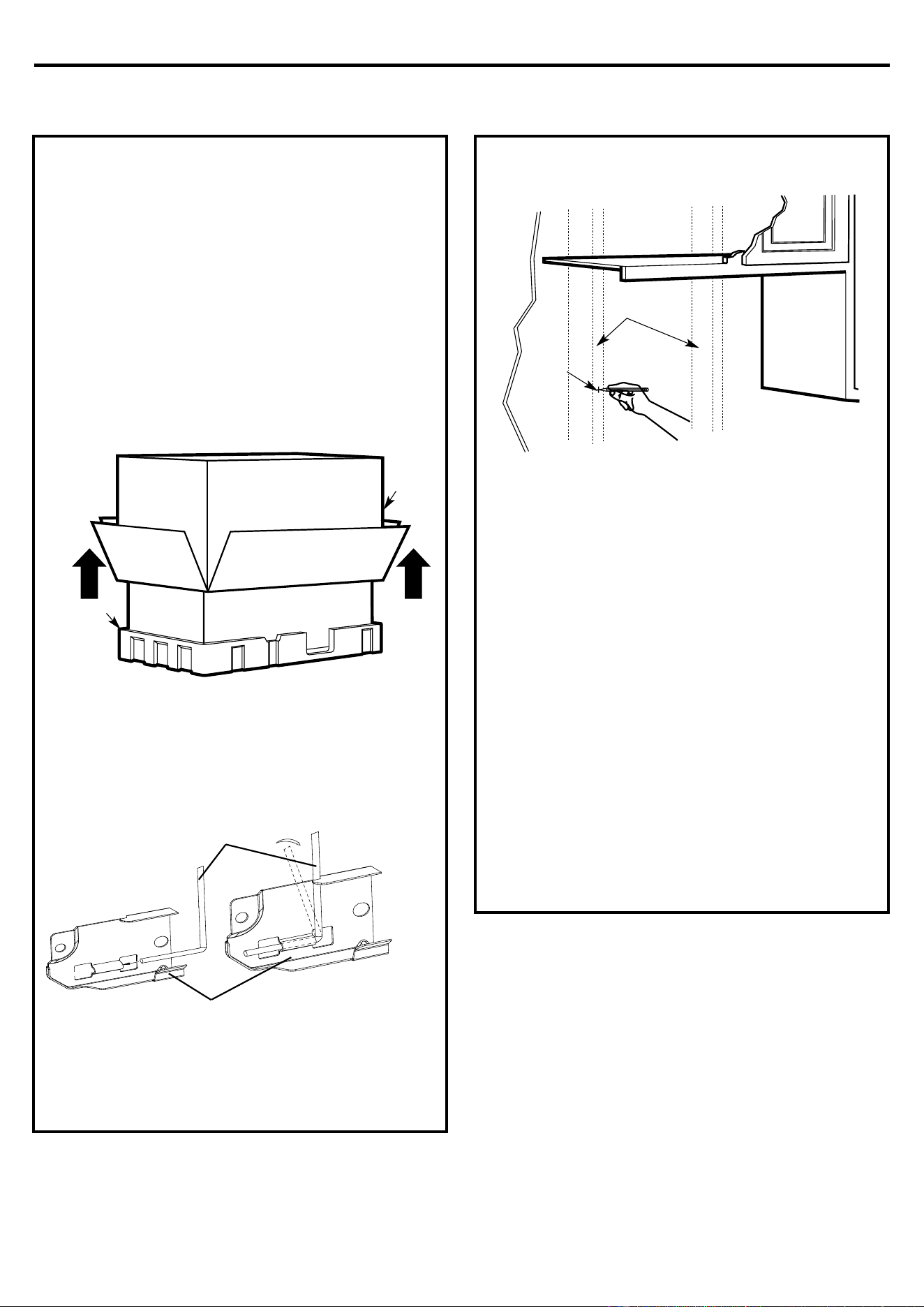
1. PLACEMENT OF THE MOUNTING PLATE
A.
REMOVING TH
E MICROWAVE
OVEN FROM THE CARTON/
ASSEMBLE THE MOUNTING
PLATE
1.
Remove the installation ins
tructions, filters, glass
tray and the small hardware bag. Do not remove
the Styrofoam protecting the front of the oven.
2.
Fold back all 4 carton flaps fully against carton
s
ides. Then carefully roll the oven and carton over
onto the top side. The oven should be resting in
the Styrofoam.
3.
Pul
l the carton up and off the oven.
4.
Remove and p
roperly discard plastic bags.
B.
F
INDING THE WALL STUDS
1.
Find the s
tuds, using one of the following
methods:
A. Stud finder–a magnetic device which locates
nails.
OR
B. Use a hammer to tap lightly across the
mounting surface to find a solid sound. This
will indicate a stud location.
2.
A
fter locating the stud(s), find the center by
probing the wall with a small nail to find the edges
of the stud. Then place a mark halfway between
the edges. The center of any adjacent studs
should be 16" or 24" from this mark.
3.
Draw a line down the center of the s
tuds.
THE MICROWAVE MUST BE CONNECTED TO AT
LEAST ONE WALL STUD.
C
arton
Styrofoam
W
all Studs
Center
5.
y
ou will be able to assemble it take following
picture.
Mounting-Plate
Wire-Mounting
Installation Instructions
9
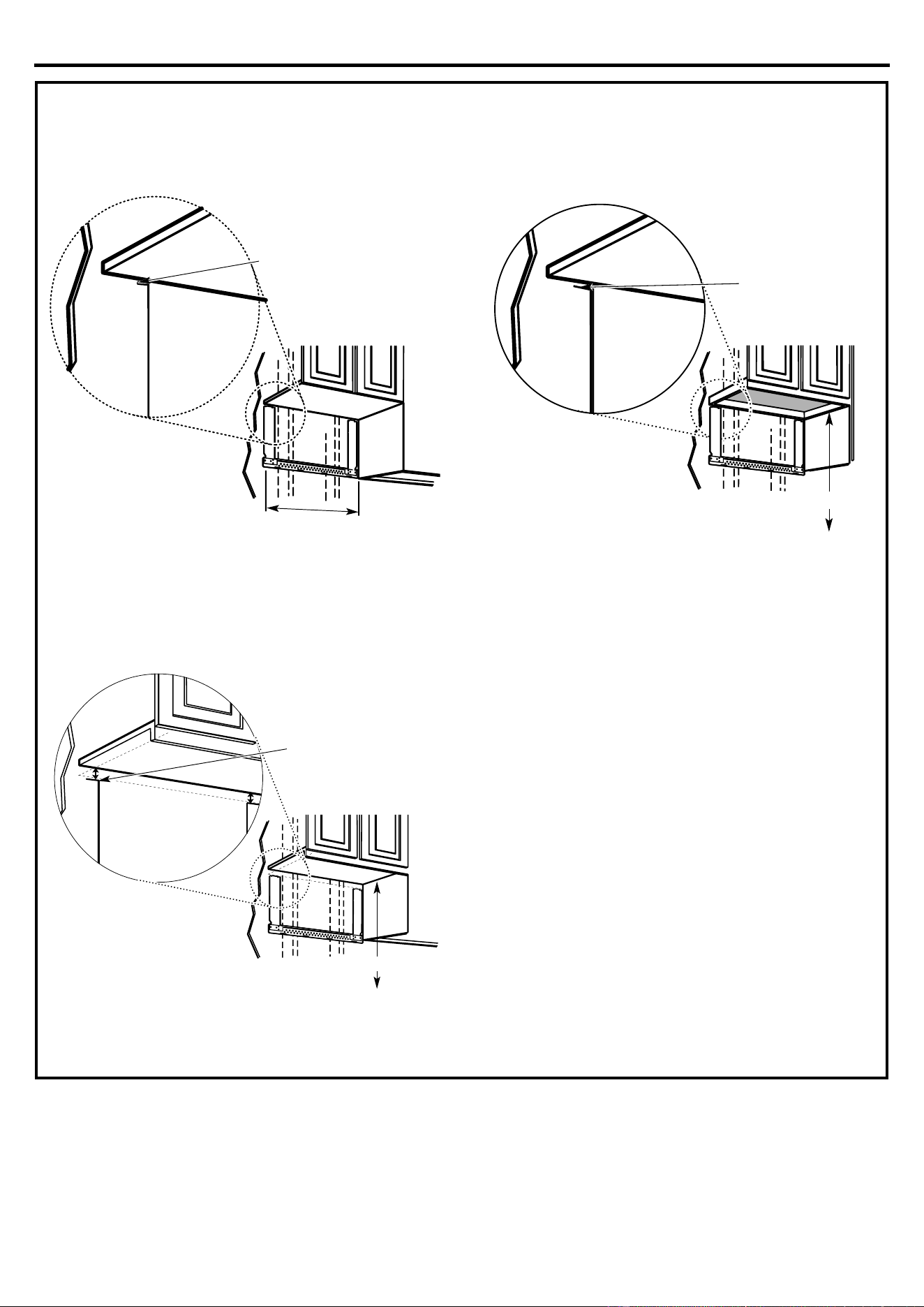
C.
DE
TERMINING WALL PLATE LOCATION UNDER YOUR CABINET
Your cabinets may have decorative trim that
interferes with the microwave installation. Remove
the decorative trim to install the microwave properly
and to make it level.
THE MICROWAVE MUST BE LEVEL.
Use a level to make sure the cabinet bot
tom is level.
If the cabinets have a front overhang only, with no
back or side frame, install the mounting plate down
the same distance as the front overhang depth. This
will keep the microwave level.
1.
Measure the inside depth of the f
ront overhang.
2.
Draw a horizontal line on the back wall an equal
distance below the cabine
t bottom as the inside
depth of the front overhang.
3.
For this type of installation with front overhang
only, align the mounting tabs with this horizontal
line, not touching the cabinet bot
tom as described
in Step D.
P
late position – beneath flat bottom cabinet
M
ounting Plate Tabs
Touching the Cabinet Bottom
A
t
l
e
a
s
t
3
0
"
P
late position – beneath recessed bottom
cabinet with front overhang
M
ounting Plate with
Tabs Below Cabinet
Bottom the Same
Distance as the Front
Overhang Depth
30" to Cooktop
P
late position – beneath framed recessed
cabinet bottom
Mou
nting Plate Tabs
Touching the Back
Frame
30" to Cooktop
Installation Instructions
10
D.
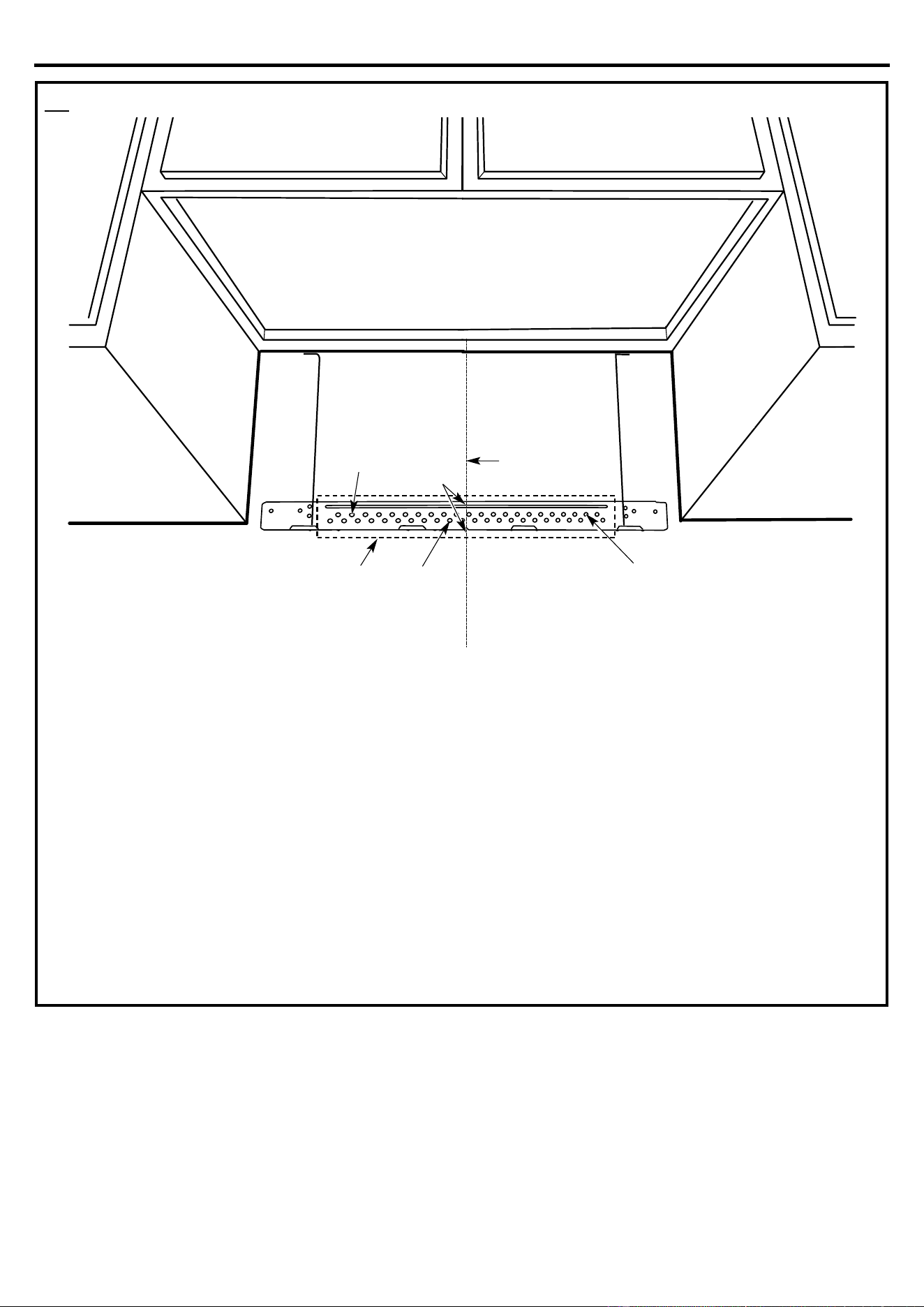
ALIGNING THE WALL PLATE
1.
Draw a vertical line on the wall at the center of the
30" wide space.
2.
Use the mounting plate as the template for the
rear wall. Place the mounting plate on the wall,
making sure that the tabs are touching the
bottom of the cabinet or the level line drawn in
Step C for cabinets with front overhang. Line
up the notch and center line on the bottom of
the mounting plate to the center line on the
wall.
3.
While holding the mounting plate with one hand,
draw circles on the wall at holes A, B, and C
(see illustration above/actual plate marked with
arrows). holes must be used for
mounting.
NOTE: Holes A,B and C are inside area E. If none of
A,B and C is in a stud, find a stud somewhere in area
E and draw a fifth circle to line up with the stud. It is
important to use at least one wood screw mounted
firmly in a stud to support the weight of the
microwave. Set the mounting plate aside.
4.
Drill holes on the circles.
If there is a stud, drill a
3
/
16
" hole for wood screws.
Three holes that don’t line up with a stud, drill
5
/
8
"
a hole for toggle bolts.
NOTE: DO NOT MOUNT THE PLATE AT THIS
TIME.
Hole CArea E
Draw a Vertical
Line on Wall
from Center of
Top Cabinet
Hole A
Hole B
Centerline
notches
CAUTION: Wear gloves to avoid
cutting fingers on sharp edges.
Three
Installation Instructions
11
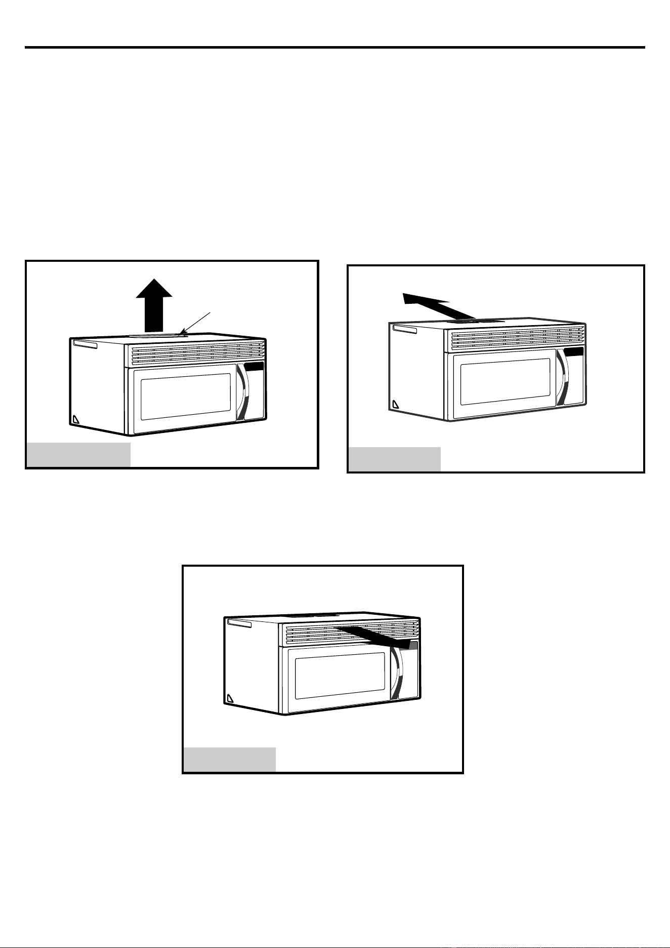
2. INSTALLATION TYPES
(Choose A, B or C)
This microwave oven is designed for adaptation to
t
he following three types of ventilation:
A. Outside Top Exhaust (Vertical Duct)
B. Outside Back Exhaust (Horizontal Duct)
C. Recirculating (Non-Vented Ductless)
NOTE: This microwave is shipped assembled for
Recirculating.
A.
O
UTSIDE TOP EXHAUST
(VERTICAL DUCT)
B.
O
UTSIDE BACK EXHAUST
(HORIZONTAL DUCT)
A Charcoal Filter
Accessory Kit is required
for the non-vented exhaust.
(See your Owner’s Manual
for the kit number.)
C.
RECIRCULAT
ING
(NON-VENTED DUCTLESS)
See p
age 12
A
daptor in Place for
Outside Top
Exhaust
S
ee page 16
S
ee page 20
Installation Instructions
12
A.
OUTSIDE TOP EXHAUST (Vertical Duct)
A
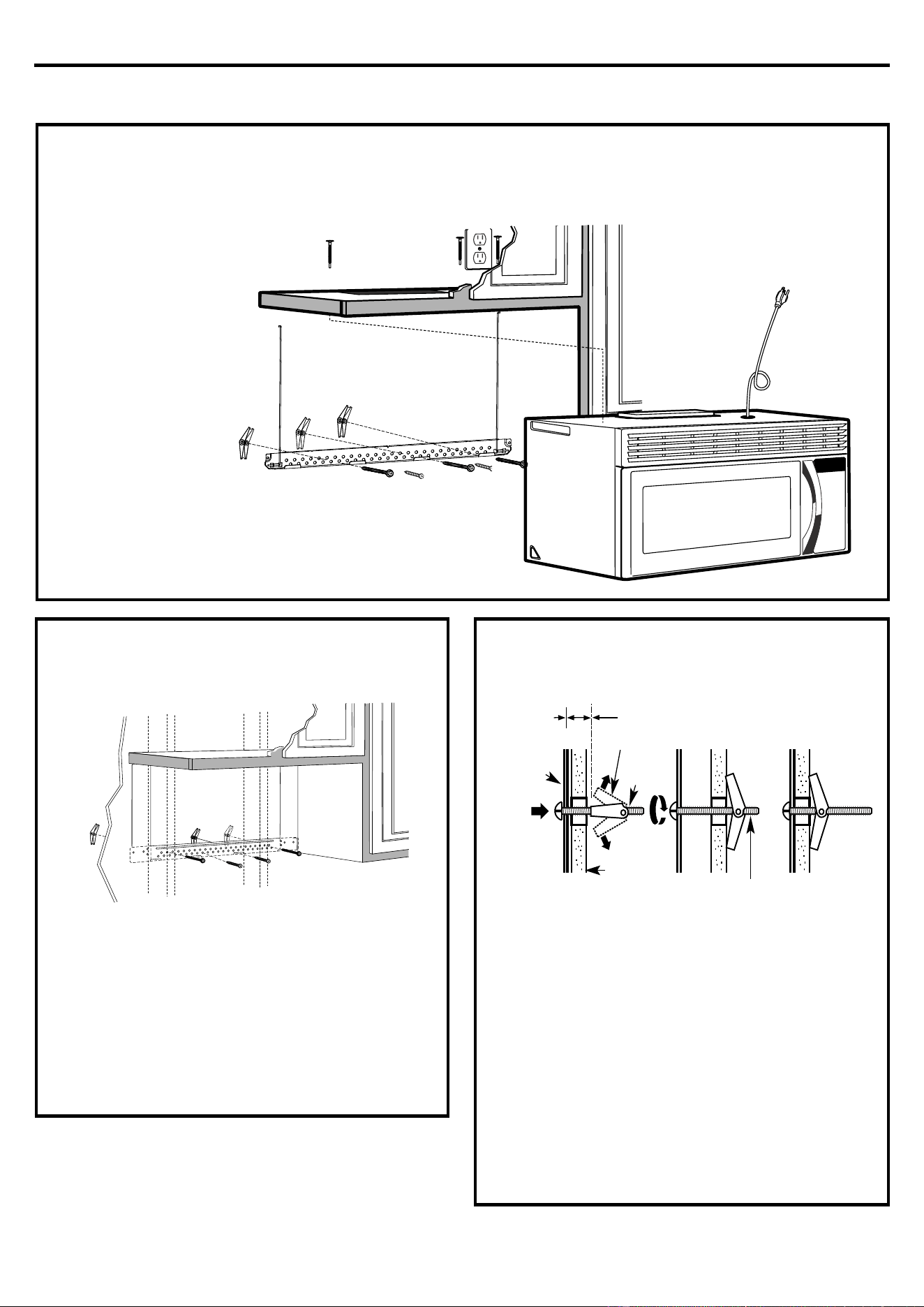
1.
ATTACH THE MOUNTING PLATE
TO THE WA
LL
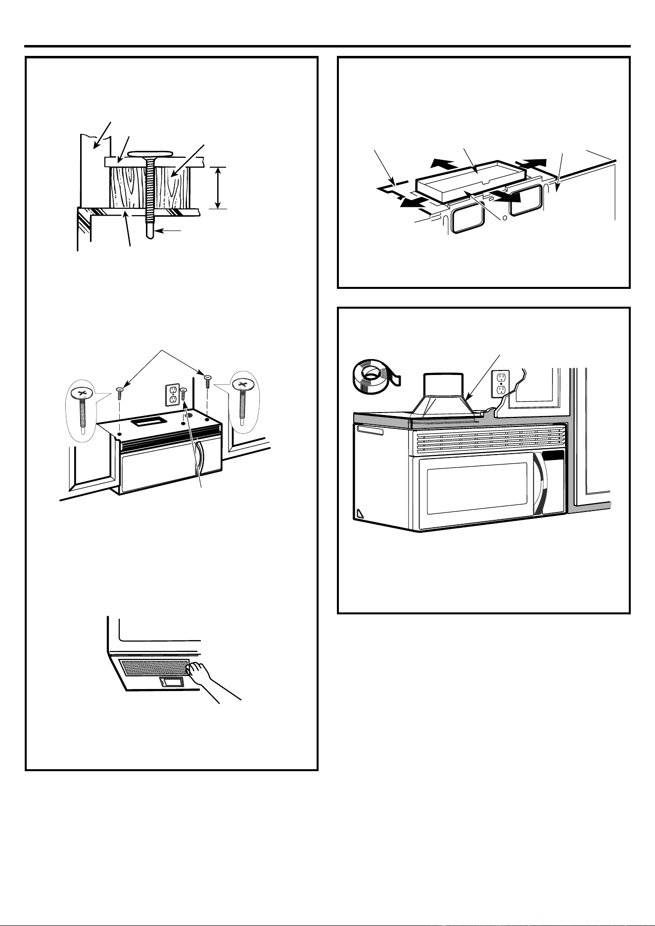
At
tach the plate to the wall using toggle bolts. At least
one wood screw must be used to attach
the plate to a wall stud.
1.
Remove the t
oggle wings from the bolts.
2.
Insert the bolts into the mounting plate through the
holes designated to go into drywall and reattach
the toggle wings to ¾" onto each bolt.
To use toggle bolts:
3.
Place the mounting plate against the wall and
insert the toggle wings into the holes in the wall to
m
ount the plate.
NOTE: Before tightening toggle bolts and wood
screw, make sure the tabs on the mounting plate
touch the bottom of the cabinet when pushed flush
against the wall and that the plate is properly centered
under the cabinet.
CAUTION: Be careful to avoid pinching fingers
between the back of the mounting plate and the wall.
4.Tighten all bolts. Pull the plate away from the wall
to help tighten the bolts.
INSTAL
LATION OVERVIEW
A1. Attach Mounting Plate to Wall
A2. P
repare Top Cabinet
A3. Check Microwave Assembly
A4. Check Damper Operation
A5. Mount Microwave Oven
A6. Adjust Exhaust Adaptor
Connect Ductwork
Moun
ting
Plate
Wall
Toggle Wings
Toggle
Bolt
Spacing for Toggles More
Than Wall Thickness
Bolt End
A7.
Installation Instructions
13
A2.
USE TOP CABINET TEMPLATE
FOR PREPARATION OF TOP
CABINET
You need to drill holes for the top support screws, a
hole large enough for the power cord to fit through,
and a cutout large enough for the exhaust adaptor.
• Read the instructions on the TOP CABINET
TEMPLATE.
• Tape it underneath the top cabinet.
• Drill the holes, following the instructions on the
TOP CABINET TEMPLATE.
CAUTION: Wear safety goggles when drilling holes
in the cabinet bottom.
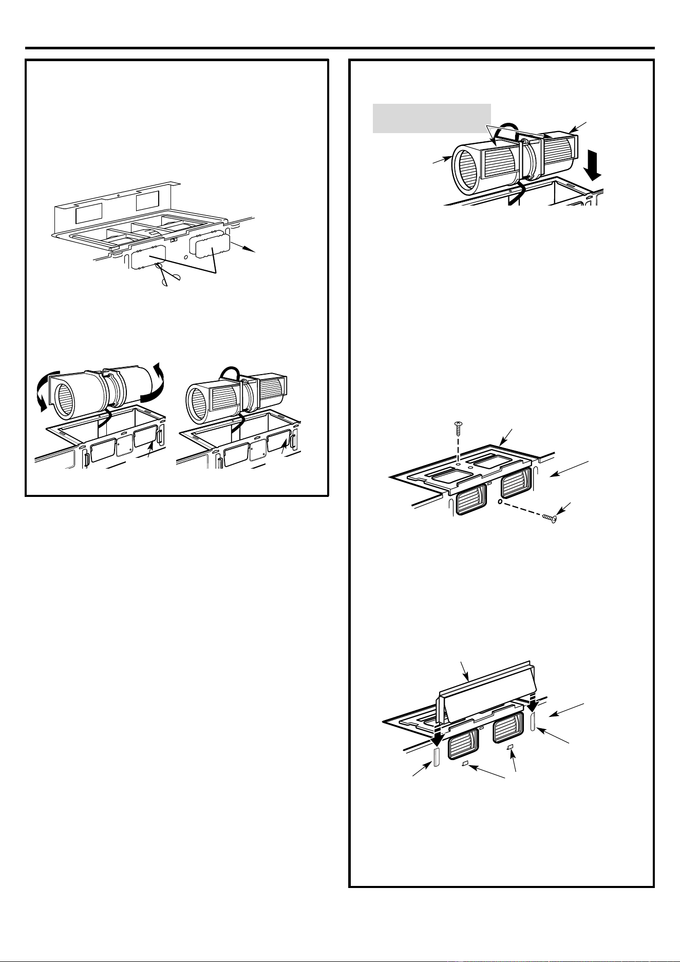
A3.
ADAPTING MICROWAVE BLOWER
FOR RECIRCULATION
2
Back o
f
Microwave
1.
Remove and save
screw that holds
blower plate to
microwave.
Scr
ew
Carefully pull out the blower unit. The wires will
extend far enough to allow you to adjust the
blower unit.
After Rolling Before Rolling
Back of
Microwave
Back of
Microwave
3.
Roll the blower unit 90° so that
fan
blade
openings
are facing out the up of the
microwave.
Place the blower unit back into the opening.
CAUTION: Do not pull or stretch the blower unit
wiring. Make sure the wires are not
pinched.
NOTE: The blower unit exhaust openings should
match exhaust openings on rear of microwave
oven.
Secure the blower unit to the microwave with the
screw from Step 1.
6.
Replace the blower plate in the same position as
before with the screw.
AFTER: Fan Blade
Openings Facing UP
Back of
Microwave
Blower Motor
Screw
Blower Plate
Back
of
Microwave
.
5
.
4.
Installation Instructions
14
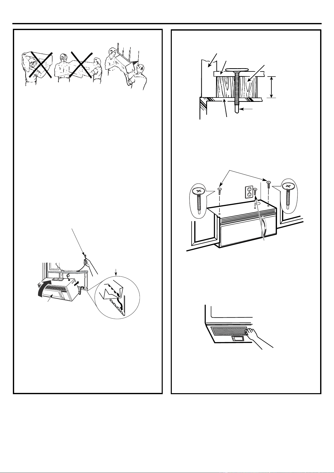
A
5.
MOUNT THE MICROWAVE OVEN
FOR EASIER INSTALLATION AND PERSONAL
SAFETY, WE RECOMMEND THAT TWO PEOPLE
INSTALL THIS MICROWAVE OVEN.
IMPORTANT: Do not grip or use handle during
installation.
NOTE: If your cabinet is metal, use the nylon
grommet around the power cord hole to prevent
cutting of the cord.
NOTE: We recommend using filler blocks if the
cabinet front hangs below the cabinet bottom shelf.
IMPORTANT: If fi
ller blocks are not used, case
damage may occur from over tightening screws.
NOTE: When mounting the microwave oven, thread
power cord through hole in bottom of top cabinet.
Keep it tight throughout Steps 1–3. Do not pinch cord
or lift oven by pulling cord.
3.
Insert a self-aligning screw through top center
cab
inet hole. Temporarily secure the oven by
turning the screw at least two full turns after the
threads have engaged. (It will be completely
tightened later.) Be sure to keep power cord
tight. Be careful not to pinch the cord,
especially when mounting flush to bottom of
cabinet.
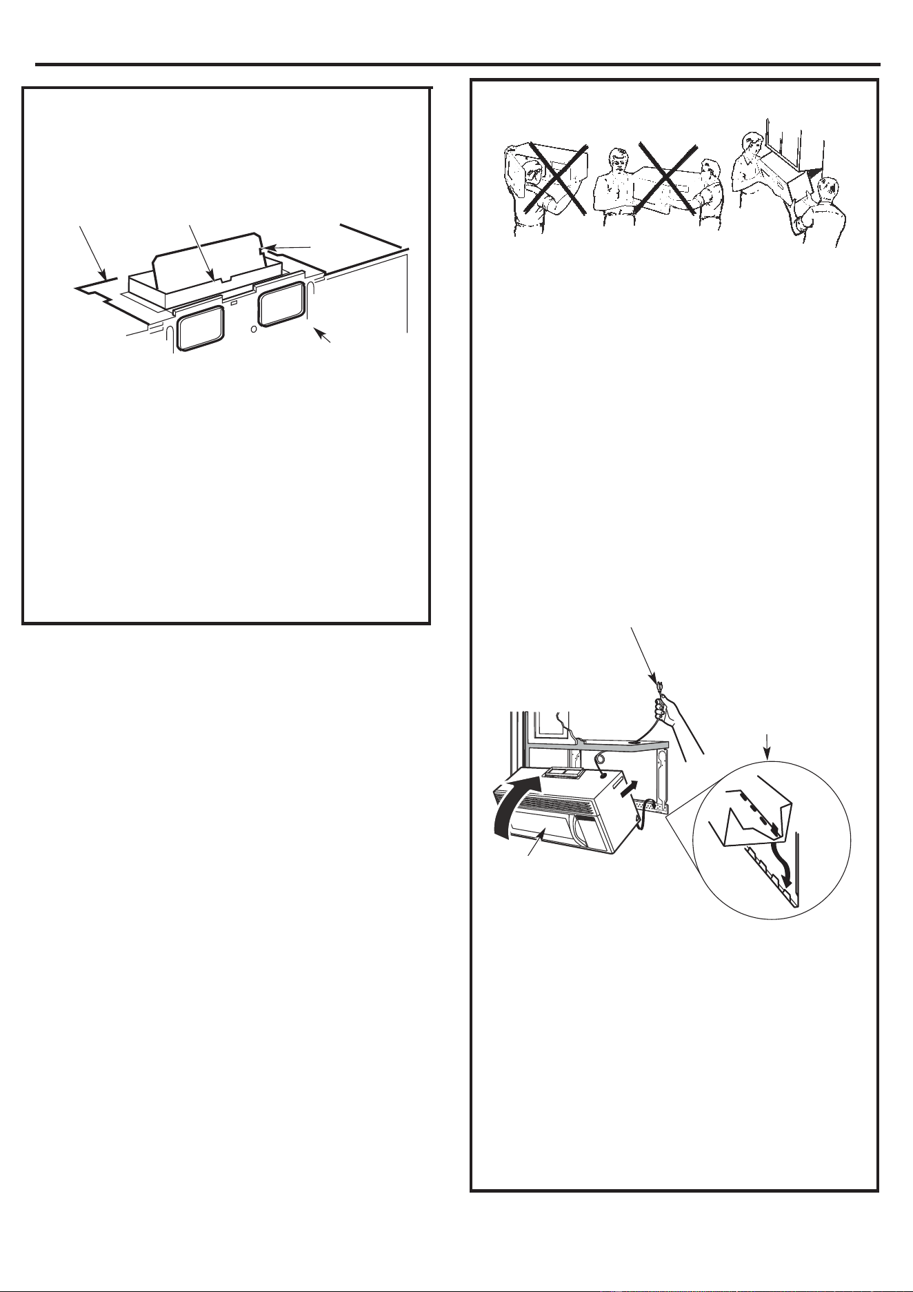
2.
Rotate front of oven
u
p against cabinet
bottom
1.
Lift microwave, tilt it
forward, and hook slot
s
at back bottom edge
onto four lower tabs of
mounting plate.
A
4.
CHECK FOR PROPER DAMPER
O
PERATION
• Place the microwave in its upright position, with
the top of the unit facing up.
• This microwave oven may be shipped assembled
for top exhaus
t (adaptor installed) or for
recirculation exhaust (adaptor absent).
• Make sure tape securing damper is removed
and damper pivots easily before mounting
microwave.
• You will need to make adjustments to assure
proper alignment with your house exhaust duct
after the microwave is installed.
E
xhaust Adaptor
(absent on models
shipped for recirculation
exhaust)
Back of
Microwave
Damper
Blower Plate
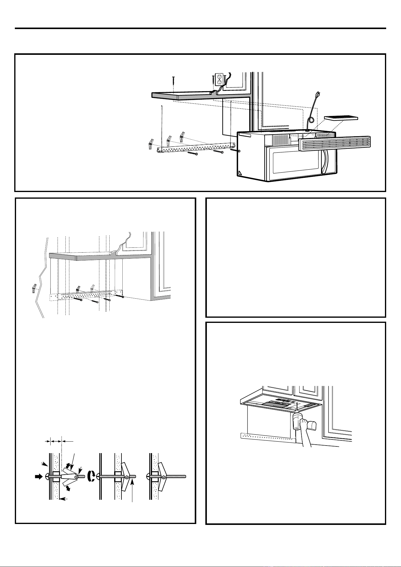
Installation Instructions
15
A
5.
MOUNT THE MICROWAVE OVEN
(cont.)
4.
Att
ach the microwave oven to the top cabinet.
7.
Tighten the outer two s
crews to the top of the
microwave oven. (While tightening screws, hold
the microwave oven in place against the wall and
the top cabinet.)
8.
Ins
tall grease filters. See the Owner’s Manual
packed with the microwave.
A
6.
A
DJUST THE EXHAUST ADAPTOR
O
pen the top cabinet and adjust the exhaust adaptor
to connect to the house duct.
A
7.
CONNECTING DUCTWORK
1.
Extend the house duct down to connect to the
exh
aust adaptor.
2.
Seal exhaust duct joints using duct tape.
Cab
inet Front
Self-Aligning Screw
Equivalent to
Depth of Cabinet
Recess
Microwave Oven Top
Filler Block
Cabinet Bottom Shelf
6.
Tighten center screw
completely.
5.
Insert 2 self-aligning screws
through outer top cabinet holes.
Turn two full turns on each screw.
Bac
k of
Microwave
Damper
For Front-to-Back or
Side-to-Side Adjustment,
Slide the Exhaust
Adaptor as Needed
Blower Plate
H
ouse Duct
Installation Instructions
16
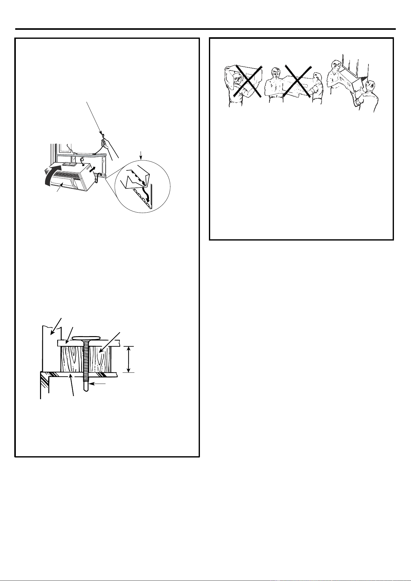
B.
O
UTSIDE BACK EXHAUST
(Horizontal Duct)
B
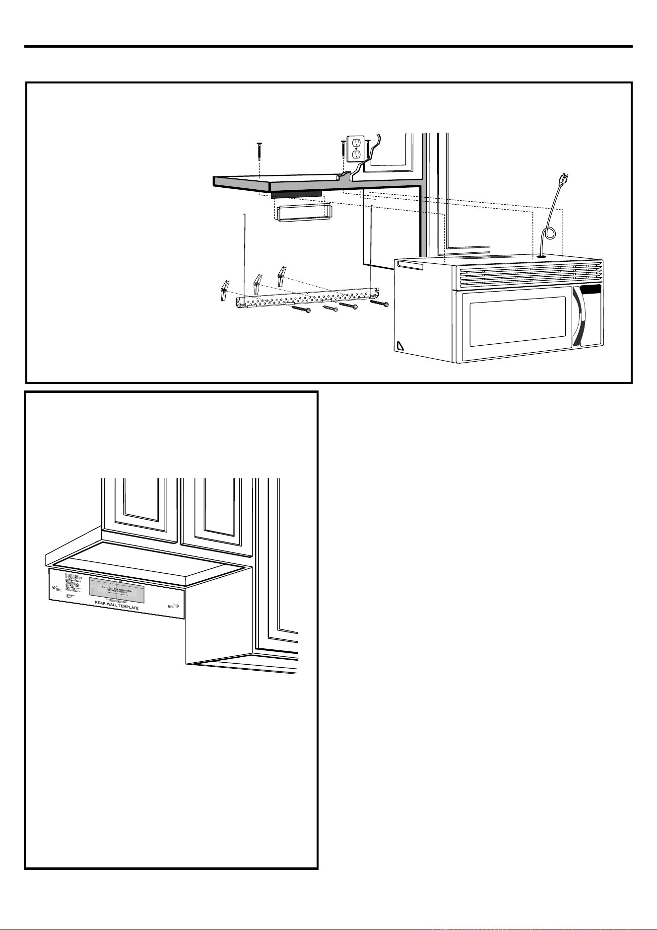
1.
PREPARING THE REAR WALL
FOR OUTSIDE BACK EXHAUST
You need to cut an opening in the rear wall for ou
tside
exhaust.
• Read the instructions on the REAR WALL
TEMPLATE.
• Tape it to the rear wall, lining up with the holes
previously drilled for holes A and B in the wall
plate.
• Cut the opening, following the instructions of the
REAR WALL TEMPLATE.
INSTAL
LATION OVERVIEW
B1. Prepare Rear Wall
B2. Attach Mounting Plate to Wall
B3. P
repare Top Cabinet
B4. Adjust Blower
B5. Mount the Microwave Oven
Installation Instructions
17
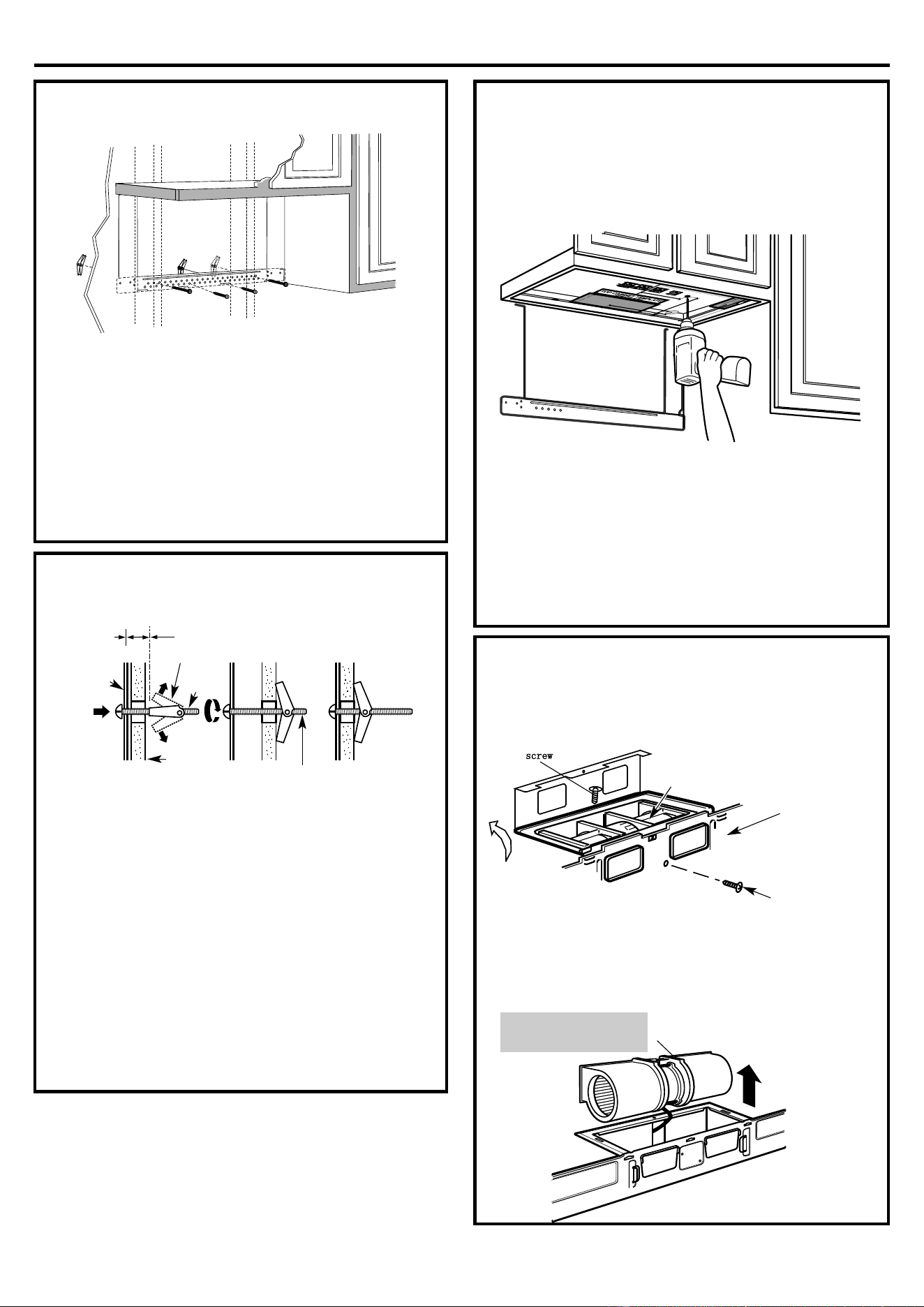
B
2.
ATTACH THE MOUNTING PLATE
A
ttach the plate to the wall using toggle bolts. At least
one wood screw must be used to attach
the plate to a wall stud.
1.
Remove the t
oggle wings from the bolts.
2.
Insert the bolts into the mounting plate through
the holes designated to go into drywall and
reattach the toggle wings to ¾ " onto each bolt.
To use toggle bolts:
3.
Place the mounting plate against the wall and
insert the toggle wings into the holes in the wall to
m
ount the plate.
NOTE: Before tightening toggle bolts and wood
screw, make sure the tabs on the mounting plate
touch the bottom of the cabinet when pushed flush
against the wall and that the plate is properly
centered under the cabinet.
CAUTION: Be careful to avoid pinching fingers
between the back of the mounting plate and the wall.
4.
Tighten all bolts. Pull the plate away from the wall
to help tighten the bolts.
B
3.
USE TOP CABINET TEMPLATE
FOR PREPARATION OF TOP
CABINET
You need to drill holes for the top support screws and
a hole
large enough for the power cord to fit through.
• Read the instructions on the TOP CABINET
TEMPLATE.
• Tape it underneath the top cabinet.
• Drill the holes, following the instructions on the
TOP CABINET TEMPLATE.
CAUTION: Wear safety goggles when drilling holes
in the cabinet bottom.
B
4.
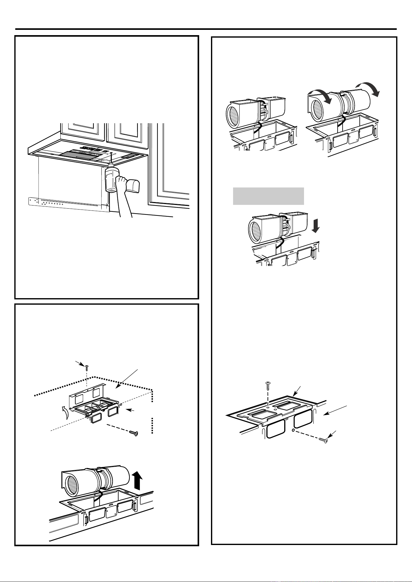
ADAPTING MICROWAVE BLOWER
F
OR OUTSIDE BACK EXHAUST
1.
Remove and save screw that holds blower motor
to micro
wave,Lift up the blower plate.
2.
Carefully pull out the blower unit. The wires will
extend far enough to allow you to adjus
t the
blower unit.
W
all
Bolt End
Toggle Wings
Toggle
Bolt
Spacing for Toggles More
Than Wall Thickness
Mounting
Plate
B
ack of
Microwave
Blower Motor
Screw
Blower Motor
BEFORE: Fan Blade
Openings Facing Front
screw
Installation Instructions
18
5.Place the blower unit back into the opening.
CAUTION: Do not pull or stretch the blower unit
w
iring. Make sure the wires are not
pinched.
NOTE: The blower unit exhaust openings should
match exhaust openings on rear of microwave
oven.
6.
Secure the blower unit to the microwave with the
screw from Step 1.
7.
Replace the blower plate in the same position as
before with the screw.
8.
At
tach the exhaust adaptor to the rear of the oven
by sliding it into the guides at the top center of the
back of the oven.
Push in securely until it is in the lower locking tabs.
Take care to assure that the damper hinge is installed
so that it is at the top and that the damper swings
freely.
Openings Facing Back
B
ack of
Microwave
Blower Motor
Screw
Blower Plate
Guide
Bac
k of
Microwave
Locking Tabs
Adaptor
Guide
AFTER: Fan Blade
Openings Facing Back
End A
End B
4.
Rot
ate blower unit counterclockwise 180°.
Part”A”
3.
R
emove “Parts A”with Nipper or Scissors.
Before Rotation After Rotation
Back of
Microwave
Back of
Microwave
B4
ADAPTING MICROWAVE BLO
F
OR OUTSIDE BACK EXHAUST
(cont.)
WER
.
Installation Instructions
1
9
B
5.
MOUNT THE MICROWAVE OVEN
FOR EASIER INSTALLATION AND PERSONAL
SAFETY, WE RECOMMEND THAT TWO PEOPLE
INSTALL THIS MICROWAVE OVEN.
IMPORTANT: Do not grip or use handle during
i
nstallation.
NOTE: If your cabinet is metal, use the nylon
grommet around the power cord hole to prevent
cutting of the cord.
NOTE: We recommend using filler blocks if the
cabinet front hangs below the cabinet bottom shelf.
IMPORTANT: If filler blocks are not used, case
damage may occur from over tightening screws.
NOTE: When mounting the microwave oven, thread
power cord through hole in bottom of top cabinet.
Keep it tight throughout Steps 1–3. Do not pinch cord
or lift oven by pulling cord.
3.
Insert a self-aligning s
crew through top center
cabinet hole. Temporarily secure the oven by
turning the screw at least two full turns after the
threads have engaged. (It will be completely
tightened later.) Be sure to keep power cord
tight. Be careful not to pinch the cord,
especially when mounting flush to bottom of
cabinet.
4.Attach the microwave oven to the top cabinet.
7.
Tighten the outer two screws to the top of the
mic
rowave oven. (While tightening screws, hold
the microwave oven in place against the wall and
the top cabinet.)
8.
Install grease filters. See the Owner’s Manual
packed with the mic
rowave.
2.
Rotate front of oven
u
p against cabinet
bottom
1.
Lift microwave, tilt it
forwa
rd, and hook slot
s
a
t back bottom edge
onto four lower tabs of
mounting plate.
Cab
inet Front
Self-Aligning Screw
Equivalent to
Depth of Cabinet
Recess
Microwave Oven Top
Filler Block
Cabinet Bottom Shelf
6.Tighten center
screw co
mpletely.
5.
Insert 2 self-aligning screws
through ou
ter top cabinet holes.
Turn two full turns on each screw.
Installation Instructions
2
0
C.
REC
IRCULATING
(Non-Vented Ductless)
C
1.
ATTACH THE MOUNTING PLATE
TO THE WA
LL
A
ttach the plate to the wall using toggle bolts. At least
one wood screw must be used to attach the plate to
a wall stud.
1.
Remove the t
oggle wings from the bolts.
2.
Insert the bolts into the mounting plate through
the holes designated to go into drywall and
reattach the toggle wings to ¾ " onto each bolt.
To use toggle bolts:
3.
P
lace the mounting plate against the wall and
insert the toggle wings into the holes in the wall to
mount the plate.
NOTE: Before tightening toggle bolts and wood
screw, make sure the tabs on the mounting plate
touch the bottom of the cabinet when pushed flush
against the wall and that the plate is properly
centered under the cabinet.
CAUTION: Be careful to avoid pinching fingers
between the back of the mounting plate and the wall.
4.
Tighten all bolts. Pull the plate
away from the wall
to help tighten the bolts.
C
2.
USE TOP CABINET TEMPLATE
FOR PREPARATION OF TOP
CABINET
You need to drill holes for the top support screws and
a hole
large enough for the power cord to fit through.
• Read the instructions on the TOP CABINET
TEMPLATE.
• Tape it underneath the top cabinet.
• Drill the holes, following the instructions on the
TOP CABINET TEMPLATE.
CAUTION: Wear safety goggles when drilling holes
in the cabinet bottom.
INSTAL
LATION OVERVIEW
C1. Attach Mounting Plate to Wall
C2. P
repare Top Cabinet
C3. Mount the Microwave Oven
C4. Install Charcoal Filter
W
all
Toggle Wings
Toggle
Bolt
Bolt End
Spacing for Toggles More
Than Wall Thickness
Mounting
Plate
Installation Instructions
21
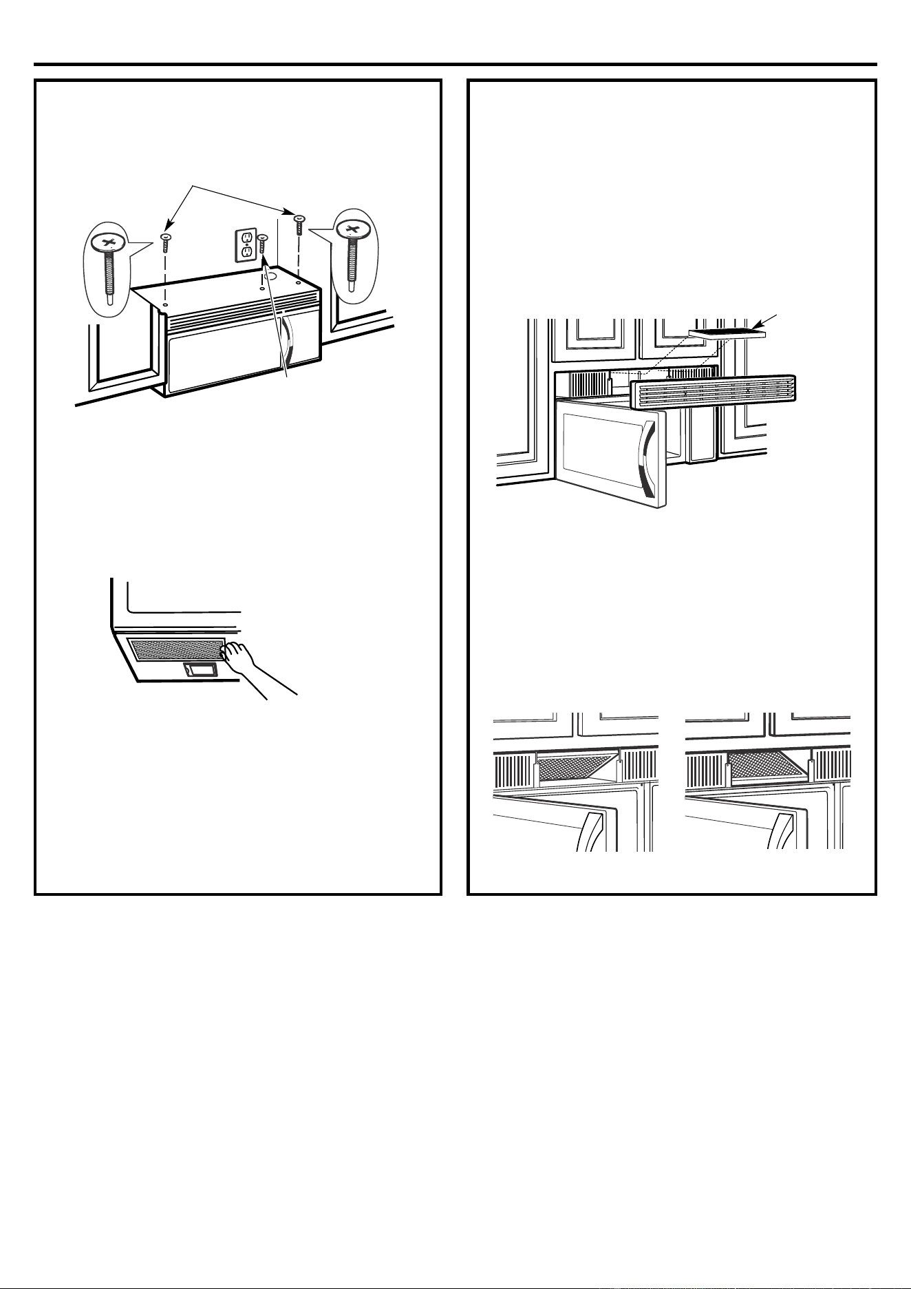
4.
Attach the microwave oven to the top cabinet.
C3.
MOUNT THE MICROWAVE OVEN
FOR EASIER INSTALLATION AND PERSONAL
SAFETY, WE RECOMMEND THAT TWO PEOPLE
INSTALL THIS MICROWAVE OVEN.
IMPORTANT: Do not grip or use handle during
installati
on.
NOTE: If your cabinet is metal, use the nylon
grommet around the power cord hole to prevent
cutting of the cord.
NOTE: We recommend using filler blocks if the
cabinet front hangs below the cabinet bottom shelf.
IMPORTANT: If filler blocks are not used, case
damage may occur from over tightening screws.
NOTE: When mounting the microwave oven, thread
power cord through hole in bottom of top cabinet.
Keep it tight throughout Steps 1–3. Do not pinch cord
or lift oven by pulling cord.
3.
Insert a self-aligning screw through top center
cabinet hole. Temporarily secure the oven by
turning the screw at least two full turns after the
threads have engaged. (It will be completely
tightened later.) Be sure to keep power cord
ti
ght. Be careful not to pinch the cord,
especially when mounting flush to bottom of
cabinet.
2.Rotate front of oven
up against cabinet
bottom
1.
Lift microwave, tilt it
forward, and hook slot
s
at back bot
tom edge
onto four lower tabs of
mounting plate.
Cabinet Front
Se
lf-Aligning Screw
Equivalent to
Depth of
Cabinet Recess
Microwave Oven Top
Filler Block
Cabinet Bottom Shelf
WARNING
Installation Instructions
22
C3
MOUNT THE MICROWAVE OVEN
(cont.)
7.
Tighten the outer two screws to the top of the
microwave oven. (While tightening screws, hold
the microwave oven in place against the wall and
the top cabinet.)
8.
Install grease filters. See the Owner’s Manual
packed with the microwave.
C4
.
INSTALLING THE CHARCOAL
FILTER
1.
Remove screws on top of grille using a #1 Phillips
screwdriver.
2.
Open the door.
3.
Remove the grille.
• Pull the grille straight off.
4.
Install the charcoal filter. When properly installed,
the wire mesh of the filter should be visible from
the front.
5.
Replace the grille and the screws.
6.
Close the door.
6.
Tighten center
screw completely.
5.
Insert 2 self-aligning screws
thro
ugh
outer
cabinet holes.
Turn two full turns on each screw.
Cha
rcoal
Filter
Insert mesh-side upInsert mesh-side down
MO1
4XX Series Models
MO16XX Series Models
.
(Continued)
top
Installation Instructions
23
BEFORE YOU USE YOUR MICROWAVE
1.
Make sure the microwave oven has been installed
according to instructions.
2.
Remove all packing material from the microwave
oven.
3.
Install turntable and ring in cavity.
4.
Replace house fuse or turn breaker back on.
5.
Plug power cord into a dedicated 20 amp
electrical outlet.
6.
Read the Owner’s Manual.
7.
KEEP INSTALLATION INSTRUCTIONS FOR
THE LOCAL INSPECTOR’S USE.
Insure proper
ground exis
ts
before use