
User Manual
Bedienungsanleitung
de
en
6-channel amplier with 8-channel DSP
6-Kanal Verstärker mit 8-Kanal DSP
206 DSP

Sehr geehrter Kunde,
Wir gratulieren Ihnen zum Kauf dieses
hochwertigen HELIX-Digitalverstärkers.
Audiotec Fischer setzt mit dem AMPLIFY 206 DSP
neue Maßstäbe im Bereich der Verstärkertechnik.
Dabei protieren Sie als Kunde direkt von unserer
mehr als 35-jährigen Erfahrung in der Forschung
und Entwicklung von Audiokomponenten.
Dieser Verstärker wurde von uns nach neuesten
technischen Erkenntnissen entwickelt und
zeichnet sich durch hervorragende Verarbeitung
und eine überzeugende Anwendung ausgereifter
Technologien aus.
Viel Freude an diesem Produkt wünscht Ihnen das
Team von
AUDIOTEC FISCHER
Allgemeines zum Einbau von HELIX-Kompo-
nenten
Um alle Möglichkeiten des Produktes optimal aus-
schöpfen zu können, lesen Sie bitte sorgfältig die
nachfolgenden Installationshinweise. Wir garan-
tieren, dass jedes Gerät vor Versand auf seinen
einwandfreien Zustand überprüft wurde.
Vor Beginn der Installation unterbrechen Sie
den Minusanschluss der Autobatterie.
Wir empfehlen Ihnen, die Installation von einem
Einbauspezialisten vornehmen zu lassen, da
der Nachweis eines fachgerechten Einbaus und
Anschlusses des Gerätes Voraussetzung für die
Garantieleistungen sind.
Installieren Sie Ihren Verstärker an einer tro-
ckenen Stelle im Auto und vergewissern Sie sich,
dass der Verstärker am Montageort genügend
Kühlung erhält. Montieren Sie das Gerät nicht in
zu kleine, abgeschlossene Gehäuse ohne Luft-
zirkulation oder in der Nähe von wärmeabstrah-
lenden Teilen oder elektronischen Steuerungen
des Fahrzeuges. Im Sinne der Unfallsicherheit
muss der Verstärker professionell befestigt wer-
den. Dies geschieht über Schrauben, die in eine
Montageäche eingeschraubt werden, die wiede-
rum genügend Halt bieten muss.
Bevor Sie die Schrauben im Montagefeld befe-
stigen, vergewissern Sie sich, dass keine elekt-
rischen Kabel und Komponenten, hydraulische
Bremsleitungen, der Benzintank etc. dahinter
verborgen sind. Diese könnten sonst beschädigt
werden. Achten Sie bitte darauf, dass sich solche
Teile auch in der doppelten Wandverkleidung ver-
bergen können.
Allgemeines zum Anschluss des HELIX
AMPLIFY 206 DSP Verstärkers
Der Verstärker darf nur in Kraftfahrzeuge einge-
baut werden, die den 12 V-Minuspol an Masse
haben. Bei anderen Systemen können der HELIX
Verstärker und die elektrische Anlage des Kfz be-
schädigt werden. Die Plusleitung für die gesamte
Anlage sollte in einem Abstand von max. 30 cm
von der Batterie mit einer Hauptsicherung abge-
sichert werden. Der Wert der Sicherung errechnet
sich aus der maximalen Stromaufnahme der Car-
Hi Anlage.
Verwenden Sie zum Anschluss des Verstär-
kers an die Stromversorgung des Fahrzeugs
ausschließlich geeignete Kabel mit ausrei-
chendem Kabelquerschnitt. Die Sicherungen
im Verstärker dürfen nur mit den gleichen Wer-
ten (3 x 25 A) ersetzt werden, um eine Beschä-
digung des Gerätes zu verhindern. Höhere
Werte können zu gefährlichen Folgeschäden
führen!
Die Kabelverbindungen müssen so verlegt sein,
dass keine Klemm-, Quetsch- oder Bruchgefahr
besteht. Bei scharfen Kanten (Blechdurchfüh-
rungen) müssen alle Kabel gegen Durchscheuern
gepolstert sein. Ferner darf das Versorgungskabel
niemals mit Zuleitungen zu Vorrichtungen des Kfz
(Lüftermotoren, Brandkontrollmodulen, Benzinlei-
tungen etc.) verlegt werden.
Herzlichen Glückwunsch!
Allgemeine Hinweise
3
de
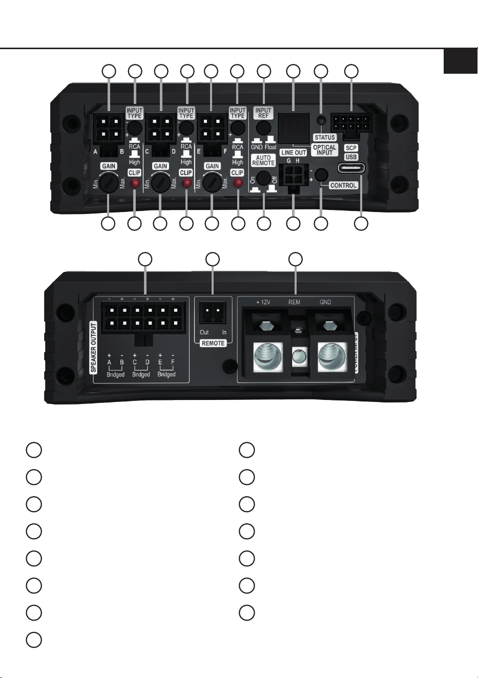
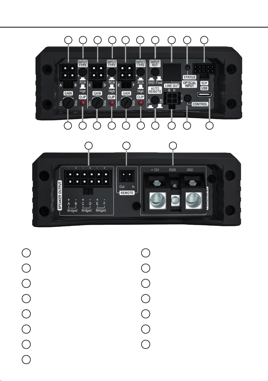
Anschluss- und Bedienelemente
1
Signaleingänge High- oder Lowlevel
Seite 5, Punkt 2
2
Eingangsmodus-Schalter
Seite 5, Punkt 1
3
Masseschalter
Seite 9, Punkt 14
4
Optischer Digitaleingang
Seite 6, Punkt 3
5
Status LED
Seite 11, Punkt 1
6
SCP (Smart Control Port)
Seite 11, Punkt 2
7
Gain-Regler
Seite 8, Punkt 7
8
Clipping LED
Seite 11, Punkt 3
9
Auto Remote-Schalter
Seite 6, Punkt 4
10
Vorverstärkerausgänge
Seite 9, Punkt 11
11
Control Taster
Seite 11, Punkt 4
12
USB-C Eingang
Seite 7, Punkt 6
13
Lautsprecherausgänge
Seite 9, Punkt 10
14
Remote Ein- und Ausgang
Seite 9, Punkt 13 & Punkt 12
15
Anschluss Stromversorgung & Remote
Seite 7, Punkt 5
1 32 4 5
13 14 15
7 9 118 10 12
1 2 1 2 6
7 8 7 8
4
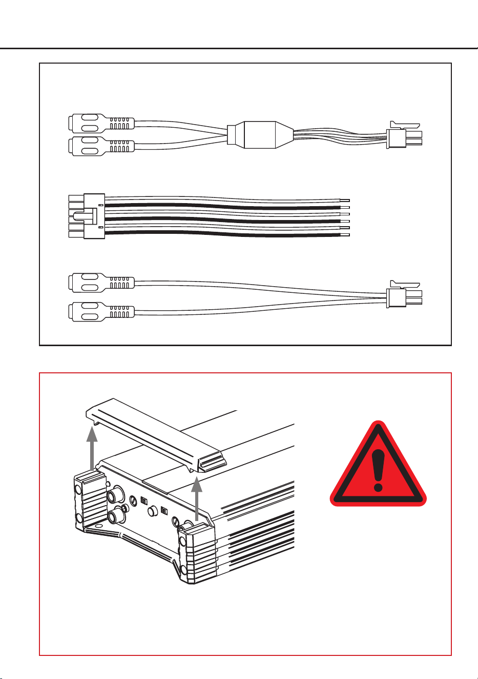
Hardware-Konguration
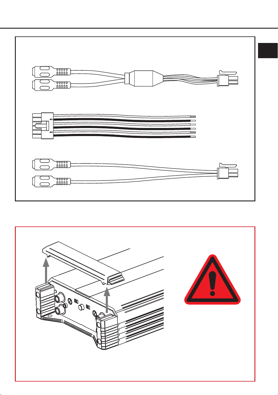
Abb. 1: Übersicht Anschlusskabel
1.1: Anschlusskabel Signaleingänge A/B, C/D & E/F (High- & Lowlevel)
1.2: Anschlusskabel Lautsprecherausgänge A bis F
Abb. 2: Abnehmen der Abdeckblende für vereinfachten Zugang zu den Anschluss- und Bedienelementen
Die Abdeckblende wird durch zwei starke Magneten sicher am Kühlkörper gehalten. Zum Entfernen
ziehen Sie die Blende einfach senkrecht nach oben ab. Nach Abschluss aller Anschlüsse und
Einstellungen setzen Sie die Blende wieder auf und achten darauf, dass sie korrekt und ohne
Verkanten sitzt.
ACHTUNG!
Heben sie das Gerät nicht
an den Abdeckblenden an
um Schäden zu vermeiden.
1.3: Anschlusskabel Vorverstärkerausgänge G & H (Line Out)1.3: Anschlusskabel Vorverstärkerausgänge G & H (Line Out)

5
de
Kongurieren Sie den HELIX AMPLIFY
206 DSP in der nachfolgenden Reihenfolge
Achtung: Für die Durchführung der nachfol-
genden Schritte werden Spezialwerkzeuge und
Fachwissen benötigt. Um Anschlussfehler und
Beschädigungen zu vermeiden, fragen Sie im
Zweifelsfall Ihren Einbauspezialisten und beach-
ten Sie zwingend die allgemeinen Anschluss- und
Einbauhinweise (siehe Seite 3). Für einen bes-
seren Zugang zu den Anschluss- und Bedienel-
ementen empehlt es sich, die Abdeckblenden
des Verstärkers, wie auf Seite 4 in Abb. 2 darge-
stellt, zu entfernen.
1. Einstellung des Eingangsspannungs-
bereichs und der Eingangsimpedanz
(ADEP.3) der analogen Signaleinänge
WICHTIG: Diese Einstellung muss zwingend
vor der ersten Inbetriebnahme vorgenommen
werden, um Schäden am Verstärker oder
dem angeschlossenen Soundsystem zu ver-
meiden.
Die analogen Eingangskanäle des Verstär-
kers können kanalpaarweise entweder mit
Low level- (Cinch / RCA) oder Highlevel-
Signalen (Lautsprecherleitungen) des Steuer-
geräts angesteuert werden. Um eine optimale
Signal qualität sicherzustellen, muss der Ein-
gangsspannungsbereich und die Impedanz
(ADEP.3) des Eingangs mit den Eingangs-
modus-Schaltern (Seite 3, Punkt 2) für jedes
Kanalpaar entsprechend des verwendeten
Signaltyps eingestellt werden.
RCA: Wählen Sie diese Einstellung, wenn Sie
den analogen Signaleingang mit Cinch / RCA-
Kabeln (Lowlevel-Signalen) des Steuergeräts
verbinden. Der Eingangsspannungsbereich
liegt hier zwischen 1 und 8 Volt.
High: Wählen Sie diese Einstellung, wenn Sie
Highlevel-Signale verwenden. Dies ist erfor-
derlich, wenn das Steuergerät keine Cinch /
RCA-Ausgänge besitzt, beispielsweise bei
Original-Autoradios / OEM Headunits. In die-
sem Fall erfolgt die Signalübertragung über
die Lautsprecherleitungen und der Eingangs-
spannungsbereich des Verstärkers beträgt 2
bis 16 Volt.
2. Anschluss der Signaleingänge (High- oder
Lowlevel)
Mit den beiliegenden Anschlusskabeln (Sei-
te 4, Abb. 1, Punkt 1.1) können die Signalein-
gänge des Verstärkers (A/B, C/D und E/F;
Seite 3, Punkt 1) mit der Signalquelle verbun-
den werden.
Mit Hilfe der DSP PC-Tool Software können
die Eingangssignale auf die Ausgangskanäle
des Verstärkers individuell aufgeteilt werden.
Sollten Sie ein normales Werksradio anschlie-
ßen, empfehlen wir folgende Kanalbelegung:
Kanal A = Vorne links
Kanal B = Vorne rechts
Kanal C = Hinten links
Kanal D = Hinten rechts
Dabei müssen nicht zwingend alle Eingän-
ge belegt werden. Werden nur zwei Kanäle
belegt, empfehlen wir die Kanäle A und B zu
verwenden. Achten Sie bitte auf eine korrekte
Polung! Wenn Sie einen oder mehrere An-
schlüsse verpolen, kann dadurch die Funktion
des Verstärkers beeinträchtigt werden.
Die Eingangsempndlichkeit kann je Kanal-
paar mit Hilfe des entsprechenden Gain-Reg-
lers optimal an die Signalquelle angepasst
werden ( Seite 8, Punkt 7).
a. Anschluss von Vorverstärker- / Low-
level- / Cinch-Signalen
Die RCA / Cinch-Ausgänge der Signalquel-
le (bspw. Nachrüst-Radio) können über
die beiliegenden Anschlusskabel (Seite 4,
Abb.1, Punkt 1.1) direkt mit den analogen
Signaleingängen A/B, C/D und / oder E/F
verbunden werden. Bei Verwendung von
Lowlevel-Signalen (Cinch / RCA) funktio-
niert die Einschaltautomatik des Verstär-
kers nicht, sodass einer der Remote-Ein-
gänge (REM oder REMOTE In) zwingend
angeschlossen werden muss.
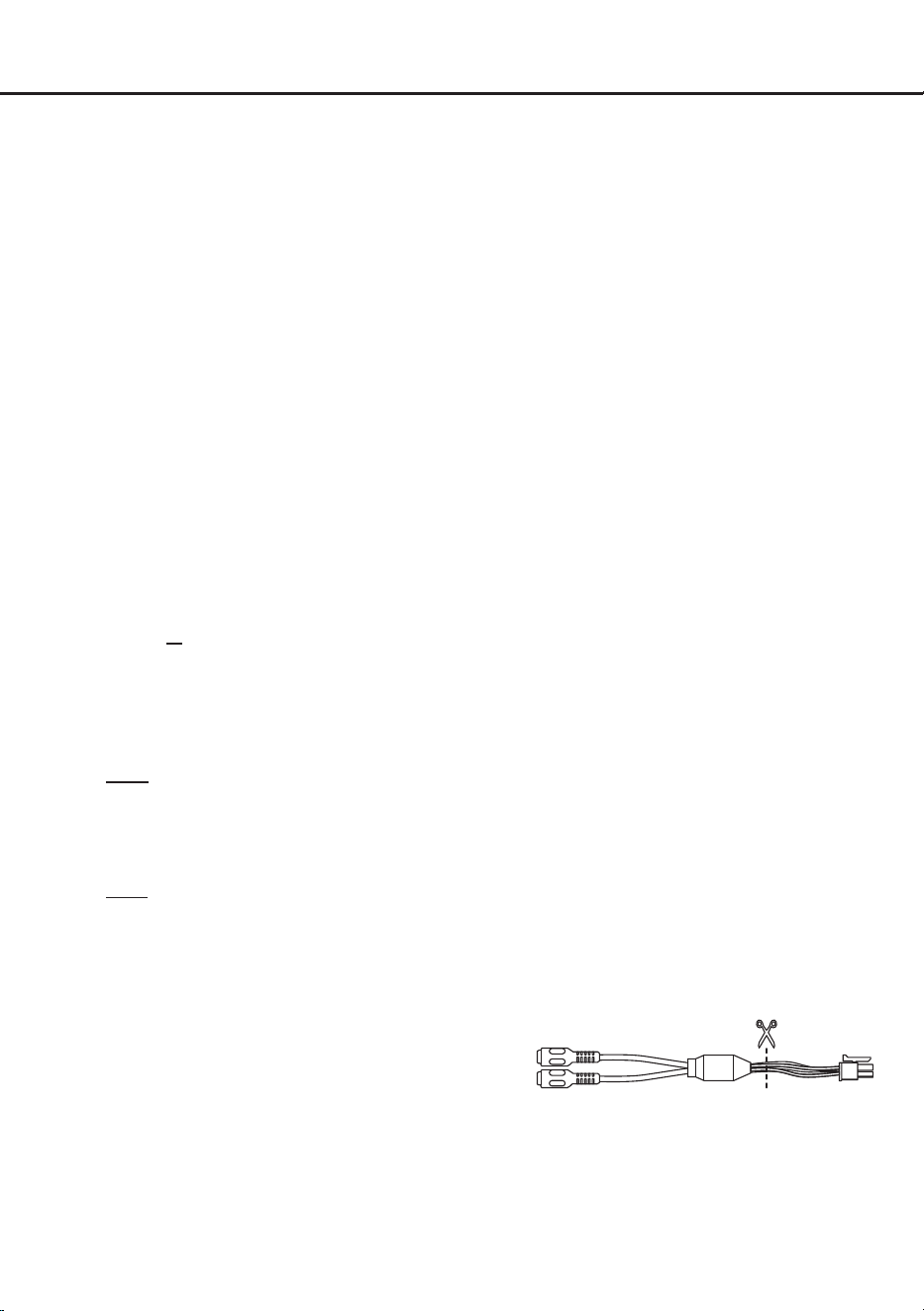
b. Anschluss von Highlevel-Signalen
(Lautsprecherleitungen)
Wenn Ihre Signalquelle (z. B. Werksradio,
OEM-Verstärker) keine Cinch / RCA-Aus-
gänge besitzt, können Sie die Lautspre-
cherausgänge mit den analogen Signalein-
gängen des Verstärkers verbinden.
Schneiden Sie dazu die Cinch / RCA-Buch-
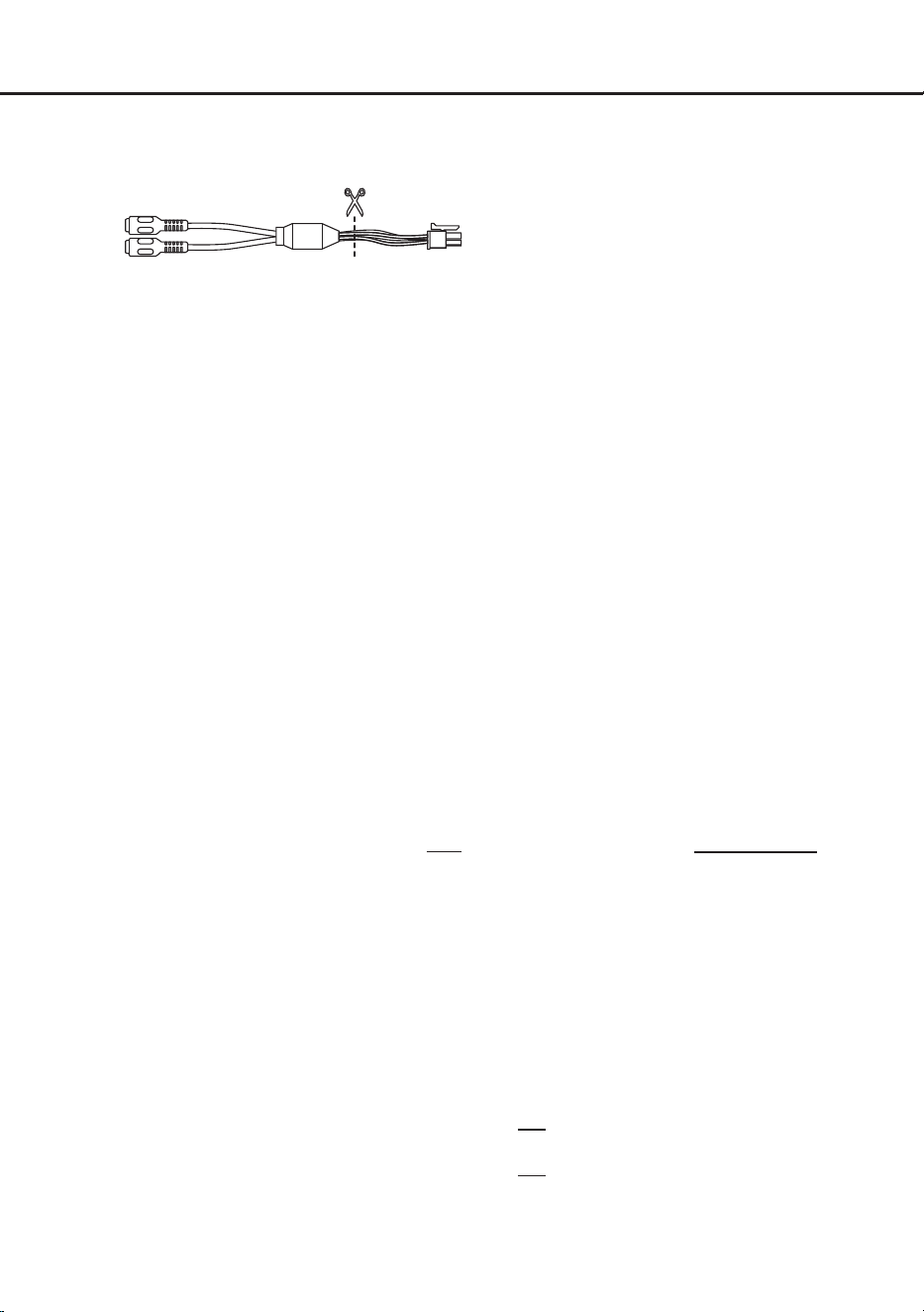
6
Hardware-Konguration
sen der beiliegenden Anschlusskabel ab,
um diese als Adapter für die Lautsprecher-
leitungen zu verwenden.
Verbinden Sie die Lautsprecherleitungen
der Signalquelle mit den vorbereiteten An-
schlusskabeln und stecken Sie diese in die
Eingänge A/B, C/D und / oder E/F des Ver-
stärkers.
Der Verstärker verfügt über den ADEP.3-
Schaltkreis (Advanced Diagnostics Error
Protection der 3. Generation), der dafür
sorgt, dass der Verstärker auch von OEM
Radios als Lautsprecher erkannt wird und
somit im Werksradio keine Funktionen de-
aktiviert werden und auch kein Eintrag im
Fehlerspeicher des Fahrzeugs erzeugt
wird. Bei Verwendung von Highlevel-
Signal en schaltet der Verstärker bei allen
handelsüblichen Radios automatisch ein,
so dass dieser nicht über einen der Remo-
te-Eingänge (REM oder REMOTE IN) ein-
geschaltet werden muss.
Achtung: Verwenden Sie zum Anschluss
ausschließlich die mitgelieferten Anschluss-
kabel (Seite 4, Abb.1, Punkt 1.1).
Hinweis: An den Signaleingängen eines Ka-
nalpaares dürfen entweder Highlevel- oder
Lowlevel-Signale (Cinch / RCA) angeschlos-
sen werden – eine gleichzeitige Verwendung
beider Signalarten an demselben Kanalpaar
führt zu Schäden am Verstärker. Es ist je-
doch möglich, unterschiedliche Kanalpaare
mit verschiedenen Signalarten zu betreiben.
Beispiel: Kanalpaar A/B wird mit Highlevel-
Signalen betrieben, während die Kanalpaare
C/D und E/F mit Lowlevel-Signalen versorgt
werden.
3. Anschluss einer digitalen Signalquelle im
SPDIF Format
Sofern Sie über eine Signalquelle mit op-
tischem Digitalausgang verfügen, kann diese
an den optischen Digitaleingang (Optical In-
put: Seite 3, Punkt 4) des Verstärkers ange-
schlossen werden. Die Abtastrate (Sampling
Rate) muss zwischen 12 - 96 kHz
liegen
. Das
Eingangssignal wird automatisch an die inter-
ne Abtastrate angepasst.
Werkseitig ist die manuelle Einschaltung des
Eingangs über eine optionale Fernbedienung
konguriert. Möchten Sie den Eingang auto-
matisch, bei Anliegen eines Audiosignals, ak-
tivieren, können Sie dies in der DSP PC-Tool
Software unter dem Tab „Signal Management
(IO)“ im Unterpunkt „Source Conguration“
kongurieren.
Die Einschaltautomatik des Verstärkers funk-
tioniert bei Verwendung des Digitaleingangs
nicht, sodass einer der Remote-Eingänge
(REM oder REMOTE In) zwingend belegt
werden muss.
Wichtig: Das digitale Audiosignal einer Quel-
le ist häug nicht lautstärkegeregelt. Das be-
deutet, dass an sämtlichen Ausgängen des
HELIX AMPLIFY 206 DSP der volle Pegel an-
liegt. Dies kann im Extremfall die Lautsprecher
zerstören. Wir raten deshalb dringend dazu,
eine optionale Fernbedienung zur Einstellung
der Lautstärke der digitalen Signaleingänge
zu verwenden!
Hinweis: Der Verstärker kann nur unkompri-
mierte, digitale Stereo PCM-Signale mit einer
Abtastrate zwischen 12 kHz und 96 kHz ver-
arbeiten.
4. Konguration des Remote-Eingangs
Diese Einstellung ist nur erforderlich, wenn
Sie die Signalquelle über Highlevel-Signale
anschließen. Die Einschaltung des Verstär-
kers erfolgt automatisch bei Ansteuerung über
ein Highlevel-Signal oder sobald ein Remote-
Signal an einem der Remote-Eingänge (REM
oder REMOTE In) anliegt. Mit Hilfe des „Auto
Remote“-Schalters (Seite 3, Punkt 9) kann die
automatische Einschaltung deaktiviert wer-
den. Dies sollte vorgenommen werden, wenn
es beispielsweise zu Störgeräuschen beim
Ein- und Ausschalten des Verstärkers kommt.
On: Einschaltung über Highlevel-Signal akti-
viert (Werkseinstellung).
O: Einschaltung über Highlevel-Signal de-
aktiviert.
Hinweis: Wird die automatische Einschaltung
des Verstärkers deaktiviert, muss einer der
Remote-Eingänge belegt werden.

7
de
5. Anschluss der Stromversorgung & Remote
ACHTUNG: Vor dem Anschluss des +12 V
Versorgungskabels an das Bordnetz muss die
Autobatterie abgeklemmt werden.
Achten Sie unbedingt auf eine korrekte Pola-
rität.
+12 V: Anschluss für die Plusleitung.
Das +12 V Stromkabel ist am Pluspol der Bat-
terie anzuschließen. Die Plusleitung sollte in
einem Abstand von max. 30 cm von der Bat-
terie mit einer Hauptsicherung abgesichert
werden. Der Wert der Sicherung errechnet
sich aus der maximalen Stromaufnahme der
gesamten Car-Hi Anlage (206 DSP = max.
93 A bei 12 V Bordnetz). Verwenden Sie bei
kurzen Leitungen (< 1 m) einen Querschnitt
von mindestens 10 mm². Bei längeren Lei-
tungen empfehlen wir einen Querschnitt von
16 mm² bis 25 mm².
GND: Anschluss für die Masseleitung. Das
Massekabel muss an einer nicht isolierten
Stelle mit dem Kfz-Chassis oder direkt mit
dem Minuspol der Autobatterie verbunden
werden. Der Kabelquerschnitt sollte den glei-
chen Durchmesser wie die Plusleitung haben.
Ein nicht ausreichender Massekontakt führt
zu unerwünschten Störgeräuschen und Fehl-
funktionen.
REM:
Der Remote-Eingang dient zum Ein-
und Ausschalten des Verstärkers,
wenn Low-
level- / Cinch-Signale oder der Digitaleingang
genutzt werden / wird.
Sofern die angeschlossene Highlevel-Signal
-
quelle die automatische Einschaltung nicht
aktiviert oder der Verstärker bewusst nur über
ein Remote-Signal ein- und ausgeschaltet wer
-
den soll, muss dieser Eingang belegt werden.
Dazu muss der Remote-Eingang des Verstär-
kers mit dem Remote-Ausgang des Radios /
der Head Unit verbunden werden. Alternativ
kann hierfür auch der zusätzliche Remote-
Eingang (REMOTE In; Seite 3, Punkt 14) ver-
wendet werden. Beide Eingänge sind intern
zusammengeschaltet und besitzen die glei-
che Funktion.
Der Eingang muss nicht belegt werden, wenn
ein Signal per Highlevel zugeführt wird. Es
wird dringend davon abgeraten, den Remo-
te-Eingang des Verstärkers über das Zün-
dungsplus des Fahrzeugs zu steuern, um
Störgeräusche beim Ein- und Ausschalten zu
vermeiden.
Wie Sie die automatische Einschaltung per
Highlevel-Signal deaktivieren können, ist auf
Seite 6 unter Punkt 4 „Konguration des Re-
mote-Eingangs“ nachzulesen.
6. Anschluss an den Computer & Einschalten
Der Verstärker kann über den USB-C-Eingang
(Seite 3, Punkt 12) mit dem Computer verbun-
den und anschließend mit dem DSP PC-Tool
konguriert werden. Verwenden Sie dazu das
beiliegende USB-Kabel.
Hinweis: Es können keine USB
Speichermedien an den Verstärker ange
-
schlossen werden. Bevor Sie den AMPLIFY
206 DSP das erste Mal mit einem Computer
verbinden, laden Sie die aktuellste DSP PC-
Tool Software (mindestens Version 6) von
unserer Homepage herunter.
Es ist ratsam,
regelmäßig nach Updates der Software zu
schauen, damit das Gerät immer auf dem ak-
tuellsten Stand ist. Die Software sowie eine
umfangreiche Knowledge Base nden Sie auf
www.audiotec-scher.com.
Es wird dringend empfohlen, die DSP PC-Tool
Knowledge Base vor der ersten Benutzung
durchzulesen, um Komplikationen und Fehler
zu vermeiden.
Wichtig: Stellen Sie sicher, dass der
AMPLIFY 206 DSP Verstärker bei der ersten
Installation der Software noch nicht am PC
angeschlossen ist. Verbinden Sie diesen erst,
wenn die Software samt der USB-Treiber voll-
ständig installiert ist.
Im folgenden Abschnitt lesen Sie die wich-
tigsten Schritte zum Anschluss und der ersten
Inbetriebnahme:
1. Laden Sie die DSP PC-Tool Software unter
www.audiotec-scher.com herunter und
installieren diese auf ihrem Computer.
2. Schließen Sie danach den Verstärker mit
dem beiliegenden USB-Kabel an den Com-
puter an. Wenn Sie längere Distanzen zu
überbrücken haben, verwenden Sie bitte
eine aktive USB-Verlängerung mit integrier-
tem Repeater.
3. Schalten Sie erst den AMPLIFY 206 DSP
ein und starten Sie anschließend die Soft-
8
Hardware-Konguration
ware. Sofern die Betriebssoftware des Ver-
stärkers nicht mehr aktuell ist, wird diese
automatisch aktualisiert.
7. Einstellung der Eingangsempndlichkeit
der analogen Signaleingänge
ACHTUNG: Es ist zwingend notwendig,
die Eingangsempndlichkeit der AMPLIFY
206 DSP an die Signalquelle anzupassen, um
eine bestmögliche Signalqualität zu garantie-
ren und Schäden am Verstärker zu vermeiden.
Außerdem ist es zuvor zwingend erforderlich
den Eingangsspannungsbereich und die Ein
-
gangsimpedanz (ADEP.3) des Signaleingangs
an die Ausgangsspannung Ihrer Signalquelle
anzupassen (Seite 5, Punkt 1).
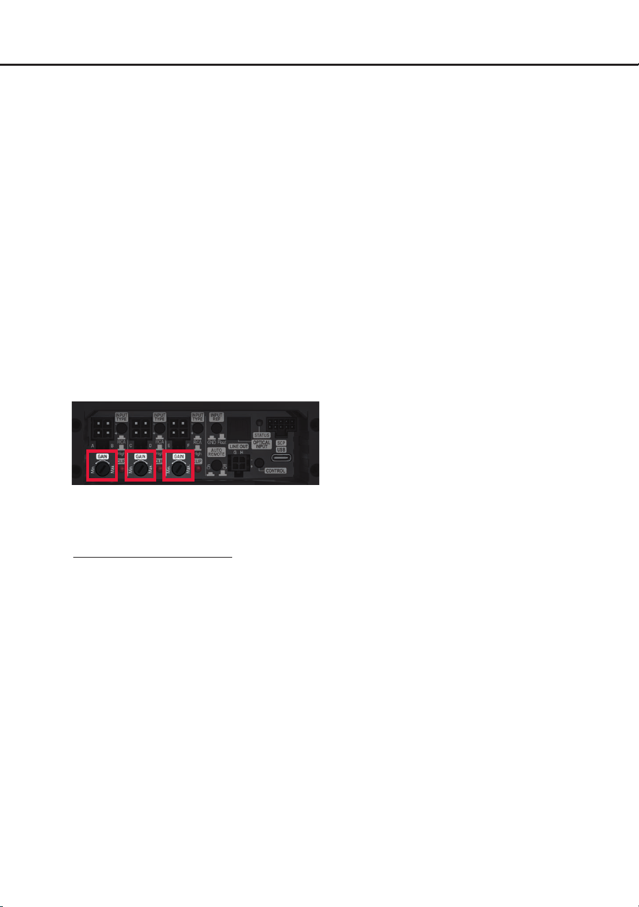
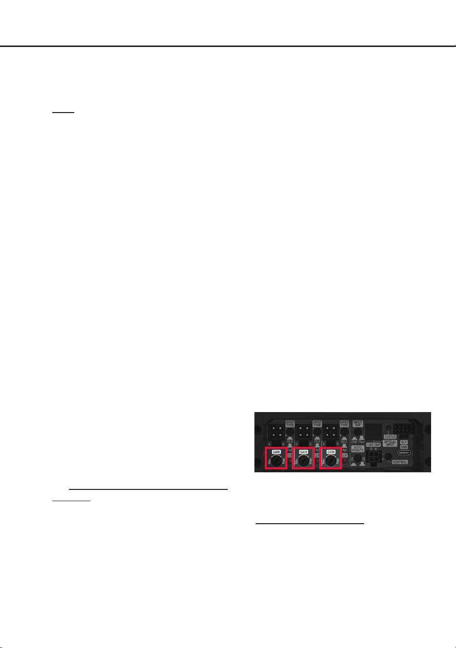
Mit Hilfe der Gain-Regler (Seite 3, Punkt 7)
kann die Eingangsempndlichkeit der Ka-
nalpaare A/B, C/D und E/F optimal an die
Signalquelle angepasst werden.
Diese Regler sind keine Lautstärkeregler,
sondern dienen nur der Anpassung.
Die Gain-Regelbereiche sind:
Highlevel: 2 - 16 Volt
Cinch: 1 - 8 Volt
Die drei Clipping LEDs (Seite 3, Punkt 8) die-
nen dabei als Kontrollinstrument.
Achtung: Schließen Sie während dieser Pro-
zedur keine Lautsprecher an die Ausgänge
des Verstärkers an und schalten Sie ggf. an-
geschlossene Verstärker ab.
Zur Anpassung der Eingangsempndlichkeit
führen Sie bitte die folgenden Schritte für je-
des Kanalpaar (A/B, C/D & E/F) nacheinander
durch:
1. Schalten Sie den Verstärker ein.
2. Drehen Sie die Lautstärke Ihres Radios auf
90 % der Gesamtlautstärke und spielen Sie
ein geeignetes Testsignal, idealerweise un-
ser speziell dafür entwickltes „IGS - Input
Gain Setup“ Signal, welches Sie unter den
„Audio Test Tracks“ des DSP PC-Tools n-
den oder auch auf www.audiotec-scher.de
downloaden können.
3. In der Regel ist die Clipping LED aus und
leuchtet nur auf, wenn einer der analogen
Signaleingänge übersteuert wird.
Erhöhen Sie die Eingangsempndlichkeit
durch Rechtsdrehung bis die Clipping LED
aueuchtet.
4. Drehen Sie nun den Gain-Regler gegen
den Uhrzeigersinn bis die Clipping LED
wieder erlischt.
5. Wiederholen Sie diesen Vorgang für jedes
weitere Kanalpaar.
8. Konguration des internen DSPs
WICHTIG: Es wird dringend empfohlen, vor
der ersten Inbetriebnahme des Soundsy-
stems die grundlegenden Einstellungen im
Verstärker mit Hilfe der DSP PC-Tool Soft-
ware vorzunehmen.
Nun können Sie den Verstärker mithilfe der
DSP PC-Tool Software frei kongurieren.
Nützliche Hinweise zur korrekten Einstellung
entnehmen Sie unserer Knowledge Base,
welche auf unserer Webseite bereit steht.
Achtung: Es wird dringend empfohlen, die
Lautstärke am Radio auf Minimum zu dre-
hen und an sämtliche Signalausgänge des
AMPLIFY 206 DSP noch nichts anzuschlie-
ßen. Speziell bei Verwendung in vollaktiven
Systemen besteht sonst Zerstörungsgefahr
für die Lautsprecher.
9. Optional: Eingangssignal analysieren
Bei Verwendung von Highlevel-Signalen an
den analogen Signaleingängen empfehlen
wir, das Eingangssignal mit Hilfe des Advan-
ced Input Signal Analyzers (AISA) der DSP
PC-Tool Software auf werkseitig eingestelltes
Equalizing, Laufzeitkorrektur und Allpass-
Filter zu überprüfen und ggfs. zu korrigieren.
Informationen zum AISA nden Sie in der um-
fangreichen Knowledge Base unserer Web-
seite www.audiotec-scher.com.

9
de
10. Anschluss der Lautsprecherausgänge
Die Lautsprecherausgänge können direkt mit
den Lautsprecherleitungen verbunden wer-
den. Verbinden Sie niemals die Lautsprecher-
leitungen mit der Kfz-Masse (Fahrzeugkaros-
serie). Dieses kann Ihren Verstärker und Ihre
Lautsprecher zerstören.
Achten Sie darauf, dass alle Lautsprecher-
systeme phasenrichtig angeschlossen sind,
d.h. Plus zu Plus und Minus zu Minus. Ver-
tauschen von Plus und Minus hat einen To-
talverlust der Basswiedergabe zur Folge. Der
Pluspol ist bei den meisten Lautsprechern ge-
kennzeichnet.
Die Impedanz pro Kanal darf 2 Ohm (im
Brückenbetrieb 4 Ohm) nicht unterschreiten,
da sonst die Schutzschaltung des Verstärkers
aktiviert wird.
Achtung: Verwenden Sie zum Anschluss der
Lautsprecher ausschließlich das mitgelieferte
Anschlusskabel mit dem 12-poligen Stecker
und den oenen Kabel enden (Seite 5, Abb. 1,
Punkt 1.2). Anschlussleitungen ungenutzter
Laut sprecherausgänge müssen zwingend ge-
gen Kurzschluss isoliert werden.
11. Optional: Anschluss der Vorverstärkeraus-
gänge G & H
Die zwei Vorverstärkerausgänge (LINE OUT
G & H) können Sie nun mit entsprechenden
Kabeln (RCA / Cinch-Kabel) mit den RCA /
Cinch-Eingängen der nachgeschalteten Ver-
stärker verbinden.
Die Ausgänge liefern eine maximale Aus-
gangsspannung von 8 Volt RMS. Bei Ver-
wendung einer dieser Ausgänge, ist es
zwingend erforderlich, den Remote-Ausgang
( REMOTE Out) zum Einschalten eines zu-
sätzlich angeschlossenen Verstärkers zu ver-
wenden, da ansonsten Störgeräusche auftre-
ten können.
Achtung: Verwenden Sie zum Anschluss
ausschließlich das mitgelieferte Anschlusska-
bel (Seite 5, Abb. 1, Punkt 1.3).
12. Optional: Anschluss des Remote-Ausgangs
Der Remote-Ausgang (Seite 3, Punkt 14;
REMOTE Out) dient zum prozessorgesteu
-
erten Einschalten eines am LINE OUT ange-
schlossenen Verstärkers. Verbinden Sie dazu
den Remote-Ausgang des AMPLIFY 206 DSP
mit dem Remote-Eingang des Verstärkers, um
diesen über den internen DSP störungsfrei ein-
und auszuschalten.
Der Remote-Ausgang aktiviert sich automa
-
tisch, sobald der Bootvorgang des DSP ab-
geschlossen ist. Zudem wird dieser Ausgang
bei aktiviertem „Power Save Mode“ und bei
Betriebssoftware-Updates abgeschaltet.
Wichtig: Verwenden Sie niemals ein anderes
Signal als den Remote-Ausgang, um einen an
-
geschlossenen Verstärker einzuschalten!
13. Optional: Anschluss des zusätzlichen
Remote-Eingangs
Der AMPLIFY 206 DSP verfügt neben dem
Remote-Eingang bei den Stromversorgungs
-
anschlüssen (REM;
Seite 3, Punkt 15)
über ei-
nen zusätzlichen Remote-Eingang
(REMOTE
In; Seite 3, Punkt 14).
Beide Eingänge sind intern zusammenge-
schaltet und besitzen die gleiche Funktion.
Wählen Sie daher einfach den Anschluss, der
für Ihr Setup am besten zugänglich ist.
Weitere Informationen zur Funktion des Re-
mote-Eingangs können Sie im Punkt 5 „
An-
schluss der Stromversorgung & Remote“
auf
Seite 7 im Abschnitt „REM“ nachlesen.
14. Optional: Konguration der Masseanbin-
dung
In bestimmten Fällen kann es notwendig sein,
die Signalmasse der Signaleingänge anzu-
passen. Dies geschieht über den Masseschal-
ter (Seite 3, Punkt 3)
Float: In dieser Schalterstellung wird die
Signalmasse durch einen Dierenzverstärker
von der Bordnetzmasse getrennt.
Dies ist in den meisten Fahrzeugen die opti-
male Einstellung, um Störgeräusche, wie z. B.
von der Lichtmaschine, zu vermeiden.
GND: Die Signalmasse des Eingangs wird di-
rekt mit der Bordnetzmasse verbunden. Diese
Einstellung sollte gewählt werden, wenn bei
der Schalterstellung „Float“ Störgeräusche
auftreten.
10
Hardware-Konguration
15. Sound Tuning
Nun können Sie Ihr Sound Setup erstellen.
Informationen rund um das Sound Tuning n-
den Sie in unserer umfangreichen Knowledge
Base auf www.audiotec-scher.com oder
kontaktieren Sie Ihren HELIX Fachhändler vor
Ort.
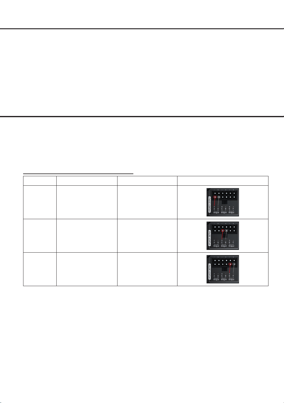
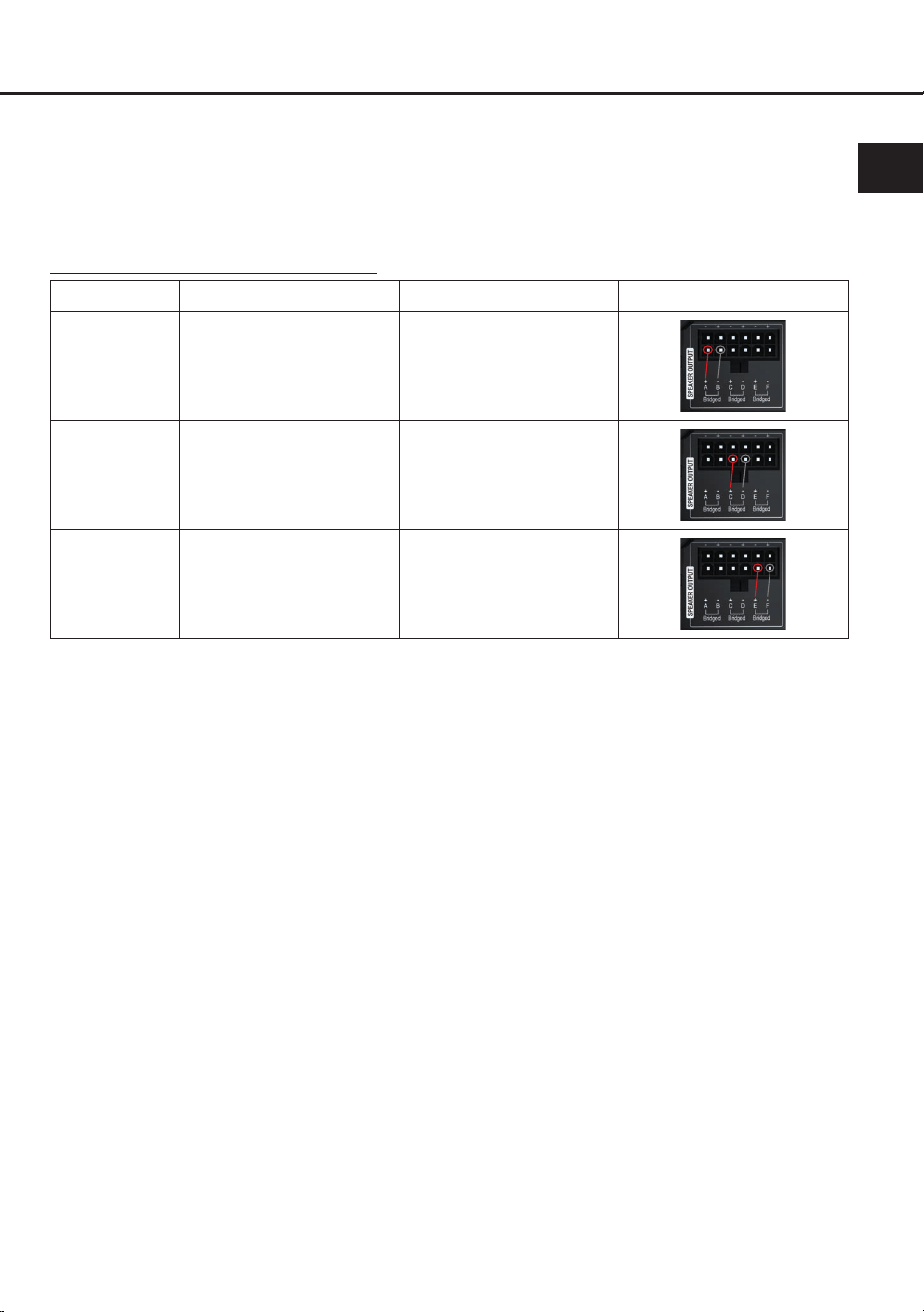
Der AMPLIFY 206 DSP bietet die Möglichkeit die Ausgangskanäle zu brücken.
Durch das Brücken von zwei Ausgangskanälen erhalten Sie einen leistungsstärkeren Ausgangskanal.
Dies ist ideal, wenn Sie einen Lautsprecher mit höherem Leistungsbedarf – z. B. einen Subwoofer –
betreiben möchten. Beim Brücken wird jeweils der positive und negative Ausgang eines Kanalpaares
kombiniert.
Brücken der Lautsprecherausgänge A - F
Übersicht der Kanalpaare und Anschlüsse:
Kanalpaar Anschluss positiv (+)
Anschluss negativ (-)
A/B A + B -
C/D C + D -
E/F E + F -
WICHTIG:
• Stellen Sie sicher, dass die Lautsprecherimpedanz im Brückenbetrieb 4 Ohm nicht unterschreitet
• Verwenden Sie nur die Kanalpaare A/B, C/D & E/F
• Schließen Sie niemals beide positiven oder negativen Ausgänge eines Kanalpaares zusammen

11
de
1. Status LED
Die Status LED zeigt den Betriebszustand des
Verstärkers und dessen Speichers an.
Grün: Verstärker eingeschaltet und betriebs
-
bereit.
Orange: Power Save Modus aktiv.
Rot: Protection Mode aktiv. Dieser kann unter
-
schiedliche Ursachen haben. Der Verstärker ist
mit Schutzschaltungen gegen Über- und Un
-
terspannung sowie Überhitzung ausgestattet.
Prüfen Sie in diesem Fall alle Anschlüsse auf
Fehler, wie z.B. Kurzschlüsse oder fehlerhafte
Verbindungen. Ist die Sicherheitsschaltung
der Temperaturüberwachung aktiv, wird der
Remote-Ausgang sowie die Signalausgabe
abgeschaltet, bis ein sicherer Betrieb wieder
gewährleistet werden kann.
Rot / grün langsam blinkend: Keine Betriebs
-
software auf dem DSP installiert. Verbinden
Sie den Verstärker mit der DSP PC-Tool Soft
-
ware und bestätigen Sie das automatische
Update der Betriebssoftware. Die aktuellste
Version des DSP PC-Tools nden Sie auf
www.audiotec-scher.com.
Rot / grün schnell blinkend: Aktuell ausgewähl
-
ter Sound Setup-Speicherplatz ist leer. Ein
neues DSP Setup muss über die DSP PC-Tool
Software eingespielt werden oder schalten
Sie auf einen Speicherplatz mit vorhandenem
Sound Setup um.
2. SCP (Smart Control Port)
Dieser Multifunktionseingang (Seite 3, Punkt 6)
dient zum Anschluss von HELIX Zubehörpro
-
dukten, wie beispielsweise einer Fernbedie-
nung, mit deren Hilfe diverse Funktionen des
Verstärkers gesteuert werden können.
Die Funktionalität muss je nach Typ der Fern
-
bedienung zuerst im „Remote Control“-Menü
der DSP PC-Tool Software oder an der Fern
-
bedienung selbst konguriert werden.
Achtung: Sofern das Zubehörprodukt keinen
NanoFit Stecker besitzt, ist ein SCP-to-Control
Input Adapter (Art-Nr. M141313) optional bei
Ihrem Fachhändler erhältlich.
3. Clipping LED
In der Regel sind die LEDs aus und leuchten
nur auf, wenn einer der analogen Signalein
-
gänge übersteuert wird.
An (rot): Einer der analogen Signaleingänge
wird übersteuert. Senken Sie die Eingangs
-
empndlichkeit mit Hilfe des zugehörigen
Gain-Reglers ab, bis die LED erlischt. Wie Sie
die Eingangsempndlichkeit absenken, ist auf
Seite 8 unter Punkt 7 nachzulesen.
4. Control Taster
Der AMPLIFY 206 DSP Verstärker bietet 10 in
-
terne Speicherplätze für Sound Setups. Mit Hil-
fe des Control Tasters lässt sich zwischen zwei
Speicherplätzen umschalten. Diese können im
DSP PC-Tool festgelegt werden. Zudem kann
durch langes Drücken des Tasters ein Geräte-
Reset durchgeführt werden.
1. Setup-Wechsel: Taster 1 Sek. drücken.
Werkseitig sind die Speicherbereiche eins und
zwei eingestellt. Der Umschaltvorgang wird
durch einmaliges rotes Blinken der Status LED
angezeigt. Alternativ kann zur Umschaltung
die optionale Fernbedienung URC.3 verwen
-
det werden. Um zwischen allen internen Spei-
cherplätzen umschalten zu können, ist optio-
nales Zubehör, wie z.B. die Fernbedienungen
DIRECTOR und CONDUCTOR notwendig.
2. Geräte-Reset: Taster länger als 5 Sek. ge
-
drückt halten. Durch ein Geräte-Reset wird
der interne Speicher auf die Werkseinstellung
zurückgesetzt! Dies wird durch ein durchge
-
hendes rotes Leuchten und grünes schnelles
Dauerblinken der Status LED angezeigt.
Achtung: Nach dem Resetten des Gerätes
kann die AMPLIFY 206 DSP keine Audio-
signale mehr wiedergeben, bis das Gerät mit
Hilfe des DSP PC-Tools geupdated wurde.
SCP-to-Control Input Adapter
Weitere Funktionen
12
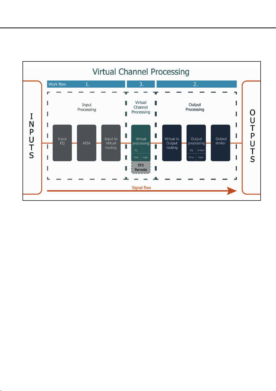
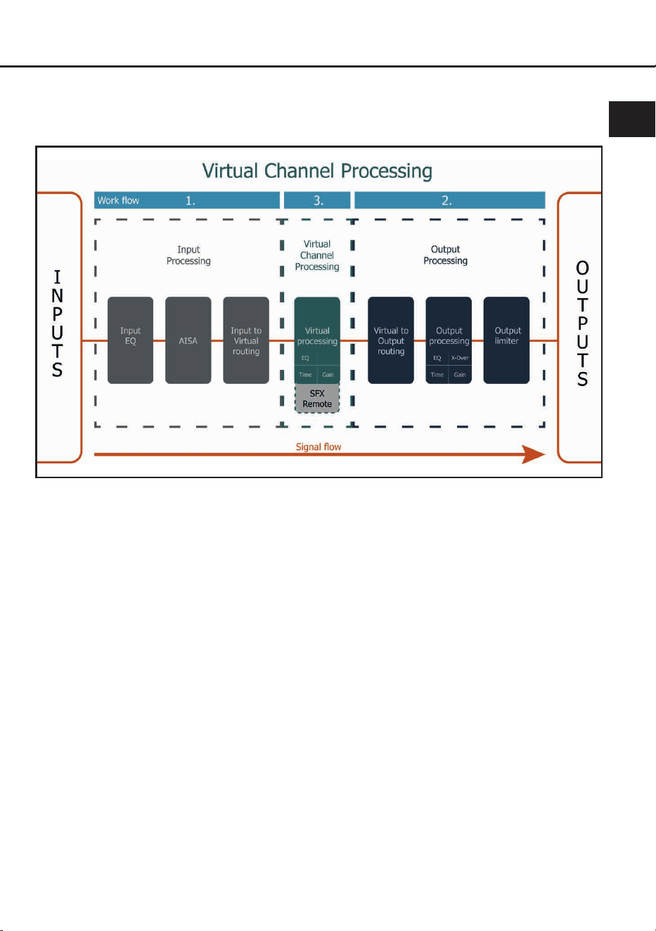
Virtual Channel Processing (VCP)
Das VCP erweitert den Umfang des Gerätes um eine Ebene an prozessierten Kanälen, welche sich
zwischen den Ein- und Ausgängen bendet. Insgesamt stehen acht zusätzliche prozessierte virtuelle
Kanäle und 8 prozessierte Ausgangskanäle zur Verfügung.
Diese virtuelle Kanalebene bietet diverse Vorteile, gerade in komplexen Systemkongurationen.
Die Hauptvorteile dieses Konzeptes sind:
- Ausgangskanalübergreifender Gruppen-Equalizer
- Mehrwege-Konguration der DSP-Soundeekte (SFX)
- Zusätzliche Funktionen wie Rear Attenuation
Weiterführende Informationen zum VCP und dessen Konguration nden Sie in unserer Knowledge
Base auf www.audiotec-scher.com.
Der HELIX AMPLIFY 206 DSP bietet das Virtual Channel Processing (VCP), ein mehrstuges
Signalverarbeitungs-Konzept, welches die perfekte Konguration komplexer Soundsysteme ermöglicht
und somit einzigartige Möglichkeiten des Klangtunings erönet.
13
de
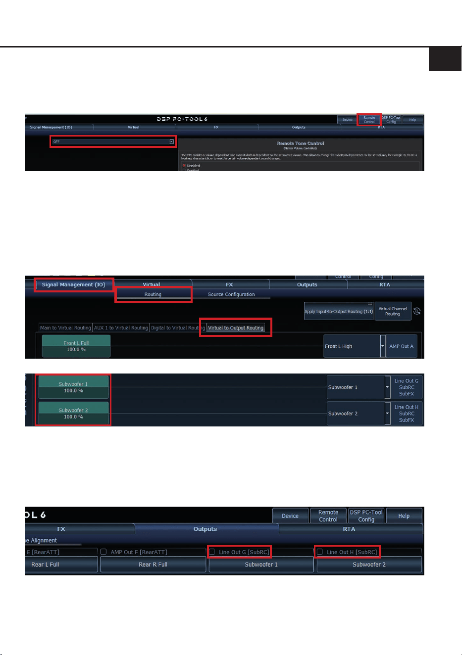
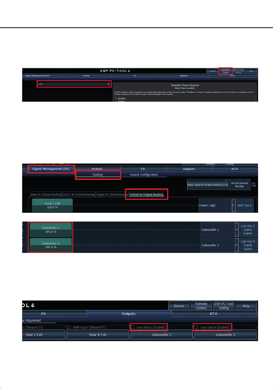
Zur Konguration einer Subwoofer-Fernbedienung müssen im DSP PC-Tool bestimmte Einstellungen
vorgenommen werden.
Zunächst muss die entsprechende Fernbedienung im Tab „Remote Control“ aktiviert und je nach Modell
konguriert werden.
Konguration einer Subwoofer-Fernbedienung
Die Subwoofer-Fernbedienung wirkt auf alle Ausgangskanäle, die im „Virtual to Output Routing“ mit
einem der beiden virtuellen Subwoofer-Signalen versorgt werden („Subwoofer 1“ oder „Subwoofer 2“).
Dies kann jede beliebige Kombination an Ausgangskanälen sein.
Im nachfolgenden Beispiel sind es die Vorverstärker-Ausgänge / Line Out G und H:
Hinweis: Bitte beachten Sie, dass den beiden virtuellen Subwoofer-Signalen „Subwoofer 1“ und / oder
„Subwoofer 2“ zuvor in den anderen Routing-Matrizen ein Eingangssignal zugewiesen werden muss.
Anschließend wird die Subwoofer-Regelung auch im „Outputs“ Menü hinter der Kanalbezeichnung als
[SubRC] angezeigt:

14
ACO Plattform-Features
Neben den einzigartigen DSP-Sound eekten bie-
tet die ACO-Plattform der AMPLIFY 206 DSP zu-
sätzlich eine Vielzahl an System-Features.
Im „Device“-Menü der DSP PC-Tool Software kön-
nen für einige dieser System-Features individuelle
Einstellungen vorgenommen werden.
URC Setup Switch Conguration
Der ACO bietet Speicherplatz für zehn anstelle der
üblichen zwei Sound Setups.
Mit Hilfe einer optional erhältlichen URC Fernbedie
-
nung oder des Control Tasters (Seite 3, Punkt 11)
lässt sich zwischen zwei der zehn Sound-Setup
Speicherplätze umschalten. Diese zwei Speicher
-
plätze können in der „URC Setup Switch Con-
guration“ festgelegt werden. Werkseitig sind die
Speicherbereiche eins und zwei ausgewählt.
Um
zwischen allen internen Speicherplätzen umschal
-
ten zu können, werden die optional erhältlichen
Fernbedienungen DIRECTOR und CONDUCTOR
empfohlen.
Remote Output Conguration
An dieser Stelle kann festgelegt werden, ob der
Remote-Ausgang, der die angeschlossenen
Verstärker ein- bzw. ausschaltet, während eines
Sound-Setup-Wechselvorgangs kurzzeitig deakti-
viert werden soll. Standardmäßig ist dieses Fea-
ture aktiviert (ON).
Turn On & O Delay
Hier kann die Verzögerungzeit, mit welcher der in-
tegrierte DSP ein- und ausgeschaltet werden soll,
festgelegt werden. Werkseitig sind 0,2 Sekunden
eingestellt. Eine Änderung der Verzögerungszeit
sollte nur vorgenommen werden, wenn es bei-
spielsweise zu Störgeräuschen beim Ein- und
Ausschalten des Verstärkers kommt.
Power Save Mode
Diese Funktion ist standardmäßig aktiviert und
dient der Reduzierung der Leistungsaufnahme
des Verstärkers, wenn über einen bestimmten
Zeitraum kein Musiksignal erkannt wird.
Wird der Power Save Mode aktiv, schalten sich
die internen Verstärkerstufen sowie der Remote-
Ausgang (REMOTE Out) automatisch ab. Liegt
anschließend wieder ein Musiksignal an, kehrt
das Gerät innerhalb von ca. 2 Sekunden in den
Normalbetrieb zurück.
Über die DSP PC-Tool Software kann die Funktion
ein- oder ausgeschaltet werden. Ist sie aktiviert,
lässt sich die Abschaltverzögerung im Bereich von
10 bis 600 Sekunden frei einstellen. Werkseitig
beträgt die Verzögerungszeit 60 Sekunden.

15
de
Leistung RMS (≤ 1% THD+N @ 14,4 V)
- @ 4 Ohm ................................................................ 6 x 100 Watt
- @ 2 Ohm ................................................................ 6 x 190 Watt
- gebrückt @ 4 Ohm ................................................. 3 x 380 Watt
Max. Leistung pro Kanal* ......................................... Bis zu 240 Watt RMS @ 2 Ohm
Bis zu 480 Watt RMS @ 4 Ohm gebrückt
Verstärkertechnologie ............................................... Class D
Eingänge .................................................................. 6 x Cinch
oder
6 x Hochpegel-Lautsprechereingang
1 x Optisch SPDIF (12 - 96 kHz)
2 x Remote In
Eingangsempndlichkeit ........................................... Cinch: 1 - 8 Volt
Hochpegel: 2 - 16 Volt
Eingangsimpedanz ................................................... Cinch: 4,8 kOhm
Hochpegel: 9 - 33
Ohm oder 20 kOhm mit ADEP.3
Ausgänge ................................................................. 6 x Lautsprecherausgang
2 x Cinch
1 x Remote Out
Ausgangsspannung Cinch........................................ 8 Volt
Frequenzbereich....................................................... 20 Hz - 22.000 Hz
DSP Auösung ......................................................... 64 Bit
DSP Rechenleistung ................................................ 295 MHz (1,2 Mrd. MAC Operationen/Sek.)
Abtastrate ................................................................. 48 kHz
DSP Typ ................................................................... Audio Signalprozessor
Signalwandler ........................................................... A/D: BurrBrown 24 Bit
D/A: AKM 24 Bit
Signal- / Rauschabstand (A-bewertet)...................... Analogeingang: 99 dB @ Maximalleistung
Digitaleingang: 102 dB @ Maximalleistung
Klirrfaktor (THD @ 1 kHz, 1 W an 4 Ohm) ............... < 0,005 %
Klirrfaktor (THD+N @ 1 kHz, 1 W an 4 Ohm) ........... < 0,02 %
Dämpfungsfaktor ...................................................... 70
Betriebsspannung..................................................... 10,5 - 16 Volt (max. 5 Sek. bis hinab zu 6 Volt)
Leistungsaufnahme .................................................. DC 12 V
93 A max.
Leerlaufstromaufnahme............................................ 1.100 mA
Max. Remote-Ausgangsstrom .................................. 500 mA
Betriebstemperaturbereich ....................................... -40° C bis +70° C
Sicherung ................................................................. 3 x 25 A LP-Mini-Stecksicherung
Zusätzliche Features ................................................ ADEP.3-Schaltkreis, Smart Control Port, Auto
Remote-Schalter, 32 Bit CoProcessor
Abmessungen (H x B x T) ........................................ 40 x 263 x 114 mm
*Ein Kanal ausgesteuert (≤ 10 % THD+N @ 14,4 V)
Technische Daten
16
Die Garantieleistung entspricht der gesetzlichen Regelung. Von der Garantieleistung ausgeschlossen
sind Defekte und Schäden, die durch Überlastung oder unsachgemäße Behandlung entstanden sind.
Eine Rücksendung kann nur nach vorheriger Absprache in der Originalverpackung, einer detaillierten
Fehlerbeschreibung und einem gültigen Kaufbeleg erfolgen. Technische Änderungen, Druckfehler und
Irrtümer vorbehalten!
Für Schäden am Fahrzeug oder Gerätedefekte, hervorgerufen durch Bedienungsfehler des Gerätes,
können wir keine Haftung übernehmen.
Garantiehinweis
Dieses Produkt ist mit einer CE-Kennzeichnung versehen. Damit ist das Gerät für den Be-
trieb in Fahrzeugen innerhalb der Europäischen Union (EU) zertiziert.
Dieses Symbol bedeutet, dass das Produkt nicht über den Hausmüll entsorgt werden darf,
sondern bei einer entsprechenden Sammelstelle zum Recycling abgegeben werden muss.
Befolgen Sie die örtlichen Vorschriften und entsorgen Sie das Produkt niemals mit dem nor-
malen Hausmüll. Die ordnungsgemäße Entsorgung von Altgeräten trägt zur Vermeidung
von Umwelt- und Gesundheitsschäden bei.
Dieses Produkt ist mit einer UKCA-Kennzeichnung versehen. Damit ist das Gerät für den
Betrieb in Fahrzeugen innerhalb des Vereinigten Königreichs zertiziert.
Dieses Produkt ist mit einer EAC-Kennzeichnung versehen. Damit ist das Gerät für den
Betrieb in Fahrzeugen innerhalb der Eurasian Customs Union zertiziert.
Hinweise zur Entsorgung
Regulatorische Hinweise

17
en
General installation instructions for HELIX
components
To prevent damage to the unit and possible injury,
read this manual carefully and follow all installa-
tion instructions. This product has been checked
for proper function prior to shipping and is guaran-
teed against manufacturing defects.
Before starting your installation, disconnect
the battery’s negative terminal to prevent
damage to the unit, re and / or risk of injury.
For a proper performance and to ensure full war-
ranty coverage, we strongly recommend to get this
product installed by an authorized HELIX dealer.
Install your HELIX AMPLIFY 206 DSP in a dry
location with sucient air circulation for proper
cooling of the equipment. The amplier should be
secured to a solid mounting surface using proper
mounting hardware. Before mounting, carefully
examine the area around and behind the pro-
posed installation location to insure that there
are no electrical cables or components, hydraulic
brake lines or any part of the fuel tank located be-
hind the mounting surface. Failure to do so may
result in unpredictable damage to these compo-
nents and possible costly repairs to the vehicle.
General instruction for connecting the HELIX
AMPLIFY 206 DSP amplier
The HELIX AMPLIFY 206 DSP amplier may only
be installed in vehicles which have a 12 Volts neg-
ative terminal connected to the chassis ground.
Any other system could cause damage to the am-
plier and the electrical system of the vehicle.
The positive cable from the battery for the com-
plete system should be provided with a main fuse
at a distance of max. 30 cm from the battery. The
value of the fuse is calculated from the maximum
total current input of the car audio system.
Use only suitable cables with sucient ca-
ble cross section for the connection of HELIX
AMPLIFY 206 DSP. The fuses may only be re-
placed by identically rated fuses (3 x 25 A) to
avoid damage of the amplier.
Prior to installation, plan the wire routing to
avoid any possible damage to the wire harness.
All cabling should be protected against possible
crushing or pinching hazards. Also avoid routing
cables close to potential noise sources such as
electric motors, high power accessories and other
vehicle harnesses.
Congratulations!
General instructions
Dear Customer,
Congratulations on your purchase of this
innovative and high-qual ity HELIX product.
Thanks to more than 35 years of experience in
research and development of audio products the
HELIX AMPLIFY 206 DSP sets new standards in
the range of digital ampliers.
We wish you many hours of enjoyment with your
new HELIX AMPLIFY 206 DSP.
Yours,
AUDIOTEC FISCHER
18
Connectors and control units
1
Signal inputs high- or lowlevel
Page 20, point 2
2
Input type switch
Page 20, point 1
3
Input reference pushbutton
Page 24, point 14
4
Digital optical input
Page 21, point 3
5
Status LED
Page 26, point 1
6
SCP (Smart Control Port)
Page 26, point 2
7
Gain control
Page 22, point 7
8
Clipping LED
Page 26, point 3
9
Auto remote switch
Page 21, point 4
10
Line outputs
Page 23, point 11
11
Control pushbutton
Page 26, point 4
12
USB-C input
Page 22, point 6
13
Speaker outputs
Page 23, point 10
14
Remote in- and output
Page 24, point 13 & page 23, point 12
15
Power & Remote connector
Page 21, point 5
1 32 4 5
13 14 15
7 98 10
1 2 1 2 6
7 8 7 8 11 12
19
en
Hardware conguration
Fig. 1: Overview connection cables
1.1: Connection cable for signal inputs A/B, C/D & E/F (high- & lowlevel)
1.2: Connection cable for speaker outputs A to F
Fig. 2: Removal of cover panel for easier access to connectors and control units
Two strong magnets securely attach the cover panel to the heatsink. To remove it, simply pull the
panel vertically upward. After completing all connections and settings, reattach the panel, ensuring it
is properly aligned and seated without tilting.
CAUTION!
Do not lift the device by
the cover panels to avoid
damage.
1.3: Connection cable line output G & H (Line Out)
20
Congure the HELIX AMPLIFY 206 DSP as fol-
lows
Caution: Carrying out the following steps will
require special tools and technical knowledge. In
order to avoid connection mistakes and / or dam-
age, ask your dealer for assistance if you have any
questions and follow all instructions in this manual
(see page 17). It is recommended that this unit will
be installed by an authorized HELIX dealer.
For better access to the connectors and control
units, we recommend to remove the amplier’s
cover panels, as shown on page 19, g. 2.
1. Adjusting the input voltage range and in-
put impedance (ADEP.3) of the analog in-
puts
ATTENTION: This setting must be made be-
fore initial operation to prevent damage to the
amplier or the connected sound system.
The amplier’s analog input channels can
be driven in pairs with either lowlevel (RCA /
Cinch) or highlevel (speaker wires) signals
from the head unit / radio. To ensure optimal
signal quality, the input voltage range and im-
pedance (ADEP.3) for each channel pair must
be set according to the signal type used, using
the Input Type pushbuttons (page 18, point 2).
RCA: Select this setting when connecting the
amplier´s analog inputs with RCA / Cinch
cables (lowlevel signals) from the head unit /
radio. The input voltage range in this mode is
1 to 8 Volts.
High: Choose this setting if you are using
highlevel signals. This is necessary when the
preconnected device does not have RCA /
Cinch outputs, such as factory car radios or
OEM headunits. In this mode, the signal is
transmitted via the speaker wires, and the in-
put voltage range is 2 to 16 Volts.
2. Connecting the signal inputs (high- or low-
level)
The signal inputs of the amplier (A/B, C/D
and E/F; page 18, point 1) can be connected
to the signal source using the supplied con-
nection cables (page 19, g. 1, point 1.1).
Each input can be assigned to any output us-
ing the DSP PC-Tool software.
We recommend the following channel assign-
ment if a common car radio will be connected
to the amplier:
Channel A = Front left
Channel B = Front right
Channel C = Rear left
Channel D = Rear right
Actually it is not mandatory to use all signal
inputs. If only two channels will be connected
we recommend to use the channels A and B.
Make sure that the polarity is correct. If one
or more connections have reversed polarity it
may aect the performance of the amplier.
The input sensitivity of each channel pair can
be optimally adjusted to the signal source
using the respective gain control (page 18,
point 7).
a. Connecting pre-amplier / low level- /
Cinch/RCA signals
The RCA /Cinch outputs of the signal
source (e.g. aftermarket radio) can be con-
nected directly to the signal inputs A/B, C/D
or E/F using the supplied connection cables
(page 19, g. 1, point 1.1). The automatic
turn-on circuit does not work when using
the lowlevel signals. In this case one of the
remote inputs (REM or REMOTE In) must
be connected to activate the amplier.
b. Connecting highlevel signal (speaker
wires)
If your signal source (e.g., OEM radio or
OEM amplier) does not have RCA outputs,
you can connect the speaker outputs to the
amplier’s analog signal inputs. To do this,
cut o the RCA /Cinch connectors from the
supplied connection cables and use them
as adopters for the speaker wires.
Connect the signal source to the A/B, C/D
and / or E/F inputs of the amplier using the
modied connection cables.
The amplier is equipped with our propri-
etary ADEP.3 circuit (Advanced Diagnostics
Error Protection 3rd generation) which en-
sures that the car radio detects the amplier
Hardware conguration

21
en
as a speaker and thus neither any function
of the radio (e.g. fader) will be deactivated
nor any error log in the CPU of the car will
be created.
When using highlevel signals, neither of the
remote inputs (REM and / or REMOTE In)
needs to be connected, as the amplier will
automatically turn on once a loudspeaker
signal is applied.
Attention: Only use the supplied connec-
tion cables for installation (page 19, g.1,
point 1.1).
Note: The amplier can operate with either
lowlevel (RCA / Cinch) or highlevel signals.
Simultaneous use of both signal types on one
channel pair may cause damage to the signal
source.
Example: Channel pair A/B is operated with
highlevel signals, while channel pairs C/D and
E/F are supplied with lowlevel signals.
3. Connecting a digital signal source in
SPDIF format
If you have a signal source with a digi tal opti-
cal output you can connect it to the amplier
using the appropriate input (Optical Input).
The sampling rate must be between 12 and
96 kHz. The input signal is automatically
adapted to the internal sample rate.
In standard conguration the manual activa-
tion via an optional remote control is cong-
ured. Alternatively you can activate the au-
tomatic turn-on feature in the DSP PC-Tool
software under the “Signal Management (IO)”
tab in the “Source Conguration” sub-menu.
The automatic turn-on circuit does not work
when the digital input is used. Therefore it is
mandatory to connect one of the remote in-
puts (REM or REMOTE In).
Important: The signal of a digital audio
source often does not contain any informa-
tion about the volume level. Keep in mind that
this will lead to full level on the outputs of the
HELIX AMPLIFY 206 DSP and your connect-
ed ampliers. This may cause severe damage
to your speakers. We strongly recommend to
use an optional remote control for adjusting
the volume level of the digital signal input!
Note: The amplier can only handle uncom-
pressed digital stereo signals in PCM for-
mat with a sample rate between 12 kHz and
96 kHz.
4. Conguration of the remote input
This setting is only required when connecting
the signal source using highlevel signals.
The amplier will turn on automatically when
driven by a highlevel signal or when a signal
is applied to one of the remote input terminals
(REM / REMOTE In). The auto remote switch
(page 18, point 9) allows to deactivate the
automatic turn-on feature. The feature should
be deactivated if there are e.g. noises while
switching on / o the amplier.
On: Activation via highlevel signal is en-
abled (by default).
O: Activation via highlevel signal is dis-
abled.
Note: If the automatic turn-on function is de-
activated it is mandatory to use one of the
remote input terminals to power up the am-
plier! The highlevel signal will be ignored in
this case.
5. Connection to power supply & remote
ATTENTION: Make sure to disconnect
the battery before installing the HELIX
AMPLIFY 206 DSP!
Make sure of correct polarity.
+12 V: Connector for the positive cable.
Connect the +12 V power cable to the positive
terminal of the battery. The positive wire from
the battery to the ampliers power terminal
needs to have an inline fuse at a distance of
no more than 12 inches (30 cm) from the bat-
tery. The value of the fuse is calculated from
the maximum total current input of the whole
car audio system (206 DSP = max. 93 A at
12 V power supply). If your power wires are
short (less than 1 m / 40”) then a wire gauge of
10 mm² / AWG 8 will be sucient. In all other
cases we strongly recommend gauges of 16 -
25 mm² / AWG 6 – 4!
GND: Connector for the ground cable. The
ground wire should be connected to a com-
mon ground reference point (this is located
where the negative terminal of the battery is
grounded to the metal body of the vehicle) or
to a prepared metal location on the vehicle
22
Hardware conguration
chassis, i.e., an area cleaned of all paint resi-
dues. The cable should have the same gauge
as the +12 V wire. Inadequate grounding
causes audible interference and malfunctions.
REM: The remote input is used to switch on
and o the amplier if lowlevel signals or the
digital input are / is used.
If the connected highlevel signal source does
not activate the “automatic turn-on” function
or the amplier is to be deliberately switched
on and o only via a remote signal, this input
must be assigned. The remote wire should be
connected to the remote output / automatic
antenna (aerial positive) output of the head
unit / car radio.
Alternatively, you may use the additional re-
mote input (REMOTE In; page 18, point 14).
Both inputs are internally linked and provide
the same function. This input does not need to
be assigned if a highlevel signal is used.
We do not recommend controlling the remote
input via the ignition switch to avoid pop noise
during turn on / o.
To deactivate the “automatic turn-on” function
read the description on page 21 in point 4
“Conguration of the remote input”.
6. Connecting the PC & rst start-up
The USB-C input (page 18, point 12) enables
the connection of the amplier to a personal
computer and its free conguration with our
DSP PC-Tool software using the provided
USB cable.
Please note: It is not possible to connect any
USB storage devices.
Before you connect the AMPLIFY 206 DSP
to a computer for the rst time, download
the latest DSP PC-Tool software (at least
version 6) from our homepage. The software
and a comprehensive knowledge base can be
found at www.audiotec-scher.com.
It is advisable to check regularly for software
updates so that the device is always up to
date. We strongly recommend to carefully
read the DSP PC-Tool knowledge base before
using the software for the rst time in order to
avoid any complications and failures.
Important: Make sure that the amplier is not
connected to your computer before the soft-
ware and USB driver are installed!
In the following the most important steps how
to connect and the rst start-up are described:
1. Download the latest version of the DSP
PC-Tool software (available on our web-
site www.audiotec-scher.com) and in-
stall it on your computer.
2. Connect the amplier to your computer us-
ing the USB cable that is included in deliv-
ery. If you have to bridge longer distances
please use an active USB extension cable
with integrated repeater.
3. First turn on the amplier and then start the
software. The operating software will be
updated automatically to the latest version
if it is not up-to-date.
7. Adjustment of the input sensitivity of the
analog signal inputs
ATTENTION: It is mandatory to properly
adapt the input sensitivity of the AMPLIFY
206 DSP to the signal source to achieve the
best possible signal quality and avoid damage
to the amplier. It is also mandatory to adjust
the input voltage range and the input imped-
ance (ADEP.3) of the signal inputs to the out-
put voltage of your signal source (page 20,
point 1).
The input sensitivity of each channel pair (A/B,
C/D and E/F) can be optimally adapted to the
signal source using the respective gain control
(page 18, point 7).
These controls are not volume controls; they
are solely for adjusting the amplier´s gain.
The gain control ranges are:
Highlevel: 2 - 16 Volts
RCA / Cinch: 1 - 8 Volts
The three Clipping LEDs (page 18, point 8)
serve as monitoring tool.
Attention: Do not connect any speakers to
the outputs of the amplier during this setup
and switch o any connected ampliers.

23
en
To adjust the input sensitivity, please follow
the steps below for each channel pair (A/B,
C/D and E/F) in sequence:
1. Turn on the amplier.
2. Adjust the volume of your radio to approx.
90 % of the maximum volume and play
back a suitable test signal – ideally our spe-
cially developed “IGS – Input Gain Setup”
signal, which can be found under “Audio
Test Tracks” in the DSP PC-Tool or down-
loaded from www.audiotec-scher.com.
3. Normally, the Clipping LED is o and only
lights up if one of the analog inputs is over-
driven.
Now increase the input sensitivity by turn-
ing the Gain control clockwise until the Clip-
ping LED lights up.
4. Now turn the control counterclockwise until
the Clipping LED turns o again.
5. Repeat this process for each channel pair.
8. Conguration of the internal DSP
IMPORTANT: The general DSP settings
should be conducted with the DSP PC-Tool
software before using the amplier for the
rst time. Now you are able to congure your
AMPLIFY 206 DSP with our intuitive DSP PC-
Tool software. Useful hints for the correct set-
ting can be found in our knowledge base at
www.audiotec-scher.com.
Caution: We highly recommend to set the
volume of your car radio to minimum position
during rst start-up. Additionally no devices
should be connected to the amplier. Espe-
cially if the AMPLIFY 206 DSP will be used
in fully active applications, a wrong setup can
destroy your speakers right away.
9. Optional: Analyzing the input signal
When using highlevel signals at the analog
signal inputs, we recommend analyzing the in-
put signal with the Advanced Input Signal An-
alyzer (AISA) in the DSP PC-Tool. This helps
detect and correct factory-set equalization,
time alignment, or allpass lters if present.
Information on the AISA can be found in the
extensive Knowledge Base on our website
www.audiotec-scher.com.
10. Connecting the loudspeaker outputs
The loudspeaker outputs can be connect-
ed directly to the wires of the loudspeakers.
Never connect any of the loudspeaker cables
with the chassis ground as this will damage
your amplier and your speakers. Ensure that
the loudspeakers are correctly connected (in
phase), i.e., plus to plus and minus to minus.
Exchanging plus and minus causes a total
loss of bass reproduction. The plus pole is in-
dicated on most speakers.
The impedance of each channel must not be
less than 2 Ohms (4 Ohms in bridged mode),
otherwise the amplier protection will be ac-
tivated.
Attention: Solely use the supplied connection
cable with the 12-pin plug and ying leads
for connecting the speaker outputs (page 19,
g. 1, point 1.2). Connecting wires of unused
speaker outputs must be insulated against
short circuits.
11.
Optional: Connecting the line outputs G & H
The two pre-amplier outputs (LINE OUT G &
H) can now be connected to the RCA / Cinch
inputs of the external ampliers using appro-
priate cables (RCA / Cinch cables).
The outputs provide a maximum output volt-
age of 8 Volts RMS. When using one of these
outputs, it is essential to use the remote out-
put (REMOTE OUT) to switch on an addition-
ally connected amplier, as otherwise interfer-
ence noise may occur.
Attention: Solely use the supplied connec-
tion cable for connection (page 19, g. 1,
point 1.3)
12. Optional: Connecting the remote output
The remote output (page 18, point 14) is used
for turning on / o ampliers that are con-
nected to the line outputs of the AMPLIFY
206 DSP. Therefore connect the remote out-
put of the AMPLIFY 206 DSP to the remote in-
put of your ampliers to switch it on and o via
the internal DSP without interfering signals.
The remote output is activated automatically
as soon as the booting process of the DSP
is completed. Additionally this output will be
turned o during the “Power Save Mode” or a

24
Hardware conguration
software update process.
Important: Never use a dierent signal than
the remote output of the AMPLIFY 206 DSP to
activate a connected amplier!
13. Optional
: Connecting the additional re-
mote input
The AMPLIFY 206 DSP provides, in addition
to the remote input located at the power sup-
ply connections (REM; page 18, point 15),
an additional remote input (REMOTE In;
page 18, point 14).
Both inputs are internally linked and serve
the same function. Therefore choose the in-
put that is most accessible for your installa-
tion. For further details on the function of the
remote input, please refer to section 5 “Con-
nection to power supply & remote” on page 21
under “REM”.
14. Optional: Conguration of the input refer-
ence
In some cases, it may be necessary to adjust
the signal ground of the signal inputs.
This can be done using the input reference
pushbutton (page 18, point 3).
Float: In this switch position, the signal ground
is separated from the vehicle’s ground by a
dierential amplier. This is usually the best
setting in most vehicles to prevent interfer-
ence noise, e.g. from the alternator.
GND: The signal ground is tied together with
the vehicle’s ground. This setting should be
selected if noise occurs in the “Float” position.
15. Sound tuning
Now you can create your sound setup.
Information about sound tuning can be
found in our extensive knowledge base at
www.audiotec-scher.com or contact your
local HELIX dealer.
25
en
Bridging speaker outputs A - F
The AMPLIFY 206 DSP allows the output channels to be bridged. By bridging two output channels,
you create a more powerful single channel. This is ideal for driving a speaker with higher power re-
quirements – for example, a subwoofer. When bridging, the positive output of the rst channel and the
negative output of the second channel of a channel pair are combined.
Channel pair and connection overview:
Channel pair Positive connection (+)
Negative connection (-)
A/B A + B -
C/D C + D -
E/F E + F -
IMPORTANT:
• Ensure that the speaker impedance in bridged mode is not less than 4 Ohms
• Use only the channel pairs A/B, C/D & E/F
• Never connect both positive or both negative outputs of a channel pair together

26
1. Status LED
The Status LED indicates the operating mode
of the amplier and of its memory.
Green: Amplier is ready for operation.
Orange: Power Save Mode is active.
Red: Protection Mode is active. This may
have dierent root causes. The HELIX
AMPLIFY 206 DSP is equipped with protec-
tion circuits against over- and undervoltage
as well as overheating. Please check for con-
necting failures such as short-circuits or other
wrong connections. If the amplier is over-
heated the internal temperature protection
switches o the remote and signal output until
it reaches a safe temperature level again.
Red / green slow ashing: No operating soft-
ware installed. Connect the amplier to the
DSP PC-Tool software and conrm the au-
tomatic update of the operating system. You
will nd the latest version of the DSP PC-Tool
software at www.audiotec-scher.com.
Red / green fast ashing: The currently se-
lected sound setup memory is empty. A new
setup has to be loaded via the DSP PC-Tool
software or switch to a memory position with
existing sound setup.
2. SCP (Smart Control Port)
This multi-functional input (page 18, point 6)
is used to connect HELIX accessory products,
such as a remote control, which allows the
user to adjust several features of the ampli-
er. Depending on the type of remote control,
at rst its functionality has to be dened in the
“ Remote Control” menu of the DSP PC-Tool
software.
Attention: If the accessory product does not
have a NanoFit connector, a SCP-to-Control
Input adaptor (Art-Nr. M141313) is optionally
available from your specialist dealer.
3. Clipping LED
Normally, the Clipping LEDs are o and only
light up if one of the analog inputs is overdriv
-
en.
On (red): One of the analog signal inputs is
overdriven. Reduce the input sensitivity using
the respective Gain control until the LED goes
out. Instructions on how to reduce the input
sensitivity are described on page 22, point 7.
4. Control pushbutton
The AMPLIFY 206 DSP provides 10 internal
memory locations for sound setups. The Con-
trol pushbutton allows the user to switch be-
tween two memory positions. These can be
dened in the DSP PC-Tool. In addition a de-
vice reset can be made by pressing the button
for a longer period.
1. Setup switch: Press Control pushbutton for
1 second. The memory locations one and two
are dened by default. Switching is indicated
by a single red ash of the Status LED. Al-
ternatively, the optional URC.3 remote control
can be used for switching. To switch between
all internal memory locations, optional acces-
sories like the DIRECTOR display remote
control or CONDUCTOR are required.
2. Device reset: Press pushbutton for ve
seconds. This completely erases the internal
memory and is indicated by a continuous red
glowing and constant green ashing of the
Status LED.
Attention: After erasing the setups from
memory the AMPLIFY 206 DSP will not re-
produce any audio output until the device is
updated via the DSP PC-Tool software.
SCP-to-Control Input adaptor
Additional functions
27
en
Virtual Channel Processing (VCP)
The VCP extends the scope of the device by an additional layer of processed channels, which is
located between the inputs and outputs. A total of eight additional processed virtual channels and eight
processed output channels are available.
This virtual channel layer oers several advantages, especially in complex system congurations.
The main advantages of this concept are:
- Cross-channel group equalizers that aect several output channels simultaneously
- Multi-way speaker conguration of DSP sound eects (SFX)
- Additional features such as Rear Attenuation
For further information on the VCP and its conguration, please refer to our Knowledge Base at
www.audiotec-scher.com.
The HELIX AMPLIFY 206 DSP oers Virtual Channel Processing (VCP), a multi-stage signal processing
concept that enables the perfect conguration of complex sound systems, opening up completely new
possibilities for sound tuning.
28
Conguration of a subwoofer remote control
In order to congure a subwoofer remote control, specic settings have to be made in the DSP PC-Tool.
First, the appropriate remote control must be activated in the “Remote Control” tab and then congured,
depending on the model.
The subwoofer remote control is tied to the output channels that are supplied with one of the two virtual
subwoofer signals (“Subwoofer 1” or “Subwoofer 2”) in the “Virtual to Output Routing” matrix. This can
be any combination of output channels.
In the following example these are the pre-amplier outputs / Line Out G and H:
Note: Please note that an input signal must be assigned to the two virtual subwoofer signals
“ Subwoofer 1” and / or “Subwoofer 2” in the other routing matrices.
The subwoofer control is then also displayed in the “Outputs” menu next to the name of the channel as
[SubRC]:

29
en
ACO platform features
Beside the unique DSP sound eects the
AMPLIFY 206 DSP provides a bunch of system
and DSP features.
In the “Device” menu of the DSP PC-Tool soft-
ware individual settings can be made for several
of these system features.
URC Setup Switch Conguration
The ACO provides ten internal memory locations
for sound setups instead of the common two.
By using an optional URC remote control or the
Control pushbutton (page 18, point 11) it is pos
-
sible to toggle between two of the ten memory
locations. These two memory locations can be
determined in the “URC Setup Switch Congu
-
ration”. The memory locations one and two are
preassigned by default. To switch between all in
-
ternal memory locations, the optionally available
remote controls DIRECTOR and CONDUCTOR
are recommended.
Remote Output Conguration
This function controls if the remote output (which
switches on and o the connected ampliers) will
be temporarily deactivated during a sound setup
switch. This function is activated (ON) by default.
Turn On & O Delay
This function allows to determine the delay time
with which the integrated DSP is switched on and
o. The factory setting is 0.2 seconds. The delay
time should only be modied if there are e.g. nois-
es while switching on / o the amplier.
Power Save Mode
This function is activated by default and is used
to reduce the power consumption of the amplier
if no music signal is detected for a certain period
of time.
When power save mode is active, the internal
amplier stages and the remote output (REMOTE
Out) are automatically switched o. Once a mu-
sic signal is detected again, the device returns to
normal operation within approximately 2 seconds.
The function can be switched on or o using
the DSP PC-Tool software. If it is activated, the
switch-o delay can be freely set in the range from
10 to 600 seconds. The default delay time is 60
seconds.

30
Technical data
Power RMS (≤ 1% THD+N @ 14.4 V)
- @ 4 Ohms .............................................................6 x 100 Watts
- @ 2 Ohms .............................................................6 x 190 Watts
- bridged @ 4 Ohms ................................................3 x 380 Watts
Max. output power per channel* .............................. Up to 240 Watts RMS @ 2 Ohms
Up to 480 Watts RMS @ 4 Ohms bridged
Amplier technology ................................................Class D
Inputs ....................................................................... 6 x RCA / Cinch
or
6 x Highlevel speaker input
1 x Optical SPDIF (12 - 96 kHz)
2 x Remote In
Input sensitivity ........................................................ RCA / Cinch: 1 - 8 Volts
Highlevel: 2 - 16 Volts
Input impedance ...................................................... RCA / Cinch: 4.8 kOhms
Highlevel: 9 - 33
Ohms or 20 kOhms with ADEP.3
Outputs .................................................................... 6 x Speaker output
2 x RCA / Cinch
1 x Remote Out
Output voltage RCA / Cinch.....................................8 Volts
Frequency range .....................................................20 Hz - 22,000 Hz
DSP resolution .........................................................64 Bit
DSP power ..............................................................295 MHz (1.2 billion MAC operations/sec.)
Sampling rate ..........................................................48 kHz
DSP type .................................................................Audio signal processor
Signal converters ..................................................... A/D: BurrBrown 24 Bit
D/A: AKM 24 Bit
Signal-to-noise ratio (A-weighted) ........................... Analog input: 99 dB @ full power
Digital input: 102 dB @ full power
Distortion (THD @ 1 kHz, 1 W into 4 Ohms) ........... < 0.005 %
Distortion (THD+N @ 1 kHz, 1 W into 4 Ohms) ......< 0.02 %
Damping factor ........................................................70
Operating voltage ....................................................10.5 - 16 Volts (max. 5 sec. down to 6 Volts)
Power rating ............................................................DC 12 V
93 A max.
Idle current...............................................................1,100 mA
Max. remote output current .....................................500 mA
Operating temperature range ..................................-40° C to +70° C
Fuse.........................................................................3 x 25 A LP-Mini-fuse (APS)
Additional features ................................................... ADEP.3 circuit, Smart Control Port, Auto remote
switch, 32 Bit CoProcessor
Dimensions (H x W x D) ..........................................40 x 263 x 114 mm / 1.58 x 10.35 x 4.49”
*One channel driven (≤ 10 % THD+N @ 14.4 V)
31
en
The warranty service is based on the statutory regulations. Defects and damage caused by overload
or improper handling are excluded from the warranty service. Any return can only take place following
prior consultation, in the original packaging together with a detailed description of the error and a valid
proof of purchase.
Technical modications, misprints and errors excepted! For damages on the vehicle and the device,
caused by handling errors of the device, we can’t assume liability.
Warranty disclaimer
This product has been issued a CE marking. This means that the device is certied for use
in vehicles within the European Union (EU).
This symbol means the product must not be discarded as household waste, and should
be delivered to an appropriate collection facility for recycling. Follow local rules and never
dispose of the product with normal household waste. Correct disposal of old products helps
prevent negative consequences for the environment and human health.
This product has been issued an UKCA marking. This means that the device is certied for
use in vehicles within the United Kingdom.
This product has been issued an EAC marking. This means that the device is certied for
use in vehicles within the Eurasian Customs Union.
Correct disposal of this product
Regular notes

Audiotec Fischer GmbH
Hünegräben 26 - 28 · 57392 Schmallenberg · Germany
Tel.: +49 2972 9788 0 · Fax: +49 2972 9788 88
E-mail: helix@audiotec-scher.com · Internet: www.audiotec-scher.com
Made in China