Key Steps to a Successful Installation
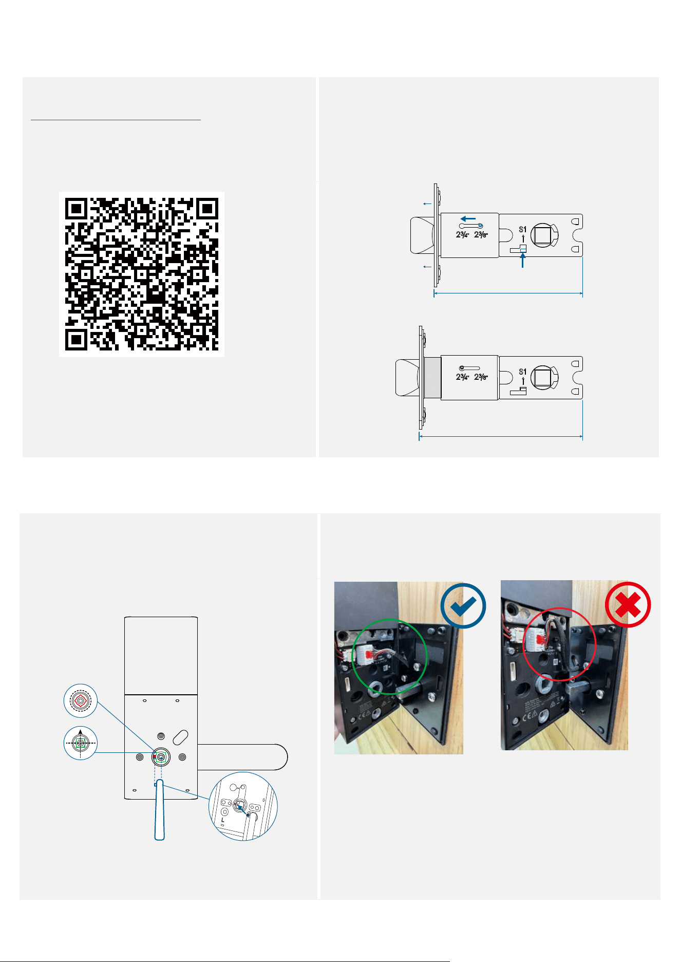
Before Proceeding
• View the installation video before you proceed.
https://youtu.be/9niPWO5002w
• If the backset of your door is 2¾ in (70 mm), you will need to
extend the latch.
Push the S1 tab upward and hold it (1), press down the knob
(2), slide the knob toward the 2¾ position, and pull out the
faceplate (3).
• Make sure that the S1 tab is ALWAYS upward when
extending the latch.
2 ⅜ in (60 mm)
2 ¾ in (70 mm)
❷❸
❶
During Installation
• Thoroughly check that the spindle is securely
installed and cannot be pulled out, otherwise
the lock might fail. (Refer to Step 3 for spindle
installation)
• Make sure the cable is tucked into the cavity on the back
of the interior assembly.
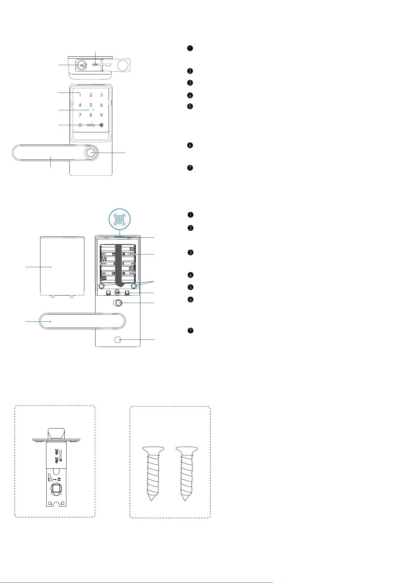
At a Glance
Exterior Assembly
⑥
⑤
⑦
①
②
③
④
USB-C Port
• Charges the lock in emergency situations.
Keyway
Keypad
NFC Reader
Status Light and Lock / Unlock Button
• Blue: Door Unlocked
• Orange: Door Locked
• Red: Abnormal State
Handle
• Adjust the handle's direction to the left or right as needed.
Fingerprint Scanner
Interior Assembly
⑥
⑤
⑤
⑦
①
②
③
④
Battery Cover
Handle
• Adjust the handle's direction to the left or right as needed.
QR Code
• Scan to add Smart Lever Lock C33 in the app.
Battery Compartment
Screw Hole
Setup Button
• Press for 2 seconds to put Smart Lever Lock in paring mode.
• Press for 10 seconds to reset Smart Lever Lock.
Privacy Button
• Green: Unlock the door from inside or outside.
• Red: Unlock the door from inside only.
What’s in the Box
Step 2
A
B
Latch Latch Screws
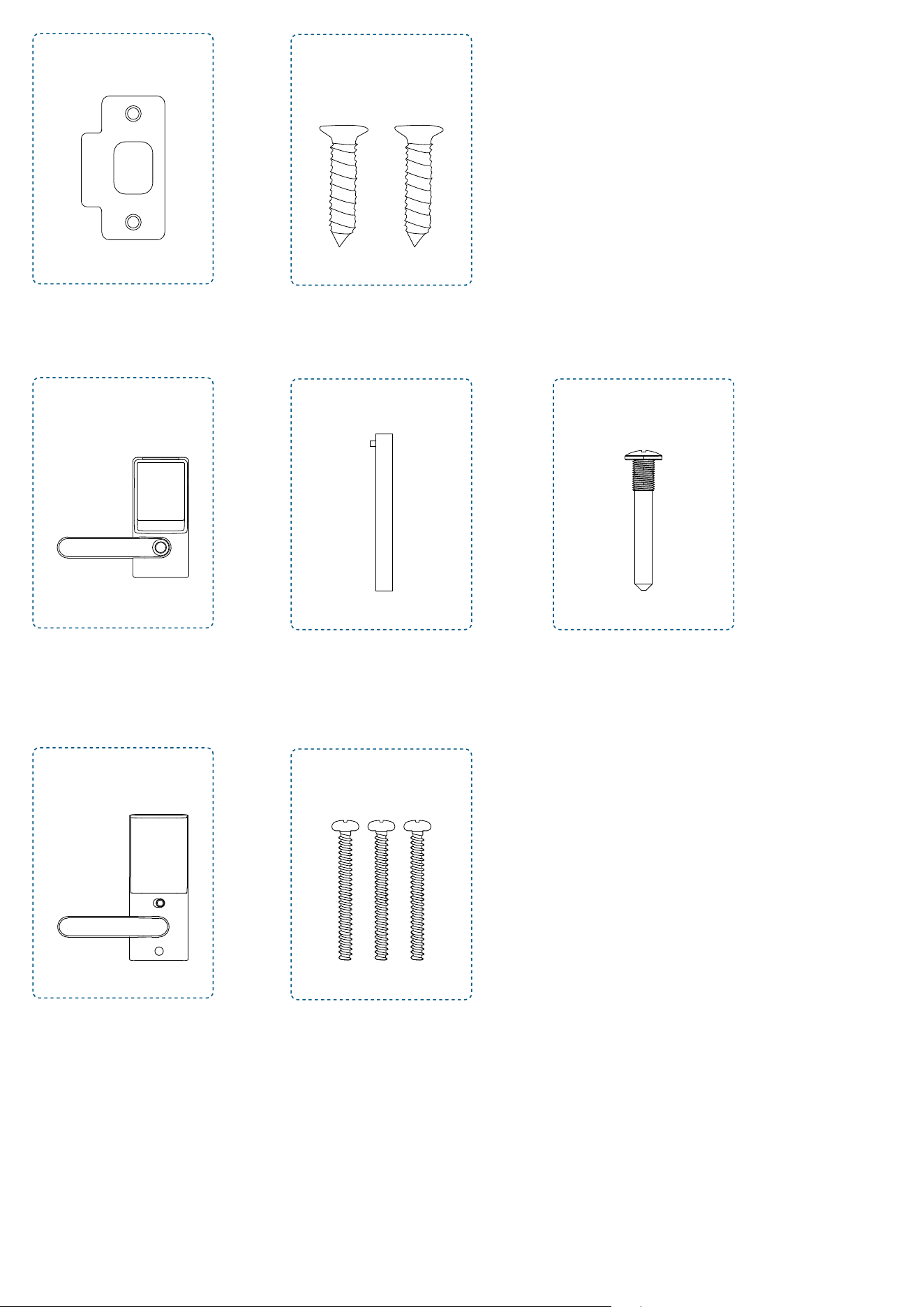
C
D
Strike Plate Strike Screws
Step 3
E
F
G
Exterior Assembly
Spindle
(Pre-installed in exterior assembly)
Exterior Handle Screw
Step 4
H
I
Interior Assembly Mounting Plate Screws
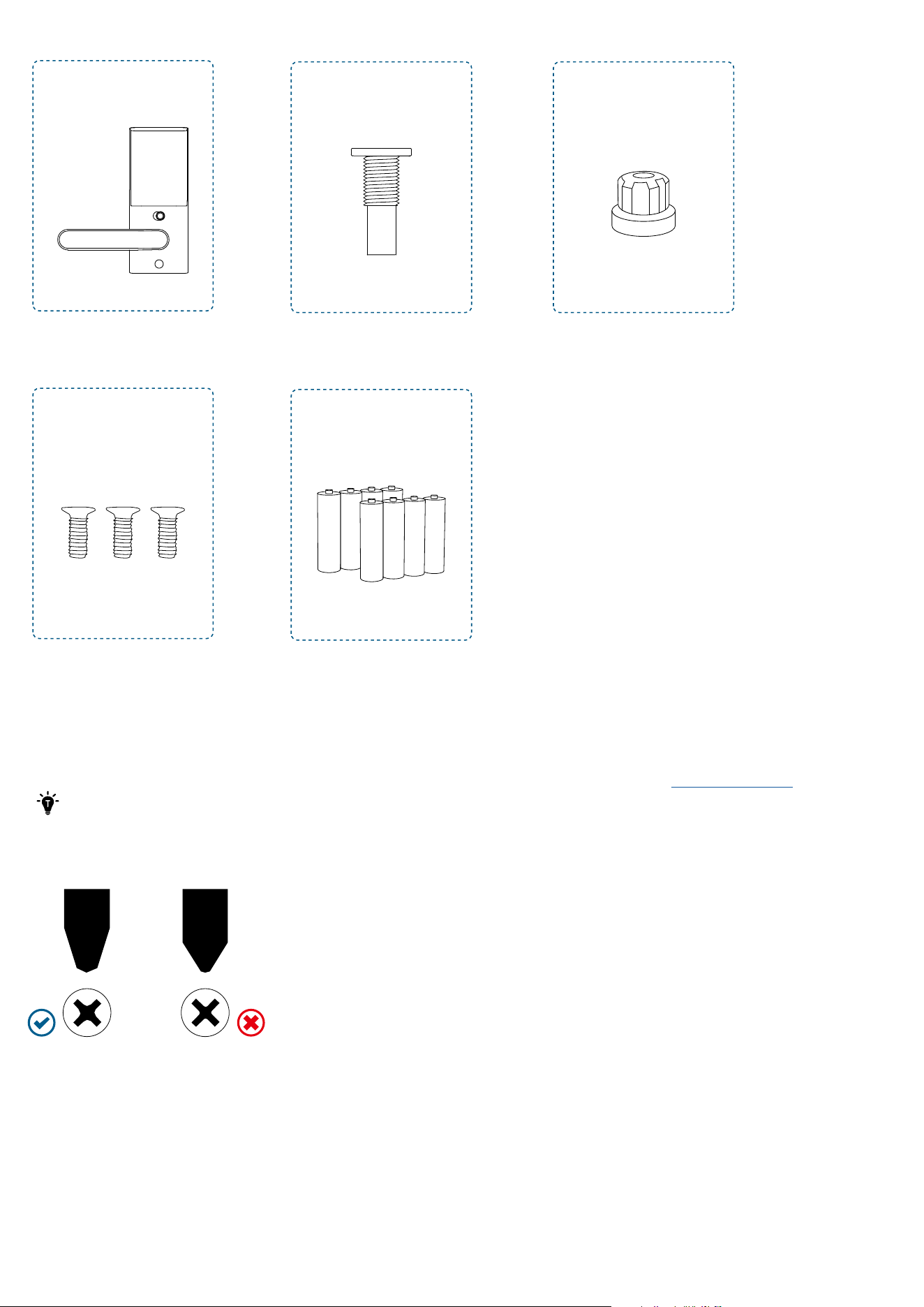
Step 5
H
L
J
M
K
Interior Assembly
Interior Assembly Screws
Interior Handle Screw
Batteries
Silicone Plug
Installing Smart Lever Lock
Installation generally takes less than 20 minutes. If you have any questions or concerns, visit
support.eufy.com for assistance.
Keep the door open during installation. Do not close the door until the batteries are inserted.
What You Need
Prepare a standard Phillips screwdriver before installation. The included screws are Phillips screws.
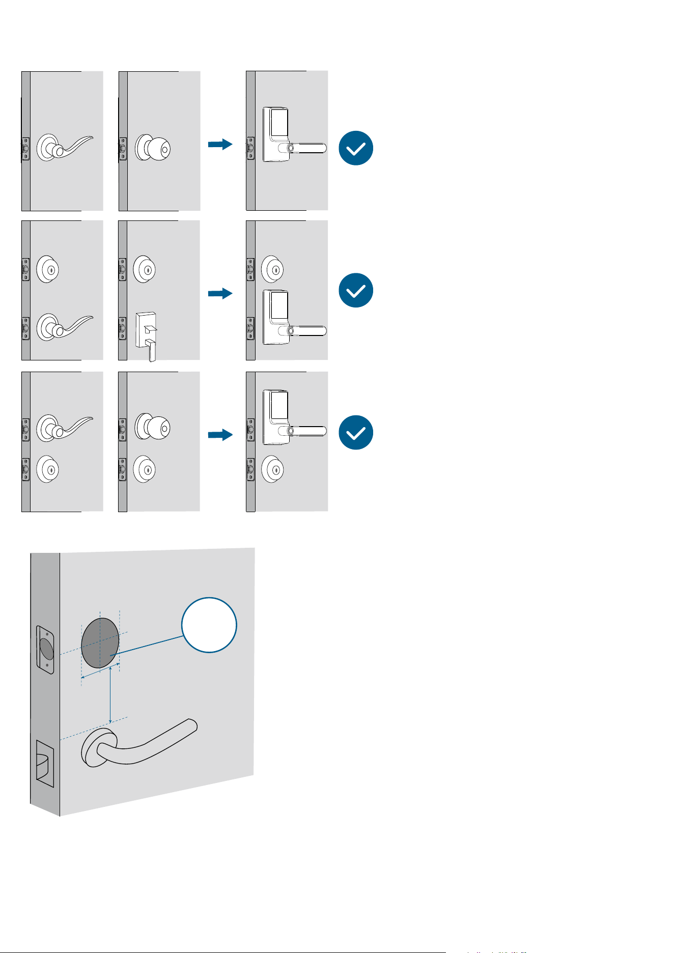
Step 1. Prepare the Door
1. Decide the installation position of the Smart Lever Lock based on the location of the existing lock (if any).
2. To avoid installation issues, remove the existing lock or keep it at least 1¾ in (45 mm) below the Smart Lever Lock.
Minimum
Distance
1¾ in (45 mm)
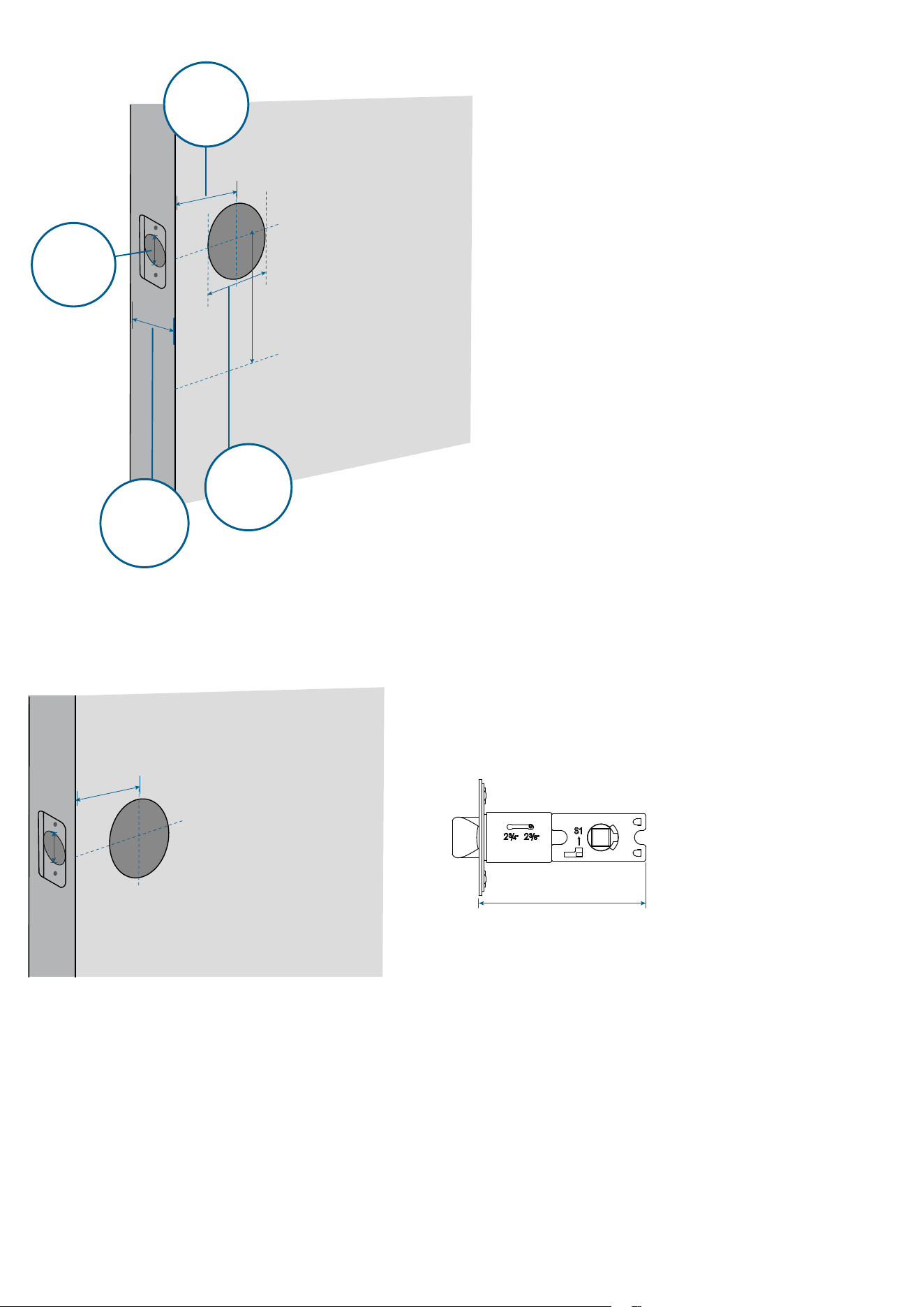
3. Check if your door has holes as illustrated below. If not, use the template and drill holes in your door.
Backset
2⅜ in (60 mm) or
2¾ in (70 mm)
Door Hole
Diameter
1 in (25.4mm)
Cross Bore
Diameter
2 ⅛ in (54 mm)
Door Thickness
1⅜ in - 2
¹¹
⁄
64
(35mm - 55mm)
Step 2. Install Latch & Strike Plate
1. Check your door to see if the latch requires adjustment.
If the backset is 2 ⅜ in (60 mm), use the provided latch to install.
2 ⅜ in (60 mm)
2 ⅜ in (60 mm)
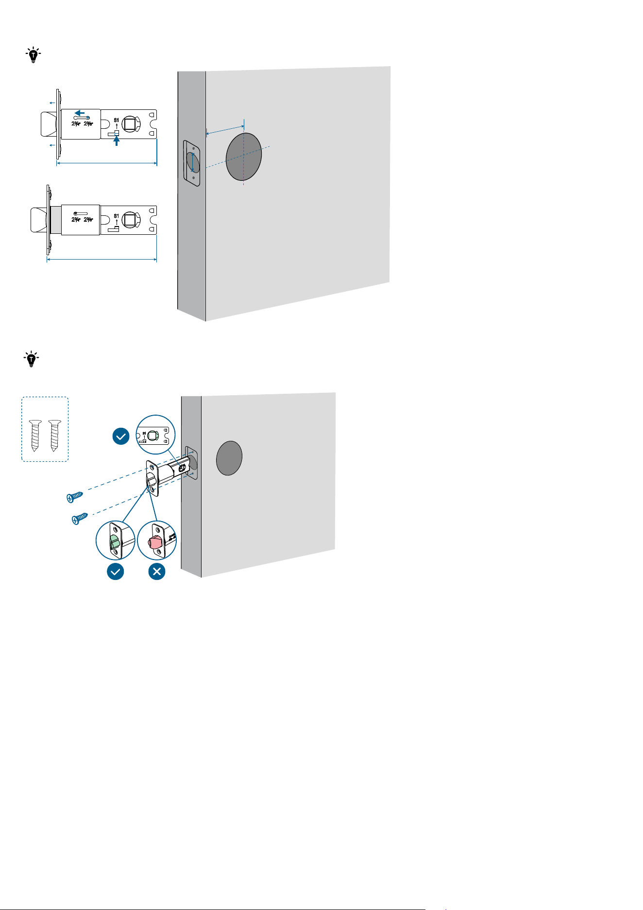
If the backset is 2¾ in (70 mm), you will need to extend the latch. Push the S1 tab upward and hold it (1), press down the
knob (2), slide the knob toward the 2¾ position, and pull out the faceplate (3).
Make sure that the S1 tab is ALWAYS upward when extending the latch.
2 ⅜ in (60 mm)
2 ¾ in (70 mm)
2 ¾ in (70 mm)
❷❸
❶
2. Slide and screw the latch into the door.
·
Make sure that the spindle hole is squarely straight to the ground.
·
The latch bevel must first contact the strike plate when the door is closing.
B
Outside
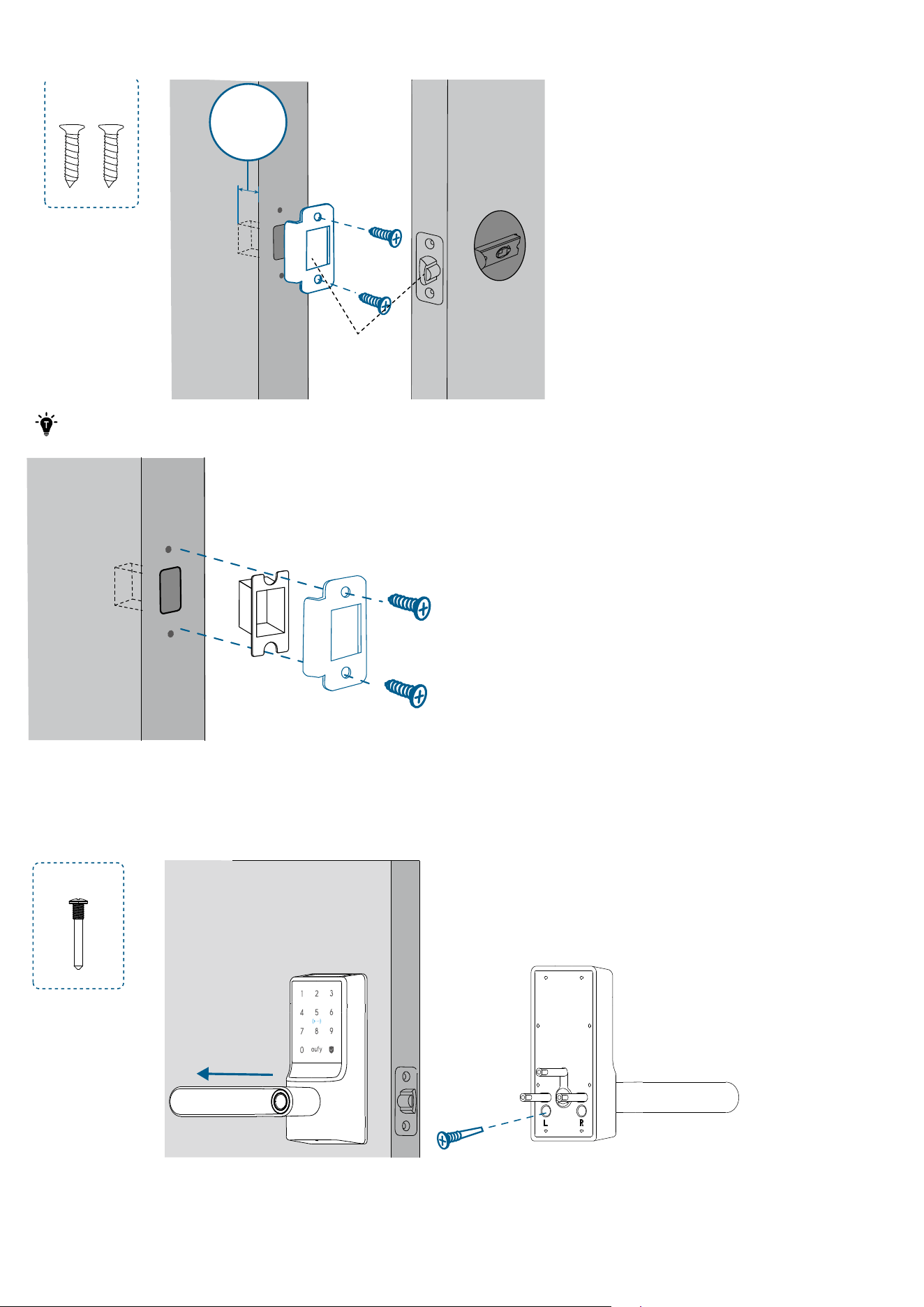
3.
Ensure the depth of the latch hole in the door frame is at least 1 in (25.4 mm), otherwise calibration may fail during setup,
and the lock may not function as expected.
D
Latch Hole
Depth
1 in (25.4mm)
· If the latch hole is too deep, you may install the provided plastic separator.
·The anti-picking mechanism works ONLY when the provided strike plate is installed.
Step 3. Install Exterior Assembly
1. Rotate the exterior assembly handle to the left or right. Then lock the screw into the corresponding screw hole.
Left Hand
:
G
Outside
Right Hand
:
G
Outside
2. If the spindle is not pre-installed into the exterior assembly, insert the spindle by aligning the spring head with the slot.
Make sure that the spindle is securely installed and cannot be pulled out. Then rotate the spindle to ensure it is
squarely straight to the ground.
F
3. Route the cable connected to the exterior assembly over the latch. Insert the spindle into the spindle hole of the latch.
Outside
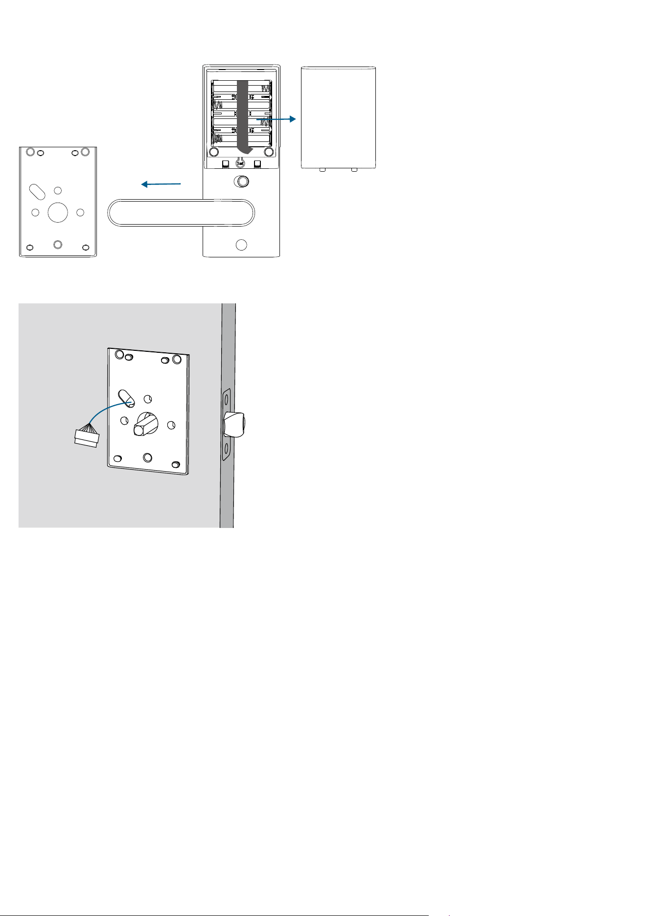
Step 4. Install Mounting Plate
1. Detach the mounting plate and battery cover from the interior assembly.
2. Position the mounting plate with the silicone pad against the door. Route the cable through the oval slot of the mounting
plate.
Inside
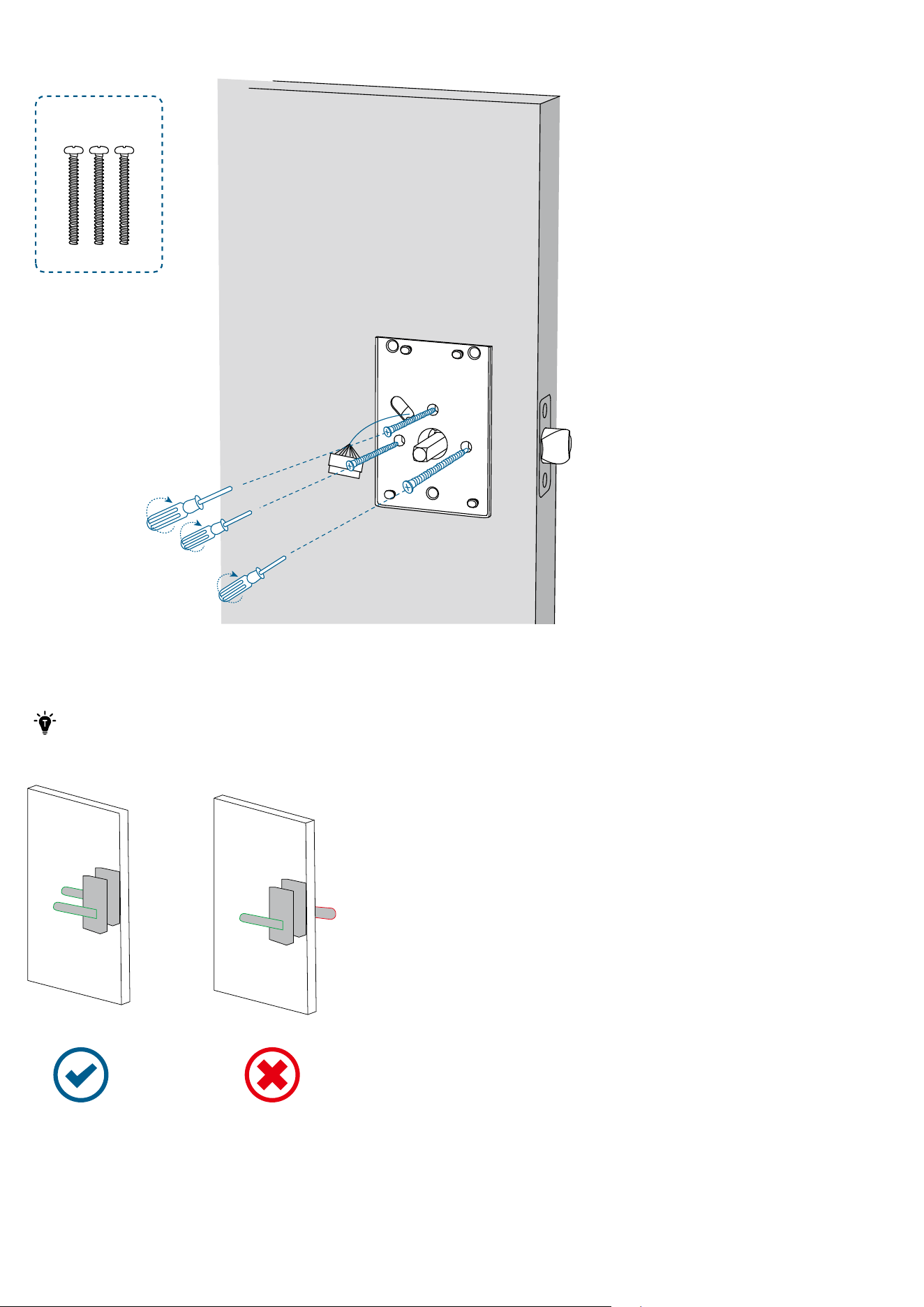
3. Align the mounting plate with the threaded screw receptacles of the exterior assembly. Tightly fasten the screws in place.
Set the screws with your hands, then use a screwdriver to secure them.
I
Inside
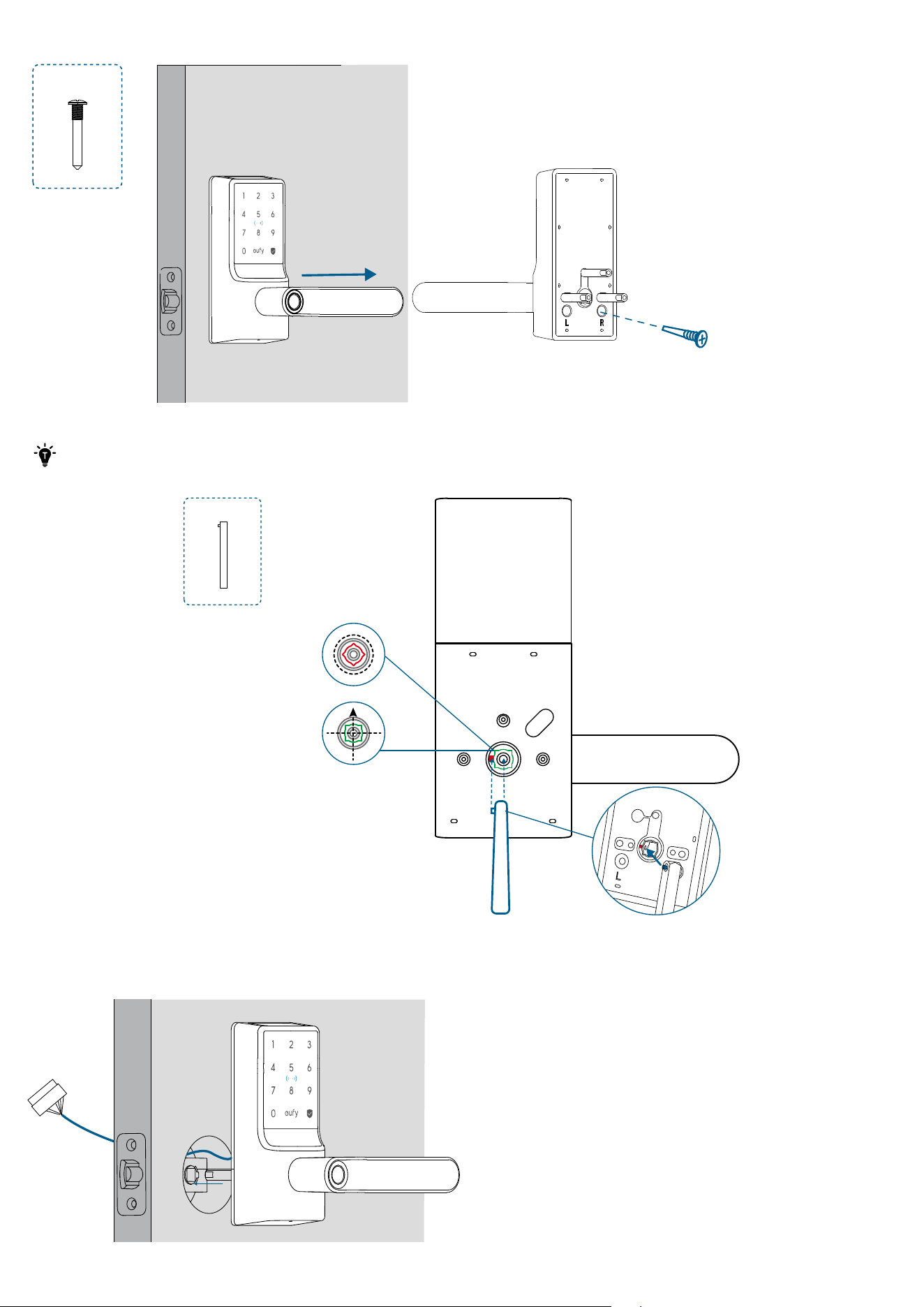
Step 5. Install Interior Assembly
1. Rotate the interior assembly handle to the left or right. Then lock the screw into the corresponding screw hole.
·
The handle must be horizontal when you tighten the screw.
·
Tighten the screw all the way down. Otherwise, the handle may get stuck.
·
Make sure that the interior handle direction is the same as the exterior one.
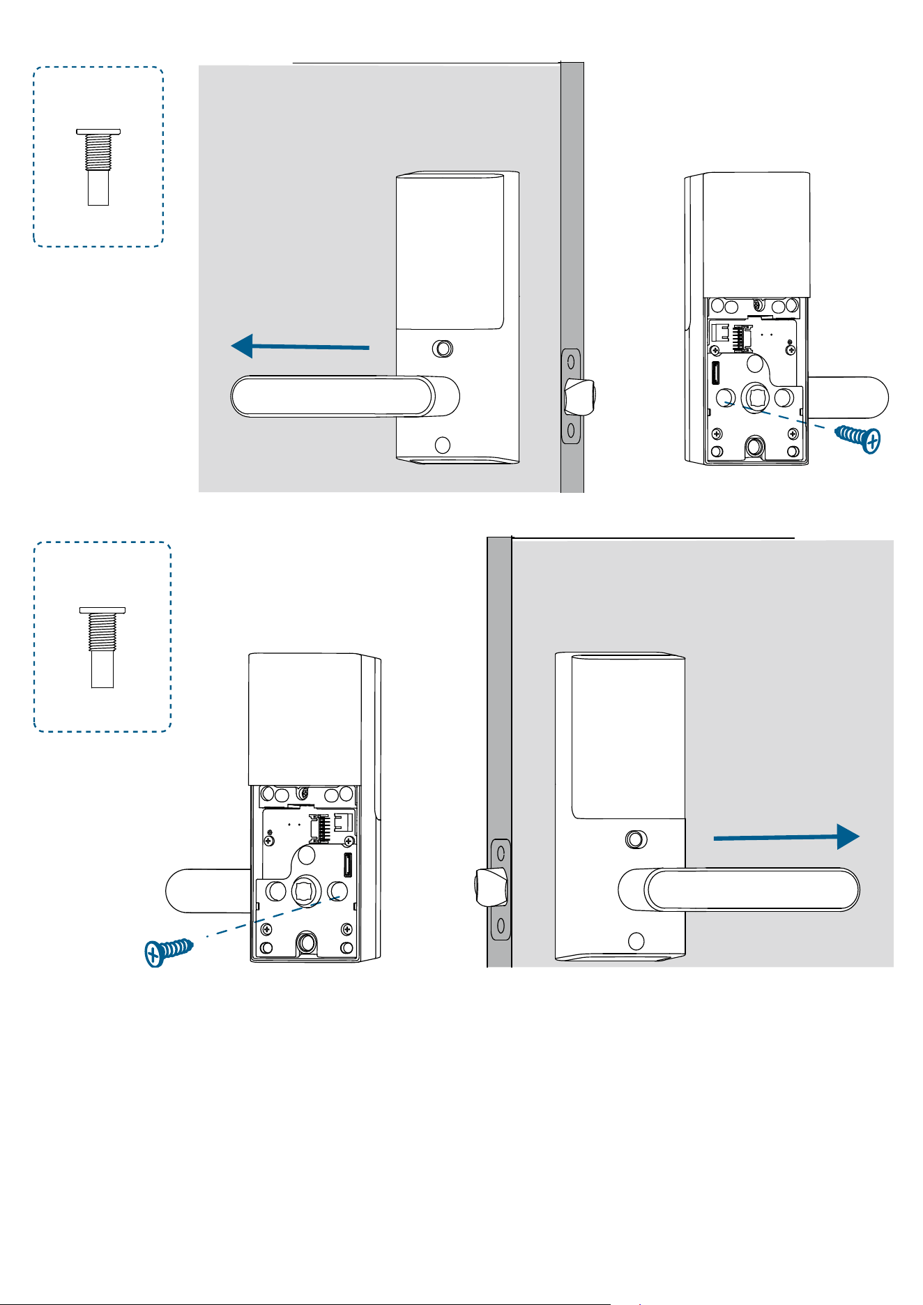
Left Hand
:
J
Inside
Right Hand
:
J
Inside
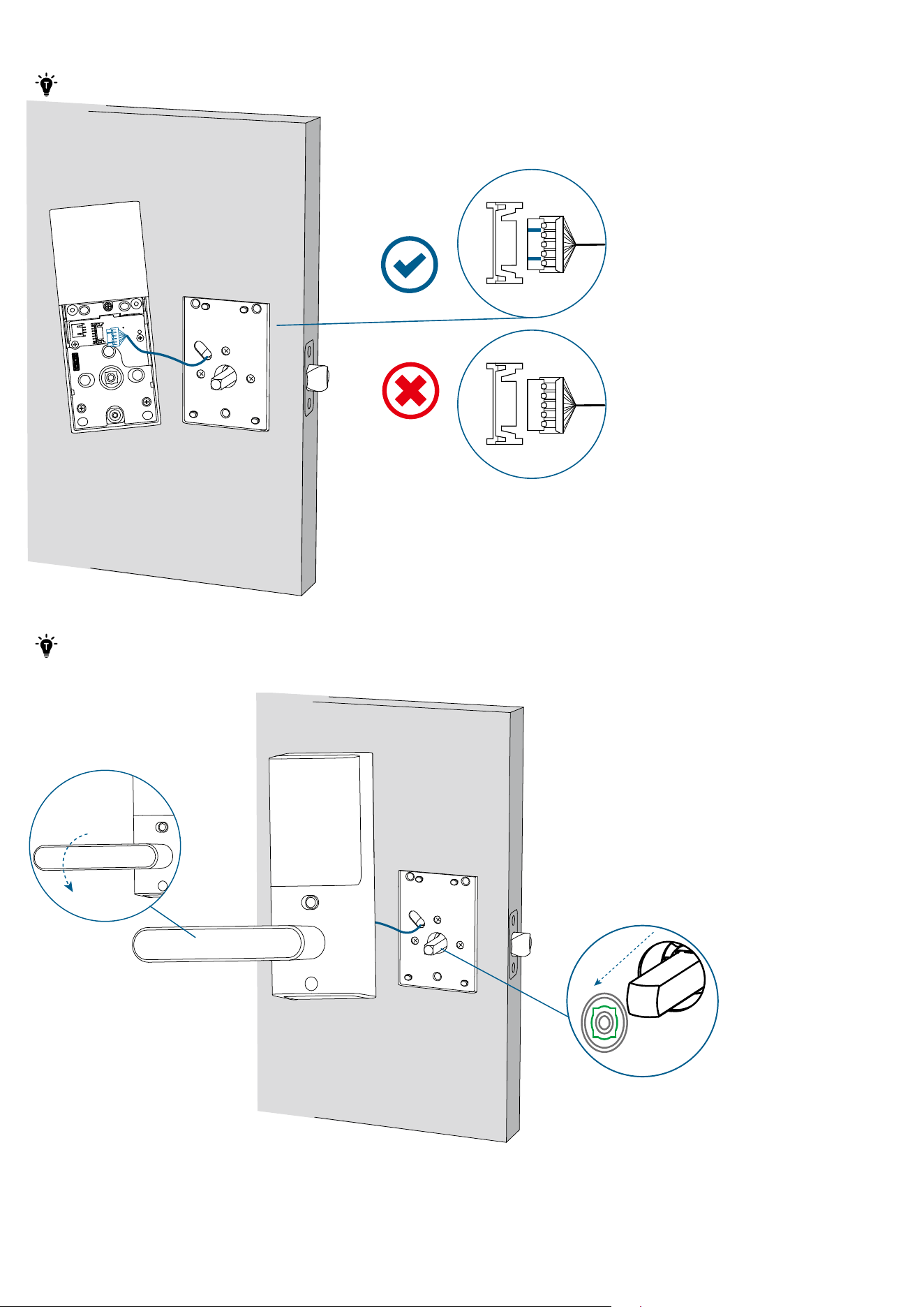
2. Plug the cable into the socket on the interior assembly. Route the cable around the spindle receiver to avoid pinching
during installation.
· Make sure the cable is tucked into the cavity on the back of the interior assembly.
Inside
3. Insert the spindle into the spindle receiver of the interior assembly.
·
Make sure the cable is tucked into the cavity on the back of the interior assembly.
·
After inserting the interior assembly, check if the latch moves properly by turning the handle.
Inside
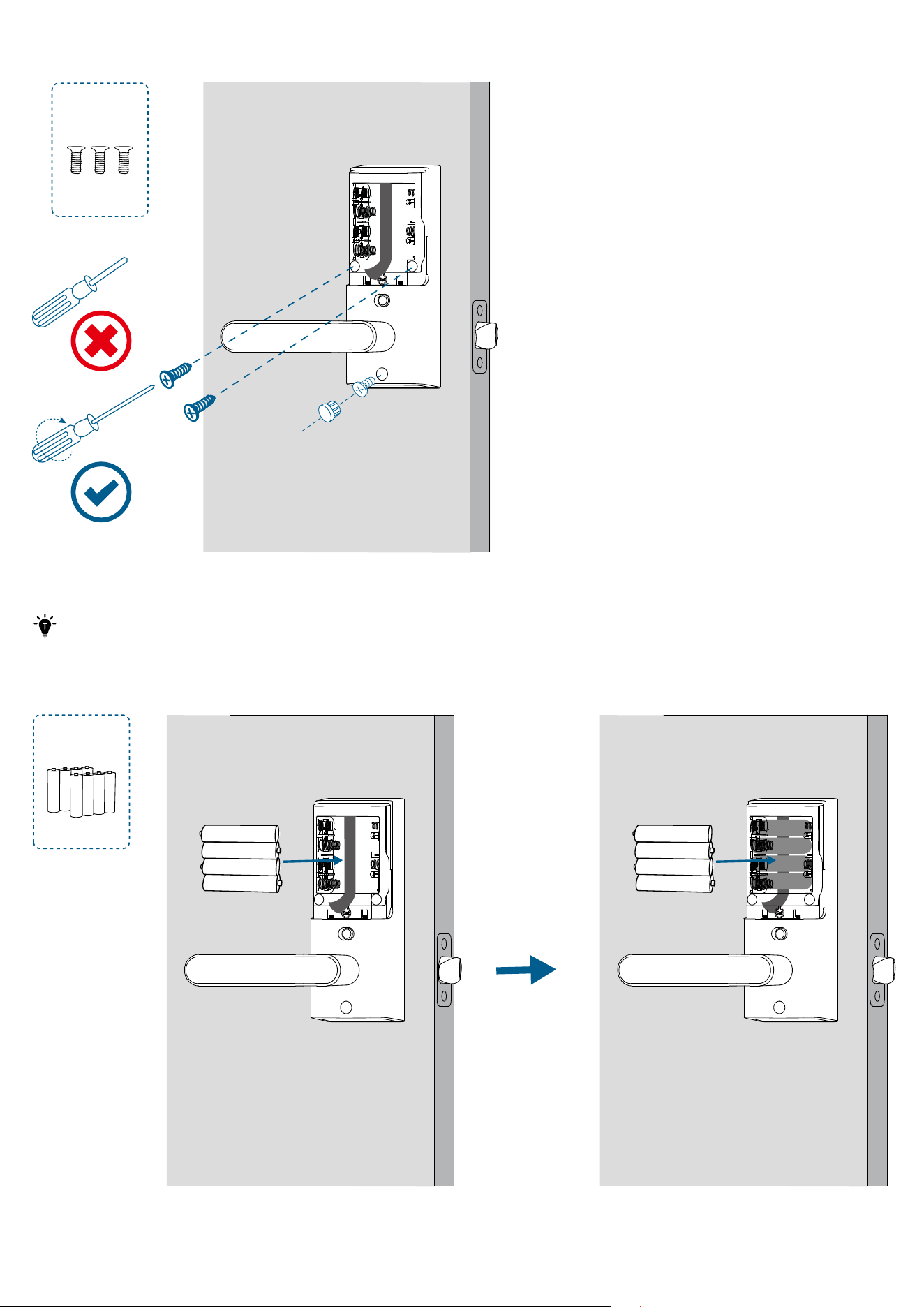
4. Fasten the interior assembly screws using a long screwdriver, and then insert the silicone plug into the hole below the
handle.
L
Inside
5. Install the 8 AA batteries provided with the correct polarity.
·
Do not put on the battery cover until the system setup is done in the app.
·
For your convenience, first install the bottom layer of 4 AA batteries.
·
When removing the batteries, first remove the upper layer and then gently pull the ribbon to lift the remaining
batteries out of the compartment.
M
Inside Inside
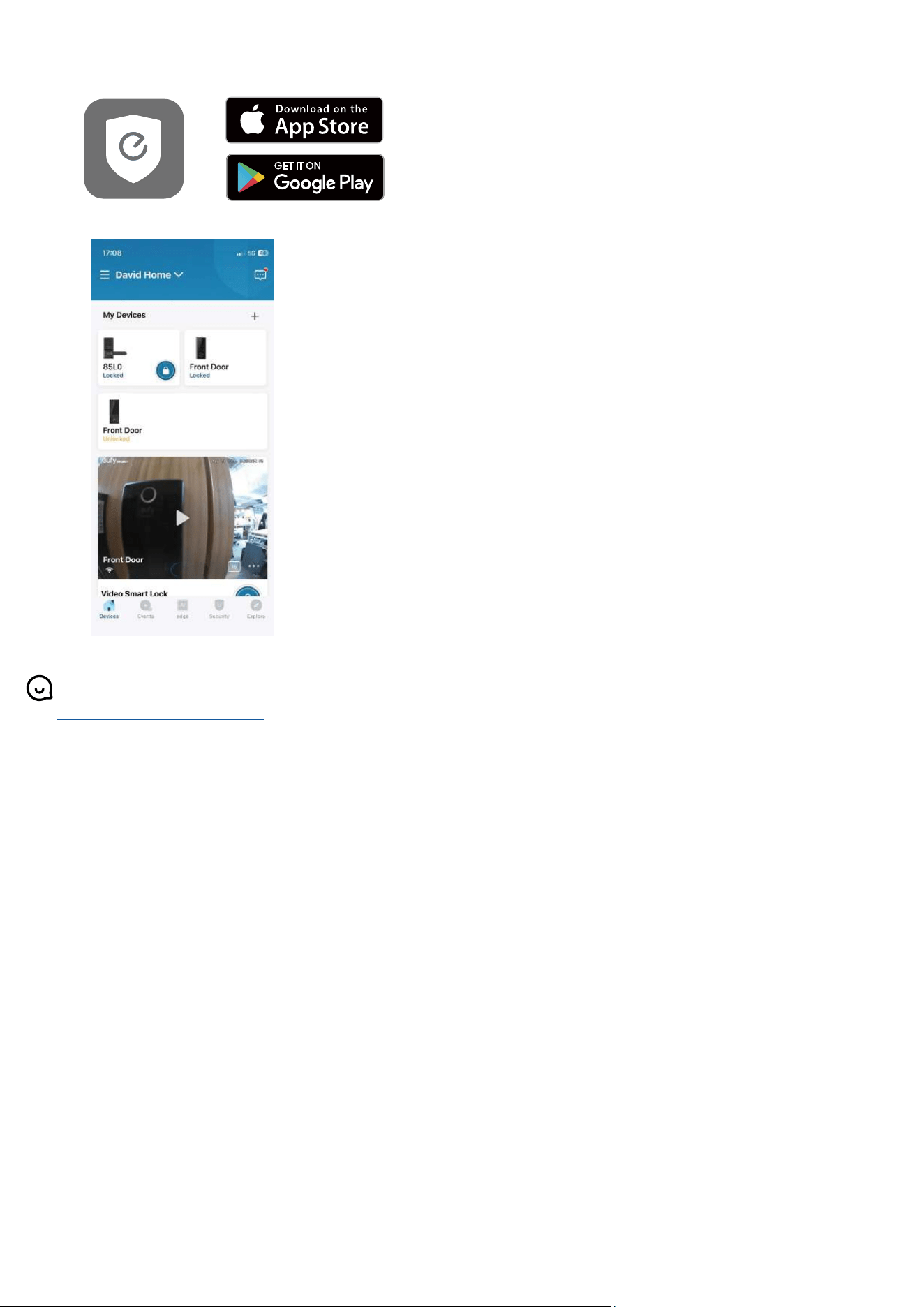
Setting Up the System
1. Download and install the eufy Security app, then sign up for an account.
2. Tap + to add the Smart Lever Lock to your device list.
3. Once setup is complete, install the battery cover. Your Smart Lever Lock is now ready to use.
For online support, tutorial videos, FAQs, and more information, please visit
https://support.eufy.com/s/.