INTEGRATED TALL DOUBLE DISHDRAWER™
PLANNING GUIDE
DD60DTX6I1 | DD60DTX6HI1

© FISHER & PAYKEL APPLIANCES LIMITED 2025 PAGE 290004476A PLANNING GUIDE DISH VERSION A - MAY 2025
DD60DTX6I1, DD60DTX6HI1
CONCEPT DESIGN PAGE
DEVELOPED AND DETAILED DESIGN PAGE DEVELOPED AND DETAILED DESIGN PAGE
SUPPORT
For additional design planning and installation support please
contact the Fisher & Paykel design support team.
designsupport@fisherpaykel.com
CONTENTS | DOUBLE DISHDRAWER™
CONTENTS
INTRODUCTION
This comprehensive planning guide provides you with the
framework and tools to achieve your desired design outcome
with Fisher & Paykel appliances. In this guide, you will find a
range of conceptual, detailed, and dimensional product
information to bring your ideas to life and create spaces that
truly reflect your vision.
NOTES
The models shown in this Planning Guide may not be available
in all markets and are subject to change at any time. Refer to
our website fisherpaykel.com for the latest document version.
Product specifications may vary from those shown.
This Planning Guide should not be used as installation guidance
for any product. Specific installation guidance will be available
with the product on delivery and on our website.
Specification guide 3
Specifications 4
Data sheets 5
Dishdrawer™ with pre-finished panels 6
Dishdrawer™ with custom panels 7
Accessories 8
Handles 9
Stainless steel panels 10
Planning considerations 11
Cavity specifications 12
Over width cavity specifications 13
Pre-finished toe kick 14
Custom toe kick specifications 15
Custom panel specifications 16
Custom door panel preparation 17
Custom panel preparation 18
Services 19
Service placement options 20
Service specifications 21
Electrical and plumbing specifications 22
Data sheets: Handles 23
Contemporary square fine handle 24
Contemporary round handle 25
Classic round handle 26
Professional round flush handle 27
Contents
<< CONTENTS

PAGE 3© FISHER & PAYKEL APPLIANCES LIMITED 2025PLANNING GUIDE DISH VERSION A - MAY 202590004476A
SPECIFICATION GUIDE
Specification guide
© FISHER & PAYKEL APPLIANCES LIMITED 2025 PAGE 490004476A PLANNING GUIDE DISH VERSION A - MAY 2025
The models shown in this Planning Guide may not be available in all markets and are subject to change at any time. Product specifications may vary from those shown. This Planning Guide should not be used as installation guidance for any product. Further information is required to safely and correctly
install the products featured here. Specific installation guidance will be available with the product on delivery and on our website fisherpaykel.com
DD60DTX6I1, DD60DTX6HI1
DD60DTX6I1, DD60DTX6HI1
SPECIFICATION GUIDE | INTEGRATED TALL DOUBLE DISHDRAWER™
Specifications
OVERVIEW
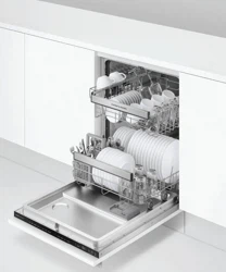
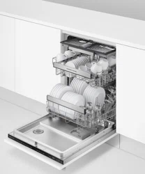
Install your DishDrawer™ Dishwasher into an existing kitchen
space or integrate into kitchen cabinetry. The touch-sensitive
control panel is located inside this Integrated model, leaving an
uninterrupted exterior that blends seamlessly with surrounding
cabinetry.
PRODUCTS
DD60DTX6I1
Integrated Dishdrawer™, 60cm wide
DD60DTX6HI1
Integrated Dishdrawer™ with water softener, 60cm wide
ACCESSORIES
PRE-FINISHED PANEL ADDD60DTPX
Brushed stainless steel pre-finished panels
PRE-FINISHED PANEL ADDD60DTPB
Black stainless steel pre-finished panels
HANDLES
Handles are available for the Dishdrawer™ including
Contemporary, Professional, and Classic styles. Options include
brushed aluminium, black, and stainless steel finishes. Two
handle kits are required for double drawer models.
FEATURES
1 Eight wash programs including Auto, 60min and Glassware,
while modifiers such as Sanitize, Dry+ and Quiet provide
added wash flexibility. The Quiet wash modifier reduces the
noise on some cycles while maintaining performance –
perfect for late night washing.
2 Tall top drawer fits full-size dinner plates up to 310mm, with
flexible racking for large cookware.
3 Wi-Fi capability and a SmartHQ™ app to see cycle status
and notifications.
4 Both drawers fit a true half load. Each drawer operates
independently, so you can wash one load while stacking the
other drawer, or wash simultaneously on separate cycles
5 For ease-of-use, these DishDrawer™ Dishwashers have a
knock to pause function. A knock on the front panel will
pause the dishwasher, which can be restarted by using the
start button.
<< CONTENTS

PAGE 5© FISHER & PAYKEL APPLIANCES LIMITED 2025PLANNING GUIDE DISH VERSION A - MAY 202590004476A
DATA SHEETS
Data sheets
IMPORTANT NOTE: Throughout this guide, dimensions may vary by ±2mm
(1/16''). Please read the Installation Guide for detailed information on
installing the product. For full installation instructions visit fisherpaykel.com
INDICATES PRODUCT DATUM -------------------------------------------
INDICATES CABINETRY CLEARANCES --------------------------------
© FISHER & PAYKEL LIMITED APPLIANCES 2025 PAGE 690004476A PLANNING GUIDE DISH - VERSION A - MAY 2025
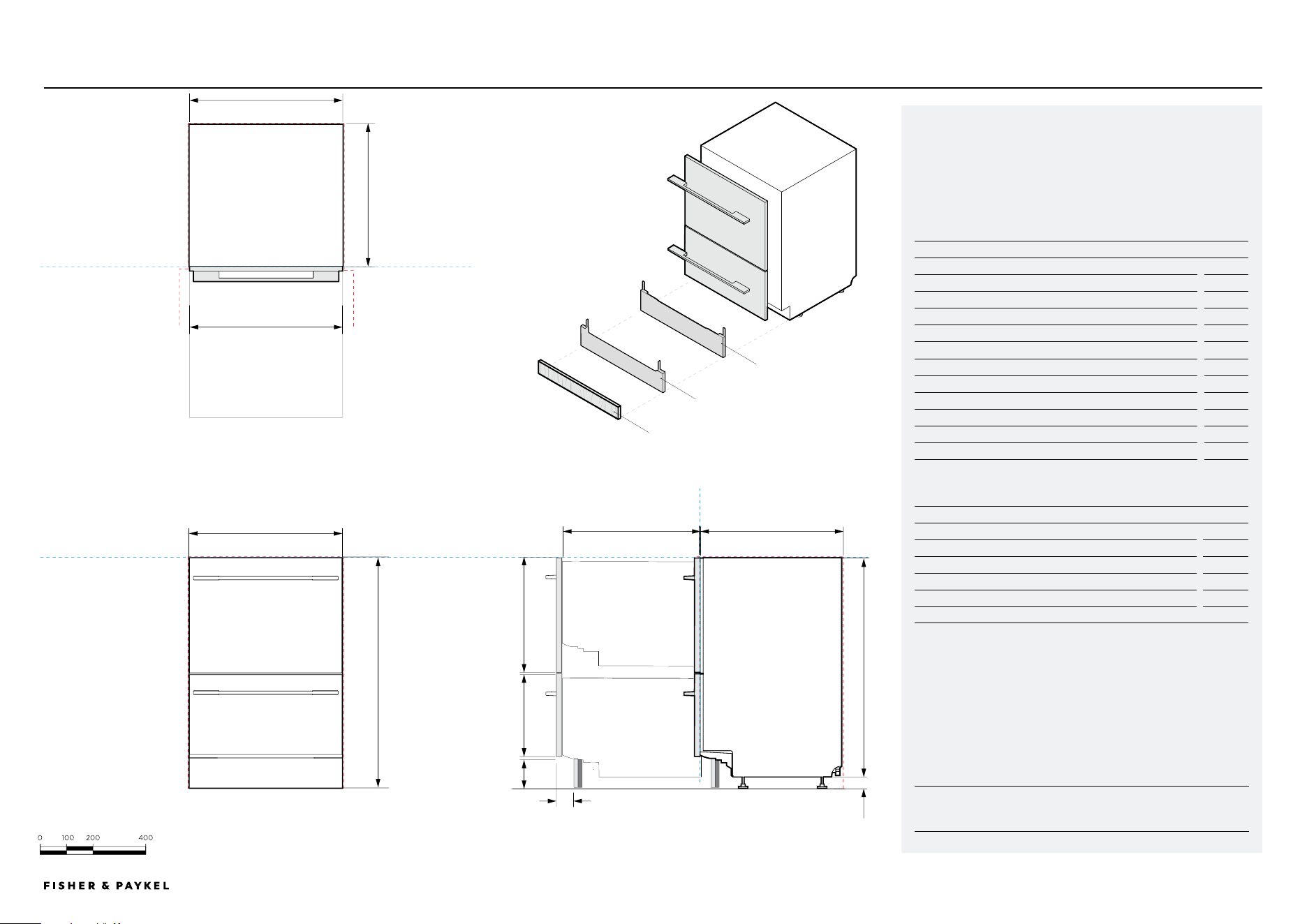
Model nos:
DD60DTX6I1 & DD60DTX6HI1
Shown with Stainless Steel Drawer Panels, ADDD60DTPX
Available Black Stainless Steel Panels, ADDD60DTPB
Shown with Contemporary Square Fine Handle, AHD5-OBDD-60
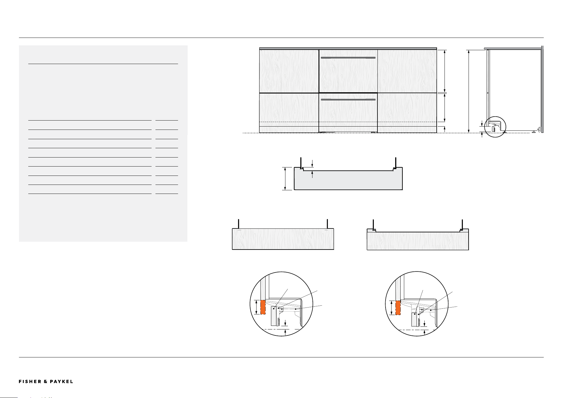
Product includes the following Toe Kick options:
Flush Pre-Finished Toe Kick
Recessed Pre-Finished Toe Kick (also used as a Custom toe kick bracket)
Product Dimensions
mm
A Overall height*
867 - 925
B Overall width of chassis
599
C Overall depth of chassis
553
D Height of chassis
854
E Height of feet*
10 - 70
F Height of upper drawer panel - minimum
442
G Height of lower drawer panel - minimum
311
H Height of toe kick
45 – 123
I Toe kick depth
40-120
J Maximum extension of drawer
527
K Ventilation gap between drawers
8
L Drawer panel width
596
*Depending on adjustment of leveling feet
Minimum Clearances
mm
Minimum inside height of cavity*
869
Minimum inside width of cavity
600
Minimum overall depth of cavity (includes panels)
578
Minimum clearance to corner cupboard
13
Minimum clearance to adjacent cupboard door
2
Minimum clearance between drawer panels
8
*Depending on adjustment of leveling feet
PROFILE VIEW
FRONT VIEW
864- 925mm
DATUM: TOP OF PRODUCT
DATUM: FRONT OF CHASSIS
FLOOR LEVEL
PLAN VIEW
DATUM: FRONT OF CHASSIS
Millimetres
Dishdrawer™ with pre-finished panels
A
B
C
D
E
F
G
H
J
K
L
DATA SHEETS | INTEGRATED DISHDRAWER™ WITH STAINLESS STEEL DRAWER PANELS
B
C
Flush pre-finished toe kick
(toe kick depth 40 - 56mm)
Recessed pre-finished toe kick
(toe kick depth 56 - 120mm)
DD60DTX6I1, DD60DTX6HI1
Custom toe kick
(toe kick depth 40 - 100mm)
I
CLEARANCE TO
CORNER CUPBOARD:
13MM
CLEARANCE TO
CORNER CUPBOARD:
13MM
<< CONTENTS
IMPORTANT NOTE: Throughout this guide, dimensions may vary by ±2mm
(1/16''). Please read the Installation Guide for detailed information on
installing the product. For full installation instructions visit fisherpaykel.com
INDICATES PRODUCT DATUM -------------------------------------------
INDICATES CABINETRY CLEARANCES --------------------------------
© FISHER & PAYKEL LIMITED APPLIANCES 2025 PAGE 790004476A PLANNING GUIDE DISH - VERSION A - MAY 2025
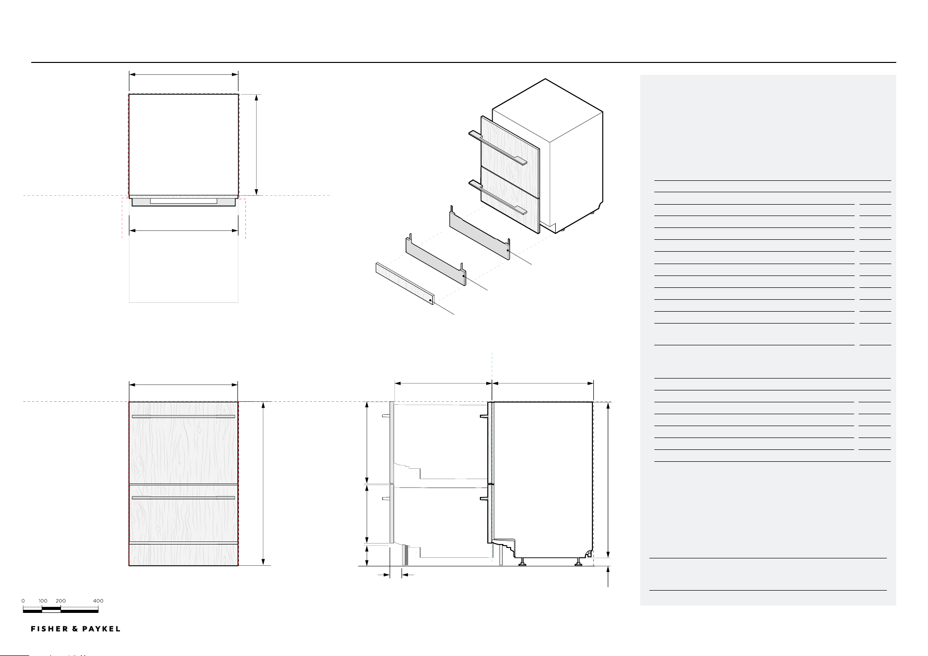
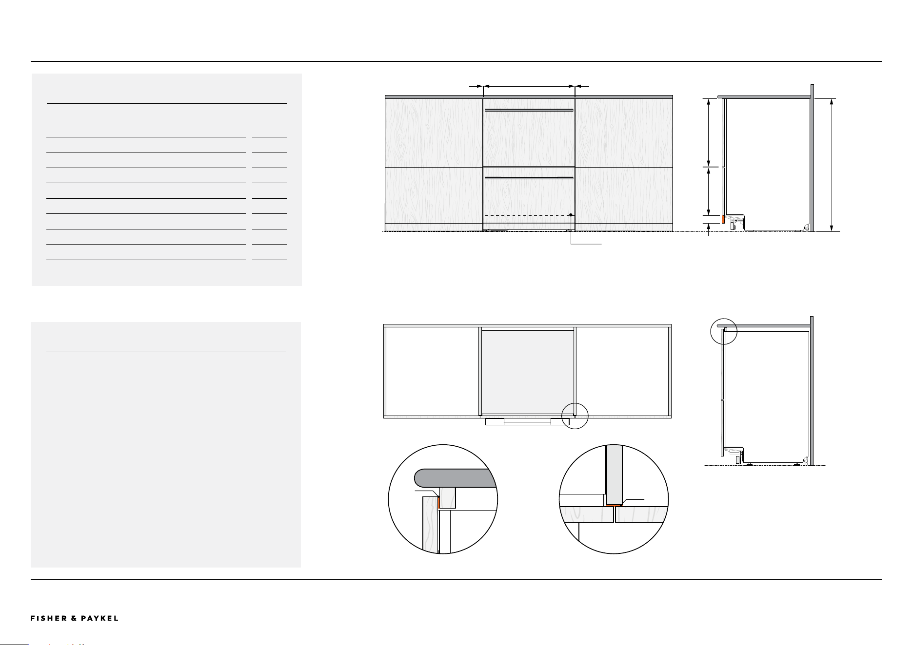
Model nos:
DD60DTX6I1 & DD60DTX6HI1
Shown with Custom Drawer Panels
Shown with Contemporary Square Fine Handle, AHD5-OBDD-60S
Product includes the following Toe Kick options:
Flush Pre-Finished Toe Kick
Recessed Pre-Finished Toe Kick (also used as a Custom toe kick bracket)
Product Dimensions
mm
A Overall height*
867 - 925
B Overall width of chassis
599
C Overall depth of chassis
553
D Height of chassis
854
E Height of feet*
10 - 70
F Height of upper drawer panel - minimum
442
G Height of lower drawer panel - minimum
311
H Height of toe kick
45 – 123
I Toe kick depth
40-120
J Maximum extension of drawer
527
K Ventilation gap between drawers
8
L Drawer panel width (custom panels widths can vary to fit
adjacent cabinet doors/drawers)
596
*Depending on adjustment of leveling feet
Minimum Clearances
mm
Minimum inside height of cavity*
869
Minimum inside width of cavity
600
Minimum overall depth of cavity**
578
Minimum clearance to corner cupboard
13
Minimum clearance to adjacent cupboard door
2
Minimum clearance between drawer panels
8
*Depending on adjustment of leveling feet
**Assumes 19mm drawer panels on adjacent cabinetry
NOTE: Custom drawer panel and toe kicks to be manufactured/fitted by
cabinetmaker.
PROFILE VIEW
FRONT VIEW
864 - 925mm
DATUM: TOP OF PRODUCT
DATUM: FRONT OF CHASSIS
FLOOR LEVEL
PLAN VIEW
DATUM: FRONT OF CHASSIS
Millimeters
Dishdrawer™ with custom panels
A
B
C
D
E
F
G
H
J
K
L
DD60DTX6I1, DD60DTX6HI1
DATA SHEETS | INTEGRATED DISHDRAWER™ WITH CUSTOM DRAWER PANELS
C
I
Flush pre-finished toe kick
(toe kick depth 40 - 56mm)
Recessed pre-finished toe kick
(toe kick depth 56 - 120mm)
B
CLEARANCE TO
CORNER CUPBOARD:
13MM
CLEARANCE TO
CORNER CUPBOARD:
13MM
Custom toe kick
(toe kick depth 40 - 100mm)
<< CONTENTS

© FISHER & PAYKEL LIMITED APPLIANCES 2025 PAGE 890004476A PLANNING GUIDE DISH - VERSION A - MAY 2025
ACCESSORIES
Accessories
The models shown in this Planning Guide may not be available in all markets and are subject to change at any time. Product specifications may vary from those shown. This Planning Guide should not be used as installation guidance for any
product. Further information is required to safely and correctly install the products featured here. Specific installation guidance will be available on our website fisherpaykel.com
© FISHER & PAYKEL LIMITED APPLIANCES 2025 PAGE 990004476A PLANNING GUIDE DISH - VERSION A - MAY 2025
ACCESSORIES | HANDLES
A
D
E
C
B
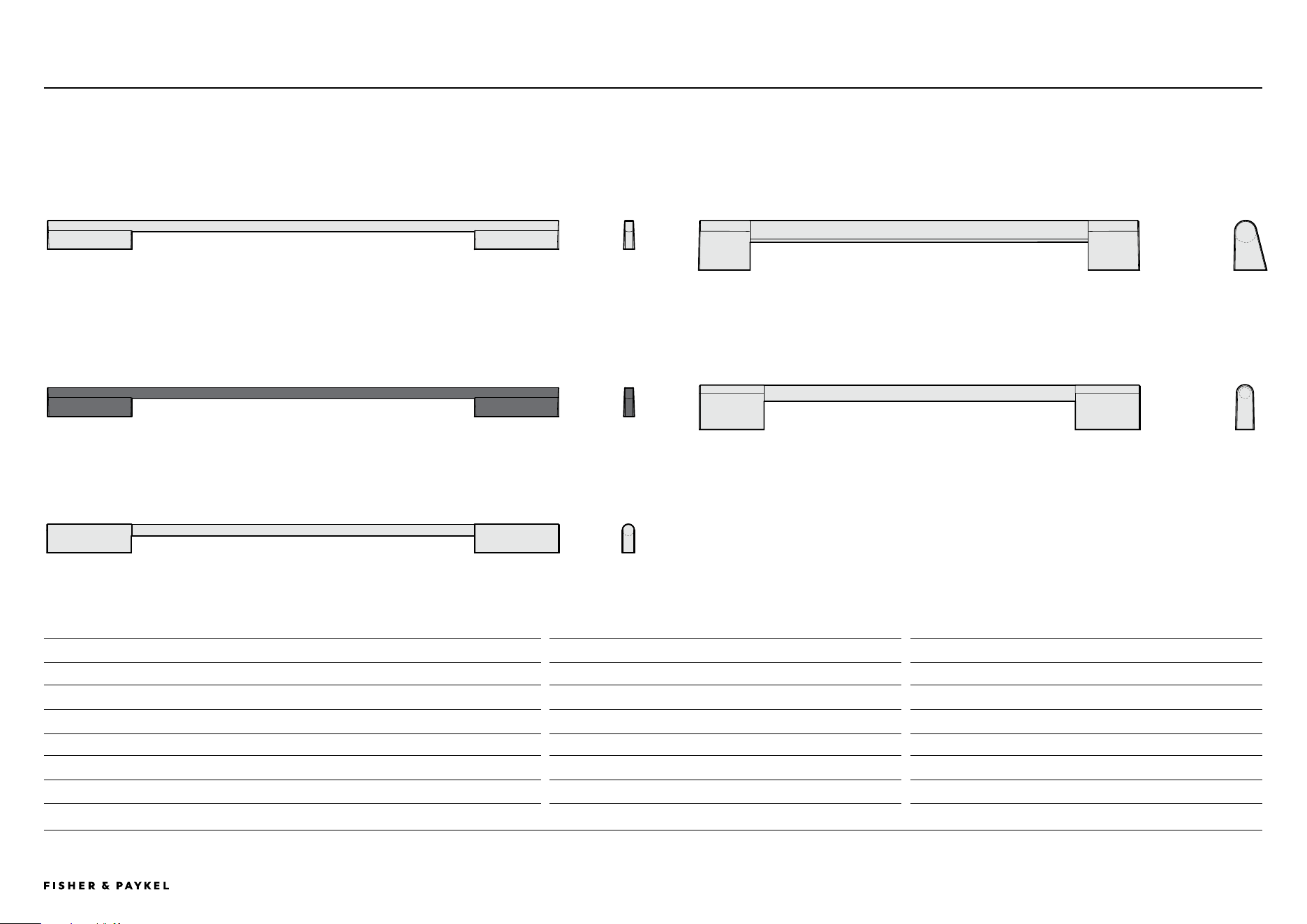
Handles
Handle kits
Style Model Finish
A Contemporary square fine AHD5-OBDD-60SX
Brushed aluminium
B Contemporary square fine black AHD5-OBDD-60SB
Brushed black aluminium
C Contemporary round AHS-OBDD-60S Stainless steel
D Professional round flush AHP3-DWDD-60S
Stainless steel
E Classic round AHCL-DDDW-60X
Stainless steel
Note: Double Dishwasher requires two handle kits.
<< CONTENTS
The models shown in this Planning Guide may not be available in all markets and are subject to change at any time. Product specifications may vary from those shown. This Planning Guide should not be used as installation guidance for any
product. Further information is required to safely and correctly install the products featured here. Specific installation guidance will be available on our website fisherpaykel.com
© FISHER & PAYKEL LIMITED APPLIANCES 2025 PAGE 1090004476A PLANNING GUIDE DISH - VERSION A - MAY 2025
ACCESSORIES | STAINLESS STEEL PANELS
A
B
D
E
C
A
B
D
E
C
PRE-FINISHED PANEL ADDD60DTPX
BRUSHED STAINLESS STEEL
PRE-FINISHED PANEL ADDD60DTPB
BLACK STAINLESS STEEL
PRE-FINISHED PANELS
Brushed Stainless Steel - ADDD60DTPX
Black Stainless Steel - ADDD60DTPB
Panel Dimensions mm
A Width of panels 596
B Height of top drawer panel 442
C Height of bottom drawer panel 311
D Handle fixing point from top of panel 72
E Handle fixing point from side of panel 81.5
Panel depth 18
Note: Custom toe kick panels can installed alongside pre-finished
panels using the recessed pre-finished toe kick as a mounting jig.
Stainless steel panels
<< CONTENTS

PAGE 11© FISHER & PAYKEL APPLIANCES LIMITED 2025PLANNING GUIDE DISH VERSION A - MAY 202590004476A
PLANNING CONSIDERATIONS
Planning considerations
© FISHER & PAYKEL APPLIANCES LIMITED 2025 PAGE 1290004476A PLANNING GUIDE DISH VERSION A - MAY 2025
The models shown in this Planning Guide may not be available in all markets and are subject to change at any time. Product specifications may vary from those shown. This Planning Guide should not be used as installation guidance for any product. Further information is required to safely and correctly
install the products featured here. Specific installation guidance will be available with the product on delivery and on our website fisherpaykel.com
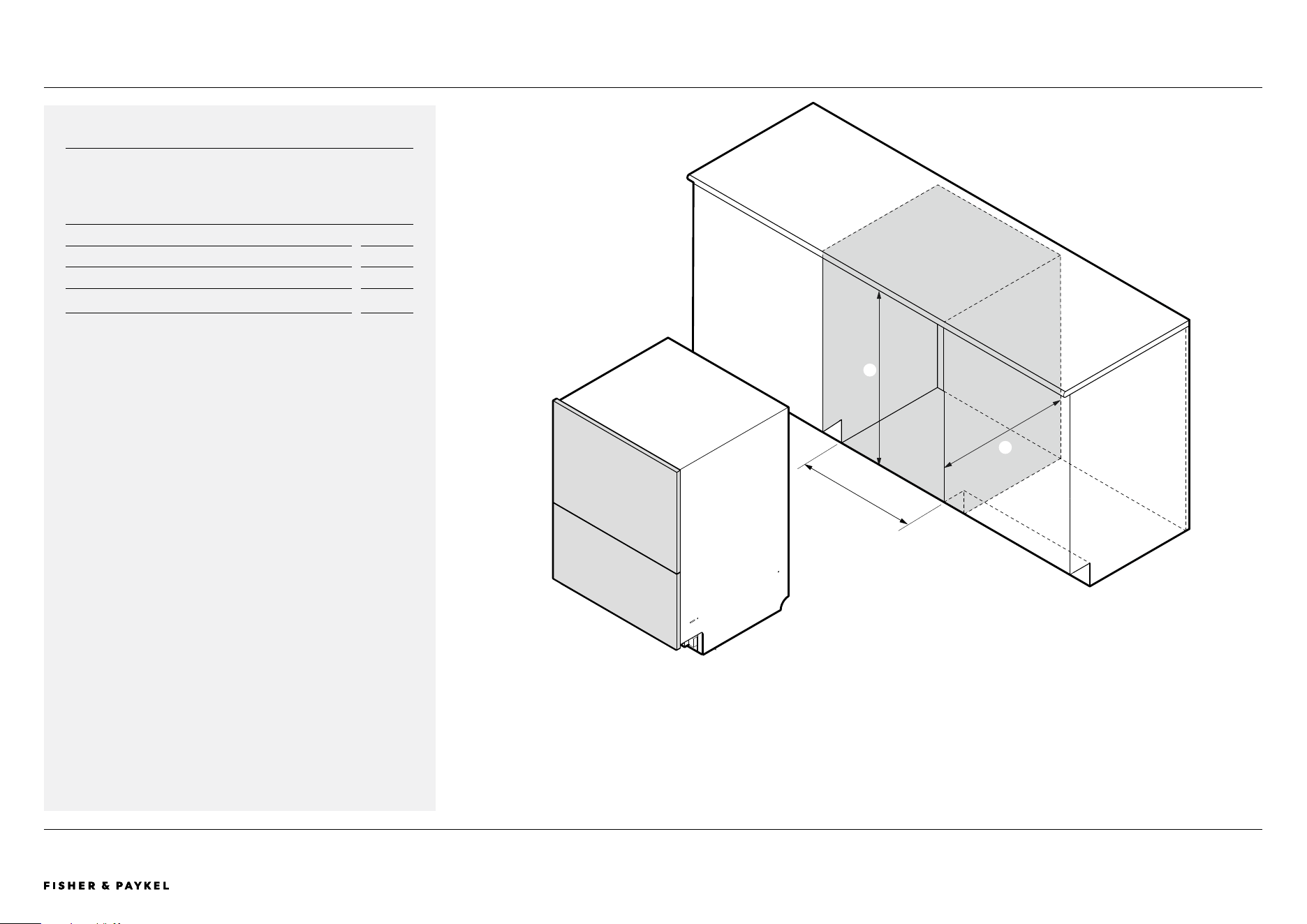
PLANNING CONSIDERATIONS | CAVITY SPECIFICATIONS
B
Cavity specifications
Cavity Dimensions mm
A Cavity height* 869-927
B Minimum cavity width 600
C Minimum cavity depth** 578
*Cavity height depends on adjustment of levelling feet.
**Ensure there are no obstructions in the cavity if minimum cavity
depth, width or height are specified.
CAVITY SPECIFICATIONS
The cavity height will vary according to your cabinetry design
and counter top height.
A
C
<< CONTENTS
© FISHER & PAYKEL APPLIANCES LIMITED 2025 PAGE 1390004476A PLANNING GUIDE DISH VERSION A - MAY 2025
The models shown in this Planning Guide may not be available in all markets and are subject to change at any time. Product specifications may vary from those shown. This Planning Guide should not be used as installation guidance for any product. Further information is required to safely and correctly
install the products featured here. Specific installation guidance will be available with the product on delivery and on our website fisherpaykel.com
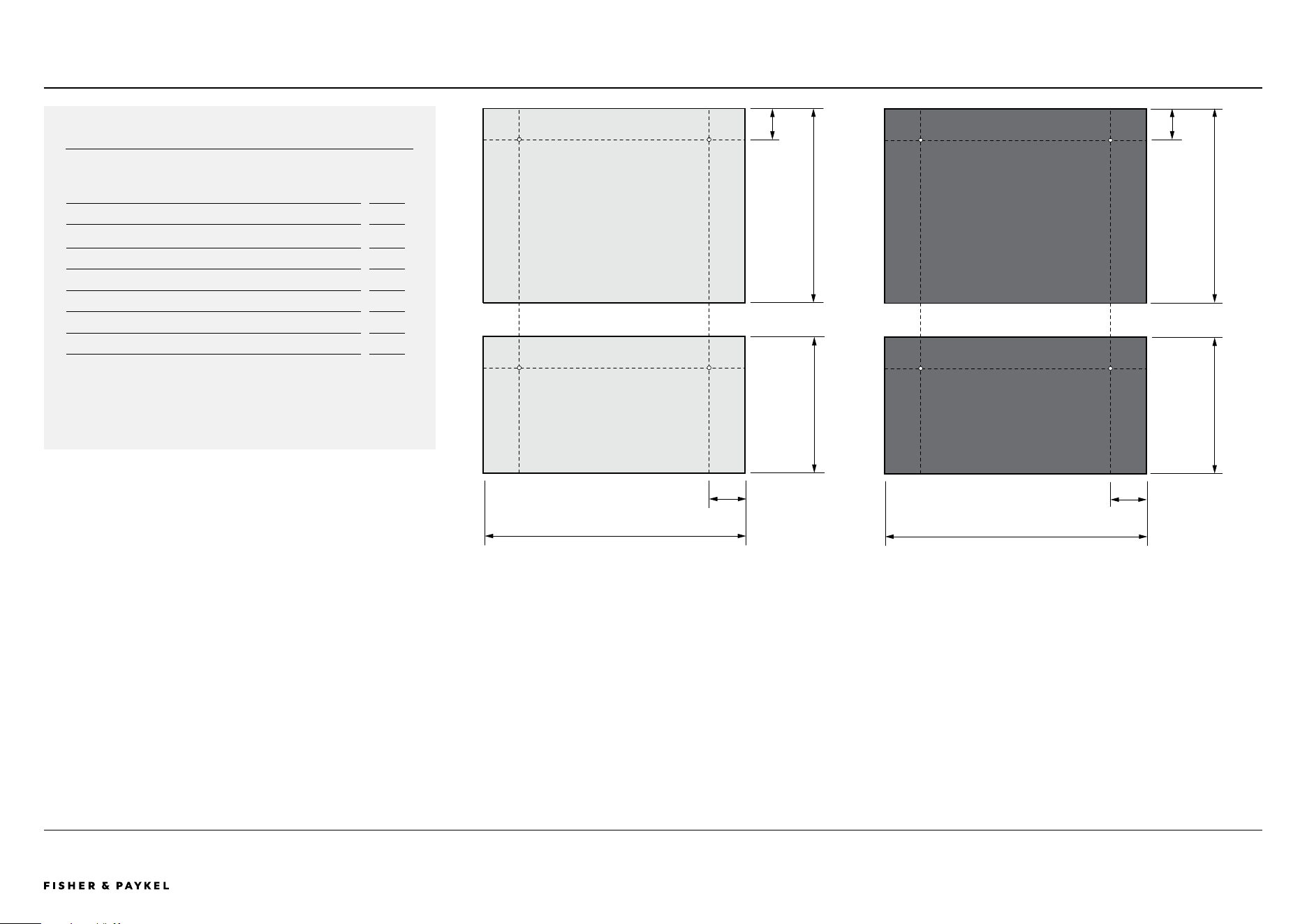
PACKING PLACEMENT FOR OVER SIZED CAVITY WIDTHS PLANNING CONSIDERATIONS | CAVITY SPECIFICATIONS
Dimensions mm
A Width between packers 600
B Center of fixing points from top of chassis 640
CAVITY PACKING PLACEMENT
The dishwasher must be secured through chassis and into the
cabinet sides. If the cavity is over width, packers must be
installed to avoid bowing the chassis.
Extra packers are recommended above the fixing points.
Side and top brackets may be installed and fixed to the edge of
the cabinet.
A
Over width cavity specifications
B
<< CONTENTS
The models shown in this Planning Guide may not be available in all markets and are subject to change at any time. Product specifications may vary from those shown. This Planning Guide should not be used as installation guidance for any
product. Further information is required to safely and correctly install the products featured here. Specific installation guidance will be available on our website fisherpaykel.com
© FISHER & PAYKEL LIMITED APPLIANCES 2025 PAGE 1490004476A PLANNING GUIDE DISH - VERSION A - MAY 2025
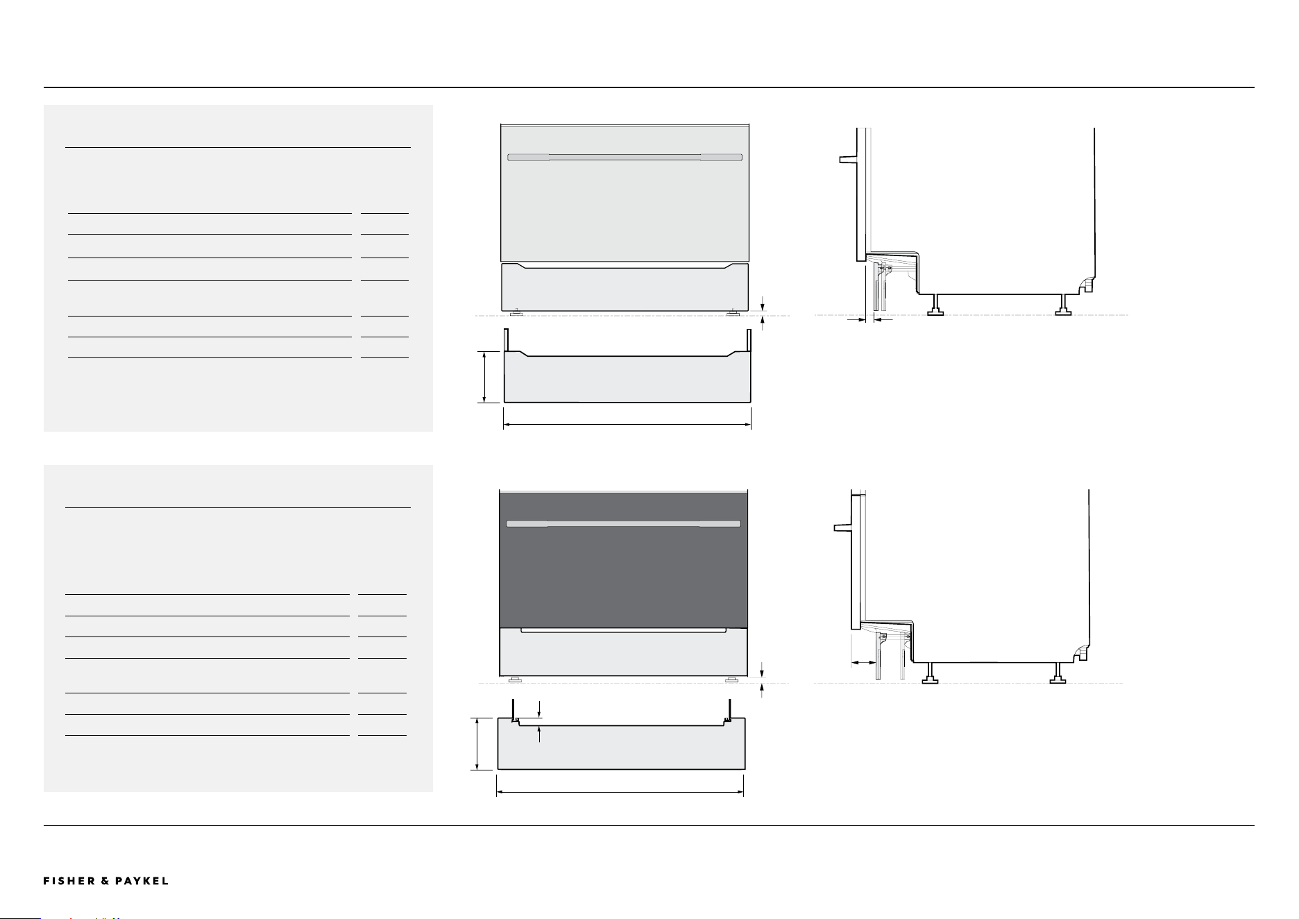
RECESSED PRE-FINISHED TOE KICK
Suitable for a toe kick depth of 56 to 120mm. The pre-finished
toe kick height can be cut to fit as needed.
The recessed toe kick is also used as a mount for custom panels.
FLUSH PRE-FINISHED TOE KICK
Suitable for a toe kick depth of 40 to 56mm. The pre-finished
toe kick height can be cut to fit as needed.
ACCESSORIES | PRE - FINISHED TOE KICK
A
C
D
E
F
H
Dimensions mm
A Toe kick height 45 - 123
B Toe kick width 595
C Minimum clearance between toe kick panel and
floor
12
D Depth of toe kick recess* 40 - 56
*Back of drawer to front of toe kick
RECESSED PRE-FINISHED TOE KICK
FLUSH PRE-FINISHED TOE KICK
B
G
Pre-finished toe kick
Dimensions mm
E Toe kick height 45 - 123
F Toe kick width 595
G Minimum clearance between toe kick panel and
floor
12
H Depth of toe kick recess* 56 - 120
*Back of drawer to front of toe kick
<< CONTENTS
© FISHER & PAYKEL APPLIANCES LIMITED 2025 PAGE 1590004476A PLANNING GUIDE DISH VERSION A - MAY 2025
The models shown in this Planning Guide may not be available in all markets and are subject to change at any time. Product specifications may vary from those shown. This Planning Guide should not be used as installation guidance for any product. Further information is required to safely and correctly
install the products featured here. Specific installation guidance will be available with the product on delivery and on our website fisherpaykel.com
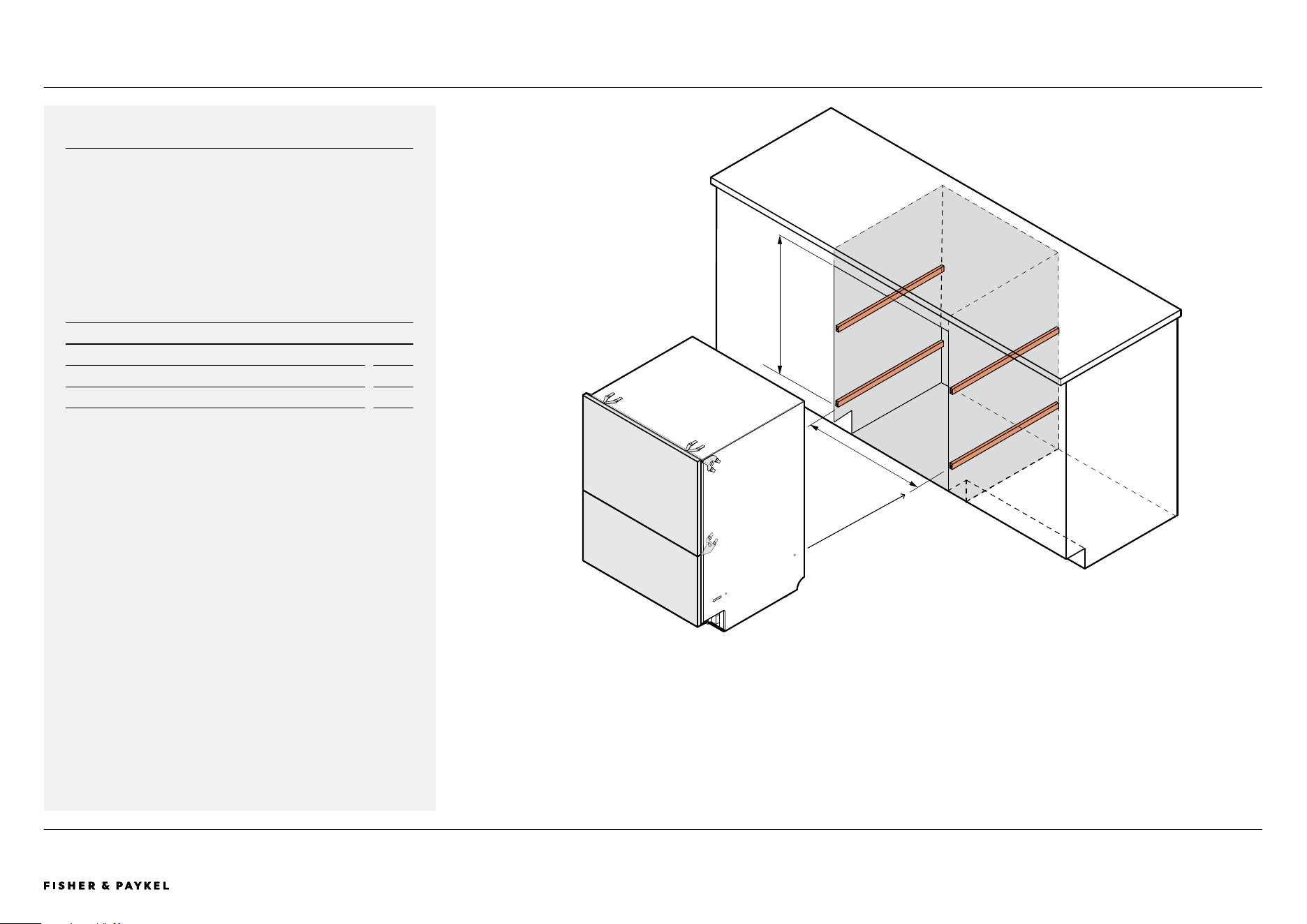
PLANNING CONSIDERATIONS | CUSTOM TOE KICK SPECIFICATIONS
A
B
D
A
F
D
1
CUSTOM TOE KICK SPECIFICATIONS
The custom panel is fixed to the recessed pre-finished panel.
The finished toe kick height will vary according to the toe kick
depth and the adjusted height of the dishwasher.
The bottom drawer panel can be extended over the toe kick up
to a maximum of 50mm.
Toe kick Dimensions mm
A Product height 867 - 925
B Top panel height minimum 442
C Bottom panel height minimum 311
D Bottom panel maximum extension 50
E Minimum toe kick clearance to floor 12
F Toe kick panel height* 45 – 123
G Toe kick depth 40 - 120
*For overall cabinet toe kick height include the 12mm clearance
gap.
Custom drawer panel and toe kicks should be manufactured and
fitted by a cabinetmaker.
SECTION DETAIL VIEW 1
TOE KICK DEPTHS 56 - 120MM
FRONT VIEW SECTION VIEW
CUSTOM TOE KICK PANEL ALIGNMENT FOR
40MM TO 56MM DEPTH
RECESSED PRE-FINISHED TOE KICK 40 - 100MM DEPTH
123mm
19mm
CUSTOM TOE KICK PANEL ALIGNMENT FOR
56MM TO 120M DEPTH
Custom toe kick specifications
B
C
D
SECTION DETAIL VIEW 1
TOE KICK DEPTHS 40 - 56MM
D
E
E
Recessed
pre-finished
toe kick
Toe kick
sliding rail
Custom
toe kick
Recessed
pre-finished
toe kick
Toe kick
sliding rail
Custom
toe kick
<< CONTENTS
The models shown in this Planning Guide may not be available in all markets and are subject to change at any time. Product specifications may vary from those shown. This Planning Guide should not be used as installation guidance for any
product. Further information is required to safely and correctly install the products featured here. Specific installation guidance will be available on our website fisherpaykel.com
© FISHER & PAYKEL LIMITED APPLIANCES 2025 PAGE 1690004476A PLANNING GUIDE DISH - VERSION A - MAY 2025
PLANNING CONSIDERATIONS | CUSTOM PANEL SPECIFICATIONS
BD
C
E
F
CUSTOM PANEL SPECIFICATIONS
Ensure that there are no obstructions under the counter top if
the dishwasher is installed directly below.
Dimensions mm
A Height of cavity 869-927
B Minimum panel width 596
C Minimum top panel height 442
D Minimum clearance gap between drawers 2
E Minimum bottom panel height 311
F Maximum bottom panel extension 50
G Minimum ventilation gap 8
A
SECTION VIEW
Custom panel specifications
D
Minimum panel height
EXTENDING CUSTOM PANELS
Custom panels may need to extend to cover cabinet side walls
or frames, or to create recessed handles.
Make sure the dishwasher drawer can always close securely
against the seals on the chassis.
The dishwasher drawers must seal properly when closed to
prevent humidity escape and condensation, which can damage
the custom panel.
If the custom drawer panel contacts any cabinetry, the seal may
be compromised, allowing humidity to escape and damage the
drawer panels or cabinetry.
SECTION VIEW
Gap
3
PLAN VIEW
DETAIL 2
DETAIL 3
Gap
2
FRONT VIEW
MINIMUM CAVITY HEIGHT WITH EXTENDED PANEL
G
<< CONTENTS

PAGE 17© FISHER & PAYKEL APPLIANCES LIMITED 2025PLANNING GUIDE DISH VERSION A - MAY 202590004476A
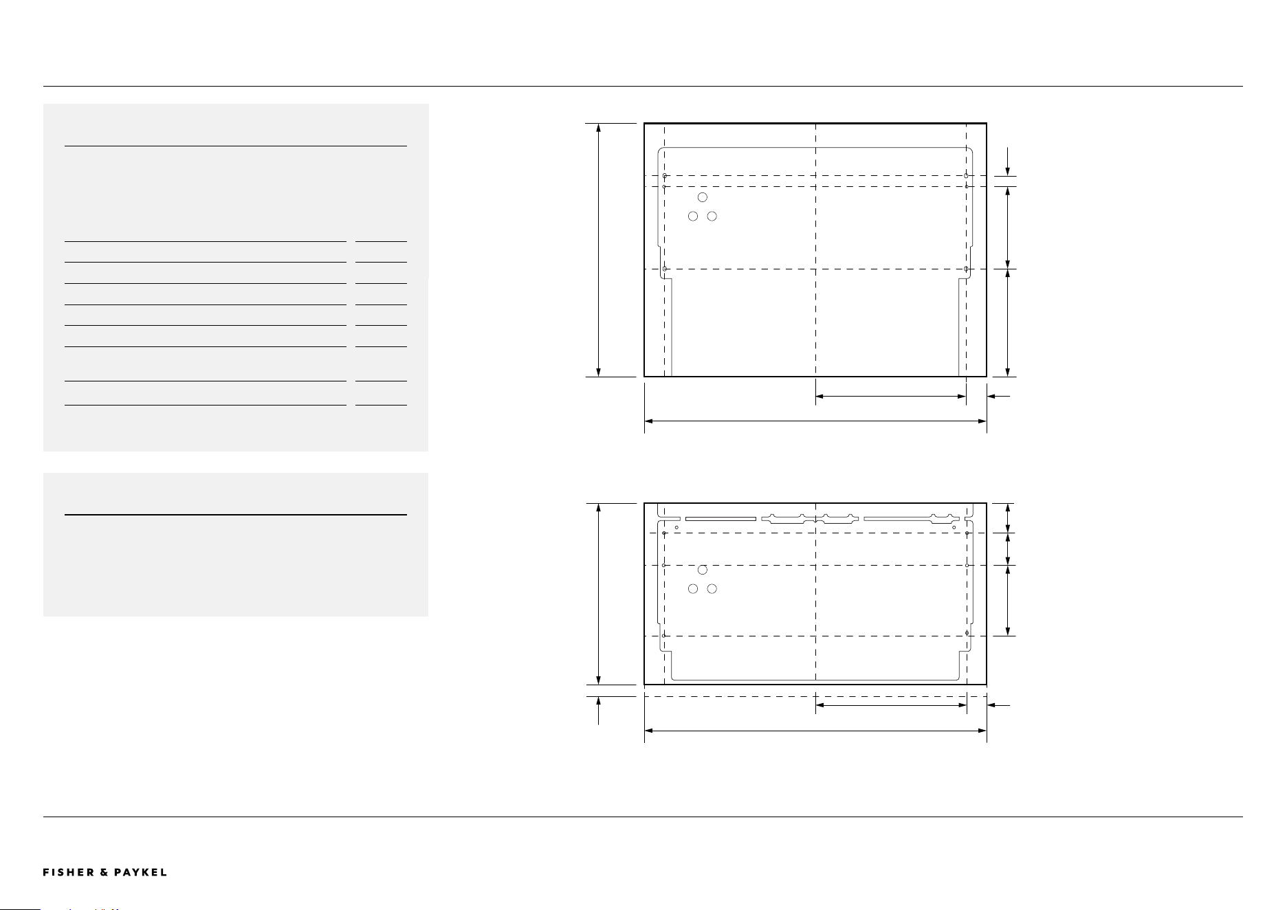
CUSTOM DRAWER PANEL PREPARATION
Custom door panel preparation
© FISHER & PAYKEL APPLIANCES LIMITED 2025 PAGE 1890004476A PLANNING GUIDE DISH VERSION A - MAY 2025
The models shown in this Planning Guide may not be available in all markets and are subject to change at any time. Product specifications may vary from those shown. This Planning Guide should not be used as installation guidance for any product. Further information is required to safely and correctly
install the products featured here. Specific installation guidance will be available with the product on delivery and on our website fisherpaykel.com
PLANNING CONSIDERATIONS | CUSTOM PANEL DETAILS
CUSTOM PANEL SPECIFICATIONS
Panel width and height will vary according to your cabinet
specifications.
Custom drawer panel and toe kicks should be manufactured and
fitted by a cabinetmaker.
Panel Dimensions mm
A Minimum panel width 596
B Top drawer panel minimum height 442
C Bottom drawer panel minimum height 311
D Maximum bottom drawer panel extension 50
Maximum panel weight per drawer panel including
handle
9kg
Custom panel preparation
A
B
C
A
264mm
188mm
143mm
19mm
264mm
52mm
56mm
122mm
TOP PANEL - BACK VIEW
BOTTOM PANEL - BACK VIEW
D
34mm
34mm
TOP PANEL EXTENSION
The top panel can be extended upwards. This can aect the ease
of using the internal control panel.
For additional support please contact the Fisher & Paykel design
support team at designsupport@fisherpaykel.com
<< CONTENTS

PAGE 19© FISHER & PAYKEL APPLIANCES LIMITED 2025PLANNING GUIDE DISH VERSION A - MAY 202590004476A
SERVICES
Services
The models shown in this Planning Guide may not be available in all markets and are subject to change at any time. Product specifications may vary from those shown. This Planning Guide should not be used as installation guidance for any
product. Further information is required to safely and correctly install the products featured here. Specific installation guidance will be available on our website fisherpaykel.com
© FISHER & PAYKEL LIMITED APPLIANCES 2025 PAGE 2090004476A PLANNING GUIDE DISH - VERSION A - MAY 2025
SERVICES | SERVICE OPTIONS
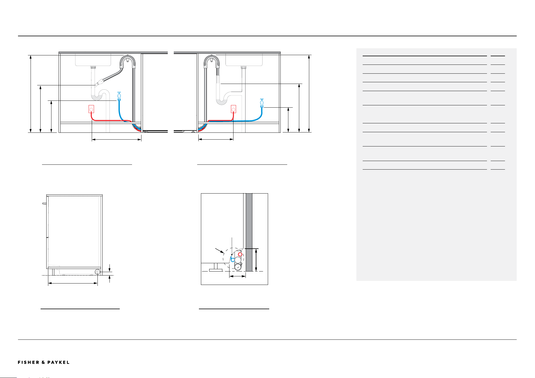
Service placement options
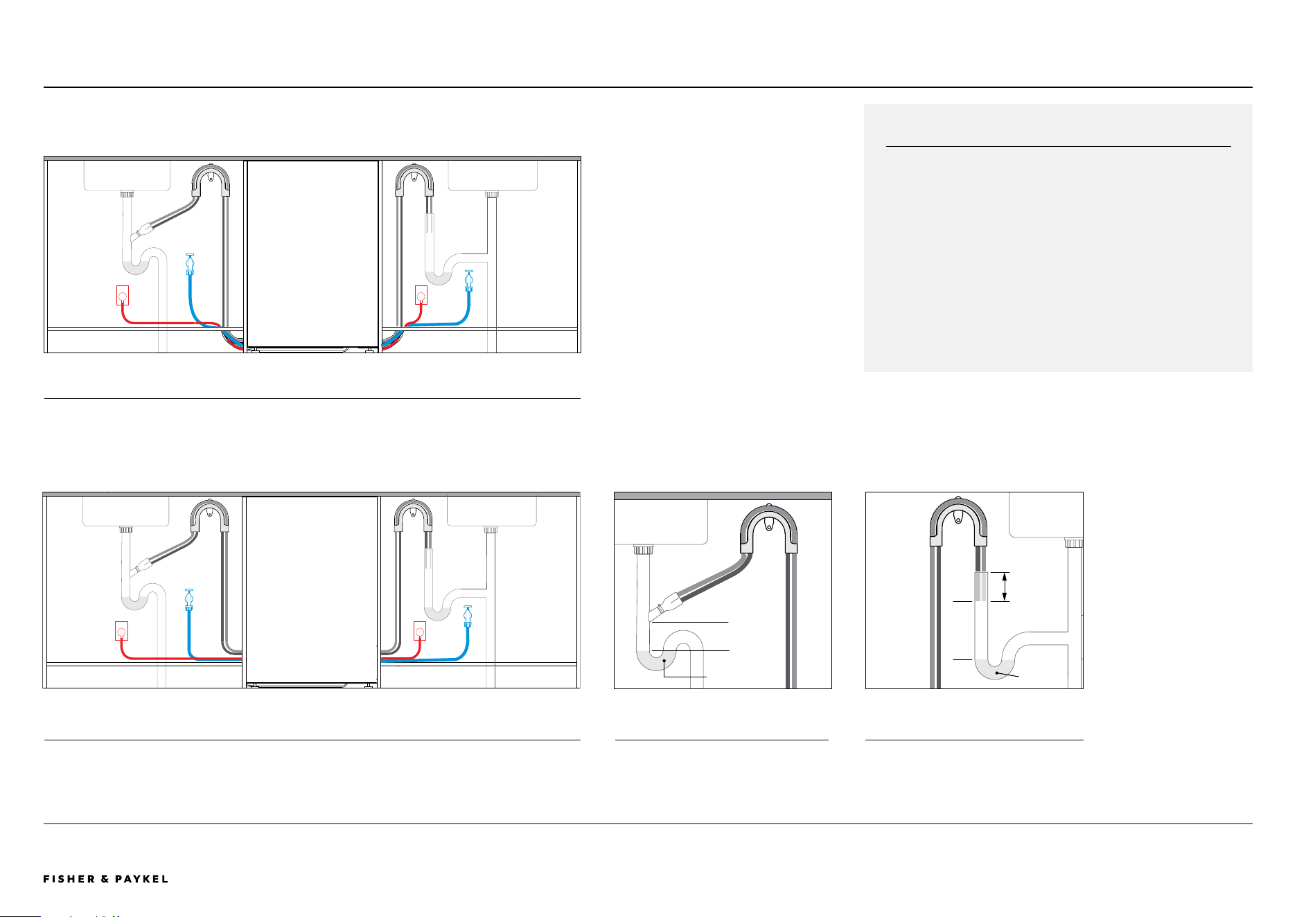
SERVICE REQUIREMENTS
The drain hose support should be placed as close to the
underside of the counter top as possible.
Drain hoses must be installed higher than standing water with an
air gap between to avoid drainage issues.
Hoses can be shortened to achieve the air gap.
Hoses must not extend into a standpipe more than 120mm.
If the drain hoses supplied are not long enough to reach your
services, a Fisher & Paykel drain hose extension kit is available
which will extend the drain hoses by 3.6m (part number 525798).
FRONT SECTION VIEW - SERVICES THROUGH TOE KICK
Services can be routed left or right through the toe kick and into the adjacent cabinet. Drainage can be routed to a
spigot or stand pipe.
FRONT SECTION VIEW - SERVICES THROUGH CABINET SIDE
If routing directly through the cabinet side is necessary, ensure that the service hole is raised. There must be space
behind the dishwasher for feeding hoses and cords.
Max 120mm
Air
Gap
Standing
water
Air
Gap
Standing
water
DETAIL VIEW - STAND PIPE INSTALL
The dishwasher drain must be installed no more
than 120mm into the stand pipe.
An air gap between drain ends and standing
water is required.
DETAIL VIEW - SPIGOT INSTALL
The spigot must be installed above the
standing water with an air gap in between.
<< CONTENTS
The models shown in this Planning Guide may not be available in all markets and are subject to change at any time. Product specifications may vary from those shown. This Planning Guide should not be used as installation guidance for any
product. Further information is required to safely and correctly install the products featured here. Specific installation guidance will be available on our website fisherpaykel.com
© FISHER & PAYKEL LIMITED APPLIANCES 2025 PAGE 2190004476A PLANNING GUIDE DISH - VERSION A - MAY 2025
SERVICES | SERVICE SPECIFICATIONS
Service specifications
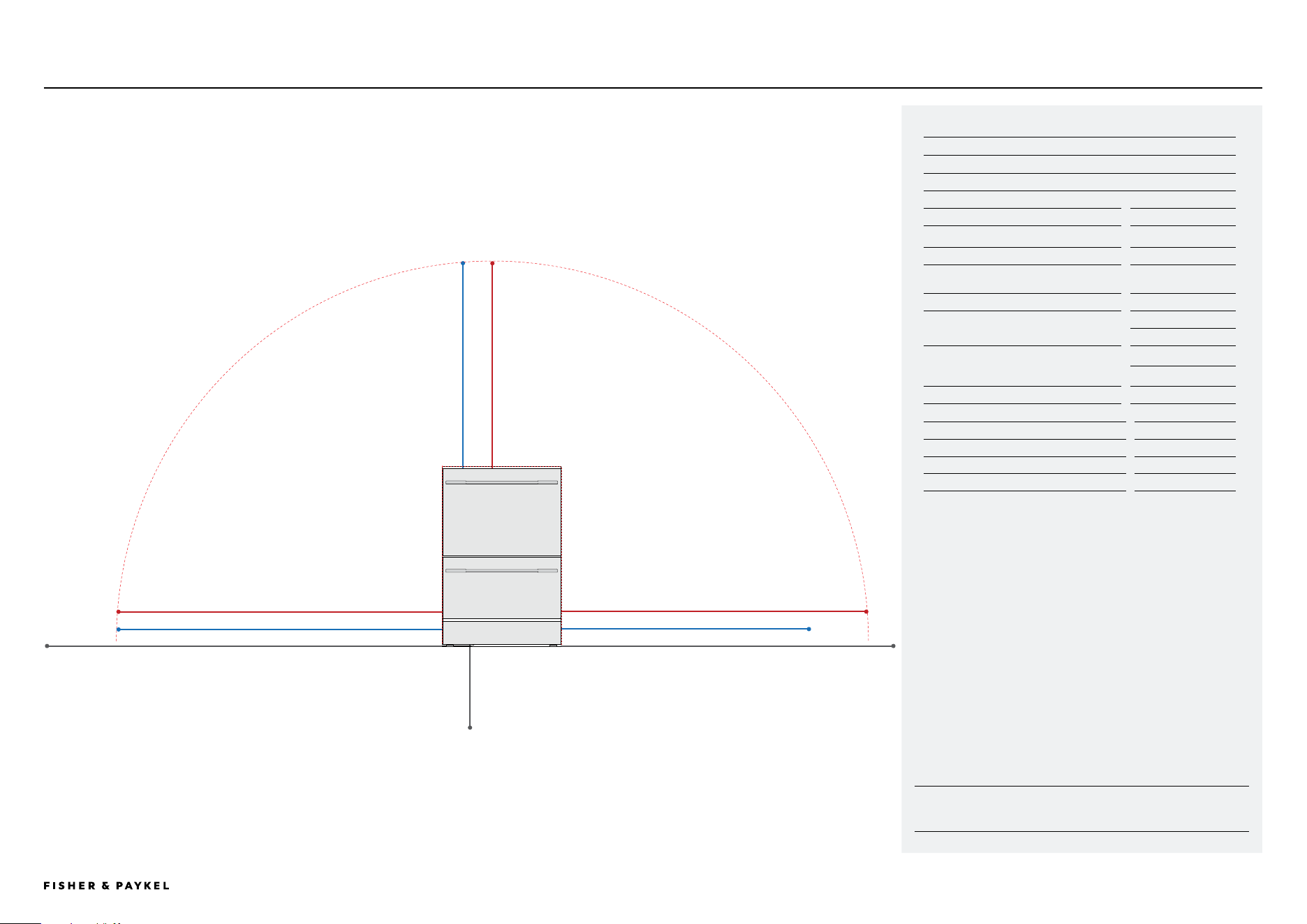
Service dimensions mm
A Minimum distance from floor to top of hose support 750
B Minimum distance from floor to end of drain hoses* 500
C Minimum distance from floor to inlet hose connection 200
D Maximum distance from cabinetry to the centre of
electrical outlet
450
*Distances are the same for standpipe and waste tee
installation.
Minimum service hole dimensions mm
E Minimum distance between front of product* and
center of service hole
538
F Maximum distance between floor and center of
service hole
38
G Minimum diameter of all service holes 57
*Not including dishwasher panels
D
C
B
A
Chassis edge
46mm
63
mm
E
F
G
C
B
A
D
FRONT SECTION VIEW - SPIGOT INSTALL FRONT SECTION VIEW - STAND PIPE INSTALL
SIDE SECTION VIEW - SERVICE HOLE DETAIL 1 - SERVICE HOLE
1
<< CONTENTS
IMPORTANT NOTE: Throughout this guide, dimensions may vary by ±2mm
(1/16''). Please read the Installation Guide for detailed information on
installing the product. For full installation instructions visit fisherpaykel.com
© FISHER & PAYKEL LIMITED APPLIANCES 2025 PAGE 2290004476A PLANNING GUIDE DISH - VERSION A - MAY 2025
SERVICES | ELECTRICAL AND PLUMBING SPECIFICATIONS
Electrical and plumbing specifications
Electrical and plumbing specifications
DD60DTX6I1, DD60DTX6HI1
Electrical
Supply 220 – 240V
Service Min 8.5A
Plumbing
Supply 3/4” BSP (GB20) to
suit flat washer
Pressure
Water softener model (DD60DTX6HI1) Min. 0.1 MPa (14.5 psi)
Max. 1 MPa (145 psi)
Non water softener model (DD60DTX6I1) Min. 0.03 MPa (4.3 psi)
Max. 1 MPa (145 psi)
Recommended temperature Cold (max 60⁰C)
Hose and cord lengths mm
Drain hoses* 2000
Water inlet 1850
Power 1600
*The Fisher & Paykel 3.6m drain hose extension kit (part number
525798) is available for purchase from fisherpaykel.com
Water inlet hose - 1650mm
Power cord (excluding plug) - 1650mm
Drain hose - 2000mm
1250mm - Water inlet hose
1550mm - Power cord (excluding plug)
1700mm - Drain hose
Power cord (excluding plug)
1600mm
Water inlet hose
1850mm
Drain hose
2000mm
<< CONTENTS

PAGE 23© FISHER & PAYKEL APPLIANCES LIMITED 2025PLANNING GUIDE DISH VERSION A - MAY 202590004476A
DATA SHEETS: HANDLES
Data sheets: Handles
IMPORTANT NOTE: Throughout this guide, dimensions may vary by ±2mm
(1/16''). Please read the Installation Guide for detailed information on
installing the product. For full installation instructions visit fisherpaykel.com
© FISHER & PAYKEL LIMITED APPLIANCES 2025 PAGE 2490004476A PLANNING GUIDE DISH - VERSION A - MAY 2025
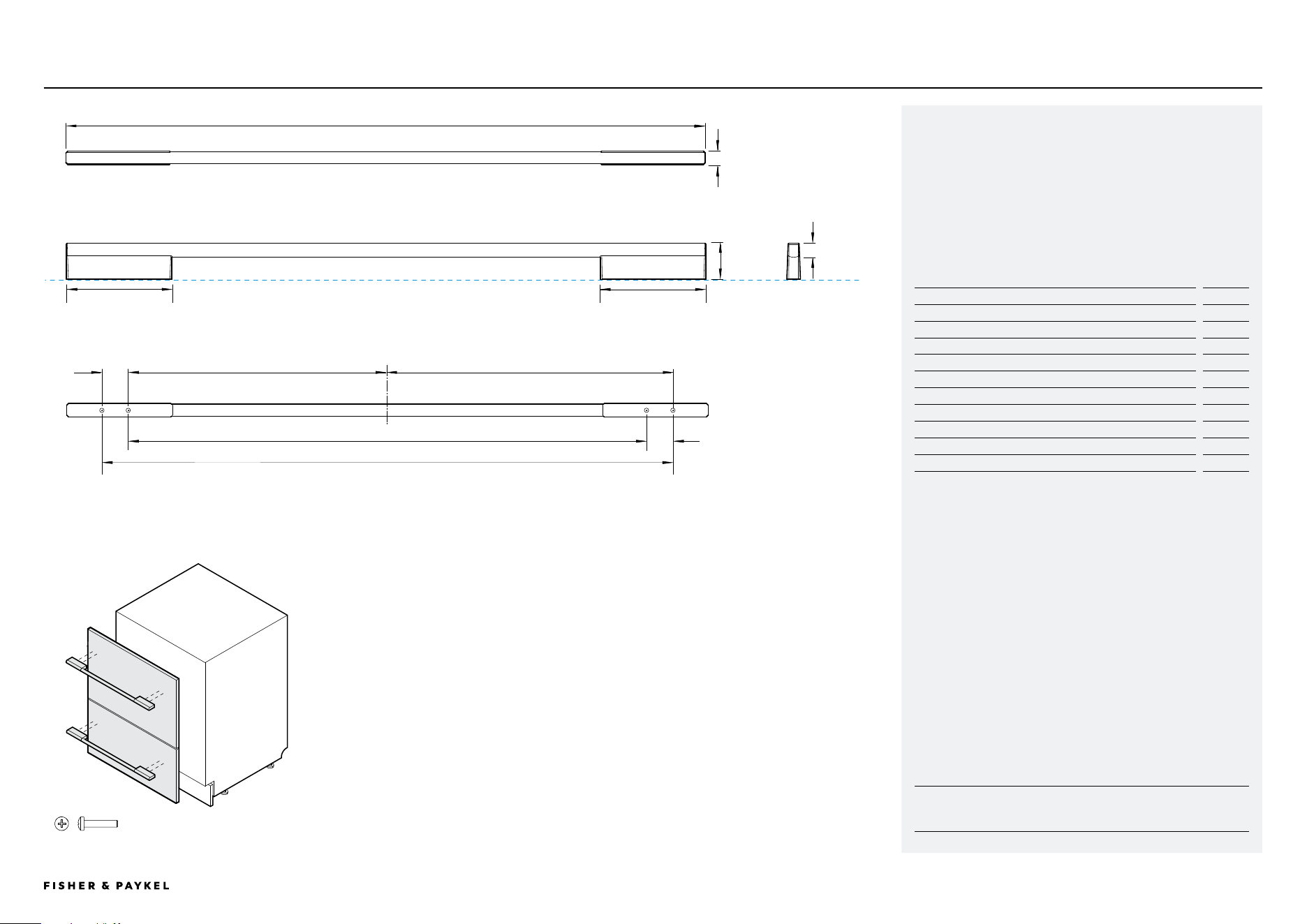
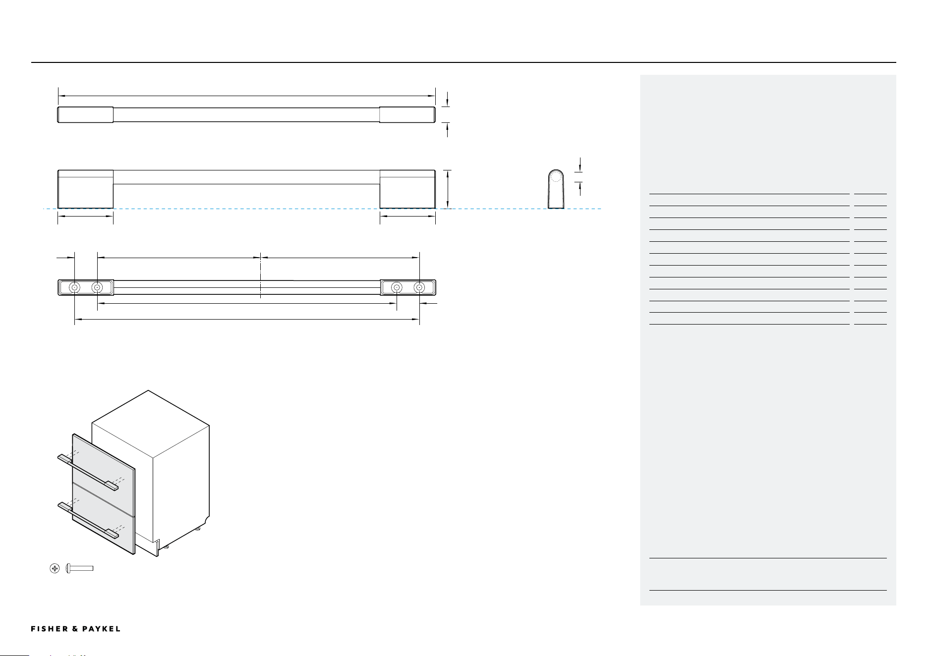
Contemporary square fine handle
DATA SHEET | HANDLES
CONTEMPORARY SQUARE FINE
Model no:
Square Fine Handle AHD5-OBDD-60SX
Black Square Fine Handle AHD5-OBDD-60SB
For Models:
DD60DTX6I1, DD60DTX6HI1, DD60DI9, DD60DHI9
Compatible with drawer panel kits:
Square Fine Handle for drawer Panel Kits ADDD60DPX, ADDD60DTPX
Black Square Fine Handle for drawer Panel Kits ADDD60DPB, ADDD60DTPB
Custom drawer panels
Handle Dimensions
mm
A Overall length of handle
565
B Overall depth of handle
15
C Overall height of handle
41
D Length of off-stand
100
E Distance between attachment holes
32
F Distance from centreline to inner attachment holes
216
G Distance from centreline to outer attachment holes
248.5
H Distance between inner attachment holes
432
I Distance between outer attachment holes
497
J Thickness of handle rail
16
*Suits standard 19mm drawer panel. Thicker drawer panels may require counter
boring or longer screws.
Note: Single Dishwasher requires one handle kit. Double Dishwasher requires
two handle kits.
A
B
C
D D
E
F G
H
I
E
j
*M6 X 25mm Pan Head Socket Screw (2 per handle)
<< CONTENTS
IMPORTANT NOTE: Throughout this guide, dimensions may vary by ±2mm
(1/16''). Please read the Installation Guide for detailed information on
installing the product. For full installation instructions visit fisherpaykel.com
© FISHER & PAYKEL LIMITED APPLIANCES 2025 PAGE 2590004476A PLANNING GUIDE DISH - VERSION A - MAY 2025
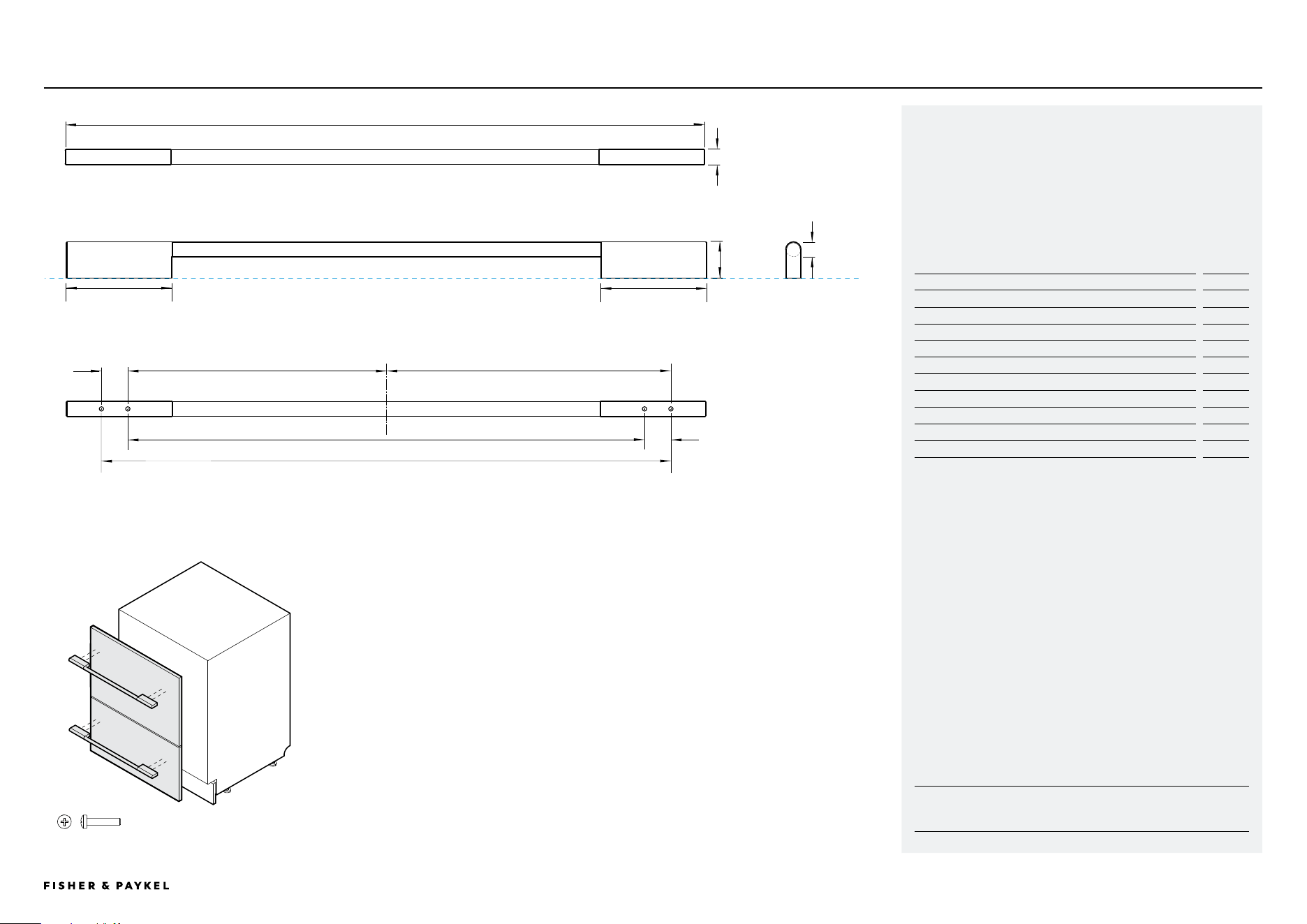
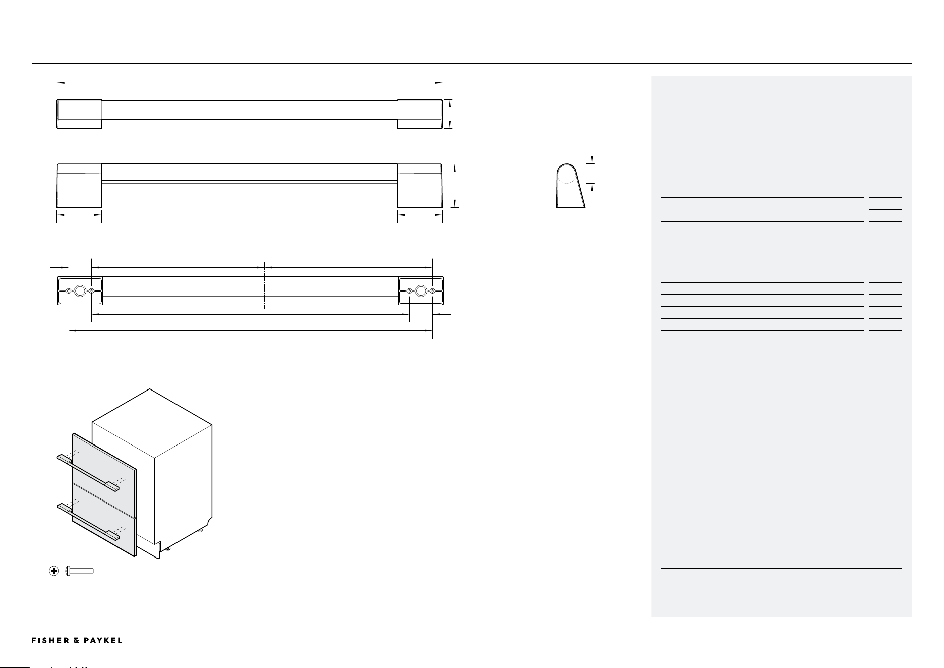
Contemporary round handle
DATA SHEET | HANDLES
CONTEMPORARY ROUND
Model no:
Round Handle AHS-OBDD-60S
For Models:
DD60DTX6I1, DD60DTX6HI1, DD60DI9, DD60DHI9
Compatible with drawer panel kits:
Round Handle for Drawer Panel Kits ADDD60SPX, ADDD60STPX
Handle Dimensions
mm
A Overall length of handle
565
B Overall depth of handle
17
C Overall height of handle
41
D Length of off-stand
100
E Distance between attachment holes
32
F Distance from centreline to inner attachment holes
216
G Distance from centreline to outer attachment holes
248.5
H Distance between inner attachment holes
432
I Distance between outer attachment holes
497
J Thickness of handle rail
16
*Suits standard 19mm drawer panel. Thicker drawer panels may require counter
boring or longer screws.
Note: Single Dishwasher requires one handle kit. Double Dishwasher requires
two handle kits.
A
B
C
D D
E
F G
H
I
E
j
*M6 X 25mm Pan Head Socket Screw (2 per handle)
<< CONTENTS
IMPORTANT NOTE: Throughout this guide, dimensions may vary by ±2mm
(1/16''). Please read the Installation Guide for detailed information on
installing the product. For full installation instructions visit fisherpaykel.com
© FISHER & PAYKEL LIMITED APPLIANCES 2025 PAGE 2690004476A PLANNING GUIDE DISH - VERSION A - MAY 2025
Classic round handle
A
B
C
D D
E
F
G
H
I
E
j
Model no:
Classic Round Handle AHCL-DDDW-60X
For Models:
DD60DTX6I1, DD60DTX6HI1, DD60DI9, DD60DHI9
Compatible with drawer panel kits:
Classic Round Handle for Drawer Panel Kits ADDD60DPX, ADDD60DTPX
Handle Dimensions
mm
A Overall length of handle
544
B Overall depth of handle
22
C Overall height of handle
55
D Length of off-stand
80
E Distance between attachment holes
32
F Distance from centreline to inner attachment holes
216
G Distance from centreline to outer attachment holes
248.5
H Distance between inner attachment holes
432
I Distance between outer attachment holes
497
J Diameter of handle rail
20
*Suits standard 19mm drawer panel. Thicker drawer panels may require counter
boring or longer screws.
Note: Single Dishwasher requires one handle kit. Double Dishwasher requires
two handle kits.
DATA SHEET | HANDLES
CLASSIC ROUND
*M6 X 25mm Pan Head Socket Screw (2 per handle)
<< CONTENTS
IMPORTANT NOTE: Throughout this guide, dimensions may vary by ±2mm
(1/16''). Please read the Installation Guide for detailed information on
installing the product. For full installation instructions visit fisherpaykel.com
© FISHER & PAYKEL LIMITED APPLIANCES 2025 PAGE 2790004476A PLANNING GUIDE DISH - VERSION A - MAY 2025
Professional round flush handle
A
B
C
D D
E
F
G
H
I
E
j
Model no:
Professional Round Flush Handle AHP3-DWDD-60S
For Models:
DD60DTX6I1, DD60DTX6HI1, DD60DI9, DD60DHI9
Compatible with drawer panel kits:
Professional Flush Handle for drawer Panel Kits ADDD60DPX, ADDD60DTPX
Custom Drawer Panels
Handle Dimensions
mm
A Overall length of handle
515
B Overall depth of handle
38
C Overall height of handle
58
D Length of off-stand
60
E Distance between attachment holes
32
F Distance from centreline to inner attachment holes
216
G Distance from centreline to outer attachment holes
248.5
H Distance between inner attachment holes
432
I Distance between outer attachment holes
497
J Diameter of handle rail
25
*Suits standard 19mm drawer panel. Thicker drawer panels may require
counter boring or longer screws.
Note: Single Dishwasher requires one handle kit. Double Dishwasher requires
two handle kits.
DATA SHEET | HANDLES
PROFESSIONAL ROUND FLUSH
*M6 X 25mm Pan Head Socket Screw (2 per handle)
<< CONTENTS

© FISHER & PAYKEL LIMITED APPLIANCES 2025 PAGE 2890004476A PLANNING GUIDE DISH - VERSION A - MAY 2025