
AC-AEX-DEARC-KIT
User Manual
AUDIO EXTENDER KIT FOR ARC & eARC

WWW.AVPROEDGE.COM • 2222 EAST 52
nd
STREET NORTH • SIOUX FALLS, SD 57104 • +1-605-274-6055 2
Contents
Important Safety Instructions ................................................................................................................................................................... 3
Safety Classifications in this Document ........................................................................................................................................ 3
Electrical Shock Prevention ................................................................................................................................................................. 3
Weight Injury Prevention ........................................................................................................................................................................ 3
Safety Statements .................................................................................................................................................................................... 4
Features ......................................................................................................................................................................................................... 5
Product Overview ........................................................................................................................................................................................... 6
Box Contents ............................................................................................................................................................................................... 6
Technical Specifications ........................................................................................................................................................................ 6
Transmitter Front and Rear Panel Overview .............................................................................................................................. 8
Receiver Front and Rear Panel Overview ................................................................................................................................. 10
Wiring and Connections ............................................................................................................................................................................ 12
HDMI Cables .............................................................................................................................................................................................. 12
HB-Link Port (Audio Proprietary Link) Wiring ........................................................................................................................... 12
USB Port ...................................................................................................................................................................................................... 13
RS-232 Wiring and Control ................................................................................................................................................................ 13
IR Wiring ...................................................................................................................................................................................................... 13
Connecting the Devices ............................................................................................................................................................................ 14
Device Configuration .................................................................................................................................................................................. 15
AC-AEX-DEARC-T SETTINGS ................................................................................................................................................................ 15
IR Configuration ............................................................................................................................................................................................. 16
Audio Configuration .................................................................................................................................................................................. 177
AC-AEX-DEARC-R SETTINGS ............................................................................................................................................................. 177
HDMI Audio Configuration ..................................................................................................................................................................... 188
Troubleshooting ............................................................................................................................................................................................. 19
Maintenance ................................................................................................................................................................................................... 19
Damage Requiring Service ................................................................................................................................................................... 200
Support ............................................................................................................................................................................................................ 200
Warranty ......................................................................................................................................................................................................... 200
The Basics .................................................................................................................................................................................................. 20
Coverage Details .................................................................................................................................................................................. 211
Red Tape ..................................................................................................................................................................................................... 21
Obtaining an RMA ................................................................................................................................................................................ 211
Shipping ..................................................................................................................................................................................................... 211
Limitation on Liability .......................................................................................................................................................................... 222
Exclusive Remedy ................................................................................................................................................................................ 222
WWW.AVPROEDGE.COM • 2222 EAST 52
nd
STREET NORTH • SIOUX FALLS, SD 57104 • +1-605-274-6055 3
Important Safety Instructions
Before installing, configuring, and operating this device and other vendor equipment, AVPro Edge
strongly recommends that each dealer, integrator, installer, and all other necessary personnel access
and read all the required technical documentation, which can be located by visiting AVProEdge.com.
Read and understand all safety instructions, cautions, and warnings in this document and the labels on
the equipment.
Safety Classifications in this Document
Note:
Provides special information for installing, configuring, and operating this
device, or this device with associated equipment.
Tip:
Provides suggestions and considerations for installing, configuring, and
operating this device.
Important:
Provides special information that is critical for installing, configuring, and
operating this device, or this device with associated equipment.
Caution:
Provides special information to avoid situations that may result in damage
to the device or associated equipment.
Warning:
Provides special information to avoid situations where improper
installation may endanger the installer, end user, or those unaware.
Electrical Shock Prevention
Electric Shock:
Provides special information critical for installing, configuring, and
operating this device or associated equipment safely.
Electrical Disconnect:
Provides special information to prevent situations that may result in
damage to the device, associated equipment, or pose a personnel hazard.
Weight Injury Prevention
Weight Injury:
Safe installation for some devices may require two-person handling.
Attempts otherwise may result in injury.

WWW.AVPROEDGE.COM • 2222 EAST 52
nd
STREET NORTH • SIOUX FALLS, SD 57104 • +1-605-274-6055 4
Safety Statements
Follow all of the safety instructions listed below and apply them accordingly. Additional safety
information will be included where applicable.
1 Read and keep these instructions.
2 Heed and follow all warnings.
3 Clean devices and equipment only with a dry cloth.
4 Devices not designed for exposure to moisture should
NEVER
be installed in prone locations.
5 Do not block any ventilation openings or install them in a manner cautioned against.
6 This device or accessories should never be exposed to open flames or excessive heat.
7 Only use attachments and accessories specified by AVPro Edge.
8 Install by these instructions provided by AVPro Edge.
9 Do not install near a potential source of inordinate heat that may cause this device to operate
outside its normal thermal capacity.
10 Do not defeat the safety purpose of the polarized/grounding-type plug. A polarized plug has
two blades, one wider than the other. A grounding-type plug has two blades and a third
grounding prong. The wide blade, or third prong, is provided for your safety.
11 Position all device power cords in such a manner that prevent the potential for any sharp
radius bends, particularly where they exit the device or at the mains power connection.
12 Provide proper protection and isolation from dangerous surge conditions and disconnect
devices from power if they are unused for a long period.
13 To reduce the risk of electrical shock, never contact the device or power cord with damp
hands.
14 Safe installation for some devices may require two-person handling. Attempts otherwise may
result in injury.
15
There are NO internal user-serviceable parts
. Should this device function erratically or not
appear to be operating correctly, please contact AVPro Edge Technical Support. If the power
cord/power supply has been compromised, do not attempt or continue operating.
WWW.AVPROEDGE.COM • 2222 EAST 52
nd
STREET NORTH • SIOUX FALLS, SD 57104 • +1-605-274-6055 5
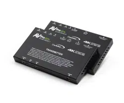
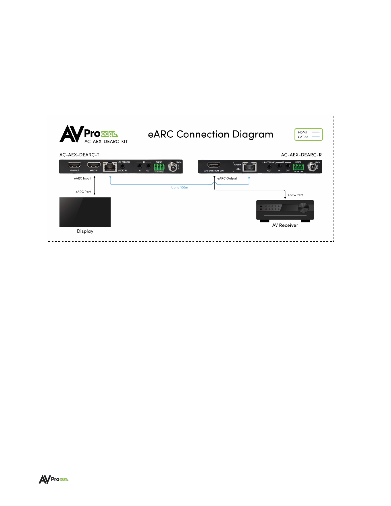
Introduction
The AC-AEX-DEARC-KIT is comprised of the AC-AEX-DEARC-T Transmitter and AC-AEX-DEARC-R
Receiver units. Featuring AP-LINK, AVPro Edge’s proprietary High Bitrate protocol, which combines the
transmission of up to 32 uncompressed audio channels with bi-directional control communication.
Allowing the AC-AEX-DEARC-KIT to extend HDMI eARC, Digital, or Analog audio signals paired with CEC,
RS232, or IR control over 100 meters using a single UTP Category cable.
The diagram below shows the eARC application of the AC-AEXDEARC-KIT.
Features
• Inputs assignable for HDMI eARC/ARC, or External SPDIF, L/R Analog Stereo.
NOTE: This kit does not downmix multichannel audio.
L/R channels are output by the AC-
AEX-DEARC-R receiver per their input status. Stereo may be selectable in the Audio menu of
many displays for dialogue output.
• Provides transfer of multichannel audio codecs or PCM format audio from a display to an
AVR or central system distribution location at distances up to 100m/328ft over Category
cable (Cat 6A recommended).
• Supports high-bitrate audio formats including Dolby Digital, Dolby Digital Plus, Dolby TrueHD,
Dolby Atmos, DTS 5.1, DTS-HD Master Audio, and DTS:X
• Supports ARC and eARC over HDMI
• Bidirectional CEC, IR, and RS-232 Control Signal Transport
• Audio-only HDMI output on AC-AEX-DEARC-T transmitter for local room use
• PoC bidirectional-capable, or powered via a 12VDC adapter
• LED Power, ARC, and eARC status indicator lights

WWW.AVPROEDGE.COM • 2222 EAST 52
nd
STREET NORTH • SIOUX FALLS, SD 57104 • +1-605-274-6055 6
Product Overview
Box Contents
(1x) AC-AEX-DEARC-T (Transmitter)
(1x) AC-AEX-DEARC-R (Receiver)
(1x) 12V-2.0A Power Supply
(2x) 3-Pin Terminal Block Connector for RS-232 Ports
(2x) Mini-TOSLINK connectors
(1x) 3.5mm Mono IR Emitter
(1x) 3.5mm Stereo IR Eye
(4x) Mounting Brackets
(8x) Mounting Screws
Technical Specifications
Video
Video Transport Not Supported
Audio
Audio Formats Supported
(HDMI eARC)
PCM 2.0 Ch, LPCM 5.1 & 7.1, Dolby Digital, Dolby Digital
Plus, Dolby TrueHD, Dolby Atmos, DTS Digital, DTS Hi-Res,
DTS-HD Master Audio, DTS:X
Audio Formats Supported
(SPDIF/ARC)
PCM 2.0 Ch, Dolby Digital, DTS 5.1
Audio Formats Supported
(Analog)
PCM 2.0 (3.4Vpp)
Distance
Category Cabling
100 meters (328ft) Category 6A
Ports
HDMI (Audio-only Output)
Type A
SPDIF
Mini-TOS
Analog
Stereo 3.5 mm
AP-Link
RJ45 with PoC (connect the power supply to the preferred
device to power both devices simultaneously)
IR Send (Tx and Rx)
3.5mm mono jack
IR Receive (Tx and Rx)
3.5mm stereo jack
RS-232 (Tx and Rx)
3-Pin Terminal Block Connector
Power (Tx and Rx)
2-Pin Terminal Block Connector
Environmental
Operating Temperature
23°F (-5°C) to 125°F (51°C)
Storage Temperature
-4°F (-20°C) to 140°F (60°C)
Humidity Range
5% to 90% RH (no condensation)
Power
Power Consumption (total)
24 Watts maximum
Power Supply – Matrix
Input: AC 100-240V ~ 50/60Hz
Output: DC 12V, 2.0A
Dimensions
Height x Width x Depth
(Single Unit)
Millimeters: 15 x 140 x 80
Inches: 0.6 x 5.5 x 3.1
Height x Width x Depth
(Packaged Kit)
Millimeters: 86.4 x 196.8 x 140
Inches: 3.4 x 7.75 x 5.5
Weight
(Single Unit)
0.5 lbs (0.23 kg)

WWW.AVPROEDGE.COM • 2222 EAST 52
nd
STREET NORTH • SIOUX FALLS, SD 57104 • +1-605-274-6055 7
Weight
(Packaged Kit – Shippable Weight)
2 lbs
*Specifications are subject to change without notice. Mass and dimensions are approximate.
WWW.AVPROEDGE.COM • 2222 EAST 52
nd
STREET NORTH • SIOUX FALLS, SD 57104 • +1-605-274-6055 8
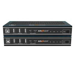
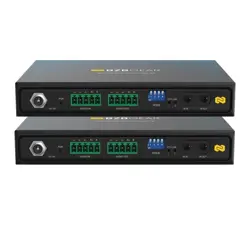
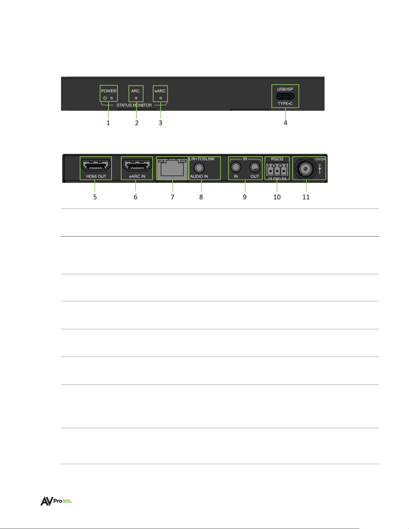
Transmitter Front and Rear Panel Overview
AC-AEX-DEARC-T (Transmitter) – Front Panel
AC-AEX-DEARC-T (Transmitter) – Rear Panel
1
POWER STATUS MONITOR
• Red LED status indicator light
• Illuminates when power is present (PoC or 12V/2A)
2
ARC STATUS MONITOR
• Blue LED status indicator light
• Indicates ARC audio is selected (Analog, SPDIF, ARC)
3
eARC STATUS MONITOR
• Blue LED status indicator light
• Indicates eARC audio is selected
4
USB ISP
• USB Type-C female connector port
• Proprietary servicing port for AVPro Edge Technical Support use
5
HDMI OUT
• HDMI 2.1 Audio-only loop out for local connectivity
• Audio loop out from the eARC HDMI 2.1 input from the TV
6
eARC IN
• HDMI 2.1 Audio-only input
• eARC/ARC Audio from Television eARC/ARC HDMI port
7
AP-LINK
(AUDIO PROPRIETARY LINK)
• 8-pin, RJ-45 female connection port
• Transmission output for proprietary AP-LINK audio and control
signals
• Connects to AC-AEX-DEARC-R using CAT 5e or better
8
L/R+ TOSLINK
AUDIO IN
• Combination 3.5mm TRS and Mini-TOSLINK audio input port
• Accepts Stereo Analog L/R or Digital SPDIF audio signals

WWW.AVPROEDGE.COM • 2222 EAST 52
nd
STREET NORTH • SIOUX FALLS, SD 57104 • +1-605-274-6055 9
9
IR IN & OUT
• 3.5mm TRS connector port (IR In)
• 3.5mm TS connector port (IR Out)
• IR IN accepts IR signals from IR Eye or Control System, dipswitch
selectable
• IR OUT outputs IR Signals from AC-AEX-DEARC-R IR Input
10
RS-232
• 3-pin terminal block connector port
• Control port for serial RS-232 connection
11
12V POWER
• 12V 2A screw-type captive locking barrel power port
• Connects to 12VDC 2A power supply
WWW.AVPROEDGE.COM • 2222 EAST 52
nd
STREET NORTH • SIOUX FALLS, SD 57104 • +1-605-274-6055 10
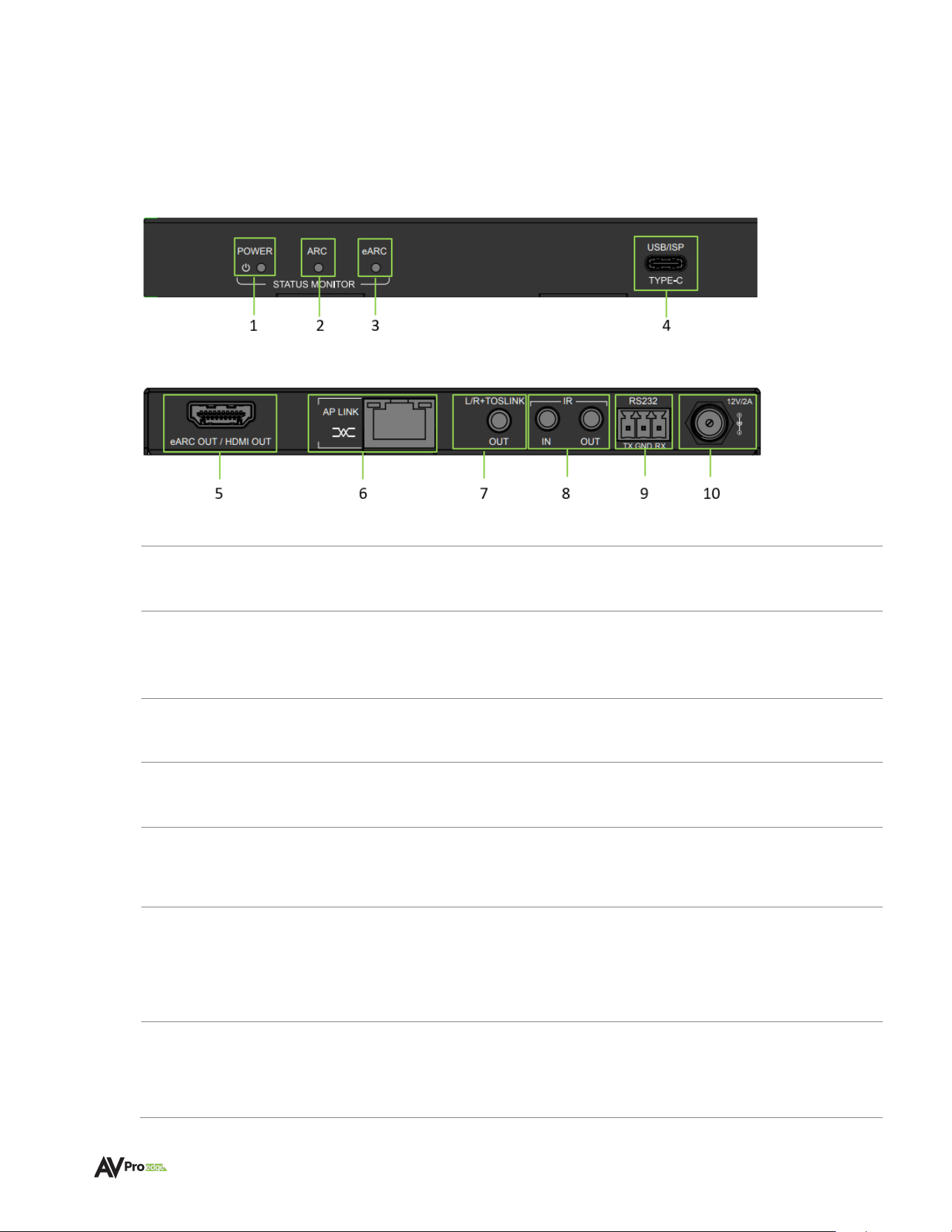
Receiver Front and Rear Panel Overview
AC-AEX-DEARC-R (Receiver) – Front Panel
AC-AEX-DEARC-R (Receiver) – Rear Panel
1
POWER STATUS
MONITOR
• Red LED status indicator light
• Illuminates when power is present (PoC or 12V/2A)
2
ARC STATUS
MONITOR
• Blue LED status indicator light
• Indicates ARC Audio sink is connected
3
eARC STATUS
MONITOR
• Blue LED status indicator light
• Indicates eARC Audio sink is connected
4
USB ISP
• USB Type-C female connector port
• Proprietary servicing port for AVPro Edge Technical Support use
5
eARC OUT /
HDMI OUT
• HDMI 2.1 Audio-only output
• Audio from AC-AEX-DEARC-T
6
AP-LINK
(AUDIO PROPRIETARY LINK)
• 8-pin, RJ-45 female connection port
• Transmission input for proprietary AP-LINK audio and control
signals
• Connects to AC-AEX-DEARC-T using CAT5e (or Better)
7
L/R+ TOSLINK
AUDIO OUT
• Combination 3.5mm TRS and Mini-TOSLINK audio output port
• Outputs Stereo Analog or Digital SPDIF Audio signals from the
AC-AEX-DEARC-T

WWW.AVPROEDGE.COM • 2222 EAST 52
nd
STREET NORTH • SIOUX FALLS, SD 57104 • +1-605-274-6055 11
8
IR IN & OUT
• 3.5mm TRS connector port (IR IN)
• 3.5 mm TS connector port (IR Eye)
• IR IN accepts IR signals from IR Eye or Control System, dipswitch
selectable
• IR OUT outputs IR Signals from AC-AEX-DEARC-T IR Input
9
RS-232
• 3-pin terminal block connector port
• Control port for serial RS-232 connection
10
12V POWER
• 12V 2A screw-type captive locking barrel power port
• Connects to 12VDC 2A power supply
WWW.AVPROEDGE.COM • 2222 EAST 52
nd
STREET NORTH • SIOUX FALLS, SD 57104 • +1-605-274-6055 12
Wiring and Connections
HDMI Cables
The AC-AEX-DEARC-KIT uses the standard 19-pin HDMI female connector port for the inputs and
outputs.
Note:
Ensure all HDMI cables and devices can support the signal being sent. For maximum
performance, an Ultra High Speed HDMI cable rated for 48Gbps is more than sufficient for
high bitrate audio signal transport and will match HDMI cables handling HDMI 2.1a Video
signals.
Tip:
Ensure your HDMI cable is the correct length. The current HDMI specification calls for
cables to be between 2 to 10 meters (6.6 to 33 feet). Smaller gauge HDMI cables may be
unable to transmit higher bandwidth signals such as 4K/60Hz at distances greater than 5
meters (16.5ft).
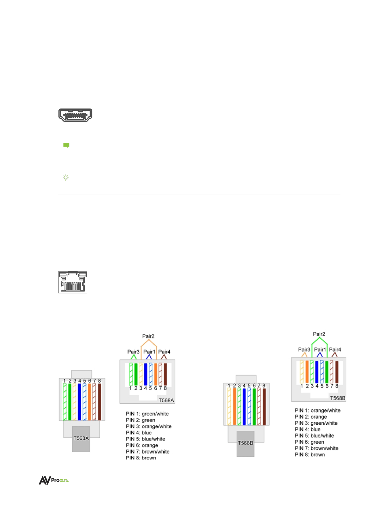
AP-Link Port (Audio Proprietary Link) Wiring
The AP-Link input and output ports on both the Transmitter and Receiver utilize standard RJ-45
connections and feature PoC (Power-over-Cable) capability to supply power to either the Transmitter
or Receiver depending on the device connected to the power supply. Existing Cat 5e cable may be
used however, for maximum performance, recommended cabling is Category 6A UTP. With cabling
rated lower than Cat 5e, kit performance cannot be guaranteed.
The recommended termination is based on TIA/EIA T568A or T568B standards for the wiring of the
twisted pair cables.
T568A
T568B
WWW.AVPROEDGE.COM • 2222 EAST 52
nd
STREET NORTH • SIOUX FALLS, SD 57104 • +1-605-274-6055 13
USB Port
The Type-C USB port on both the Transmitter and Receiver are courtesy ports intended for
troubleshooting purposes when directed by AVPro Edge Technicians. No cables should be
connected to these ports during normal operation.
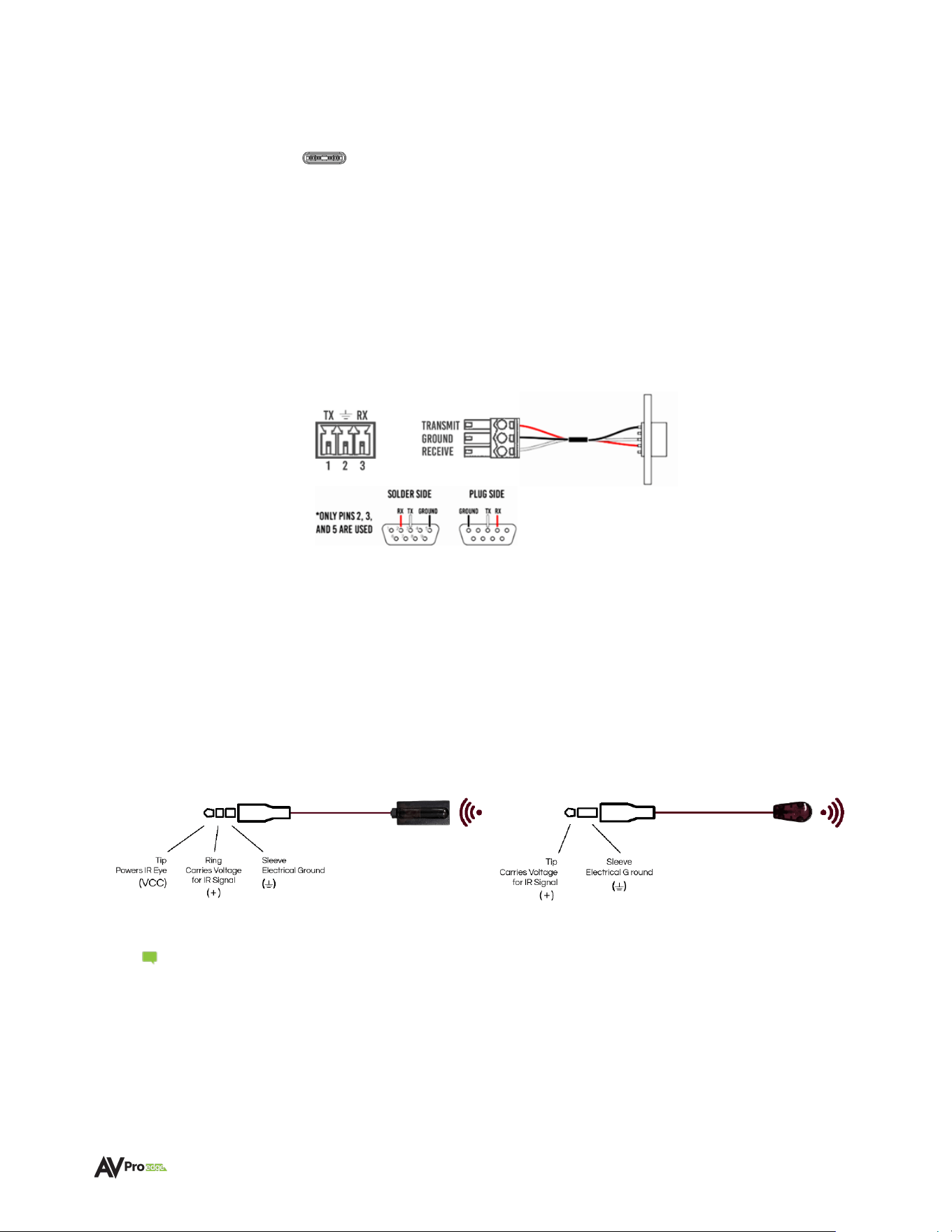
RS-232 Wiring and Control
The RS-232 control ports on both the Transmitter and Receiver are used to pass bidirectional control
signals to and from any RS-232-compatible device.
Serial control connections are made using the provided 3-pin terminal block connector. The wire slips
into the hole and is captively locked by the screw located on the top side of the connector.
Wiring for this port uses a 3-pin terminal block that utilizes pins 2, 3, and 5 when connected to a
standard DB-9 connector. If the control signal device is not equipped with a DB-9 port, use a suitable
adapter for the control device protocol port type required.
IR Wiring
Both the Transmitter and Receiver feature two 3.5mm jack ports for IR management. IR connections
are made using the provided 3.5mm IR Emitter and IR Eye.
AVPro Edge recommends using the supplied IR EYE and IR emitter, as they are designed to correctly
match the voltage parameters of the device IR ports.
Note: The emitter is a NON-VISIBLE type – it does not flash when there is activity.
Stereo 3.5mm (TRS) IR Eye Mono 3.5mm (TS) IR Emitter

WWW.AVPROEDGE.COM • 2222 EAST 52
nd
STREET NORTH • SIOUX FALLS, SD 57104 • +1-605-274-6055 14
Connecting the Devices
1 Connect the Audio Input Source to the desired input on the AC-AEX-DEARC-T, ensure that the
Audio Input Source is turned On. The input types available are:
A – The AC-AEX-DEARC-T eARC input (ARC is also supported) connects to the
Smart TV designated eARC HDMI port via an HDMI cable (not supplied -
an Ultra High Speed HDMI 48Gbps cable is recommended). If using an Active HDMI,
ensure cable is following the correct direction.
B - SPDIF via a TOSLINK cable (not supplied) from the TV’s optical output inserted
into a provided Mini-TOSLINK adapter (supplied), connected to the AC-AEX-DEARC-T
L/R+TOSLINK Audio In port
C – Analog PCM via a 3.5mm analog stereo cable into the AC-AEX-DEARC-T
L/R+TOSLINK Audio In port
Note: The AC-AEX-DEARC-KIT does not perform downmixing, a process that restores
dialogue into the Left and Right stereo channels from multichannel content with
a dedicated Center Channel.
Note: When connecting via Digital TOSLINK or Analog audio, settings in the Audio
Menu of the Smart TV may need to be adjusted so the desired Audio format is
output through these ports.
2 Connect the AC-AEX-DEARC-R to desired Audio Playback Device, ensure that the Audio
Playback Device is turned On.
3 Connect Cat 5e (or better) cabling from the AC-AEX-DEARC-T RJ-45 output port to the RJ-45
input port on the AC-AEX-DEARC-R.
4 Connect the 12V 2A power supply to one unit from the AC-AEX-DEARC-KIT. The companion unit
is automatically powered via the Power-over-Cable feature.
WWW.AVPROEDGE.COM • 2222 EAST 52
nd
STREET NORTH • SIOUX FALLS, SD 57104 • +1-605-274-6055 15
Device Configuration
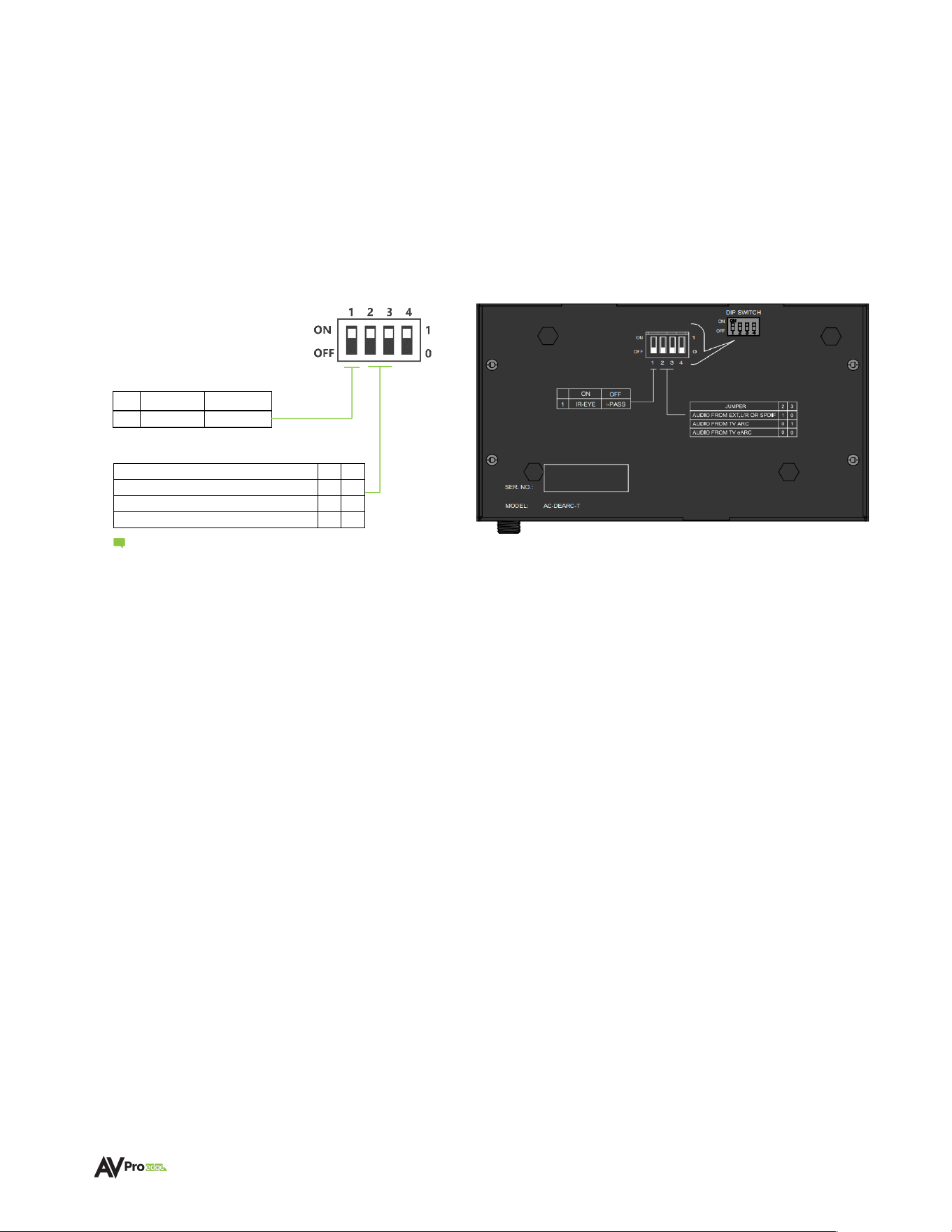
AC-AEX-DEARC-T SETTINGS
Recessed into the bottom casing of the AC-AEX-DEARC-T are 4 dipswitches which are used to
configure the operating parameters of the unit. Each dipswitch/dipswitch combination controls a
different aspect of unit operation.
1
=
Up
(ON)
0
=
Down
(OFF)
ON
OFF
1
IR-EYE
I-PASS
IR CONFIGURATION
DIPSWITCH 1 – The IR IN port is selectable for use between the following two functions:
A - 0 (DEFAULT) – IR EYE
• IR-EYE places the port into an active state, providing power for an IR Sensor “Eye”.
• IR signals from an IR Sensor “Eye” are passed to the AC-AEX-DEARC-R IR Out port.
• Commands from a programmable Smart TV remote can control non-localized devices,
such as an AVR.
• Connect the provided IR receiver eye cable to the IR-IN port of the transmitter to pass
infrared signals generated from remote controls.
B -1 (I-PASS)
• Power to the port is switched off and the port reverts to a conventional passive state.
• IR commands (such as those from popular compact, single-room control systems that
may be located behind a Smart TV) pass back to the AC-AEX-DEARC-R through the
Category cabling, to control devices like CATV or DSS boxes.
• Connect a 3.5mm mono jack (TS) cable into an emitter port of a control system directly
into the IR IN
port on the AC-AEX-DEARC-T to pass IR signals directly to the AC-AEX-
DEARC-R IR OUT port.
JUMPER
2
3
AUDIO FROM EXT. L/R OR SPDIF
1
0
AUDIO FROM TV ARC
0
1
AUDIO FROM TV eARC
0
0
Note: Dipswitch #4 is reserved for future use
WWW.AVPROEDGE.COM • 2222 EAST 52
nd
STREET NORTH • SIOUX FALLS, SD 57104 • +1-605-274-6055 16
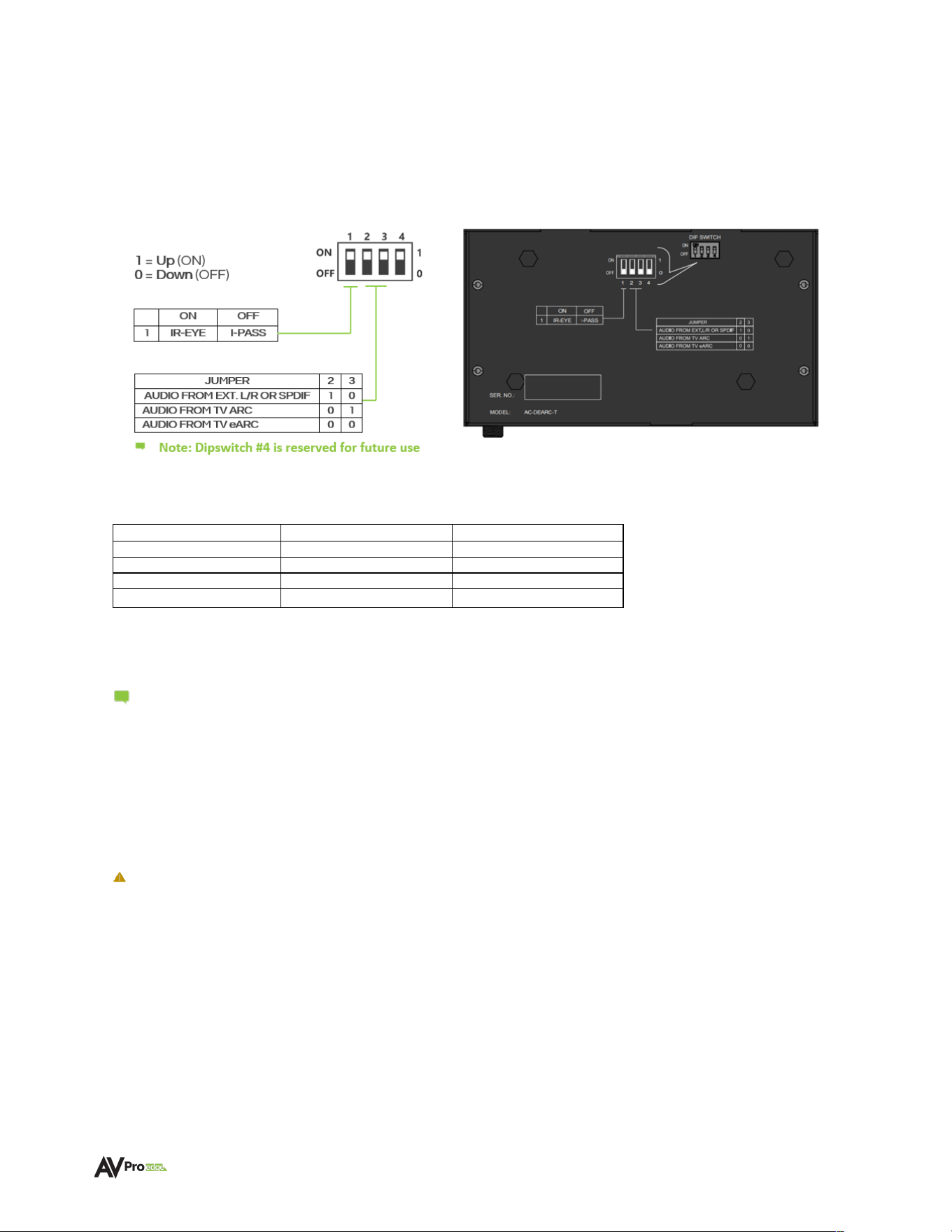
AC-AEX-DEARC-T SETTINGS
AUDIO CONFIGURATION
DIPSWITCHES 2 & 3
TABLE 1
SOURCE
DIPSWITCH 2
DIPSWITCH 3
ANALOG / SPDIF
1
0
FROM TV ARC
0
1
AUDIO FROM TV eARC
0
0
RESERVED (FUTURE USE)
1
1
Use dipswitch positioning in Table 1 to select the audio input format the AC-AEX-DEARC-T will pass to the
AC-AEX-DEARC-R downstream. The AC-AEX-DEARC-R features Dual Play technology that will output the
selected signal from both the eARC OUT/HDMI OUT Audio port and from the L/R+TOSLINK output port.
Note: Audio menu settings in the Smart TV will determine the audio format to be sent to
the AC-AEX-DEARC-KIT. For example, selecting 2-Channel PCM Stereo will send a
combined Left and Right audio mix through BOTH eARC/ARC and the TOSLINK (if
equipped) and analog audio (if equipped) outputs. Selecting passthrough for Digital
CODECS will result in multichannel (and 3D immersive objects) sent to the audio outputs
of the AC-AEX-DEARC-R. eARC/ARC information will pass through the eARC OUT/
HDMI OUT ports, however, what is passed from the L/R+TOSLINK port cannot be
assured.
Important:
As the AC-AEX-DEARC-KIT does not perform audio downmixing if eARC/ARC is
selected for audio output, the audio information that will be output from the
L/R+TOSLINK port will be whatever content is present on the multichannel Left and
Right channels. On some content, this may include dialogue that appears normal
however for other content, it may be sound effects channel information.
WWW.AVPROEDGE.COM • 2222 EAST 52
nd
STREET NORTH • SIOUX FALLS, SD 57104 • +1-605-274-6055 17
Device Configuration
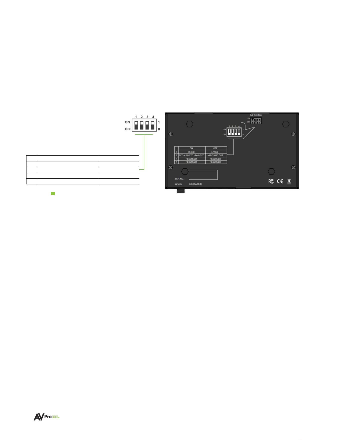
AC-AEX-DEARC-R SETTINGS
Recessed into the bottom casing of the AC-AEX-DEARC-R are 4 dipswitches which are used to
configure the operating parameters of the unit. Each dipswitch/dipswitch combination controls a
different aspect of unit operation.
Note: Dipswitches #3 and #4 are
reserved for future use.
IR CONFIGURATION
DIPSWITCH 1 – The IR IN port is selectable for use between the following two functions:
A - 0 (DEFAULT) – IR EYE
• IR-EYE places the port into an active state, providing power for an IR Sensor “Eye”.
• IR signals from an IR Sensor “Eye” are passed to the AC-AEX-DEARC-T IR Out port.
• Commands from a programmable Smart TV remote can control non-localized devices,
such as an AVR.
• Connect the provided IR receiver eye cable to the IR-IN port of the transmitter to pass
infrared signals generated from remote controls.
B -1 (I-PASS)
• Power to the port is switched off and the port reverts to a conventional passive state.
• IR commands (such as those from control systems) pass upstream to the AC-AEX-
DEARC-T through the Category cabling, to control the Smart TV.
• Connect a 3.5mm mono jack (TS) cable into an emitter port of a control system directly
into the IR IN
port on the AC-AEX-DEARC-R to pass IR signals directly to the AC-AEX-
DEARC-T IR OUT port.
ON
OFF
1
IR-EYE
I-PASS
2
EXT. AUDIO TO HDMI OUT
EARC/ARC OUT
3
RESERVED
RESERVED
4
RESERVED
RESERVED
TABLE 2

WWW.AVPROEDGE.COM • 2222 EAST 52
nd
STREET NORTH • SIOUX FALLS, SD 57104 • +1-605-274-6055 18
AC-AEX-DEARC-R SETTINGS
HDMI AUDIO CONFIGURATION
DIPSWITCH 2 – Use to select between eARC audio output or conventional HDMI audio-only outputs:
A - 0 (DEFAULT) – eARC OUT
• The HDMI port operates as an eARC/ output with compatible devices such as AVRs or
Pre-amp processors.
B -1 (HDMI OUT)
• The HDMI port operates as a conventional HDMI audio-only output for any playback
device equipped with an HDMI input
.
DIPSWITCH 4 – This switch is reserved for future use and should remain in the default OFF (down) position.

WWW.AVPROEDGE.COM • 2222 EAST 52
nd
STREET NORTH • SIOUX FALLS, SD 57104 • +1-605-274-6055 19
Troubleshooting
• Verify Power – Check that the power supply is properly connected and is outputting 12V.
• Verify Connections – Check that all cables are properly connected and/or terminated where
applicable.
• Verify Terminations – Ensure you are using a minimum of CAT 5e UTP or STP without breaks such
as keystones, punch downs, or other interconnectors. Field terminatable plugs are
recommended.
• IR Not Passing – Ensure the provided AVPro Edge IR emitter and IR EYE are being utilized and
are connected to the appropriate port.
• No Audio – Ensure the desired input is selected by the dipswitch settings.
• No Audio - Ensure the audio is not exceeding the desired AC-AEX-DEARC-R connection (for
example, an eight-channel 3D immersive codec attempting to play through the TOSLINK digital
output).
• No Power-over-Cable – Switch the 12V power supply to the opposite device to see if that corrects
the issue.
• No Power-over-Cable – Ensure the Category cable run has not suffered damage.
• No Power-over-Cable – Ensure the Category cable distance has not exceeded 100m/328Ft.).
Maintenance
To ensure the reliable operation of these devices as well as protection for the safety of any person using
or handling these devices while powered, observe the following instructions:
• Use the provided power supplies. If an alternative power supply is required, check the voltage and
polarity to ensure it has sufficient power to supply the device it is connected to.
• Do not operate these devices outside the specified temperature and humidity range given in the
above specifications.
• Ensure there is adequate ventilation to allow these devices to operate efficiently.
• Repair of the equipment should only be carried out by qualified professionals as these devices
contain sensitive components that may be damaged by any mistreatment.
• Only use these devices in a dry environment. Do not allow any liquids or harmful chemicals to
come into contact with these devices.
• Clean this unit with a soft, dry cloth. Never use alcohol, paint thinner, or benzene to clean these
devices.

WWW.AVPROEDGE.COM • 2222 EAST 52
nd
STREET NORTH • SIOUX FALLS, SD 57104 • +1-605-274-6055 20
Damage Requiring Service
These devices should be serviced only by AVPro Edge qualified personnel if:
• Objects or liquids have breached the interior of the devices
• The devices have been exposed to rain or moisture
• The devices do not operate normally or exhibit a marked change in performance
• The devices have been dropped or the housing is damaged
• Replace the DC power supply cord or AC adapter if they have suffered damage
Support
Should you experience any problems using this product, first refer to the Troubleshooting section of this
manual before contacting AVPro Technical Support. When calling in, the following information should be
provided:
• Product name and model number
• Product serial number
• Details of the issue and any conditions under which the issue is occurring
Warranty
The Basics
AVPro Edge warranties its products that are purchased from all authorized AVPro Edge resellers or
direct purchases. Products are guaranteed to be free from manufacturing defects and are of sound
physical and electronic condition.
AVPro Edge has developed a warranty that anyone can get behind. We wanted to take all the “red
tape” out of a warranty and just make it simple. Our 10 Year No BS Warranty hinges on 3 elements:
• If you are having trouble, call us. We will attempt to troubleshoot your issue over the phone.
• If it’s broken, we will replace it in advance on our dime and we’ll also cover the return shipping.
Repair is an option too, but it’s YOUR call.
• We know you know what you are doing. We will not make you go through unnecessary steps
to troubleshoot an extender.

WWW.AVPROEDGE.COM • 2222 EAST 52
nd
STREET NORTH • SIOUX FALLS, SD 57104 • +1-605-274-6055 21
Coverage Details
AVPro Edge will replace or repair (at the customer’s choice) defective products. If the product is out of
stock or on backorder it can be replaced with a comparable product of equal value/feature set (if
available) or repaired.
Your warranty begins at receipt of the product (as confirmed by shipping firm tracking). If tracking
information is unavailable for any reason, the warranty will commence 30 days ARO (After Receipt of
Order). The coverage continues for 10 years.
Red Tape
AVPro Edge is not responsible for untraceable purchases or those that were made outside of an
authorized channel.
If we conclude that a product or serial number has been tampered with as identified by the warranty
seal or physical examination, the warranty will be void. Additionally, if it has been determined the
failure is due to excessive physical damage (beyond normal wear & tear), the warranty may be voided
or prorated, based on the extent of the damage as examined by an AVPro Edge representative.
Damages caused by “acts of God” are not covered. This includes but is not limited to natural
disasters, power surges, storms, earthquakes, tornados, sinkholes, typhoons, tidal waves, hurricanes,
or any other uncontrollable nature-related event.
Damage caused by incorrect installation will not be covered. Use of a different or incorrect power
supply, inadequate cooling, improper cabling, inadequate protection, and static discharge are
examples of this.
Products installed or sold by a third party to AVPro Edge will be serviced by the authorized AVPro
Edge reseller. Accessories (IR cables, RS-232, power supplies, etc.) are not included in the warranty.
We will make acceptable efforts to source and supply replacements for defective accessories at a
discounted rate as needed.
Obtaining an RMA
Dealers, resellers, and installers can request an RMA from an AVPro Edge Technical Support
representative or Sales Engineer. Or you may email [email protected] or fill out the general
contact form at www.avproedge.com/contact.
End users may not request an RMA directly from AVPro Edge and will be referred back to the dealer,
reseller, or installer.
Shipping
For the USA (not including Alaska and Hawaii), shipping is covered on advanced replacements for
FedEx Ground (some expressed exceptions may apply). Defective product return shipping is covered
by AVPro Edge using an emailed return label. Items must be returned within 30 days of receipt of the
replacement product, after 40 days the customer will be billed. Other return shipping methods will not
be covered.
For international (and Alaska and Hawaii) return shipping costs will be the responsibility of the
returnee. Once the unit is scanned for return shipping AVPro Edge will ship the new replacement unit.

WWW.AVPROEDGE.COM • 2222 EAST 52
nd
STREET NORTH • SIOUX FALLS, SD 57104 • +1-605-274-6055 22
Limitation on Liability
The maximum liability of AVPro Global Holdings LLC under this limited warranty shall not exceed the
actual purchase price paid for the product. AVPro Global Holdings LLC is not responsible for direct,
special, incidental, or consequential damages resulting from any breach of warranty or condition, or
under any other legal theory to the maximum extent permitted by law. Taxes, Duties, VAT, and other
freight forwarding service charges are not covered or paid for by this warranty.
Obsolescence or incompatibility with newly invented technologies (after the manufacture of these
products) is not covered by this warranty. Obsolescence is defined as:
Peripherals are rendered obsolete when current technology does not support product repair or re-
manufacture. Obsolete products cannot be re-manufactured because advanced technologies
supersede original product manufacturer capabilities. Because of performance, price, and
functionality issues, product re-development is not an option.
Discontinued or out-of-production items will be credited at fair market value towards a current
product of equal or comparable capabilities and cost. Fair market value is determined by AVPro
Edge.
Exclusive Remedy
To the maximum extent permitted by law, this limited warranty and the remedies set forth above are
exclusive and in lieu of all other warranties, remedies, and conditions, whether oral or written, express
or implied. To the maximum extent permitted by law, AVPro Global Holdings LLC specifically disclaims
any and all implied warranties, including, without limitation, warranties of merchantability and fitness
for a particular purpose. If AVPro Global Holdings LLC cannot lawfully disclaim or exclude implied
warranties under applicable law, then all implied warranties covering this product, including
warranties of merchantability and fitness for a particular purpose, shall apply to this product as
provided under applicable law.
This warranty supersedes all other warranties, remedies, and conditions, whether oral or written,
express or implied.