ARUF**14** / ASPT**14**
AIR HANDLERS INSTALLATION &
OPERATING INSTRUCTIONS
CONTENTS
1 Important Safety Instructions .................................... 1
2 Shipping Inspection ................................................... 3
2.1 Parts ...................................................................... 3
2.2 Handling ................................................................ 3
3 Codes & Regulations ................................................. 3
4 Replacement Parts ..................................................... 3
5 Pre-Installation Considerations ................................ 3
5.1 Preparation ............................................................ 3
5.2 System Matches .................................................... 3
5.3 Interconnecting Tubing .......................................... 3
5.4 Clearances ............................................................ 3
5.5 Horizontal Applications .......................................... 3
6 Installation Location ................................................... 3
6.1 Upow Installation ................................................. 4
6.2 Horizontal Left Installation ..................................... 4
6.3 Horizontal Right Installation /
Downow Installation ............................................. 5
7 Refrigerant Lines ........................................................ 6
7.1 Tubing Size ............................................................ 6
7.2 Tubing Preparation ................................................ 6
7.3 Special Instructions ............................................... 6
7.4 Tubing Connections for Flowrator Model ............... 8
7.5 Tubing Connections for TXV Models ..................... 8
7.6 ASPT**14** Models with Non-Adjustable TXV ...... 8
7.7 Thermal Expansion Valve System Adjustment ...... 9
8 Condensate Drain Lines ........................................... 10
9 Ductwork .................................................................... 10
9.1 Return Ductwork ........................................................ 11
10 Return Air Filters ..................................................... 11
11 Electric Heat ............................................................. 11
12 Electrical and Control Wiring ................................. 12
12.1 Building Electrical Service Inspect ...................... 12
12.2 Wire Sizing.......................................................... 12
12.3 Maximum Overcurrent Protection (MOP) ........... 12
12.4 Electrical Connections – Supply Voltage ............ 14
12.4.1 Air Handler Only (Non-Heat Kit Models) ..... 14
12.4.2 Air Handler - Non-Circuit Breaker Heat Kits 14
12.4.3 Air Handler With Circuit Breaker Heat Kit ... 14
12.5 Low Voltage Connections ................................... 14
12.5.1 Thermostats ................................................ 14
12.6 Speed Tap Adjustment........................................ 14
13 Achieving 1.4% Low Leakage Rate ....................... 15
14 Start-Up Procedure................................................... 15
15 Regular Maintenance ............................................... 15
16 Airow Data ............................................................... 16
17 Air Handler Low Voltage Connections .................... 18
18 Wiring Diagrams ....................................................... 19
19 Start-Up Checklist .................................................... 27
© 2014-2018, 2020-2022 Goodman Manufacturing Company, L.P.
19001 Kermier Rd., Waller, TX 77484
www.goodmanmfg.com -or- www.amana-hac.com
P/N: IO-901M Date: June 2022
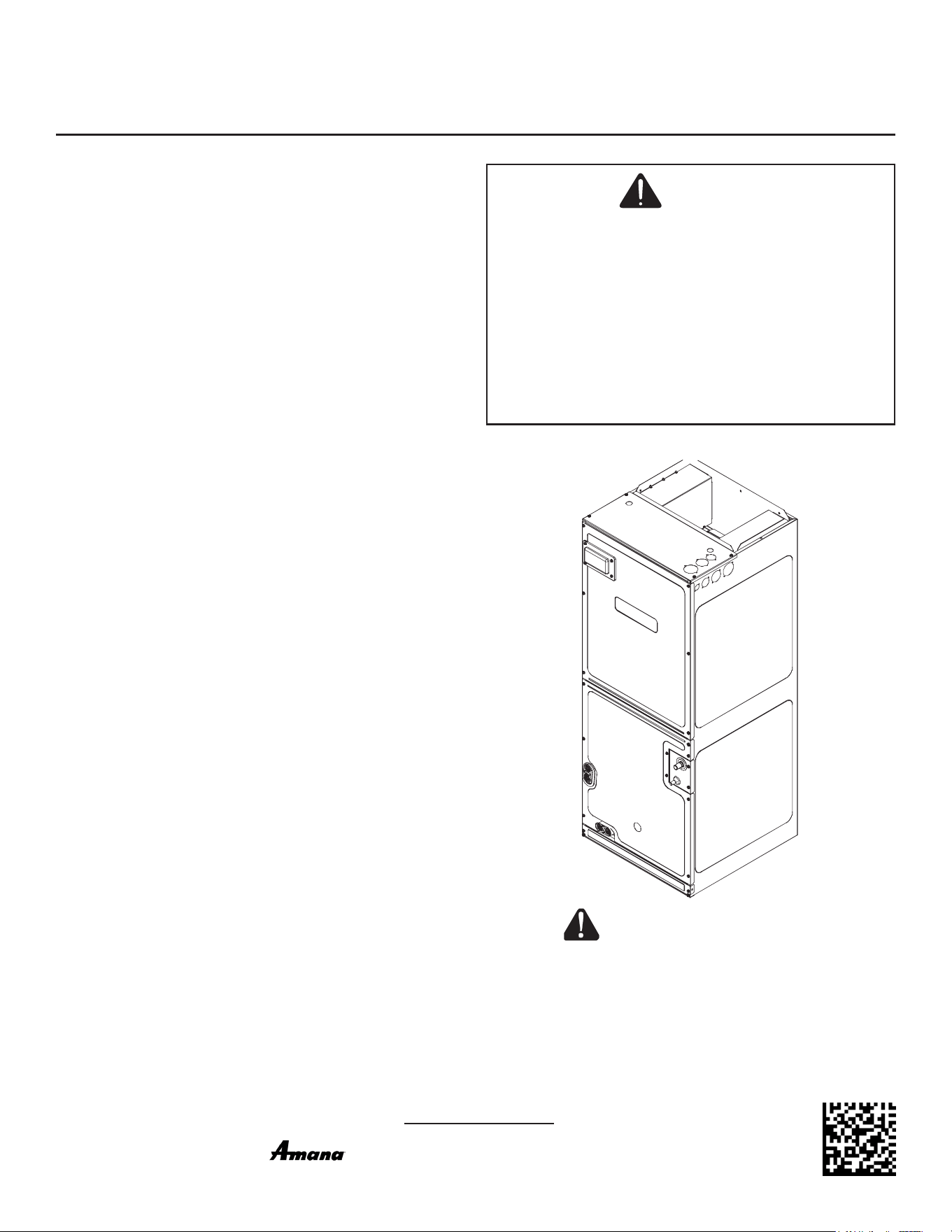
RECOGNIZE THIS SYMBOL
AS A SAFETY PRECAUTION.
Only personnel that have been trained to install, adjust, service
or repair(hereinafter, “service”) the equipment specied in this
manual should service the equipment. The manufacturer will not
be responsible for any injury or property damage arising from im-
proper service or service procedures. If you service this unit, you
assume responsibility for any injury or property damage which
may result. In addition, in jurisdictions that require one or more
licenses to service the equipment specied in this manual, only
licensed personnel should service the equipment.
Improper installation, adjustment, servicing or repair of the equip-
ment specied in this manual, or attempting to install, adjust,
service or repair the equipment specied in this manual without
proper training may result in product damage, property damage,
personal injury or death.
WARNING
is a registered trademark of Maytag Corporation or its related
companies and is used under license. All rights reserved.
NOTE: SPECIFICATIONS AND PERFORMANCE DATA LISTED HEREIN
ARE SUBJECT TO CHANGE WITHOUT NOTICE
2
WARNING
HIGH VOLTAGE
DISCONNECT ALL POWER BEFORE SERVICING
OR INSTALLING THIS UNIT. MULTIPLE POWER
SOURCES MAY BE PRESENT. FAILURE TO DO
SO MAY CAUSE PROPERTY DAMAGE, PERSON-
AL INJURY OR DEATH.
WARNING
TO PREVENT THE RISK OF PROPERTY DAMAGE, PERSONAL
INJURY, OR DEATH, DO NOT STORE COMBUSTIBLE MATERI-
ALS OR USE GASOLINE OR OTHER FLAMMABLE LIQUIDS OR
VAPORS IN THE VICINITY OF THIS UNIT.
WARNING
THIS PRODUCT IS FACTORY-SHIPPED FOR USE WITH
208/240/1/60 ELECTRICAL POWER SUPPLY. DO NOT RECON-
FIGURE THIS AIR HANDLER TO OPERATE WITH ANY OTHER
POWER SUPPLY.
CAUTION
WHEN INSTALLING OR SERVICING THIS EQUIPMENT, SAFE-
TY CLOTHING, INCLUDING HAND AND EYE PROTECTION, IS
STRONGLY RECOMMENDED. IF INSTALLING IN AN AREA THAT
HAS SPECIAL SAFETY REQUIREMENTS (HARD HATS, ETC.),
OBSERVE THESE REQUIREMENTS.
WARNING
TO AVOID PROPERTY DAMAGE, PERSONAL INJURY OR DEATH
DUE TO ELECTRICAL SHOCK, THIS UNIT MUST HAVE AN UNIN-
TERRUPTED, UNBROKEN ELECTRICAL GROUND. THE ELEC-
TRICAL GROUND CIRCUIT MAY CONSIST OF AN APPROPRI-
ATELY SIZED ELECTRICAL WIRE CONNECTING THE GROUND
LUG IN THE UNIT CONTROL BOX TO THE BUILDING ELECTRI-
CAL SERVICE PANEL.
OTHER METHODS OF GROUNDING ARE PERMITTED IF PER-
FORMED IN ACCORDANCE WITH THE NATIONAL ELECTRIC
CODE (NEC) / AMERICAN NATIONAL STANDARDS INSTITUTE
(ANSI) / NATIONAL FIRE PROTECTION ASSOCIATION (NFPA)
70 AND LOCAL/STATE CODES. IN CANADA, ELECTRICAL
GROUNDING IS TO BE IN ACCORDANCE WITH THE CANADIAN
ELECTRIC CODE (CSA) C22.1.
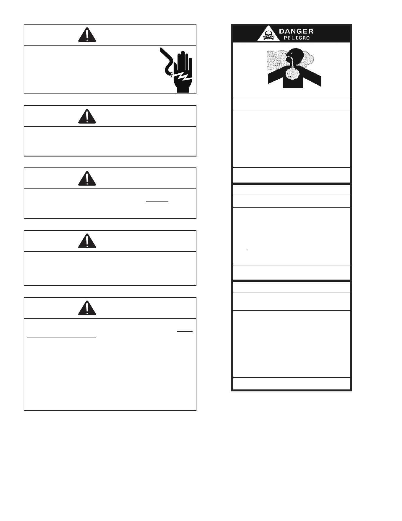
Carbon monoxide producing devices (such as an automobile, space
heater, gas water heater, etc.) should not be operated in enclosed areas
such as unvenlated garages, ulity rooms or parking areas because of
the danger of carbon monoxide (CO) poisoning resulng from the exhaust
emissions. If a furnace or air handler is installed in an enclosed area such
as a garage, ulity room or parking area and a carbon monoxide producing
device is operated therein, there must be adequate, direct outside
venlaon.
CARBON MONOXIDE POISONING HAZARD
Special Warning for In stallaon of Furnace or Air Handling Units in
Enclosed Areas such as Garages, Ulity Rooms or Parking Areas
This venlaon is necessary to avoid the danger of CO poisoning which
can occur if a carbon monoxide producing device connues to operate in
the enclosed area. Carbon monoxide emissions can be (re)circulated
throughout the structure if the furnace or air handler is operang in any
mode.
B10259-216
CO can cause serious illness including permanent brain
damage or death.
Los equipos ó aparatos que producen monóxido
(tal como automóvil, calentador de gas, calentador de
carbono (CO) que resulta de las
emisiones de gases de combusón.
gas, etc) no deben ser operados en áreas cerradas debido al riesgo
de envenenamiento por monóxido de
Si el equipo ó aparato se opera en
dichas áreas, debe exisr una adecuada venlación directa al exterior.
de carbono
agua por medio de
Advertencia especial para la instalación de calentadores ó manejadoras
de aire en áreas cerradas como estacionamientos ó cuartos de servicio.
B10259-216
RIESGO DE INTOXICACIÓN POR MONÓXIDO DE CARBONO
El monóxido de carbono puede causar enfermedades severas
como daño cerebral permanente ó muerte.
Las emisiones de monóxido de carbono pueden circular a través
del aparato cuando se opera en cualquier modo.
Averssement special au sujet de l'installaon d'appareils de chauffage
ou de traitement d'air dans des endroits clos, tets les garages, les
locaux d'entreen et les staonnements.
B10259-216
RISQUE D'EMPOISONNEMENT AUMONOXYDE DE CARBONE
Evitez de mere en marche les appareils produisant du monoxyde
de carbone (tels que les automobile, les appareils de chauffage
autonome,etc.) dans des endroits non venlés tels que les
d'empoisonnement au monoxyde de carbone. Si vous devez faire
fonconner ces appareils dans un endroit clos, assures-vous
qu'il y ait une venlaon directe provenant de l'exterier.
Le monoxyde de
des
carbone peut causer des maladies graves telles que
dommages permanents au cerveau et meme la mort.
Les émissions de monoxyde de carbone peuvent etre recircules dans les
endroits clos, si l'appareil de chauffage ou de traitement d'air sont
en marche.
Cee venlaon est nécessaire pour éviter le danger d'intoxicaon
au CO pouvant su rvenir si un appareil produisant du monoxyde
de carbone connue de fonconner au sein de la zone confinée.
Esta venlación es necesaria para evitar el peligro de envenenamiento
por CO, que puede ocurrir si un monóxido
de carbono sigue operando en el lugar cerrado.
disposivo que produc e
1 Important Safety Instructions
The following symbols and labels are used throughout this
manual to indicate immediate or potential safety hazards.
It is the owner’s and installer’s responsibility to read and
comply with all safety information and instructions accom-
panying these symbols. Failure to heed safety information
increases the risk of personal injury, property damage, and/
or product damage.

3
2 Shipping Inspection
Always transport the unit upright; laying the unit on its side
or top during transit may cause equipment damage. The in-
staller should inspect the product upon receipt for shipping
damage and subsequent investigation is the responsibility
of the carrier. The installer must verify the model number,
specications, electrical characteristics, and accessories
are correct prior to installation. The distributor or manufac-
turer will not accept claims from dealers for transportation
damage or installation of incorrectly shipped units.
2.1 Parts
Also inspect the unit to verify all required components
are present and intact. Report any missing components
immediately to the manufacturer or to the distributor.
Use only factory authorized replacement parts (see
Section 5). Make sure to include the full product model
number and serial number when reporting and/or ob-
taining service parts.
2.2 Handling
Use caution when transporting / carrying the unit. Do not
move unit using shipping straps. Do not carry unit with
hooks or sharp objects. The preferred method of carry-
ing the unit after arrival at the job site is to carry via a
two-wheel hand truck from the back or sides or via hand
by carrying at the cabinet corners.
3 Codes & Regulations
This product is designed and manufactured to comply with appli-
cable national codes. Installation in accordance with such codes
and / or prevailing local codes / regulations is the responsibility
of the installer. The manufacturer assumes no responsibility for
equipment installed in violation of any codes or regulations.
The United States Environmental Protection Agency
(EPA) has issued various regulations regarding the in-
troduction and disposal of refrigerants. Failure to fol-
low these regulations may harm the environment and
can lead to the imposition of substantial nes. Should
you have any questions please contact the local oce of the
EPA and / or refer to EPA’s website www.epa.gov.
4 Replacement Parts
When reporting shortages or damages, or ordering repair
parts, give the complete product model and serial numbers
as stamped on the product. Replacement parts for this prod-
uct are available through your contractor or local distributor.
For the location of your nearest distributor consult the white
business pages, the yellow page section of the local tele-
phone book or contact:
HOMEOWNER SUPPORT
GOODMAN MANUFACTURING COMPANY, L.P.
19001 KERMIER ROAD
WALLER, TEXAS 77484
(855) 770-5678
5 Pre-Installation Considerations
5.1 Preparation
Keep this document with the unit. Carefully read all in-
structions for the installation prior to installing product.
Make sure each step or procedure is understood and
any special considerations are taken into account be-
fore starting installation. Assemble all tools, hardware
and supplies needed to complete the installation. Some
items may need to be purchased locally. Make sure ev-
erything needed to install the product is on hand before
starting.
5.2 System Matches
The entire system (combination of indoor and outdoor
sections) must be manufacturer approved and Air-Con-
ditioning, Heating, and Refrigeration Institute (AHRI)
listed. NOTE: Installation of unmatched systems is not
permitted.
5.3 Interconnecting Tubing
Give special consideration to minimize the length of re-
frigerant tubing when installing air handlers. Refer to Re-
mote Cooling / Heat Pump Service Manual RS6200006,
and TP-107 Long Line Set Application R-410A for tubing
guidelines. If possible, allow adequate length of tubing
such that the coil may be removed (for inspection or
cleaning services) from the cabinet without disconnect-
ing the tubing.
5.4 Clearances
The unit clearance from a combustible surface may be
0”. However, service clearance must take precedence. A
minimum of 24” in front of the unit for service clearance
is required. Additional clearance on one side or top will
be required for electrical wiring connections. Consult all
appropriate regulatory codes prior to determining nal
clearances. When installing this unit in an area that may
become wet (such as crawl spaces), elevate the unit
with a sturdy, non-porous material. In installations that
may lead to physical damage (i.e. a garage) it is advised
to install a protective barrier to prevent such damage.
Always install units such that a positive slope in conden-
sate line (1/4” per foot) is allowed.
5.5 Horizontal Applications
If installed above a nished living space, a secondary
drain pan (as required by many building codes), must be
installed under the entire unit and its condensate drain
line must be routed to a location such that the user will
see the condensate discharge.
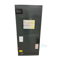
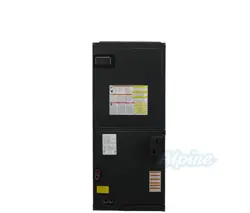
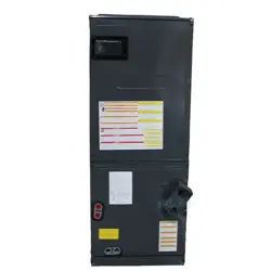
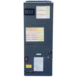
6 Installation Location
NOTE: These air handlers are designed for indoor instal-
lation only.
4
The ARUF**14** and ASPT**14** product lines may be in-
stalled in one of the upow, downow, horizontal left or hori-
zontal right orientations as shown in Figures 2, 3, 4 and 5. The
unit may be installed in upow or horizontal left orientation as
shipped (refer to specic sections for more information).
No eld modications are mandatory. However, to obtain
maximum eciency, the horizontal drip shield, side drain
pan and drain pan extension can be removed.
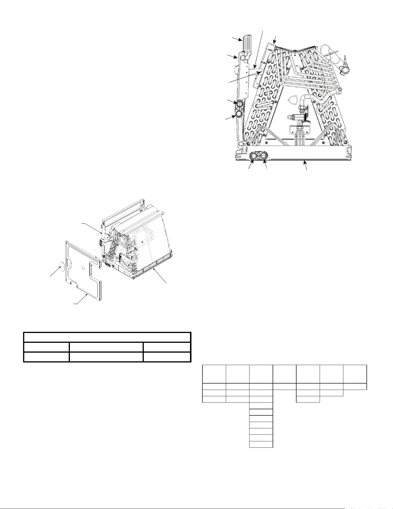
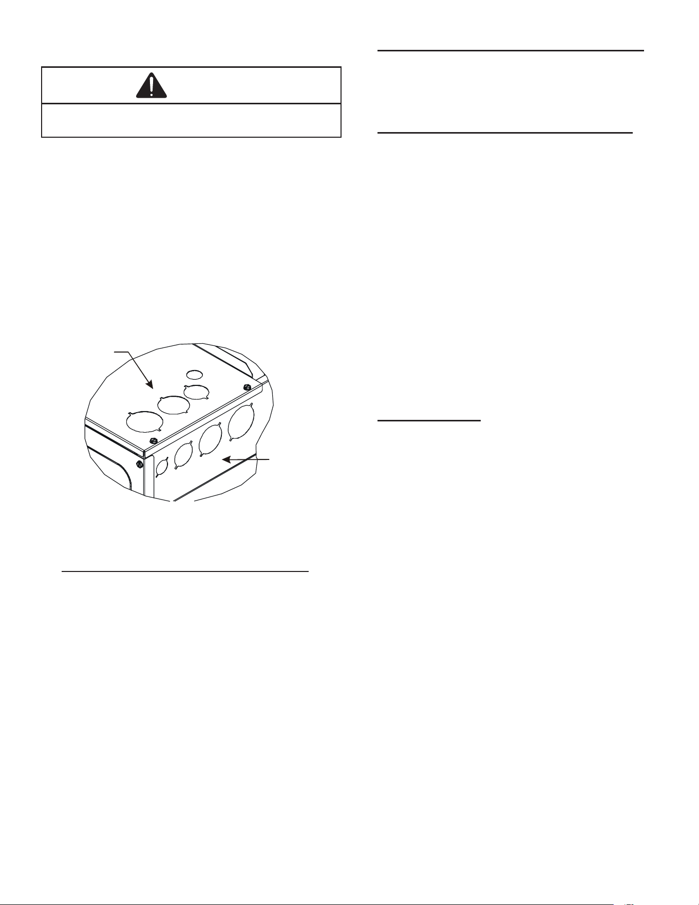
Side Drain Pan and Extension Removal: Refer to Figure
1, remove the two (2) screws that secure the drip shield sup-
port brackets to the condensate collectors (front and back).
Unsnap the side drain pan from the bottom drain pan using
a screw driver or any small lever. The side drain pan, drip
shield brackets and the drain pan extension may now be re-
moved. From Figure 1, drain port labeled (A) is the primary
drain for this application and condensate drain line must be
attached to this drain port. Drain port (a) is for the second-
ary drain line (if used). If the side drain pan is removed, the
drain port opening in the access panel must be covered by
the accessory drain port plug (DPK1) as shown in gure 1.1.
SIDE DRAIN PAN
DPK1 DRAIN PLUG
COIL ACCESS PANEL
MAIN DRAIN PAN
DRAIN PAN
Figure 1.1
Kit Number Application
DPK1 All Models
Side Drain Port Plug
Description
Drain Port Plug
DRAIN PORT PLUG KIT
Table 1
D
rip Pan
E
xtension
Side
Drain
Pan
Screw
B
b
A
Main Drain Pan
Drip Shield Bracket
Drip Shield
Pna
SIDE DRAIN PAN REMOVAL
Figure 1
6.1 Upow Installation
No eld modications are mandatory.
6.2 Horizontal Left Installation
No eld modications are permissible for this application.
Install unit as shown in Figure 4.
Remove red plugs from side drain pan before connecting
condensate drain pipes. Use removed plug to close drain
ports on vertical drain pan. The bottom right drain connec-
tion in side drain pan is the primary drain for this application
and condensate drain line must be attached to this drain
connection. The bottom left drain connection in side drain
pan is for the secondary drain line (if used).
In applications where the air handler is installed in the hor-
izontal left position, and the return air environment see hu-
midity levels above 65% relative humidity coupled with to-
tal external static levels above 0.5” e.s.p., a condensate kit
is available for eld application. Kit nomenclature can be
found in Table 2.
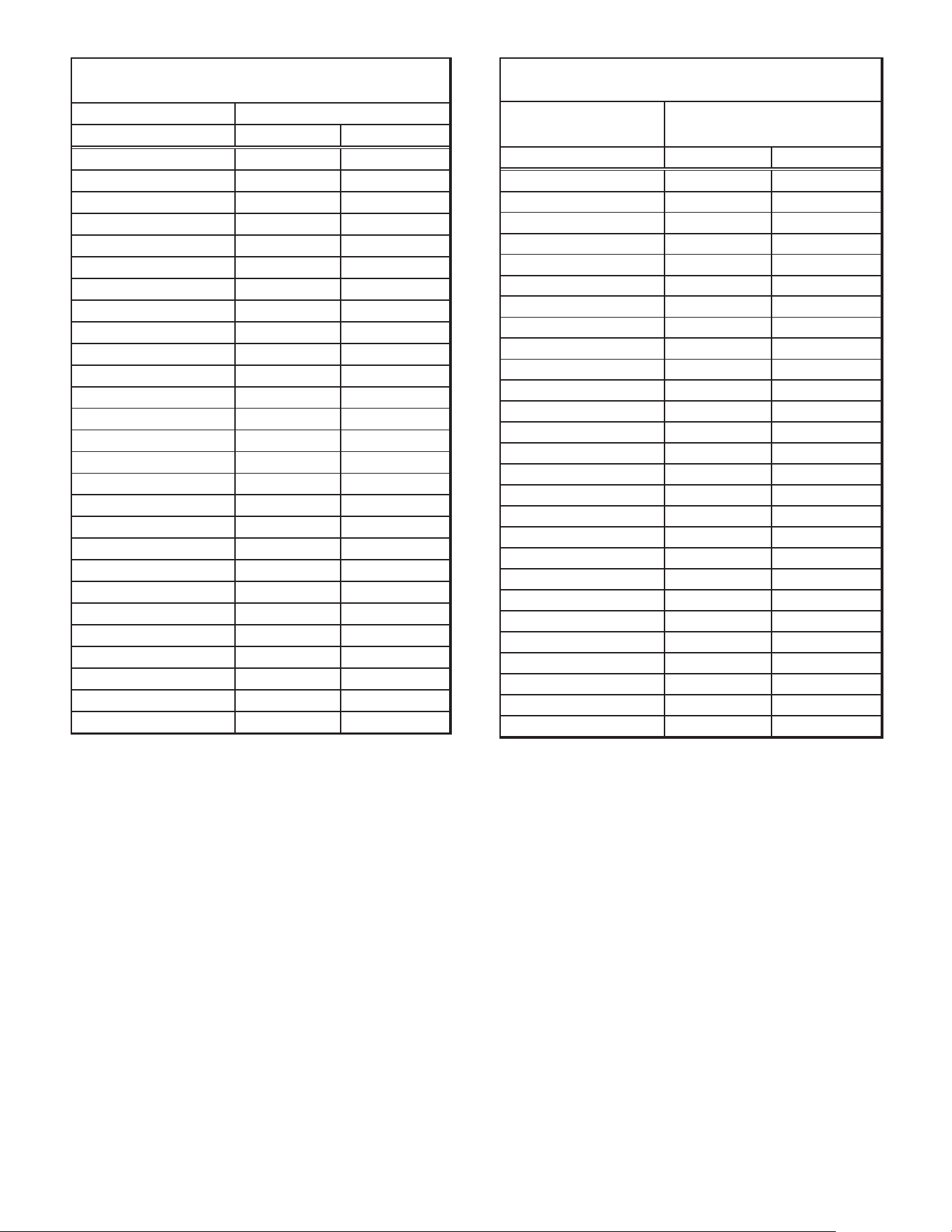
CMK0008
Condensate
Kit
CMK0009
Condensate
Kit
CMK0010
Condensate
Kit
CMK0011
Condensate
Kit
CMK0012
Condensate
Kit
CMK0013
Condensate
Kit
CMK0014
Condensate
Kit
ARUF25B14 ARUF31B14 ARUF37C14 ARUF47D14 ARUF61D14 ASPT33C14 ASPT49C14
ARUF29B14 ASPT29B14 ARUF37D14 ASPT49D14 ASPT39C14
ASPT25B14 ASPT37B14 ARUF43C14 ASPT61D14
ARUF43D14
ARUF49C14
ARUF49D14
ASPT37C14
ASPT47C14
ASPT47D1 4
ASPT59C14
CONDENSATE KIT
Table 2
5
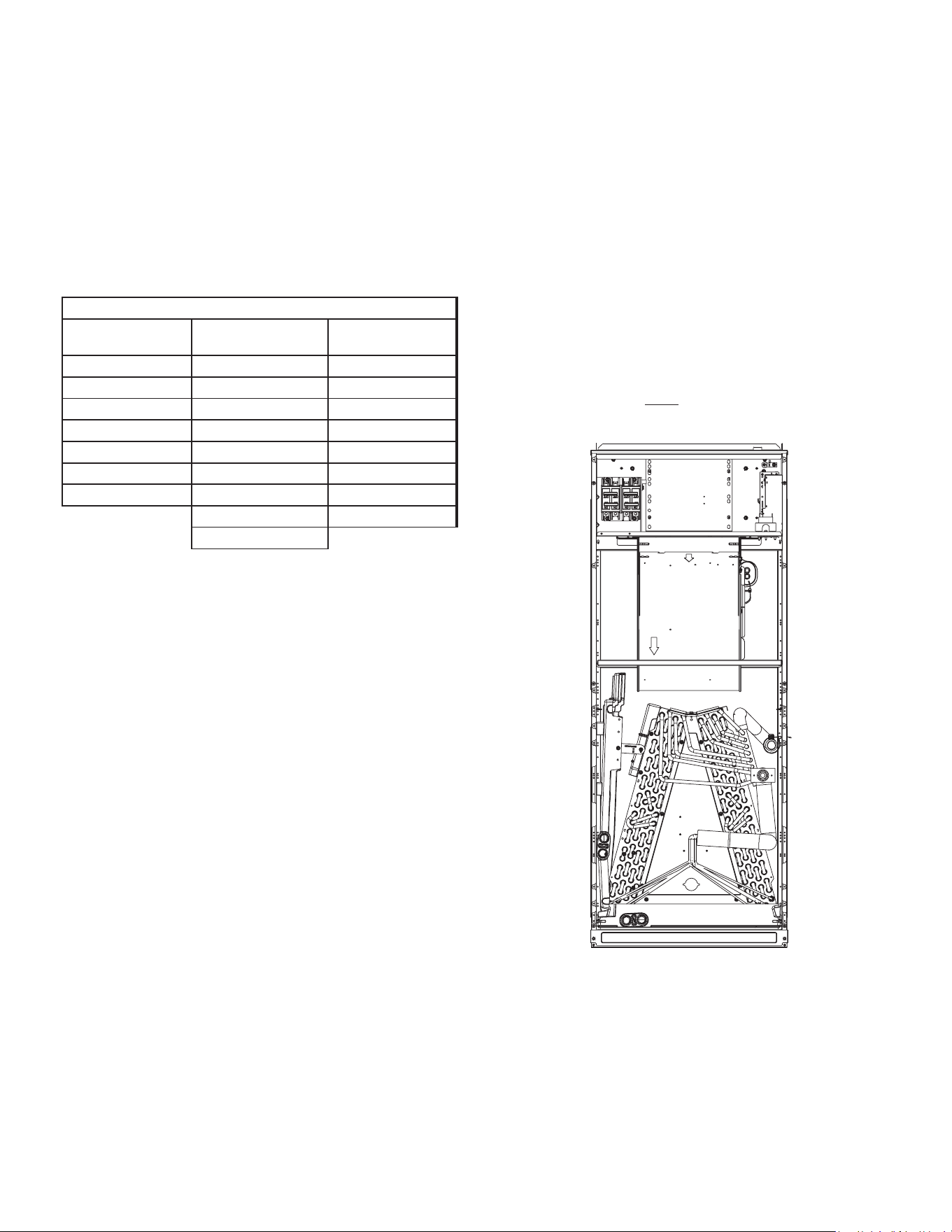
6.3 Horizontal Right Installation / Downow Installation
When installing unit in the downow position the appropriate
(DFK) downow kit is required to prevent “coil pan sweating”.
The DFK kit is not supplied with the air handler and is avail-
able through your local distributor. See Table 3 for the correct
DFK and follow the instructions provided for installation.
Side drain pan extension must be removed in the downow
and horizontal right applications for all models except: ARUF-
47D14**,ARUF61D14**, ASPT61D14**, ASPT49D14**.
Refer to Figure 6 and 7 for the location of the components
referenced in the following steps.
DFK-B
DOWNFLOW KIT
DFK-C
DOWNFLOW KIT
DFK-D
DOWNFLOW KIT
ARUF25B14** ARUF37C14** ARUF37D14**
ARUF29B14** ARUF43C14** ARUF43D14**
ARUF31B14** ARUF49C14** ARUF47D14**
ASPT25B14** ASPT33C14** ARUF49D14**
ASPT29B14** ASPT37C14** ARUF61D14**
ASPT35B14** ASPT39C14** ASPT61D14**
ASPT37B14** ASPT47C14** ASPT47D14**
ASPT49C14** ASPT49D14**
ASPT59C14**
MODEL LIST FOR DOWNFLOW KIT
DOWNFLOW KIT
Table 3
1. Before inverting the air handler, remove blower access
panel and coil access panel. The coil access panel and
tubing panel may remain screwed together during this
procedure. Remove and retain the seven (7) screws se-
curing the coil access panel to the cabinet and the six (6)
screws securing the blower access panel to the cabinet.
2. Slide the coil assembly out from the cabinet. Use the
drain pan to pull the assembly from the cabinet.
NOTE: DO NOT USE MANIFOLDS OR FLOWRA-
TOR TO PULL THE COIL ASSEMBLY OUT. FAIL-
URE TO DO SO MAY RESULT IN BRAZE JOINT
DAMAGE AND LEAKS.
3. Removal of the center support is required on units
with 21” wide cabinet. Remove and retain the two (2)
screws that secure the center support to the cabinet.
Remove the center support.
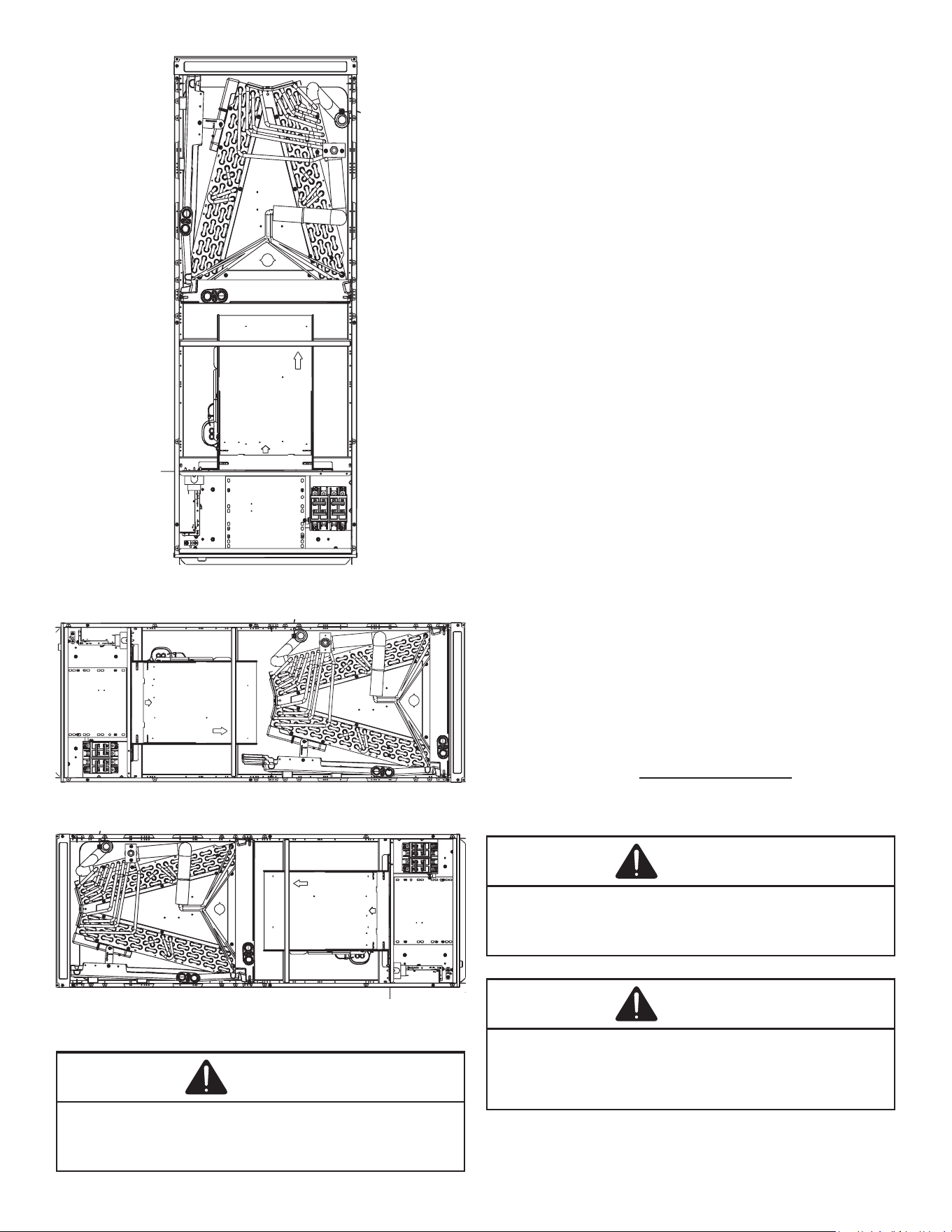
4. Position the unit in the downow position.
5. Using the drain pan to hold the coil assembly, slide the
coil assembly back into the cabinet on the downow
brackets as shown in Figure 8.
6. Reinstall the center support (if removed) using the two
(2) screws removed in Step 5.
7. Reinstall the coil access panels and reinstall blower
access panel removed in Step 1 as shown in Figure 9.
8. Drain Connections for Horizontal Right Installation
a. The bottom right drain connection in side drain pan
is the primary drain for this application and con-
densate drain line must be attached to this drain
connection. The bottom left drain connection is for
the secondary drain line (if used).
b. Remove red plugs from side drain pan before con-
necting condensate drain pipes. Use removed plug
to close drain ports on vertical drain pan.
3. Drain Connections for Downow Installation
a. The bottom left drain connection in the vertical
drain pan is the primary drain for this application
and condensate drain line must be attached to this
drain connection. The bottom right drain connec-
tion is for the secondary drain line (if used).
b. Remove red plugs from vertical drain pan before
connecting condensate drain pipes.
NOTE: If removing only the coil access panel from the unit,
the lter access panel must be removed rst. Failure to do
so will result in panel damage.
UPFLOW
Figure 2
6
DOWNFLOW
Figure 3
HORIZONTAL LEFT
Figure 4
HORIZONTAL RIGHT
Figure 5
7 Refrigerant Lines
WARNING
THIS PRODUCT IS FACTORY-SHIPPED WITH R410A AND DRY
NITROGEN MIXTURE GAS UNDER PRESSURE. USE APPRO-
PRIATE SERVICE TOOLS AND FOLLOW THESE INSTRUCTIONS
TO PREVENT INJURY.
NOTE: Refrigerant tubing must be routed to allow adequate
access for servicing and maintenance of the unit.
Do not install the air handler in a location that violates the
instructions provided with the condenser. If the unit is locat-
ed in an unconditioned area with high ambient temperature
and/or high humidity, the air handler may be subject to nui-
sance sweating of the air handler cabinet. On these installa-
tions, a wrap of 2” berglass insulation with a vapor barrier
is recommended.
7.1 Tubing Size
For the correct tubing size, follow the specication for
the condenser/heat pump.
7.2 Tubing Preparation
All cut ends are to be round, burr free, and clean. Fail-
ure to follow this practice increases the chances for re-
frigerant leaks. The suction line is spun closed and re-
quires tubing cutters to remove the closed end.
NOTE: To prevent possible damage to the tubing joints, do
not handle coil assembly with manifold or owrator tubes.
Always use clean gloves when handling coil assemblies.
7.3 Special Instructions
Units without a factory installed TXV come equipped with
a owrator piston for refrigerant expansion. For most in-
stallations with matching applications, no change to the
owrator piston is required. However, in mix-matched
applications, a owrator piston change may be required.
See the piston kit chart (provided in the literature pack-
et) or consult your local distributor for details regarding
mix-matched owrator piston sizing. If the mix-match
application requires a dierent owrator piston size,
change the owrator piston in the owrator body on the
indoor coil before installing the coil and use the proce-
dure in section 7.4.
NOTE: The use of a heat shield is strongly recommend-
ed when brazing to avoid burning the serial plate or the
nish of the unit. Heat trap or wet rags must be used
to protect heat sensitive components such as service
valves and TXV valves sensing bulb.
WARNING
A QUENCHING CLOTH IS STRONGLY RECOMMENDED TO PRE-
VENT SCORCHING OR MARRING OF THE EQUIPMENT FINISH
WHEN BRAZING CLOSE TO THE PAINTED SURFACES. USE
BRAZING ALLOY OF 5% MINIMUM SILVER CONTENT.
CAUTION
APPLYING TOO MUCH HEAT TO ANY TUBE CAN MELT THE
TUBE. TORCH HEAT REQUIRED TO BRAZE TUBES OF VARI-
OUS SIZES MUST BE PROPORTIONAL TO THE SIZE OF THE
TUBE. SERVICE PERSONNEL MUST USE THE APPROPRIATE
HEAT LEVEL FOR THE SIZE OF THE TUBE BEING BRAZED.
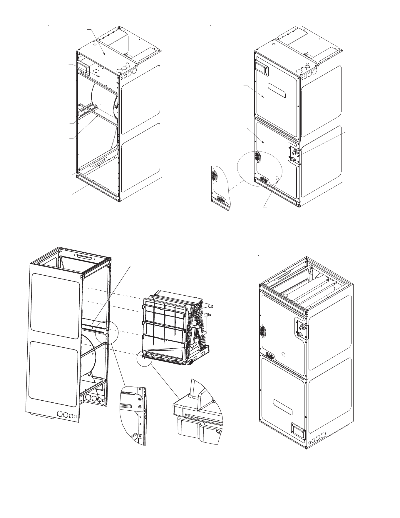
7
EXTERNAL PART TERMINOLOGY
Figure 7
INTERNAL PART TERMINOLOGY
Figure 6
IMPORTANT NOTE:
Ensure coil slides on the rails along the groove provided on the drain pan side
walls. Failure to do so will result in improper condensate drainage.
COIL INSTALLATION FOR DOWNFLOW
Figure 8
Coil slides
on the downflow bracket
Upper Tie Plate
Control
Deck
Downflow
Bracket
Center
Support
Filter
Bracket
Filter
Access
Panel
ACCESS PANEL CONFIGURATION FOR DOWNFLOW
OR HORIZONTAL RIGHT
Figure 9
Blower
Access
Panel
Coil
Access
Panel
UV
Knockout
Tubing
Panel
8
7.4 Tubing Connections for Flowrator Model
1. Loosen the 13/16 nut 1 TURN ONLY to allow high pres-
sure tracer gas to escape. No gas indicates a possible
leak.
2. After the gas has been expelled, remove the nut and
discard the black or brass cap plastic seal.
3. Remove the owrator piston to verify it is the correct
size for the outdoor unit being installed and then re-
place the piston (changing size, if needed). See piston
kit chart in the literature kit for appropriate piston size.
4. Remove the spin closure on the suction line using a
tube cutter and deburr the tube.
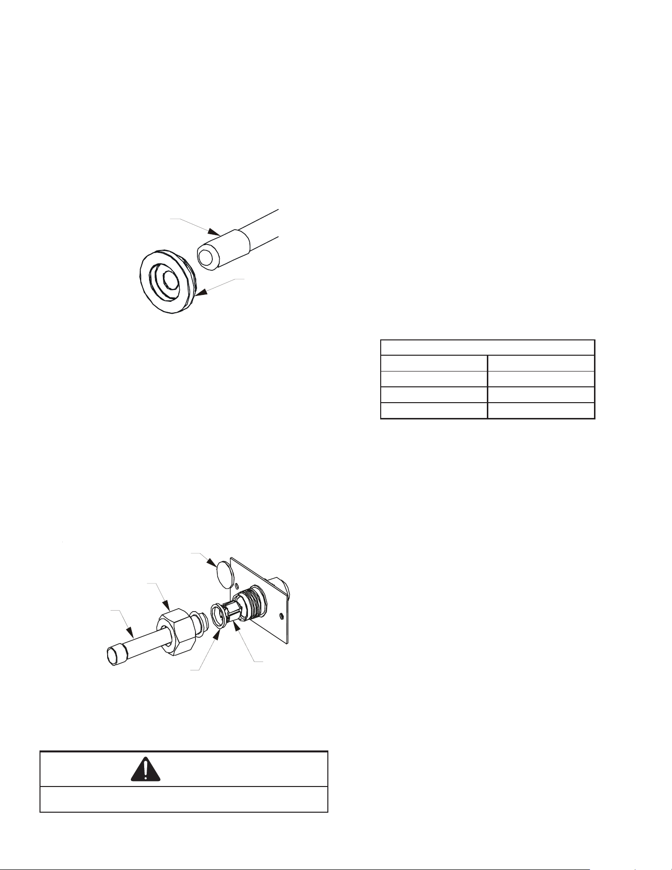
RUBBER
GROMMET
SUCTION LINE
WITH SPIN CLOSURE
SUCTION SPUN END AND GROMMET
Figure 10
5. Insert the suction line into the connection, slide the in-
sulation and the rubber grommet at least 18” away from
the braze joint.
6. Remove the tailpiece clamped to the exterior of the
cabinet or in the literature kit packet and slide the
13/16 nut into place.
7. Braze tailpiece to the line set liquid tube and braze
suction line connection. Quench all brazed joints with
a damp rag upon completion of brazing. Do not allow
water to enter the inside of the tubing.
8. AFTER THE TAILPIECE HAS COOLED, conrm po-
sition of the white Teon® seal and hand tighten the
13/16 nut.
WHITE
TEFLON SEAL
PISTON
TAILPIECE
13/16” NUT
PLASTIC or BRASS CAP
TAILPIECE JOINT
Figure 11
9. Torque the 13/16 nut to 7-25 ft-lbs. or tighten 1/6 turn.
CAUTION
EXCESSIVE TORQUE CAN CAUSE ORIFICES TO STICK. USE THE
PROPER TORQUE SETTINGS WHEN TIGHTENING ORIFICES.
7.5 Tubing Connections for TXV Models
TXV models come with factory installed TXV with the
bulb pre-installed on the vapor tube.
1. Remove refrigerant tubing panel or coil (lower) access
panel.
2. Remove access valve tting cap and depress the valve
stem in access tting to release pressure. No pressure
indicates possible leak.
3. Replace the refrigerant tubing panel.
4. Remove the spin closure on both the liquid and suction
tubes using a tubing cutter.
5. Insert liquid line set into liquid tube expansion and slide
grommet about 18” away from braze joint.
6. Insert suction line set into suction tube expansion and
slide insulation and grommet about 18” away from
braze joint.
7. Braze joints. Quench all brazed joints with water or a
wet rag upon completion of brazing.
7.6 ASPT**14** Models with Non-Adjustable TXV
ASPT air handlers equipped with Parker non-adjustable
TXV should be charged by subcooling only.
ASPT25B14**A SPT47D14**
ASPT29B14**A SPT47C14**
ASPT37B14**A SPT49D14**
ASPT37C14**A SPT59C14**
Models
Table 4
See section 7.7 for detailed information on adjusting the
thermal expansion valve.
7.7 Thermal Expansion Valve System Adjustment
Run the system at Cooling for 10 minutes until refrigerant
pressures stabilize. Use the following guidelines and meth-
ods to check unit operation and ensure that the refrigerant
charge is within limits. Charge the unit on low stage.
1. Purge gauge lines. Connect service gauge manifold to
base-valve service ports.
2. Temporarily install a thermometer on the liquid line at
the liquid line service valve and 4-6” from the compres-
sor on the suction line. Ensure the thermometer makes
adequate contact and is insulated for best possible
readings. Use liquid line temperature to determine sub-
cooling and vapor temperature to determine superheat.
3. Check subcooling and superheat. Systems with TXV
application should have a subcooling of 7 to 9ºF and
superheat of 7 to 9 ºF.
a. If subcooling and superheat are low, adjust TXV to
7 to 9 ºF superheat, then check subcooling.
NOTE: To adjust superheat, turn the valve stem
clockwise to increase and counter clockwise to de-
crease.
b. If subcooling is low and superheat is high, add
charge to raise subcooling to 7 to 9ºF then check
superheat.
c. If subcooling and superheat are high, adjust TXV
valve to 7 to 9 ºF superheat, then check subcooling.
9
SUCTION PRESSURE
PSIG R-22 R-410A
50 26 1
52 28 3
54 29 4
56 31 6
58 32 7
60 34 8
62 35 10
64 37 11
66 38 13
68 40 14
70 41 15
72 42 16
74 44 17
76 45 19
78 46 20
80 48 21
85 50 24
90 53 26
95 56 29
100 59 31
110 64 36
120 69 41
130 73 45
140 78 49
150 83 53
160 86 56
170 90 60
SATURATED SUCTION PRESSURE
TEMPERATURE CHART
SATURATED SUCTION
d. If subcooling is high and superheat is low, adjust
TXV valve to 7 to 9 ºF superheat and remove
charge to lower the subcooling to 7 to 9ºF.
NOTE: Do NOT adjust the charge based on suction pres-
sure unless there is a gross undercharge.
4. Disconnect manifold set, installation is complete.
NOTE: Check the Schrader ports for leaks and tighten valve
cores if necessary. Install caps nger-tight.
SUBCOOL FORMULA =
SAT. LIQUID LINE TEMP. - LIQUID LINE TEMP.
SUPERHEAT FORMULA =
SUCT. LINE TEMP. - SAT. SUCT. TEMP.
NOTE: Expansion valve system in ASPT models are already
tuned for 16 SEER single stage Heat Pump, adjustment of
Expansion valve system is required in case subcool, super-
heat does not match to Section 7.6.3 above or when these
models are installed with any other outdoor models.
LIQUID PRESSURE
PSIG R-22 R-410A
200 101 70
210 105 73
220 108 76
225 110 78
235 113 80
245 116 83
255 119 85
265 121 88
275 124 90
285 127 92
295 130 95
305 133 97
325 137 101
355 144 108
375 148 112
405 155 118
415 157 119
425 n/a 121
435 n/a 123
445 n/a 125
475 n/a 130
500 n/a 134
525 n/a 138
550 n/a 142
575 n/a 145
600 n/a 149
625 n/a 152
SATURATED LIQUID PRESSURE
TEMPERATURE CH ART
SATURATED LIQUID
TEMPERATURE ºF
NOTE: Units matched with indoor coils equipped with
non-adjustable TXV should be charged by subcooling only.
10
8 Condensate Drain Lines
The coil drain pan has a primary and a secondary drain with
3/4” NPT female connections. The connectors required are
3/4” NPT male, either PVC or metal pipe, and should be
hand tightened to a torque of no more than 37 in-lbs. to pre-
vent damage to the drain pan connection. An insertion depth
of approximately 3/8” to 1/2” (3-5 turns) should be expected
at this torque.
1. Ensure drain pan hole is not obstructed.
2. To prevent potential sweating and dripping on to n-
ished space, it may be necessary to insulate the con-
densate drain line located inside the building. Use Ar-
maex® or similar material.
A secondary condensate drain connection has been provid-
ed for areas where the building codes require it. Pitch all
drain lines a minimum of 1/4” per foot to provide free drain-
age. Provide required support to the drain line to prevent
bowing.
If the secondary drain line is required, run the line sepa-
rately from the primary drain and end it where condensate
discharge can be easily seen.
NOTE: Water coming from secondary line means the coil
primary drain is plugged and needs immediate attention.
CAUTION
IF SECONDARY DRAIN IS NOT INSTALLED, THE SECONDARY
ACCESS MUST BE PLUGGED.
Insulate drain lines located inside the building or above a n-
ished living space to prevent sweating. Install a condensate
trap to ensure proper drainage.
NOTE: When units are installed above ceilings, or in other
locations where damage from condensate overow may oc-
cur, it is MANDATORY to install a eld fabricated auxiliary
drain pan under the coil cabinet enclosure.
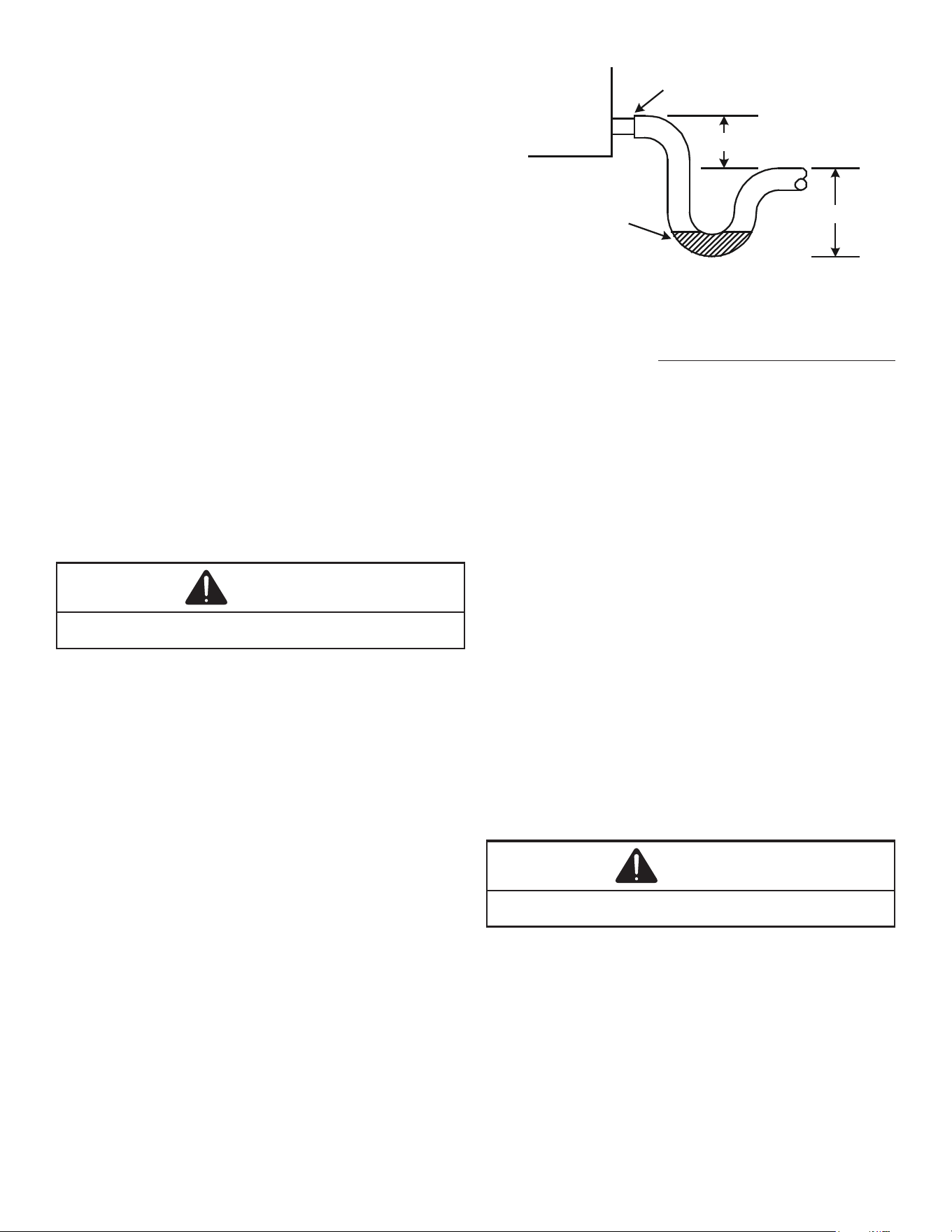
The installation must include a “P” style trap that is located
as close as is practical to the evaporator coil. See Figure 12
for details of a typical condensate line “P” trap.
NOTE: Units operating in high static pressure applications
may require a deeper eld constructed “P” style trap than
is shown in Figure 12 to allow proper drainage and prevent
condensate overow.
Air Handler
2.75" MI
N.
POSITIVE LIQUID
SEAL REQUIRED
AT TRAP
Drain
Connection
2" MIN.
Figure 12
NOTE: Trapped lines are required by many local codes. In
the absence of any prevailing local codes, please refer to the
requirements listed in the Uniform Mechanical Building Code.
A drain trap in a draw-through application prevents air from
being drawn back through the drain line during fan operation
thus preventing condensate from draining, and if connected
to a sewer line to prevent sewer gases from being drawn
into the airstream during blower operation.
Use of a condensate removal pump is permitted when nec-
essary. This condensate pump should have provisions for
shutting o the control voltage should a blocked drain occur.
A trap must be installed between the unit and the conden-
sate pump.
IMPORTANT NOTE: The evaporator coil is fabricated with
oils that may dissolve styrofoam and certain types of plas-
tics. Therefore, a removal pump or oat switch must not con-
tain any of these materials.
Tip: Priming the “P” trap may avoid improper draining at the
initial installation and at the beginning of the cooling season.
9 Ductwork
This air handler is designed for a complete supply and return
ductwork system.
CAUTION
DO NOT OPERATE THIS PRODUCT WITHOUT ALL THE
DUCTWORK ATTACHED.
To ensure correct system performance, the ductwork is to
be sized to accommodate 350-450 CFM per ton of cooling
with the static pressure not to exceed 0.5” in w.c. Refer to
ACCA Manual D, Manual S and Manual RS for information
on duct sizing and application. Flame retardant ductwork
is to be used and sealed to the unit in a manner that will
prevent leakage.
NOTE: A downow application with electric heat must have
an L-shaped sheet metal supply duct without any outlets or
registers located directly below the heater.
11
9.1 Return Ductwork
DO NOT LOCATE THE RETURN DUCTWORK IN AN
AREA THAT CAN INTRODUCE TOXIC, OR OBJEC-
TIONABLE FUMES/ODORS INTO THE DUCTWORK.
The return ductwork is to be connected to the air handler
bottom (upow conguration).
10 Return Air Filters
Each installation must include a return air lter. This ltering
may be performed at the air handler using the factory lter
rails or externally such as a return air lter grille. When us-
ing the factory lter rails, a nominal 16x20x1”, 20x20x1” or
24x20x1” (actual dimension must be less than 23-½”x20”)
lter can be installed on a B, C and D cabinet respectively
(the cabinet size is the seventh letter of the model number).
11 Electric Heat
Refer to the installation manual provided with the electric
heat kit for the correct installation procedure. All electric
heat must be eld installed. If installing this option, the ONLY
heat kits that are permitted to be used are the HKS series.
Refer to the air handler unit’s Serial and Rating plate or the
HKS specication sheets to determine the heat kits compat-
ible with a given air handler. No other accessory heat kit be-
sides the HKS series may be installed in these air handlers.
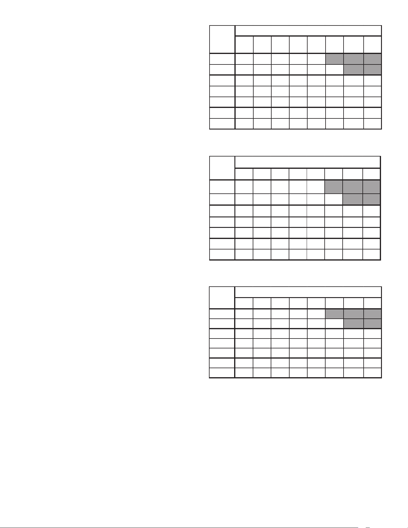
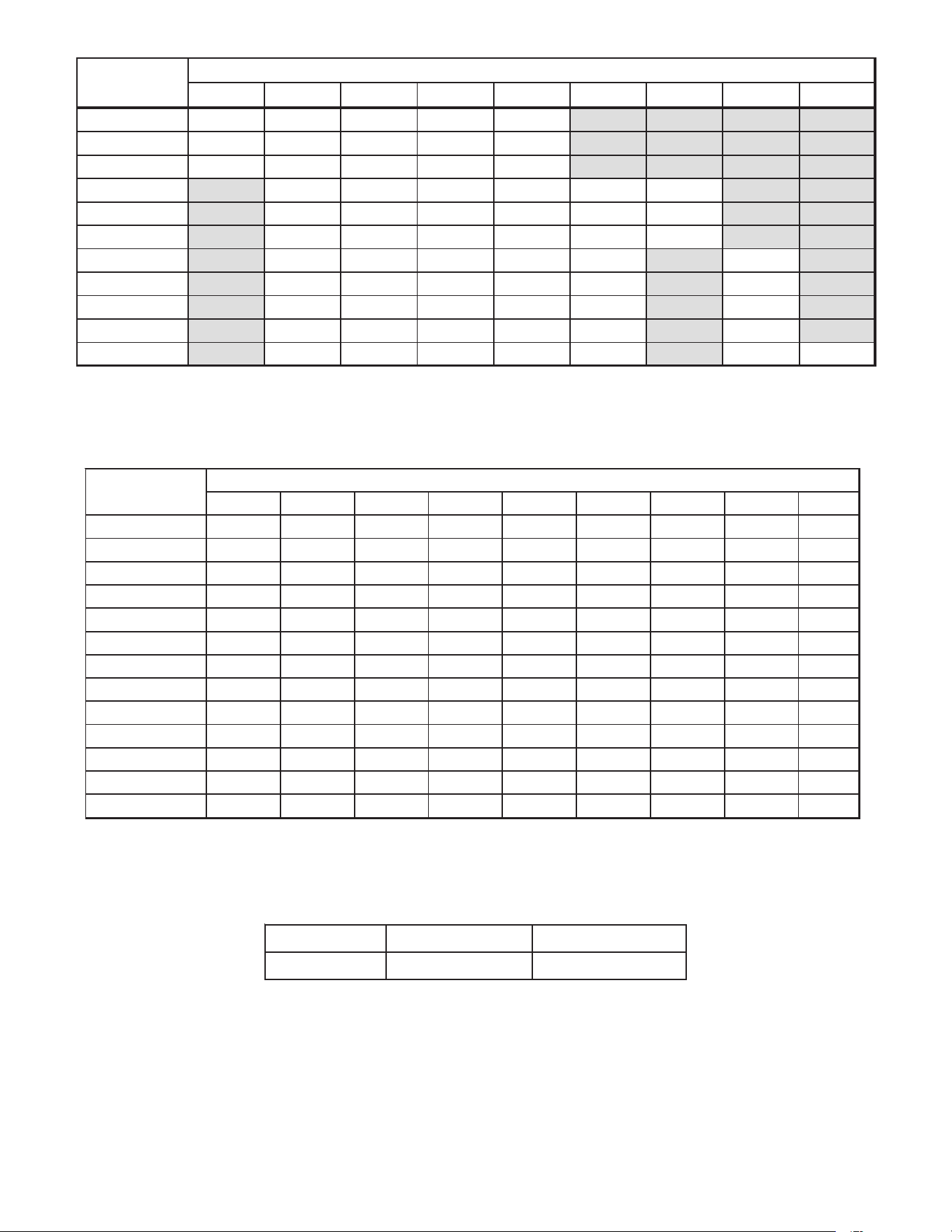
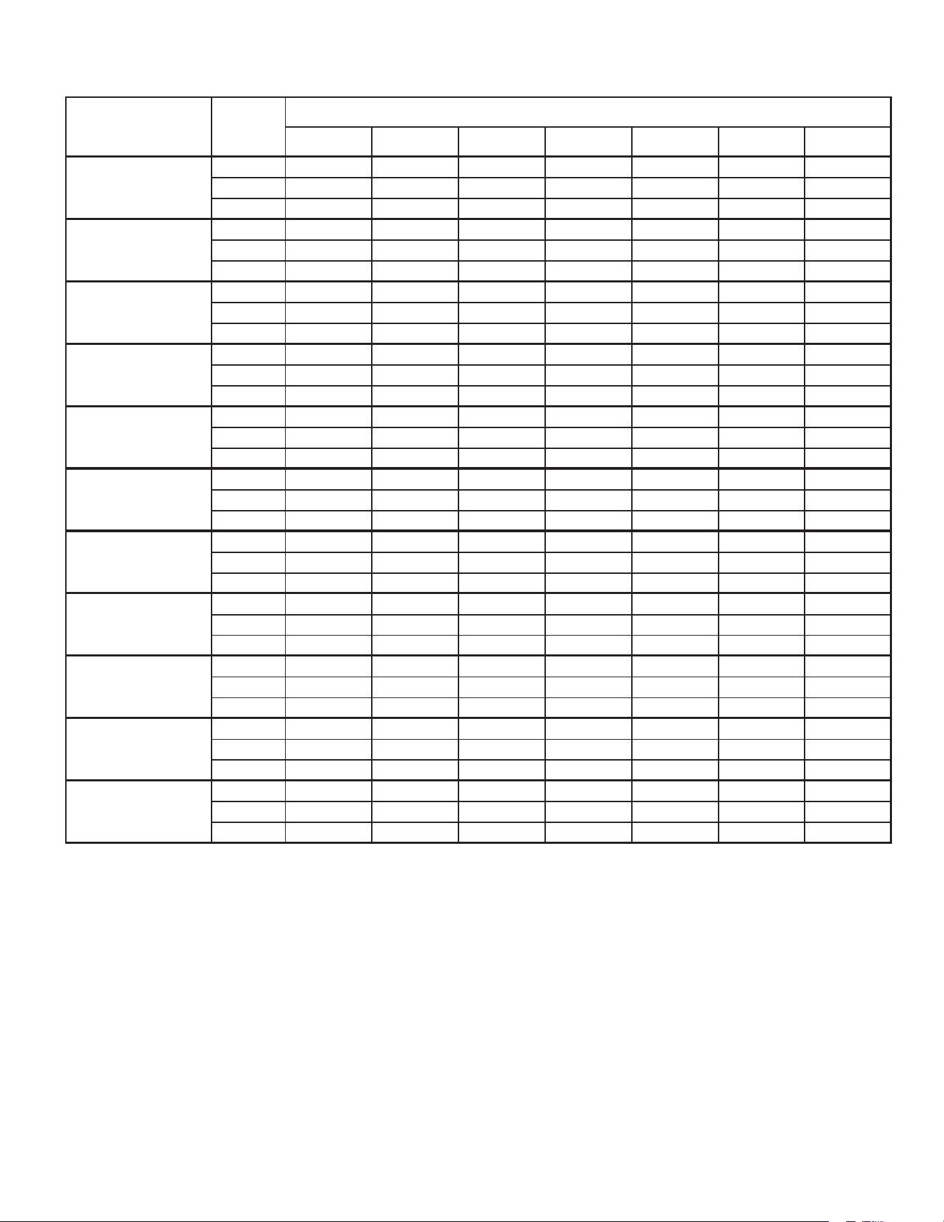
The heating mode temperature rise is dependent upon the
system airow, the supply voltage, and the heat kit size (kW)
selected. Use data provided in Tables 5, 6, AND 7 to deter-
mine the temperature rise (°F).
NOTE: For installations not indicated above the following
formula is to be used:
TR = (kW x 3412) x (Voltage Correction) / (1.08XCFM)
Where: TR = Temperature Rise
kW = Heater Kit Actual kW
3412 = Btu per kW
VC* = .96 (230 Supply Volts)
= .92 (220 Supply Volts)
= .87 (208 Supply Volts)
1.08 = Constant
CFM = Measured Airow
*VC (Voltage Correction)
NOTE: The Temperature Rise Tables can also be used to
estimate the air handler airow delivery. When using these
tables for this purpose set the room thermostat to maximum
heat and allow the system to reach steady state conditions.
Insert two thermometers, one in the return air and one in the
supply air. The temperature rise is the supply air tempera-
ture minus the room air temperature. Using the temperature
rise calculated, CFM can be estimated from the TR formula
above. See Service Manual for more information.
3568 10 15 19/20 25
800 12 19 23 31 37
1000 9 15 19 25 30 44
1200 8 12 15 21 25 37 49 62
1400 7 11 13 18 21 32 42 53
1600 6 9 12 15 19 28 37 46
1800 5 8 10 14 16 25 33 41
2000 579 12 15 22 30 37
CFM
HEAT KIT NOMINAL kW
230/1/60 SUPPLY VOLTAGE - TEMP. RISE °F
Table 5
3568 10 15 19/20 25
800 11 18 22 30 35
1000 9 14 18 24 28 42
1200 7 12 15 20 24 35 47 59
1400 6 10 13 17 20 30 40 51
1600 6 9 11 15 18 27 35 44
1800 5 8 10 13 16 24 31 39
2000 479 12 14 21 28 35
CFM
HEAT KIT NOMINAL kW
220/1/60 SUPPLY VOLTAGE - TEMP. RISE °F
Table 6
3568 10 15 19/20 25
800 10 17 21 28 33
1000 8 13 17 22 27 40
1200 7 11 14 19 22 33 45 56
1400 6 10 12 16 19 29 38 48
1600 5 8 10 14 17 25 33 42
1800 579 12 1 5 22 30 37
2000 478 11 1 3 20 27 33
CFM
HEAT KIT NOMINAL kW
208/1/60 SUPPLY VOLTAGE - TEMP. RISE °F
Table 7
12
12 Electrical and Control Wiring
IMPORTANT: All routing of electrical wiring must be made
through provided electrical knockouts. Do not cut, puncture
or alter the cabinet for electrical wiring.
WARNING
HIGH VOLTAGE
DISCONNECT ALL POWER BEFORE SERVICING
OR INSTALLING THIS UNIT. MULTIPLE POWER
SOURCES MAY BE PRESENT. FAILURE TO DO
SO MAY CAUSE PROPERTY DAMAGE, PERSON-
AL INJURY OR DEATH.
WARNING
HIGH VOLTAGE!
TO AVOID PROPERTY DAMAGE, PERSONAL INJURY OR DEATH
DUE TO ELECTRICAL SHOCK, THIS UNIT MUST HAVE AN UNINTER-
RUPTED, UNBROKEN ELECTRICAL GROUND. THE ELECTRICAL
GROUND CIRCUIT MAY CONSIST OF AN APPROPRIATELY SIZED
ELECTRICAL WIRE CONNECTING THE GROUND LUG IN THE UNIT
CONTROL BOX TO THE BUILDING ELECTRICAL SERVICE PANEL.
OTHER METHODS OF GROUNDING ARE PERMITTED IF PER-
FORMED IN ACCORDANCE WITH THE NATIONAL ELECTRIC CODE
(NEC)/AMERICAN NATIONAL STANDARDS INSTITUTE (ANSI)/NA-
TIONAL FIRE PROTECTION ASSOCIATION (NFPA) 70 AND LOCAL/
STATE CODES. IN CANADA, ELECTRICAL GROUNDING IS TO BE IN
ACCORDANCE WITH THE CANADIAN ELECTRIC CODE (CSA) C22.1.
12.1 Building Electrical Service Inspection
This unit is designed for single-phase electrical supply
only. DO NOT OPERATE ON A THREE-PHASE POW-
ER SUPPLY. Measure the power supply to the unit. The
supply voltage must be measured and be in agreement
with the unit nameplate power requirements and within
the range shown.
12.2 Wire Sizing
Wire size is important to the operation of your equip-
ment. Use the following check list when selecting the
appropriate wire size for your unit.
• Wire used must carry the Minimum Circuit Ampacity
(MCA) listed on the unit’s Series and Rating Plate.
• Refer to the NEC (USA) or CSA (Canada) for wire
sizing. The unit MCA for the air handler and the op-
tional electric heat kit can be found on the unit Series
and Rating Plate.
• Wire must be sized to allow no more than a 2% volt-
age drop from the building breaker/fuse panel to the
unit.
• Wires with dierent insulation temperature rating
have varying ampacities - be sure to check the tem-
perature rating used.
Refer to the latest edition of the National Electric
Code or in Canada the Canadian Electric Code when
determining the correct wire size.
12.3 Maximum Overcurrent Protection (MOP)
Every installation must include an NEC (USA) or CEC
(Canada) approved overcurrent protection device. Also,
check with local or state codes for any special regional
requirements.
Protection can be in the form of fusing or HACR style
circuit breakers. The Series and Rating Plate provides
the maximum overcurrent device permissible.
NOTE: Fuses or circuit breakers are to be sized larger
than the equipment MCA but not to exceed the MOP.
13
3 5 6 8 10 15 19 20 25
ARUF25B14 715 715 715 715 950
ARUF29B14 715 715 715 715 950
ARUF31B14 715 715 715 715 875
ARUF37C14 1170 1170 1170 1170 1345 1345
ARUF43C14 1170 1170 1170 1170 1345 1345
ARUF49C14 1170 1170 1170 1170 1340 1430
ARUF37D14 1170 1170 1170 1170 1345 1345
ARUF43D14 1170 1170 1170 1170 1345 1345
ARUF47D14 1170 1170 1170 1170 1345 1345
ARUF49D14 1240 1240 1240 1240 1520 1520
ARUF61D14 1590 1590 1590 1590 1715 1715 1715
M ODEL
HEATER KIT (KW)
MINIMUM CFM REQUIRED FOR HEATER KITS
Table 8
MINIMUM HEATER KIT AIRFLOW
Table 9
3 5 6 8 10 15 19 20 25
ASPT25B14 715 715 715 715 850
ASPT29B14 715 715 715 715 875 1050
ASPT35B14 715 715 715 715 875 1050
ASPT37B14 715 715 715 715 875 1050
ASPT33C14 715 715 715 715 875 875
ASPT37C14 1170 1170 1170 1170 1345 1345
ASPT39C14 1170 1170 1170 1170 1345 1345
ASPT47C14 1170 1170 1170 1170 1345 1345
ASPT49C14 1170 1170 1170 1170 1345 1345
ASPT59C14 1170 1170 1170 1170 1345 1345
ASPT47D14 1240 1240 1240 1240 1520 1520
ASPT49D14 1590 1590 1590 1590 1715 1715 1715
ASPT61D14 1590 1590 1590 1590 1715 1715 1715
Model
HEATER KIT (KW)
ELECTRICAL VOLTAGE
Table 10
Nominal Input Minimum Voltage Maximum Voltage
208-240 197 253
14
12.4 Electrical Connections – Supply Voltage
CAUTION
FIRE HAZARD!
TO AVOID THE RISK OF PROPERTY DAMAGE, PERSONAL INJU-
RY OR FIRE, USE ONLY COPPER CONDUCTORS.
IMPORTANT NOTE: USE COPPER CONDUCTORS ONLY
FROM DISCONNECT OR ELECTRICAL PANEL TO THE
AIR HANDLER.
Knockouts are provided on the air handler top panel and
sides of the cabinet to allow for the entry of the supply voltage
conductors, as shown in Figure 13. If the knockouts on the
cabinet sides are used for electrical conduit, an adapter ring
must be used in order to meet UL1995 safety requirements.
An NEC or CEC approved strain relief is to be used at this en-
try point. Some codes/municipalities require the supply wire
to be enclosed in conduit. Consult your local codes.
Side of
Cabinet
Top of
Cabinet
KNOCK-OUT FOR ELECTRICAL CONNECTIONS
Figure 13
12.4.1 Air Handler Only (Non-Heat Kit Models)
The building supply connects to the stripped black and
red wires contained in the air handler electrical com-
partment cavity. A ground screw is also contained in this
area. Attach the Supply wires to the air handler conduc-
tors as shown in the unit wiring diagram using appropri-
ately sized solderless connectors or other NEC or CEC
approved means.
12.4.2 Air Handler - Non-Circuit Breaker Heat Kits
A terminal block is provided with the HKS kit to attach
the power supply and air handler connections. Follow
the HKS Installation Manual and wiring diagram for
complete wiring details.
12.4.3 Air Handler With Circuit Breaker Heat Kit
The air handler has soft plastic cover on the upper ac-
cess panel and can be removed to allow the heater kit
circuit breaker to be installed. The circuit breakers have
lugs for power supply connection. See the HKS Installa-
tion Instructions for further details.
12.5 Low Voltage Connections
Several combinations of low voltage schemes are possi-
ble, depending on the presence of a heat kit and wheth-
er the heat kit is single-stage or multi-stage, whether the
outdoor section is an air conditioner or heat pump, and
whether the outdoor section is single-stage or two-stage.
The 24V-control voltage connects the air handler to the
room thermostat and condenser. Low voltage wiring
must be copper conductors. A minimum of 18AWG must
be used for installations up to 100 feet. Low voltage wir-
ing must be connected through the top of the cabinet or
either side. See the “Thermostat Wiring” section of this
manual for typical low voltage wiring connections.
12.5.1 Thermostats
Second-stage heat can be accomplished by a multi-
stage heating thermostat or the addition of an outdoor
thermostat as shown in wiring schematics on page 19.
Follow the thermostat manufacturer’s instructions for in-
stallation.
12.6 Speed Tap Adjustment
ARUF**14** air handlers have multi-speed PSC mo-
tors. The color of the wire coming from the motor to the
“COM” terminal on the control board denes at which
speed the motor will operate. Black wire is high speed,
blue wire is medium speed and red wire is low speed. To
change speeds, remove the wire attached to the “COM”
terminal on the control board, and swap it with the wire
(on terminal “M1” or “M2”) with the color that will give the
desired speed.
15
ASPT**14** air handlers feature energy ecient blower
motors. The motors run at a constant torque with very
low power consumption and are energized by 24 VAC.
Adjust the CFM by changing the 24 VAC leads to the de-
sired speed tap on the terminal block. The ASPT blower
motor speeds are programmed to deliver adequate air-
ow at rated external static pressure and with 60 sec-
ond o time delay. For details, refer to the specication
sheet applicable to your model.
NOTE: In some models, not all speed taps are allowable
for certain electric heat applications. Refer to Table 6 for
minimum speed.
13 Achieving 1.4% Low Leakage Rate
Ensure all the gaskets remain intact on all surfaces as
shipped with the unit. These surfaces are areas between
the upper tie plate and blower access panel, blower access
and coil access panels, and between the coil access and
lter access panels. Ensure upon installation, that the plastic
breaker cover is sitting ush on the blower access panel and
all access panels are ush with each other and the cabinet.
With these requirements satised, the unit achieves less
than 1.4% airow leakage when tested in accordance with
ASHRAE Standard 193.
14 Start-Up Procedure
WARNING
HIGH VOLTAGE
DISCONNECT ALL POWER BEFORE SERVICING
OR INSTALLING THIS UNIT. MULTIPLE POWER
SOURCES MAY BE PRESENT. FAILURE TO DO
SO MAY CAUSE PROPERTY DAMAGE, PERSON-
AL INJURY OR DEATH.
• Prior to start-up, ensure that all electrical wires are
properly sized and all connections are properly tight-
ened.
• All panels must be in place and secured. For Air Tight
application, gasket must be positioned at prescribed
locations to achieve 1.4% leakage.
• Tubing must be leak free.
• Condensate line must be trapped and pitched to al-
low for drainage.
• Low voltage wiring is properly connected.
• Auxiliary drain is installed when necessary and
pitched to allow for drainage.
• Unit is protected from vehicular or other physical
damage.
• Return air is not obtained from, nor are there any re-
turn air duct joints that are unsealed in, areas where
there may be objectionable odors, ammable vapors
or products of combustion such as carbon monox-
ide (CO), which may cause serious personal injury
or death.
15 Regular Maintenance
The only item required to be maintained on a regular basis
by the user is the circulating air lter(s). Filter should be
cleaned or replaced regularly, typically once per month. A
certied service technician must perform all other services.
IMPORTANT NOTE: If thumb screws are used to access
the lter, ensure the washer installed on the screw behind
the access panel remains in place after re-installation.
16
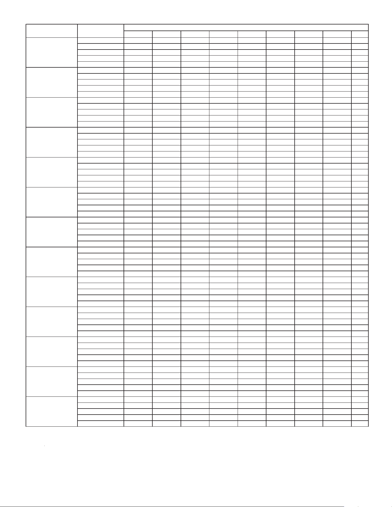
16 Airow Data
AIRFLOW DATA (CFM) - Table 11
0.1 0.2 0.3 0.4 0.5 0.6 0.7
LOW 650 620 595 540 490 420 275
M ED 885 865 825 815 750 690 560
HIGH 1255 1225 1130 1090 965 925 800
LOW 650 620 595 540 490 420 275
M ED 885 865 825 815 750 690 560
HIGH 1255 1225 1130 1090 965 925 800
LOW 660 625 595 560 500 430 330
M ED 930 905 865 820 765 700 590
HIGH 1235 1185 1130 1060 990 910 825
LOW 1120 1085 1040 1000 940 875 800
M ED 1425 1385 1345 1285 1220 1145 1060
HIGH 1625 1575 1520 1460 1375 1295 1200
LOW 1120 1085 1040 1000 940 875 800
M ED 1425 1385 1345 1285 1220 1145 1060
HI
GH 1625 1575 1520 1460 1375 1295 1200
LOW 1295 1255 1225 1175 1120 1055 970
M ED 1535 1485 1420 1370 1295 1215 1130
HIGH 1755 1680 1590 1515 1425 1340 1250
LOW 1155 1115 1070 1015 955 895 840
M ED 1505 1470 1430 1375 1300 1210 1105
HIGH 1785 1735 1680 1625 1555 1440 1330
LOW 1410 1360 1290 1210 1120 1010 920
M ED 1610 1540 1470 1390 1300 1190 1060
HIGH 1900 1830 1740 1645 1540 1420 1280
LOW 1420 1370 1310 1240 1125 1045 960
M ED 1625 1585 1515 1435 1350 1235 1095
HIGH 1930 1890 1820 1735 1635 1505 1355
LOW 1410 1360 1290 1210 1120 1010
920
M ED 1610 1540 1470 1390 1300 1190 1060
HIGH 1900 1830 1740 1645 1540 1420 1280
LOW 1530 1500 1460 1405 1350 1280 1155
M ED 1950 1885 1830 1785 1745 1670 1595
HIGH 2235 2170 2100 2030 1965 1915 1825
Notes
ARUF47D14
Model
Blower
Speed
Static Pressure (in w.c) Airflow (CFM)
ARUF25B14
ARUF29B14
ARUF31B14
ARUF49D14
ARUF61D14
1. Airflow data indicated is at 230V without air filter in place.
2. The chart is for information only. For satisfactory operation, external static pr
essure must not exceed value shown on
3. Use the CFM adjustment factors of 0.98 for horizontal left and 0.96 for horizontal right & downflow orientations
ARUF37C14
ARUF43C14
ARUF49C14
ARUF37D14
ARUF43D14
17
ASPT AIRFLOW DATA (CFM) - Table 12
Notes
3. Use the CFM ad
j
ustment factors of 0.98 for horizontal le� and 0.96 for horizontal ri
g
ht & downflow ori enta� ons.
1. Ai rfl ow data indicated is at 230V without air filter i n
p
lace.
2. The chart is for informa� on onl
y
. For sa� sfactor
y
o
p
era� on
,
external sta� c
p
ressure must not exceed value shown on ra� n
g p
late. The shaded area
0.1 0 . 2 0.3 0 . 4 0 . 5 0 . 6 0 . 7 0 . 8 0 . 9
0820430140940155450855850461T
0945655955460760075275670082T
0855260760070470670085080483T
5270670085180585880290595894T
0511042107215031533157310041044157415T
0625030835545050355650955951T
5445155855265665075475770972T
0355955465965370770970285683T
02707759704808852955908951014T
0221582151310531583101410341564150515T
0360860370875975285485485781T
0675975480885095195295495892T
068509
049069089589099520107013T
5301090100115111511153110711502154214T
0401080158015311551109110321572101315T
09653759703857801954958952011T
52807851905959952015601501105112T
52907901010501580102110611002104213T
5411081151210521092102315531004152414T
5021052158210231553109315141554109415T
5120725330140840455165865681T
0940550060660275870280885392T
0170675975585095590001050101113T
0101550159015311081102210621013106
314T
0621592103310731593153415741515106515T
5660175570085280685985390891T
02854808803956900015401570152112T
02956950015401580102115511091153213T
0911032157215131553109315241054158414T
0821023156310931042108410151535156515T
5120725330140840455165865681T
0940550060660275870280885392T
0170675975585095590001050101113T
0101550159015311081102210621013106314T
0621592103310731593153415741515106515T
065516576537087048
5585985591T
5070775180785295695001050100112T
038588049099530157010211061150213T
5901041109115321572102315631014154414T
0811032157210231063100415341084152515T
099520156015111061100210421082152311T
5511591154210821513155310831024156412T
0121052109210331553159310341074101513T
5921563109315241064109410351565100614T
5521004109415251555109515261066109615T
0601001104110811512155215921033107311T
01210031533107315041
03415641005153512T
5021033104410151545157515161546108613T
5021033152415151506109610871558150914T
5021023102415051506100715771558104915T
026086037587038598059510155011T
587048009069510107010111561101212T
01908905010011541150210521092153313T
0321592105315041554159410351085152614T
5231093153410941045108515261076102715T
039510103210021562102310831534158411T
5301551153215131073103410841525107512T
5811082106310341
574155510751006108613T
0931564101510951526107615171567100814T
5681039107910002040258020212061251225T
5401501108110621533109310441594154511T
5721033108315441505155515061556150712T
5441005155515161566101710671508105813T
5571008154810981539108910202550259024T
5491099103025702021206125912502206225T
A S P T 61D 14A
A
A S P T 37B 14A A
A S P T 37C 14A A
A S P T 47C 14A A
A S P T 59C 14A A
A S P T 47D 14A A
A S P T 49D 14A A
A S P T 39C 14A A
A S P T 49C 14A A
A S P T 33C 14A A
A S P T 35B 14A A
M o d e l B l o w e r S
p eed
S t a � c P re s s u re ( in w . c . ) A irfl o w ( C F M )
A S P T 25B 14A A
A S P T 29B 14A A

18
17 Air Handler Low Voltage Connections
The following composite wiring diagrams detail various con-
gurations in which the air handlers can be used. Examples
include single-stage cooling and heat pump with single or
two-stage electric heating. All these congurations can be
applied with convenient connections to outdoor thermostat
applications.
The following sections are detailed:
• Single-Stage Cooling
• Heat Pump
Each diagram details the connections between room ther-
mostat and the air handlers, and the connections between
the air handlers and the Condensing Unit (or Heat Pump)
with optional connections to Outdoor Thermostats. For each
conguration, refer to the explanation of the proper jumper(s)
to remove for the corresponding blower speed that will result
in the programmed xed speed ECM motor.
IMPORTANT: When matching the ASPT air handlers to
a single speed cooling or heat pump unit, remember to
connect “Y” from the thermostat to the “Y2” on the low
voltage terminal board.
Any equivalent thermostat can be used in place of the man-
ufacturer’s thermostat part number.
19
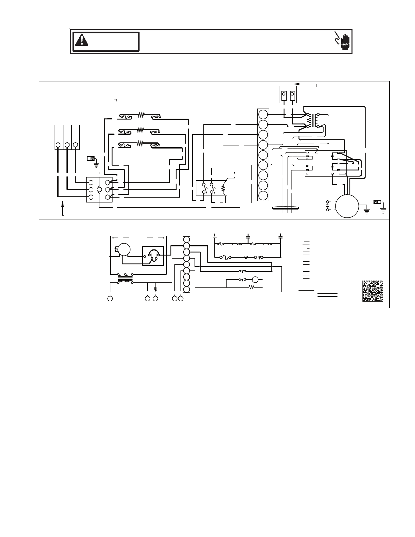
18 Wiring Diagrams
HIGH VOLTAGE!
DISCONNECT ALL POWER BEFORE SERVICING.
MULTIPLE POWER SOURCES MAY BE PRESENT. FAILURE TO DO SO
MAY CAUSE PROPERTY DAMAGE, PERSONAL INJURY OR DEATH.
WARNING
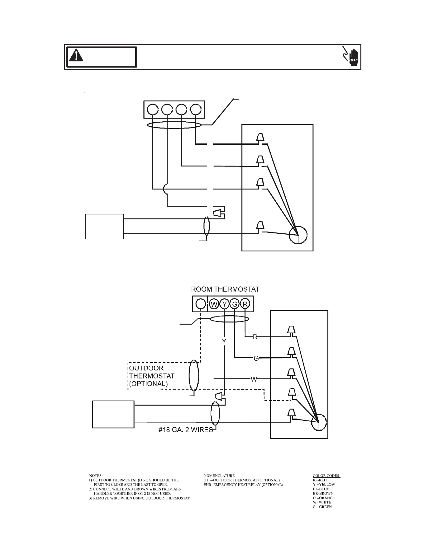
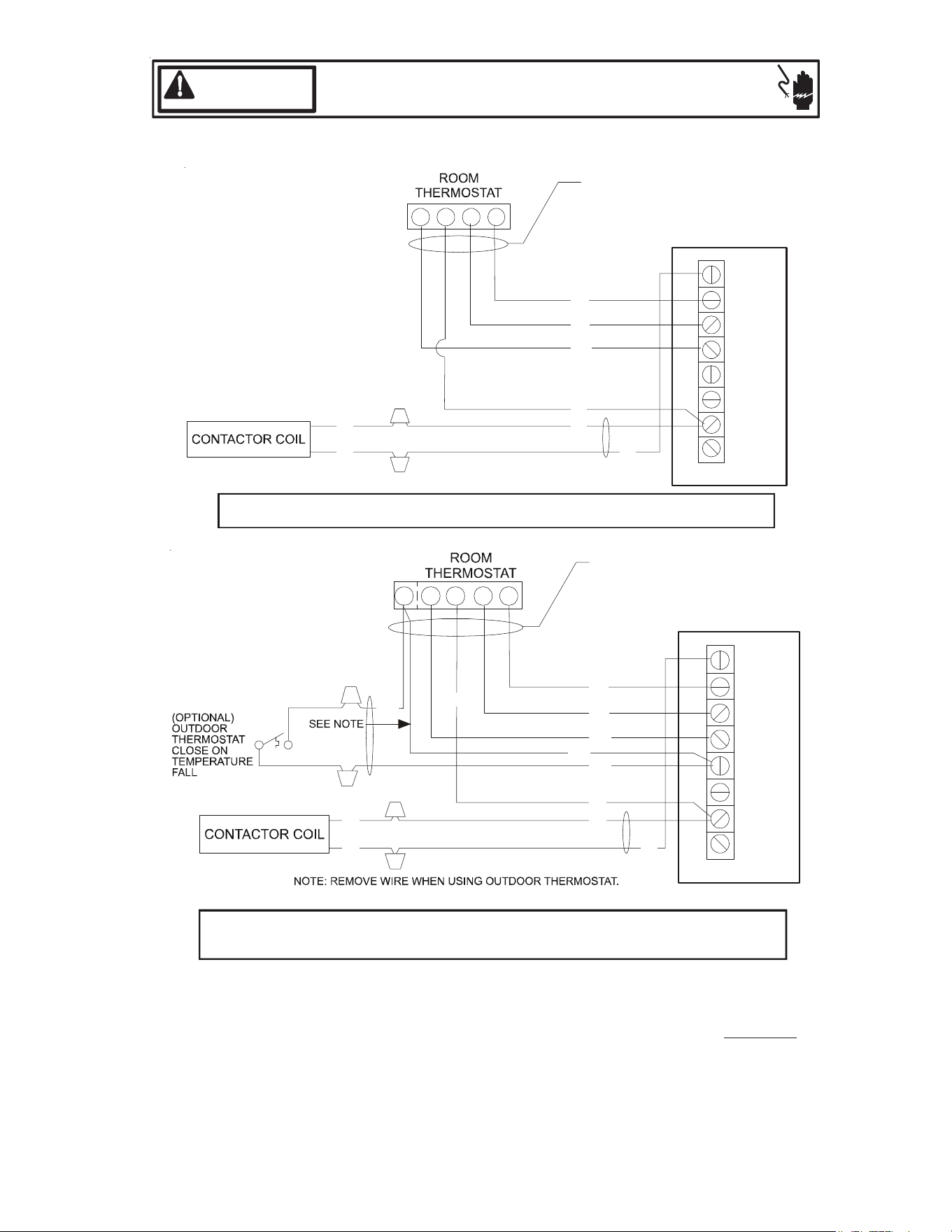
Low Voltage Wiring for ARUF Air Handlers
ROOM THERMOSTAT
W Y
G R
#18 GA. 4 WIRES WITH
COOLING 3 WIRES WITHOUT
R
G
W
Y
TO CONDENSING
UNIT 24V. CONNECTIONS
#18 GA. 2 WIRES
BLUE
WHITE
GREEN
RED
CONTACTOR
COIL
ARUF UNIT
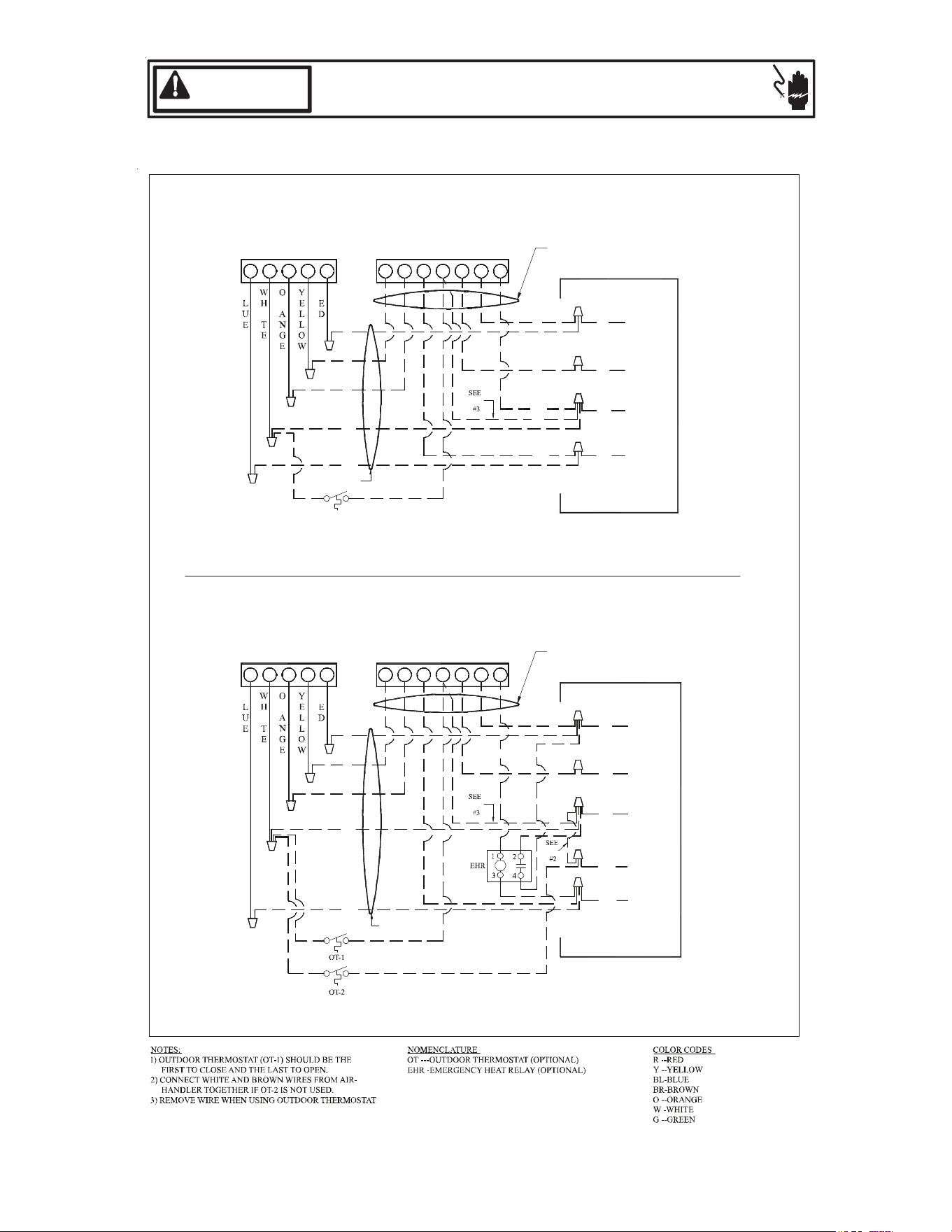
Low Voltage Wiring Diagram for Cooling Unit with optional heat kit 10KW and below
W2
GREEN
RED
WHITE
BLUE
BROWN
#18 GA. 4 WIRE WITH
COOLING 3 WIRE WITHOUT
CONDENSING
UNIT 24V. CONNECTIONS
#18 GA. 2 WIRES
CONTACTOR
COIL
ARUF UNIT
Low Voltage Wiring Diagram for Cooling Unit with optional heat kit 15KW and above
Wiring is subject to change. Always refer to the wiring diagram on the unit for the most up-to-date wiring.
20
HIGH VOLTAGE!
DISCONNECT ALL POWER BEFORE SERVICING.
MULTIPLE POWER SOURCES MAY BE PRESENT. FAILURE TO DO SO
MAY CAUSE PROPERTY DAMAGE, PERSONAL INJURY OR DEATH.
WARNING
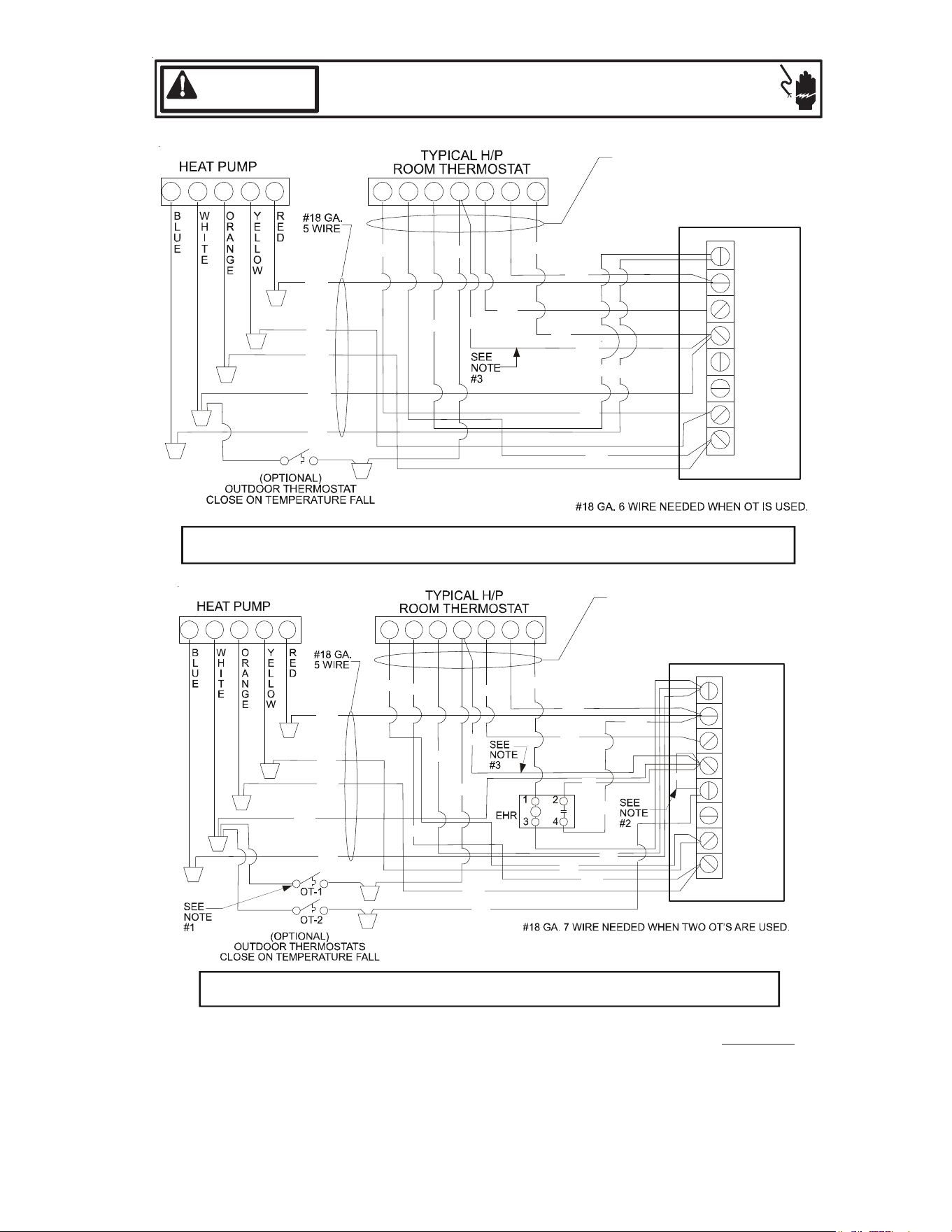
Low Voltage Wiring for ARUF Air Handlers
C
W2
O Y R
YOC G R E
W2
TYPICAL H/P
ROOM THERMOSTAT
HEAT PUMP
ARUF
10 KW & BELOW
(OPTIONAL)
OUTDOOR THERMOSTAT
CLOSE ON TEMPERATURE FALL
RED
GREEN
WHITE
BLUE
AR UNIT
R
Y
O
W
BL
#18 GA. 5 WIRE
#18 GA. 7 WIRE
NOTE
R
G
BR
W
BL
R
R
I
B
#18 GA. 6 WIRE NEEDED WHEN OT IS USED
R
#18 GA. 7 WIRE NEEDED WHEN TWO OT'S ARE USED
#18 GA. 5 WIRE
BL
O
W
Y
BL
NOTE
W
G
BLUE
WHITE
GREEN
TYPICAL H/P
ROOM THERMOSTAT
ARUF
ABOVE 10 KW
HEAT PUMP
B
I
C
W2
R
YO R
R
Y CO
W2
#18 GA. 7 WIRE
RG E
R
AR UNIT
RED
BROWN
NOTE
(OPTIONAL)
OUTDOOR THERMOSTAT
CLOSE ON TEMPERATURE FALL
BR
R
G
BL
W
G
R
BL
BR
Wiring is subject to change. Always refer to the wiring diagram on the unit for the most up-to-date wiring.
21
HIGH VOLTAGE!
DISCONNECT ALL POWER BEFORE SERVICING.
MULTIPLE POWER SOURCES MAY BE PRESENT. FAILURE TO DO SO
MAY CAUSE PROPERTY DAMAGE, PERSONAL INJURY OR DEATH.
WARNING
NOTES:
1) OUTDOOR THERMOSTAT (OT-1) SHOULD BE THE FIRST
TO CLOSE AND THE LAST TO OPEN.
2) JUMPER W1 AND W2 TOGETHER IF OT-2 IS NOT USED.
3) REMOVE WIRE WHEN USING OUTDOOR THERMOSTAT.
NOMENCLATURE:
OT - OUTDOOR THERMOSTAT (OPTIONAL)
EHR - EMERGENCY HEAT RELAY (OPTIONAL)
COLOR CODES
RD - RED
YL - YELLOW
BL - BLUE
BR - BROWN
OR - ORANGE
WH - WHITE
COOLING UNIT WITH OPTIONAL HEAT KITS OF 10 kW AND BELOW
G R
C
W1
YW
W2
Y2
Y1
O
G
R
TB
YL
BL
TO CONDENSING UNIT
24V CONNECTION
BL
YL
YL
WH
GR
RD
#18 GA. 4 WIRES WITH COOLING
3 WIRES WITHOUT
AIR HANDLER
Y GW
W2
R
COOLING UNIT WITH OPTIONAL HEAT KITS OF 15 kW AND ABOVE
AND ROOM THERMOSTAT WITH TWO STAGES OF HEAT
C
W1
W2
Y2
Y1
O
G
R
TB
YL
BL
CONDENSING UNIT
24V CONNECTION
BL
YL
GR
RD
#18 GA. 5 WIRES WITH COOLING
4 WIRES WITHOUT
WH
YL
BR
BR
BR
YL
AIR HANDLER
Wiring is subject to change. Always refer to the wiring diagram on the unit for the most up-to-date wiring.
22
HIGH VOLTAGE!
DISCONNECT ALL POWER BEFORE SERVICING.
MULTIPLE POWER SOURCES MAY BE PRESENT. FAILURE TO DO SO
MAY CAUSE PROPERTY DAMAGE, PERSONAL INJURY OR DEATH.
WARNING
NOTES:
1) OUTDOOR THERMOSTAT (OT-1) SHOULD BE THE FIRST
TO CLOSE AND THE LAST TO OPEN.
2) JUMPER W1 AND W2 TOGETHER IF OT-2 IS NOT USED.
3) REMOVE WIRE WHEN USING OUTDOOR THERMOSTAT.
NOMENCLATURE:
OT - OUTDOOR THERMOSTAT (OPTIONAL)
EHR - EMERGENCY HEAT RELAY (OPTIONAL)
COLOR CODES
RD - RED
YL - YELLOW
BL - BLUE
BR - BROWN
OR - ORANGE
WH - WHITE
GC R
HEAT PUMP UNIT WITH OPTIONAL HEAT KITS OF 10 kW AND BELOW
C
W1
W2
Y2
Y1
O
G
R
TB
#18 GA. 7 WIRE
O
YC
W2
R Y O
W2
E
RD
BR
GR
BR
BL
WH
OR
YL
YL
YL
YL
RD
BL
WH
WH
OR
BL
BL
WH
AIR HANDLER
GC R
HEAT PUMP UNIT WITH OPTIONAL HEAT KITS OF 15 kW AND ABOVE
C
W1
W2
Y2
Y1
O
G
R
TB
#18 GA. 7 WIRE
O
YC
W2
R Y O
W2
E
RD
GR
BL
OR
YL
YL
BL
OR
WH
BR
WH
BL
WH
WH
RD
BR
RD
WH
GR
YL
OR
OR
RD
OR
AIR HANDLER
Wiring is subject to change. Always refer to the wiring diagram on the unit for the most up-to-date wiring.
23
HIGH VOLTAGE!
DISCONNECT ALL POWER BEFORE SERVICING.
MULTIPLE POWER SOURCES MAY BE PRESENT. FAILURE TO DO SO
MAY CAUSE PROPERTY DAMAGE, PERSONAL INJURY OR DEATH.
WARNING
120/240VA
C
TSTA
T
OPTIONAL
SPEEDU
P
24 VAC
SYSTEM
TRANSFORME
R
C
SPEEDU
P
XFM
R
-
C
XFM
R
-
R
R
B13707-35
WIRING DIAGRA
M
M1
PARK TERMINA
L
K1
K1
FOR USE WITH
NEUTRA
L
G
HEAT KI
T
MOTO
R
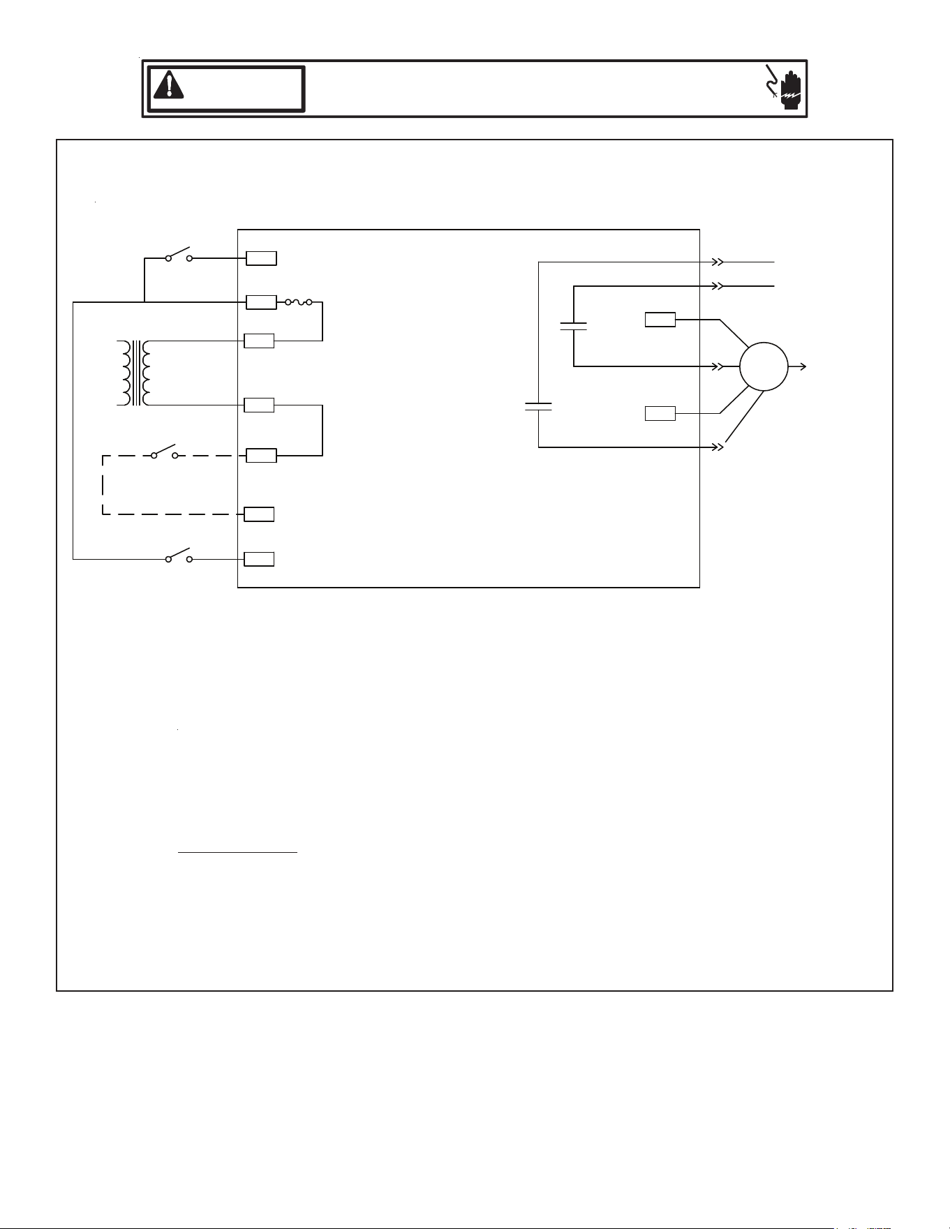
The Electronic Blower Time Delay Relay provides power to the blower motor with a delay of 7
seconds after 24VAC is applied to “G”. After 24VAC is removed from “G”, the blower motor
output is de-energized after a delay of 65 seconds.
Normal Time Delays 60Hz 50Hz
Turn On Delay 7.0 SEC.±1% 8.4 SEC. .±1%
Turn Off Delay 65.0 SEC.±1% 78.0 SEC. .±1%
Field test mode: Shorting the “speedup” quick connect to “C” decrease times as follows:
Speedup Times 60Hz 50Hz
Turn On Delay 3.0 SEC.±1% 3.6 SEC. .±1%
Turn Off Delay 5.0 SEC.±1% 6.0 SEC. .±1%
Field test mode is cancelled when the “speedup” quick connect to “C” short is removed.
ELECTRONIC BLOWER TIME DELAY RELAY
Wiring is subject to change. Always refer to the wiring diagram on the unit for the most up-to-date wiring.
L1-240VAC
TST
AT
OPTIONAL
SPEED UP
24 VAC
C
SPEEDUP
XFMR
XFMR
R
M1
PARK TERMINAL
K1
K2
MOTOR
L2-240VAC
G
M2
PARK TERMINAL
F1
SYSTEM
WIRING DIAGRAM
SYSTEM
TRANSFORMER
TST
AT
W
R
C
L1-240VAC
24
HIGH VOLTAGE!
DISCONNECT ALL POWER BEFORE SERVICING.
MULTIPLE POWER SOURCES MAY BE PRESENT. FAILURE TO DO SO
MAY CAUSE PROPERTY DAMAGE, PERSONAL INJURY OR DEATH.
WARNING
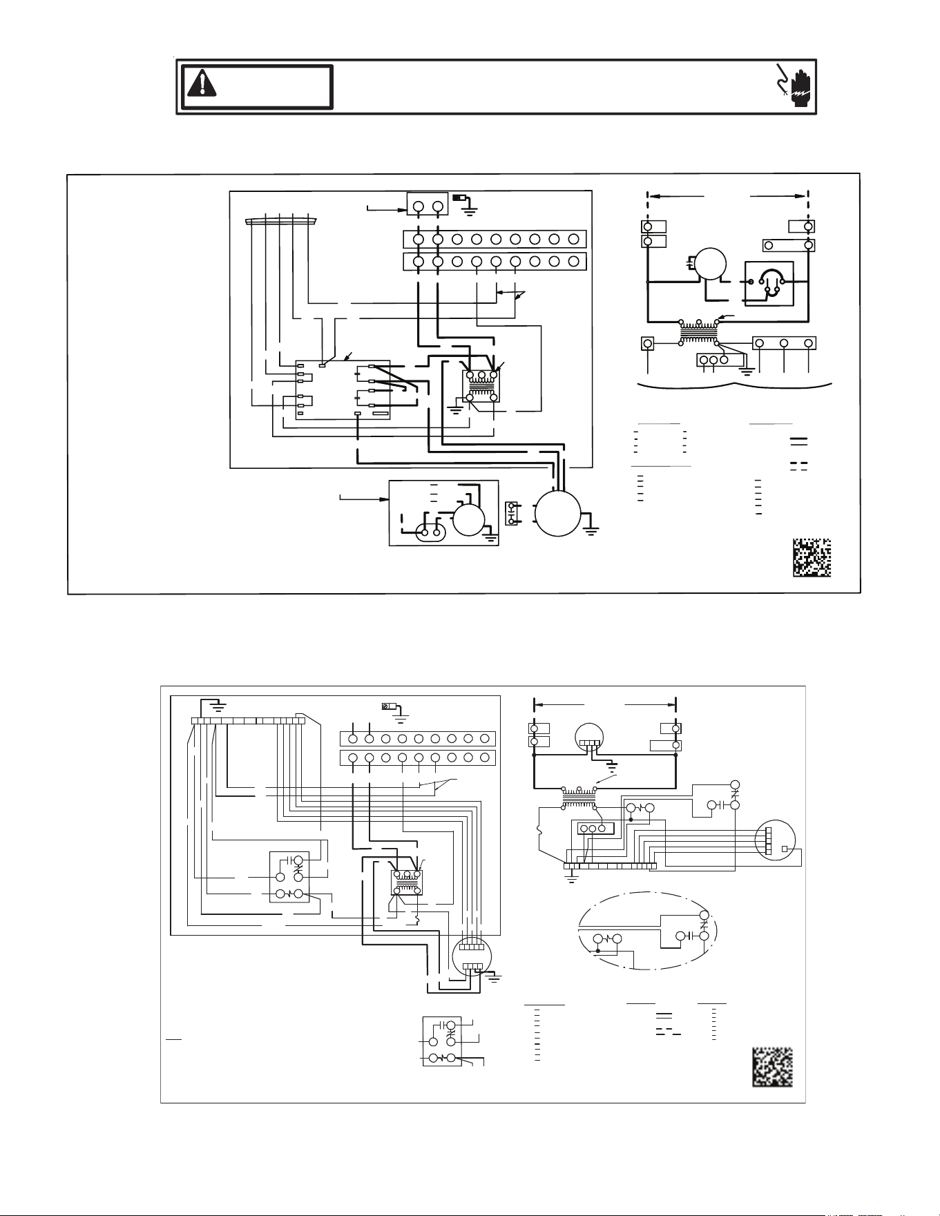
ASPT**14**
ARUF**14**
COPPER POW ER SUPPLY
(USE RATING PLATE)
USE MIN. 75° C F IELD W IRE
0140A00630-A
PLM
PLF
TR
FACTOR Y WIRING
FIELD W IRING
NOTE
S:
1. RED WIR ES TO BE ON TRA NSFORMER TER MINAL "3" FOR 240 V OLTS AND ON
TERMINAL "2" FOR 208 V OLTS.
2. SEE COMPLETE WIRING DIAGRA MS IN INST ALLA TION INSTRUCTIONS FOR
PRO PER LOW VOLTA GE WIRING CONNEC TIONS.
3. "CON FIR M SPEED T AP SELECTION IS APPROP RIATE FOR APPLICATION . IF
SPEED TAP NEEDS TO BE CHAN GED, CONNECT PURPLE W IRE FROM TERMINA L7
OF CR ( TERMINAL 4 OF ALTERN ATE) R ELAY TO A PPROP RIATE TAP A T TB”
4. BROWN AND WHITE WIRES ARE U SED FO R HEAT KI TS ON LY.
5. FUS E: 3A, 250V, 3AG ATO S TYLE FUSE. OP TION AL FU SE 3 AM P CARTRIDGE.
6. LOW VOLTA GE FIELD WIRING T O BE N.E.C CLASS 2 W IRES.
RELAY
EVAPOR ATOR M OTOR
TERM INAL BOARD
R
EM
TB
BK
RD
BL
YL
BLUE
BLAC K
RED
YELLOW
COMPON ENT COD E
BROWN
PURPLE
GREEN
PU
BR
GR
FEMALE PLUG CONNECTOR
MALE PLUG CONNECTOR
TRANSFORMER
HIGH V OLTAGE
LOW VOLTA GE
HIGH VOLTA GE
LOW VOLTA GE
PLF
2
COLOR CODE
TR
6 5 PLM
4
4
24V
5
1
2 3
EM
W
IRING COD E
208/240 VOLTS
1
1
PLF
PLM
L1
PLM
2
L2
IF REP LACEMENT OF THE ORI GINAL W IRES
SUPPLIED WITH THIS A SSEMBLY IS NEC ESSARY,
USE W IRE THAT CONFOR MS TO THE NATIONAL
ELECTRIC CO DE.
FL
FUSE LINK
TL
THERMAL LIM IT
CR
CONTRO L RELAY
WHITEWH
L G
N
W2R W1C G 4Y1 OY2 1DH 3 25
A
B
1
C
EM
2
4
3
5
4
7
CR
1
SEE NOT E 1
U
S
E
C
O
P
P
E
R
W
I
R
E
E
Q
U
IP
M
E
N
T
G
R
O
U
N
D
B
L
E
M
Y
L
B
L
5
B
K
C
B
K
P
L
F
B
K
1
R
D
2
3
2
4
0
2
4
V
4
1
2
3
T
R
R
D
B
L
B
R
4
5
W
H
6
7
8
9
P
L
M
G
R
D
1
2
3
4
5
6
7
8
9
A
B
1
7
4
C
R
S
E
E
N
O
T
E
S
2
&
6
2
1
4
3
5
N
C
G
L
R
D
P
U
B
L
B
R
W
H
B
L
R
D
G
R
R
D
o
r
B
K
B
L
R
D
B
K
R
D
W
2
R
W
1
C
G
4
Y
1
O
Y
2
1
D
H
3
2
5
R
D
o
r
B
K
P
U
B
R
W
H
O
R
W
H
W
H
B
L
G
R
R
D
o
r
B
K
B
L
L
2
L
1
SEE
NOTE 1
SEE
NOTE 4
1
3
5
4
2
ALTERNATE CONTR OL RELAY
B
L
P
U
R
D
G
R
W
H
B
L
1
3
2
4
CR
5
ALTERN ATE H EAT RELAY
GRND
GROUND
S
E
E
N
O
T
E
S
2
&
6
F
U
S
E
F
U
S
E
TB
TB
USE COPPER WIRE
SPEEDUP
COPPER POWER SUPPLY
(SEE RATING PLATE)
EQUIPMENT GROUND
BL
BL
SEE
NOTE 3
BK
M1
BR
BR
RC
EM
RD
BL
BK
RD
PU
EBTDR
SR
BL
G
RD
XFMR-R
XFMR-C
C
R
RD
GR
SEE NOTES 2 & 6
BL
RD GR
WH BR
5
NO
RY1
RY2
PU
RD
C
BK
BR
PLF
BK
1
RD
2 3
240
24V
4
1
2
3
TR
RD
SEE
NOTE 4
BL
BR
4
5
WH
6 7
8 9
PLM
GRND
1
BK
2
3
RD
L2
L1
4
5
6 7
8
9
0140A00760-A
PLM
PLF
TR
FACTORY WIRING
FIELD WIRING
NOTES:
TIME DELAY RELAY
STRAIN RELIEF
EVAPORATOR MOTOR
ELECTRONIC BLOWER
RUN CAPACITOR
SR
EM
EBTDR
RC
BK
RD
BL
YL
BLUE
BLACK
RED
YELLOW
COMP
ON
ENT
COD
E
BROWN
PURPLE
GREEN
PU
BR
GR
FEMALE PLUG CONNECTOR
MALE PLUG CONNECTOR
TRANSFORMER
HIGH VOLTAGE
LOW VOLTAGE
HIGH VOLTAGE
LOW VOLTAGE
PLF
3
2
CO
L
OR COD
E
RD
TR
WH
6
BR
5
PLM
4
4
24V
5
SEE NOTE 1
1
2
3
RC
HI
EM
GR
W
IRING
COD
E
BL
LO
208/240
VOLTS
1
1
PLF
PLM
L1
PLM
2
L2
(M2)
PU
RC
(M1)
BK
BL
MEDIUM
3 SPEED
BR
HIGH
EM
RD LOW
IF REPLACEMENT OF THE ORIGINAL WIRES
SUPPLIED WITH THIS ASSEMBLY IS
NECESSARY USE WIRE THAT CONFORMS TO
THE NATIONAL ELECTRIC CODE.
M2
PU
(TR 1)
R
GC
EBTDR
SEE NOTE 1
FL
FUSE LINK
TL
THERMAL LIMIT
SEE NOTE 5
R
RELAY
TERMINAL BLOCK SHOWN
FOR 50HZ MODELS ONLY
THREE SPEED MOTOR WIRING
(SELECT MODELS ONLY)
SEE NOTE 3
WHITE
WH
USE MIN. 75°C FIELD WIRE
1. RED WIRES TO BE ON TRANSFORMER TERMINAL "3" FOR 240 VOLTS
AND ON TERMINAL "2" FOR 208 VOLTS.
2. SEE COMPOSITE WIRING DIAGRAMS IN INSTALLATION INSTRUCTIONS
FOR PROPER LOW VOLTAGE WIRING CONNECTIONS.
3. CONFIRM SPEED TAP SELECTED IS APPROPRIATE FOR APPLICATION.
IF SPEED TAP NEEDS TO BE CHANGED, CONNECT APPROPRIATE
MOTOR WIRE (RED FOR LOW, BLUE FOR MEDIUM, AND BLACK FOR
HIGH SPEED) ON "RY2 TERMINAL 4" CONNECTION OF THE EBTDR.
INACTIVE M
OTOR WIRES MUST BE CONNECTED TO "M1 OR M2"
ON EBTDR.
4. BROWN AND WHITE WIRES ARE USED WITH HEAT KITS ONLY.
5. EBTDR HAS A 7 SECOND ON DELAY WHEN "G" IS ENERGIZED
AND A 65 SECOND OFF DELAY WHEN "G" IS DE-ENERGIZED.
6. LOW VOLTAGE FIELD WIRING TO BE N.E.C CLASS 2 WIR ES.
GRND GROUND
SEE NOTES 2 & 6
W
NO
RD
WH
WH
NO
EBTDR
NO
M1
3
4
4
3
WH
W
3
4
4
3
WH
RD
Wiring is subject to change. Always refer to the wiring diagram on the unit for the most up-to-date wiring.
25
HIGH VOLTAGE!
DISCONNECT ALL POWER BEFORE SERVICING.
MULTIPLE POWER SOURCES MAY BE PRESENT. FAILURE TO DO SO
MAY CAUSE PROPERTY DAMAGE, PERSONAL INJURY OR DEATH.
WARNING
3-Phase Heat Kit
RC
BR
BR
EM
3 5
2
1
4
RD
TR
WH
BR
BK
L2
L1
RD
RD
BL
PU
BL
RELAY/SEQUENCER
THERMAL LIMIT
TRANSFORMER
RUN CAPACITOR
ELEC. BLOWER TIME DELAY RELAY
EVAPORATOR MOTOR
HEAT ELEMENT
HTR
EBTDR
EM
RS
TL
TR
RC
COMPONENT CODE
0140M00273-C
WH
BK
GND
L3 T3
CC
L2
L1
BL
T2
T1
R
BL
RD
BR
M3
M4
M2
WH
M1
WH
WH
RS
BL
WH
BL
RD
1
2
3
5
7
8
9
6
4
WH
PC
TERMINAL BLOCK
CONTACTOR
9-PIN CONNECTOR
PC
CC
TB
M2
RS
M1
4M 3M
CC
HEATER CONTROL
1
2
3
4
5
6
7
8
9
PC
L1
RD
GR
PK
BL
SR
STRAIN RELIEF
YL
BK
BL
BR
GR
OR
PK
PU
RD
WH
COLOR CODE
(CIRCUIT 2)
HKR POWER SUPPLY
L1
L2
L3
FL
SR
FUSE LINK
3T2T1T
FL
HTR3
TL
FL
HTR2
TL
FL
HTR1
TL
TL
FL
HTR3
TL
FL
HTR2
TLFL HTR1
CB
CIRCUIT BREAKER
L1
L2
L3
BK
BK
BK
BK
BK
BK
BK
BK
BK
BK
BK
BK
BK
BK
BK
BK
BK
BK
BK
WIRING CODE
HIGH VOLTAGE
LOW VOLTAGE
BK
NOTE: WHEN INSTALLING HEATER KIT, ENSURE SPEED TAP MUST EXCEED OR EQUAL THE MINIMUM BLOWER
SPEED (MBS) SPECIFIED FOR THE AIRHANDLER/HEATER KIT COMBINATION ON THIS UNIT'S SERIAL PLATE.
AFTER INSTALLING OPTIONAL HEAT KIT, MARK AN "X" IN THE PROVIDED BELOW.
NO MARK INDICATES NO HEAT KIT INSTALLED.
NOTE:-
THIS LABEL MUST BE ATTACHED ON THE AIRHANDLER
IN A PROMINENT LOCATION
BK
RD
TB
L1
L2
CIRCUIT 1
1 PH 208-240V
CIRCUIT 2
3 PH. 208-240V
BLACK
BROWN
BLUE
GREEN
ORANGE
PINK
PURPLE
RED
WHITE
YELLOW
SPEEDUP
M1
EBTDR
G
XFMR-R
XFMR-C
C
R
NO
RY1
RY2
M2
NO
RD
3
4
4
3
WH
BK
W
WH
24 VOLT
TR
RC
EM
EBTDR
208/240 VOLTS
L1
L2
LOW
HIGH
AR POWER SUPPLY
1
2
3
4
5
6
7
8
9
PC
(CIRCUIT 1)
W2
W1
W
BR
GR
BL
PK
GR
CRD
1 2 3
4
5
NO
NO
M1
3
4
4
3
PU
PU
PU
Wiring is subject to change. Always refer to the wiring diagram on the unit for the most up-to-date wiring.
26
REPLACE OR CLEAN FILTER
IMPORTANT NOTE: Never operate unit without a lter in-
stalled as dust and lint will build up on internal parts resulting
in loss of eciency, equipment damage and possible re.
An indoor air lter must be used with your comfort system.
A properly maintained lter will keep the indoor coil of your
comfort system clean. A dirty coil could cause poor opera-
tion and/or severe equipment damage.
Your air lter or lters could be located in your furnace, in a
blower unit, or in “lter grilles” in your ceiling or walls. The
installer of your air conditioner or heat pump can tell you
where your lter(s) are, and how to clean or replace them.
Check your lter(s) at least once a month. When they are
dirty, replace or clean as required. Disposable type lters
should be replaced. Reusable type lters may be cleaned.
You may want to ask your dealer about high eciency l-
ters. High eciency lters are available in both electronic
and non-electronic types. These lters can do a better job of
catching small airborne particles.
MOTORS
Indoor and outdoor fan motors are permanently lubricated
and do not require additional oiling.
WARNING
HIGH VOLTAGE
DISCONNECT ALL POWER BEFORE SERVICING
OR INSTALLING THIS UNIT. MULTIPLE POWER
SOURCES MAY BE PRESENT. FAILURE TO DO
SO MAY CAUSE PROPERTY DAMAGE, PERSON-
AL INJURY OR DEATH.
ALUMINUM INDOOR COIL CLEANING
(QUALIFIED SERVICER ONLY)
This unit is equipped with an aluminum tube evaporator coil.
The safest way to clean the evaporator coil is to simply ush
the coil with water. This cleaning practice remains as the
recommended cleaning method for both copper tube and
aluminum tube residential evaporator coils.
It has been determined that many coil cleaners and drain
pan tablets contain corrosive chemicals that can be harmful
to aluminum tube and n evaporator coils. Even a one-time
application of these corrosive chemicals can cause prema-
ture aluminum evaporator coil failure. Any cleaners that con-
tain corrosive chemicals including, but not limited to, chlo-
rine and hydroxides, should not be used.
AIR HANDLER
AIR HANDLER HOMEOWNER’S ROUTINE MAINTENANCE RECOMMENDATIONS
An alternate cleaning method is to use one of the products
listed in TP-109* to clean the coils. The cleaners listed are
the only agents deemed safe and approved for use to clean
round tube aluminum coils. TP-109 is also available on the
web site in Partner Link > Service Toolkit.
NOTE: Ensure coils are rinsed well after use of any chemi-
cal cleaners.
CAUTION
TO AVOID THE RISK OF EQUIPMENT DAMAGE OR FIRE, IN-
STALL THE SAME AMPERAGE BREAKER OR FUSE AS YOU
ARE REPLACING. IF THE CIRCUIT BREAKER OR DUSE SHOULD
OPEN AGAIN WITHIN THIRTY DAYS, CONTACT A QUALIFIED
SERVICER TO CORRECT THE PROBLEM.
IF YOU REPEATEDLY RESET THE BREAKER OR REPLACE THE
FUSE WITHOUT HAVING THE PROBLEM CORRECTED, YOU RUN
THE RISK OF SEVERE EQUIPMENT DAMAGE.
BEFORE YOU CALL YOUR SERVICER
• Check the thermostat to conrm that it is properly set.
• Wait 15 minutes. Some devices in the outdoor unit or
in programmable thermostats will prevent compres-
sor operation for awhile, and then reset automatical-
ly. Also, some power companies will install devices
which shut o air conditioners for several minutes on
hot days. If you wait several minutes, the unit may
begin operation on its own.
• Check the electrical panel for tripped circuit breakers
or failed fuses. Reset the circuit breakers or replace
fuses as necessary.
• Check the disconnect switch near the indoor furnace
or blower to conrm that it is closed.
• Check for obstructions on the outdoor unit. Conrm
that it has not been covered on the sides or the top.
Remove any obstruction that can be safely removed.
If the unit is covered with dirt or debris, call a quali-
ed servicer to clean it.
• Check for blockage of the indoor air inlets and out-
lets. Conrm that they are open and have not been
blocked by objects (rugs, curtains or furniture).
• Check the lter. If it is dirty, clean or replace it.
• Listen for any unusual noise(s), other than normal
operating noise, that might be coming from the out-
door unit. If you hear unusual noise(s) coming from
the unit, call a qualied servicer.
27
19 Start-Up Checklist
Air Handler / Coil
ELECTRICAL
Line Voltage (Measure L1 and L2 Voltage) L1 - L2
Secondary Voltage (Measure Transformer Output Voltage) R - C
Blower Amps
Heat Strip 1 - Amps
Heat Strip 2 - Amps
BLOWER EXTERNAL STATIC PRESSURE
Return Air Static Pressure IN. W.C.
Supply Air Static Pressure IN. W.C.
Total External Static Pressure (Ignoring +/- from the reading above, add total here) IN. W.C.
TEMPERATURES
Return Air Temperature (Dry bulb / Wet bulb) DB °F WB °F
DB °F WB °F
Heating Supply Air Temperature DB °F
Temperature Rise DB °F
Delta T (Difference between Supply and Return Temperatures) DB °F
Air Handler / Coil - (Inverter Matched)
INVERTER AH / COIL ONLY
Check EEV and EEV wiring is secure (no adjustment required)
Additional Checks
Check wire routings for any rubbing
Check product for proper draining
Check screw tightness on blower wheel
Check factory wiring and wire connections
Check product for proper clearances as noted by installtion instructions
°F to °C formula: (°F - 32) divided by 1.8 = °C °C to °F formula: (°C multiplied by 1.8) + 32 = °F
Model Number
Serial Number
Cooling Supply Air Temperature (Dry bulb / Wet bulb)
28
CUSTOMER FEEDBACK
We are very interested in all product comments.
Please ll out the feedback form on one of the following links:
Daikin Products: (https://daikincomfort.com/contact-us)
Goodman
®
Brand Products: (http://www.goodmanmfg.com/about/contact-us).
Amana
®
Brand Products: (http://www.amana-hac.com/about-us/contact-us).
You can also scan the QR code on the right for the product brand you
purchased to be directed to the feedback page.
DAIKIN
AMANA
®
BRAND
GOODMAN
®
BRAND
PRODUCT REGISTRATION
Thank you for your recent purchase. Though not required to get the
protection of the standard warranty, registering your product is a relatively
short process, and entitles you to additional warranty protection, except that
failure by California and Quebec residents to register their product does not
diminish their warranty rights.
DAIKIN
AMANA
®
BRAND
GOODMAN
®
BRAND
For Product Registration, please register as follows:
Daikin Products: (https://daikincomfort.com/owner-support/product-registration).
Goodman® Brand products: (https://www.goodmanmfg.com/product-registration).
Amana® Brand products: (http://www.amana-hac.com/product-registration).
You can also scan the QR code on the right for the product brand you purchased
to be directed to the Product Registration page.