Goodman Company, L.P.
IOG-3008H 5151 San Felipe, Suite 500, Houston, TX 77056
06/2019 www.goodmanmfg.com - or - www.amana-hac.com
© 2014-2019 Goodman Company, L.P.
Affix this manual and Users Information Manual adjacent to the unit.
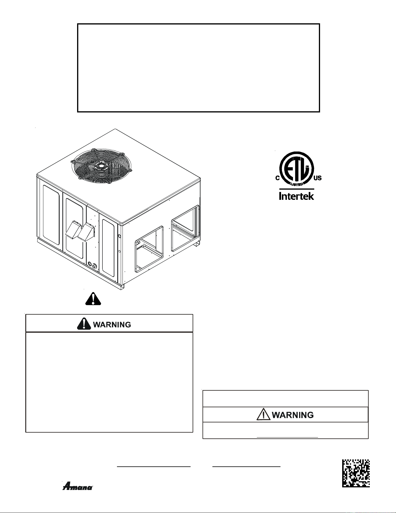
INSTALLATION & OPERATING
INSTRUCTIONS for
A/GPG14 M SERIES W/R410A
SINGLE PACKAGE GAS-ELECTRIC
HEATING & COOLING UNIT
*NOTE: Please contact your distributor or our
website for the applicable Specification
Sheet or Technical Manual referred to in this
manual.
RECOGNIZE THIS SYMBOL AS A SAFETY PRECAUTION.
is a registered trademark of Maytag Corporation or its related companies and is used under license. All rights reserved.
O
NLY
PERSONNEL
THAT
HAVE
BEEN
TRAINED
TO
INSTALL
,
ADJUST
,
SERVICE
OR
REPAIR
(
HEREINAFTER
, “
SERVICE
”)
THE
EQUIPMENT
SPECIFIED
IN
THIS
MANUAL
SHOULD
SERVICE
THE
EQUIPMENT
. T
HE
MANUFACTURER
WILL
NOT
BE
RESPONSIBLE
FOR
ANY
INJURY
OR
PROPERTY
DAMAGE
ARISING
FROM
IMPROPER
SERVICE
OR
SERVICE
PROCEDURES
. I
F
YOU
SERVICE
THIS
UNIT
,
YOU
ASSUME
RESPONSIBILITY
FOR
ANY
INJURY
OR
PROPERTY
DAMAGE
WHICH
MAY
RESULT
. I
N
ADDITION
,
IN
JURISDICTIONS
THAT
REQUIRE
ONE
OR
MORE
LICENSES
TO
SERVICE
THE
EQUIPMENT
SPECIFIED
IN
THIS
MANUAL
,
ONLY
LICENSED
PERSONNEL
SHOULD
SERVICE
THE
EQUIPMENT
. I
MPROPER
INSTALLATION
,
ADJUSTMENT
,
SERVICING
OR
REPAIR
OF
THE
EQUIPMENT
SPECIFIED
IN
THIS
MANUAL
,
OR
ATTEMPTING
TO
INSTALL
,
ADJUST
,
SERVICE
OR
REPAIR
THE
EQUIPMENT
SPECIFIED
IN
THIS
MANUAL
WITHOUT
PROPER
TRAINING
MAY
RESULT
IN
PRODUCT
DAMAGE
,
PROPERTY
DAMAGE
,
PERSONAL
INJURY
OR
DEATH
.
This Forced Air Central Unit Design Complies With
Requirements Embodied in The American National
Standard / National Standard of Canada Shown Below.
ANSI Z21.47•CSA-2.3 Central Furnaces
These installation instructions cover the outdoor
installation of single package gas electric heating and
cooling units. See the Specification Sheet or Technical
Manual applicable to your model* for information
regarding accessories.
Cancer and Reproductive Harm -
www.P65Warnings.ca.gov
PROP 65 WARNING
FOR CALIFORNIA CONSUMERS
0140M00517-A

2
Index
Replacement Parts ................................................................................................................................................................................... 3
ORDERING PARTS ..................................................................................................................................................................................... 3
Safety Instructions .................................................................................................................................................................................... 3
General Information .................................................................................................................................................................................. 6
T
RANSPORTATION DAMAGE .......................................................................................................................................................................... 6
Unit location ............................................................................................................................................................................................... 7
ALL INSTALLATIONS: .................................................................................................................................................................................. 7
GROUND LEVEL INSTALLATIONS ONLY: ............................................................................................................................................................ 7
R
OOFTOP INSTALLATIONS ONLY: .................................................................................................................................................................... 7
R
OOF CURB INSTALLATIONS ONLY: ................................................................................................................................................................ 8
Rigging Details ........................................................................................................................................................................................... 8
Gas Piping .................................................................................................................................................................................................. 8
HIGH A LTITUDE DERATE (U.S. INSTALLATIONS ONLY) ....................................................................................................................................... 8
PIPING ................................................................................................................................................................................................... 9
G
AS PIPING CHECKS ................................................................................................................................................................................. 9
Propane Gas Installations....................................................................................................................................................................... 10
TANKS AND PIPING .................................................................................................................................................................................. 10
Electrical Wiring ...................................................................................................................................................................................... 10
T
HERMOSTAT LOCATION ............................................................................................................................................................................ 10
SINGLE STAGE THERMOSTAT ...................................................................................................................................................................... 11
UNIT VOLTAGE ....................................................................................................................................................................................... 12
H
EAT ANTICIPATOR SETTING ...................................................................................................................................................................... 12
Circulating Air and Filters ....................................................................................................................................................................... 12
AIRFLOW CONVERSION ............................................................................................................................................................................ 12
DUCTWORK .......................................................................................................................................................................................... 12
FILTERS ................................................................................................................................................................................................ 13
Venting ..................................................................................................................................................................................................... 13
FLUE HOOD INSTALLATION ......................................................................................................................................................................... 13
Condensate Drain .................................................................................................................................................................................... 13
CONDENSATE DRAIN CONNECTION .............................................................................................................................................................. 13
Normal Sequences of Operation ............................................................................................................................................................ 13
HEATING ............................................................................................................................................................................................... 13
COOLING .............................................................................................................................................................................................. 14
FAN ONLY ............................................................................................................................................................................................. 14
Startup, Adjustments, and Checks ........................................................................................................................................................ 14
HEATING STARTUP ................................................................................................................................................................................... 14
GAS SUPPLY PRESSURE MEASUREMENT ....................................................................................................................................................... 15
G
AS MANIFOLD PRESSURE MEASUREMENT AND ADJUSTMENT ........................................................................................................................... 17
COOLING STARTUP .................................................................................................................................................................................. 19
Troubleshooting ....................................................................................................................................................................................... 19
IGNITION CONTROL ERROR CODES .............................................................................................................................................................. 19
A
BNORMAL OPERATION - HEATING .......................................................................................................................................................... 19
ABNORMAL OPERATION - COOLING .......................................................................................................................................................... 21
Maintenance ............................................................................................................................................................................................ 21
F
ILTER REPLACEMENT OR CLEANING ............................................................................................................................................................ 21
CABINET FINISH MAINTENANCE ................................................................................................................................................................... 21
CLEAN OUTSIDE COIL (QUALIFIED SERVICER ONLY) ...................................................................................................................................... 21
CONDENSER, EVAPORATOR, AND INDUCED DRAFT MOTORS .............................................................................................................................. 21
FLAME SENSOR (QUALIFIED SERVICER ONLY) ............................................................................................................................................... 21
FLUE PASSAGES (QUALIFIED SERVICER ONLY)............................................................................................................................................... 21
CLEANING FLUE PASSAGES (QUALIFIED SERVICER ONLY) ................................................................................................................................. 21
MAIN BURNER FLAME (QUALIFIED SERVICER ONLY) ....................................................................................................................................... 22
CLEANING BURNERS ................................................................................................................................................................................ 22
Accessories and Functional Parts ......................................................................................................................................................... 22
S
HEET METAL A CCESSORIES ..................................................................................................................................................................... 22
FUNCTIONAL PARTS ................................................................................................................................................................................ 22
GENERAL INFORMATION ............................................................................................................................................................................ 22
APPENDIX ................................................................................................................................................................................................. 29
Unit Dimensions ...................................................................................................................................................................................... 29
Wiring Diagrams...................................................................................................................................................................................... 30
Minimum Clearances .............................................................................................................................................................................. 36
Recommended Filter Sizes ..................................................................................................................................................................... 36
Start0Up Checklist .................................................................................................................................................................................. 38
3
REPLACEMENT PARTS
ORDERING P ARTS
When reporting shortages or damages, or ordering repair
parts, give the complete unit model and serial numbers as
stamped on the unit’s nameplate.
Replacement parts for this appliance are available through
your contractor or local distributor. For the location of your
nearest distributor, consult the white business pages, the
yellow page section of the local telephone book or contact:
HOMEOWNER SUPPORT
GOODMAN MANUFACTURING COMPANY, L.P.
19001 KERMIER ROAD
WALLER, TEXAS 77484
(877) 254-4729
SAFETY INSTRUCTIONS
TO THE INSTALLER
Before installing this unit, please read this manual to
familiarize yourself on the specific items which must be
adhered to, including maximum external static pressure to
unit, air temperature rise, minimum or maximum CFM and
motor speed connections.
Keep this literature in a safe place for future reference.
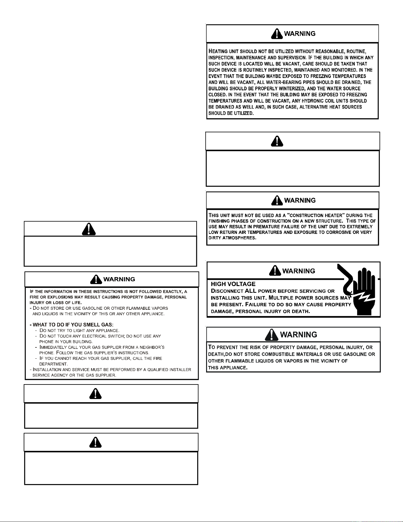
WARNING
D
O NOT CONNECT TO OR USE ANY DEVICE THAT IS NOT DESIGN CERTIFIED
BY GOODMAN FOR USE WITH THIS UNIT. SERIOUS PROPERTY DAMAGE,
PERSONAL INJURY, REDUCED UNIT PERFORMANCE AND/
OR
HAZARDOUS
CONDITIONS MAY RESULT FROM THE USE OF SUCH NON-APPROVED DEVICES.
WARNING
S
HOULD OVERHEATING OCCUR OR THE GAS SUPPLY FAIL TO SHUT OFF, TURN
OFF THE MANUAL GAS SHUTOFF VALVE EXTERNAL TO THE FURNACE BEFORE
TURNING OFF THE ELECTRICAL SUPPLY.
WARNING
T
HIS PRODUCT CONTAINS OR PRODUCES A CHEMICAL OR CHEMICALS WHICH
MAY CAUSE SERIOUS ILLNESS OR DEATH AND WHICH ARE KNOWN TO THE
S
TATE OF
C
ALIFORNIA TO CAUSE CANCER, BIRTH DEFECTS OR OTHER
REPRODUCTIVE HARM.
WARNING
T
O AVOID PROPERTY DAMAGE, PERSONAL INJURY OR DEATH, DO NOT USE
THIS UNIT IF ANY PART HAS BEEN UNDER WATER.
I
MMEDIATELY CALL A
QUALIFIED SERVICE TECHNICIAN TO INSPECT THE FURNACE AND TO REPLACE
ANY PART OF THE CONTROL SYSTEM AND ANY GAS CONTROL HAVING BEEN
UNDER WATER.
4
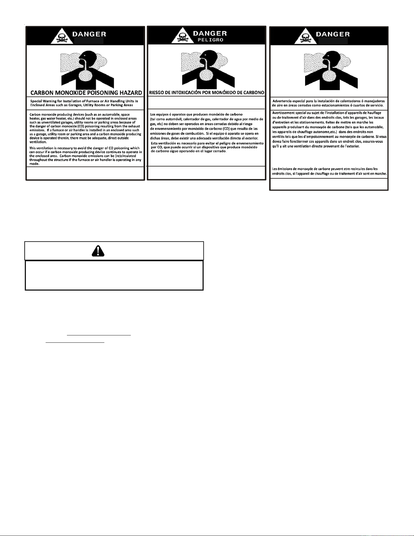
CARBON MONOXIDE POISONING HAZARD
Failure to follow the steps outlined below for each
appliance connected to the venting system being placed
into operation could result in carbon monoxide poisoning
or death.
The following steps shall be followed with each appliance
connected to the venting system placed in operation,
while any other appliances connected to the venting
system are not in operation:
1. Seal any unused openings in the venting system.
2. Inspect the venting system for proper size and
horizontal pitch, as required by the National Fuel Gas
Code, ANSI Z223.1 or the Natural Gas and Propane
Installation Code, CSA B149.1-15 and these
instructions. Determine that there is no blockage or
restriction, leakage, corrosion and other deficiencies
which could cause an unsafe condition.
3. As far as practical, close all building doors and
windows and all doors between the space in which
the appliance(s) connected to the venting system are
located and other spaces of the building.
4. Close fireplace dampers.
5. Turn on clothes dryers and any appliance not
connected to the venting system. Turn on any
exhaust fans, such as range hoods and bathroom
exhausts, so they shall operate at maximum speed.
Do not operate a summer exhaust fan.
6. Follow the lighting instructions. Place the appliance
being inspected in operation. Adjust thermostat so
appliance shall operate continuously.
7. Test for spillage from draft hood appliances at the
draft hood relief opening after 5 minutes of main
burner operation. Use the flame of a match or
candle.
8. If improper venting is observed during any of the
above tests, the venting system must be corrected in
accordance with the National Fuel Gas Code ANSI
Z223.1/NFPA 54 and/or National Gas and Propane
Installation Code CSA B149.1-15.
9. After it has been determined that each appliance
connected to the venting system properly vents
when tested as outlined above, return doors,
windows, exhaust fans, fireplace dampers and any
other gas burning appliance to their previous
conditions of use.
AVERTISSEMENT
RISQUE D'INTOXICATION AU MONOXYDE DE CARBONE
Si les étapes décrites ci-dessous ne sont pas suivies pour
chacun des appareils raccordés au système de ventilation
au moment de sa mise en marche, cela peut entraîner une
intoxication au monoxyde de carbone ou la mort. Les
étapes suivantes doivent être suivies pour chacun des
appareils raccordés au système de ventilation au moment
de sa mise en marche, alors que tous les autres appareils
raccordés au système de ventilation ne sont pas en marche:
1) Sceller toutes les ouvertures inutilisées du système
de ventilation.
2) Inspecter le système de ventilation afin de vérifier si la
taille et l'inclinaison par rapport à l'horizontale sont
conformes aux exigences du National Fuel Gas Code,
ANSI Z223.1/NFPA 54 ou du Code d'installation du gaz
naturel et du propane, CSA B149.1 et à ces instructions.
Vérifier qu'il n'y a pas d'obstruction ou de restriction, de
fuite, de corrosion et d'autres problèmes qui pourraient
entraîner une situation dangereuse.
3) Si possible, fermer toutes les portes et fenêtres du
bâtiment ainsi que toutes les portes séparant l'endroit
où se trouvent les appareils raccordés au système de
ventilation et les autres zones du bâtiment.
4) Fermer le registre des foyers.
5) Mettre les sécheuses en marche ainsi que tous les
autres appareils qui ne sont pas raccordés au système de
ventilation. Mettre en marche tous les ventilateurs de
tirage, comme celui des hottes de cuisine et des salles de
bains, et les régler à la puissance maximale. Ne pas
mettre en marche les ventilateurs d'été.
6) Suivre les instructions d'allumage. Mettre en marche
l'appareil soumis à l'inspection. Régler le thermostat
de manière à ce que l'appareil fonctionne en continu.
7) Vérifier la présence de fuite au niveau de l'ouverture
du coupe-tirage des appareils qui en sont dotés après 5
minutes de fonctionnement du brûleur principal. Utiliser
la flamme d'une allumette ou d'une bougie.
8) Si un problème de ventilation est observé pendant
l'un des essais décrits ci-dessus, des correctifs doivent
être apportés au système de ventilation conformément
au National Fuel Gas Code, ANSI Z223.1/NFPA 54 et (ou)
au Code d'installation du gaz naturel et du propane, CSA
B149.1.
9) Une fois qu'il a été déterminé que chaque appareil
raccordé au système de ventilation fonctionne
correctement au moyen des essais décrits ci-dessus,
les portes, les fenêtres, les ventilateurs, les registres
de foyer et tous les autres appareils de combustion
alimentés au gaz doivent être remis dans leur état
initial.
5
CARBON MONOXIDE POISONING HAZARD
Failure to follow instructions could result in severe personal
injury or death due to carbon-monoxide poisoning, if
combustion products infiltrate into the building. Check that
all openings in the outside wall around the vent (and air
intake) pipe(s) are sealed to prevent infiltration of
combustion products into the building. Check that furnace
vent (and air intake) terminal(s) are not obstructed in any
way during all seasons.
AVERTISSEMENT
R
Si ces directives ne sont pas suivies, cela peut entraîner des
blessures graves ou une intoxication au monoxyde de
carbone pouvant causer la mort, si des produits de
combustion s'infiltrent dans le bâtiment. Vérifier que toutes
les ouvertures pratiquées dans le mur extérieur autour du ou
des tuyaux d'évent (et de la prise d'air) sont scellées de
manière à empêcher l'infiltration de produits de combustion
dans le bâtiment. Veiller à ce que la ou les sorties de l'évent
de l'appareil de chauffage (et la prise d'air) ne soient, en
aucune façon, obstruées, quelle que soit la saison.
ISQUE D'INTOXICATION AU MONOXYDE DE CARBONE
FIRE OR EXPLOSION HAZARD
Failure to follow the safety warnings exactly could result in
serious injury, death or property damage.
Never test for gas leaks with an open flame.
Use a commercially available soap solution made specifically
for the detection of leaks to check all connections. A fire or
explosion may result causing property damage, personal
injury or loss of life.
AVERTISSEMENT
RISQUE D'INCENDIE OU D'EXPLOSION
Si les consignes de sécurité ne sont pas suivies à la lettre,
cela peut entraîner la mort, de graves blessures ou des
dommages matériels.
Ne jamais vérifier la présence de fuites de gaz au moyen
d'une flamme nue. Vérifier tous les raccords en utilisant
une solution savonneuse commerciale conçue
spécialement pour la détection de fuites. Un incendie ou
une explosion risque de se produire, ce qui peut entraîner
la mort, des blessures ou des dommages matériels.
6
GENERAL INFORMATION
WARNING
T
O PREVENT PROPERTY DAMAGE, PERSONAL INJURY OR DEATH, DUE TO FIRE
,
EXPLOSIONS, SMOKE, SOOT, CONDENSATION, ELECTRIC SHOCK OR CARBON
MONOXIDE, THIS UNIT MUST BE PROPERLY INSTALLED, REPAIRED, OPERATED,
AND MAINTAINED.
This unit is approved for outdoor installation ONLY. Rated perfor-
mance is achieved after 20 hours of operation. Rated performance
is delivered at the specified airflow. See outdoor unit specifica-
tion sheet for split system models or product specification sheet
for packaged and light commercial models. Specification sheets
can be found at www.goodmanmfg.com for Goodman
®
brand prod-
ucts or www.amana-hac.com for Amana
®
brand products. Within
either website, please select the residential or commercial prod-
ucts menu and then select the submenu for the type of product to
be installed, such as air conditioners or heat pumps, to access a
list of product pages that each contain links to that model’s speci-
fication sheet.
To assure that your unit operates safely and efficiently, it must be in-
stalled, operated, and maintained in accordance with these installa-
tion and operating instructions, all local building codes and ordinances,
or in their absence, with the latest edition of the National Fuel Gas
Code NFPA54/ANSI Z223.1 and National Standard of Canada CAN/
CSA B149 Installation Codes.
The heating and cooling capacities of the unit should be greater
than or equal to the design heating and cooling loads of the area to
be conditioned. The loads should be calculated by an approved
method or in accordance with A.S.H.R.A.E. Guide or Manual J -
Load Calculations published by the Air Conditioning Contractors
of America.
Obtain from:
American National Standards Institute
25 West 43rd Street, 4th Floor
New York, NY 10036
TRANSPORTATION DAMAGE
Check the carton upon arrival for external damage. If damage is
found, a request for inspection by carrier agent should be made
in writing immediately.
Carefully inspect the unit for damage including damage to the
cabinetry. Any bolts or screws which may have loosened in
transit must be retightened. In the event of damage, the re-
ceiver should:
1. Make notation on delivery receipt of any visible damage
to shipment or container.
2. Notify carrier promptly and request an inspection.
3. In case of concealed damage, carrier should be notified
as soon as possible-preferably within 5 days.
4. File the claim with the following supporting documents:
a. Original Bill of Lading, certified copy, or indemnity bond.
b. Original paid freight bill or indemnity in lieu thereof.
c. Original invoice or certified copy thereof, showing trade
and other discounts or reductions.
d. Copy of the inspection report issued by carrier
representative at the time damage is reported to the
carrier. The carrier is responsible for making prompt
inspection of damage and for a thorough investigation
of each claim. The distributor or manufacturer will not
accept claims from dealers for transportation damage.
NOTE: When inspecting the unit for transportation damage, re-
move all packaging materials. Recycle or dispose of the pack-
aging material according to local codes.
B10259-216
CO can cause serious illness including permanent brain
damage or death.
Advertencia especial para la instalación de calentadores ó manejadoras
de aire en áreas cerradas como estacionamientos ó cuartos de servicio.
B10259-216
El monóxido de carbono puede causar enfermedades severas
como daño cerebral permanente ó muerte.
Las emisiones de monóxido de carbono pueden circular a través
del ap arato cu ando se opera en cualquier modo.
B10259-216
RISQUE D'EMPOISONNEMENT AU
MONOXYDE DE CARBONE
Le monoxyde de
des
carbone peut causer des maladies graves telles que
dommages permanents au cerveau et meme la mort.
Cette ventilation est nécessaire pour éviter le danger d'intoxication
au CO pouvant survenir si un appareil produisant du monoxyde
de carbone continue de fonctionner au sein de la zone confinée.
7
UNIT LOCATIONS
WARNING
T
O PREVENT POSSIBLE EQUIPMENT DAMAGE, PROPERTY DAMAGE, PERSONAL
INJURY OR DEATH, THE FOLLOWING BULLET POINTS MUST BE OBSERVED
WHEN INSTALLING THE UNIT.
ALL INSTALLATIONS:
• For proper flame pattern within the heat exchanger and
proper condensate drainage, the unit must be mounted
level.
• The flue outlet hood must be at least 12 inches from any
opening through which flue gases could enter a building,
and at least three feet above any forced air inlet located
within ten feet. The economizer/manual fresh air intake/
motorized fresh air intake and combustion air inlet
mounted on the unit are not affected by this restriction.
• To avoid possible corrosion of the heat exchanger, do not
locate the unit in an area where the outdoor air (i.e.
combustion air for the unit) will be frequently contaminated
by compounds containing chlorine or fluorine. Common
sources of such compounds include swimming pool
chemicals and chlorine bleaches, paint stripper,
adhesives, paints, varnishes, sealers, waxes (which are
not yet dried) and solvents used during construction and
remodeling. Various commercial and industrial processes
may also be sources of chlorine/fluorine compounds.
• To avoid possible illness or death of the building occupants,
do NOT locate outside air intake device (economizer,
manual fresh air intake, motorized fresh air intake) too
close to an exhaust outlet, gas vent termination, or
plumbing vent outlet. For specific distances required,
consult local codes.
• Allow minimum clearances from the enclosure for fire
protection, proper operation, and service access (see
appendix). These clearances must be permanently
maintained.
• The combustion air inlet and flue outlet hoods on the unit
must never be obstructed. If used, do not allow the
economizer/manual fresh air damper/ motorized fresh air
damper to become blocked by snow or debris. In some
climates or locations, it may be necessary to elevate the
unit to avoid these problems.
• Damper must be on open position when appliance main
burner(s) is operating.
Le registre doit être ouvert lorsque tout brûleur principal
de l’appareil est en état de fonctionnement.
• When the unit is heating, the temperature of the return air
entering the unit must be between 50° F and 100° F.
• Units manufactured on or after May 1, 2017 are not permitted
to be used in Canada for heating of buildings or structures
under construction.
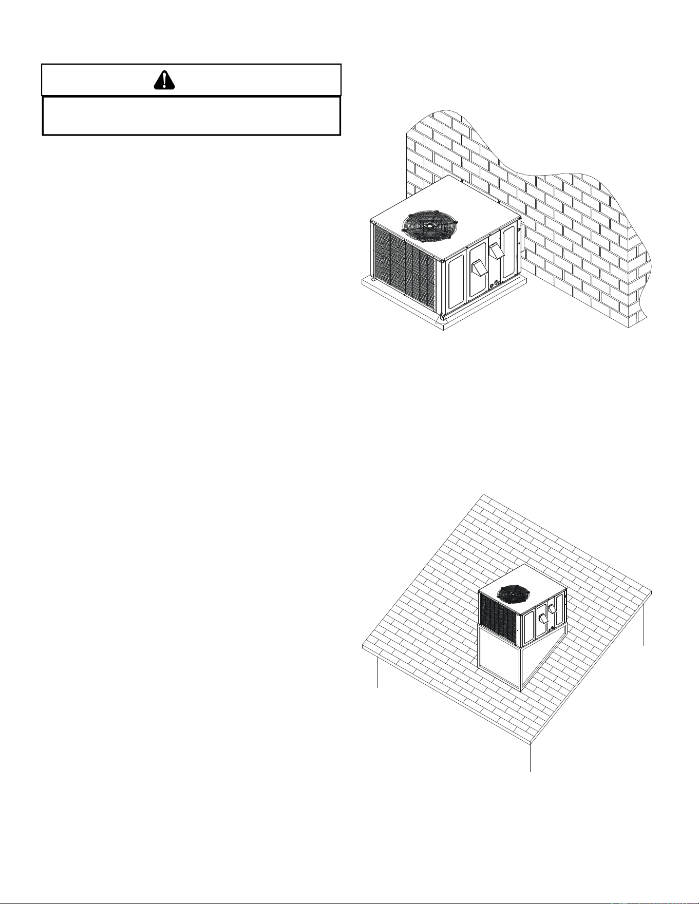
GROUND LEVEL I NSTALLATIONS O NLY:
• When the unit is installed on the ground adjacent to the
building, a level concrete (or equal) base is recommended.
Prepare a base that is 3” larger than the package unit
footprint and a minimum of 3” thick.
• The base should also be located where no runoff of water
from higher ground can collect in the unit.
• The top of the unit should be completely unobstructed. If
units are to be located under an overhang, there should
be a minimum of 48” clearance and provisions made to
deflect the warm discharge air out from the overhang.
Outside Slab Installation
ROOFTOP I NSTALLATIONS ONLY:
NOTE: To ensure proper condensate drainage, unit must be
installed in a level position.
• To avoid possible property damage or personal injury, the
roof must have sufficient structural strength to carry the
weight of the unit(s) and snow or water loads as required
by local codes. Consult a structural engineer to determine
the weight capabilities of the roof.
Rooftop Installation
• The unit may be installed directly on wood floors or on
Class A, Class B, or Class C roof covering material.
• To avoid possible personal injury, a safe, flat surface for
service personnel should be provided.
8
ROOF CURB I NSTALLATIONS O NLY:
• Sufficient structural support must be determined prior to
locating and mounting the curb and package unit.
• Ductwork must be constructed using industry guidelines.
The duct work must be placed into the roof curb before
mounting the package unit.
• Curb insulation, cant strips, flashing and general roofing
material are furnished by the contractor.
Roof Curb Installation
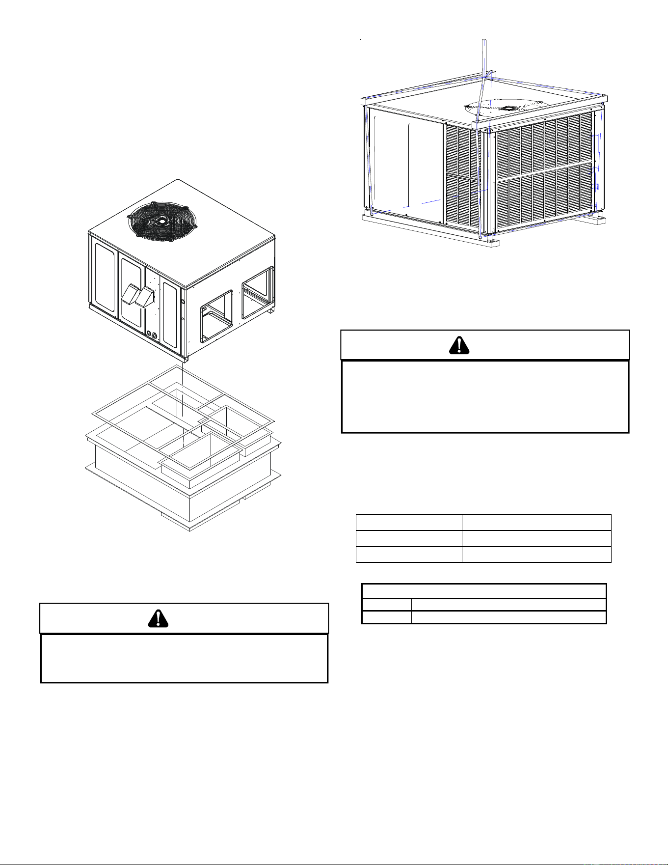
RIGGING DETAILS
WARNING
T
O PREVENT PROPERTY DAMAGE, THE UNIT SHOULD REMAIN IN AN UPRIGHT
POSITION DURING ALL RIGGING AND MOVING OPERATIONS.
T
O FACILITATE
LIFTING AND MOVING WHEN A CRANE IS USED, PLACE THE UNIT IN AN
ADEQUATE CABLE SLING.
Important: If using bottom discharge with roof curb, ductwork
should be attached to the curb prior to installing the unit. Ductwork
dimensions are shown in roof curb installation instructions.
Refer to the Roof Curb Installation Instructions for proper curb in-
stallation. Curbing must be installed in compliance with the National
Roofing Contractors Association Manual.
Lower unit carefully onto roof mounting curb. While rigging unit,
center of gravity will cause condenser end to be lower than supply
air end.
Rigging
GAS PIPING
IMPORTANT NOTE: This unit is factory set to operate on natural
gas at the altitudes shown on the rating plate.
WARNING
T
O AVOID PROPERTY DAMAGE, PERSONAL INJURY OR DEATH WHEN EITHER
USING PROPANE GAS ALONE OR AT HIGHER ALTITUDES, OBTAIN AND INSTALL
THE PROPER CONVERSION KIT(S).
F
AILURE TO DO SO CAN RESULT IN
UNSATISFACTORY OPERATION AND/OR EQUIPMENT DAMAGE.
H
IGH ALTITUDE
KITS ARE FOR
U
.
S
. INSTALLATIONS ONLY AND ARE NOT APPROVED FOR USE
IN
C
ANADA.
The rating plate is stamped with the model number, type of gas
and gas input rating. Make sure the unit is equipped to operate on
the type of gas available. Conversion to LP gas is permitted with
the use of the factory authorized conversion kit LPM-07, for use
with single stage models, or LPM-08, for use with two-stage mod-
els. See table below.
LP Conversion Kit Model
LPM-07 Single Stage Heating Models
LPM-08 Two-Stage Heating Models
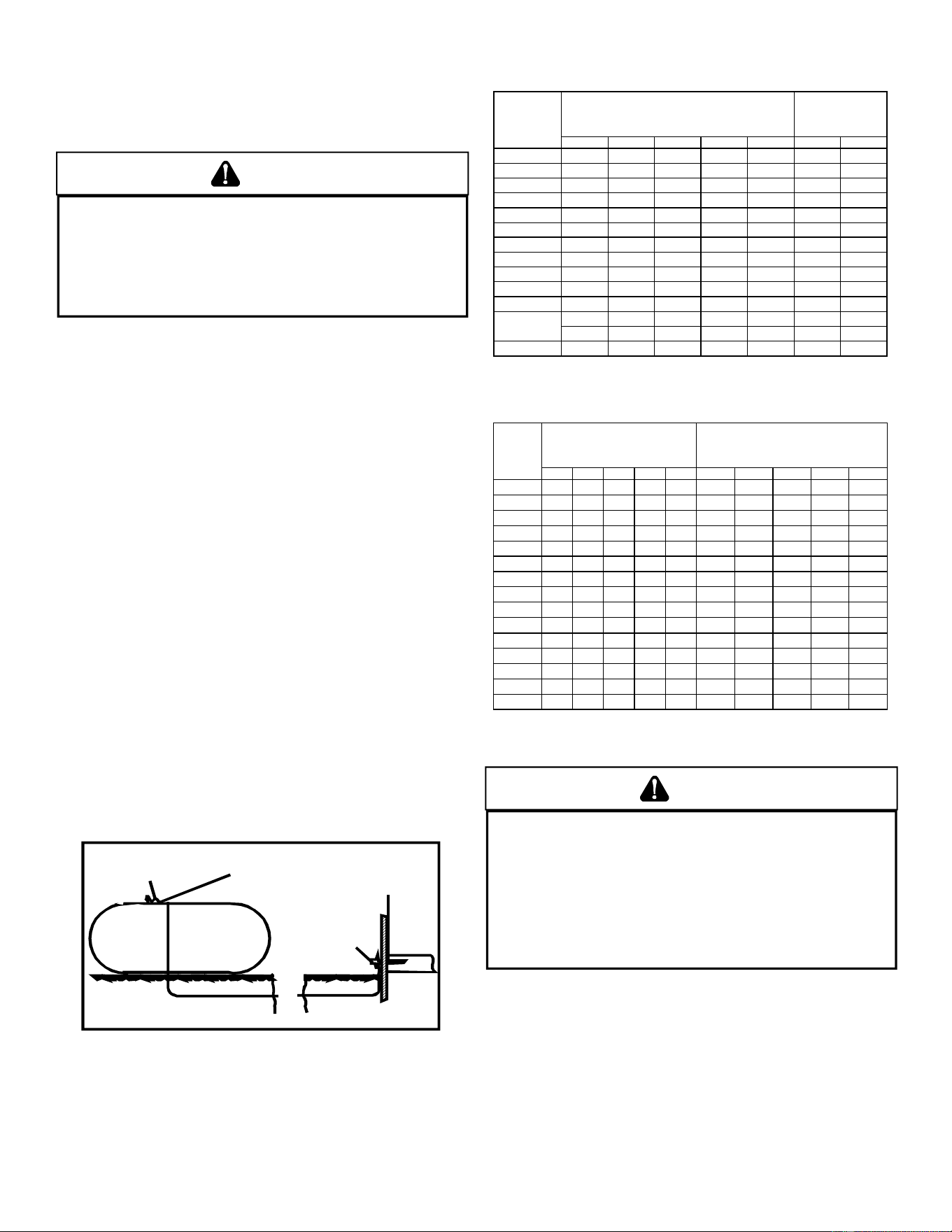
Inlet Gas Pressure
Natural Min. 5.0" W.C., Max. 10.0" W.C.
Propane Min. 11.0" W.C., Max. 13.0" W.C.
Inlet Gas Pressure Must Not Exceed the Maximum Value Shown
in Table Above.
The minimum supply pressure should not vary from that shown in
the table above because this could prevent the unit from having
dependable ignition. In addition, gas input to the burners must not
exceed the rated input shown on the rating plate. Overfiring of the
unit could result in premature heat exchanger failure.
HIGH ALTITUDE D ERATE (U.S. INSTALLATIONS ONLY)
IMPORTANT NOTE: The gas/electric units naturally derate with al-
titude. Do not attempt to increase the firing rate by changing ori-
fices or increasing the manifold pressure. This can cause poor
combustion and equipment failure. At all altitudes, the manifold
pressure must be within 0.3 inches W.C. of that listed on the name-
plate for the fuel used. At all altitudes and with either fuel, the air
temperature rise must be within the range listed on the unit name-
plate.
9
Refer to the Installation Manual provided with the LP kit for conver-
sion from natural gas to propane gas and for altitude adjustments.
NOTE: Up to 2,000 feet, no changes are required; above 2,000 feet,
please refer to the gas/electric package unit specification sheets
for required kit(s).
Installation of the gas/electric unit at altitudes above 2000 ft (610m)
shall be made in accordance with the listed High Altitude Conver-
sion Kit available for this gas/electric unit.
Installation de l’unité gaz/électrique à des altitude supérieures à
2000 ft (610m) doit être faite conformément à la Haute Altitude Kit
de Conversion disponible pour cette unité gaz/électrique.
PIPING
IMPORTANT NOTE: To avoid possible unsatisfactory operation or
equipment damage due to under firing of equipment, do not un-
dersize the natural/propane gas piping from the meter/tank to the
unit. When sizing a trunk line, include all appliances on that line
that could be operated simultaneously.
The rating plate is stamped with the model number, type of gas
and gas input rating. Make sure the unit is equipped to operate on
the type of gas available. The gas line installation must comply
with local codes, or in the absence of local codes, with the latest
edition of the National Fuel Gas Code NFPA 54/ANSI Z223.1.
Natural Gas Connection
Length of
Pipe in Feet 1/2 3/4 1 1 1/4 1 1/2
10 132 278 520 1050 1600
20 92 190 350 730 1100
30 73 152 285 590 980
40 63 130 245 500 760
50 56 115 215 440 670
60 50 105 195 400 610
70 46 96 180 370 560
80 43 90 170 350 530
90 40 84 160 320 490
100
38
79
150
305
460
Pressure = .50 PSIG or less and Pressure Drop of 0.3" W.C. (Based
on 0.60 Specific Gravity Gas)
Natural Gas Capacity of Pipe
in Cubic Feet of Gas Per Hour (CFH)
Nominal Black Pipe Size (inches)
BTUH Furnace Input
Heating Value of Gas (BTU/Cubic
Foot)
CFH =
Refer to the Proper Piping Practice drawing for the general layout
at the unit. The following rules apply:
1. Use black iron pipe and fittings for the supply piping. The
use of a flex connector and/or copper piping is permitted
as long as it is in agreement with local codes.
2. Use pipe joint compound on male threads only. Pipe joint
compound must be resistant to the action of the fuel used.
3. Use ground joint unions.
4. Install a drip leg to trap dirt and moisture before it can
enter the gas valve. The drip leg must be a minimum of
three inches long.
5. Use two pipe wrenches when making connection to the
gas valve to keep it from turning.
6. Install a manual shut-off valve in a convenient location
(within six feet of unit) between the meter and the unit.
7. Tighten all joints securely.
8. The unit must be connected to the building piping by one
of the following methods:
• Rigid metallic pipe and fittings
• Semirigid metallic tubing and metallic fittings (Aluminum
alloy tubing must not be used in exterior locations)
• Listed gas appliance connectors used in accordance
with the terms of their listing that are completely in the
same room as the equipment
• In the prior two methods above the connector or tubing
must be protected from physical and thermal damage.
Aluminum alloy tubing and connectors must be coated to
protect against external corrosion when in contact with
masonry, plaster or insulation or are subject to repeated
wettings by liquids (water - not rain water, detergents or
sewage)
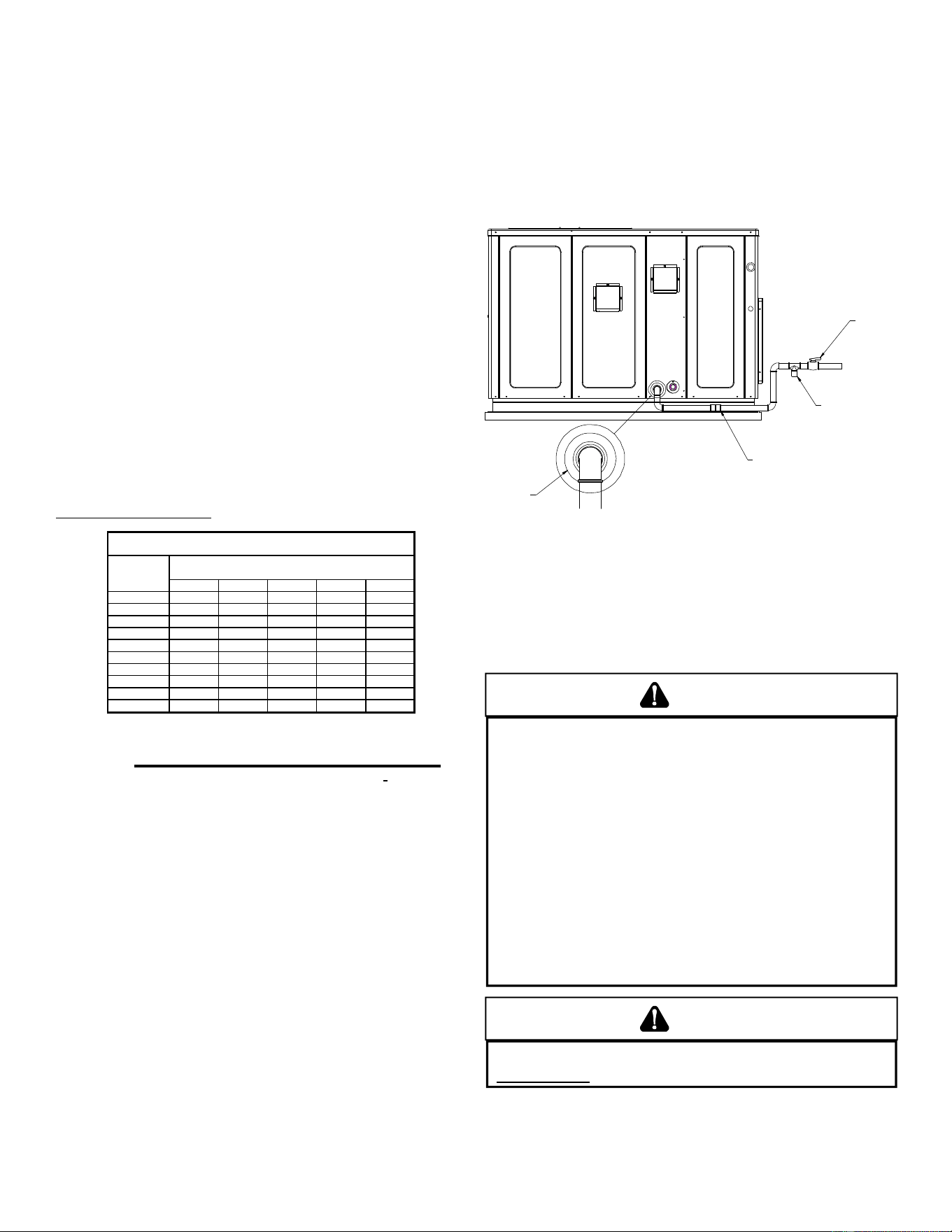
DRIP LEG
MANUAL
SHUT-OF
F
VALVE
GROUND JOINT UNION
(INSTALLED AHEAD OF GAS VALVE)
GROMMET
Proper Piping Practice
NOTE: The unit gas supply entrance is factory sealed with plugs.
Keep plugs in place until gas supply is ready to be installed. Once
ready, replace the plugs with the supplied grommets and install gas
supply line.
GAS PIPING CHECKS
CAUTION
T
O PREVENT PROPERTY DAMAGE OR PERSONAL INJURY DUE TO FIRE, THE
FOLLOWING INSTRUCTIONS MUST BE PERFORMED REGARDING GAS
CONNECTIONS AND PRESSURE TESTING:
•
T
HE UNIT AND ITS GAS CONNECTIONS MUST BE LEAK TESTED BEFORE
PLACING IN OPERATION.
B
ECAUSE OF THE DANGER OF EXPLOSION OR
FIRE, NEVER USE A MATCH OR OPEN FLAME TO TEST FOR LEAKS.
N
EVER
EXCEED SPECIFIED PRESSURES FOR TESTING.
H
IGHER PRESSURE MAY
DAMAGE GAS VALVE AND CAUSE OVERFIRING WHICH MAY RESULT IN
PREMATURE HEAT EXCHANGE FAILURE.
•
T
HIS UNIT AND ITS SHUT-OFF VALVE MUST BE DISCONNECTED FROM
THE GAS SUPPLY DURING ANY PRESSURE TESTING OF THAT SYSTEM AT
TEST PRESSURES IN EXCESS OF 1/2
PSIG
(3.48 K
P
A).
•
T
HIS UNIT MUST BE ISOLATED FROM THE GAS SUPPLY SYSTEM BY
CLOSING ITS MANUAL SHUT-OFF VALVE DURING ANY PRESSURE
TESTING OF THE GAS SUPPLY PIPING SYSTEM AT TEST PRESSURES
EQUAL TO OR LESS THAN 1/2
PSIG
(3.48 K
P
A).
WARNING
T
O AVOID PROPERTY DAMAGE OR PERSONAL INJURY, BE SURE THERE IS
NO OPEN FLAME IN THE VICINITY DURING AIR BLEEDING.
There will be air in the gas supply line after testing for leaks
on a new installation. Therefore, the air must be bled from the
line by loosening the ground joint union until pure gas is
expelled. Tighten union and wait for five minutes until all gas
has been dissipated in the air. Be certain there is no open
10
Sizing Between First and Second Stage Regulator
Maximum Propane Capacities listed are based on 1 PSIG Pressure Drop at 10
PSIG Setting. Capacities in 1,000 BTU/HR
3/8" 1/2" 5/8" 3/4" 7/8" 1/2" 3/4"
30 309 700 1,303 2,205 3,394 1,843 3,854
40 265 599 1,115 1,887 2,904 1,577 3,298
50 235 531 988 1,672 2,574 1,398 2,923
60 213 481 896 1,515 2,332 1,267 2,649
70 196 446 824 1,394 2,146 1,165 2,437
80 182 412 767 1,297 1,996 1,084 2,267
90 171 386 719 1,217 1,873 1,017 2,127
100 161 365 679 1,149 1,769 961 2,009
150 130 293 546 923 1,421 772 1,613
200 111 251 467 790 1,216 660 1,381
250 90 222 414 700 1,078 585 1,224
300 89 201 378 634 976 530 1,109
350 82 185 345 584 898 488 1,020
400 76 172 321 543 836 454 949
To convert to Capacities at 15 PSIG Settings -- Multiply by 1.130
To convert to Capacities at 5 PSIG Settings -- Multiply by 0.879
PIPE OR
TUBING
LENGTH,
FEET
NOMINAL PIPE SIZE
,
SCHEDULE 40
TUBING SIZE, O.D., TYPE L
Sizing Between Single or Second Stage Regulator and Appliance*
Maximum Propane Capacities Listed are Based on 1/2" W.C. Pressure Drop at
11" W.C. Setting. Capacities in 1,000 BTU/HR
3/8" 1/2" 5/8" 3/4" 7/8" 1/2" 3/4" 1" 1-1/4" 1-1/2"
10 49 110 206 348 539 291 608 1,146 2,353 3,525
20 34 76 141 239 368 200 418 788 1,617 2,423
30 27 61 114 192 296 161 336 632 1,299 1,946
40 23 52 97 164 253 137 284 541 1,111 1,665
50 20 46 86 146 224 122 255 480 985 1,476
60 19 42 78 132 203 110 231 436 892 1,337
80 16 36 67 113 174 94 198 372 764 1,144
100 14 32 59 100 154 84 175 330 677 1,014
125 12 28 52 89 137 74 155 292 600 899
150 11 26 48 80 124 67 141 265 544 815
200 10 22 41 69 106 58 120 227 465 697
250 9 19 36 61 94 51 107 201 412 618
300 8 18 33 55 85 46 97 182 374 560
350 7 16 30 51 78 43 89 167 344 515
400 7 15 28 47 73 40 83 156 320 479
*DATA IN ACCORDANCE WITH NFPA PAMPHLET NO. 54
NOMINAL PIPE SIZE,
SCHEDULE 40
TUBING SIZE, O.D., TYPE L
PIPE OR
TUBING
LENGTH,
FEET
Table 3 - Propane Gas Pipe Sizing
WARNING
T
O PREVENT PROPERTY DAMAGE OR SERIOUS PERSONAL INJURY DUE TO
FIRE OR EXPLOSION CAUSED BY A PROPANE GAS LEAK, INSTALL A GAS
DETECTING WARNING DEVICE.
I
F THE PROPANE GAS UNIT IS INSTALLED IN AN EXCAVATED AREA OR A
CONFINED SPACE, A WARNING DEVICE IS REQUIRED DUE TO:
•
P
ROPANE GAS IS HEAVIER THAN AIR AND ANY LEAKING GAS CAN
SETTLE IN ANY LOW AREAS OR CONFINED SPACES.
•
P
ROPANE GAS ODORANT MAY FADE, MAKING THE GAS UNDETECTABLE
EXCEPT WITH A WARNING DEVICE.
ELECTRICAL WIRING
THERMOSTAT L OCATION
Mount the thermostat approximately five feet above the floor,
in an area that has an inside, vibration-free wall and has
good air circulation.
Movement of air must not be obstructed by furniture, door,
draperies, etc. The thermostat must not be mounted where it
will be affected by drafts, hot or cold water pipes or air ducts in
walls, radiant heat from fireplace, lamps, the sun, television,
flame in the vicinity during air bleeding procedure. The unit is
placed in operation by closing the main electrical disconnect
switch for the unit.
PROPANE GAS INSTALLATIONS
WARNING
TO AVOID PROPERTY DAMAGE, PERSONAL INJURY OR DEATH DUE TO FIRE
OR EXPLOSION CAUSED BY A PROPANE GAS LEAK, INSTALL A GAS
DETECTING WARNING DEVICE.
S
INCE RUST CAN REDUCE THE LEVEL
OF ODORANT IN PROPANE GAS, A GAS DETECTING WARNING DEVICE
IS THE ONLY RELIABLE WAY TO DETECT A PROPANE GAS LEAK.
C
ONTACT A LOCAL PROPANE GAS SUPPLIER ABOUT INSTALLING A
GAS DETECTING WARNING DEVICE.
IMPORTANT NOTE: Propane gas conversion kits must be
installed to convert units to propane gas.
All propane gas equipment must conform to the safety
standards of the National Board of Fire Underwriters (See
NBFU Manual 58).
For satisfactory operation, propane gas supply pressure must
be within 9.7 - 10.3 inches W.C. at the manifold with all gas
appliances in operation. Maintaining proper gas pressure
depends on three main factors:
1. Vaporization rate, which depends on (a) temperature of
the liquid, and (b) wetted surface area of the container or
containers.
2. Proper pressure regulation.
3. Pressure drop in lines between regulators, and between
second stage regulator and the appliance. Pipe size
required will depend on length of pipe run and total load of
all appliances.
TANKS AND PIPING
Complete information regarding tank sizing for vaporization,
recommended regulator settings and pipe sizing is available
from most regulator manufacturers and propane gas
suppliers.
Since propane gas will quickly dissolve white lead or most
standard commercial compounds, special pipe dope must be
used. Shellac base compounds resistant to the actions of
liquefied petroleum gases such as Gasolac
®
, Stalactic
®
,
Clyde’s
®
or John Crane
®
are satisfactory.
See below for typical propane gas piping.
200 PSIG
Maximum
5 to 15 PSIG
(20 PSIG Max.)
Continuous
11" W.C.
Second Stage
Regulator
First Stage
Regulator
Typical Propane Gas Piping
11
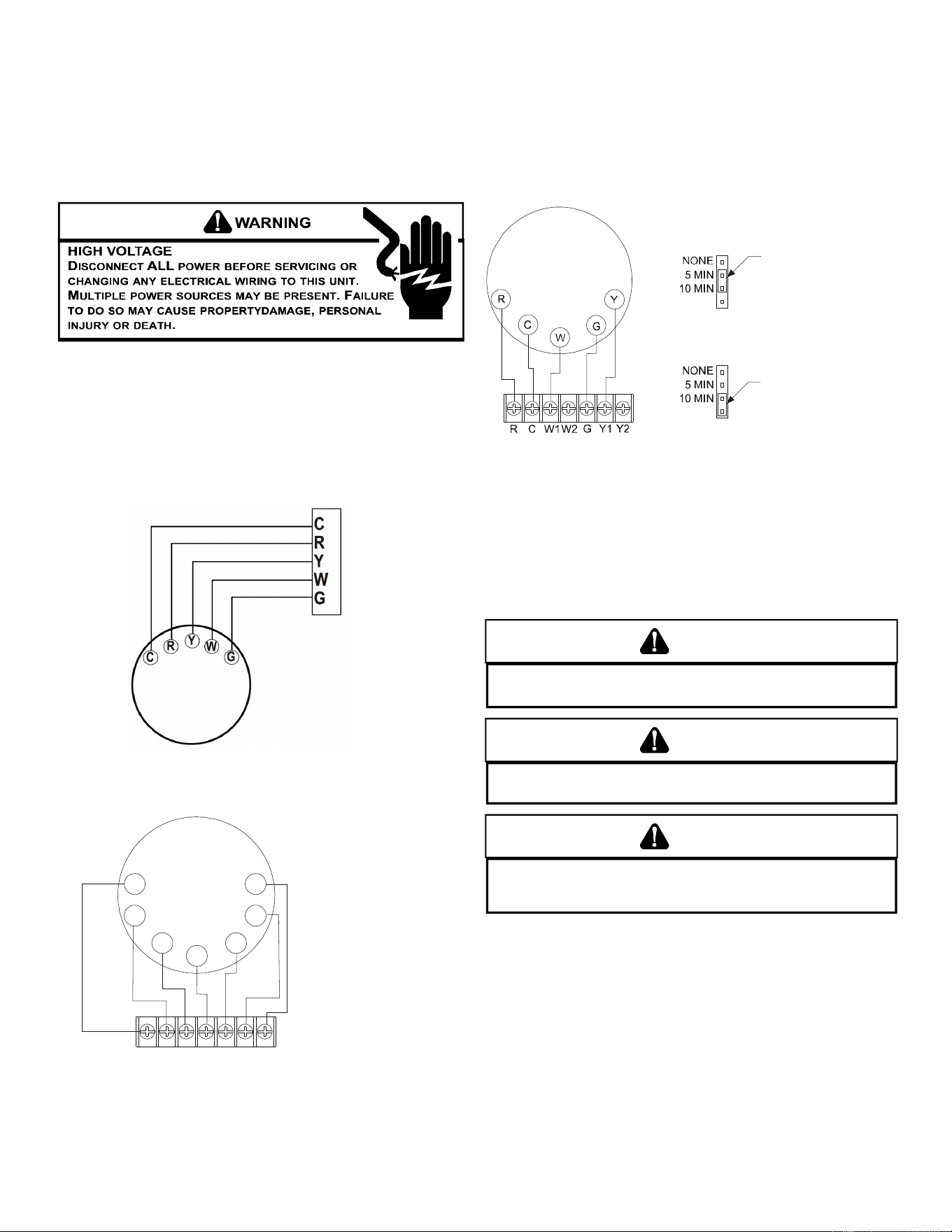
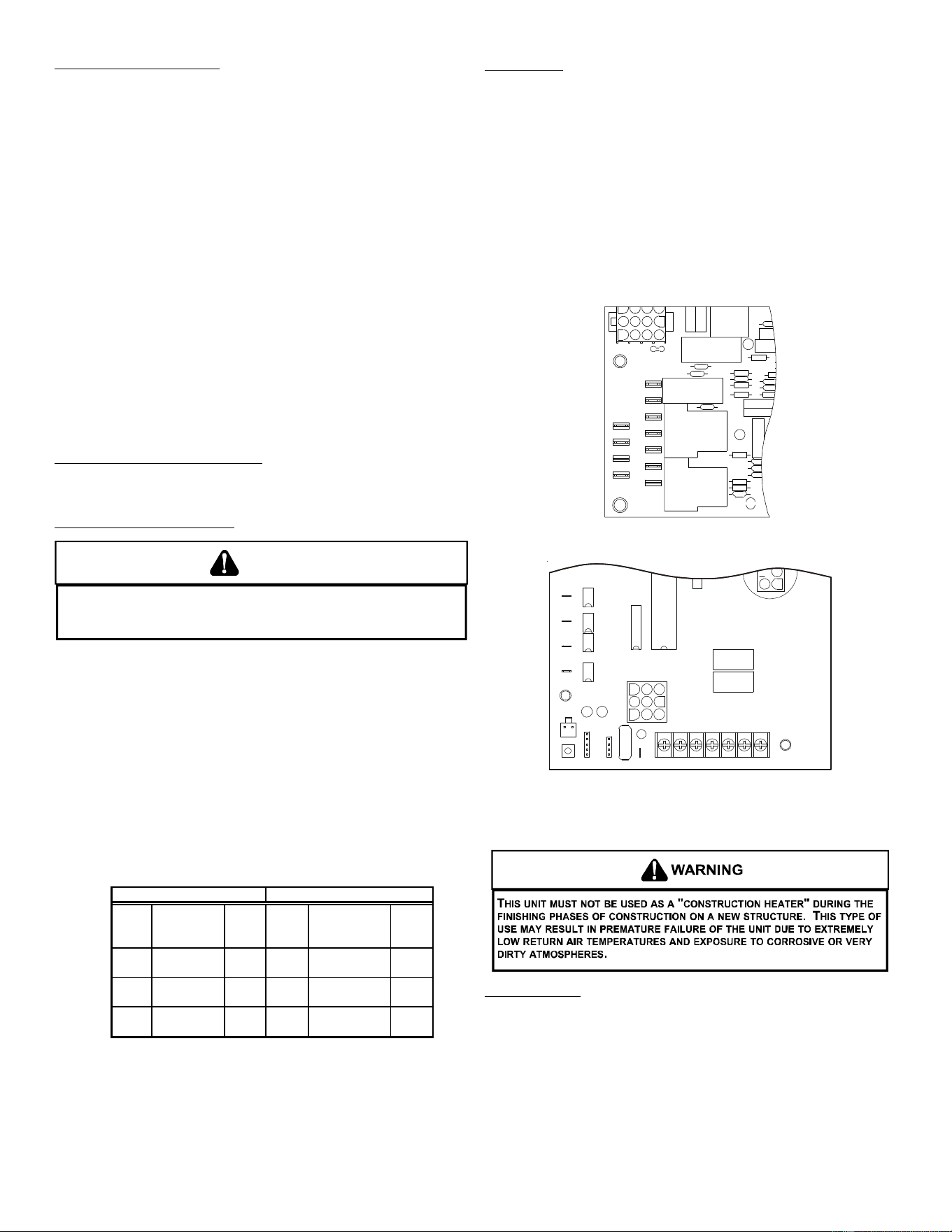
SINGLE STAGE THERMOSTAT - TWO-STAGE MODELS
To use a single stage thermostat, move jumper located to the
left of the terminal strip labeled “Stage Delay” from NONE to
“5” or “10” minutes. This selection will cause the control to
run on low stage for the selected time (5 or 10 minutes) then
shift to HIGH STAGE. This option controls both cooling and
heating modes. If the jumper is not moved, only low-stage
cool and low-stage heat will operate.
5 MINUTE DELAY
PERIOD WITH
JUMPER IN THIS
POSITION
10 MINUTE DELAY
PERIOD WITH
JUMPER IN THIS
POSITION
Two-Stage Heating (timed) and Two-Stage Cooling (timed)
with Single Stage Thermostat Diagram
Refer to the unit wiring diagram for electrical connections.
When installed, the unit must be electrically grounded in
accordance with local codes or in the absence of local codes,
with the National Electrical Code, ANSI/NFPA No. 70, and/or
the CSA C22.1 Electrical Code. Ensure low voltage
connections are waterproof.
WARNING
T
O AVOID THE RISK OF ELECTRICAL SHOCK, WIRING TO THE UNIT MUST BE
POLARIZED AND GROUNDED.
CAUTION
T
O AVOID PROPERTY DAMAGE OR PERSONAL INJURY DUE TO FIRE, USE
ONLY COPPER CONDUCTORS.
CAUTION
T
O PREVENT IMPROPER AND DANGEROUS OPERATION DUE TO WIRING ERRORS,
LABEL ALL WIRES PRIOR TO DISCONNECTION WHEN SERVICING CONTROLS.
V
ERIFY PROPER OPERATION AFTER SERVICING.
For unit protection, use a time delay fuse or HACR circuit
breaker that is in excess of the circuit ampacity, but less than
or equal to the maximum overcurrent protection device. DO
NOT EXCEED THE MAXIMUM OVERCURRENT DEVICE SIZE
SHOWN ON UNIT DATA PLATE.
All line voltage connections must be made through
weatherproof fittings. All exterior power supply and ground
wiring must be in approved weatherproof conduit. Low voltage
wiring from the unit control panel to the thermostat requires
coded cable. See below for ground level and rooftop wiring.
etc. Consult the Instruction Sheet packaged with thermostat
for mounting instructions.
Five ton models have two stages of heating and two stages of
mechanical cooling. Units which have economizers may use
thermostats with two or three stages of cooling.
All other units have one stage of heating and one stage of
mechanical cooling. Units which have economizers may use
thermostats with one or two stages of cooling.
The units are designed for operation on 60 hertz current and
at voltages as shown on the rating plate. All internal wiring in
the unit is complete. It is necessary to bring in the power
supply to the contactor as shown on the unit wiring diagram
which is supplied with each unit. 24 volt wiring must be
connected between the unit control panel and the room
thermostat.
Thermostat Wiring - Single Stage Models
From
Uni
t
Single Stage Heating & Cooling Thermostat Diagram
Thermostat Wiring - Two Stage Models
R
C
W1
W2
G
Y1
Y2
R
Y2
CY1
W1
G
W2
Furnace Integrated
Control Module
Thermostat
Two-Stage Heating
with
Two-Stage Cooling
(
(
Two-Stage Heating with Two-Stage Cooling
Thermostat Diagram
12
Electrical Power Directly To Junction Box
E
lectrical Power Routed Through Bottom of Unit
Note:Junction box location
shown is optional and is
for illustration purposes onl
y.
JUNCTION BOX
Typical Electrical Wiring Unit Voltage
UNIT VOLTAGE
The unit transformer is factory connected for 230V operation.
If the unit is to operate on 208V, reconnect the transformer
primary lead as shown on the unit wiring diagram.
HEAT A NTICIPATOR S ETTING
The heat anticipator is to be set by measuring the load
(amperage) at the “R” circuit. Follow the instructions provided
by the thermostat for more details.
CIRCULATING AIR AND FILTERS
AIRFLOW CONVERSION
Units can easily be converted from horizontal to down-
discharge airflow delivery. In down-discharge or high static
installations, the installer should measure the total external
static and review the blower performance charts before
performing the installation. In some installations it will be
necessary to change the blower speed to provide proper air
flow.
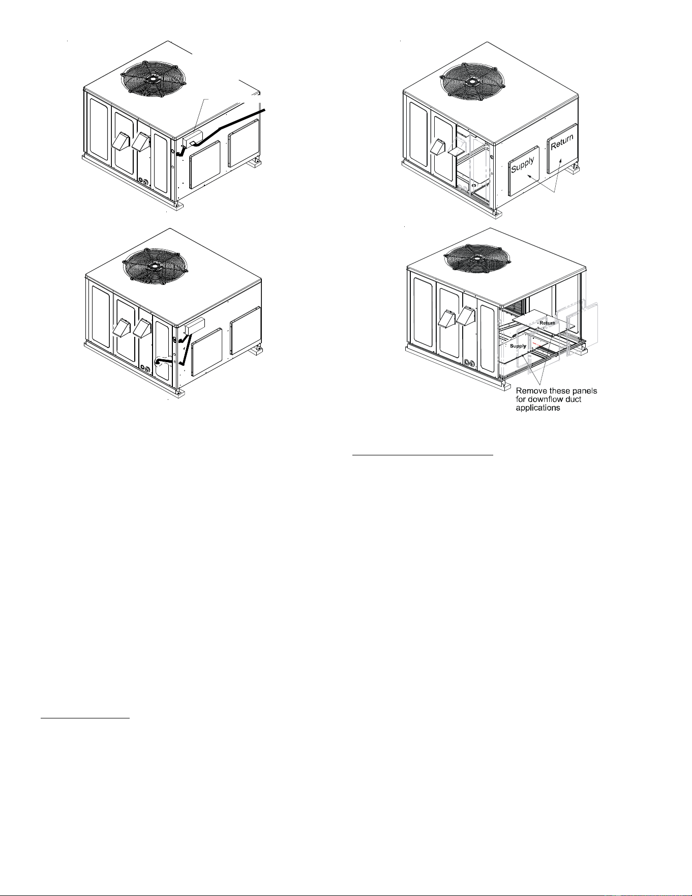
Horizontal Air Flow
Single phase models are shipped without horizontal duct
covers. If needed, these kits may be ordered through
Goodman’s Service Parts department.
For 3-phase models only, remove supply and return duct
covers which are attached to the unit as shown below.
R
emove these cove
rs
f
or horizontal duct
applications
Duct Cover Installation
Down Discharge Applications
Cut insulation around bottom openings and remove panels
from the bottom of the unit, saving the screws holding the
panels in place.
NOTE: Single phase models require installation of horizontal
duct kit #20464501PDGK (medium chassis) and
#20464502PDGK (large chassis).
DUCTWORK
Duct systems and register sizes must be properly designed
for the C.F.M. and external static pressure rating of the unit.
Ductwork should be designed in accordance with the
recommended methods of Air Conditioning Contractors of
America Manual D (Residential) or Manual Q (Commercial).
All ductwork exposed to the outdoors must include a
weatherproof barrier and adequate insulation.
A duct system should be installed in accordance with
Standards of the National Board of Fire Underwriters for the
Installation of Air Conditioning, Warm Air Heating and
Ventilating Systems. Pamphlets No. 90A and 90B.
13
The supply duct from the unit through a wall may be installed
without clearance. However, minimum unit clearances as
shown in the appendix must be maintained. The supply duct
should be provided with an access panel large enough to
inspect the air chamber downstream of the heat exchanger. A
cover should be tightly attached to prevent air leaks.
For duct flange dimensions on the unit refer to the Unit
Dimension illustration in the appendix.
For down-discharge applications, the ductwork should be
attached to the roof curb prior to installing the unit. Ductwork
dimensions are shown in the roof curb installation manual.
If desired, supply and return duct connections to the unit may
be made with flexible connections to reduce possible unit
operating sound transmission.
FILTERS
CAUTION
T
O PREVENT PROPERTY DAMAGE DUE TO FIRE AND LOSS OF
EQUIPMENT EFFICIENCY OR EQUIPMENT DAMAGE DUE TO DUST AND LINT
BUILD UP ON INTERNAL PARTS, NEVER OPERATE UNIT WITHOUT AN AIR
FILTER INSTALLED IN THE RETURN AIR SYSTEM.
Even though a return air filter is not supplied with this unit,
there must be a means of filtering all return air. All units may
be externally filtered.
Refer to the unit filter size chart in the appendix for filter size
information.
Filters installed external to the unit should be sized in
accordance with their manufacturer recommendations. A
throwaway filter must be sized for a maximum face velocity of
300 feet per minute.
Filter Installation
Important: When installing a filter, the air flow arrows on the
filter must point toward the circulator blower.
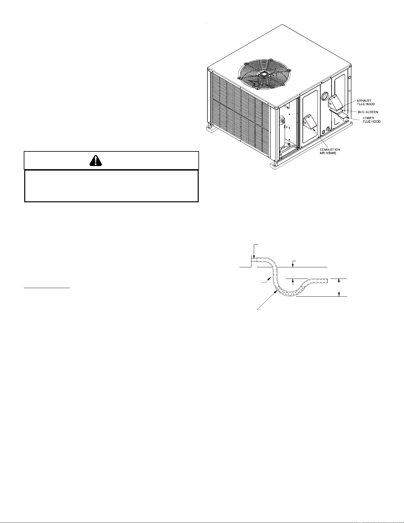
VENTING
NOTE: Venting is self-contained. Do not modify or block.
FLUE H OOD I NSTALLATION
Install the exhaust flue hood and combustion air intake hood
prior to operation of the unit.
To install the flue hood cover, please refer to the installation
instructions, included in the flue hood assembly package
located in the blower compartment.
Flue Hood and Bug Screen Installation
CONDENSATE DRAIN
CONDENSATE DRAIN C ONNECTION
A 3/4” NPT drain connection is supplied for condensate piping. An
external trap must be installed for proper condensate drainage.
NOTE: Maximum torque is 10 in-lbs.
DRAIN
CONNECTION
UNIT 2" MINIMUM
F
LEXIBLE
T
UBING-HOSE
O
R PIPE
3" MINIMU
M
A POSITIVE LIQUID
SEAL IS REQUIRED
Drain Connection
NORMAL SEQUENCES OF OPERATION
HEATING
This unit is equipped with an ignition control that automatically
lights the main burner. DO NOT attempt to light the main
burners by any other method.
1. Thermostat calls for heat.
2. The induced draft blower energizes for a 15-second pre-
purge.
3. The spark igniter and gas valve energizes for 7 seconds.
NOTE: The igniter produces a very intense electrical spark
that ignites the gas.
4. Main burners light and control detects presence of flame.
5. The 30-second HEAT FAN ON delay time begins after the
main burners light.
6. The unit delivers heat to the conditioned space until the
thermostat is satisfied.
Two-Stage Models:
If the call is for low stage heat, the induced draft blower
switches to low speed and the high stage gas valve closes
14
5 seconds after the main burners light. If call is for high
stage heat, induced draft blower remains at high speed
and high stage gas valve remains open.
NOTE: If a single stage thermostat is used, the control will
step to low stage after the main burners light and remain
at low stage for 5 or 10 minutes, depending on jumper
position. If the call for HEAT remains after the transition
delay time expires, the control will transition from low stage
to high stage.
7. The gas valve de-energizes. The induced draft blower
continues operation for a 29-second post-purge.
Two-Stage Models:
Induced draft blower remains at low speed (or switches
from high to low if operating at high stage heat) for the 30-
second post purge.
8. Ignition control begins timing the HEAT FAN OFF delay.
There is an adjustable HEAT FAN OFF delay of
approximately 120/135/150 seconds (factory set at 150).
After the HEAT FAN OFF delay time has elapsed, the blower
will de-energize. This allows any additional heat in the
heat exchanger to be transferred to the conditioned space.
Two-Stage Models:
There is an adjustable HEAT FAN OFF delay of
approximately 90/120/150/180 seconds (factory set at
150). If the unit is operating at high stage when the call for
heat is removed, the blower will operate for 30 seconds at
high heat speed then switch to low heat speed for the
remainder of the selected HEAT FAN OFF delay.
COOLING
1. Thermostat calls for cooling. The compressor and outdoor
fan are energized.
Two-Stage Models:
If the thermostat call is for low stage cooling, the
compressor and outdoor fan are energized at low stage. If
the thermostat call is for high stage cooling, the
compressor and outdoor fan are energized at high stage.
2. Approximately seven seconds later, the indoor fan starts.
3. The unit will deliver cooling to the conditioned space until
the thermostat is satisfied.
4. The compressor and outdoor fan will be de-energized
when the thermostat opens.
5. The indoor fan continues to run for approximately 60
seconds after the thermostat is satisfied.
Two-Stage Models:
The fan runs at low cool speed for the off delay period.
This allows additional cooling from the indoor coil to be
transferred to the conditioned space. Then, the indoor fan
stops.
NOTE: A 180-second anti-short cycle is integral to the control and
prevents recycling of the compressor.
FAN ONLY
1. Thermostat calls for FAN ONLY by energizing “G”.
2. Approximately seven seconds later, the indoor fan starts.
Two-Stage Models:
Indoor fan is energized at low heat speed.
3. The indoor fan continues to run for approximately 60
seconds after “G” is de-energized.
Two-Stage Models:
The indoor fan is immediately de-energized once the
thermostat “G” is de-energized.
STARTUP, ADJUSTMENTS, AND CHECKS
HEATING STARTUP
This unit is equipped with an electronic ignition device to
automatically light the main burners. It also has a power vent
blower to exhaust combustion products.
On new installations, or if a major component has been
replaced, the operation of the unit must be checked.
Check unit operation as outlined in the following instructions.
If any sparking, odors, or unusual sounds are encountered,
shut off electrical power and recheck for wiring errors, or
obstructions in or near the blower motors. Duct covers must
be removed before operating unit.
Heat Anticipator Setting
Set the heat anticipator on the room thermostat to 0.4 amps
to obtain the proper number of heating cycles per hour and to
prevent the room temperature from overshooting the room
thermostat setting.
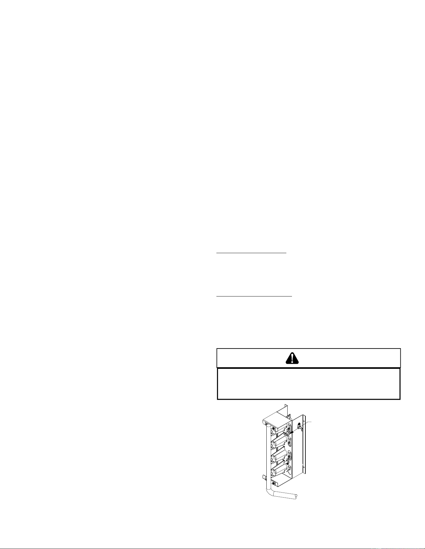
Rollout Protection Control
The rollout protection device opens, cutting power to the gas
valve, if the flames from the burners are not properly drawn
into the heat exchanger. The rollout protection device is located
on the burner bracket. The reason for elevated temperatures
at the control should be determined and repaired prior to
resetting this manual reset control.
WARNING
T
O AVOID PROPERTY DAMAGE, PERSONAL INJURY OR DEATH DUE TO FIRE
OR EXPLOSION, A QUALIFIED SERVICER MUST INVESTIGATE THE REASON FOR
THE ROLLOUT PROTECTION DEVICE TO OPEN BEFORE MANUALLY RESETTING
THE ROLLOUT PROTECTION DEVICE.
Rollout Protectio
n
Rollout Protection on Burner Bracket
15
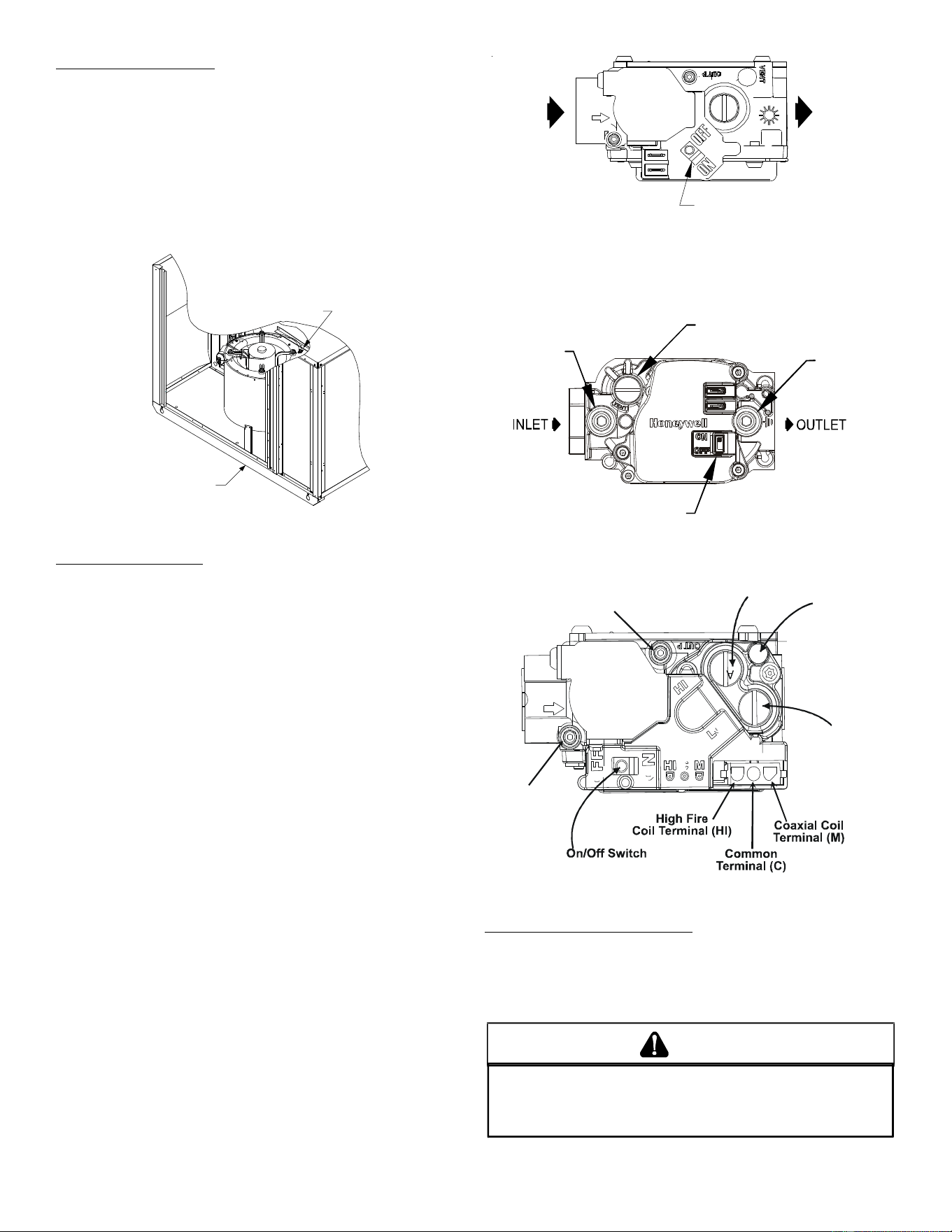
Gas Valve
On/Off
Selector
Switch
I
NLET
OUTLET
White-Rodgers 36G22
Gas Valve On/Off
Selector Switch
I
nlet
P
ressure
T
ap
Pressure Regulator
(under cap screw)
Outlet
Pressure
Tap
Honeywell Model VR8215 (Single-Stage)
Inlet
P
ressure Boss
Low Fire
Regulator Adjust
High Fire Regulator
Adjust
Regulator
Vent
Outlet
Pressure Boss
White-Rodgers Model 36G54
Gas Supply And Manifold Check
Gas supply pressure and manifold pressure with the burners
operating must be as specified on the rating plate.
GAS SUPPLY PRESSURE MEASUREMENT
T
O
PREVENT
UNRELIABLE
OPERATION
OR
EQUIPMENT
DAMAGE
,
THE
I
NLET
GAS
SUPPLY
PRESSURE
MUST
BE
AS
SPECIFIED
ON
THE
UNIT
RATING
PLATE
WITH
ALL
OTHER
HOUSEHOLD
GAS
FIRED
APPLIANCES
OPERATING
.
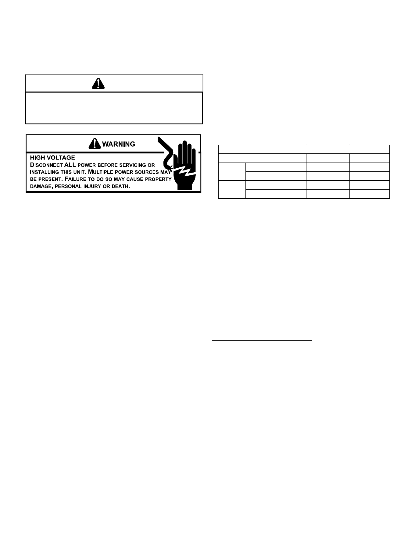
CAUTION
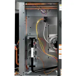
Secondary Limit Control
The secondary limit control is located on the top of the blower
scroll assembly. This control opens when elevated
temperatures are sensed. Elevated temperatures at the
control are normally caused by blower failure. The reason for
the opening should be determined and repaired prior to
resetting.
If the power to the unit is interrupted during the heating cycle,
it may cause the secondary limit to trip. Once the blower
compartment temperature drops below the limit reset
temperature, the limit will automatically reset.
Secondary
Control Limit
Back of Unit
Secondary Limit Control
Pre-Operation Checks
1. Close the manual gas valve external to the unit.
2. Turn off the electrical power supply to the unit.
3. Set the room thermostat to its lowest possible setting.
4. Remove the heat exchanger door on the side of the unit by
removing screws.
5. This unit is equipped with an ignition device which
automatically lights the main burner. DO NOT try to light
burner by any other method.
6. Move the gas control valve switch to the OFF position. Do
not force.
7. Wait five minutes to clear out any gas.
8. Smell for gas, including near the ground. This is important
because some types of gas are heavier than air. If you
have waited five minutes and you do smell gas,
immediately follow the warnings on page 3 of this manual.
If having waited for five minutes and no gas smell is noted,
move the gas control valve switch to the ON position.
9. Replace the heat exchanger door on the side of the unit.
10. Open the manual gas valve external to the unit.
11. Turn on the electrical power supply to the unit.
12. Set the thermostat to desired setting.
16
The line pressure supplied to the gas valve must be within the
range specified in the Inlet Gas Supply Pressure table. The supply
pressure can be measured at the gas valve inlet pressure tap or at
a hose fitting installed in the gas piping drip leg. The supply pres-
sure must be measured with the unit OFF. To measure inlet pres-
sure, use the following procedure.
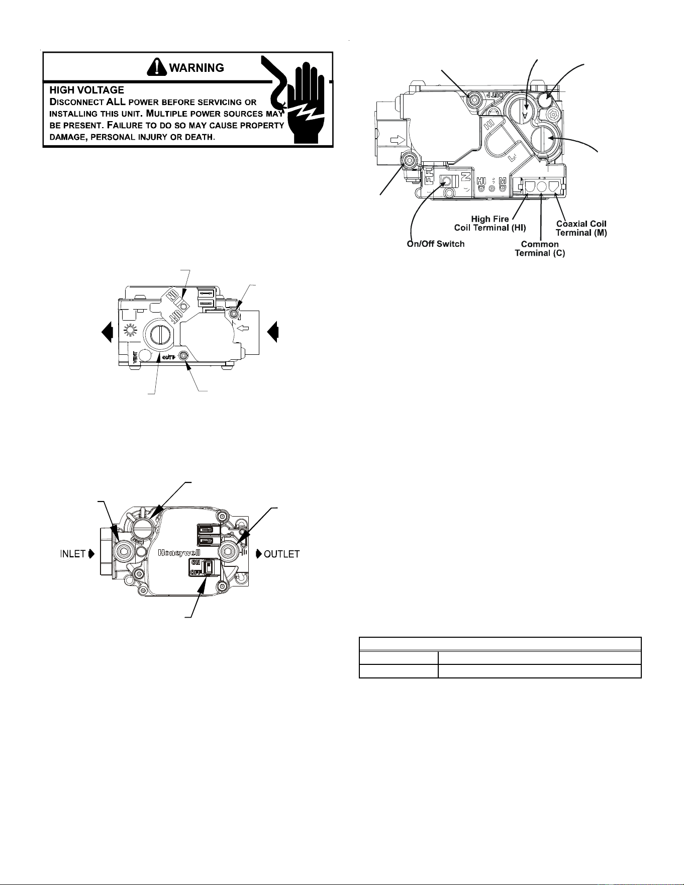
Pressure Regulator
Adjustment
(Under Cap Screw)
Gas Valve
On/Off
Selector
Switch
INLET
O
UTLET
Inlet Pressu
re
Tap
Outlet Pressure
Tap
White-Rodgers Model 36G22
Gas Valve On/Off
Selector Switch
I
nlet
P
ressure
T
ap
Pressure Regulator
(under cap screw)
Outlet
Pressure
Tap
Honeywell Model VR8215 (Single-Stage)
Inlet
P
ressure Boss
Low Fire
Regulator Adjust
High Fire Regulator
Adjust
Regulator
Vent
Outlet
Pressure Boss
White-Rodgers Model 36G54
1. Turn OFF gas to furnace at the manual gas shutoff valve
external to the furnace.
2. Turn OFF all electrical power to the system.
3. Inlet pressure tap connections:
a. Honeywell VR8215 Valve:
Remove the inlet pressure boss plug. Install an 1/8” NPT
hose barb fitting into the outlet pressure tap.
b. White-Rodgers 36G22 or 36G54 valve:
Back inlet pressure test screw (inlet pressure boss) out
one turn (counterclockwise, not more than one turn).
4. Attach a hose and manometer to the outlet pressure barb
fitting (Honeywell valve) or inlet pressure boss (White-
Rodgers valve).
5. Turn ON the gas supply.
6. Turn On power and close thermostat “R” and “W” contacts,
or “R” and “W1” + “W2” for two-stage models, to provide a
call for heat.
7. Using a leak detection solution or soap suds, check for
leaks at outlet pressure boss plug (Honeywell valve) or
screw (White-Rodgers valve). Bubbles forming indicate a
leak. SHUT OFF GAS AND REPAIR ALL LEAKS
IMMEDIATELY!
8. Measure the gas supply pressure with burners firing. Adjust
supply pressure using the Inlet Gas Supply Pressure table
shown below. If supply pressure reading differs from the
table, make necessary adjustments to pressure regulator,
gas piping size, etc., and/or consult with local gas utility.
Propane Gas
Natural Gas
Inlet Gas Supply Pressure
Minimum:5.0" W.C. Maximum :10.0" W.C
.
Minimum:11.0" W.C. Maximum :13.0" W.C
.
9. Turn OFF all electrical power and gas supply to the system.
10.Remove the manometer hose from the hose barb fitting
or inlet pressure boss.
11. Replace inlet pressure tap:
a. Honeywell VR8215 valve:
Remove the 1/8” NPT hose barb fitting from the inlet
pressure tap. Replace the inlet pressure boss plug and
seal with a high quality thread sealer.
b. White-Rodgers 36G22 or 36G54 valve:
Turn inlet pressure test screw in to seal pressure port
(clockwise, 7 in-lb minimum).
17
12.Retest for leaks. If bubbles form, SHUT DOWN GAS AND
REPAIR LEAKS IMMEDIATELY.
13.Turn ON electrical power and gas supply to the system.
14.Turn valve switch ON.
GAS MANIFOLD PRESSURE MEASUREMENT AND ADJUSTMENT
T
O
PREVENT
UNRELIABLE
OPERATION
OR
EQUIPMENT
DAMAGE
,
THE
I
NLET
GAS
SUPPLY
PRESSURE
MUST
BE
AS
SPECIFIED
ON
THE
UNIT
RATING
PLATE
WITH
ALL
OTHER
HOUSEHOLD
GAS
FIRED
APPLIANCES
OPERATING
.
CAUTION
This valve is shipped from the factory with the regulator preset
(see control label).
Consult the appliance rating plate to ensure burner manifold pres-
sure is as specified. If another outlet pressure is required, follow
these steps.
1. Turn OFF gas to furnace at the manual gas shutoff valve
external to the furnace.
2. Turn OFF all electrical power to the system.
3. Outlet pressure tap connections:
a. Honeywell VR8215 valve:
Remove the outlet pressure boss plug. Install an 1/8”
NPT hose barb fitting into the outlet pressure tap.
b. White-Rodgers 36G22 or 36G54 valve:
Back outlet pressure test screw (outlet pressure boss)
out one turn (counterclockwise, not more than one turn).
4. Attach a hose and manometer to the outlet pressure barb
fitting (Honeywell valve) or outlet pressure boss (White-
Rodgers valve).
5. Turn ON the gas supply.
6. Turn ON power and place unit into a heating cycle.
Single Stage Models (Honeywell VR8215 and White-
Rodgers 36G22 valves): Close thermostat “R” and “W”
contacts.
Two-Stage Models (White-Rodgers 36G54 valve): Close
thermostat contacts “R” and “W1” contacts for low heat
stage heating ONLY; do not energize high stage heat.
7. Using a leak detection solution or soap suds, check for
leaks at outlet pressure boss plug (Honeywell valve) or
screw (White-Rodgers valve). Bubbles forming indicate a
leak. SHUT OFF GAS AND REPAIR ALL LEAKS
IMMEDIATELY!
8. Measure the gas manifold pressure with burners firing.
Adjust manifold pressure using the Manifold Gas Pressure
table shown below.
9. Regulator adjustment:
Single Stage Models (Honeywell VR8215 and White-
Rodgers 36G22 valves):
Remove regulator cover screw from the outlet pressure
regulator and turn screw clockwise to increase pressure
or counterclockwise to decrease pressure. Replace
regulator cover screw.
Two-Stage Models (White-Rodgers 36G54 valve):
Remove regulator cover screw from the low (LO) outlet
pressure regulator adjust tower and turn screw clockwise
to increase pressure, or counterclockwise to decrease
pressure.
Entergize the “R”, “W1”, and “W2” contacts for high stage
heat. Remove regulator cover screw from the HI outlet
pressure regulator adjust tower and turn screw clockwise
to increase pressure or counterclockwise to decrease
pressure.
Range Nominal
Low Stage 1.6 - 2.2" w.c. 2.0" w.c.
High or Single Stage 3.2 - 3.8" w.c. 3.5" w.c.
Low Stage 5.7 - 6.3" w.c. 6.0" w.c.
High or Single Stage 9.7 - 10.3" w.c. 10.0" w.c.
Manifold Gas Pressure
Gas
Natural
LP
10.Turn OFF all electrical power and gas supply to the system.
11. Remove the manometer hose from the hose barb fitting
or outlet pressure boss.
12.Replace outlet pressure tap:
a. Honeywell VR8215 valve:
Remove the 1/8” NPT hose barb fitting from the outlet
pressure tap. Replace the outlet pressure boss plug and
seal with a high quality thread sealer.
b. White-Rodgers 36G22 or 36G54 valve: Turn outlet
pressure test screw in to seal pressure port (clockwise,
7 in-lb minimum).
13.Turn ON electrical power and gas supply to the system.
14.Close thermostat contacts to provide a call for heat.
15.Retest for leaks. If bubbles form, SHUT OFF GAS AND
REPAIR ALL LEAKS IMMEDIATELY!
Gas Input (Natural Gas Only) Check
To measure the gas input use a gas meter and proceed as
follows:
1. Turn off gas supply to all other appliances except the unit.
2. With the unit operating, time the smallest dial on the meter
for one complete revolution. If this is a 2 cubic foot dial,
divide the seconds by 2; if it is a 1 cubic foot dial, use the
seconds as is. This gives the seconds per cubic foot of
gas being delivered to the unit.
3. INPUT=GAS HTG VALUE x 3600 / SEC. PER CUBIC FOOT
Example: Natural gas with a heating value of 1000 BTU per cubic
foot and 34 seconds per cubic foot as determined by Step 2, then:
Input = 1000 x 3600 / 34 = 106,000 BTU per Hour. NOTE:
BTU content of the gas should be obtained from the gas
supplier. This measured input must not be greater than
shown on the unit rating plate.
4. Relight all other appliances turned off in step 1. Be sure all
pilot burners are operating.
Main Burner Flame Check
Flames should be stable, soft and blue (dust may cause
orange tips but they must not be yellow) and extending directly
outward from the burner without curling, floating or lifting off.
18
Temperature Rise Check
Check the temperature rise through the unit by placing
thermometers in supply and return air registers as close to
the unit as possible. Thermometers must not be able to
sample temperature directly from the unit heat exchangers,
or false readings could be obtained.
1. All registers must be open; all duct dampers must be in
their final (fully or partially open) position and the unit
operated for 15 minutes before taking readings.
2. The temperature rise must be within the range specified
on the rating plate.
NOTE: Air temperature rise is the temperature difference between
supply and return air.
With a properly designed system, the proper amount of
temperature rise will normally be obtained when the unit is
operated at rated input with the recommended blower speed.
If the correct amount of temperature rise is not obtained, it
may be necessary to change the blower speed. A higher
blower speed will lower the temperature rise. A slower blower
speed will increase the temperature rise.
NOTE: Blower speed MUST be set to give the correct air tempera-
ture rise through the unit as marked on the rating plate.
External Static Pressure Check
The total external static pressure must be checked on this
unit to determine if the airflow is proper.
Blower Speed Adjustments
WARNING
T
O AVOID PERSONAL INJURY OR DEATH DUE TO ELECTRIC SHOCK, REMOVE
ELECTRICAL POWER FROM THE UNIT BEFORE CHANGING SPEED TAPS ON THE
BLOWER MOTOR.
Refer to the wiring diagram in the appendix to verify speed tap
settings.
All models are equipped with EEM motors. EEM motors are
constant torque motors with very low power consumption.
This motor is energized by 24V. Adjust the CFM for the unit by
changing the 24V low voltage leads to the speed terminal
block on the motor.
Single Stage Models:
Heating-White Lead Cooling-Yellow Lead
T1 - Low Speed T4 - Low Speed
T2 - Medium Speed T5 - High Speed
T3 - High Speed
Two-Stage Models:
Speed
Tap
Definition
Lead
Color
Speed
Tap
Definition
Lead
Color
T1
Low
Speed Heat
White T3
Low Speed
Cool
Purple
T2
High
Speed Heat
Brown T4
High Speed
Cool
Yellow
T5
High Speed
Cool Hi-Static
HEATING COOLING
NOTE: Heating airflow must be adjusted to provide the tempera-
ture rise shown on rating plate.
Limit Check
Check limit control operation after 15 minutes of operation
by blocking the return air grille(s).
1. After several minutes the main burners must go OFF.
Blower will continue to run.
2. Remove air restrictions and main burners will relight
after a cool down period of a few minutes.
Adjust the thermostat setting below room temperature.
1. Main burners must go OFF.
2. Circulating Air Blower will continue to run for 120, 135 or
150 seconds, (single stage models) or 90, 120, 150, or
180 seconds (two-stage models), depending on the
setting.
1
2
3
10
11
12
9
6
23
6
5
8
9
11
12
L2
L2L2
L2
D1 L1
L1 UNUSED HEAT
COOL
FS
K2
K1
R8
R10
R3
K4
K3
R31
LED
1
0
6
8
-
8
3
-
4
0
0
A
C27
D3
R38
D9
D10
R34
R35
R4
R11
R42
D12
R36
D11
D14
C20
Z
1
R29
R22
C13
R25
D5
D7
Control Board (Single Stage)
LO CO OL
HI COOL
LO HE AT
HI HEAT
U6
U7
U4
U5
U3
K2
K1
P1
ECON
STAGE
DEL AY
SPEEDUP
SW1
FAULT
RECA L L
BL OWER
OFF DEL A Y
F1
RCW1W2
GY1Y2
Control Board (Two-Stage)
NOTE: If necessary, adjust fan OFF delay settings to obtain satis-
factory comfort level.
Unit Shutdown
1. Set the thermostat to lowest setting.
2. Turn off the electrical power supply to the unit.
3. Remove the heat exchanger door on the side of the unit by
removing screws.
4. Move the gas control valve switch to the OFF position. Do
not force.
5. Close manual gas shutoff valve external to the unit.
6. Replace the heat exchanger door on the unit.
7. If cooling and/or air circulation will be desired, turn ON the
electrical power.
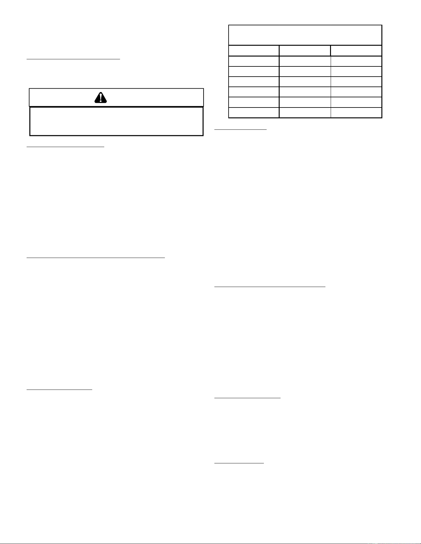
19
COOLING S TARTUP
NOTE: Check all manual reset limit controls in heating circuit if
cooling mode does not operate.
Compressor Protection Devices
The compressor includes components which are designed
to protect the compressor against abnormal operating
conditions.
WARNING
T
O PREVENT PERSONAL INJURY OR DEATH, ALWAYS DISCONNECT ELECTRICA
L
POWER BEFORE INSPECTING OR SERVICING THE UNIT.
A
LL COMPRESSOR
PROTECTION DEVICES RESET AUTOMATICALLY, ENERGIZING THE CONTACTOR
AND OUTDOOR FAN.
Refrigerant Charge Check
After completing airflow measurements and adjustments the
unit’s refrigerant charge must be checked. The unit comes
factory charged, but this charge is based on 325 CFM per ton
and minimum ESP per AHRI test conditions (generally
between .15 -.28 ESP). When air quantity or ESP is different
than above, the refrigerant charge must be adjusted to the
proper amount. All package units with fixed orifice devices
are charged using the super heat method at the compressor
suction line.
After superheat is adjusted it is recommended to check unit
sub-cooling at the condenser coil liquid line out. For charge
adjustments, see superheat and sub-cooling charts shown
for each model.
Cooling Refrigerant Charging (Models with TXV)
Check unit charge before putting the cooling section into full
operation. The unit has a thermostatic expansion valve
metering device. To ensure the unit is properly charged for
the intended application, check the unit refrigerant sub-
cooling at the condenser. The refrigerant sub-cooling is a
function of outdoor ambient temperature and return air
temperature of the conditioned space. It is the installing
contractors responsibility to ensure the proper refrigerant
sub-cooling at the condenser is adjusted for each application.
As the outdoor ambient temperature rises the sub-cooling
decreases and as the outdoor ambient temperature lowers,
the sub-cooling increases. NOTE: Proper sub-cooling
adjustment optimizes cooling performance. Models equipped
with thermostatic expansion valve, charge the system to sub-
cooling, range shown on chart, when necessary, adjust
expansion valve stem for superheat setting.
Superheat Adjustment
To adjust superheat, remove the control box cover and locate
the expansion valve on the liquid line of the evaporator.
Unscrew the cover from the expansion valve, locate the
adjustment screw, and turn it clockwise (in) to increase
superheat or counterclockwise (out) to decrease superheat.
Replace adjustment cap. Wait a minimum of 10 minutes
between adjustments to allow time for the TXV and pressures
to stabilize.
NOTE: The expansion valve will not need adjustment for most
applications. Ensure system superheat is set within range listed
on chart.
Models # Superheat ± 2°F Subcooling ± 3°F
*PG1424***M
12 11
*PG1430***M
515
*PG1436***M
611
*PG1442***M
10 12
*PG1448***M
412
*PG1461***M
11 11
Design superheat & subcooling @ 95 °F
outdoor ambient temperature
Cooling Operation
NOTE: Mechanical cooling cannot be reliably provided at ambient
temperatures below 50° F.
1. Turn on the electrical power supply to the unit.
2. Place the room thermostat selector switch in the COOL
position (or AUTO if available, and if automatic changeover
from cooling to heating is desired).
3. Set the room thermostat to the desired temperature.
TROUBLESHOOTING
IGNITION CONTROL ERROR CODES
The following presents probable causes of questionable unit
operation. Refer to Diagnostic Indicator Chart for an
interpretation of the signal and to this section for an explanation.
Remove the control box access panel and note the number of
diagnostic LED flashes. Refer to Diagnostic Indicator Chart
for an interpretation of the signal and to this section for an
explanation.
Fault Recall (Two-Stage Models ONLY)
The ignition control is equipped with a momentary push-button
switch that can be used to display on the diagnostic LED the
last five faults detected by the control. The control must be in
Standby Mode (no thermostat inputs) to use the feature.
Depress the push-button switch for approximately 2 seconds.
NOTE: Do not hold for longer than 4 seconds. Holding the
button for 4 seconds or higher will erase the memory!
Release the switch when the LED is turned off. The diagnostic
LED will then display the flash codes associated with the last
five detected faults. The order of display is the most recent
fault to the least recent fault.
ABNORMAL OPERATION - HEATING
Internal Control Failure
If the integrated ignition control in this unit encounters an
internal fault, it will go into a “hard” lockout and turn off the
diagnostic LED. If diagnostic LED indicates an internal fault,
check power supply to unit for proper voltage, check all fuses,
circuit breakers and wiring. Disconnect electric power for five
seconds. If LED remains off after restoring power, replace
control.
External Lockout
An external lockout occurs if the integrated ignition control
determines that a measurable combustion cannot be
established within three (3) consecutive ignition attempts. If
flame is not established within the seven (7) second trial for
ignition, the gas valve is de-energized, 15 second inter-purge

20
cycle is completed, and ignition is reattempted. The control
will repeat this routine three times if a measurable combustion
is not established. The control will then shut off the induced
draft blower and go into a lockout state.
If flame is established but lost, the control will energize the
circulator blower at the heat speed and then begin a new
ignition sequence. If flame is established then lost on
subsequent attempts, the control will recycle for four (4)
consecutive ignition attempts (five attempts total) before
locking out.
The diagnostic fault code is 1 flash for a lockout due to failed
ignition attempts or flame dropouts. The integrated control
will automatically reset after one hour, or it can be reset by
removing the thermostat signal or disconnecting the electrical
power supply for over five seconds. If the diagnostic LED
indicates an external lockout, perform the following checks:
• Check the supply and manifold pressures
• Check the gas orifices for debris
• Check gas valve for proper operation
• Check secondary limit
A dirty filter, excessive duct static, insufficient air flow, a
faulty limit, or a failed circulator blower can cause this
limit to open. Check filters, total external duct static,
circulator blower motor, blower motor speed tap (see
wiring diagram), and limit. An interruption in electrical
power during a heating cycle may also cause the
auxiliary limit to open. The automatic reset secondary
limit is located on top of the circulator blower assembly.
• Check rollout limit
If the burner flames are not properly drawn into the
heat exchanger, the flame rollout protection device will
open. Possible causes are restricted or blocked flue
passages, blocked or cracked heat exchanger, a failed
induced draft blower, or insufficient combustion air. The
rollout protection device is a manual reset limit located
on the burner bracket. The cause of the flame rollout
must be determined and corrected before resetting
the limit.
• Check flame sensor
A drop in flame signal can be caused by nearly invisible
coating on the sensor. Remove the sensor and carefully
clean with steel wool.
• Check wiring
Check wiring for opens/shorts and miswiring.
Important: If you have to frequently reset your gas/electric
package unit, it means that a problem exists that should
be corrected. Contact a qualified servicer for further
information.
Pressure Switch Stuck Open
A pressure switch stuck open can be caused by a faulty
pressure switch, faulty wiring, a disconnected or damaged
hose, a blocked or restricted flue, or a faulty induced draft
blower.
If the control senses an open pressure switch during the pre-
purge cycle, the induced draft blower only will be energized. If
the pressure switch opens after ignition has begun the gas
valve is de-energized, the circulator blower heat off cycle
begins, and the induced draft blower remains on. The
diagnostic fault code is two flashes.
Pressure Switch Stuck Closed
A stuck closed pressure switch can be caused by a faulty
pressure switch or faulty wiring. If the control encounters a
pressure switch stuck closed, the induced draft blower
remains off. The diagnostic LED code for this fault is three (3)
flashes.
Open Thermal Protection Device
If the primary limit switch opens, the gas valve is immediately
de-energized, the induced draft and air circulating blowers
are energized. The induced draft and air circulator blowers
remain energized until the limit switch recloses. The
diagnostic fault code for an open limit is four (4) flashes.
A primary limit will open due to excessive supply air
temperatures. This can be caused by a dirty filter, excessive
duct static, insufficient air flow, or a faulty limit. Check filters,
total external duct static, blower motor, blower motor speed
tap (see wiring diagram), and limit. This limit will automatically
reset once the temperature falls below a preset level.
Primary Limit
A primary limit will open due to excessive supply air
temperatures. This can be caused by a dirty filter, excessive
duct static, insufficient air flow, or a faulty limit. Check filters,
total external duct static, blower motor, blower motor speed
tap (see wiring diagram), and limit. This limit will automatically
reset once the temperature falls below a preset level.
Auxiliary/Secondary Limit
A dirty filter, excessive duct static, insufficient air flow, a faulty
limit, or a failed circulator blower can cause this limit to open.
Check filters, total external duct static, circulator blower motor,
blower motor speed tap (see wiring diagram), and limit. An
interruption in electrical power during a heating cycle may
also cause the auxiliary limit to open. The automatic reset
secondary limit is located on top of the circulator blower
assembly.
Rollout Limit
If the burner flames are not properly drawn into the heat
exchanger, the flame rollout protection device will open.
Possible causes are restricted or blocked flue passages,
blocked or cracked heat exchanger, a failed induced draft
blower, or insufficient combustion air. The rollout protection
device is a manual reset limit located on the burner bracket.
The cause of the flame rollout must be determined and
corrected before resetting the limit.
Flame Detected with Gas Valve Closed
If flame is detected with the gas valve de-energized, the
combustion and air circulator blowers are energized. The
diagnostic fault code is five (5) flashes for this condition. The
control can be reset by removing the power supply to the unit
or it will automatically reset after one hour. Miswiring is the
probable cause for this fault.
Low Flame Signal (Two-Stage Models ONLY)
Under some conditions, the fuel or air supply can create a
nearly invisible coating on the flame sensor. This coating acts
as an insulator causing a drop in the flame signal. If the flame
signal drops below a predetermined value, the ignition control
will display an error code of (1) flash on the amber diagnostic
LED. The unit will continue to operate until the control can no
longer detect flame.
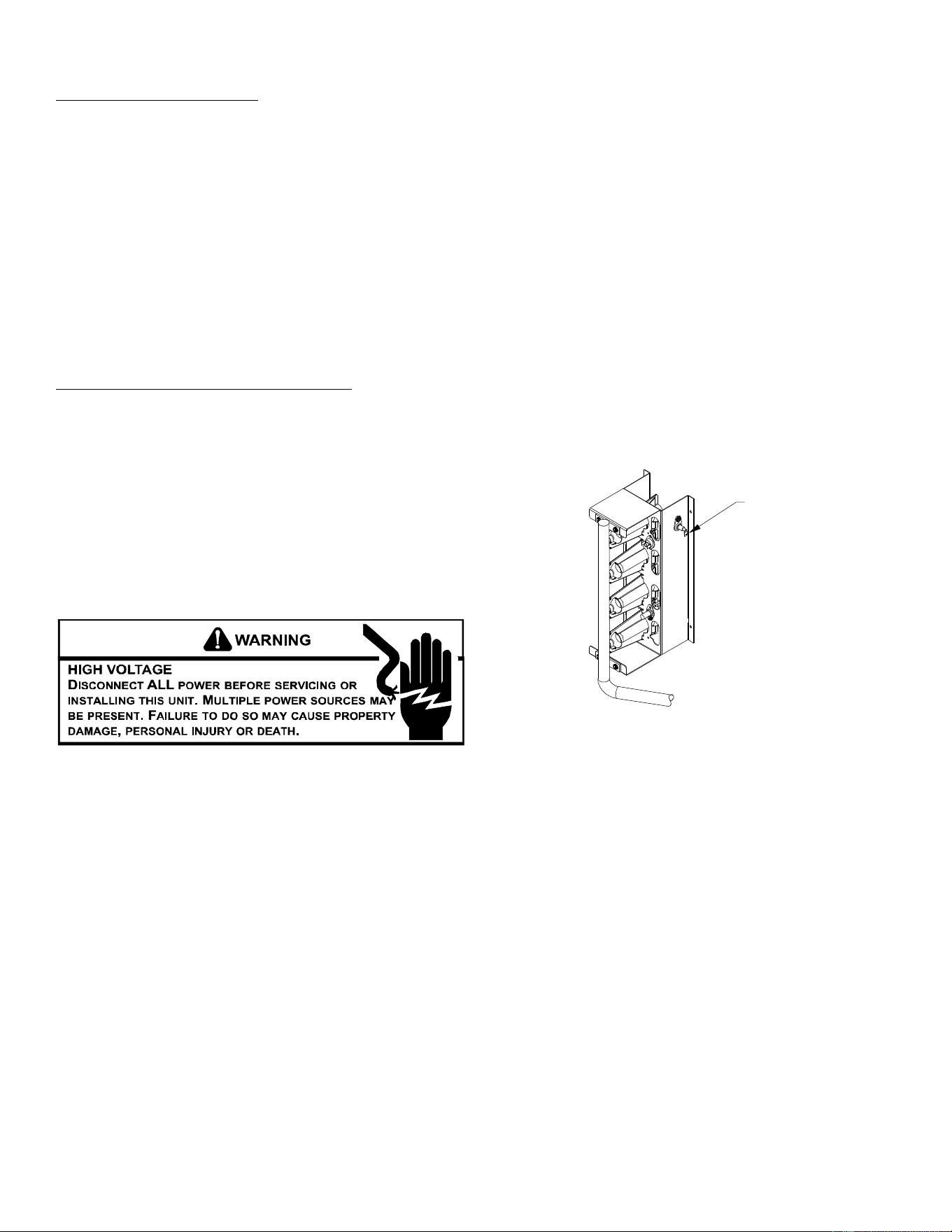
21
ABNORMAL OPERATION - COOLING
Short Cycle Compressor Delay
The automatic ignition control has a built-in feature that
prevents damage to the compressor in short cycling
situations. In the event of intermittent power losses or
intermittent thermostat operation, the ignition control will delay
output to the compressor contactor for three minutes from the
time power is restored. (Compressor is off a total of three
minutes). The diagnostic LED will flash six (6) times to indicate
the compressor contactor output is being delayed.
NOTE: Some electronic thermostats also have a built-in compressor
short cycle timer that may be longer than the three minute delay
given above. If you are using an electronic thermostat and the
compressor has not started after three minutes, wait an additional
five minutes to allow the thermostat to complete its short cycle
delay time.
High Pressure Switch/Loss of Charge Switch
(Two-Stage Models ONLY)
Some models include a high pressure cutout switch and/or a
loss of charge cutout switch. The high pressure cutout switch
protects the refrigeration system from excessive operating
pressures. The loss of charge cutout switch protects the
refrigeration system from very low operating pressures due
to a loss of refrigerant. Compressor operation will be disabled
if either of these devices opens. If either device opens, the
diagnostic red LED will flash (9) times to indicate that a
refrigeration system pressure switch is open.
MAINTENANCE
Have the gas heating section of the unit checked at least
once a year before the heating season begins, to be sure that
the combustion air inlet and flue outlet hoods are not blocked
by debris, which would prevent adequate combustion air and
a properly operating vent system.
FILTER REPLACEMENT OR CLEANING
A return air filter is not supplied with this unit; however, there
must be a means of filtering all of the return air. The filter(s)
may be located in the return air duct(s), or return air filter
grille(s). Consult with your installing dealer for the actual
location of the return air filter(s) for your unit.
Dirty filters are the most common cause of inadequate heating
or cooling performance. Filter inspection should be made at
least every two months; more often if necessary because of
local conditions and usage.
Dirty throwaway filters should be discarded and replaced with
a new, clean filter. Dirty permanent filters should be washed
with water, thoroughly dried and sprayed with a filter adhesive
before being reinstalled. (Filter adhesives may be found at
many hardware stores.) Permanent filters should last several
years. However, should one become torn or uncleanable, it
should be replaced.
CABINET F INISH M AINTENANCE
Use a fine grade automotive wax on the cabinet finish to
maintain the finish’s original high luster. This is especially
important in installations with extended periods of direct
sunlight.
CLEAN OUTSIDE COIL (QUALIFIED SERVICER ONLY)
The coil with the outside air flowing over it should be inspected
annually and cleaned as frequently as necessary to keep the
finned areas free of lint, hair and debris.
CONDENSER, EVAPORATOR, AND INDUCED DRAFT MOTORS
Bearings on the air circulating blower motor, condenser motor
and the combustion fan motor are permanently lubricated.
No additional oiling is required.
FLAME SENSOR (QUALIFIED SERVICER ONLY)
A drop in the flame current can be caused by a nearly invisible
coating on the flame sensor. This coating, created by the fuel
or combustion air supply, can be removed by carefully cleaning
the flame sensor with steel wool.
NOTE: After cleaning, the microamp signal should be stable and in
the range of 4 - 6 microamps DC.
Flame
Sens
or
Flame Sensor
FLUE PASSAGES (QUALIFIED SERVICER ONLY)
At the start of each heating season, inspect and, if necessary,
clean the unit flue passage.
CLEANING FLUE PASSAGES (QUALIFIED SERVICER ONLY)
1. Shut off electric power and gas supply to the unit.
2. Remove burner assembly by disconnecting the gas line
and removing the manifold bracket from the partition panel.
3. Remove the flue from the induced draft blower and the
collector box cover from the partition panel.
4. The primary heat exchanger tubes can be cleaned using
a round wire brush attached to a length of high grade
stainless steel cable, such as drain cleanout cable. Attach
a variable speed reversible drill to the other end of the
spring cable. Slowly rotate the cable with the drill and insert
it into one of the primary heat exchanger tubes. While
reversing the drill, work the cable in and out several times
to obtain sufficient cleaning. Use a large cable for the large
tube, and then repeat the operation with a small cable for
the smaller tube. Repeat for each tube.
5. When all heat exchanger tubes have been cleaned,
replace the parts in the reverse order in which they were
removed.
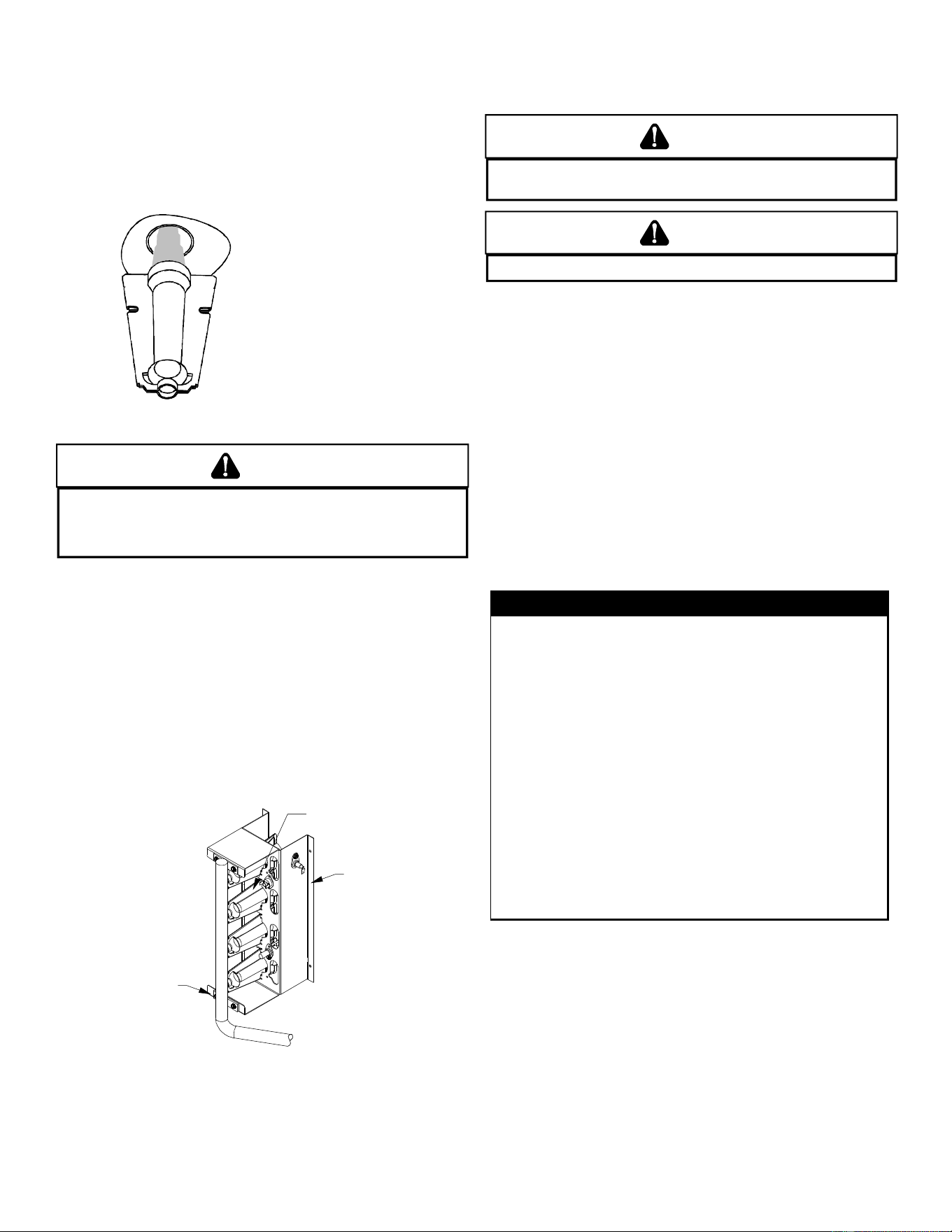
22
6. To reduce the chances of repeated fouling of the heat
exchanger, perform the steps listed in “Startup,
Adjustments, and Checks”.
MAIN BURNER FLAME (QUALIFIED SERVICER ONLY)
Flames should be stable, soft and blue (dust may cause
orange tips but must not be yellow). The flames must extend
directly outward from the burner without curling, floating or
lifting off.
Check the burner flames for:
1. Good adjustment
2. Stable, soft and blue
3. Not curling, floating, or lifting of
f.
Burner Flame
WARNING
T
O AVOID PERSONAL INJURY OR DEATH DUE TO ELECTRIC SHOCK,
DO NOT REMOVE ANY INTERNAL COMPARTMENT COVERS OR ATTEMPT ANY
ADJUSTMENT.
C
ONTACT A QUALIFIED SERVICER AT ONCE IF AN ABNORMAL
FLAME SHOULD DEVELOP.
At least once a year, prior to or during the heating season,
make a visual check of the burner flames.
NOTE: This will involve removing and reinstalling the heat exchanger
door on the unit, which is held by two screws. If you are uncertain
about your ability to do this, contact a qualified servicer.
If a strong wind is blowing, it may alter the airflow pattern within the
unit enough that an inspection of the burner flames is not pos-
sible.
CLEANING B URNERS
1. Shut off electric power and gas supply to the unit.
2. Remove the screws securing the manifold to the burner
retention bracket. Remove the manifold and rotate each
burner counterclockwise to remove.
Burne
r
Brack
et
Burner
M
anifold
Manifold Assembly
3. Remove the burners.
4. Use a bottle brush to clean burner insert and inside of the
burners.
5. Replace burners and manifold, inspect the burner
assembly for proper seating of burners in retention slots.
6. Reconnect electrical power and gas supply.
CAUTION
L
ABEL ALL WIRES PRIOR TO DISCONNECTION WHEN SERVICING CONTROLS.
W
IRING ERRORS CAN CAUSE IMPROPER AND DANGEROUS OPERATION.
CAUTION
A
LWAYS VERIFY PROPER OPERATION AFTER SERVICING.
For further information on the yearly inspection, consult the
User Manual. It is recommended that a qualified servicer
inspect and service the unit at least once each year.
Turn the unit on at the thermostat. Wait a few minutes, since
any dislodged dust will alter the normal flame appearance.
Flames should be predominantly blue and directed into the
tubes. They should not be yellow. They should extend directly
outward from the burner ports without curling downward,
floating or lifting off the ports.
ACCESSORIES AND FUNCTIONAL PARTS
SHEET METAL A CCESSORIES
Additional accessories can be purchased to fit specific application
needs. Parts and instructions are available from your distributor.
FUNCTIONAL P ARTS
Auxiliary Limit Switch Flame Roll-out Switch
Blower Housing Flame Sensor
Circulator Blower Motor Gas Orifice
Blower Wheel Gas Valve
Burner Heat Exchanger
Capacitor High Limit Switch
Compressor Igniter
Condenser Coil Ignition Control
Condenser Fan Blade Induced Draft Blower
Condenser Fan Motor Pressure Switch
Contactor Pressure Switch Hose
Gas Manifold Thermostatic Expansion Valve
Evaporator Coil Transformer
FUNCTIONAL PARTS
Functional Parts List
GENERAL I NFORMATION
1. Refer to the description in Functional Parts List when
ordering any of the listed functional parts. Be sure to provide
the unit model and serial numbers with the order.
2. Although only functional parts are shown, all sheet metal
parts, doors, etc. may be ordered by description.
3. Parts are available from your distributor.
23
BLOWER PERFORMANCE DATA - SINGLE PHASE
X= Heating Temperature Rise Not Recommended.
NOTE: The shaded area indicates ranges in excess of maximum external static pressure allowable when heating. For satisfactory operation,
external static pressure should not exceed 0.5" w.c.
CFMWATTSRISE CFMWATTSRISE CFMWATTSRISE CFMWATTSCFMWATTS
0.1 695 62 44 820 93 37 1,050 167 29 850 100 1,095 198
0.2 650 71 47 785 100 39 1,010 180 30 800 106 1,060 202
0.3 605 77 51 745 108 41 970 186 32 765 116 1,025 214
0.4 565 89 54 700 117 44 935 192 33 730 125 985 217
0.5 480 99 X 665 127 46 890 203 35 680 131 945 227
0.6 415 106 X 575 138 53 850 208 36 610 141 905 233
0.7 365 110 X 510 146 X 815 216 38 550 153 865 237
0.8 320 119 X 455 155 X 755 222 41 490 159 825 246
CFMWATTSRISE CFMWATTSRISE CFMWATTSRISE CFMWATTSCFMWATTS
0.1 695 62 X 820 93 56 1,050 167 44 850 100 1,095 198
0.2 650 71 X 785 100 59 1,010 180 46 800 106 1,060 202
0.3 605 77 X 745 108 X 970 186 48 765 116 1,025 214
0.4 565 89 X 700 117 X 935 192 49 730 125 985 217
0.5 480 99 X 665 127 X 890 203 52 680 131 945 227
0.6 415 106 X 575 138 X 850 208 54 610 141 905 233
0.7 365 110 X 510 146 X 815 216 57 550 153 865 237
0.8 320 119 X 455 155 X 755 222 X 490 159 825 246
CFMWATTSRISE CFMWATTSRISE CFMWATTSRISE CFMWATTSCFMWATTS
0.1 680 61 45 840 103 37 1,035 174 30 1,035 174 1,225 276
0.2 640 72 48 795 109 39 995 184 31 995 184 1,185 275
0.3 605 80 51 750 117 41 960 192 32 960 192 1,150 289
0.4 555 89 X 710 126 43 925 205 33 925 205 1,115 296
0.5 490 93 X 660 132 47 875 200 35 875 200 1,085 303
0.6 455 107 X 615 138 50 840 217 37 840 217 1,045 312
0.7 395 109 X 570 150 54 795 222 39 795 222 1,000 315
0.8 350 119 X 515 157 X 755 226 41 755 226 960 320
CFMWATTSRISE CFMWATTSRISE CFMWATTSRISE CFMWATTSCFMWATTS
0.1 680 61 X 840 103 55 1,035 174 45 1,035 174 1,225 276
0.2 640 72 X 795 109 58 995 184 46 995 184 1,185 275
0.3 605 80 X 750 117 X 960 192 48 960 192 1,150 289
0.4 555 89 X 710 126 X 925 205 50 925 205 1,115 296
0.5 490 93 X 660 132 X 875 200 53 875 200 1,085 303
0.6 455 107 X 615 138 X 840 217 55 840 217 1,045 312
0.7 395 109 X 570 150 X 795 222 58 795 222 1,000 315
0.8 350 119 X 515 157 X 755 226 X 755 226 960 320
*PG1424040M41** - Rise Range: 25° - 55°
E.S.P.
T1 HEATING SPEED T2 HEATING SPEED T3 HEATING SPEED
T4 COOLING
SPEED
T5 COOLING
SPEED
*PG1424060M41** - Rise Range: 30° - 60°
E.S.P.
T1 HEATING SPEED T2 HEATING SPEED T3 HEATING SPEED
T4 COOLING
SPEED
T5 COOLING
SPEED
*PG1430040M41** - Rise Range: 25° - 55°
E.S.P.
T1 HEATING SPEED T2 HEATING SPEED T3 HEATING SPEED
T4 COOLING
SPEED
T5 COOLING
SPEED
*PG1430060M41** - Rise Range: 30° - 60°
E.S.P.
T1 HEATING SPEED T2 HEATING SPEED T3 HEATING SPEED
T4 COOLING
SPEED
T5 COOLING
SPEED
24
BLOWER PERFORMANCE DATA - SINGLE PHASE
X = Heating Temperature Rise Not Recommended.
NOTE: The shaded area indicates ranges in excess of maximum external static pressure allowable when heating. For satisfactory operation,
external static pressure should not exceed 0.5" w.c.
CFM WATTS RISE CFM WATTS RISE CFM WATTS RISE CFM WATTS CFM WATTS
0.1 745 76 41 1,115 206 28 1,265 285 X 1,305 311 1,440 426
0.2 690 84 45 1,075 215 29 1,230 290 X 1,265 320 1,390 428
0.3 635 91 48 1,030 221 30 1,175 300 26 1,225 325 1,365 440
0.4 570 98 54 985 233 31 1,140 303 27 1,180 334 1,335 440
0.5 505 107 X 940 234 33 1,100 311 28 1,140 338 1,295 456
0.6 450 115 X 895 242 34 1,055 319 29 1,095 349 1,255 456
0.7 395 118 X 845 248 36 1,010 326 30 1,050 350 1,220 465
0.8 345 126 X 785 252 39 960 335 32 1,010 357 1,180 468
CFM WATTS RISE CFM WATTS RISE CFM WATTS RISE CFM WATTS CFM WATTS
0.1 745 76 X 1,115 206 41 1,265 285 36 1,305 311 1,440 426
0.2 690 84 X 1,075 215 43 1,230 290 37 1,265 320 1,390 428
0.3 635 91 X 1,030 221 45 1,175 300 39 1,225 325 1,365 440
0.4 570 98 X 985 233 47 1,140 303 40 1,180 334 1,335 440
0.5 505 107 X 940 234 49 1,100 311 42 1,140 338 1,295 456
0.6 450 115 X 895 242 52 1,055 319 44 1,095 349 1,255 456
0.7 395 118 X 845 248 55 1,010 326 46 1,050 350 1,220 465
0.8 345 126 X 785 252 59 960 335 48 1,010 357 1,180 468
CFM WATTS RISE CFM WATTS RISE CFM WATTS RISE CFM WATTS CFM WATTS
0.1 745 76 X 1,115 206 55 1,265 285 49 1,305 311 1,440 426
0.2 690 84 X 1,075 215 57 1,230 290 50 1,265 320 1,390 428
0.3 635 91 X 1,030 221 60 1,175 300 52 1,225 325 1,365 440
0.4 570 98 X 985 233 X 1,140 303 54 1,180 334 1,335 440
0.5 505 107 X 940 234 X 1,100 311 56 1,140 338 1,295 456
0.6 450 115 X 895 242 X 1,055 319 58 1,095 349 1,255 456
0.7 395 118 X 845 248 X 1,010 326 X 1,050 350 1,220 465
0.8 345 126 X 785 252 X 960 335 X 1,010 357 1,180 468
CFM WATTS RISE CFM WATTS RISE CFM WATTS RISE CFM WATTS CFM WATTS
0.1 830 99 56 1,185 228 39 1,335 317 35 1,335 320 1,630 556
0.2 785 106 59 1,140 232 40 1,300 325 35 1,305 331 1,595 561
0.3 730 116 X 1,100 247 42 1,265 331 36 1,265 343 1,555 566
0.4 675 122 X 1,060 253 44 1,215 338 38 1,225 343 1,520 571
0.5 630 129 X 1,020 258 45 1,170 346 39 1,190 343 1,485 568
0.6 575 138 X 975 267 47 1,135 351 41 1,135 351 1,450 576
0.7 520 144 X 900 274 51 1,085 354 42 1,095 358 1,410 579
0.8 440 150 X 855 282 54 1,025 361 45 1,040 367 1,370 590
CFM WATTS RISE CFM WATTS RISE CFM WATTS RISE CFM WATTS CFM WATTS
0.1 830 99 X 1,185 228 52 1,335 317 46 1,335 320 1,630 556
0.2 785 106 X 1,140 232 54 1,300 325 47 1,305 331 1,595 561
0.3 730 116 X 1,100 247 56 1,265 331 49 1,265 343 1,555 566
0.4 675 122 X 1,060 253 58 1,215 338 51 1,225 343 1,520 571
0.5 630 129 X 1,020 258 X 1,170 346 53 1,190 343 1,485 568
0.6 575 138 X 975 267 X 1,135 351 54 1,135 351 1,450 576
0.7 520 144 X 900 274 X 1,085 354 57 1,095 358 1,410 579
0.8 440 150 X 855 282 X 1,025 361 60 1,040 367 1,370 590
*PG1436040M41** - Rise Range: 25° - 55°
E.S.P.
T1 HEATING SPEED T2 HEATING SPEED T3 HEATING SPEED
T4 COOLING
SPEED
T5 COOLING
SPEED
*PG1436060M41** - Rise Range: 30° - 60°
E.S.P.
T1 HEATING SPEED T2 HEATING SPEED T3 HEATING SPEED
T4 COOLING
SPEED
T5 COOLING
SPEED
*PG1436080M41** - Rise Range: 30° - 60°
E.S.P.
T1 HEATING SPEED T2 HEATING SPEED T3 HEATING SPEED
T4 COOLING
SPEED
T5 COOLING
SPEED
*PG1442060M41** - Rise Range: 30° - 60°
E.S.P.
T1 HEATING SPEED T2 HEATING SPEED T3 HEATING SPEED
T4 COOLING
SPEED
T5 COOLING
SPEED
*PG1442080M41** - Rise Range: 30° - 60°
E.S.P.
T1 HEATING SPEED T2 HEATING SPEED T3 HEATING SPEED
T4 COOLING
SPEED
T5 COOLING
SPEED
25
BLOWER PERFORMANCE DATA - SINGLE PHASE
X = Heating Temperature Rise Not Recommended.
NOTE: The shaded area indicates ranges in excess of maximum external static pressure allowable when heating. For satisfactory operation, external static
pressure should not exceed 0.5" w.c.
CFM WATTS RISE CFM WATTS RISE CFM WATTS RISE CFM WATTS CFM WATTS
0.1 1,055 156 44 1,380 298 33 1,415 327 33 1,570 447 1,780 647
0.2 1,000 166 46 1,320 312 35 1,360 335 34 1,520 452 1,740 658
0.3 940 173 49 1,270 318 36 1,305 343 35 1,480 468 1,695 661
0.4 880 181 52 1,220 327 38 1,260 353 37 1,425 479 1,640 679
0.5 825 189 56 1,160 336 40 1,200 359 38 1,380 479 1,595 675
0.6 760 204 X 1,115 342 41 1,150 371 40 1,335 485 1,550 693
0.7 705 207 X 1,060 347 44 1,110 375 42 1,285 491 1,505 690
0.8 625 210 X 1,000 361 46 1,060 381 44 1,235 501 1,465 696
CFM WATTS RISE CFM WATTS RISE CFM WATTS RISE CFM WATTS CFM WATTS
0.1 1,055 156 58 1,380 298 45 1,415 327 43 1,570 447 1,780 647
0.2 1,000 166 X 1,320 312 47 1,360 335 45 1,520 452 1,740 658
0.3 940 173 X 1,270 318 48 1,305 343 47 1,480 468 1,695 661
0.4 880 181 X 1,220 327 50 1,260 353 49 1,425 479 1,640 679
0.5 825 189 X 1,160 336 53 1,200 359 51 1,380 479 1,595 675
0.6 760 204 X 1,115 342 55 1,150 371 53 1,335 485 1,550 693
0.7 705 207 X 1,060 347 58 1,110 375 55 1,285 491 1,505 690
0.8 625 210 X 1,000 361 X 1,060 381 58 1,235 501 1,465 696
CFM WATTS RISE CFM WATTS RISE CFM WATTS RISE CFM WATTS CFM WATTS
0.1 1,055 156 X 1,380 298 56 1,570 327 49 1,570 447 1,780 647
0.2 1,000 166 X 1,320 312 58 1,520 335 51 1,520 452 1,740 658
0.3 940 173 X 1,270 318 61 1,480 343 52 1,480 468 1,695 661
0.4 880 181 X 1,220 327 63 1,425 353 54 1,425 479 1,640 679
0.5 825 189 X 1,160 336 X 1,380 359 56 1,380 479 1,595 675
0.6 760 204 X 1,115 342 X 1,335 371 58 1,335 485 1,550 693
0.7 705 207 X 1,060 347 X 1,285 375 60 1,285 491 1,505 690
0.8 625 210 X 1,000 361 X 1,235 381 62 1,235 501 1,465 696
*PG1448060M41** - Rise Range: 30° - 60°
E.S.P.
T1 HEATING SPEED T2 HEATING SPEED T3 HEATING SPEED
T4 COOLING
SPEED
T5 COOLING
SPEED
*PG1448080M41** - Rise Range: 30° - 60°
E.S.P.
T1 HEATING SPEED T2 HEATING SPEED T3 HEATING SPEED
T4 COOLING
SPEED
T5 COOLING
SPEED
*PG1448100M41** - Rise Range: 35° - 65°
E.S.P.
T1 HEATING SPEED T2 HEATING SPEED T3 HEATING SPEED
T4 COOLING
SPEED
T5 COOLING
SPEED
26
BLOWER PERFORMANCE DATA - SINGLE PHASE
X = Heating Temperature Rise Not Recommended.
NOTE: The shaded area indicates ranges in excess of maximum external static pressure allowable when heating. For satisfactory operation, external static
pressure should not exceed 0.5" w.c.
CFM WATTS RISE CFM WATTS RISE CFM WATTS CFM WATTS CFM WATTS
0.1
1,285 252 36 1,370 297 45 1,340 276 1,780 620 1,940 844
0.2
1,235 259 37 1,330 304 46 1,270 279 1,745 646 1,910 834
0.3
1,180 272 39 1,280 314 48 1,235 292 1,700 640 1,880 840
0.4
1,130 272 41 1,220 321
50
1,175 296 1,655 638 1,825 857
0.5
1,085 280 42 1,180 341
52
1,135 308 1,610 656 1,790 865
0.6
1,035 294 45 1,135 339
54
1,085 318 1,560 659 1,735 867
0.7
975 297 47 1,085 347
57
1,040 328 1,520 664 1,700 877
0.8
910 319 51 1,035 359
59
975 337 1,475 675 1,660 886
CFM WATTS RISE CFM WATTS RISE CFM WATTS CFM WATTS CFM WATTS
0.1
1,175 169 49 1,485 311 52 1,340 276 1,780 620 1,940 844
0.2
1,115 178 52 1,425 317 54 1,270 279 1,745 646 1,910 834
0.3
1,045 183 55 1,385 331 55 1,235 292 1,700 640 1,880 840
0.4
985 194 59 1,350 341
57
1,175 296 1,655 638 1,825 857
0.5
905 199 64 1,295 351
59
1,135 308 1,610 656 1,790 865
0.6
840 215 X 1,235 359
62
1,085 318 1,560 659 1,735 867
0.7
770 218 X 1,180 371
X
1,040 328 1,520 664 1,700 877
0.8
700 229 X 1,125 386
X
975 337 1,475 675 1,660 886
CFM WATTS RISE CFM WATTS RISE CFM WATTS CFM WATTS CFM WATTS
0.1
1,345 281 51 1,745 558 53 1,340 276 1,780 620 1,940 729
0.2
1,300 286 53 1,705 567 54 1,270 279 1,745 646 1,897 736
0.3
1,255 295 55 1,660 572 56 1,235 292 1,700 640 1,855 742
0.4
1,205 308 57 1,620 582
57
1,175 296 1,655 638 1,811 750
0.5
1,165 322 59 1,580 589
58
1,135 308 1,610 656 1,764 757
0.6
1,110 335 62 1,535 604
60
1,085 318 1,560 659 1,726 763
0.7
1,055 334 X 1,485 613
62
1,040 328 1,520 664 1,682 770
0.8
1,010 346 X 1,435 606
64
975 337 1,475 675 1,639 776
*PG1461080M41** - Rise Range: 30° - 60°
E.S.P.
T1 LOW STAGE HEATING
SPEED
T2 HIGH STAGE HEATING
SPEED
T3 LOW STAGE
HEATING SPEED
T4 HIGH STAGE
COOLING SPEED
T5 COOLING
SPEED
*PG1461100M41** - Rise Range: 35° - 65°
E.S.P.
T1 LOW STAGE HEATING
SPEED
T2 HIGH STAGE HEATING
SPEED
T3 LOW STAGE
HEATING SPEED
T4 HIGH STAGE
COOLING SPEED
T5 COOLING
SPEED
*PG1461120M41** - Rise Range: 35° - 65°
E.S.P.
T1 LOW STAGE HEATING
SPEED
T2 HIGH STAGE HEATING
SPEED
T3 LOW STAGE
HEATING SPEED
T4 HIGH STAGE
COOLING SPEED
T5 COOLING
SPEED
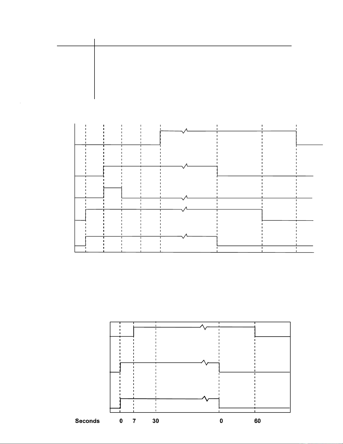
27
Light Signal Refer to Abnormal Heating or Cooling Operation Sections of this Manual
Off Internal Control Failure
1 Flash External Lockout
2 Flashes Pressure Switch Stuck Open
3 Flashes Pressure Switch Stuck Closed
4 Flashes Thermal Protection Device Open
5 Flashes Flame Detected with Gas Valve Closed
6 Flashes Short Cycle Compressor Delay (Cooling Only)
IGNITION CONTROL DIAGNOSTIC INDICATOR CHART
(SINGLE STAGE MODELS ONLY)
0 15 22 45 52 0 29 120, 135,150
Seconds
Gas Valve
Igniter
T
hermostat
100 %
Circulator
Blower
Induced
Draft
Blower
HEATING TIMING CHART
Circulator
Blower
Outdoor Fan
and
Compressor
Thermostat
ON
OFF
ON
OFF
ON
OFF
COOLING TIMING CHART
ON
OFF
ON
OFF
ON
OFF
ON
OFF
OFF
100%
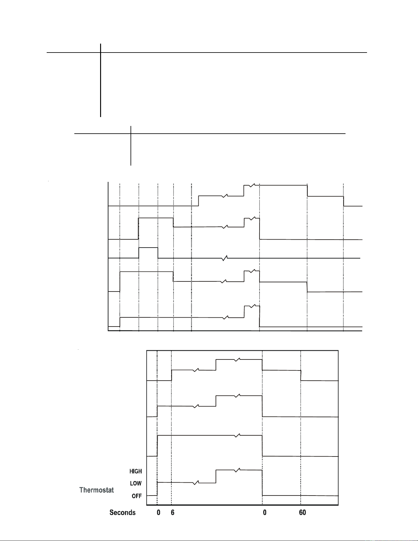
28
HEATING TIMING CHART
COOLING TIMING CHART
Red Light Signal Refer to Abnormal Heating or Cooling Operation Sections of this Manual
Off Internal Control Failure
1 Flash External Lockout
2 Flashes Pressure Switch Stuck Open
3 Flashes Pressure Switch Stuck Closed
4 Flashes Thermal Protection Device Open
5 Flashes Flame Detected with Gas Valve Closed
6 Flashes Short Cycle Compressor Delay (Cooling Only)
7 Flashes Limit Opened Five (5) Times Within The Same Call For Heat
8 Flashes Indoor/Outdoor Thermostat Open (Cooling Only; Devices Not present On All Models)
9 Flashes High Pressure/Loss of Charge Switch Open (Cooling Only; Devices Not Present On All Models)
Amber Light Signal Refer to Abnormal Heating or Cooling Operation Sections of this Manual
Off No Flame Present
On Normal Flame
1 Flash Low Flame Current
2 Flashes Flame Detected with Gas Valve De-energized.
90, 120, 150, 180
C
irculator
B
lower
HIGH
OFF
Seconds
Gas Valve
I
gniter
I
nduced
D
raft
B
lower
T
hermostat
0 15 22 27 52 0 30
LOW
HIGH
OFF
LOW
OFF
ON
HIGH
OFF
LOW
HIGH
OFF
LOW
C
irculator
B
lower
C
ompressor
O
utdoor Fan
HIGH
OFF
LOW
HIGH
OFF
LOW
HIGH
OFF
LOW
IGNITION CONTROL DIAGNOSTIC INDICATOR CHART
(TWO-STAGE MODELS ONLY)
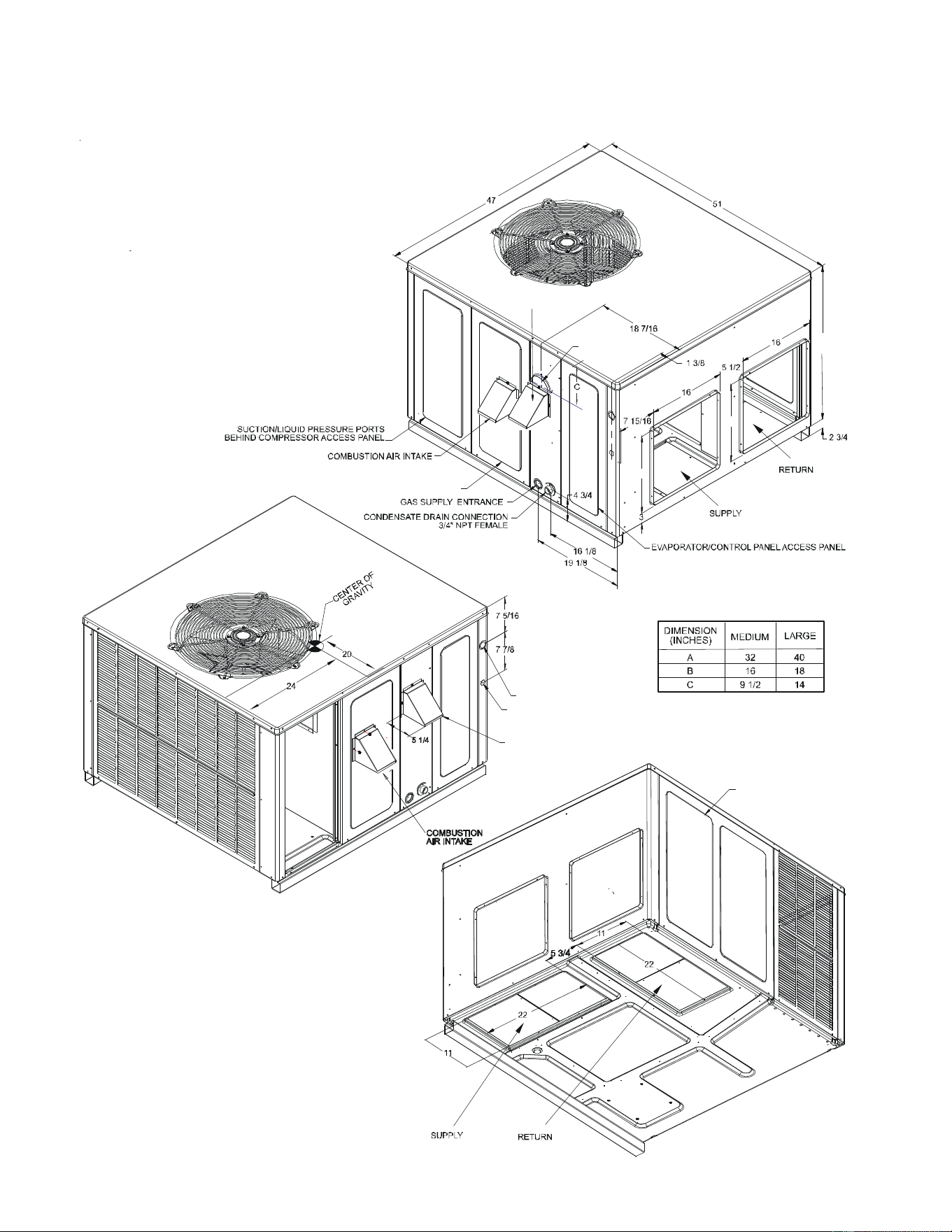
29
APPENDIX
UNIT DIMENSIONS
EXHAUST FLUE HOOD
CONTROL WIRE ENTRANCE
POWER WIRE ENTRANCE
HEAT EXCHANGE ACCESS PANEL
B
B
A
FLUE EXHAUST
BLOWER ACCESS PANEL
FLUE EXHAUST
HOOD
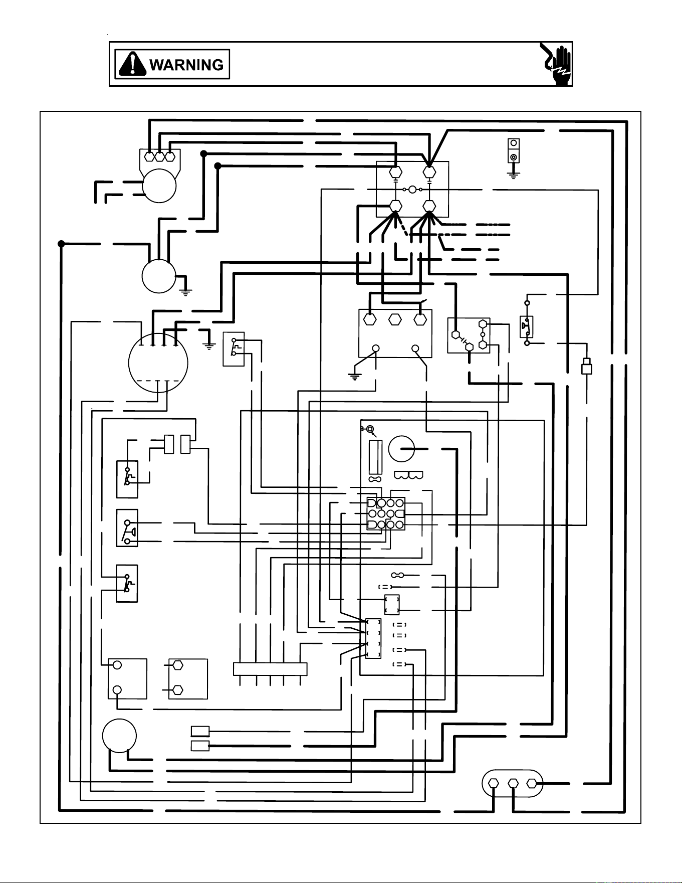
30
*PG14(24, 30, 36, 42)***M41* * WIRING DIAGRAM
Wiring is subject to change. Always refer to the wiring diagram on the unit for the most up-to-date wiring.
HIGH VOLTAGE!
DISCONNECT ALL POWER BEFORE SERVICING OR INSTALLING THIS
UNIT. MULTIPLE POWER SOURCES MAY BE PRESENT. FAILURE TO
DO SO MAY CAUSE PROPERTY DAMAGE, PERSONAL INJURY OR DEATH.
RD
PU
BK
BR
PU
BK
CM
CONNECTED AT L1, L2
BK
BK
NOTE 3
CH OPTIONAL
RS
COMP
C
RD
RD
WH
RD
PU
OR
RD
YL
H
C
F
RD
WH
WH
YL
YL
SEE
NOTE 7
YL
WH
BL
BL
BL
BR
BR
RD
OR
BL
BL
BL
RD
RD
RD
RD
PU
WH
OR
RD
YL
YL
Y
IGN
FS
RCCF
PU
BL
BR
PU
RD
RD
YL
YL
RS
PU
PU
BL
VM
PU
L2
UNUSED
HEAT
FS
L1
DI
1
3
6
5
2
4
10
7
9
12
8
11
150
120
ECON
135
P1
F1
FUSE 3 AMP MAX
P3
GR
RD
YL
WH
YL
YL
COMPRESSOR
COOL
SCREW
REQUIRED
P2
T1
MOUNT
BREAK FOR TWO STAGE
SPEED-UP
GR
WH
WH
GR
RD
C
RD
TO THERMOSTAT
ALS
PS
GV
MV
(ALT.)
HONEYWELL
GAS VALVE
GV
MV
GAS VALVE
W. R.
RS
IIC
HPS
YL
LS
L1
L2
CC
T1
T2
RD
BK
PU
BK
YL
RD
GND
POWER SUPPLY
208-230/1/60
CH OPTIONAL
SEE NOTE 3
BK
BK
1
C
24V
BL
2
TR
3
240
3
4
2
1
RD
VMR
BK PU
PU
BL
PU
YL
208
NOTE 2
SEE NOTE 6
RD
Y
L
BK
BK
YL
NOTE 4
C
T1
T2
T3
T4
T5
LGN
EM
WH
YL
GR
PU
BL
BK
1
2
1
2
RD
BL
BL
PU
PLM-A
PLF-A
YL
BL
BL
BL
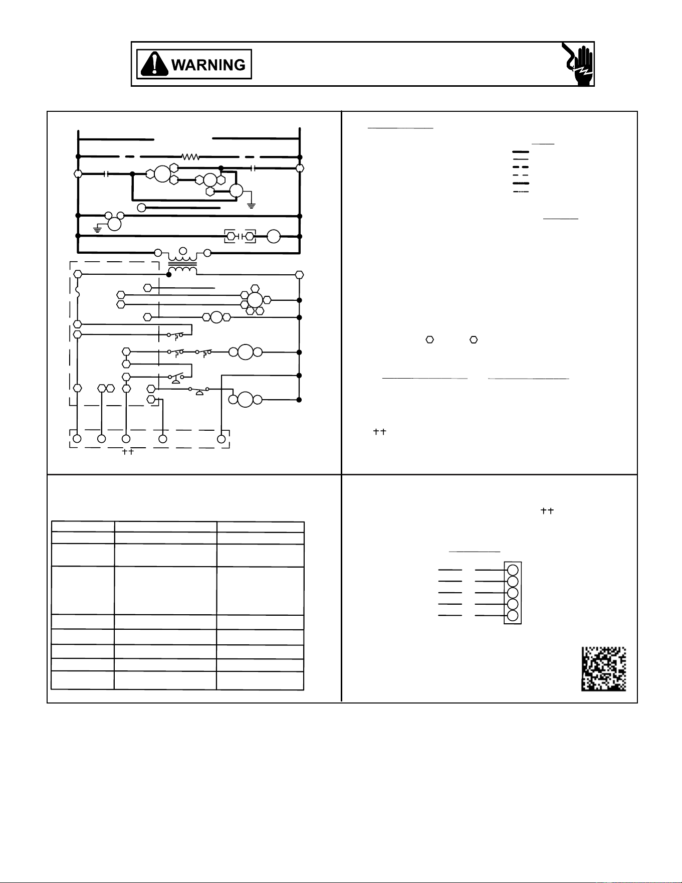
31
0140G03340-A
INSTALLER/SERVICEMAN
-
GAS PRESSURE
FLAME ROLLOUT
AUX. LIMIT OPEN
FLAME SENSOR
BAD SWITCH
GAS VALVE
CHECK FUSE ON CONTROL
CHECK INPUT POWER
REPLACE CONTROL
GAS FLOW
ANTI-CYCLE TIMER
MAIN LIMIT OPEN
STICKING GAS VALVE
BAD SWITCH
3 MIN. COMP.
PRESSURE SWITCH
PRESSURE SWITCH
CHECK
CHECK
OFF
ON
OR
OR
1 BLINK
3 BLINKS
6 BLINKS
2 BLINKS
4 BLINKS
5 BLINKS
FALSE FLAME SENSED
OUTPUT DELAY
OPEN LIMIT SWITCH
COMPRESSOR
WITHOUT INDUCER ON
PRESSURE SWITCH CLOSED
PRESSURE SWITCH
OPEN AUX. LIMIT
OPEN ROLLOUT
SWITCH
OPEN
SWITCH
IGNITION FAILURE
NORMAL OPERATION
NO POWER OR
INTERNAL CONTROL
FAULT
STATUS LIGHT
EQUIP. STATUS
CHECK
TROUBLESHOOTING THIS APPLIANCE. STATUS LIGHT CODES ARE AS FOLLOWS:
THE STATUS LIGHT ON THE FURNACE CONTROL MAY BE USED AS A GUIDE TO
OPTIONAL LOW VOLTAGE
OPTIONAL HIGH VOLTAGE
FIELD INSTALLED CONTROL
FIELD INSTALLED POWER
NOTES :
1. REPLACEMENT WIRE MUST BE THE SAME SIZE AND TYPE OF
INSULATION AS ORIGINAL.(USE COPPER CONDUCTOR ONLY).
2. FOR 208 VOLT TRANSFORMER OPERATION MOVE BLACK WIRE
FROM TERMINAL 3 TO TERMINAL 2 ON TRANSFORMER.
3. CRANKCASE HEATER NOT SUPPLIED ON ALL UNITS.
4. FOR DIFFERENT THAN FACTORY SPEED TAP. CHANGE COOLING
SPEED AT MOTOR T4 AND T5 TERMINALS. CHANGE HEATING
SPEED AT MOTOR T1, T2 AND T3 TERMINALS.
COO
L
ING S
PEED (
YE
L
L
OW
W
I
RE)
HEA
T
I
NG S
PEED (
WH
I
TE
W
I
RE)
T4 - LOW SPEED T1 - LOW SPEED
T5 - HIGH SPEED
T2 - MED. SPEED
T3 - HIGH SPEED
5. USE COOPER CONDUCTORS ONLY
6. L1 AND L2 ON IIC CONTROL IS 24V INPUT.
ALS AUXILLARY LIMIT SWITCH
C CONTACTOR
CH CRANKCASE HEATER
CM CONDENSER MOTOR
COMP COMPRESSOR
EM EVAPORATOR MOTOR
F FUSE
FS FLAME SENSOR
GND EQUIPMENT GROUND
GV GAS VALVE
HPS HIGH PRESSURE SWITCH
IIC INTEGRATED IGNITION CONTROL
IGN IGNITOR
LS LIMIT SWITCH
PLF-A FEMALE PLUG/CONNECTOR ALS
PLM-A FEMALE PLUG/CONNECTOR ALS
PS PRESSURE SWITCH
RCCF RUN CAPACITOR FOR COMPRESSOR/FAN
RS ROLLOUT SWITCH
TR TRANSFORMER
VM VENT MOTOR
VMR VENT MOTOR RELAY
PU - PURPLE
YL - YELLOW
WH - WHITE
RD - RED
BL - BLUE
BR - BROWN
GR - GREEN
OR - ORANGE
PK - PINK
WI
RE
C
O
DE
BK - BLACK
LOW VOLTAGE
WI
RI
N
G
HIGH VOLTAGE
USE NEC CLASS 2 WIRE.
208-230/1/60
BL
YL
RD
GR
WH
N
O E
C
O
N
O
M
IZE
R
W
Y
C
R
G
THERMOSTAT FIELD WIRING
BL/PK - BLUE/PINK
24 V
H
C
EM
RGW Y
TO THERMOSTAT
11
C
4
IIC
ECON
9
7
8
10
12
6
5
3
FS
F
L1
PS
ALS
RS
LS
GV
FS
IGN
VM
L2
SUPPLY VOLTAGE
1
C
COMP
S
C
T1
R
C
CM
208-230/1/60
T2
CH
2
NOTE 3
TR
C
D1
C
13
EM
VMR
VMR
2
NOTE 6
NOTE 6
T4
T3
L
N
3
2
1
IIC
T5
2T
1T
C
RCCF
F
H
NOTE 2
4
HPS
*PG14(24, 30, 36, 42)***M41* * WIRING DIAGRAM
HIGH VOLTAGE!
DISCONNECT ALL POWER BEFORE SERVICING OR INSTALLING THIS
UNIT. MULTIPLE POWER SOURCES MAY BE PRESENT. FAILURE TO
DO SO MAY CAUSE PROPERTY DAMAGE, PERSONAL INJURY OR DEATH.
Wiring is subject to change. Always refer to the wiring diagram on the unit for the most up-to-date wiring.
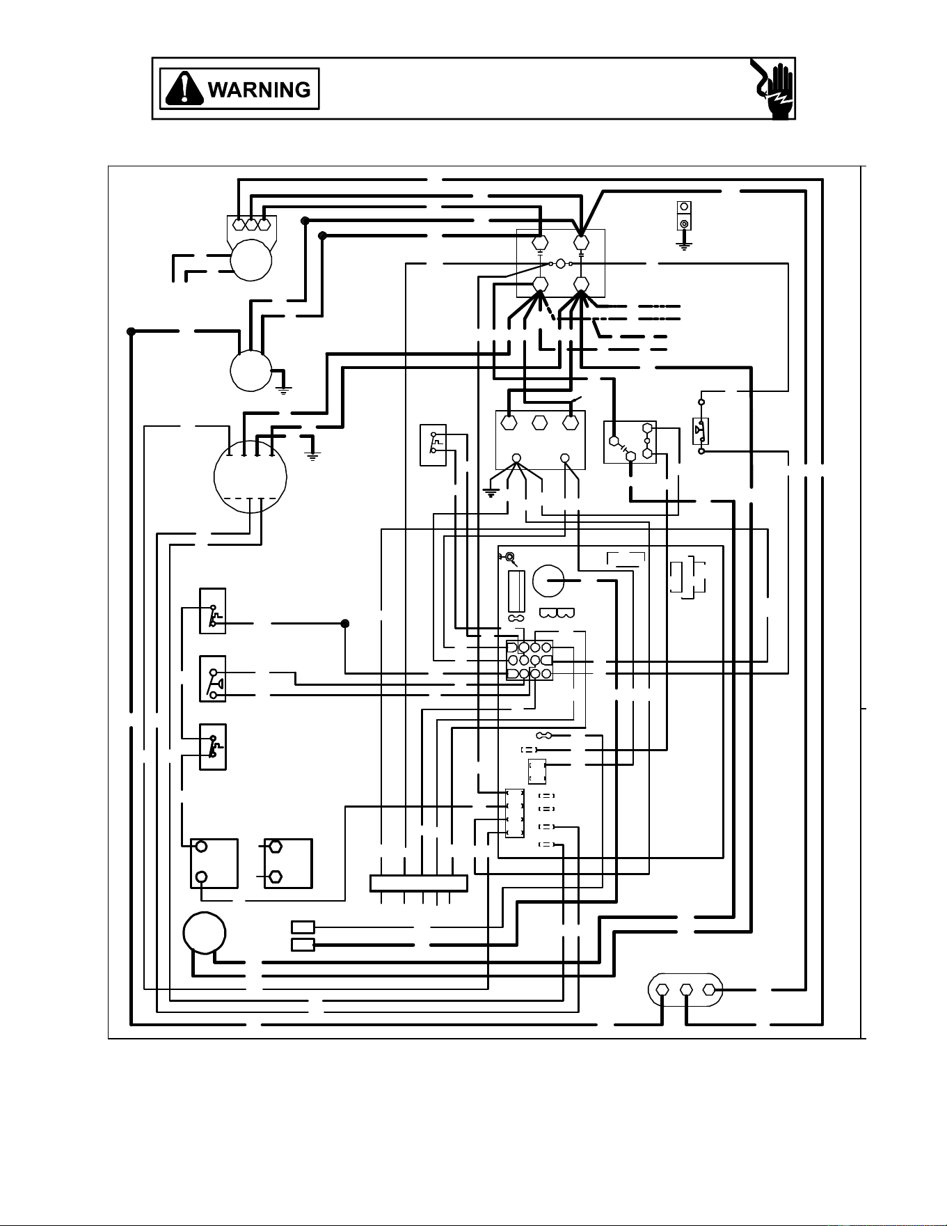
32
PG1448***M41* * WIRING DIAGRAM
Wiring is subject to change. Always refer to the wiring diagram on the unit for the most up-to-date wiring.
HIGH VOLTAGE!
DISCONNECT ALL POWER BEFORE SERVICING OR INSTALLING THIS
UNIT. MULTIPLE POWER SOURCES MAY BE PRESENT. FAILURE TO
DO SO MAY CAUSE PROPERTY DAMAGE, PERSONAL INJURY OR DEATH.
RD
PU
BK
BR
PU
BK
CM
CONNECTED AT L1, L2
BK
BK
NOTE 3
CH OPTIONAL
RS
COMP
C
RD
RD
BL
WH
RD
PU
OR RD
BL
YL
HCF
RD
WH
WH
YL
YL
SEE
NOTE 7
YL
WH
BL
BL
BL
BR
BR
RD
OR
BL
BL
BL
BL
RD
RD
RD
RD
PU
WH
OR
RD
YL
YL
Y/Y2
IGN
FS
RCCF
PU
BL
BR
PU
RD
RD
YL
YL
RS
PU
PU
BL
VM
PU
L2
UNUSED
HEAT
FS
L1
DI
1
3
6
5
2
4
10
7
9
12
8
11
150
120
ECON
135
P1
F1
FUSE 3 AMP MAX
P3
GR
RD
YL
WH
YL
YL
COMPRESSOR
COOL
SCREW
REQUIRED
P2
T1
MOUNT
C22
T2
BREAKFORTWO STAGE
SPE ED-UP
GR
WH
WH
GR
BL
RD
C
RD
TO THERMOSTAT
ALS
PS
GV
MV
(ALT.)
HONEYWELL
GAS VALVE
GV
MV
GAS VALVE
W. R.
RS
IIC
HPS
YL
LS
L1 L2CC
T1
T2
BL
RD
BL
BK
PUBK
YL
RD
GND
POWER SUPPLY
208-230/1/60
CH OPTIONAL
SEE NOTE 3
BK
BK
1
C
24V
BL
RD
2
TR
3
240
3
4
2
1
RD
VMR
BK PU
PU
BL
PU
YL
208
NOTE 2
SEE NOTE 5
RD
YL
BK
BK
YL
BL
NOTE 4
C
T1T2T3 T4T5
LGN
EM
WH
YL
GR
PUBL
BK
YL
YL
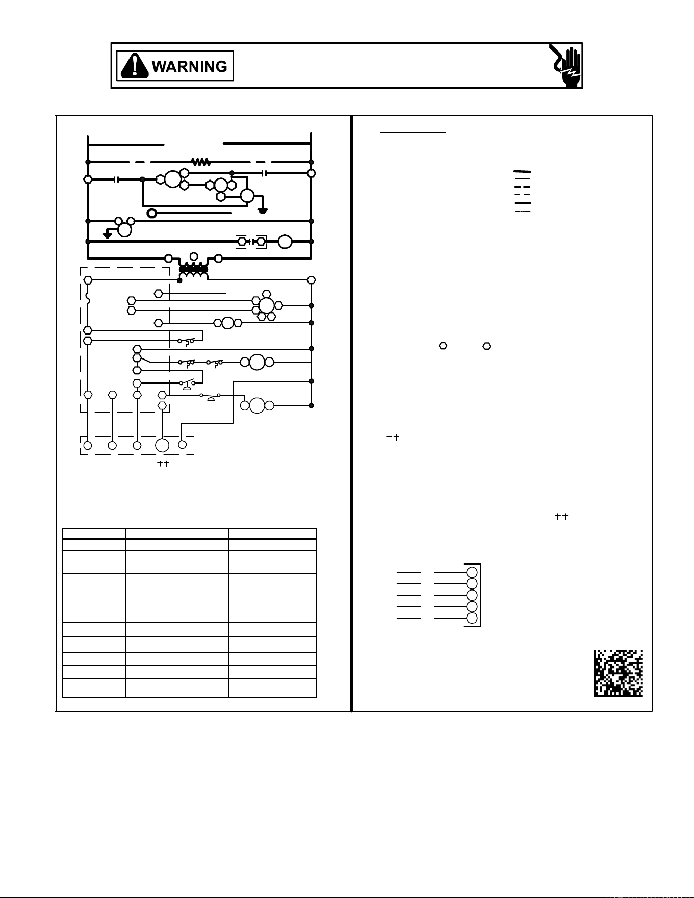
33
*PG1448***M41* * WIRING DIAGRAM
Wiring is subject to change. Always refer to the wiring diagram on the unit for the most up-to-date wiring.
HIGH VOLTAGE!
DISCONNECT ALL POWER BEFORE SERVICING OR INSTALLING THIS
UNIT. MULTIPLE POWER SOURCES MAY BE PRESENT. FAILURE TO
DO SO MAY CAUSE PROPERTY DAMAGE, PERSONAL INJURY OR DEATH.
0140G04507-A
INSTALLER/SERVICEMAN
-
GAS PRESSURE
FLAME ROLLOUT
AUX. LIMIT OPEN
FLAME SENSOR
BAD SWITCH
GAS VALVE
CHECKFUSEONCONTROL
CHECK INPUT POWER
REPLACE CONTROL
GAS FLOW
ANTI-CYCLE TIMER
MAIN LIMIT OPEN
STICK ING G AS V ALVE
BAD SWITCH
3 MIN. COMP.
PRESSURE SWITCH
PRESSURE SWITCH
CHECK
CHECK
OFF
ON
OR
OR
1BLINK
3BLINKS
6BLINKS
2BLINKS
4BLINKS
5BLINKS
FALSE FLAME SENSED
OUTPUT DELAY
OPEN LIMIT SWITCH
COMPRESSOR
WITHOUT INDUCER ON
PRESSURE SWITCH CLOSED
PRESSURE SWITCH
OPEN AUX. LIMIT
OPEN ROLLOUT
SWITCH
OPEN
SWITCH
IGNITION FAILURE
NORMAL O PERATION
NO POWER OR
INTERNAL CONTROL
FAULT
STATUS LIGHT
EQUIP. STATUS
CHECK
TROUBLESHOOTING THIS APPLIANCE. STATUS LIGHT CODES ARE AS FOLLOWS:
THE STATUS LIGHT ON THE FURNACE CONTROL MAY BE USED AS A GUIDE TO
O PTIONAL LOW VOLTAGE
OPTIONAL HIGH VOLTAGE
FIELD INSTALLED CONTROL
FIELD INSTALLED POWER
NOTES :
1.REPLACEMENTWIREMUSTBE THE SAME SIZE AND TYPE OF
INSULATION AS ORIGINAL.(USE COPPER CONDUCTOR ONLY).
2.FOR208 VOLTTRANSFORMEROPERATION MOVEBLACKWIRE
FROMTERMINAL 3 TOTERMINAL 2 ON TRANSFORMER.
3. CRANKCASE HEATER NOT SUPPLIEDON ALL UNI TS.
4.FOR DIFFERE NT T H AN FACTORYSPEEDTAP. CHANGE C OOLING
SPEEDAT MOTOR T4 ANDT5TERMINALS. C HANGE HEATIN G
SPEEDAT MOTOR T1, T2 ANDT3TERMINALS.
CO
OLING SPEED (YELLOW WIRE) HEATING SPEED (WHITE WIRE)
T4 -LOWSPEED T1 -LOWSPEED
T5 -HIGH SPEED T2 - MED. SPEED
T3 - HIGH SPEED
5.USE COOPERCONDUCTORS ONL Y
COMPONENT LEGEND
ALS A UXILLARY LIMIT SWITCH
COMP COMPRESSOR
CM C ONDENSER MOTOR
C CO NTACTOR
CH CRANKCASE HEATER
EM EVAPOR ATOR MOTOR
FFUSE
FS FLAME SENSOR
GND EQUI PMENT GROUND
GV GAS VAL VE
HPS HIGH PRESSURE SWITCH
IIC INTEGR ATED IGNITION CONTROL
IGN IGN ITOR
LS L IMIT SWITCH
PS PRESSURE S WITCH
RCCF R UN CAPACITOR FOR COMPRESSOR/FAN
RS R OLLOUT SWITCH
TR TRANSFORMER
VM VE NT MOTOR
VMR VE NT MOTOR RELAY
PU - PURPLE
YL - YELLOW
WH - WHITE
RD - RED
BL - BLUE
BR - BROWN
GR - GREEN
OR - ORANGE
PK - PINK
WI
RE CODE
BK - BLACK
L OW VOLTAGE
WI
RING
H IGH VOLTAGE
USE NECCLASS2 WIRE.
208-230/1/60
BL
YL
RD
GR
WH
NO E
CONOMIZER
W
Y
C
R
G
THERMOSTAT FIELD WIRING
BL/PK - BLUE/PINK
24 V
H
C
EM
RGW
TO THERMOSTAT
11
Y/Y2
C
4
9
7
8
10 12
6
5
3
FS
F
L1
PS
ALS
RS
LS
GV
FS
IGN
VM
L2
SUPPLY VOLTAGE
1
C
CO M P
S
C
T1
R
L1
C
CM
208-230/1/60
T2
CH
2
L2
NOTE 3
TR
C
D1
C
13
EM
VMR
VMR
2
T4
T3
L
N
3
2
1
IIC
T5
2T1T
C
RCCF
F
H
NOTE 2
4
HPS
2
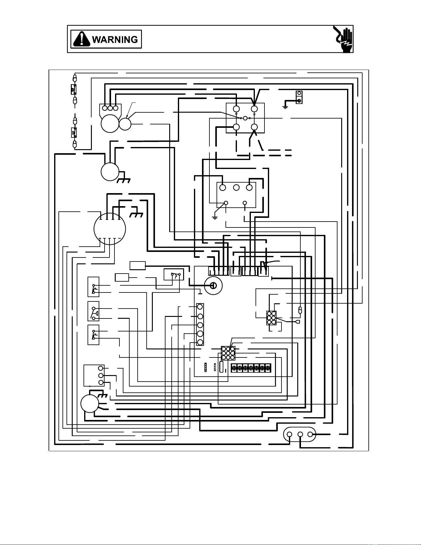
34
SEE NOTE 6
YL
RD
OR
BK
BK
RD
BL
PU
PU
PU
PU
OR
BR
WH
BL
BK
PU
BL
IGN
OR
LS
SOL
HI
LOW
ODF
L1
HIGH
FS
T1
LOW
INDUCER
L2
BK
YL
RD
GR
SEE NOTE 3
EM
208
PU
YL
PU
BK
NGL
T5
T4T3T2
T1
240
3
TR
2
RD
24V
C
1
YL
BL
208-230/1/60
POWER SUPPLY
GND
C
PU
PU
RD
BK
BR
PU
BK
RS
COMP
C
T2
T1
CC
L2L1
ALS
CM
LPS
HPS
PARK
BK
PU
SEE NOTE 3
BL
BK
SEE NOTE 2
YL
YL
YL
YL
YL
YL
YL
YL
YL
PU
FWH
BR
YL
BL
OR
OR
YL
PU
BR
BR
BL
PU
PU
YL
NO NE
5 MIN
10 MIN
180
150
120
90
Y2
Y1
1W2WG
CR
BLOWER
OFF DEL AY
STAGE
DELAY
ECON
LO HEAT
HI HEAT
HI COOL
LO COOL
H
C
M
PU
H
C
F
RD
BR
RCCF
RD
GV
GAS VALVE
W. R.
BK
24VAC COM
PU
5
4
3
2
1
1
2
3
4
5
6
7
8
9
P1
RD
BL
BL
P2
5
4
2
1
36
YL
YL
YL
BK
VM
RD
YL
PU
BL
BR
BR
YL
YL
PS
YL
YL
RS
OR
OR
FS
RD
PU
BK
BL
SEE NOTE 5
PU
Wiring is subject to change. Always refer to the wiring diagram on the unit for the most up-to-date wiring.
HIGH VOLTAGE!
DISCONNECT ALL POWER BEFORE SERVICING OR INSTALLING THIS
UNIT. MULTIPLE POWER SOURCES MAY BE PRESENT. FAILURE TO
DO SO MAY CAUSE PROPERTY DAMAGE, PERSONAL INJURY OR DEATH.
*PG1461***M41** WIRING DIAGRAM
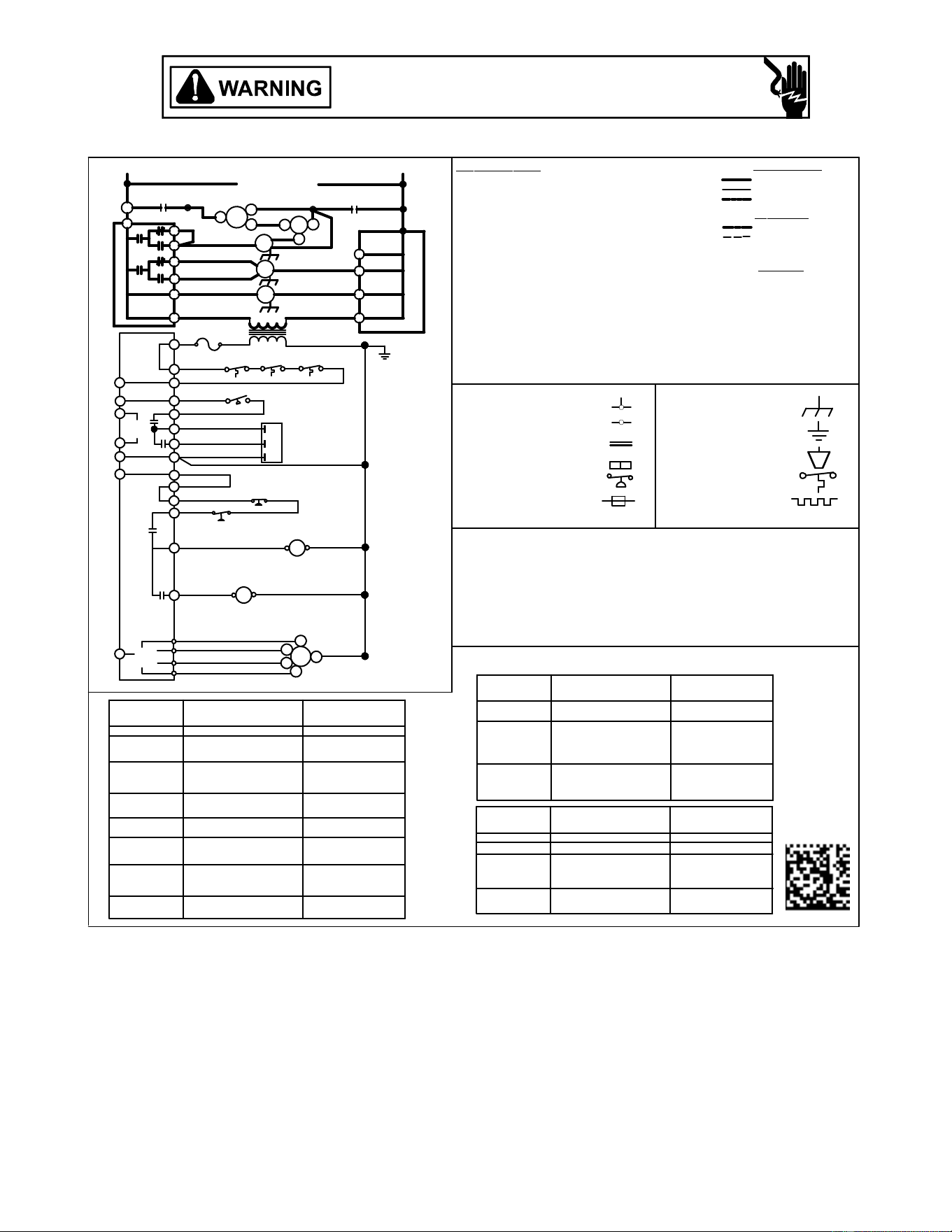
35
G
RUN CAPACITOR FOR COMPRESSOR/FAN
0140G04538-A
FACTOR
Y
WIRING
SOLENOID (2ND STAGE COOL)
SOL
RCCF
FUSE
F
VENT MOTOR
VM
COMPRESSORCOMP
LINE VOLTAGE
OPTIONAL HIGH VOLTAGE
HIGH VOLTAGE
FI
E
LD
WIRING
LOW VOLTAGE
LOW VOLTAGE
BK BLACK
WIRE COD
E
PK PINK
OR ORANGE
GR GREEN
BR BROW N
BL BLUE
RD RED
WH WHITE
YL YELLOW
PU PURPLE
ALS
CC
CM
COM
PONENT
L
EGEND
CONTACTOR
CONDENSER MOTOR
AUXILLARY LIMIT SWITCH
GAS VALVE
GV
FS
GND
IGNITOR
PS
LS
IGN
IIC
EQUIPMENT GROUND
PRESSURE SWITCH
LIMIT SWITCH
INTEGRATED IGNITION CONTROL
FLAME SENSOR
TR
TRANSFORMER
ROLLOUT SWITCH
RS
EM
EVAPORATOR MOTOR
NOTES
1. REPLACEMENT W IRE MUST BE THE SAME SIZE AND TYPE OF
INSULATION AS ORIGINAL.(USE COPPER CONDUCTOR ONLY).
2. FOR 208 VOLT TRANSFORMER OPERATION MOVE BLACK W IRE
FROM TERMINAL 3 TO TERMINAL 2 ON TRANSFORMER.
3. USE COPPER CONDUCTORS ONLY
4. FOR 208V OPERATION, REMOVE BLUE LEAD FROM INDUCER LOW
TERMINAL. MOVE BLACK LEAD FROM PARK TERMINAL ONTO
INDUCER LOW TERMINAL. PLACE BLUE LEAD ON PARK TERMINAL.
5. USE NEC C
LASS 2 WIRE FOR THERMOSTAT FIELD WIRING.
6. COMPRESSOR 2ND STAGE SOLENOID NOT PRESENT ON ALL MODELS.
HI COOL
LO COOL
HI HEAT
LO HEAT
P2
MVC
MVH
MVL
PSW
PSW
HLO
TH
2
3
5
6
4
1
5
7
9
8
6
3
1
2
L1
L1
HI
LO
HI
SOL
GV
T4
T1
T3
T2
EM
C
CC
C
HI
M
RS
PS
LSALS
TR
EM
VM
H
F
RCCF
C
L2
T2
208-230/1/60
CM
L1
R
T1
S
COMP
C
L1
SUPPLY VOLTAGE
P1
INTEGRATED IGNITION CONTROL
CC
CC
COM
HLI
SEE NOTE 2
INTERGRATED IGNITION
CONTROL
F
Y1
R
C
Y2
W2
W1
TO
MICRO
TO
MICRO
INTEGRATED IGNITION CONTROL
L1
LO
L2
L2
L2
L2
SOL
ODF OUTDOOR FAN
HPS
LPS
1
2
3
HIGH PRESSURE SWITCH
HPS
LPS
LOW PRESSURE SWITCH
EQUIPMENT GROUND
FIELD GROUND
FIELD SPLICE
SWITCH (TEMP)
IGNITER
SWITCH (PRESS.)
OVERCURRENT
PROT. DEVICE
JUNCTION
TERMINAL
INTERNAL TO
INTEGRATED CONTROL
PLUG CONNECTION
SEE NOTE 5
REPLACE CONTROL
3 MIN COMP. SHORT
CYCLE DELAY
COMPR. SHORT CYCLE DELAY
6 FLASHES
DIAGNOSTIC
LED - RED
CHECK FOR SHORTS IN
FLAME SENSOR WIRING
CHECK GAS VALVE
CHECK ROLLOUT LIMIT SW.
CHECK AUXILIARY LIMIT SW.
CHECK MAIN LIMIT SWITCH
CHECK WIRING FOR SHORTS
CHECK PRESSURE SWITCH
PRESSURE SW ITCH CLOSED
CHECK VENT MOTOR
CHECK TUBING
CHECK FUSE(S)
CHECK INPUT POWER
-
GAS PRESSURE
FLAME SENSOR
GAS VALVE
GAS FLOW
CHECK PRESSURE SWITCH
OFF
ON
1 FLASH
3 FLASHES
2 FLASHES
4 FLASHES
5 FLASHES
FALSE FLAME DETECTED
OPEN LIMIT SW ITCH
WITHOUT INDUCER ON
PRESSURE SWITCH OPEN
IGNITION FAILURE
NORMAL OPERATION
NO POWER OR
INTERNAL CONTROL
FAULT
STAT US
CHECK
CHECK FOR SHORTS IN
FLAME SENSOR W IRING
-
NORMAL FLAME PRESENT
DIAGNOSTIC
LED - AMBER
-
GAS PRESSURE
FLAME SENSOR
GAS VALVE
GAS FLOW
CHECK GAS VALVE
ON
OFF
1 FLASH
2 FLASHES
FALSE FLAME DETECTED
LOW FLAME SIGNAL
NO FLAME PRESENT
STAT US
CHECK
PSW/LOC OPEN
9 FLASHES
CHECK JUMPER BET W EEN 1
AND 4 ON 6-CIRCUIT
CONNECTOR
IDT/ODT OPEN
8 FLASHES
CHECK AUXILIARY LIMIT SW.
CHECK MAIN LIMIT SWITCH
LIMIT OPEN 5 TIMES IN SAME
CALL FOR HEAT
DIAGNOSTIC
LED - RED
7 FLASHES
STAT US
CHECK
CHECK OPTIONAL
REFRIGERANT SW ITCHES
CHECK REFRIGERANT
SWITCHES FOR LOSS OF
CHARGE OR HIGH HEAD
PRESSURE
HLO HI LIMIT OUTPUT
HLI HI LIMIT INPUT
PSW PRESSURE SWITCH
MVL MAIN GAS VALVE LOW
MVH MAIN GAS VALVE HIGH
TH TRANSFORMER HIGH
MVC MVC MAIN GAS VALVE COMMON
*PG1461***M41** WIRING DIAGRAM
Wiring is subject to change. Always refer to the wiring diagram on the unit for the most up-to-date wiring.
HIGH VOLTAGE!
DISCONNECT ALL POWER BEFORE SERVICING OR INSTALLING THIS
UNIT. MULTIPLE POWER SOURCES MAY BE PRESENT. FAILURE TO
DO SO MAY CAUSE PROPERTY DAMAGE, PERSONAL INJURY OR DEATH.
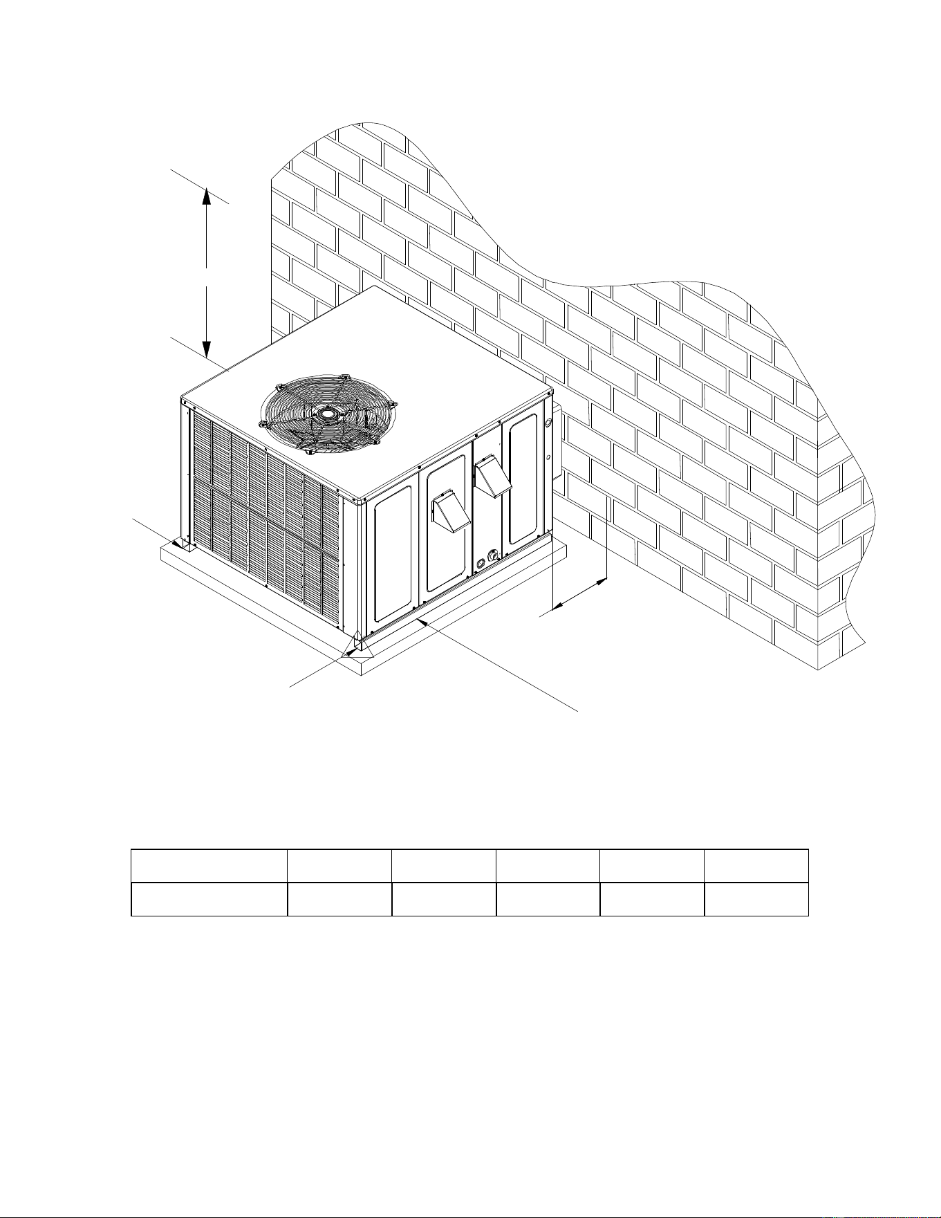
36
RECOMMENDED FILTER SIZES
UNIT 2 Ton 2 1/2 Ton 3 Ton 3 1/2 / 4 Ton 5 Ton
Min. Filter Size (1)20 x 20 x 1 (1)20 x 25 x 1 (1)25 x 25 x1 (2)20 x 20 x 1 (2)20 x 25 x
1
MINIMUM CLEARANCES
-
NOTE: Roof overhang should be no more than 36".
3"
MIN
12" MIN
12" MIN
36" MIN
(FOR SERVICE)
.
48" MIN
Clearance in accordance with local installation codes,
the requirements of the gas supplier and the
manufacturer’s installation instructions.
Dégaugement conforme aux codes d’installation
locaux, aux exigences du fournisseur de gaz et aux
instructions d’installation du fabricant.
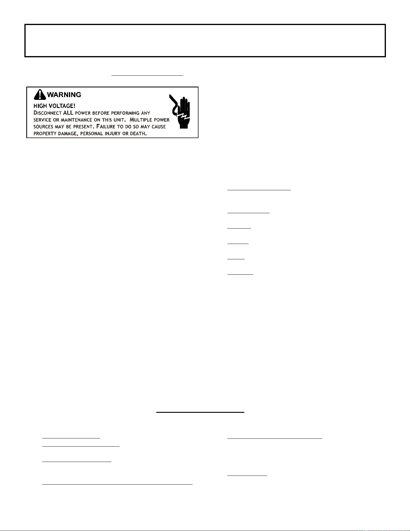
37
PACKAGE UNITS - DUAL FUEL & GAS
HOMEOWNER’S ROUTINE MAINTENANCE RECOMMENDATIONS
We strongly recommend a bi-annual maintenance checkup be performed
by a
qualified service agency before the heating and cooling seasons begin.
REPLACE OR CLEAN FILTER
IMPORTANT NOTE: Never operate unit without a filter installed as
dust and lint will build up on internal parts resulting in loss of
efficiency, equipment damage and possible fire.
A return air filter is not supplied with this unit; however, there must
be a means of filtering the return air. An indoor air filter must be
used with your comfort system. A properly maintained filter will
keep the indoor coil of your comfort system clean. A dirty coil could
cause poor operation and/or severe equipment damage.
The installer of your unit can tell you where your filter(s) are and
how to clean or replace them.
Check your return filter(s) at least once every two months. When
they are dirty, replace or clean as required. Disposable type
filters should be replaced. Reusable type filters may be cleaned.
NOTE: Reusable type filters should be washed with warm water,
dried completely and sprayed with an adhesive according to the
manufacturers recommendations.
You may want to ask your dealer about high efficiency filters. High
efficiency filters are available in both electronic and non-electronic
types. These filters can do a better job of catching small airborne
particles.
Improper filter maintenance is the most common cause of inad-
equate heating or cooling performance. Filters should be cleaned
(permanent) or replaced (disposable) every two months or as re-
quired. When replacing a filter, it must be replaced with a filter of
the same type and size and always make certain the air flow
arrows on the filter point in the proper direction.
CONDENSER, EVAPORATOR AND INDUCED DRAFT MOTORS
The bearings on the air circulating blower motor, condenser motor
and the combustion fan motor are permanently lubricated and
require no further lubrication.
COMPRESSOR
The compressor motor is hermetically sealed and does not re-
quire additional oiling.
ANNUAL INSPECTION (QUALIFIED SERVICER ONLY)
Your package unit should be inspected by a qualified installer,
or service agency at least twice every year. This check should
be performed before the heating and cooling seasons begin.
This will ensure that adequate combustion air is being drawn
and the vent system is working properly. Particular attention
should be paid to the following items. Repair as necessary.
• Check physical support of the unit. Ensure it is sound
without any sagging, cracks, or gaps, around the base.
• Check for obvious signs of deterioration of the unit.
• Flue Hood and Combustion Air Inlet. Check for blockage
(wasp nest, etc.) and corrosion.
F
LUE HOOD (QUALIFIED SERVICER ONLY)
• Return Air Connection. Check for physical soundness
and ensure that the connection is firmly sealed to the
package unit casing.
• Heat exchanger. Check for corrosion and/or obstructions
within the heat exchanger passageways.
• Burners. Check for proper ignition, burner flame, and
flame sense.
• Wiring. Check wires for damage. Check electrical
connections for tightness and/or corrosion.
• Filters. Check that filters are clean and in the proper
placement in the unit or duct system.
• Louvers. Inspect air inlet louvers inside the heat
exchanger compartments. Ensure the area is clean and
free of dirt and debris.
Clean Outside Coil (Qualified Servicer Only)
The outdoor coil should be inspected annually. It is important to
keep the outdoor coil clean. Dirt, leaves, or debris could restrict the
airflow. If cleaning of the outdoor coil becomes necessary, hire a
qualified servicer. Inexperienced people could easily puncture the
tubing in the coil.
BEFORE CALLING YOUR SERVICER
• Check the thermostat to confirm that it is properly set.
• Check the disconnect switch near the unit to confirm that
it is closed.
• Check the electrical panel for tripped circuit breakers or
failed fuses . Reset the circuit breakers or replace fuses
as necessary.
• Check for blockage of the indoor air inlets and outlets.
Confirm that they are open and have not been blocked by
objects (rugs, curtains or furniture).
•
Check for obstructions on the unit . Confirm that it has
not been covered on the sides or the top. Remove any
obstruction that can be safely removed. If the unit is
covered with dirt or debris, call a qualified servicer to
clean it.
• Check the filter. If it is dirty, clean or replace it.
38
Verify all packaging material has been removed.
Remove all shipping brackets per installation instructions.
Verify the job site voltage agrees with the unit serial plate.
Verify condensate connection is installed per installation instructions.
Verify proper clearance around the unit for safety, service, maintenance and proper unit operation.
Verify proper weatherproofing of all ductwork, roof curbs and electrical connections.
Check that the flue screen is in place.
Check gas piping for leaks.
Verify gas pressure to the unit is within the range specified on the serial plate.
Check to ensure that all fans, pulleys and wheels are secure.
Check for proper belt tension and alignment per installation instructions.
Check refrigerant piping for rubbing and leaks. Repair if necessary.
Check unit wiring to ensure it is not in contact with refrigerant piping or sharp metal edges.
Check all electrical connections and terminals. Tighten as needed.
Verify that the crankcase heaters have been energized for 24 hours.
Verify the scroll compressor(s) are rotating in the right direction.
Verify all accessories are installed and operating correctly.
Check filters and replace if necessary.
Verify the installation of the thermostat.
Start-up Checklist
*Store in job file
Pre Start-Up
(Check each item as completed)
9/2014
Date: ___________________________________
Model Number: ___________________________________
Serial Number: ___________________________________
Technician: ___________________________________
Location: __________________________________________
__________________________________________
__________________________________________
Unit #: __________________________________________
A
ir Conditioning & Heatin
g
is a registered trademark of Maytag Corporation or its related companies and is used under license to Goodman Company, L.P., Houston, TX, USA. All rights reserved.

39
Start-up Checklist
L1 - L2 L2 - L3 L3 - L1
L1 L2 L3
L1 L2 L3
L1 L2 L3
Fan 1 Fan 2 Fan 3
IN. W.C.
IN. W.C.
IN. W.C.
RPM
DB WB
DB WB
DB WB
DB
IN. W.C.
IN. W.C. (Low Fire) IN. W.C. (High Fire)
PSIG °F
°F
PSIG °F
°F
PSIG °F
°F
PSIG °F
°F
PSIG °F
PSIG °F
PSIG °F
PSIG °F
BLOWER EXTERNAL STATIC PRESSURE
Return Air Static Pressure
Supply Air Static Pressure
Supply Voltage
Circuit 1 Compressor Amps
Circuit 2 Compressor Amps
Blower Amps
Condenser Fan Amps
ELECTRICAL
Total External Static Pressure
Blower Wheel RPM
TEMPERATURES
Outdoor Air Temperature
Return Air Temperature
Cooling Supply Air Temperature
Discharge Circuit 1
Heating Supply Air Temperature
PRESSURES
Gas Inlet Pressure
Gas Manifold Pressure
Suction Circuit 1
Suction Circuit 2
Discharge Circuit 2
Superheat (Orifice System)
Superheat (Orifice System)
Subcooling (TXV System)
Subcooling (TXV System)
Discharge Circuit 1
Discharge Circuit 2
(HEAT PUMP ONLY)
Suction Circuit 1
Suction Circuit 2
Start-Up
(Insert the values as each item is completed.)
A
ir Conditioning & Heating
40
Goodman Company, L.P.
5151 San Felipe, Suite 500, Houston, TX 77056
www.goodmanmfg.com - or - www.amana-hac.com
© 2014-2019 Goodman Company, L.P.
is a registered trademark of Maytag Corporation or its related companies and is used under license to Goodman Company, L.P., Houston, TX, USA. All rights reserved.
GOODMAN® BRAND
AMANA® BRAND
CUSTOMER FEEDBACK
We are very interested in all product comments.
Please fill out the feedback on one of the following links:
Goodman® Brand Products:
(http://www.goodmanmfg.com/about/contact-us).
Amana® Brand Products: (http://www.amana-hac.com/about-us/contact-us).
You can also scan the QR code on the right for the product brand
you purchased to be direced to the feedback page.
Product Registration
Thank you for your recent purchase. Though not required to get the protection of
the standard waranty, registering your product is a relatively short process, and
entitles you to additional warranty protection, except that failure by California ad Quebec
residents to register their product does not diminsh their warranty rights.
For Product Registration p
lease register by following this link:
Goodman® Brand Products: (https://www.goodmanmfg.com/product-registration).
Amana® Brand Products: (http://www.amana-hac.com/product-registration).
You can also scan the QR code on the right to be directed to the Product Registration Page.
GOODMAN® BRAND
AMANA® BRAND
Goodman Company, L.P., reserves the right to discontinue, or change at any time, specifications,
applications or designs without notice or without incurring obligations.