AL24 1 05/15/12
AlwAys reAd
instructions
before using
power tools
AlwAys weAr
sAfety goggles
weAr heAring
protection
Avoid
prolonged
exposure to
vibrAtion
some dust created by power sanding, sawing, grinding, drilling, and other construction
activities contains chemicals known to cause cancer, birth defects or other reproductive
harm. some examples of these chemicals are:
• leadfromlead-basedpaints,
• crystallinesilicafrombricksandcementandothermasonryproducts,and
• arsenicandchromiumfromchemically-treatedlumber.
your risk from these exposures varies, depending on how often you do this type of
work. to reduce your exposure to these chemicals: work in a well ventilated area, and
work with approved safety equipment, such as those dust masks that are specially
designed to filter out microscopic particles.
Copyright © Professional Tool Products, 2012
All rights reserved.
AL24
Operating Instructions • Warning Information • Parts Breakdown
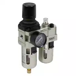
Adjustable Pressure Range ........5-120 PSIG (.3-8 bar)
Maximum Service Pressure ..........140 PSIG (9.7 bar)
Maximum Air Flow...................... 575 SCFM
Oil Capacity .............................2.4 fl. oz.
AL24
Operating Temperature Range .......41 - 140ºF (5-60ºC)
Weight...................................3.7 lbs.
Dimensions .................W 6.3" x H 9.0" x D 4.0"
SPECIFICATIONS
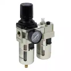
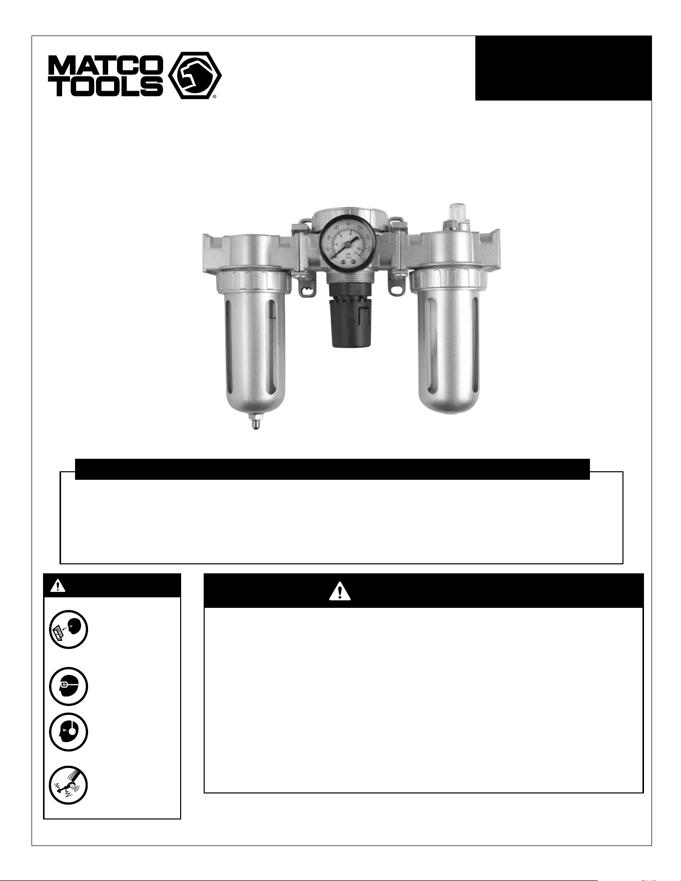
FILTER, LUBRICATOR
AND REGULATOR UNIT
AL24 2 05/15/12
AL24 FILTER, LUBRICATOR AND REGULATOR UNIT
This insTrucTion MAnuAL conTAins
iMporTAnT sAfeTy inforMATion.
reAd This insTrucTion MAnuAL cArefuLLy
And undersTAnd ALL inforMATion Before
operATing This TooL.
• Always operate, inspect and maintain this tool in
accordancewithAmericanNationalStandardsInstitute
SafetyCodeofPortableAirTools(ANSIB186.1)andany
otherapplicablesafetycodesandregulations.
• For safety, top performance and maximum durability of
parts, operate this tool at 90 psig; 6.2 bar max air
pressurewith3/8"diameterairsupplyhose.
• Always wearimpact-resistant eye andface protection
whenoperatingorperformingmaintenanceonthistool.
• Always wear hearing protection when using this tool.
High sound levels can cause permanent hearing loss.
Use hearing protection as recommended by your
employerorOSHAregulation.
• Keepthetoolinefficientoperatingcondition.
• Operators and maintenance personnel must be
physicallyabletohandlethebulk,weightandpowerof
thistool.
• Airpoweredtoolscanvibrateinuse.Vibration,repetitive
motions or uncomfortable positions over extended
periodsoftimemaybeharmfultoyourhandsandarms.
Discontinue use oftool if discomfort,tingling feeling or
painoccurs.Seekmedicaladvicebeforeresuminguse.
• Airunderpressurecancausesevereinjury.Neverdirect
airatyourselforothers.Alwaysturnofftheairsupply,
drainhoseofairpressureanddetachtoolfromairsupply
before installing, removingor adjusting anyaccessory
onthis tool, orbefore performingany maintenanceon
this tool. Failure to do so could result in injury. Whip
hoses can cause serious injury. Always check for
damaged,frayedorloosehosesandfittings,andreplace
immediately.Donotusequickdetachcouplingsattool.
Seeinstructionsforcorrectset-up.
• Slipping, tripping and/or falling while operating air
tools can be a major cause of serious injury or
death. Be aware of excess hose left on the walking
orworksurface.
• Keep body working stance balanced and firm. Do
notoverreachwhenoperatingthetool.
• Anticipate and be alert for sudden changes in motion
duringstartupandoperationofanypowertool.
• Do not carry tool by the hose. Protect the hose from
sharpobjectsandheat.
• Toolshaftmaycontinuetorotatebrieflyafterthrottleis
released. Avoid direct contact with accessories
duringandafteruse.Gloveswillreducetheriskofcuts
orburns.
• Donotlubricatetoolswithflammableorvolatileliquids
suchaskerosene,dieselorjetfuel.
• Donotforcetoolbeyonditsratedcapacity.
• Donotremoveanylabels.Replacedamagedlabels.
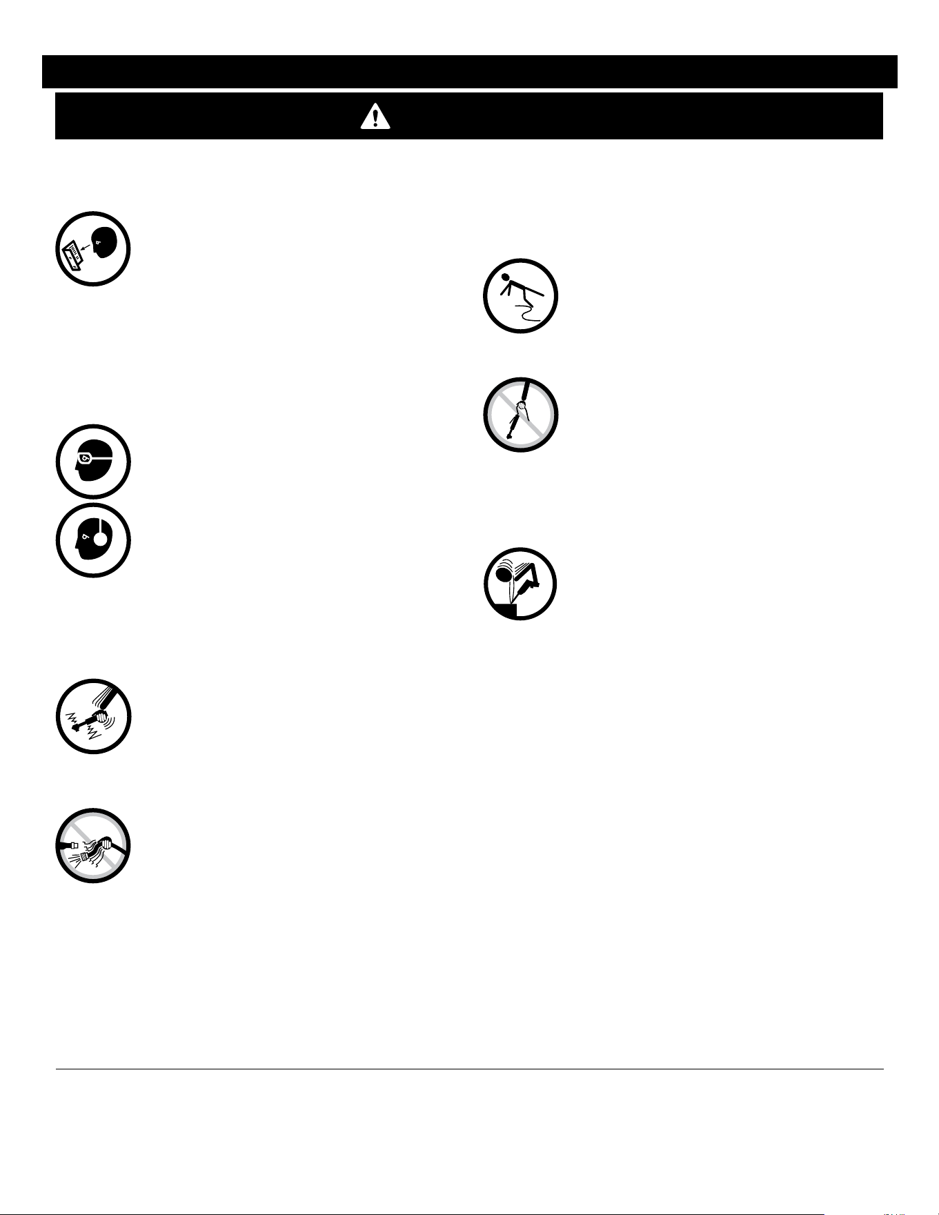
• Pressuresystemscanleakcausingflyingparticles.
• Wearsafetygoggles(Userandbystanders).
• Readandfollowinstructions.
• Flyingparticlescancauseinjury.
• Compressorsystemscontainairunderpressure.
• Relievepressurebeforeservicing.
• Apressurizedairstreamcancauseinjury.
• AirfrominlineLubricatorsmaycontainoilorother
harmfulmaterial.
• Useinwellventilatedarea.
• Oil and other impurities in breathing supply air can
causeinjury.
• WARNING:Handlingthebrasspartsofthis
productwillexposeyoutolead,achemicalknown
totheStateofCaliforniatocausebirthdefectsand
otherreproductiveharm.Washhandsafterhandling.
fAiLure To oBserVe These WArnings couLd resuLT in inJury
descripTion
This Filter/Regulator/Lubricator is a 3 part system. The filter is
designedtoremove mostliquid andsolid particlesfrom theair
supply.Theself-relievingpressureregulatorisusedtoadjustthe
outletpressurebetween0-140PSI.Thelubricatorprovidesoilto
theairtoolandincreasesthelifeofthetool.
WARNING

AL24 3 05/15/12
AL24 FILTER, LUBRICATOR AND REGULATOR UNIT
insTALLATion of fiLTer/reguLATor
1. Maximumairpressuretounitis140PSIG(9.7BAR).
2. Mounttheunitasclosetotheitemtobeprotectedaspossible.
3. Directionofairflowisdesignatedbyan""and""onthe
primaryunit.
4.Positionthewaterdischargevalve(#12)withthe""pointing
upward.
5. Properwaterdrainageshouldbeallowedbeneaththewater
discharge valve (#12). Provide a container to catch the water
drainageorattacharubberhosetochannelthewaterawayfrom
walkareatoavoidcreatingahazardouswalkingarea.
6. InstallDialGauge(#52) byscrewingbrassfittingon backof
Gaugeclockwiseintothethreadedholeprovidedinfrontofthe
primaryunit,justabovetheregulatoradjustmentknob(#27).
reguLATion of Air pressure
1. Unlockadjustingknob(#27)bypullingdowngently,thenturn
theknobclockwisetoincreaseairpressureandcounterclockwise
todecreaseairpressure.
2. After setting the desired air pressure, push up on the
adjustment knob (#27) until the knob clicks back into the lock
position. At this point, the adjustment knob should not turn in
eitherdirection.
3. Do not exceed any pressure ratingof any component in the
system.
drAinAge
1. Notethatwhenthereisnoairpressuresuppliedtotheunit,
anywaterintheunitwillautomaticallydischarge.
2. When air pressure is supplied to the unit, water may be
discharged byturning the waterdischarge valve (#12)until the
""ispointeddown.NOTE:Whenthewaterlevelexceedsthe
maximumlevelasnotedontheshatterguard.(#3),drainthewater
sothatoptimaldehumidificationcanbemaintained.
MAinTenAnce
1. Beforeperforminganymaintenanceonthisunit,shutoffthe
airsupplytotheunitandcompletelydischargeallairuntilnoair
pressure exists in the unit. Avoid breathing any discharged air
directly.
WARNING:APRESSURIZEDSTREAMOFAIR
CANCAUSESERIOUSINJURY!
2. Unscrew shatterguard (#3) counterclockwise and remove.
Then,unscrewthebowlbaffle(#6)counterclockwiseandremove,
beingcarefulnottolosetheintercepter(#8).Thefilter(#7)may
then be removed and rinsed of any debris. The filter may be
reinstalledforrepeateduse.
3.Cleanthetransparentbowl(#2)withaclean,drycloth.Donot
use any chemical that might damage the bowl material. Upon
reassembly, be sure bowl baffle (#6) and shatterguard (#3) are
securelytightened.
WARNING!
Pressuresystemscanleakcausingflyingparticles.
Wearsafetygoggles.(Userandbystanders).
Readandfollowinstructions.
Flyingparticlescancauseinjury.
Compressorsystemscontainairunderpressurethatcancreate
ahighpressurestream.
Relievepressurebeforeservicing.
Apressurizedairstreamcancauseinjury.
insTALLATion of LuBricATor
1. Ensure that the Filter/Regulator installation is complete
BEFORE installingtheLubricator.
2.UseISO-VG32orsimilarlubricant.
3.Addlubricantintotheoilbowl(#34)throughthefillplug(#40)
opening. Unscrew the fill plug by turning counterclockwise.
Do not fill past "Max Oil Level" line indicated on the outside of
shatterguard. After filling the oil bowl, replace the oil fill plug
securely.
4. Duringoperation,airflowdoesnothavetobeshutofftoadd
lubricant.Lubricantcanbeaddedanytimebyusingtheoilfillplug
asnotedabove.
WARNING:NEVERREMOVETHEBOWLTOADD
LUBRICANT.ALWAYSUSEFILLPLUGOPENING.
reguLATing oiL drop
1. To regulate the amount of oil dropped during air flow,
use adjusting screw (#27) on top of Lubricator. Turn screw
counterclockwiseformoreoilandclockwiseforlessoil.NOTE:
After settingthe desiredoil drop usingthe adjustingscrew,be
awarethatasairflowisregulatedupordown,theoildropwill
bechangedalso.Moreairflowwillincreaseoildropandlessair
flowwilldecreaseoildrop.
WARNING:APRESSURIZEDSTREAMOFAIR
CANCAUSESERIOUSINJURY!
2. Unscrew shatterguard counterclockwise and remove, being
carefulnottolosetheO-Ring(#5).
3.Cleanthetransparentbowl(#34)withaclean,drycloth.Donot
use any chemical that might damage the bowl material. When
reassembling,besuretheO-ringisintheproperpositionandthe
shatterguardissecurelytightened.

AL24 4 05/15/12
AL24 FILTER, LUBRICATOR AND REGULATOR UNIT
4.Beadvisedthattheplasticpartscouldshowsignsofpremature
aging and discoloration if exposed to paints, inferior grade
lubricants,detergentsorotherchemicals.
WARNING:THISUNITISNOTTOBEUSEDWITHANY
OTHER FLUIDS, ESPECIALLY FLAMMABLE LIQUIDS SUCH AS
GASOLINEORALCOHOL.SERIOUSDAMAGEORINJURYTOTHE
USERCOULDRESULT.
WArrAnTy
Matco® air tool accessories are warranted against defects in
materials or workmanship for a period of 1 year from original
purchase.Wewillrepairorreplaceatouroptionanydefectivepart
orunitwhichprovestobedefectiveinmaterialorworkmanship
withinthiswarrantyplan.Thiswarrantydoesnotcoverdamage
toaccessoriesarisingfromalteration,abuseormisuse,anddoes
notcoveranyrepairsorreplacementmadebyanyoneotherthan
Matcooritsauthorizedservicecenters.
The foregoingobligation isMatco Tools soleliability under this
oranyimpliedwarrantyandundernocircumstancesshallwebe
liableforanyincidentalorconsequentialdamages.
NOTE: Some states do not allow the exclusion or limitation of
incidentalorconsequentialdamages,sotheabovelimitationor
exclusionmaynotapplytoyou.
ReturnairtoolaccessoriestoMatcoToolstransportationprepaid.
Be certain to include your name and address, evidence of the
purchasedate,anddescriptionofthesuspecteddefect.
Ifyou haveanyquestionsabout warrantyservice,please write
toMatcoTools,Stow,OH44224.Thiswarrantygivesyouspecific
legalrightsandyoumayalsohaveotherrightswhichvaryfrom
statetostate.
AL24 5 05/15/12
AL24 FILTER, LUBRICATOR AND REGULATOR UNIT
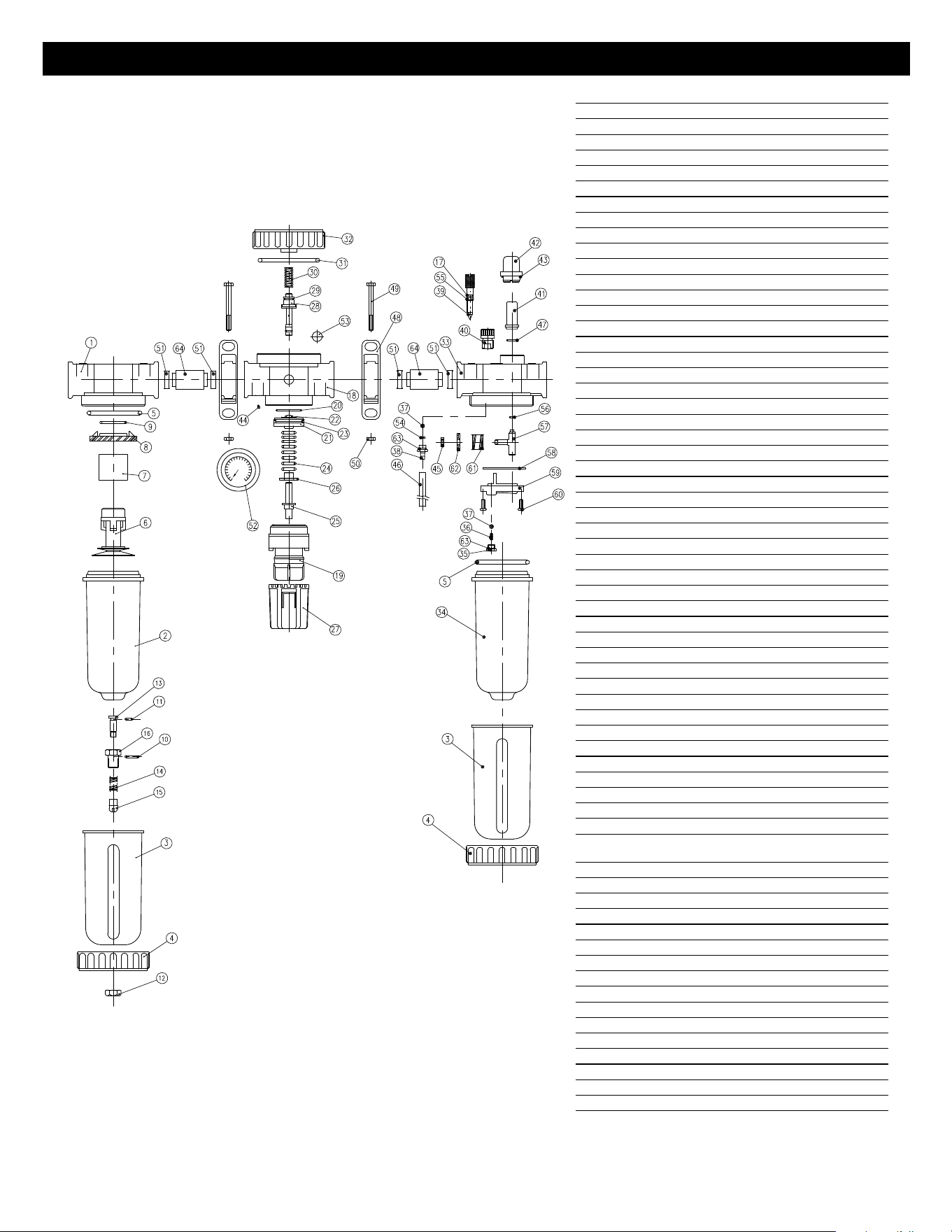
ITEM PARTNO. DESCRIPTION QTY.
1 Body 1
2 RSAL2002 Bowl 1
3 RSAL2003 Shatterguard 1
4 RSAL2004 FixedRing 1
5 RSAL2005 O-Ring 1
6 BowlBaffle 1
7 RSAL2007 FilterElement 1
8 Interceptor 1
9 O-Ring 1
10 RSAL2010 O-Ring 1
11 RSAL2011 O-Ring 1
12 RSAL2012 Nut 1
13 RSAL2013 Piston 1
14 RSAL2014 Spring 1
15 RSAL2015 Piston 1
16 RSAL2016 Body 1
17 O-Ring 1
18 Body 1
19 Dome 1
20 O-Ring 1
21 Piston 1
22 O-Ring 1
23 V-Ring 1
24 Spring 1
25 AdjustingScrew 1
26 Nut 1
27 Knob 1
28 Valve 1
29 O-Ring 1
30 Spring 1
31 O-Ring 1
32 Cap 1
33 Body 1
34 RSAL2202 Bowl 1
35 Nut 1
36 Spring 1
37 Ball 1
38 Plug 1
39 AdjustingScrew 1
40 FillPlug 1
41 InsideCup 1
42 OutsideCup 1
43 O-ring 1
44 ThrottlePlug 1
45 Screw 1
46 Tube 1
47 O-Ring 1
48 RSAL2448 ConnectAssembly
[Includes#48-#50,#51(2),#64] 2
49 Screw(Includedwith#48) 2
50 Nut(Includedwith#48) 2
51 O-Ring(Includedwith#48) 4
52 RSAL2119 Gauge 1
53 Nut 1
54 O-Ring 1
55 RSAL2011 O-Ring 1
56 O-Ring 1
57 Bracket 1
58 Spacer 1
59 Mount 1
60 Screw 1
61 Spring 1
62 AdjustingRing 1
63 O-Ring 1
64 ConnectLink(Includedwith#48)2
Onlyitemsidentifiedbypartnumbersare
availableforpurchase.
AL24 6 05/15/12
Copyright © Professional Tool Products, 2012
Todos los derechos reservados
AL24
instrucciones de operación • Inforación de Advertencia • Revisión de Refacciones
Rango de presión ajustable . . . . . . . .5-120 PSIG (.3-8 bar)
Máxima presión de servicio ..........140 PSIG (9.7 bar)
Máximo flujo de aire .................... 575 SCFM
Capacidad de aceite ......................2.4 fl. oz.
AL24
Rango de temperatura de operación ..41 - 140ºF (5-60ºC)
Peso ....................................3.7 lbs.
Dimensiones ................W 6.3" x H 9.0" x D 4.0"
ESPECIFICACIONES
Elpolvocreadoporlalijacióneléctrica,laaserradura,latrituración,laperforacióny
otrasactividadesdeconstruccióncontienequímicosconocidoscomocausantesde
cáncer,defectosdenacimientouotrosdañosareproducción.Algunosejemplosde
dichosquímicosson:
•Elplomoprovenientedepinturaconbasedeplomo,
•Lasilicacristalinadeladrilloycementoyotrosproductosdemampostería,y
•Elarsénicoyelcromiodemaderosquímicamentetratados.
Elriesgodedichasexposicionesvaría,dependiendodelafrecuenciaconlacualusted
realiceestetipodetrabajo.Parareducirsuexposiciónadichosquímicos:trabajeen
unaáreabienventiladayconequipodeseguridadaprobado,talescomolosmáscaras
anti-polvo,losquesonespecíficamentediseñadosparafiltrarlaspartículas
microscópicas.
LEERSIEMPRELAS
INSTRUCCIONES
ANTESDE
USARLAS
HERRAMIENTAS
NUEMÁTICAS
USARSIEMPRE
ANTEOJOS
PROTECTORES
USAR
PROTECCIÓN
PARALOSOÍDOS
EVITAR
EXPOSICIÓN
PROLONGADAA
LASVIBRACIONES
ADVERTENCIA
ADVERTENCIA
UNIDAD DE FILTRO,
LUBRICADOR Y REGULADOR
AL24 7 05/15/12
AL24 UNIDAD DE FILTRO, LUBRICADOR Y REGULADOR
esTe MAnuAL de insTrucciones
conTiene inforMAciÓn iMporTAnTe de
seguridAd. LeA cuidAdosAMenTe esTe
MAnuAL insTrucTiVo y coMprendA TodA
inforMAciÓn AnTes de operAr esTA
herrAMienTA.
• Opere,inspeccioneymantengasiempreestaherramienta
de acuerdo con el Código de Seguridad del Instituto
Americano de Estándares Nacionales para las
Herramientas Portátiles Neumáticas (ANSI B186.1) y
cualquierotrocódigooregulaciónaplicables.
• Porseguridad,desempeñosuperiorydurabilidadmáxima
delasrefacciones,opereestaherramientaalamáxima
presióndeaireal90psig;6.2barg.conunamanguerade
alimentacióndeairede3/8"endiámetro.
• Al operar o al realizar el mantenimiento de esta
herramienta,llevesiemprelaproteccióndeojosycara
resistentesalimpacto.
• Alusarestaherramienta,llevesiempreprotecciónpara
los oídos.Los altosniveles de ruido pueden ocasionar
la pérdida permanente del oído. Use protección para
los oídos según lo recomendado por su empleador o
regulaciónOSHA.
• Mantenga esta herramienta en condición eficiente de
operación.
• Los operadores y personal de mantenimiento deben
poderfísicamentemanejarelvolumen,pesoypotencia
deestaherramienta.
• Las herramientas neumáticas pueden vibrar con
su uso. Las vibraciones, movimientos repetitivos
o posiciones incómodas durante períodos
extendidos de tiempo pueden ser dañinos para sus
manos ybrazos. Suspenda el uso de la herramienta si
experimentemolestias,estremecimientoodolor.Antes
decontinuarusándola,soliciteelconsejomédico.
• El aire bajo presión puede ocasionar alguna herida
severa. Nunca dirija el aire hacia usted ni a otros.
Apague siempre la alimentación de aire, vacíe la
mangueradetodapresióndeaireyseparelaherramienta
de la alimentación de aire antes de instalar, quitar o
ajustarcualquieraccesoriodeestaherramienta,oantes
derealizarcualquiermantenimientodeestaherramienta.
La falla en hacerlo podría resultar en alguna lesión.
Lasmanguerasdelátigopuedenocasionaralgunaherida
seria.Revisesiemprelasmanguerasyherrajespordaños,
deshilachas o solturas, y repóngalos inmediatamente.
No use enla herramientalos acoplamientos derápida
separación. Vea las instrucciones por la instalación
correcta.
• Resbalarse,tropezarsey/ocaersedurantelaoperaciónde
herramientasneumáticaspuedeserunacausamayorde
lesiónseriaolamuerte.Seaconscientedelamanguera
excedente, dejada por la superficie para caminar
otrabajar.
• Mantenga balanceada y firme la postura corporal de
trabajo.Noseextralimitealoperarestaherramienta.
• Anticipe y sea alerto por cambios repentinos de
movimiento durante el arranque inicial y operación de
cualquierherramientaneumática.
• No lleve la herramienta por la manguera. Proteja la
mangueradeobjetosafiladosydelcalor.
• Elejedelaherramientapuedeseguirrotandobrevemente
despuésdequeseliberelaválvulareguladora.Eviteel
contactodirectoconlosaccesoriosduranteydespuésdel
uso.Losguantesreduciránelriesgodealgunacortada
oquemadura.
• Manténgaselejosdelextremorotadordelaherramienta.
No lleve puesto ni joyería ni ropa suelta. Fije el pelo
largo.Sepuedearrancarelcabellosinoselomantenga
a distancia de la herramienta y accesorios. Mantenga
a distancia de la herramienta y de los accesorios los
accesoriosdelcuelloparaevitarelahogamiento.
• Nolubriquelasherramientasconsolucionesinflamables
ni volátiles, tales como el queroseno, el gasóleo ni el
combustibleparaaviones.
• No fuerce las herramientas más allá de su capacidad
nominal.
• No quite ninguna etiqueta. Reponga las etiquetas
dañadas.
• Lossistemasdepresiónpuedengotear,ocasionando
partículasvolantes.
• Llevepuestogoglesdeseguridad(usuarioy
espectadores).
• Leaysigalasinstrucciones.
• Laspartículasvolantespuedenocasionarlesiones.
• Lossistemasdecompresorescontienenaire
presurizado.
• Alivielapresiónantesdedarservicio.
• Unsistemapresurizadodeflujodeairepuede
ocasionarlesiones.
• El aire de los lubricadores de línea puede contener
aceiteuotromaterialdañino.
• Useenunáreabienventilado.
• Elaceiteyotrasimpurezasenelairedesuministrode
respiraciónpuedenocasionarlesiones.
• ADVERTENCIA:Lamanipulacióndelaspiezasdebronce
de este producto lo expondrá al plomo, un compuesto
químicoconocidoenelEstadodeCaliforniacomocausante
de malformaciones congénitas y otros daños a la salud
reproductiva. Lávese las manos después de manipular
estaspiezas.
EL INCUMPLIMIENTO DE OBSERVAR ESTAS ADVERTENCIAS PUEDEN
RESULTAR EN ALGUNA LESIÓN
DESCRIPCIÓN
Este filtro/regulador/lubricador es un sistema de 3 partes. El filtro está
diseñado para extraer la mayoría de las partículas líquidas y sólidas del
suministro de aire. El regulador auto –aliviador se usa para ajustar
la salida de presión entre 0 a 140 PSI. El lubricador brinda aceite a la
herramienta neumática y aumenta la vida útil de la herramienta.
ADVERTENCIA

AL24 8 05/15/12
AL24 UNIDAD DE FILTRO, LUBRICADOR Y REGULADOR
insTALAciÓn deL fiLTro/reguLAdor
1. La máxima presión de aire a la unidad es de 140 PSIG (9.7
BARRAS).
2. Monte la unidad lo más cercano posible al artículo a
protegerse.
3. Elsentidodelflujodeaireestádesignadopor""y""en
launidadprincipal.
4.Coloque laválvula dedescargade agua(#12) conlos " "
apuntándosehaciaarriba.
5. El drenajeadecuadodel agua debe permitirsedebajo de la
válvula de descarga de agua (#12). Provea un recipiente para
captareldrenaje deagua osujete unamanguera dehule para
canalizarelagua lejosdeláreade pasocon elfindeevitar un
áreadepasopeligroso.
6. Instaleelmedidordemanecillas(#52)alatornillarelaccesorio
de latón a la parte posterior del medidor en el sentido de las
agujas del reloj en el agujero roscado provisto en la parte
delantera de la unidad principal, justo arriba de la perilla de
ajustedelregulador.(#27).
reguLAciÓn de LA presiÓn de Aire
1. Desbloqueelaperilladeajuste(#27)aljalarsuavementehacia
abajo,luego girela perillaen elsentido delas agujasdel reloj
para aumentar la presión de aire y en el contrasentido de las
agujasdelrelojparadisminuirlapresióndeaire.
2. Despuésdeajustarlapresióndeairedeseada,empujehacia
arriba enla perillade ajuste (#27)hasta quela perilla hagaun
“clic” de nuevo en su posición bloqueada. En este punto, la
perilladeajustenodebegirarenningúnsentido.
3.Noexcedaningunapresiónclasificadadeningúncomponente
enelsistema.
drenAJe
1. Anótese que cuando no hay presión de aire brindada a
la unidad, cualquier agua en la unidad se descargará
automáticamente.
2. Cuandosesuministrapresióndeairealaunidad,sepuede
descargaraguaalgirarlaválvuladedescarga(#12)hastaqueel
""estéapuntadohaciaabajo.NOTA:Cuandoelniveldeagua
excedeelmáximonivelsegúnseaanotadoenelprotectorcontra
añicos (#3), vacíe el agua con el fin de mantener una óptima
deshumidificación.
MAnTeniMienTo
1. . Antes de realizar cualquier servicio a esta unidad,
apagueelsuministrodeairealaunidadydescarguetodoelaire
completamentehastaquenoexistaningunapresióndeaireenla
unidad.Eviteinhalardirectamentecualquierdescargadeaire.
ADVERTENCIA: ¡UNA CORRIENTE DE AIRE
PRESURIZADAPUEDEOCASIONARLESIONESSERIAS!
2. Desatornilleelprotectorcontraañicos(#3)enelcontrasentido
de las agujas del reloj y extráigalo. Luego desatornille el
deflectordelplato(#6)enelcontrasentidodelasagujasdelreloj
yextráigalo, siendocuidadoso denoperder elinterceptor (#8).
Elfiltro(#7)ahorapuedeserextraídoyenjuagado decualquier
escombro.Elfiltropuedereinstalarseparausorepetido.
3.Limpieelplatohondotransparente(#2)conuntrapolimpioy
seco.Nouseningúnquímicoelcualpodríadañarelmaterialdel
plato.Alensamblarlosdenuevo,asegúresequeeldeflector(#6)y
protectorcontraañicos(#3)esténapretadosseguramente.
¡ADVERTENCIA! Los sistemas presurizados pueden
tener fugas, ocasionando partículas volantes. Lleve puesto
goglesdeseguridad.(Usuarioyespectadores).
Leaysigainstrucciones.
Laspartículasvolantespuedenocasionarlesiones.
Los sistemas de compresores contienen aire bajo presión los
cualespuedenocasionaruncorrientedealtapresión.
Alivielapresiónantesderealizarcualquierservicio.
Uncorrientedeairepresurizadopuedeocasionarlesiones.
insTALAciÓn deL LuBricAdor
1. Asegúresequelainstalacióndelfiltro/reguladorestécomplete
ANTESdeinstalarellubricador.
2.UseISO-VG32ounlubricantesimilar.
3. Agreguelubricante al platohondo deaceite (#34) pormedio
delaaberturadeltapónderellenado(#40).Desatornilleeltapón
derellenadoalgirarloenelsentidodelasagujasdelreloj.No
rellenemásalládelíneade“MáximoNiveldeAceite”indicada
en la parte exterior del protector contra añico. Después de
rellenar el plato de aceite, reponga el tapón de rellenado de
aceiteseguramente.
4. Durantelaoperación,elflujodeairenotienequeapagarse
para poder añadir lubricante. El lubricante puede añadirse en
cualquiermomentoalusareltapónderellenadodeaceitesegún
seaanotadoanteriormente.
ADVERTENCIA: NUNCA EXTRAIGA EL PLATO HONDO
PARAAGREGARLUBRICANTE.
SIEMPREUSELAABERTURADERELLENADODEACEITE.
reguLAndo LA cAÍdA de AceiTe
1. Para regular la cantidad de aceite caída durante el flujo
de aire, use el tornillo de ajuste (#27) en la parte superior del
lubricador. Gireel tornilloen elcontrasentidodelas agujasdel
relojparamásaceiteyenelsentidodelasagujasdelrelojpara
menos aceite. NOTA: Después de ajustar la caída deseada de
aceiteusandoeltornillodeajuste,estéconscientedeque,enla
medidaquesereguleelflujodeairehaciaabajoohaciaarriba,
lacaídadeaceitetambiénsecambiará.Unmayor flujodeaire
aumentarálacaídadeaceiteymenosflujodeairedisminuirála
caídadeaceite.

AL24 9 05/15/12
AL24 UNIDAD DE FILTRO, LUBRICADOR Y REGULADOR
ADVERTENCIA:¡UNCORRIENTEDEAIREPRESUIRZADO
PUEDEOCASIONARLESIONESSERIAS!
2. Desatornille el protector contra añicos en el sentido de las
agujas del reloj y quítelos, siendo cuidadoso de no perder en
anilloenO(#5).
3.Limpieelplatohondotransparente(#34)conuntrapolimpioy
seco.Nouseningúnquímicoelcualpodríadañarelmaterialdel
plato hondo. Al momento de ensamblarlo de nuevo, asegúrese
queelanilloenOestéenlaposiciónadecuadayqueelprotector
contraañicosestéapretadoseguramente.
4.Seaadvertidoquelaspartesdeplásticopodríanmostrarseñas
de desgaste prematuro y descoloramiento si estén expuestas
a pinturas, lubricantes de grado inferior, detergentes u otros
químicos.
ADVERTENICA: ESTA UNIDAD NO DEBE USARSE
CON NINGÚN OTRO LÍQUIDO, ESPECIALMENTE LÍQUIDOS
INFLAMABLES, TALES COMO GASOLINA NI ALCOHOL. SE
PUEDENOCASIONARDAÑOSOLESIONESSERIASALUSUARIO.
gArAnTÍA
Los accesorios de herramientas neumáticas de Matco® son
garantizadas contra defectos en cuanto a materiales y mano
deobraserefiereporunperiododeunañoapartirdelafecha
original de compra. Repararemos o repondremos, a nuestra
opción,cualquierparteounidaddefectuosalacualseencuentra
ser defectuosa en cuanto a material o mano de obra dentro
de este plan de garantía. Esta garantía no cubre daños a los
accesoriosresultantesdemodificaciones,abusosomalusos,y
nocubreningunareparaciónnirepuestohechoporalguienque
noseaMatcoosuscentrosdeservicioautorizados.
La obligación anterior es la única responsabilidad de Matco
Tools bajoésta ocualquierotragarantíalimitada yno seremos
responsables bajo ninguna circunstancia por ningún daño
incidentalniconsecuencial.
NOTA: Algunos estados no permiten la exclusión ni limitación
dedañosincidentales,asíquelalimitaciónoexclusiónanterior
puedenoaplicarseausted.
Devuelva los accesorios de herramientas neumáticas a Matco
Toolsconelfleteprepagado.Asegúresedeincluirsunombrey
dirección,lacomprobacióndefechadecomprayladescripción
deldefectosospechado.
Si usted tiene dudas acerca del servicio de garantía, favor de
escribiraMatcoTools,Stow,OH44224.Dichagarantíalebrinda
derechos legales específicos y usted puede contar con otros
derechosadicionalesloscualesvaríandeestadoenestado.