info@ vikiohome.com / www.vikiohome.com
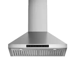
Model Name: RB10
Available Sizes: 30" 36"


TABLE OF CONTENTS
Important Safety lnstructions ........................................................... 2
Electrical Requirements
.................................................................. .4
Venting Requirements
..................................................................... 5
Calculating Vent System Length, Specifcations
.............................. 6
Required Tools ................................................................................. 6
Parts Supplied .................................................................................. 8
Dimensions ...................................................................................... 9
Preparation ...................................................................................... 10
Do's and Don'ts for Duct Venting ..................................................... 10
Rough-in ......................................................................................... 11
lnstallation ....................................................................................... 12
Charcoal Filters ............................................................................... 14
Filters .............................................................................................. 15
Venting Methods ............................................................................. 16
Range Hood Operations (Digital Panel) .......................................... 17
Explosion Diagram .......................................................................... 18
Troubleshooting ............................................................................... 19
Maintenance .................................................................................... 20
Control Panel Replacement & Wiring Diagram ............................... 21
Bulb Replacement. .......................................................................... 22
Grease Replacement. ..................................................................... 23
Warranty ......................................................................................... 24
Disclaimer & Contact Us ................................................................. 25
FAQ ................................................................................................. 26
•
• fi fi
fi
•
•
•
• fl fi
•
•
•
• fi
•
• fl
IMPORTANT SAFETY INSTRUCTIONS
2
•
IMPORTANT SAFETY INSTRUCTIONS
•
•
•
•
•
•
•
•
•
fl
•
•
3
4

VENTING REQUIREMENTS
For the most
efficient
&
quiet operation:
•
A
distance of 24" to
30" is
recommended* between stove
top and the bottom of
range hood.
•
It is recommended that the range hood be vented vertically through the roof
through 6" or bigger round metal/aluminum duct work.
•
The size of the duct should be uniform.
•
Use no more than
three 90
°
elbows.
•
Make sure there is a minimum of 24" (61 cm) of straight duct between the elbows
if more than one elbow is used.
•
DO NOT install two elbows together.
•
The length of duct system and number of elbows should be kept to a minimum to
provide efficient performance.
•
The duct system must have a damper. If roof or wall cap has a damper, DO NOT
use damper (if
supplied) on top
of the range
hood.
•
Use aluminum foil tape to seal all joints in the duct system.
•
Use caulking to seal exterior wall or roof opening around the cap.
USE 6" ROUND ROOF OR RECTANGULAR WALL VENT CAP.
IMPORTANT:
•
Use a rectangular to circular transition to connect range hood to ducting system.
•
A minimum of
a
6" round duct (standard for
this
range
hood)
must be
used
to
maintain maximum airflow efficiency.
•
Always use rigid type metal/aluminum ducts if available to maximize airflow when
connecting to provided duct.
•
Please use Duct Run Calculation below to compute total available duct run when
using elbows, transitions and caps.
•
ALWAYS, when possible, reduce the number or transitions and turns in the duct run.
If a reducer is used, install a long reducer instead of a pancake reducer.
Reducing the duct size will restrict airflow and decrease efficiency.
•
If turns or transitions are required: Install as far away from opening and as far apart,
between 2, as possible.
•
Minimum mount height between stove top to hood bottom should be no less than 24".
•
Maximum mount height between stove top to hood bottom should be no higher than
30".
•
It is important to install the hood at the proper mounting height. Hoods mounted too low
could result in heat damage and fire hazard; while hoods mounted too high will be hard
to reach and will loose its performance and efficiency.
•
If available, also refer to stove top manufacturer's height clearance requirements and
recommended hood mounting height above range.
Minimum Duct Size:
•
Round -
6" (use
Aluminimum foil
tape
to
properly seal)
•
Due to different ceiling height configurations, recommended height may not be applicable.
5
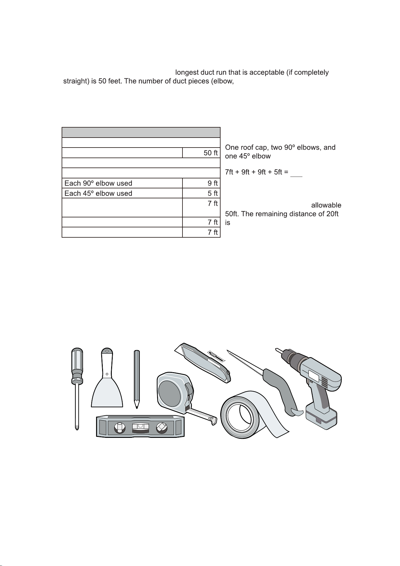
Putty
Knife
Pencil
Tape
Measure
Phillips
Screwdriver
Aluminum Tape
Power
Drill
UtilityKnife
Drywall Knife
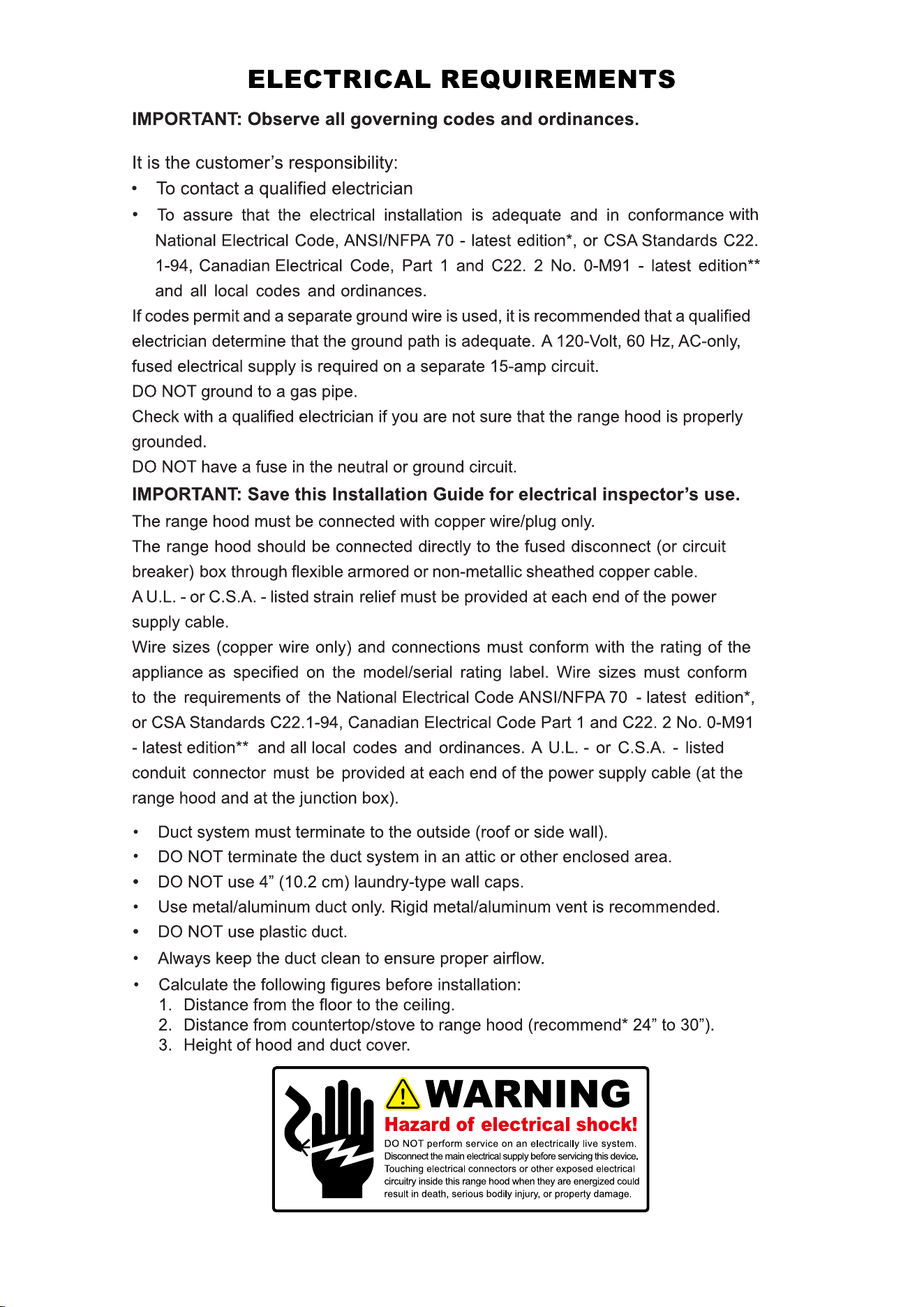
To calculate the length of the duct system you require, subtract the equivalent feet
for each “Duct piece” (Table Below) used in the system from the “Recommended
maximum run” (Table Below). The
transition, etc.) installed in
your duct run will determine the maximum length the duct run can be. Please refer
to the example below:
Duct Run Calculation:
Recommended maximum run
6” round duct
Duct piece deduction
Each round to rectangle transition
used
Side wall cap with damper
Roof cap
Duct Run Calcuation example:
used:
30ft
used.
The above duct pieces used are
equivalent to 30ft of a straight duct
run. Subtract 30ft from the
the longest that the straight ducting
(in addition to the vent pieces) can be.
CALCULATING VENT SYSTEM LENGTH
REQUIRED TOOLS
Level
6
SPECIFICATIONS
RB10
Stainless Steel
120V/60Hz (USA & Canada standard)
130W + 4W for LED Lights
130W
850 RPM (±10%) to 1200 RPM (±10%)
3 Levels
180 Pa (200 Pa Maximum)
1.0 Sone (40 dB)/ 4.0 Sone (55 dB)/ 6.5 Sone (60 dB)
B
Model Name
ody
Power Rating
General
Input Power
Motor Input Power
Motor Revolution
Levels Of Speed Control
Air
Pressure
Noise Level (Q/M/H)
Motor Type
Power Connection
Type
Control Type
Filtration Type
Single Mot
Venting
Illumination
Size
Warranty
or
Plug-in Wire (120V)
Digital Display Panel
Aluminum Filters
1.2
Top 6"
2 x 1.5W LED (4000K)
Round
2 Year Parts Warranty
A
General Input Current
7
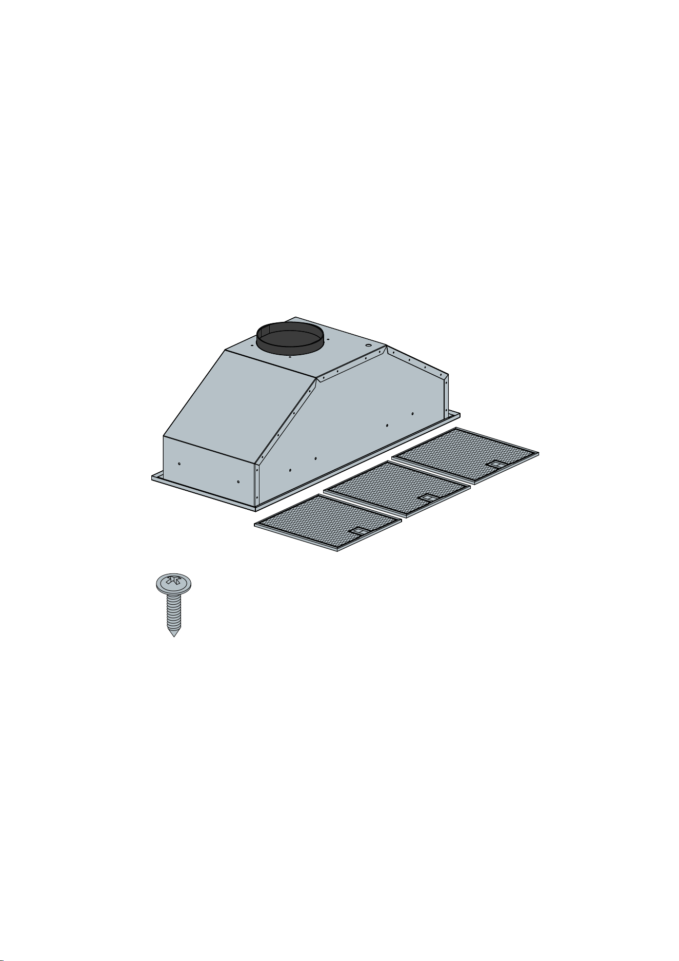
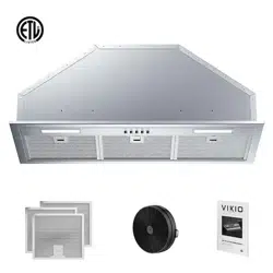
NOTE:
Where necessary, additional screws will be needed for installation and added
support, but is not included. Please review contents before installation.
RB10-PARTS SUPPLIED
QTY: 12 PCS
Anchor Screw
(M4x16mm)
8
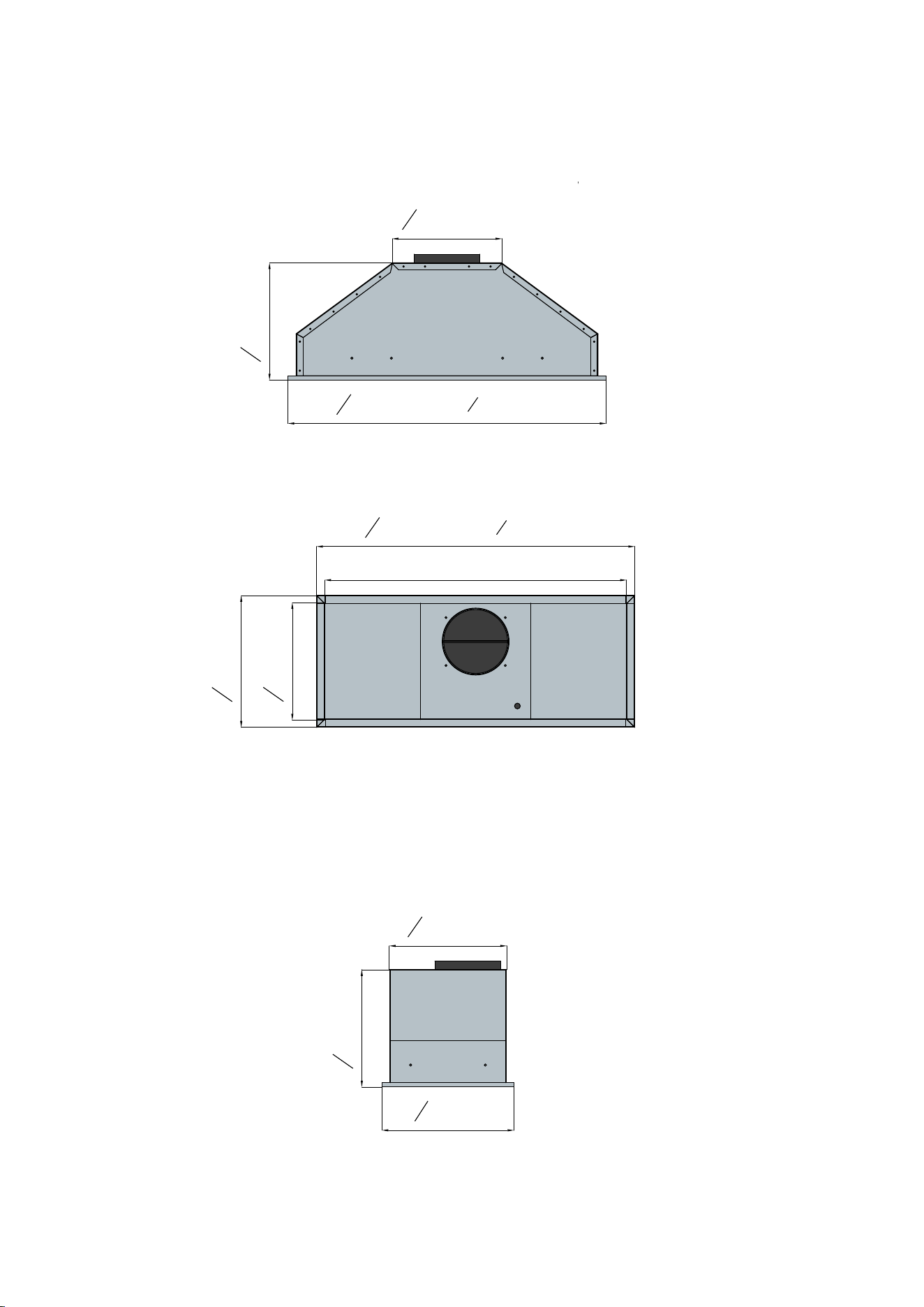
TOP VIEW
DIMENSIONS
FRONT VIEW
SIDE VIEW
28
1
2
" [724mm] / 35
7
16
"[900mm]
11
13
16
" [300mm]
10
1
2
" [267mm]
27" [686mm] / 34"[864mm]
9
13
16
" [250mm]
10
1
2
" [267mm]
28
1
2
" [724mm] / 35
7
16
"[900mm]
11
13
16
" [300mm]
10
1
2
" [267mm]
10
1
2
" [267mm]
9
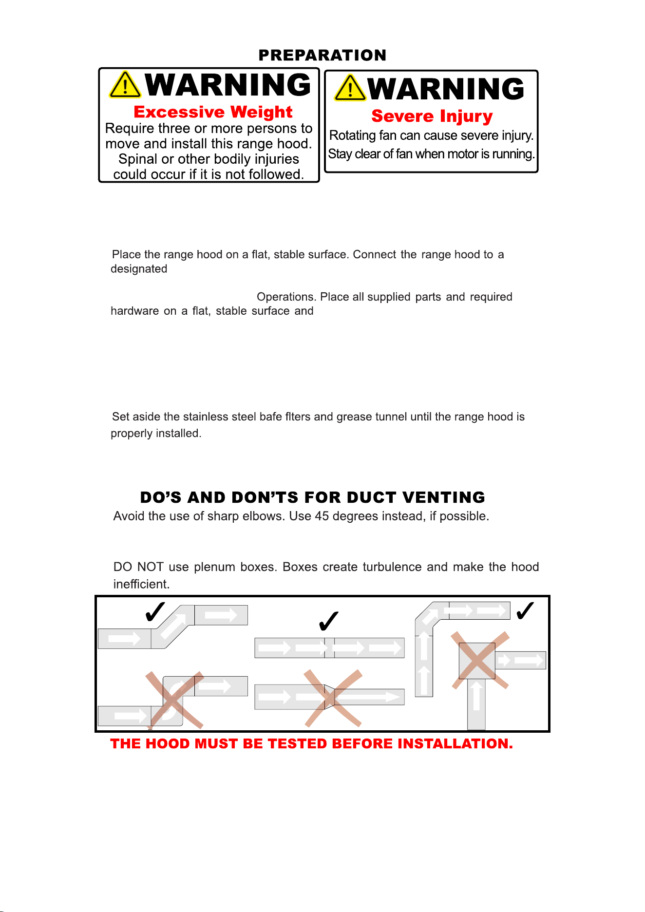
Advanced Preparations:
•
Be familiar with the controls of the range hood by reading through Range
Hood
Operations.
•
standard outlet (please refer the product label for the suitable voltage
of this unit) and turn on the range hood. Verify all operations of the range hood
by referring to Range Hood
verify the existence of all supplied parts.
• Carefully remove the white or blue plastic protective coat from the range hood.
Preparations:
NOTE: To avoid damage to your hood, prevent debris from entering
the vent opening.
•
Disconnect power cord, remove the stainless steel bafe flter and grease tunnel.
•
Vikio will not be responsible for additional labour costs related to
reinstallation of the hood due to transportation internal damage or wiring issues.
(a)
(b)
(c)
the manual. Areducer will reduce the CFM of the hood and increase the noise.
c.
Use a smooth elbow to guide the air outdoors.
a.
b. DO NOT use REDUCERS. Keep the size of the duct the same, as per
10
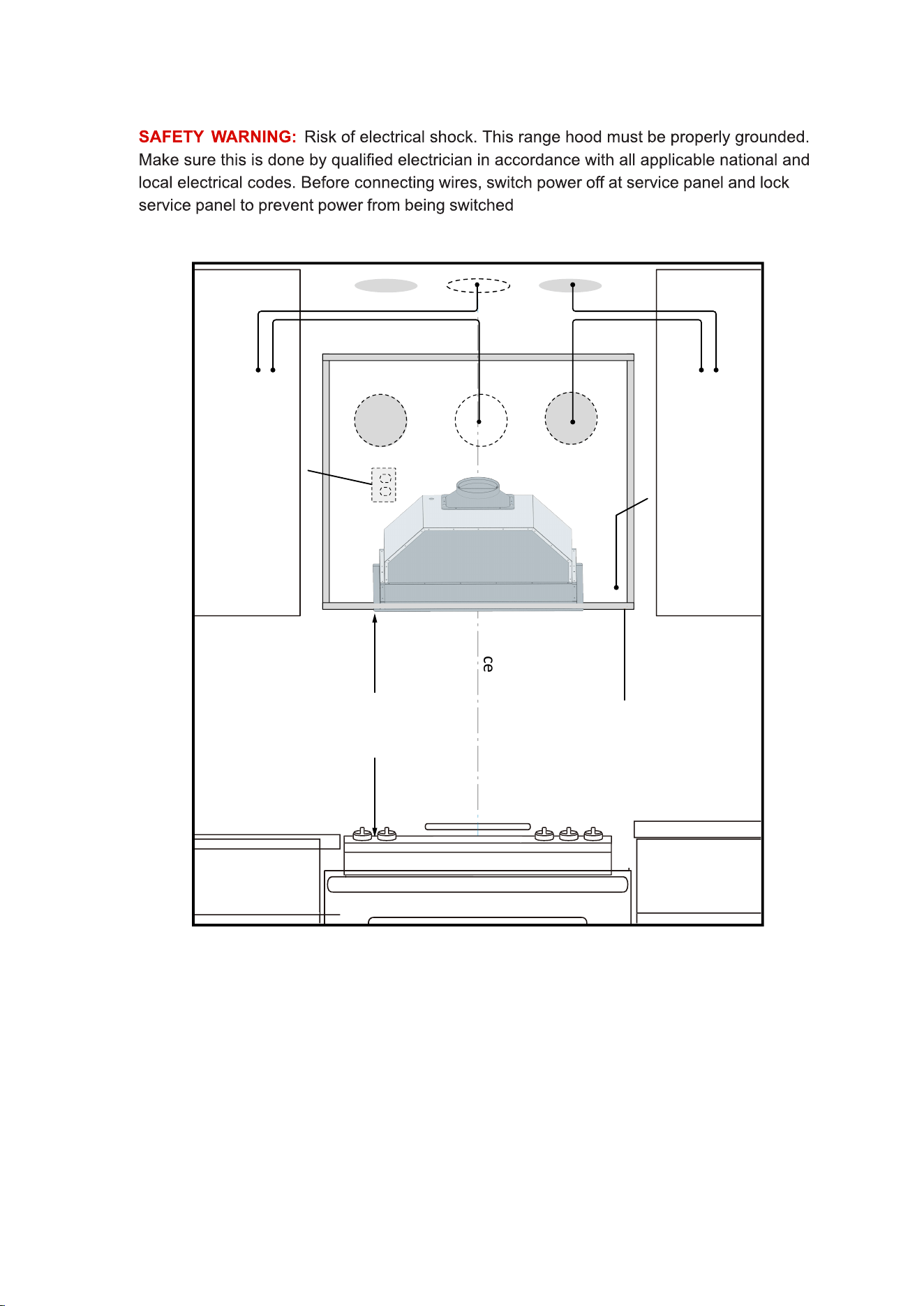
ROUGH-IN
center line
Max: 30”
Min: 24”
Optimal: 28”
Preferred areas to
install wall or roof
vent ducting
Allow spacing for
wood blocking
to bottom panel
Wall or roof vent
may be installed
in these areas but
not recommended
Cabinet surround should
accommodate the bottom
lip of the range hood
120v Outlet can
be located here
Side Cabinet Side Cabinet
Cooking Surface
Ceiling
on accidentally.
11
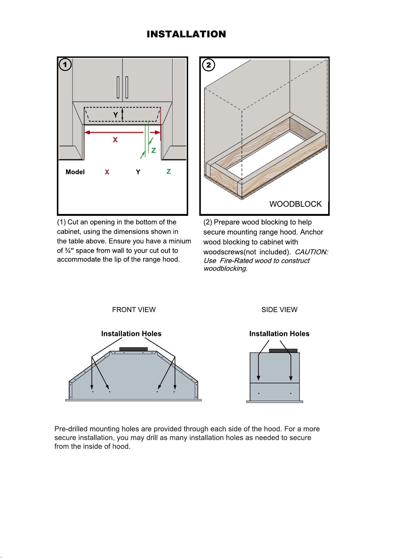
RB10-30 27⅜" 10⅞" Min.¾"
34⅜" 10⅞" Min.¾"RB10-36
12
INSTALLATION (Continued)
SAFETY WARNING: Risk of electrical shock. This range hood must be properly
grounded. Make sure this is done by qualifed electrician in accordance with all
applicable national and local electrical codes. Before connecting wires, switch
power of at service panel and lock service panel to preduct power from being
switched on accidentally.
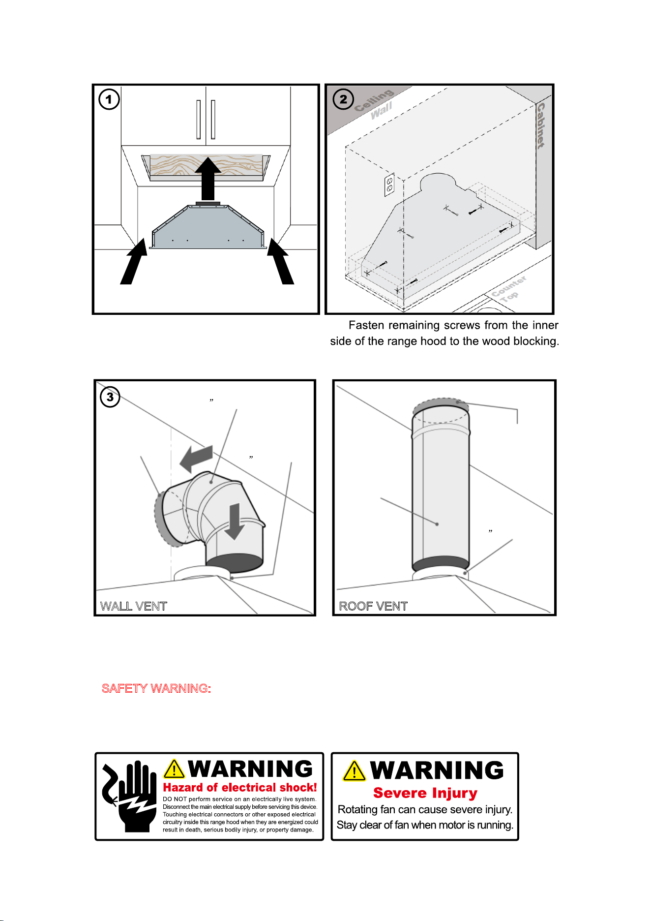
(3) Carefully insert and slide the range
(4)
hood in the overhead cabinet.
6
Cut out hole on
the top panel of
cabinet, and in
ceiling for
6”
6
6
Cut out hole
in wall to
accommodate
elbow duct.
- Ø Transition
- Ø Elbow Duct
- Ø Duct
exhaust duct
- Ø Transition
WALL VENT
ROOF VENT
Use 6" round steel pipe to connect the
exhaust on the hood to the duct work above.
Use aluminum tape to make all joints secure
(3) Distance from wall to transition
circumference edge for 6".
and air tight.
13
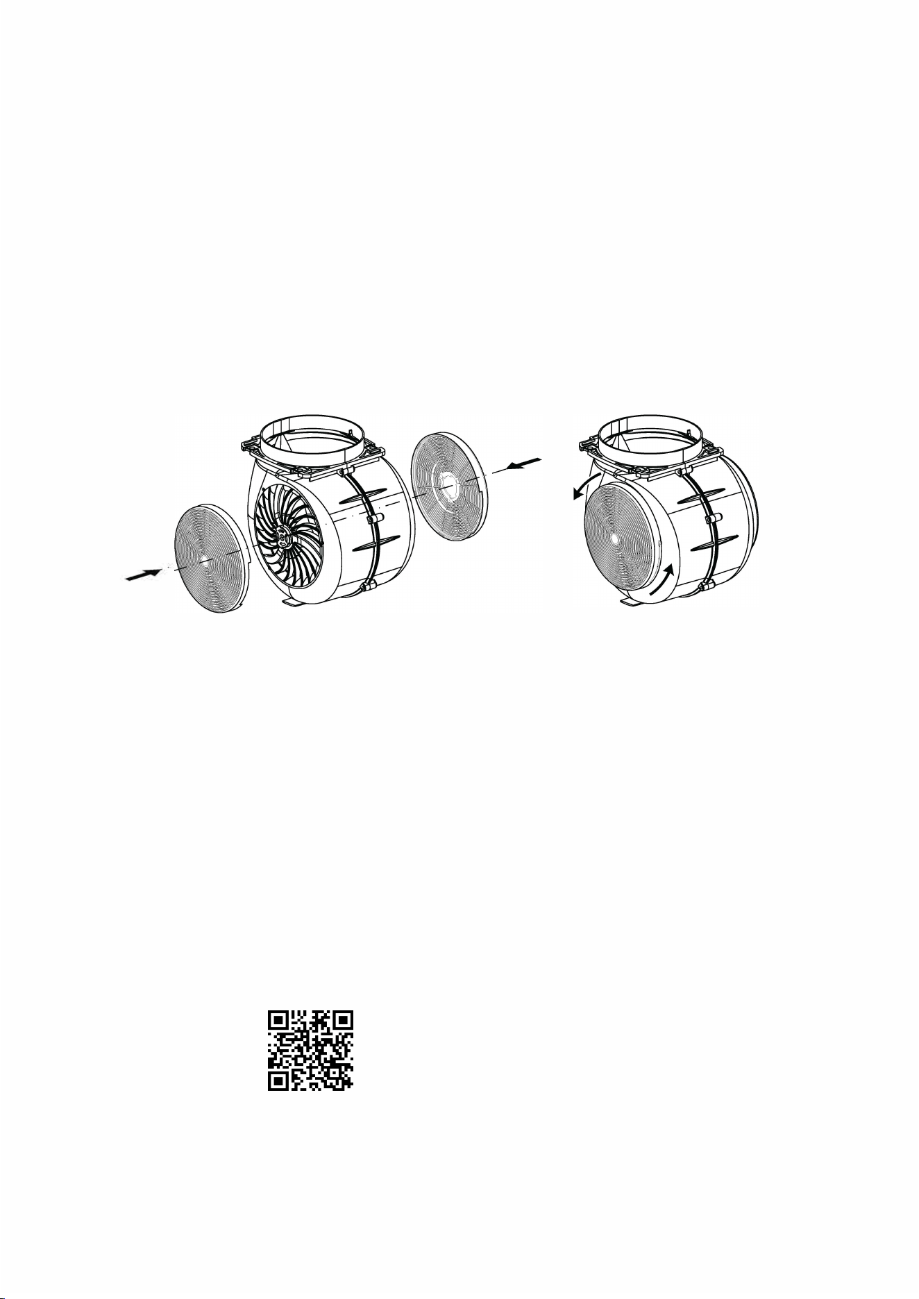
If you need to do a ductless installation, please follow the
installation steps without installing a smoke pipe. And
install the activated carbon.
HOW TO REPLACE
OR
CHANGE
CHARCOAL FILTERS
It is recommended to use ducting to direct vent your range hood whenever possible.
If
you have a recirculating kit installed on your under cabinet hood, carbon charcoal flters
are available to recirculate the air through your hood.
Scan for a charcoal filter
installation tutorial video
Replacing Char.
14
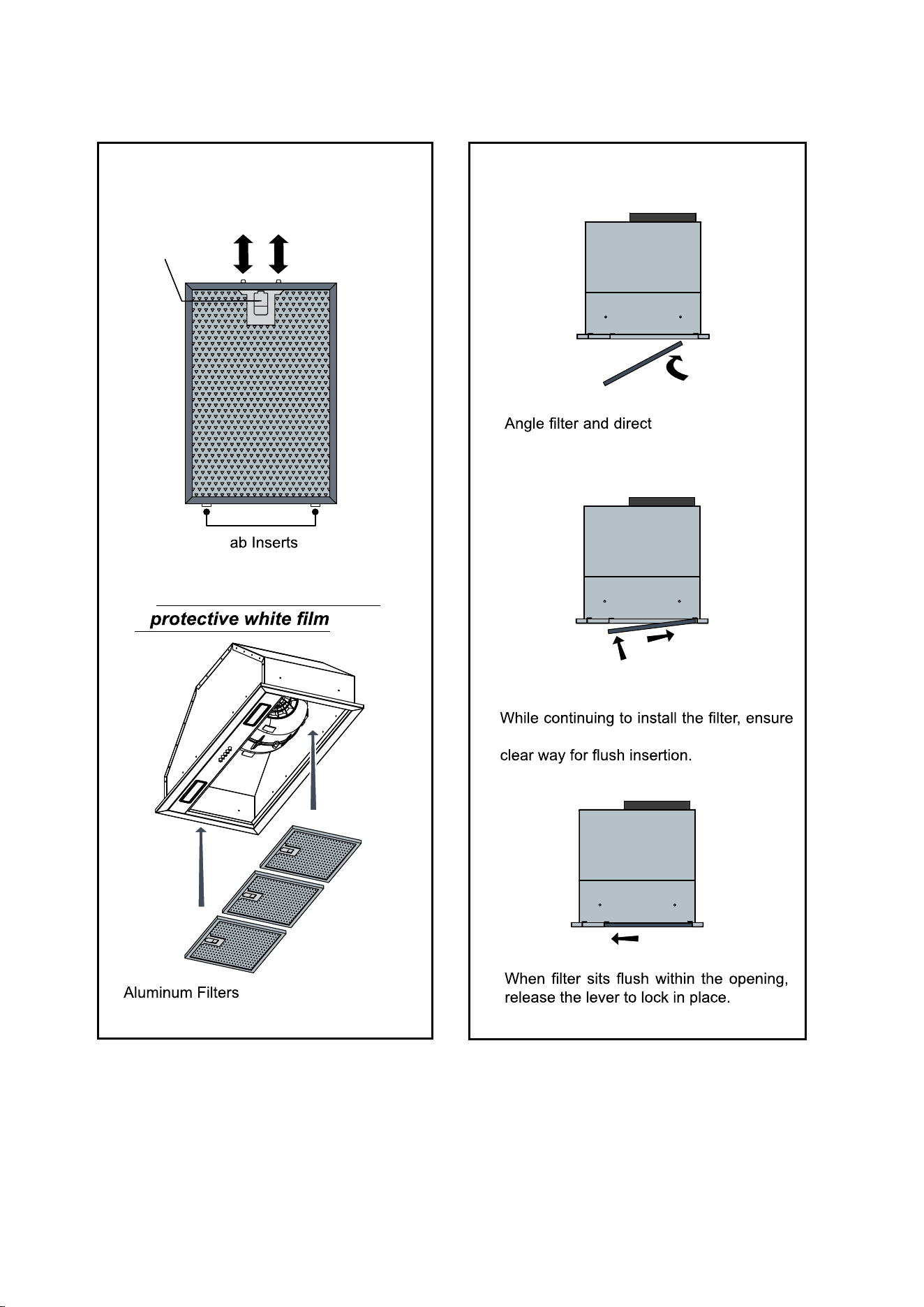
Retractable Tabs
BOTTOM VIEW
SIDE VIEW
you lift the lever for the retractable tabs to
tab inserts toward
the aft slot of the
range hood opening.
INSTALLATION OF FILTERS
T
Lift Lever
***Before installing, remove
***
15
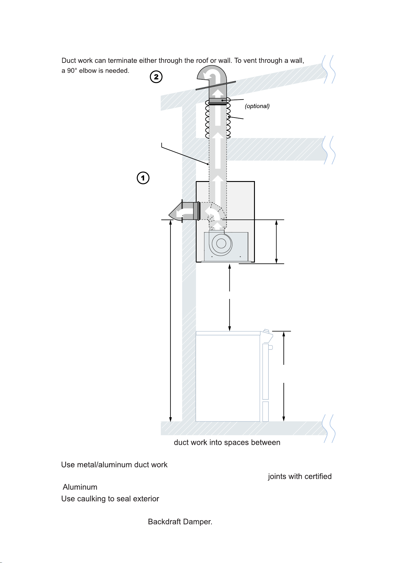
VENTING METHODS
Backdraft Damper
Wrap insulation
required for
cold climates
Minimum
6” Ø Duct
Wall
Vent
Roof
Vent
36”
typical
Min: 24” Max: 30”
17
½”
*Min height: 77 ½”
f
rom bottom of duct
to ground when range
height to stove is 24”
Min height: 83 ½”
from bottom of duct
to ground when range
height to stove is 30”
•
This range hood is factory set for venting through the roof or wall.
•
IMPORTANT:
• NEVER exhaust air or terminate walls, crawl
spaces, ceiling, attics or garages. All exhaust must be vented to the outside.
•
only.
•
Fasten all connections with sheet metal screws and tape all
Tape.
•
wall or roof opening around the cap.
• Colder climates require wrapping insulation around the ducts and optional blowers.
•
The system must have a
16
Motor
16
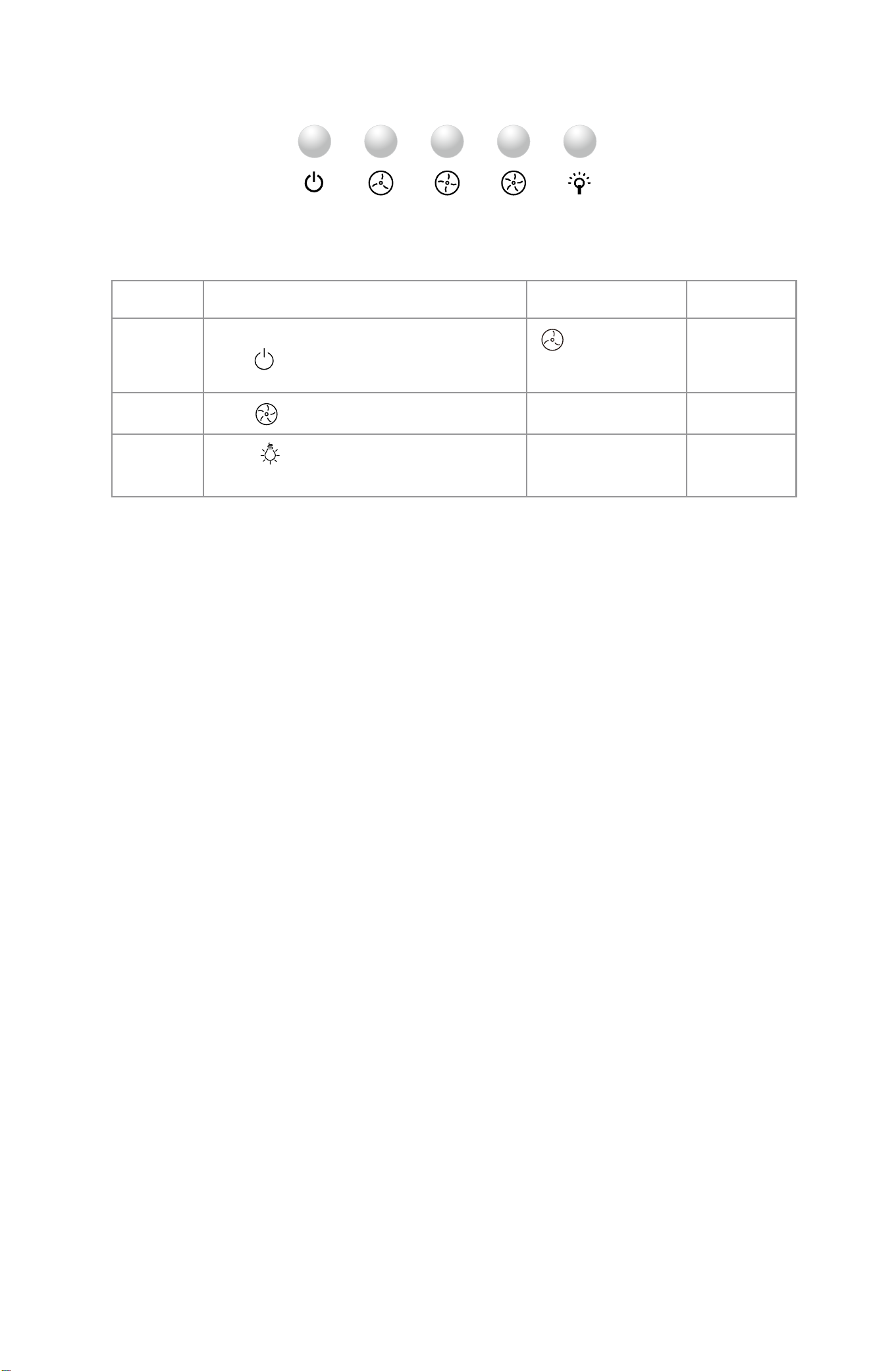
RANGE HOOD OPERATIO
NS (Mechanical)
FUNCTION
OPERATION
INDICATE
REMARK
Press Power button to turn off the systerm.
OFF
SPEED
LightPower Speed setting
Press Speed button to choose the speed.
LIGHT
Press Light button to turn on or off the
lighting function.
LED lights are
individually
controlled
When the switch is off,
the speed off.
17
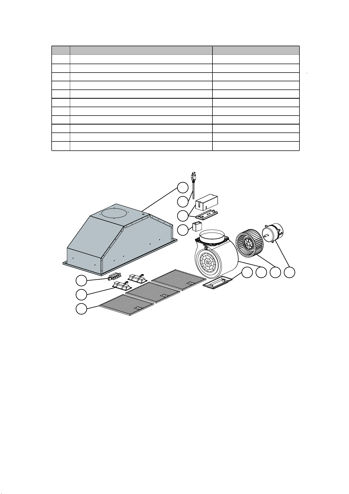
RB10-EXPLOSION DAGRAM
No. Description
Quantity
1
2
3
4
5
6
7
8
Grease Cup
9
Hood Body
Control Panel
Light10
11
Spuirrel Cage
Fan Blade
Motor
Capacaitor
1
Plastic box
1
1
1
1
1
1
1
2
1
3
Power Cord
Aluminum Filter
1
2
3
4
7
6
5
8
9
10
11
18
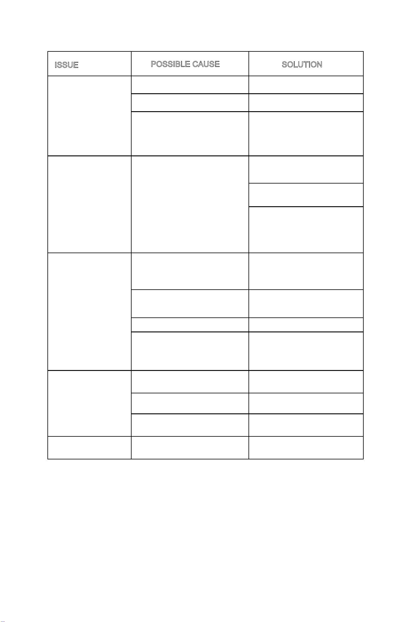
TROUBLESHOOTING
POSSIBLE CAUSE
ISSUE
The blower or fan seems
A large amount of oil has
accumulated on the baffle filter.
weak.
SOLUTION
Use the wrong duct size.
The distance between the range
hood and the stove is too far.
The duct is clogged or if damper
unit(half-circular flapper) is not
installed correctly.
Range hood is making a
Check that there is power to the
range hood.
rattling noise.
The motor is loose.
The duct work connection is loose.
The hood is not secured in place.
The motor is working, the
light is not on.
The light connector is not connected
The lights cannot be
turned off
The circuit or switch board is out of
order.
Light out of order
.
Range hood does not
work.
The circuit board is out of order.
Turn off the power and check that
all wires are properly connected.
Refer to your specific model's
installation instructions for proper
wiring.
Turn off the power and remove
the filter and check that all screws
are secure and tight around the
motor.
The ductwork connection to the
pipe is tight. Add duct tape if
necessary.
Check the installation of the hood.
If it is stuck, it will sound like motor
Clean or replace the baffle filters.
Use the right duct- 3-1/4x10" or
6" round type.
Adjust the distance between the
range hood and the stove top
Clear the blockage of the duct.
Install the flapper correctly.
The most common issue is that
the circuit breaker is off or the
fuse has blown.
Make sure the speed has been
selected at the controls.
noise but it's really the damper.
Check whether the air outlet is
blocked by foreign matter or air
duct deformation, and the
damper is opened normally.
Check whether the LED
connector is connected
Contact customer service to
replace the lamp.
Contact customer service to eplace
the switch board or circuit board.
Contact customer service to
replace the circuit board
19
19
•
20
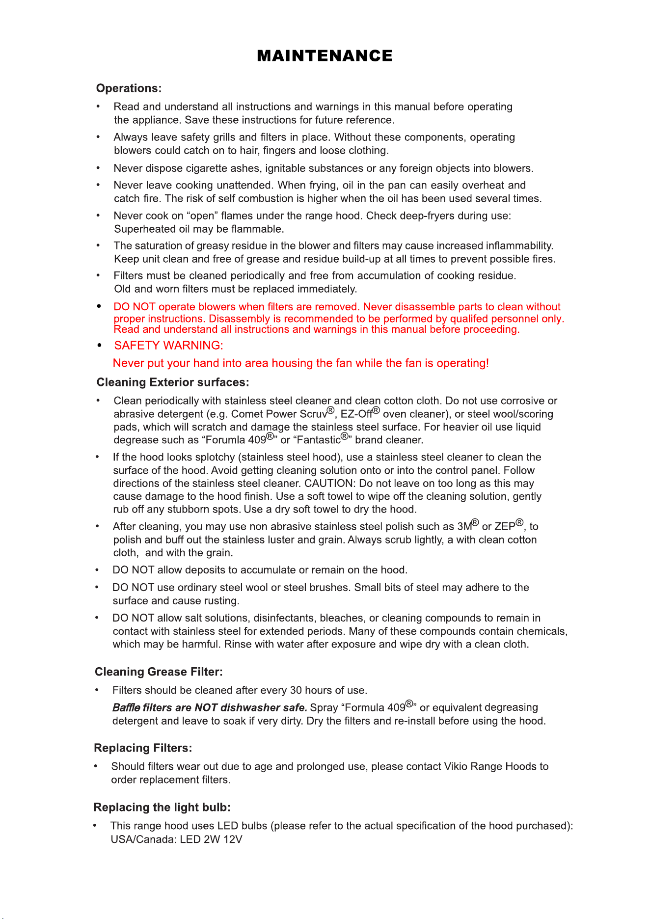
CONTROL PANEL REPLACEMENT
Replacing Control Panel:
3. Remove the screws on the LED Light panel.
5. Fix the screws holding the control panel.
Fix the screws of LED Light panel.
WIRING DIAGRAM
Never work on or clean the range hood while the power is on.
W
ARNING
Always unplug the unit or switch the electrical breaker to the off position.
Scan for a button panel installat
ion tutorial video.
M~
M~
5μF/250V
C
5μF/250V
C
120V~
2×Max 2W
70W
70W
KL
K10
K1
K2
K3
21
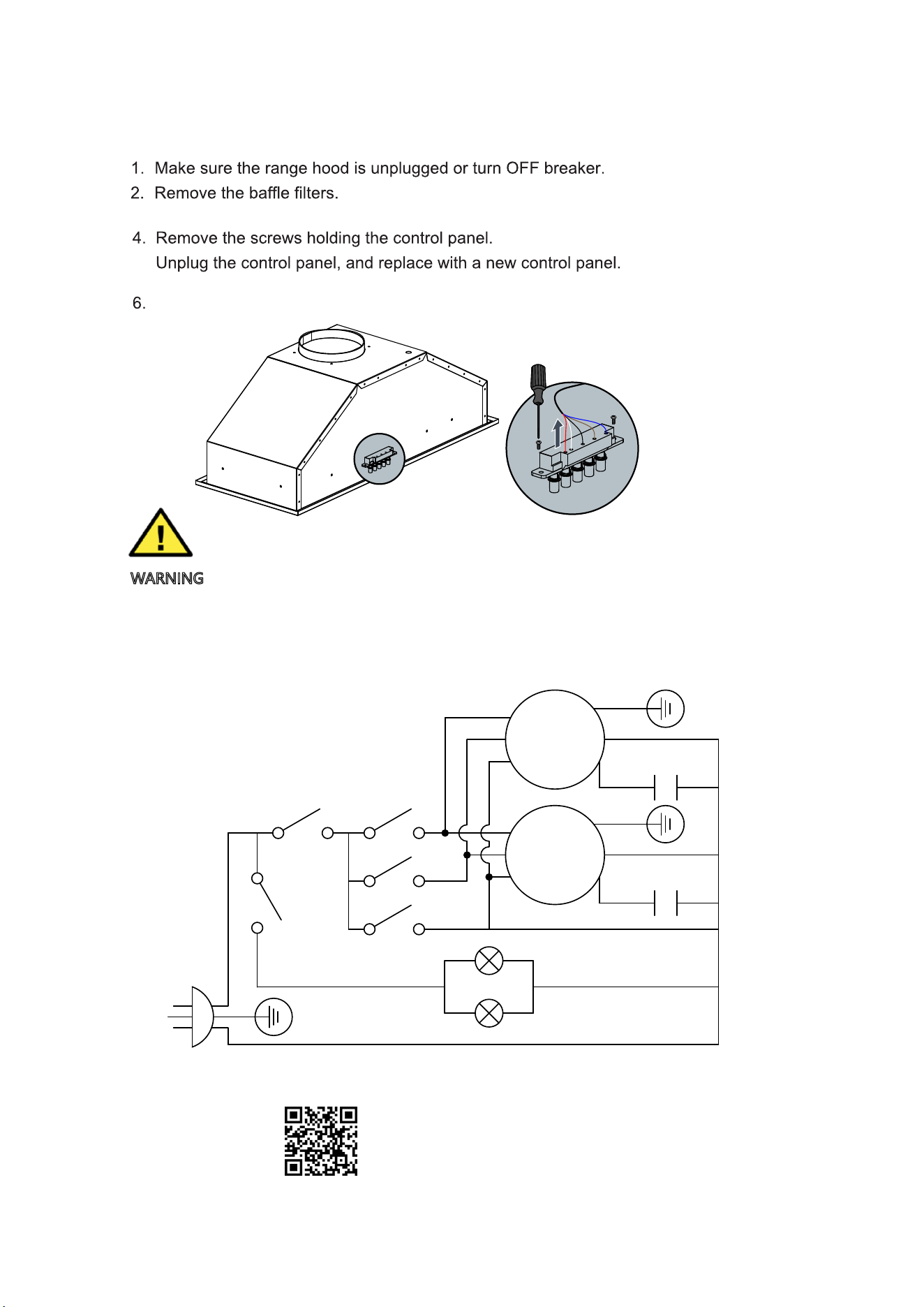
Replacing
LED 2W Light Fixture:
RB10-BULB REPLACEMENT
Scan for a light bulb
installation tutorial video.
22
WARNING
Never work on or clean the range hood while the power is on.
Always unplug the unit or switch the electrical breaker to the
off position.
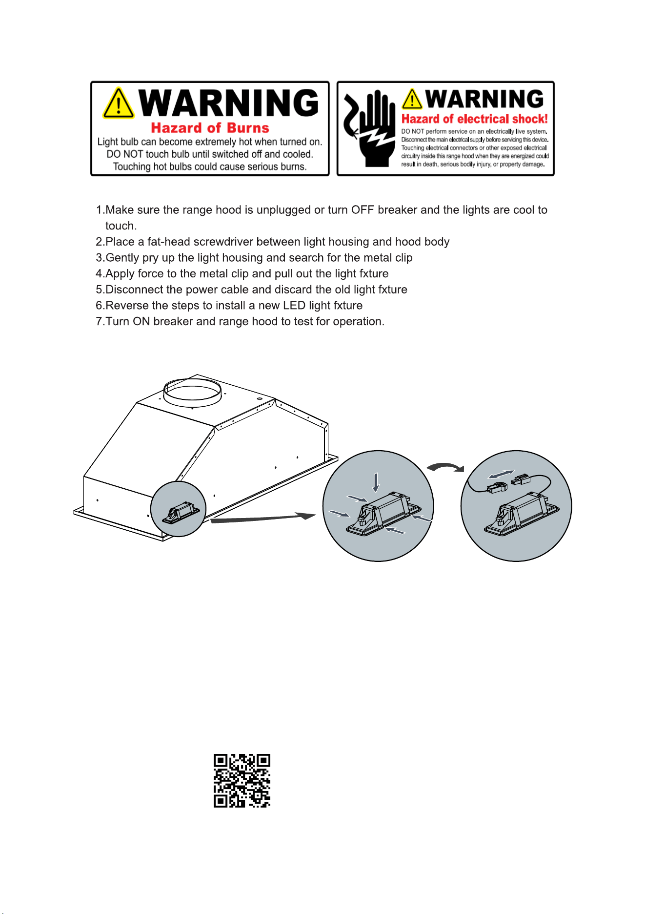
32
Slide into place
23
1
General Safety
TO OBTAIN SERVICE UNDER WARRANTY:
You must present proof of original purchase date.
WARRANTY
Year Parts Warranty:
For year from the date of original purchase, Vikio Range Hoods will provide free of
materials.
Replacement parts or products will be provided by Vikio Range Hoods on an exchange basis,
and will be either new or refurbished to be functionally equivalent to new.
This Warranty Will Be Voided When:
Product is damaged through negligence, improper installation, accident, abuse, misuse,
follow installation
instructions. When product is used commercially or other than its intended purpose. Damaged
because of improper connection with equipment of other manufacturers.
Who is Covered:
This warranty is extended to the original purchaser for products purchased for ordinary
home use.
What is Not Covered:
and
wear due to improper maintenance, use of corrosive and abrasive cleaning products,
acts of God. The
manufacturer and/or distributor/reseller is not liable for, and does not cover under warranty, any
loss of properties or any costs associated with removing
, servicing, installing, or determining
the source of problems with this product.
applies only to the original purchaser and does not extend to subsequent owners of this product.
Any applicable implied warranties, including the warranty of merchantability, are limited in
duration to a period of express warranty as provided herein beginning with the date of original
purchase and, no
warranties, whether expressed or implied, shall apply to this product thereafter.
of
Vikio Range Hood’s policies prior to contacting us. Typically, you must include product
problem you are experiencing. You must also include proof of the date of original purchase as
evidence that the product is within the applicable warranty period, and that it isagenuine range
hood from Vikio
Range Hoods.
kio
24
2
info@ vikiohome.com www.vikiohome.com
25
26


info@ vikiohome.com
www.vikiohome.com