WARNING:
TO AVOID RISK OF ELECTRICAL SHOCK, BE SURE TO SHUT OFF
POWER BEFORE INSTALLING OR SERVICING THIS FIXTURE.
NOTES: 1. Before installing, consult local electrical codes for wiring and grounding requirements.
2. Read and save these instructions.
ASSEMBLY AND INSTALLATION
INSTRUCTIONS
LK33053WP
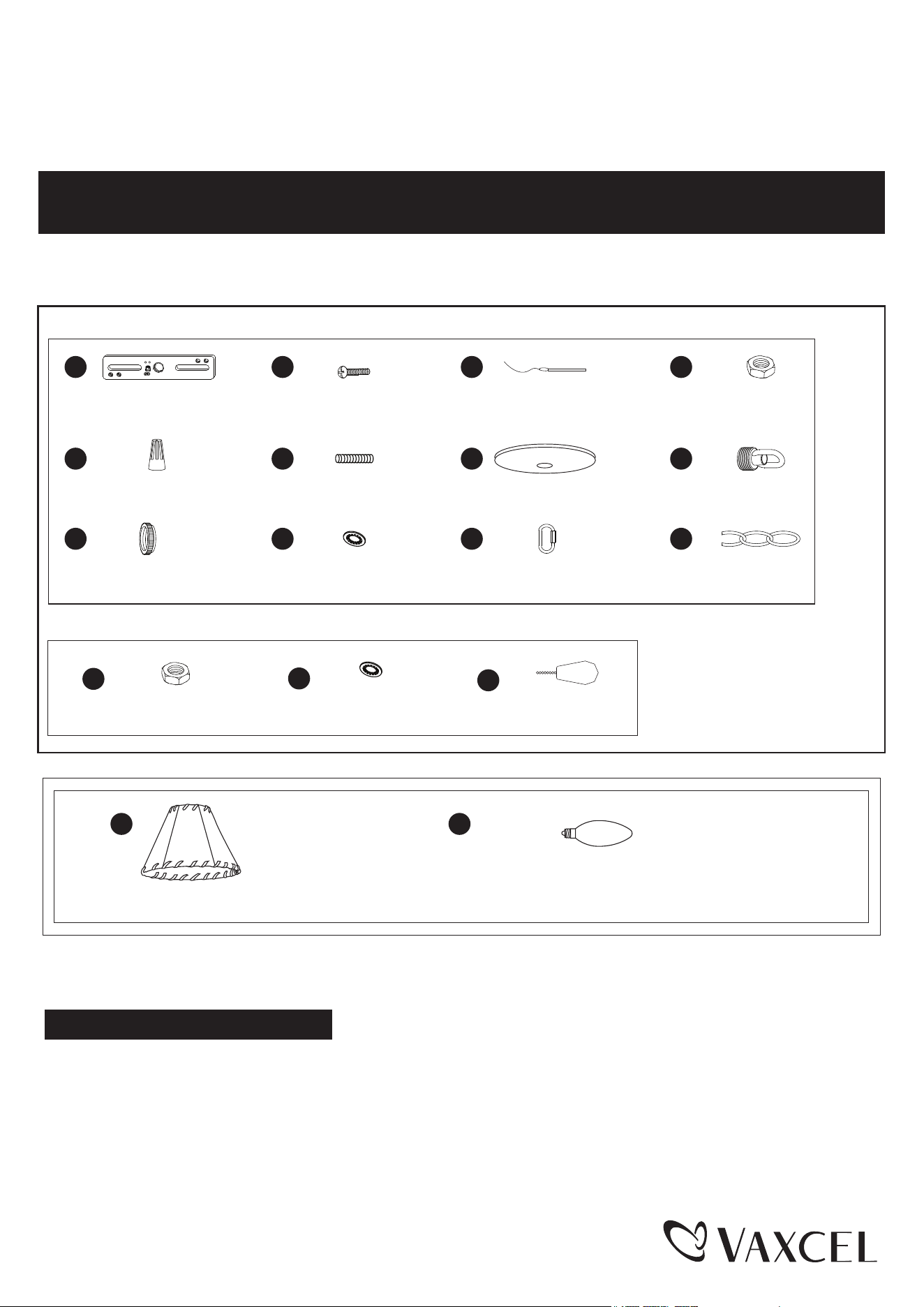
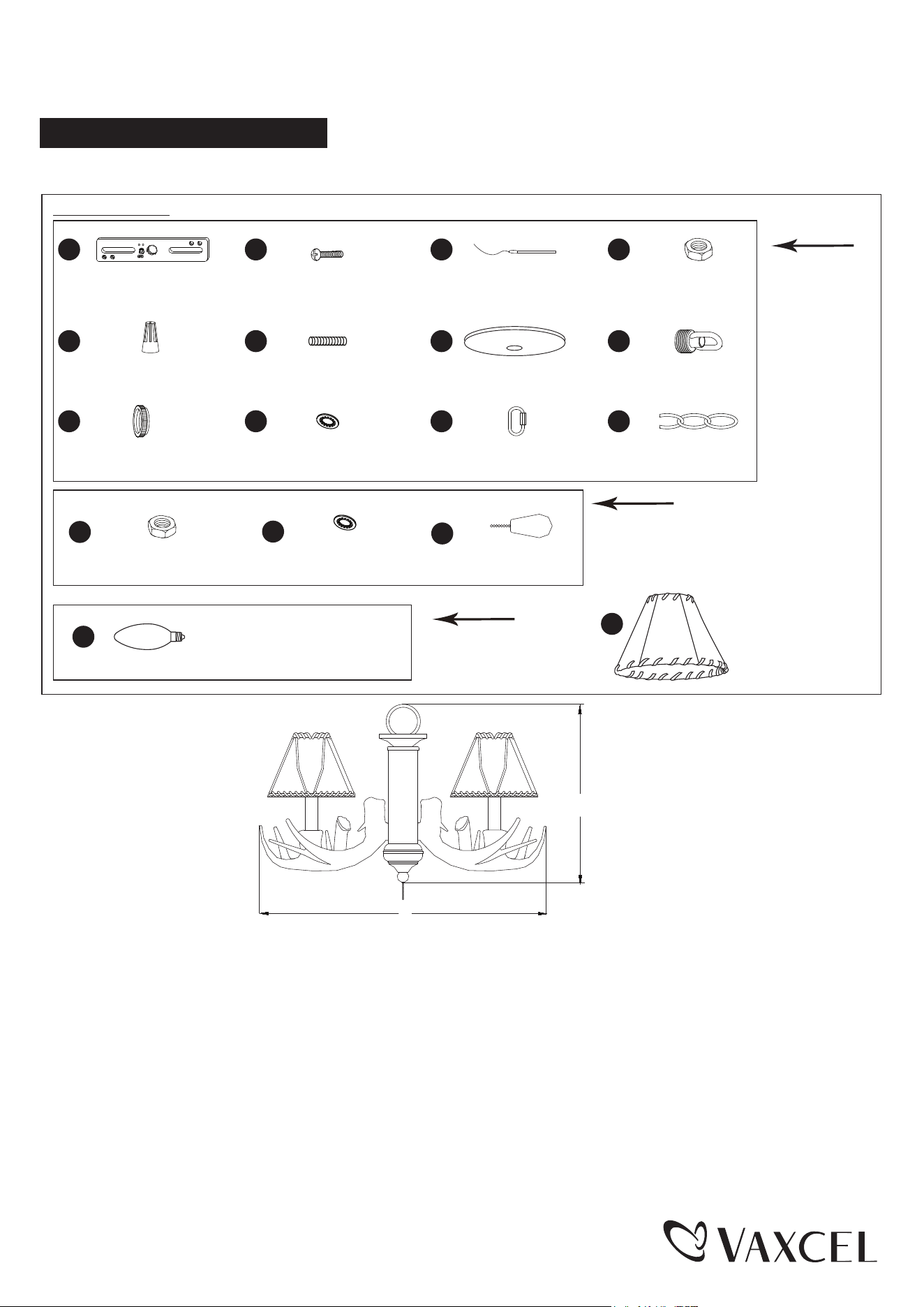
Hardware Package (included): For Mini Chandelier
AA
BB
CC DD
Mounting Strap
X1
Mounting Screw
X2
Fixture Ground Wire
X1
Hex Nut
X1
EE
II
FF
JJ
GG
KK
HH
LL
Wire Connector
X3
Canopy
X1
Top Loop
X1
Collar
X1
Threaded Pipe
X1
Washer
X1
Loop Lock
X2
Chain
X1
Turn off the power at fuse or circuit box.
Installation Steps
For Light Kit:
For Fan Light Kit
Wood Bead
X1
Hex Nut
X1
MM
NN
OO
Washer
X1
A
Faux Rawhide Shade
X3
B
LED Bulb 4W Candelabra Base
2700K Dimmable 90CRI (included) X3
1. Unscrew the three screws from the fan and remove the switch box cover and wire connectors.
2. Adjust the cord of fan light kit (B) to 6 in. Cut the excess cord, peel off the insulation from the wire end about 3/8 in.
to expose the copper wires.
3. Feed the two wires from the fan light kit (B) through the center hole in the switch box cover, and thread the wires
through the washer (NN) and hex nut (MM). Then secure switch box cover onto the fan light kit (B) with a hex nut (MM)
and washer (NN).
Page 1 / 3
240702
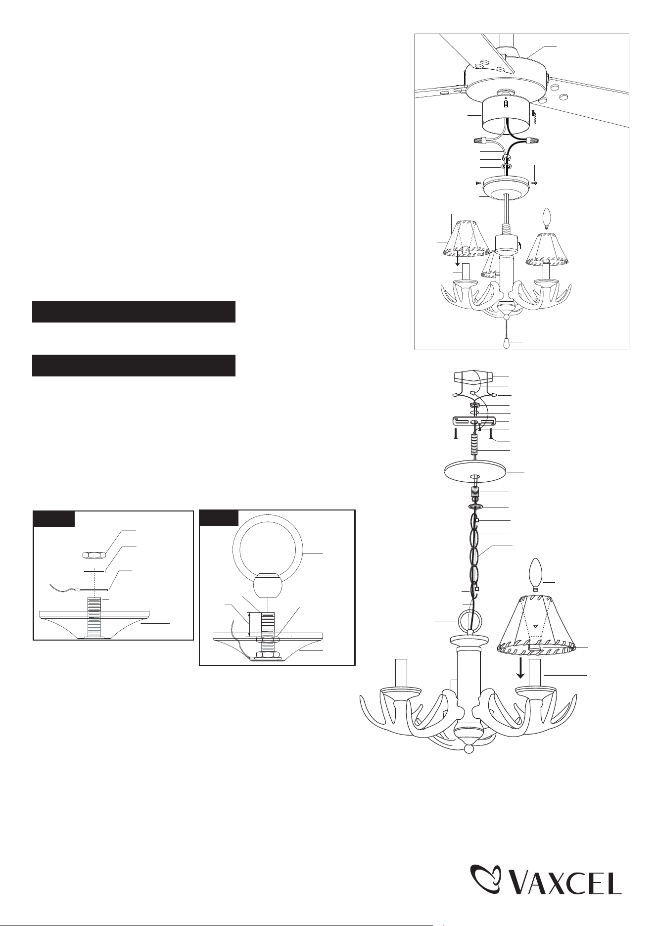
4. Connect wires with wire connectors (EE):
---Connect the blue wire (hot wire) from the switch box to the smooth wire
(marked) from the fan light kit (B).
---Connect the white wire (neutral wire) from the switch box to the ridged
wire (unmarked) from the fan light kit (B).
---Carefully put wires back into the switch box. Restore the switch box
cover back to the switch box with the three screws.
Note: 1. If your fan has a fitter plate, you may also need to connect
the 9-pin connector from the fan to the 9-pin connector from
the switch housing. If your fan has two single-pin connectors
instead of bare wires, it will be necessary to cut the wire
very close to the single-pin connectors and strip 1/2” of i
nsulation from the end of the two wires in order to connect
the fan wires to the wires from the fan light kit.
2. Do not cut the wires to the 9-pin connectors.
5. Attach the clips of the shades (A) onto the candle tubes. Install 3 LED
bulbs (C) (included). Attach the wood bead (OO) to the pull chain.
Note:Refer to the label on the lamp socket for Max Wattage
information.
Turn on the power at fuse or circuit box.
Turn off the power at fuse or circuit box.
For Mini Chandelier:
1. Install the mounting strap (AA). Attach threaded pipe (FF) to the
mounting strap (AA), and secure with a washer (JJ) and a hex nut (DD).
Attach the mounting strap (AA) to the outlet box using two mounting screws (BB).
2. Install the loop on the fixture. Unscrew the hex nut (DD) and
washer (JJ) out of light kit threaded pipe (FF). Install the ground
wire tab (CC) in light kit threaded pipe (FF), then secure the hex
nut (DD) and washer (JJ) back.Thread the fixture wire through the
hex nut (DD) and loop, then secure the hex nut (DD) and loop.
Motor
Switch Box
Switch Box Cover
Faux Rawhide Shade (A)
Screw
Clip
Candle
Tube
Wood Bead (OO)
LED Bulb 4W
Candelabra Base
(included)
6 in.
Hex Nut (MM)
Wahser (NN)
Loop
Fixture Wire
Chain (LL)
Threaded Pipe-1 (FF)
Fixture Ground Wire
Collar (II)
Top Loop (HH)
Canopy (GG)
Mounting Screw (BB)
Mounting Strap (AA)
Green Ground Screw
Hex Nut (DD)
Wire Connector (EE)
Washer (JJ)
Outlet Box
Loop Lock (KK)
Loop Lock (KK)
House Ground Wire
Shade
Clip
Candle Tube
LED Bulb 4W
Candelabra Base
(included)
Fig.2-b
1/2"
Loop
Cap
Threaded
Pipe-1 (FF)
Hex Nut (DD)
Cap
Fig. 2-a
Hex Nut (DD)
Washer (JJ)
Fixture Ground
Wire (CC)
Threaded Pipe-1 (FF)
3. Attach the chain(LL). Adjust the fixture chain (LL) to the
desired length by moving the links if needed. You may
need to use pliers (not included) to open the chain links.
If so, put a cloth over the chain to protect the finish from
the pliers. Connect the fixture chain (LL) to the fixture
loop on the top of the column and the top loop(HH) using
the loop lock (KK).
Pull the power cord as well as ground wire up through the chain (LL), collar (II), top loop (HH), canopy (GG).
4. Connect the wires with wire connectors (EE). Push all slack fixture wires through the canopy (GG) and into the outlet box.
Trim the excess fixture wire, leaving a minimum of 6 in. hanging out of the outlet box. Connect the smooth wire (marked)
from the fixture to the black wire from the power source. Connect the ridged wire (unmarked) from the fixture to the white
wire from the power source. Loop the house ground wire around the green ground screw on the mounting strap (AA) and
tighten it in place. Wrap all wire connections with electrical tape for a more secure connection. Attach the canopy (GG)
to the mounting strap (AA) by inserting the top loop (HH) and secure with the collar (II).
Page 2 / 3
240702
Turn on the power at fuse or circuit box.
5. Attach the clips of the shades (A) onto the candle tubes. Install 3 LED bulbs (C) (included).
Attach the wood bead (OO) to the pull chain.
Note:Refer to the label on the lamp socket for Max Wattage information.
Spare Parts List:
Assembly Kit
4035MM (1 SET)
Assembly Kit
4035AA (1 SET)
Assembly Kit
X-BB12-4LED (3PCS)
Faux Rawhide Shade
57091 (3 PCS)
LED Bulb 4W Candelabra Base
(included)
2700K Dimmable 90CRI
8096LD
C
A
AA
BB
CC DD
Mounting Strap
X1
Mounting Screw
X2
Fixture Ground Wire
X1
Hex Nut
X1
EE
II
FF
JJ
GG
KK
HH
LL
Wire Connector
X3
Canopy
X1
Top Loop
X1
Collar
X1
Threaded Pipe
X1
Washer
X1
Loop Lock
X2
Chain
X1
Wood Bead
X1
Hex Nut
X1
MM
NN
OO
Washer
X1
The following parts are available for re-order if damaged or missing.
A
B
A : 19-1/2”
B: 10”
1 Year Warranty
How can warranty service be obtained?
1-800-482-9235
Vaxcel warrants all of our products against defects in workmanship and finishes for one year following the date of
shipment.
Exclusions: This warranty does not include the failure of products from extreme acts of nature; environmental conditions
not suited for the products intended use; operation in temperatures outside of the range specified in the instruction
manual; usage with improper power supply, power surges or dips. For coastal locations, some corrosion is considered
normal for the environment.
Vaxcel reserves the right to repair, replace or issue a credit for any properly installed product, provided it is returned per
RMA instruction. This warranty is limited to the cost of the product only and does not extend to transportation, installation
or replacement costs.
Page 3 / 3
240702