Questions, problems, missing parts? Before returning to your retailer, call our customer service
department at 1-833-695-2045, 8:30 a.m. - 5 p.m., EST, Monday - Friday.
30996-MNDC
355-0763
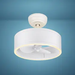
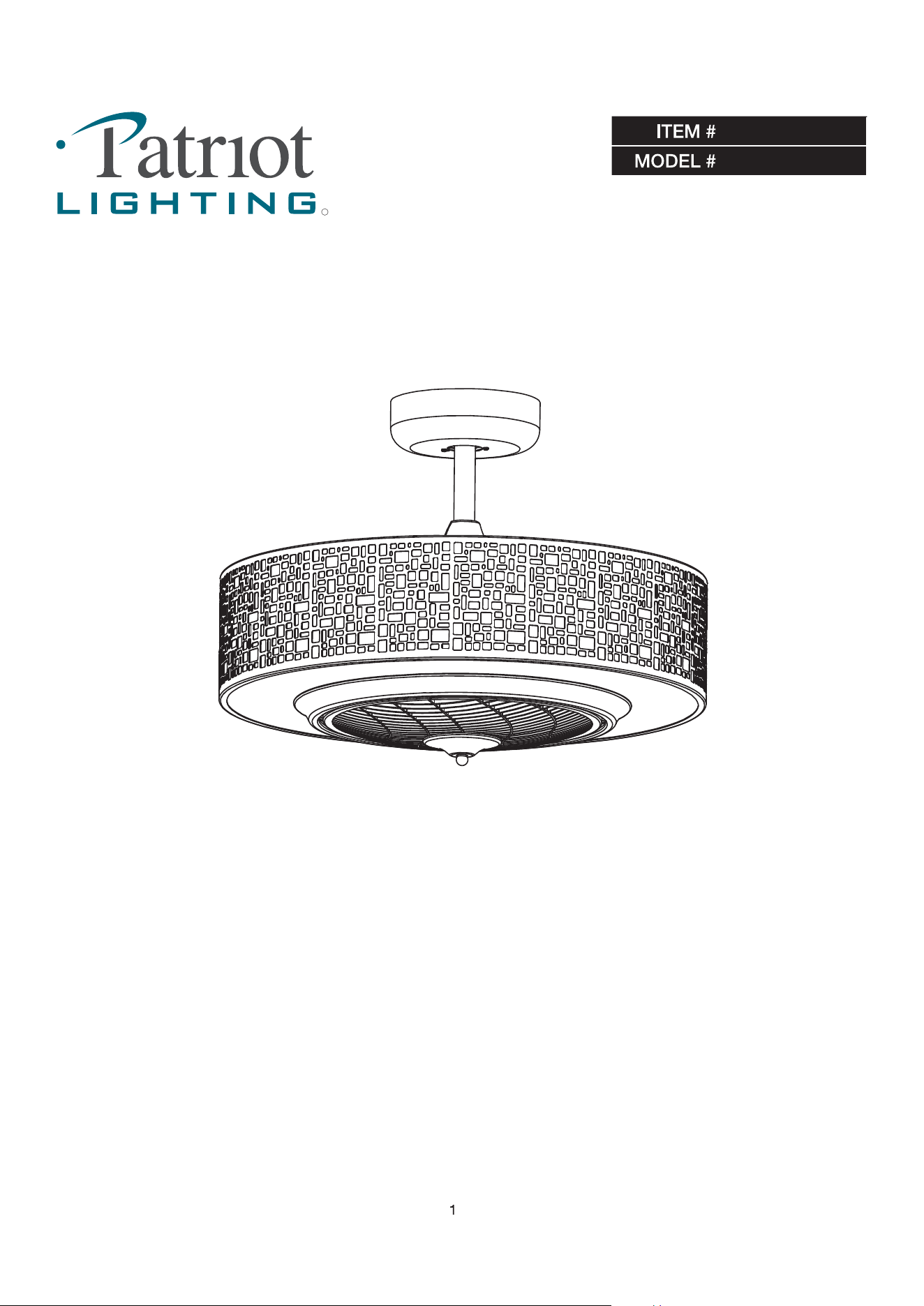
6-LIGHT LED CEILING FAN
HIGHTOWNE
TM
,
,
- Prior to installation of this ceiling fan or removal of a previous ceiling fan, disconnect the power by
turning off the circuit breaker or by removing the fuse at the fuse box.
Use bulbs specified by the marking and/or labels on the ceiling fan. Consult a qualified electrician to ensure correct
branch circuit conductor.
- Consult a qualified electrician for installation of this fan.
- Read all instructions before installing.
Please read and understand this entire manual before attempting to assemble operate or install the product.
WARNING
CAUTION
RISK OF ELECTRIC SHOCK
RISK OF FIRE
This product must be installed in accordance with the applicable installation code by a person familiar with the construction and
operation of the product and hazards involved.
- Turn off the fan before replacing the bulb(s).
SAFETY INFORMATION
To reduce the risk of injury, install the fan so that the blades are at least 2.10 Meters (7 Feet) above the floor and at least 0.5 Meter
(18 inches) from the tip of the blades to the wall.
All set screws must be checked and retightened where necessary before installation.
To reduce the risk of personal injury, do not bend the blade brackets when installing, balancing the blades, or cleaning the fan.
Do not insert foreign objects in between rotating fan blades.
Before changing the fan direction, turn off the fan and wait for the fan blades to stop completely.
If a stationary appliance is not provided with a supply cord and a plug, or with other means for disconnection from the mains supply having
a contact separation of at least 3 mm in all poles, a means for disconnection must be incorporated in the fixed wiring in accordance with
the wiring rules.
NOTE:
The safeguards provided by these safety instructions and by the separate installation instructions are not meant to cover all possible
conditions and situations that may occur. It must be understood that common sense, caution and care are factors which cannot be built into
this product.
These factors must be supplied by the person(s) installing, caring for, and operating the fan.
LIMITED LIFETIME WARRANTY
The limited lifetime warranty covers this ceiling fan, for residential use by the original purchaser, against defects in
material or workmanship as follows:
If your Patriot Lighting ceiling Fan motor fails at any time during the lifetime of the original purchaser due defects in
material or workmanship, we will provide a replacement part free of charge.
If your Fan motor fails at any time within one year after the original date of sale to the original purchaser due to defects
in material or workmanship, we will provide labor to repair the defect, with the exception of take down/reinstallation,
free of charge. The original purchaser will be responsible for all labor costs after this one year period.
If no replacement parts are provided for any part of your Fan motor that fails at any time during your lifetime due to
defects in material or workmanship, we will refund the original purchase price of your Fan.
If your Fan blades, remote controller / pull chain switch, reverse switch, or any accessory, except glass globes and light
bulbs, fails at any time within one year after the original date of purchase due to a defect in material and workmanship,
we will repair or, if we choose, replace the defective blades, switch, or accessory free of charge, with the exception of
take down/reinstallation services.
If the original purchaser ceases to own the Fan, this warranty and any implied warranty, including but not limited to any
implied warranty of merchantability or fitness for a particular purpose, become void. This warranty and any implied
warranty, including but not limited to any implied warranty of merchantability or fitness for a particular purpose, do not
cover glass globes, light bulbs, or finish on any metal portions of the Fan.
This warranty is in lieu of express warranties. The duration of any implied warranty of merchantability or fitness for a
particular purpose, with respect to any Patriot Lighting Ceiling Fan motor , blades, switch, or accessories, is expressly
limited to the period of the express warranty set forth above for such motor, blades, switch, or accessories.
This warranty excludes defects, malfunctions, or failures of any Patriot Lighting Fan that are caused by repairs by
persons not authorized by us, use of parts or accessories not authorized by us, mishandling, improper installation,
modifications or damage to the Fan while in your possession, or unreasonable use, including failure to provide
necessary maintenance.
To obtain service, contact Patriot Lighting Service Department at 1-833-695-2045, 8:30 a.m. - 5 p.m., EST, Monday - .
center. A copy of sales receipt is required in order to obtain service. We will return your Fan freight prepaid. Your Fan
should be properly packed to avoid damage in transit, for we will not be responsible for any such damages.
In no event shall Patriot Lighting Fan be liable for consequential or incidental damages.
Some states do not allow the exclusion or limitation of consequential or incidental damages, in which case the above
limitation or exclusion may not apply.
This warranty gives you specific legal rights and you may also have other rights which vary from state to state.
3
Friday. You will be responsible for all insurance and freight or other transportation charges to our factory or service
Patriot Lighting fixtures, components, and electronic products, when properly installed and under normal conditions of use, are warranted
to be free from defects in materials and workmanship for one year from date of sale.
This Limited Lifetime Warranty includes motor and motor-related parts only, which will be replaced or repaired as determined by Patriot
Lighting during the period in which this warranty is in effect, as further defined below.
Lighting Fixture Warranty
Ceiling Fan Warranty
4
Because of the fan’s natural movement, some connections may become loose. Check the support connections, brackets, and blade
attachments twice a year. Make sure they are secure. It is not necessary to remove the fan from the ceiling.
Clean your fan periodically to help maintain its new appearance over the years. Do not use water when cleaning, as this could damag
sealed with a lacquer to minimize discoloration or tarnishing.
You do not need to oil your fan. The motor has permanently-lubricated sealed ball bearings.
WARNING: Make sure the power is off before cleaning
your fan.
Problem Solution
The fan will not start
Check the main and branch circuit fuses or breakers.
Check the line wire connections to the fan and switch wire connections in the switch housing.
Check the battery in the remote control.
Ensure you are in the normal range of 10-20 feet.
Turn the power off and ensure that the dip switch settings are the same on the remote control and receiver.
The fan is noisy
Ensure all motor housing screws are snug.
Ensure the screws that attach the fan blade bracket to the motor hub are tight.
Ensure the wire nut connections are not rattling against each other or the interior wall of the switch housing.
Allow a 24-hour “breaking in” period. Most noises associated with a new fan disappear during this time.
If you are using the Ceiling Fan light kit, ensure the screws securing the glassware are tight. Check that the light
bulbs are also secure.
Ensure the canopy is a short distance from the ceiling. It should not touch the ceiling.
Ensure your outlet box is secure and rubber isolator pads were used between the mounting plate and outlet box.
The fan wobbles
Check that all blade and blade arm screws are secure.
Most fan wobble problems are caused when blade levels are unequal. Check this level by selecting a point on
the ceiling above the tip of one of the blades. Measure from a point on the center of the blade to the point on the
ceiling. Rotate the fan until the next blade is positioned for measurement, and measure from the same point on
each blade to the ceiling. Repeat for each blade. Any measurement deviation should be within 1/8 in. Run the fan
for ten minutes. If the fan continues to wobble please contact Patriot Lighting Customer Service and a balancing
kit will be sent to you at no charge.
CARE AND MAINTENANCE
TROUBLESHOOTING
plating is
Always unplug the fan before cleaning, disassembly or servicing.
5
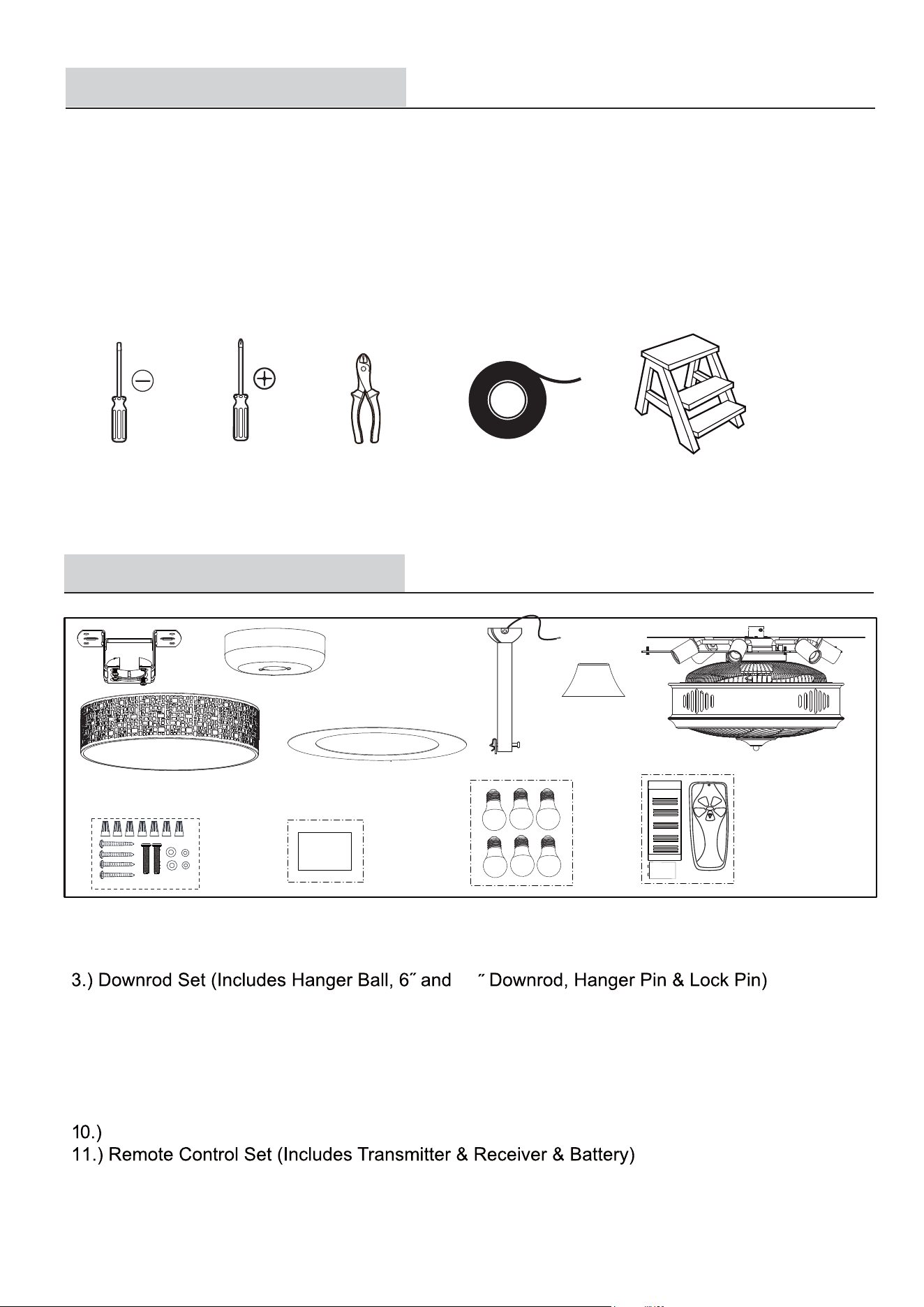
Estimated Assembly Time: 45-60 minutes
PREPARATION
TOOLS REQUIRED
To avoid damaging the product, assemble it on a soft, non-abrasive surface, such as carpet or cardboard. Inspect each part for defects
such as the wire insulation for any cuts, abrasions, or exposed copper that may have occurred during shipping. If there is a defect in the
wire, do not continue the assembly process.
PRE-INSTALLATION
Flathead
screwdriver
Phillips
screwdriver
Electrical tape
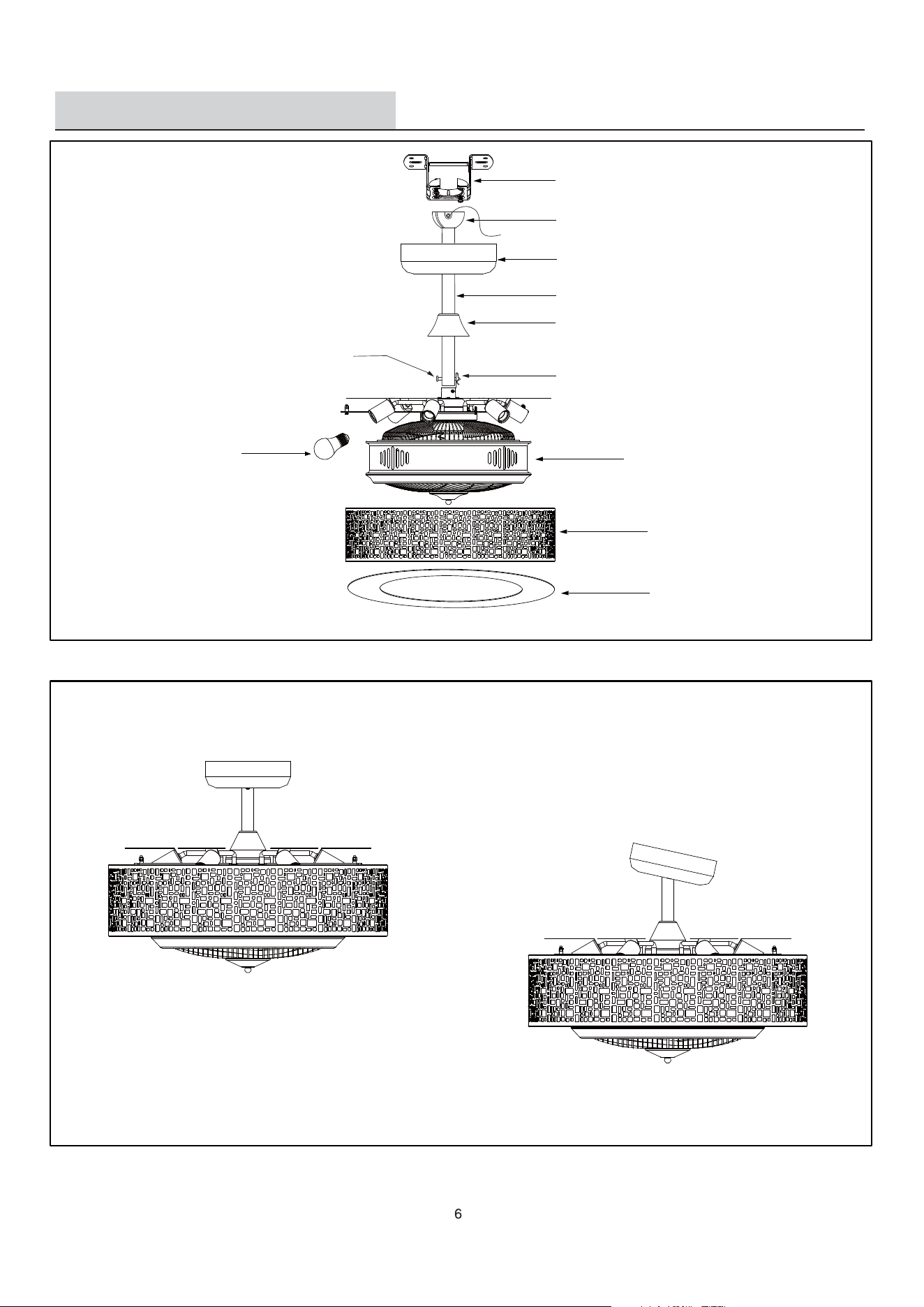
PACKAGE CONTENTS
Unpack your fan and check the contents. You should have the following items.
1.) Hanger Bracket
2.) Canopy
4.) Coupling Cover
5.) Fan Motor assembly
6.) Housing
7.) Diffuser plate
8.) Hardware Kit
9.) Installation Instructions
1
2
3
4
5
7
8
6
9
11
10
Installation
Instruction
9V
Step Ladder
Wire cutter
24
Type A19 E26 Max. 9W LED bulbs (6 PCS)
EXPLODED VIEW DETAIL
Downrod Mount
Slope Ceiling Mount (Up to 23 degrees)
Dual Mount Drawing
Hanger Bracket
Canopy
Downrod
Coupling Cover
Hanger Ball
Coupler
Lock Pin
Hanger Pin
Fan Motor Assembly
Housing
Diffuser Plate
Bulb
INSTALLATION INSTRUCTIONS
Installation Steps :
NOTE: The fan weight is 18.92 lbs (8.6 kg). Be sure the outlet box you are using is securely attached to the building
structure and can support the full weight of the fan. Failure to do so can result in serious injury.
Fig.1
Turn OFF the electric power at the
main fuse or circuit breaker box.
WARNING - Make sure power is
off before attempting installation.
Install hanger bracket onto the outlet box in ceiling using two machine screws,
two washers and two lock washers. To reduce the risk of fire, electric shock,
or personal injury, mount to an outlet box marked "Acceptable for fan support
of 15.9 kg (35 lbs) or less", and use mounting screws provided in assembly kit.
Hanger Pin
Lock Pin
Remove the Lock Pin and take off
the Hanger Pin.
Fig.3
Loosen the set screws in the coupler
until the inside of the channel is clear
of the screw tip.
Insert the downrod into coupler.
Silde Hanger Pin through hole of the
coupler and downrod.
Fig.4
Slide the canopy onto the downrod,
followed by the coupling cover.
Feed the electrical wires from the
fan motor assembly housing through
the downrod.
Fig.5
Hanger Pin
Motor Wires
Motor Wires
Coupler
Downrod
Canopy
Coupling
Cover
Fig.2
Hanger Bracket
Ceiling Joist
Wood Member
(2" x 4" Approx.)
Outlet Box
7
Ceiling
Screws
Slide Lock Pin into Hanger Pin until
it locks into position.
Lock Pin
Note: For slope ceiling installation, make sure that the hanger bracket
opening is facing up-side.
70 AND LOCAL CODES.
THIS INSTALLATION IS TO BE IN ACCORDANCE WITH THE NATIONAL ELECTRICAL CODE, ANSI/NFPA
SAVE
ALL
INSTRUCTIONS.
A
QUALIFIED ELECTRICIAN.
BEFORE
YOU BEGIN INSTALLING
THE
FAN, CAREFULLY
READ
ALL
INFORMATION ON PAGE 2 “SAFETY
IMPORTANT:
INFORMATION” AS WELL AS THE FOLLOWING "INSTALLATION INSTRUCTIONS". IF IN DOUBT, CONSULT
INSTALLATION INSTRUCTIONS
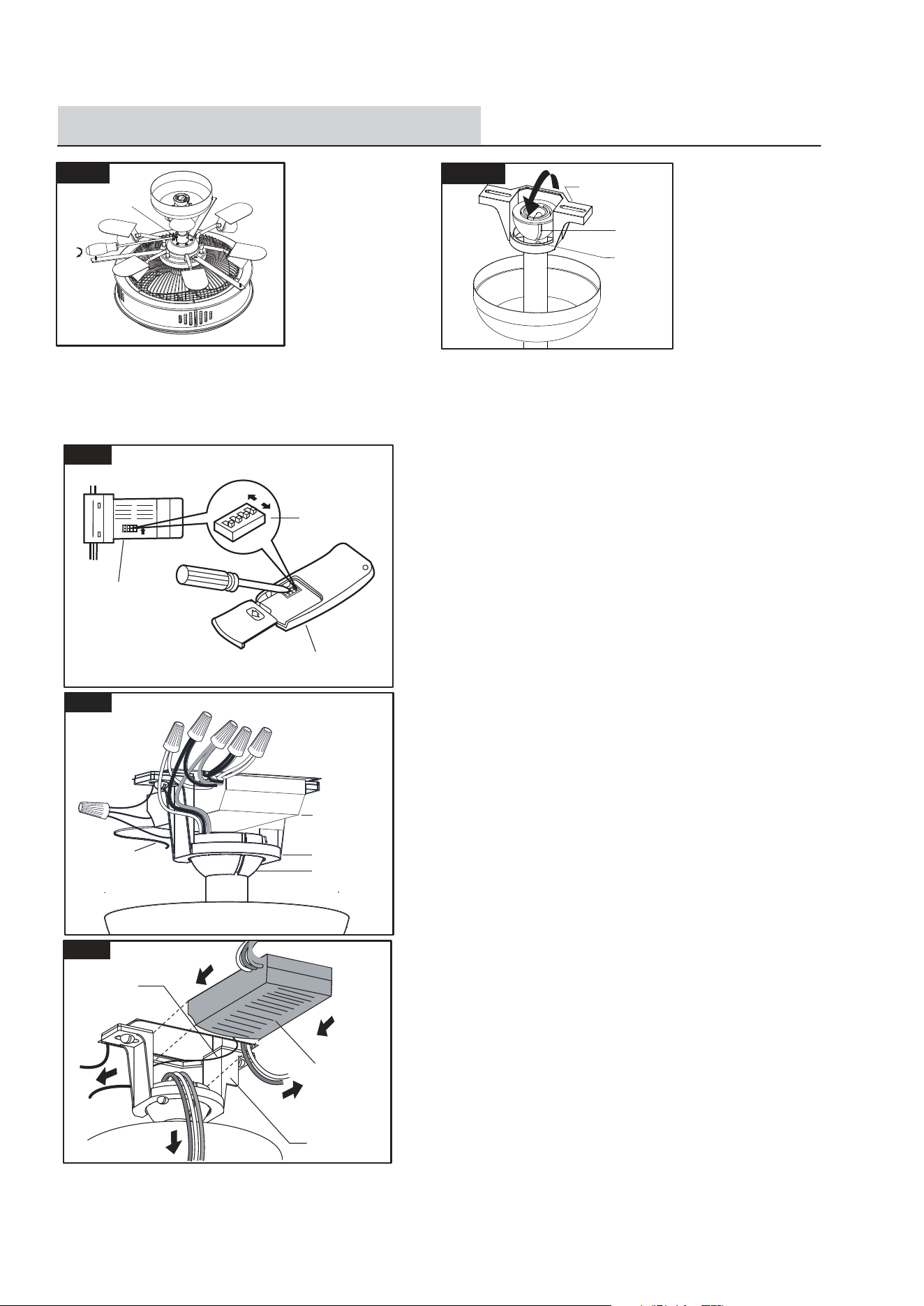
8
Tighten both set screws.
Fig.7
Fig.6
Set Screws
Hang fan on hanger bracket, and turn the fan left and right slightly to
make sure it is seated on the bracket with the keyway pin in the keyway.
Fig.9
Hanger Bracket
Hanger Ball
Receiver
1.
4.
5.
6.
2.
3.
Antenna:
DO NOT CUT
OR SPLICE
Make wire connections:
1) The Motor white wire to the white "MOTOR N " wire from
Receiver with a wire connector.
2) The Motor black wire to the black "MOTOR L" wire from
Receiver with a wire connector.
3) The Motor blue wire to the blue "LIGHT" wire from
Receiver with a wire connector.
4) The white wire from Outlet Box to the white "AC in N" wire
from Receiver with a wire connector.
5) The black (hot) wire from Outlet Box to the black "AC in L"
wire from Receiver with a wire connector.
6) The ground wire from the Outlet Box to the green ground wire
from the Hanger Ball and the green ground wire from the
Hanger Bracket with a wire connector.
Make sure all of wire connectors are connected firmly.
*** Tuck all wire connectors and wires carefully up into the
Outlet Box, EXCEPT the antenna, which should remain outside
Outlet Box.
Trim the excess length of Motor Wires, leaving about six to
eight inches of each wire extending from the motor and then
make the following connection.
Keyway
Keyway
Pin
Hanger Bracket
Fig.10
Antenna
Receiver
Hanger Bracket
Insert the receiver into the hanger bracket with flat side of the
receiver facing the ceiling.
The connections after being made should be turned upward and
pushed carefully up into the outlet box.
Locate the Hand-held Remote Control Transmitter and the
Receiver Unit. There are dip switches inside each of them.
Make sure the switches in both units are aligned exactly
the same way. This system will not function properly unless
both sets of switches are set the same.
ON
Fig.8
Dip Switches
Transmitter
Receiver
Note: For slope ceiling installation, make sure that hanger bracket
opening is facing toward the ceiling.
Spread the wires apart so that the ground wires are on one side
of the outlet box and the other wires are on the other side.
INSTALLATION INSTRUCTIONS
9
Fig.12
Place bulbs included with fan into
the sockets of the light kit.
Fig.11
Canopy Screw
Hanger Bracket
Canopy
Fig.13
Turn ON the electric power at the main
fuse or circuit breaker box.
Fig.15
Fig.14
To access the inner light bulbs, remove
the diffuser plate and carefully pull down-
wards.
Fig.16
Fig.17
Loosen the screws on the brackets.
Bend the diffuser plate slightly and
insert it into the bottom of the housing,
adjust the position if needed..
Replace the light bulbs
Socket
Bulb
Screws
Bracket
Housing
Housing
Diffuser plate
Replace the defective bulbs with a similar
Max. 9W LED bulbs. Re-insert the diffuser
plate into the motor assembly.
Housing
Diffuser plate
Housing
Diffuser plate
screws
provided on the bracket.
to the
Hanger bracket with the two
into the outlet box. Secure the canopy
Make
sure you place the wires safely
Slide the canopy up to the ceiling.
2 bracket screws.
single screw and tighten. Tighten other
line up the holes on the brackets; Insert
Place the housing onto motor assembly,
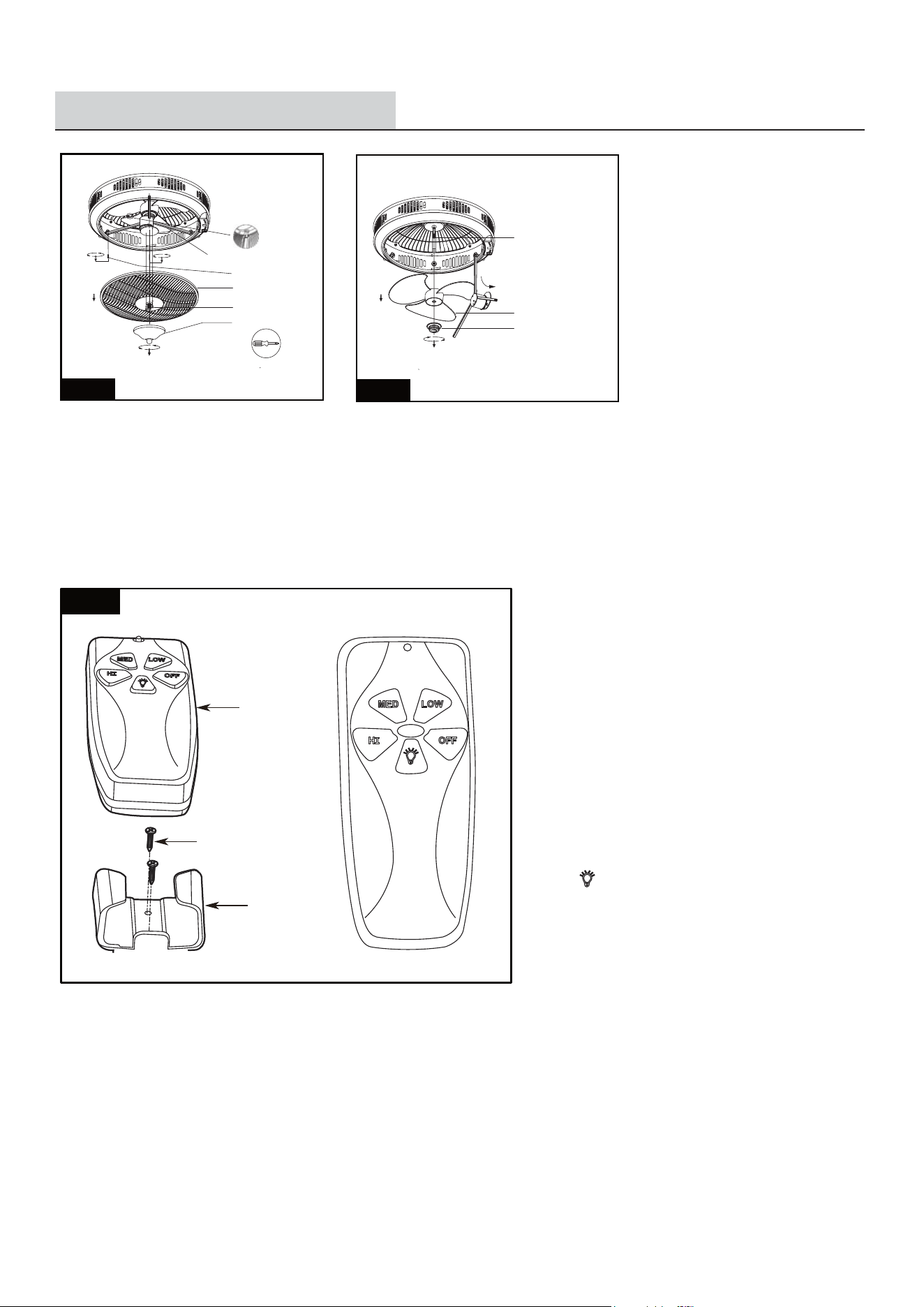
Fig. 20
Attach the bracket with the two screws provided.
Speed Control
Light Control
Press HI, MED, or LOW button to start the fan.
Press OFF to stop the fan.
Press to turns the light on or off.
Remove the panel on the back of the hand control
(transmitter) and install a 9 volt battery. Replace
the panel.
The remote control transmitter comes with a bracket
that can be mounted in any convenient place you
choose. Next to a light switch in the same room as
the ceiling fan is a good place.
Mounting
Bracket
Mounting
Screw
Transmitter
10
INSTALLATION INSTRUCTIONS
Fig.18
Fig.19
6 Body
5 Trigeminal frame
Screwdriver
1 Cover
2 Screw
3 Inducer
4 Screw
1 Plastic Locker
2 Fan Blade
3 Motor
Negative ions Generator cleaning instructions:
Turn off power before removing out protective net as shown above.
Clean with wet cloth first then rub gently with dry cloth.
Caution: make sure that water cannot run into center hole of fan blades. Keep blades dry before installation.