

BG612
MODEL:
Product Type:
6" 1/2 HORSE POWER BENCH GRINDER
Page 1
6" 1/2 HORSE POWER BENCH GRINDER
Study, understand and follow all instructions provided with this
product. Read these instructions carefully before installing, operating,
servicing or repairing this tool. Keep these instructions in a safe
accessible place.
PRODUCT INFORMATION:
DO NOT DISCARD – GIVE TO USER
WARNING
WARNING
MADE IN CHINA
INTENDED USE OF THE TOOL
Caution: To help prevent personal injury
1 YEAR LIMITED WARRANTY
UNPACKING
IMPORTANT
SPECIFICATIONS:
• 1/2 HP single phase electric motor with class E insulation
• Voltage/frequency: 115V-60Hz
• Amps AC: 3.5A
• Maximum no-load speed: 3,550rpm
• Electric power supply cord with 3 prong ground plug; 18-3 SJT x 6’
long (UL listed)
• Grinding wheel dimensions: 6” O.D. x ¾” W. x ½” A.H.
• Quiet and vibration free high torque induction motor
• Heavy duty construction for durability for most grinding applications
• Heavy duty grinding wheel covers
• Two 6” grinding wheels included (#9580GW36 – 36 Grit and
#9580GW60 – 60 Grit)
• Front mount easy access on/off switch for safety and convenience
• Adjustable tool rests and upper tongue guards are included for safe
operation
• Adjustable eye protection shields included for maximum eye and
face protection
• Normal use of this product is likely to expose the user to dust and/or
microscopic particles containing chemicals known to the State of
California to cause cancer, birth defects or other reproductive harm.
Always wear appropriate safety equipment and clothing when using
this product. Study, understand and follow all instructions provided
with this product. Failure to read and follow all warnings and
operating instructions may result in damages and serious injury or
death.
• Always wear ANSI approved goggles when using this product.
(Users and Bystanders).
• Never use this tool for any application other than for which it was
designed.
• Only use accessories designed for this tool.
• Never alter or modify this tool in any way.
• Improper operation and/or maintenance of the tool, modification of
the tool, or use of the tool with accessories not designed for it could
result in serious injury or death.
• Always select the correct accessories of the correct size and design
for the job that you are attempting to perform.
• Always work in a clean, safe, well-lit, organized and adequately
equipped area.
• Do not begin repairs without assurance that vehicle is in secure
position, and will not move during repair.
When unpacking, check the parts diagram and part number listing on
page 4 to make sure all parts are included. If any parts are missing or
damaged, please call your dstributor.
Read these instructions carefully before installing, operating, servicing
or repairing this tool. Keep these instructions in a safe accessible place.
The manufacturer warrants this product to the original user against
defective material or workmanship for a period of 1 year from the
date of purchase.
The manufacturer reserves the right to determine whether the part or
parts failed because of defective material, workmanship or other
causes. Failures caused by accident, alteration, or misuse are not
covered by this warranty.
The manufacturer, at its discretion, will repair or replace products
covered under this warranty free of charge. Repairs or replacements
of products covered under this warranty are warranted for the
remainder of the original warranty period.
The manufacturer or its authorized service representatives must
perform all warranty repairs. Any repair to the product by unauthor-
ized service representatives voids this warranty. The rights under this
warranty are limited to the original user and may not be transferred to
subsequent owners.
This warranty is in lieu of all other warranties, expressed or implied,
including warranties of merchantability and fitness for a particular
purpose. Some states do not allow the exclusion or limitations of
incidental or consequential damages, so the above limitations may
not apply to you.
This bench grinder is designed to sharpen drill bits, blades, chisels,
flat screwdrivers, etc. Do not use this tool outside of the designed
intent. Never modify the tool for any other purpose or use.
Page 2
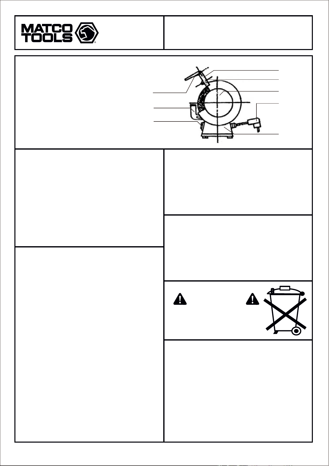
• MOTOR is ½ HP single phase with class E insulation constructed of
aluminum, steel and cast iron
• WHEEL COVER is constructed of steel to protect from injury, help
suppress sparks and flying debris, and to fasten eye protection
shields and safety guards
• GRINDING WHEELS (6” x ¾” x ½” 36 grit and 60 grit)
• ON/OFF SWITCH
• POWER SUPPLY CORD WITH 3 PRONG GROUND PLUG
• CAPACITOR
1. Fasten the (B) Tool Rests to the lower inside surface of the (E)
Wheel Covers with the screws and washers provided. Adjust the (B)
Tool Rests to 1/8” (3mm) from the Grinding Wheel surface and
tighten screws securely. DO NOT EXCEED 1/8” (3mm).
2. Fasten the (G) Upper Tongue Guards to the upper inside surface of
the (E) Wheel Covers with the screws and washers provided. Adjust
the (G) Upper tongue Guards to ¼” (6mm) from the Grinding Wheel
surface and tighten screws securely. DO NOT EXCEED ¼” (6mm).
3. Fasten the (D) Eye Protection Shield Brackets and (A) Eye
Protection Shields with the screws and washers provided. Adjust
the (D) Eye Protection Shield Brackets to the appropriate distance
for the work being performed and tighten screws securely.
4. Mount the Bench Grinder using the two holes in the (H) Motor Base
to a firm surface securely, such a work bench or a qualified
pedestal or stand. Mounting screws are not included.
• Always disconnect power supply cord before servicing or replacing
grinding wheels.
• Replace cracked or damaged grinding wheels immediately.
• Always use safety guards and eye protection shields.
• Ensure tool rests and eye protection shields are properly adjusted.
• Do not over tighten wheel nut.
• Maintain a maximum distance of 1/8” (3mm) between grinding wheel
and tool rests as the grinding wheel wears and diameter decreases.
• Use only grinding wheels with a RPM rating equal to or greater than
RPM of the grinder motor.
• Ensure grinding wheels rotate freely before turning power on.
• Do not stand in front of grinder when turning power on. Always stand
to the side until grinder comes up to full speed to make sure it is
operating safely.
• Always inspect and ring test a new grinding wheel before mounting
and allow the new wheel to rotate freely for at least one minute
before using grinder. The grinding wheel can be ring tested by
tapping the wheel gently with a nonmetallic object such as a
screwdriver handle or plastic hammer. The wheel is in good
condition If you hear a ring. The wheel is cracked or defective if the
sound is more of a thud or dead sound.
• Do not operate the grinder with the wheel guards off.
• Do not grind on the side of the grinding wheel or use the wheel for
cutting purposes.
• Do not overload the grinder.
• Use a wheel dresser to remove imperfections and keep the grinding
wheel in good safe condition.
• Maintain a maximum distance of ¼” (6mm) between the grinding
wheel and upper tongue guard as the grinding wheel wears and
diameter decreases.
1. Inspect power supply cord and plug into a properly grounded
electrical outlet. If an extension cord is necessary, always use a 3
wire grounded extension cord that is UL listed and is the proper
size for the length of the extension cord.
2. Check all safety guards for proper adjustment and are tightened
securely to assure safe operation.
3. Rotate the grinding wheels freely to assure there are no obstructions.
4. Stand to the side and turn switch on and allow grinder to reach full
speed before operating.
1. Disconnect power supply cord.
2. Remove outside wheel covers.
3. Remove nuts and flanges holding grinding wheels on by turning
the nuts counterclockwise on the right side and clockwise on the
left side and remove old grinding wheels. Note: The nut on the left
side has left hand threads and the nut on the right side has right
hand threads.
4. Inspect and test new grinding wheels before installing using the
ring test as shown in the precautions. Do not use grinding wheels if
they do not pass test.
5. Install new grinding wheels and tighten nuts securely.
6. Install outside wheel covers.
7. Connect power supply cord, stand to the side and turn switch on.
Allow grinder to run for one minute and reach full speed while
assuring that the wheel is running true before operating
GRINDING WHEEL REMOVAL AND
INSTALLATION INSTRUCTIONS
OPERATING INSTRUCTIONS
ASSEMBLY INSTRUCTIONS
PARTS INDENTIFICATION
PRECAUTIONS ON USING BENCH GRINDERS
(A) Eye Protection Shield
(B) Tool Rest
(C) On/Off Switch
(D) Eye Protection Shield Bracket
(E) Wheel Cover
(F) Electric cord with plug
(G) Upper Tongue Guard
(H) Motor Base
A
D
G
E
F
H
B
C
Do not dispose of electrical products with
household waste. Please check with your
local authorities for proper disposal and
recycling facilities in your area.
MAIN STRUCTURE
WARNING
BG612
MODEL:
PRODUCT TYPE:
6" 1/2 HORSE POWER BENCH GRINDER

Page 3
IMPORTANT SAFETY INSTRUCTION
1. KEEP WORK AREA CLEAN. Cluttered work area and benches invite injuries.
2. CONSIDER WORK AREA ENVIRONMENT. Keep work area well lit. Do not expose power tools to
rain or water. Do not use power tools in or near damp or wet locations. Do not use tool near flam-
mable liquids, gases or other flammable products.
3. KEEP CHILDREN AWAY. Do not allow children or visitors in work area.
4. STORE IDLE TOOLS. Store tools in a dry location without access to others when not in use.
5. DO NOT FORCE TOOL. Using the tool for which it was intended will result in a more safe and
efficient job and a longer tool life.
6. USE RIGHT TOOL. Do not use a small tool or accessory for a large job which it was not intended
for.
7. DRESS PROPERLY. Do not wear loose clothing or jewelry. Contain long hair from being exposed.
Loose items can get caught in wheel and cause serious injury or death. Wear approved protective
gloves and slip resistant footwear.
8. EXTENSION CORD USE. If the use of an extension cord is necessary, always use a 3 wire
grounded extension cord that is UL listed and is the proper size for the length of the extension cord.
An undersized or damaged extension cord can cause overheating, loss of power, fire, damages and
serious injury or death.
9. ALWAYS WEAR ANSI APPROVED SAFETY GLASSES. Use face and dust mask for face and
breathing protection.
10. DO NOT OVERREACH WHILE GRINDING. Always keep proper footing and balance while grinding.
11. MAINTAIN TOOLS WITH CARE. Keep hands and tools clean and inspect regularly for safe and
efficient performance. Follow instructions for inspecting grinding wheels, power supply cord and
safety guard adjustments.
12. REMOVE FOREIGN OBJECTS. Always assure that wrenches and all tools used for repairs or
adjustments are removed and clear of the grinder before turning on.
13. AVOID UNINTENTIONAL STARTING. Do not hold objects in hand while turning switch on to
prevent unintentional starting of the grinder.
14. STAY ALERT WITH WHAT YOU ARE DOING. Use common sense and do not operate tool when
you are tired.
15. CHECK FOR DAMAGED PARTS. Before each use, the grinder should be checked for any dam-
aged or loose parts, alignment and binding of moving parts, proper switch operation and proper
adjustment of all safety guards. Do not use grinder until all damaged or defective parts are repaired
or replaced properly by an authorized service representative for safe operation.
16. ACCESSORIES. Use only accessories equal to or greater than original equipment accessories. Use
only grinding wheels that are rated 3,550rpm or higher.
17. REPLACEMENT PARTS. Use only identical original equipment replacement parts when repairing or
servicing.
18. SAVE THESE INSTRUCTIONS FOR FUTURE REFERENCE.
When using electric tools, always read and follow all safety precautions, warnings and
operating instructions to reduce the risk of fire, electric shock, property damage and personal
injury. Failure to read and follow all warnings and operating instructions may result in
damages and serious injury or death.
BG612
MODEL:
PRODUCT TYPE:
6" 1/2 HORSE POWER BENCH GRINDER

Página 1
Estudie, entienda y siga todas las instrucciones que se proveen con
este producto. Lea las instrucciones detenidamente antes de instalar,
operar, dar servicio o reparar esta herramienta. Guarde estas
instrucciones en un lugar seguro y accesible.
INFORMACIÓN DEL PRODUCTO:
NO LO DESCARTE O DESECHE, ENTREGESELO AL USUARIO
ADVERTENCIA
ADVERTENCIA
HECHO A CHINA
USO APLICACIÓN DE LA HERRAMIENTA
IMPORTANTE
GARANTÍA LIMITADA DE UN AÑO
ESPECIFICACIONES:
• Motor monofásico eléctrico de 1/2 caballo de potencia con
aislamiento clase E
• Tensión / frecuencia: 115V-60Hz
• A CA: 3,5 A
• La velocidad máxima en vacío: 3,550 rpm
• Cable de suministro de energía eléctrica con conexión de 3 clavijas;
18-3 SJT x 6'long (Registrado UL)
• Dimensiones de la muela: 6 "O.D. x 3/4"An. x 1/2"A.H.
• Motor de alta inducción, silencioso y libre de vibraciones
• Construcción de alta resistencia para mas durabilidad en la mayoría
de las aplicaciones de molienda
• Cubierta de las ruedas amoladoras de alta calidad
• Dos muelas de 6” incluido (# BG612-GW36 – de 36 Granos y #
BG612-GW60 – de 60 Granos)
• Botón de encendido / apagado de montaje frontal para fácil acceso,
mayor seguridad y comodidad
• Se incluyen los descansos o apoyos (ajustables) para las
herramientas y escudos de lengüeta superior para un funciona-
miento seguro
• Protectores oculares ajustables (incluidos) para máxima protección
ocular y facial
• El uso normal de esta herramienta puede exponer al usuario al
polvo o a partículas microscópicas que contienen sustancias
químicas que se conocen en el estado de. California por causar
cáncer, defectos del nacimiento u otros daños reproductivos.
Siempre use equipo y ropa de seguridad adecuados para trabajar
con esta herramienta. Lea, comprenda y siga todas las instruccio-
nes incluidas con esta herramienta. Omitir la lectura y el no seguir
todas las advertencias e instrucciones de operación puede traer
como consecuencia daños y lesiones graves o hasta la muerte.
• Siempre use guantes del tipo aprobado por la ANSI para trabajar
con esta herramienta. (tanto usuarios como espectadores).
• Nunca utilice esta herramienta para cualquier otra cosa que no
sean las aplicaciones para lo que fue diseñada.
• Sólo utilice los accesorios diseñados para esta herramienta.
• No modifique o altere esta herramienta de ninguna manera.
• El funcionamiento y/o mantenimiento inadecuado de la
herramienta, la modificación, o la utilización de la. herramienta con
accesorios inadecuados podrían causar. lesiones graves o la
muerte.
• Siempre usar los correctos accesorios para el trabajo que Ud. está
realizando.
• Trabaje siempre en un área limpia, segura, bien iluminada,
organizada y equipada adecuadamente.
• NUNCA empiece reparaciones sin estar seguro de que el vehículo
esté en posición segura y que no se mueva durante la reparación.
Lea las instrucciones detenidamente antes de instalar, operar, dar
servicio o reparar esta herramienta. Guarde estas instrucciones en
un lugar seguro y accesible.
DESEMPACADO
Cuando desempaque el producto, revise el diagrama y la lista de
piezas en la página 4 para verificar que se hayan enviado todas
las piezas. En caso de que falten piezas o que estén dañadas,
comuníquese con su distribuidor.
• El fabricante garantiza este producto al usuario original contra
defectos de materiales o de mano de obra durante un periodo de
un año a partir de la fecha de compra.
• El fabricante se reserva el derecho a determinar si una pieza o
piezas fallaron debido a material defectuoso, mano de obra, o por
otras causas. Esta garantía no cubre fallas causadas por acciden-
tes, alteraciones o uso indebido.
• El fabricante, a su entera discreción, reparará o reemplazará los
productos cubiertos por esta garantía sin costo alguno. Las
reparaciones o reemplazos de productos cubiertos por esta
garantía quedan garantizados durante el resto del periodo original
de garantía.
• El fabricante o sus representantes autorizados de servicio deben
llevar a cabo todas las reparaciones de garantía. Toda reparación
hecha al producto por representantes de servicio no autorizados
invalida la presente garantía. Los derechos que ampara esta
garantía están limitados al usuario original y no se pueden
transferir a dueños posteriores.
• Esta garantía reemplaza a todas las demás garantías expresas o
implícitas, incluyendo garantías de comercialización e idoneidad
para un propósito particular. Algunos estados no permiten la
exclusión o limitaciones de daños incidentales o imprevistos, de
manera que las limitaciones mencionadas anteriormente pueden
no ser aplicables en su caso.
Esta amoladora de banco está diseñada para afilar brocas, cuchillas,
cinceles, destornilladores planos, etc. No utilice esta herramienta
fuera de la intención de su diseño. Nunca modifique la herramienta
para cualquier otro propósito o uso.
AMOLADORA DE BANCO DE 6" DE 1/2
CABALLO DE POTENCIA
AMOLADORA DE BANCO DE 6" DE 1/2
CABALLO DE POTENCIA
BG612
MODEL: TIPO DE PRODUCTO:
Precaución: Para ayudar a evitar lesiones
a las personas
Página 2
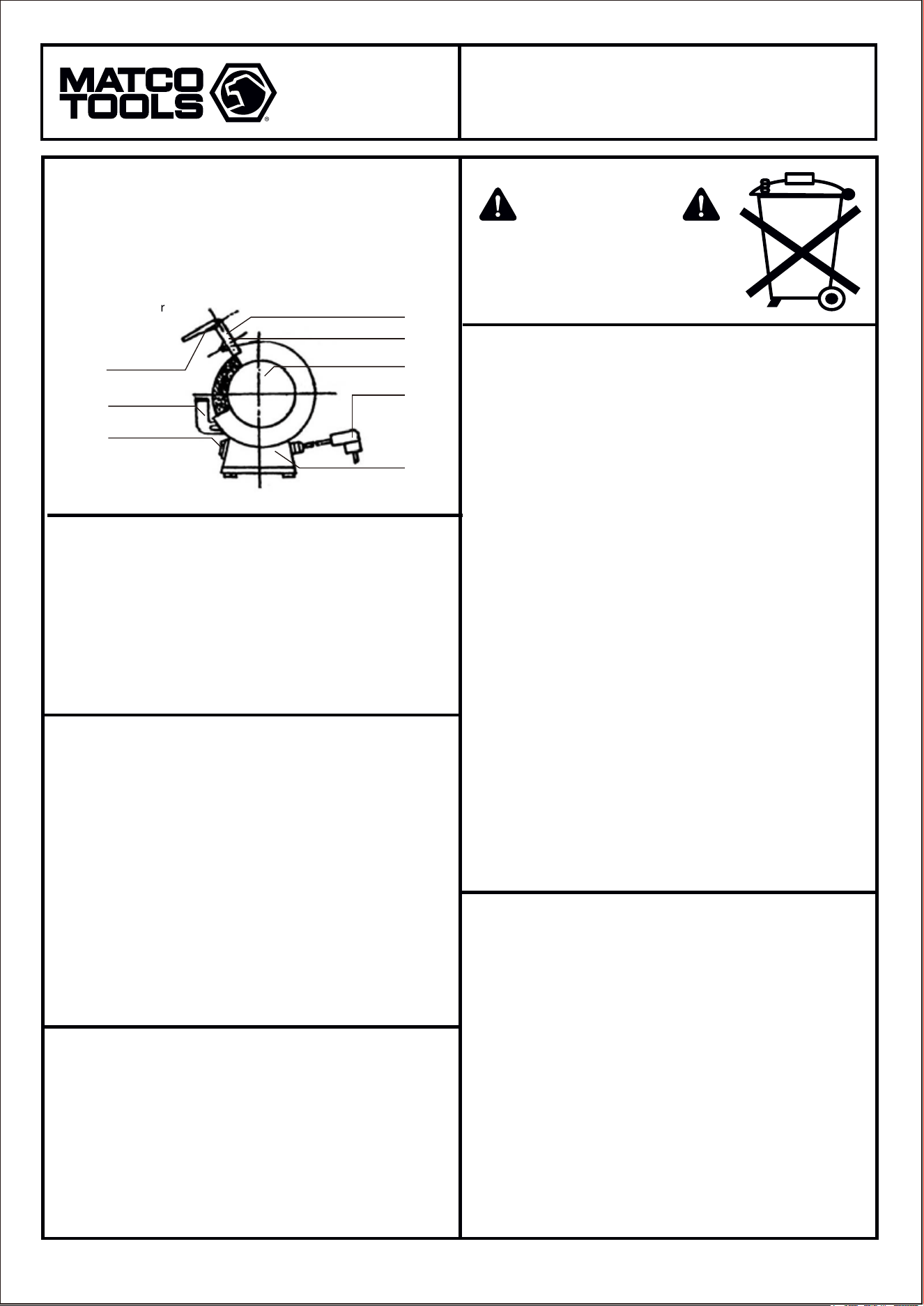
• MOTOR monofásico eléctrico de 1/2 caballo de potencia con
aislamiento clase E, fabricado en aluminio, acero y hierro fundido
• Con cubiertas para las muelas fabricadas en acero para protegerse
contra lesiones, ayudar a suprimir las chispas, escombros que
vuelan, para fijar los protectores oculares y faciales los y los
escudos de seguridad
• MUELAS (6 "x 3/4" x 1/2" de 36 y 60 granos)
• Botón de encendido / apagado
• Cable de suministro de energía eléctrica con conexión de 3 clavijas
• Capacitor
• Desconecte siempre el cable de suministro de energía eléctrica
antes de reparar o reemplazar las muelas.
• Reemplace las muelas rotas o dañadas inmediatamente.
• Utilice siempre dispositivos de seguridad y protección para los ojos.
• Asegúrese de que los descansos o apoyos de herramientas y
protección de los ojos están correctamente ajustadas.
• No apriete demasiado la tuerca de la rueda.
• Mantenga una distancia máxima de 1/8 "(3mm) entre muela y
descansos de herramientas ya que la muela se desgasta y
disminuye el diámetro.
• Use sólo las muelas con capacidad de RPM igual o mayor que la
RPM del motor de la amoladora.
• Asegúrese de que las muelas giran libremente antes de conectar la
amoladora a la electricidad .
• No se pare en frente de la amoladora cuando esta encendiendo la
maquina . Siempre párese a un lado hasta que la amoladora
alcance su velocidad máxima para asegurarse de que está
funcionando de manera segura.
• Siempre inspeccione y pruebe las nuevas muelas antes de
montarlas y permita que la nueva rueda gire libremente por lo
menos un minuto antes de usar la amoladora. La muela puede ser
analizada y probada pulsando la rueda con cuidado con un objeto
no metálico como un mango de destornillador o un martillo de
plástico. La rueda está en buenas condiciones si escucha un timbre.
La rueda está rota o defectuosa si el sonido es más como un golpe
o un sonido muerto.
• No use la amoladora sin los escudos protectores de las muelas.
• No lije o amuele por los lados de la muela ni use la rueda con el
propósito de hacer cortes
• No sobrecargue la amoladora.
• Utilice una herramienta especial para re acondicionar quitar
imperfecciones y mantener la muela en buenas condiciones de
seguridad.
• Mantener una distancia máxima de ¼ "(6 mm) entre la muela y el
escudo de lengüeta superior ya que el desgaste de la muela
disminuye el diámetro.
1. Inspeccione el cable eléctrico y enchufe en una toma de corriente
con conexión de 3 clavijas. Si es necesario un cordón de
extensión, siempre utilice uno con conexión de 3 clavijas que es
listado con UL y que sea del tamaño y longitud adecuado.
2. Revise que todos los protectores de seguridad estén bien
apretados y con el ajuste correcto para operar con seguridad.
3. Asegúrese de que las muelas giran libremente para que no haya
obstrucciones.
4. Párese a un lado y coloque el interruptor de encendido y permita
la amoladora alcance la velocidad máxima antes de operar.
1. Fije el punto (B descansos de herramienta) a la superficie inferior
interna de la cubierta de muela (E) con los tornillos y arandelas
suministrados. Ajuste (B el descanso de herramienta) a 1/8" (3
mm) de la superficie de la muela y apriete los tornillos. No supere
el 1/8 "(3 mm).
2. Fije (G escudos de lengüeta superior) a la superficie interior
superior de la cubierta de la muela (E) con los tornillos y arande-
las suministrados. Ajuste (G escudos de lengüeta superior) a 1/4"
(6 mm) de la superficie de la muela y apriete los tornillos. No
Supere 1/4" (6 mm).
3. Fije (D soporte del Escudo de Protección ocular y el (A escudo de
Protección de los ojos con tornillos y arandelas suministrados.
Ajuste (D soporte del escudo de Protección ocular a la distancia
adecuada para el trabajo que se realiza y apriete los tornillos.
4. Monte la Amoladora de Banco utilizando los dos agujeros en el
punto (H) Base del Motor a una superficie firme y segura, como un
banco de trabajo, o un pedestal o soporte cualificado. Los tornillos
de montaje no están incluidos.
1. Desconecte el cable de alimentación.
2. Retire las cubiertas de las ruedas.
3. Retire las tuercas y bridas, sostenga las ruedas de molienda, girar
las tuercas en sentido contrario al reloj en el lado derecho y en
sentido al reloj en el lado izquierdo y quitar las muelas viejas. Nota:
La tuerca en la parte izquierda tiene rosca izquierda y la tuerca en
la parte derecha tiene rosca a la derecha.
4. Inspeccionar y probar las nuevas muelas antes de instalar
utilizando la prueba del sonido como se muestra en la sección de
PRECAUCIONES. No utilice muelas si no pasan la prueba.
5. Instalar las nuevas muelas apretando y asegurando las tuercas.
6. Instale las cubiertas exteriores.
7. Conecte el cable de suministro de energía, estando a un lado de
la amoladora (no enfrente) encienda el interruptor. Permita girar la
amoladora durante un minuto hasta que alcance la velocidad
máxima para asegurarse que la rueda esta girando correctamente
antes de operar
INSTRUCCIONES PARA INSTALAR O
REMOVER LAS MUELAS
INSTRUCCIONES DE USO
INSTRUCCIONES DE MONTAJE
IDENTIFICACION DE LAS PIEZAS
PRECAUCIONES AL USAR LA AMOLADORA
(A) Escudo Protector de los ojos
(B) Descansos o apoyos de la herramienta
(C) Botón de Encendido / Apagado
(D) Soporte de los Escudos de Protección ocular
(E) Cubiertas de las Muelas
(F) Cordón Eléctrico con Enchufe
(G) Escudos de Lengüeta
(H) Base del Motor
A
D
G
E
F
H
B
C
No se deshaga de productos eléctricos en
la basura doméstica. Por favor, consulte
con las autoridades locales para su
correcta eliminación y reciclaje en su área.
ESPECIFICACIONES
WARNING
AMOLADORA DE BANCO DE 6" DE 1/2
CABALLO DE POTENCIA
BG612
MODEL: TIPO DE PRODUCTO:

Página 3
INSTRUCCIONES IMPORTANTES DE SEGURIDAD
1. MANTENGA LIMPIA el área de trabajo. Áreas de trabajo y mesas desordenadas pueden provocar
lesiones.
2. CONSIDERE E INSPECCIONE el área de trabajo. Mantenga el área de trabajo bien iluminada. No
exponga las herramientas eléctricas a la lluvia o al agua. No utilice las herramientas eléctricas en o
cerca de zonas húmedas o mojadas. No utilice la herramienta cerca de líquidos inflamables, gases u
otros productos inflamables.
3. MANTENGA ALEJADOS A LOS NIÑOS. No permita a niños o visitantes en el área de trabajo.
4. GUARDE LAS HERRAMIENTAS. Guarde las herramientas en un lugar seco y sin acceso a los demás
cuando no estén en uso.
5. NO FUERCE LA HERRAMIENTA. Utilice la herramienta para lo que fue diseñada dará lugar a un
trabajo más seguro, eficiente y una vida útil más larga.
6. UTILICE LA HERRAMIENTA ADECUADA. No utilice una herramienta pequeña o un accesorio para un
trabajo para el que no fue diseñado.
7. VESTIMENTA ADECUADA. No use ropa suelta ni joyas. No mantenga el pelo largo expuesto. Artículos
sueltos pueden quedar atrapados en las ruedas y provocar lesiones graves o la muerte. Use guantes
protectores aprobados y calzado resistente y antiderrapante.
8. USO DE CABLE DE EXTENSION. Si es necesario el uso de un cable de extensión, siempre utilice un
cable de extensión con conexión de 3 hilos que es listado con UL y es del tamaño adecuado para la
longitud del cable de extensión. Un cable de extensión que no es del tamaño o dañado puede causar un
sobrecalentamiento, pérdida de energía, fuego, daños y lesiones graves o la muerte.
9. SIEMPRE póngase gafas de seguridad aprobadas. Utilice una máscara facial para protegerse del
polvo y la respiración.
10. No se estire para alcanzar alguna cosa mientras que la amoladora esta trabajando. Siempre
mantenga el equilibrio apropiado mientras que esta moliendo.
11. CUIDE SUS HERRAMIENTAS. Mantenga las manos y herramientas limpias e inspecciónelas regular-
mente para un desempeño seguro y eficiente. Siga las instrucciones para la inspección de muelas,
cable y los ajustes de seguridad de los escudos protectores.
12. RETIRE objetos extraños. Asegúrese siempre de que las llaves y todas las herramientas utilizadas
para las reparaciones o ajustes sean retirados de la amoladora antes de encenderla.
13. EVITE EL ARRANQUE ACCIDENTAL. No mantenga los objetos en la mano mientras gira el interruptor
para evitar el arranque imprevisto del molino.
14. ALERTA CON LO QUE ESTÁ HACIENDO. Use el sentido común y no trabaje o utilice la herramienta
cuando esté cansado.
15. REVISE LAS PARTES DAÑADAS. Cada vez que use la amoladora debe comprobar si hay piezas
dañadas o sueltas, alineación y dobleces en partes móviles, operación de cambio y el ajuste adecuado
de todas las protecciones de seguridad. No utilice la amoladora hasta que todas las piezas dañadas o
defectuosas sean reparadas o reemplazadas adecuadamente por un técnico de servicio autorizado para
poder operar con seguridad.
16. ACCESORIOS. Utilice sólo los accesorios iguales o superiores a los accesorios del equipo original.
Utilice únicamente las muelas que están clasificadas 3550 rpm o superior.
17. REPUESTOS. Utilice únicamente piezas de recambio originales idénticas al reparar o dar servicio a la
unidad.
18. GUARDE ESTAS INSTRUCCIONES PARA REFERENCIA FUTURA.
Cuando utilice herramientas eléctricas, siempre lea y siga todas las precauciones de seguridad,
advertencias e instrucciones de funcionamiento para reducir el riesgo de incendio, descargas
eléctricas, daños a la propiedad y lesiones personales. El no leer y seguir todas las advertencias e
instrucciones de funcionamiento puede resultar en daños y lesiones graves o la muerte.
AMOLADORA DE BANCO DE 6" DE 1/2
CABALLO DE POTENCIA
BG612
MODEL: TIPO DE PRODUCTO:
Page 4
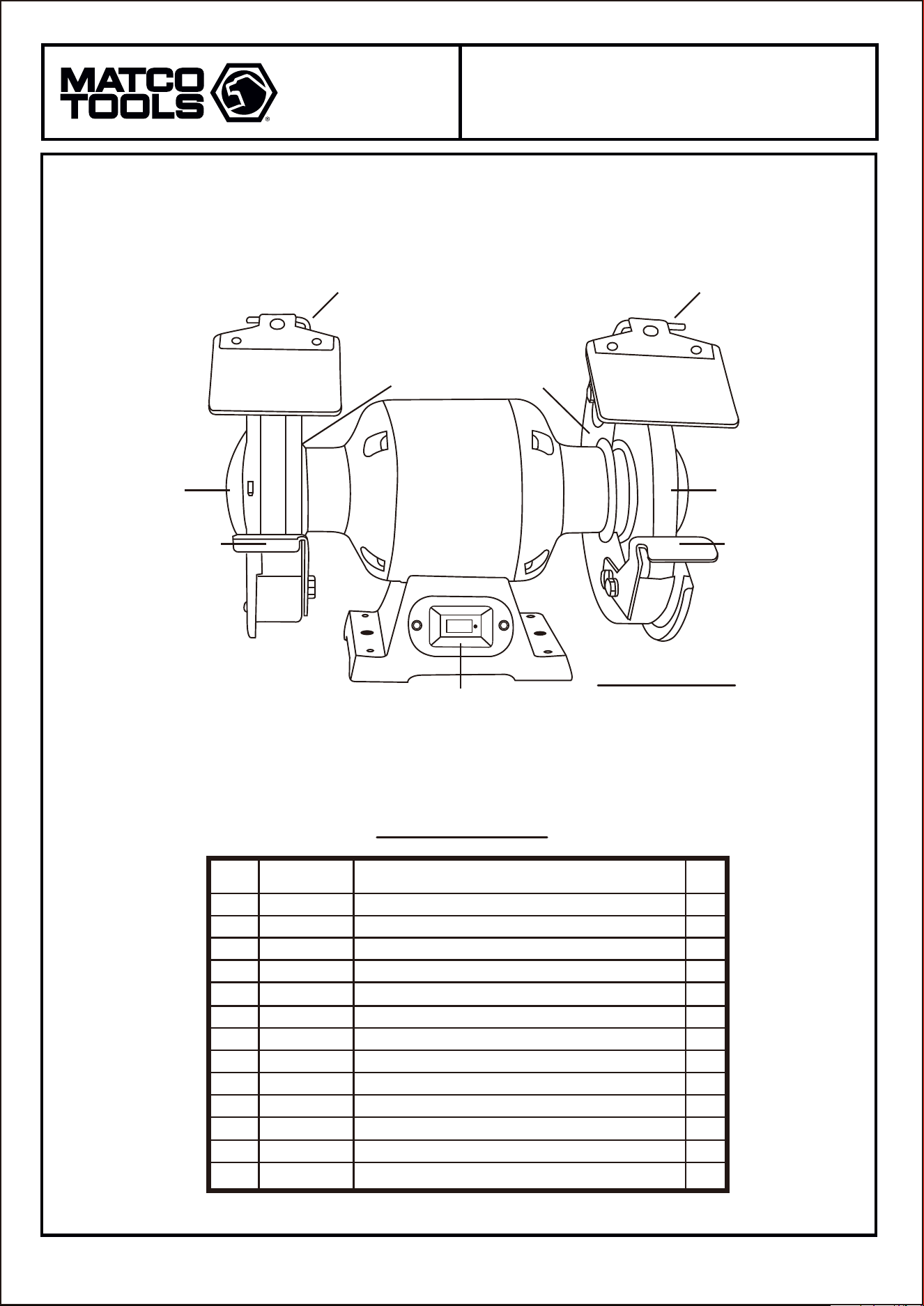
PARTS BREAKDOWN
07162013
Parts List
NOT SHOWN
Index
No.
Part No. Description Q’ty
Eye Protection Shield (sold individually)
Tool Rest Left
Tool Rest Right
On / Off Switch
Eye Protection Shield Bracket (sold individually)
Wheel Cover (sold individually)
Upper Tongue Guard Left
Upper Tongue Guard Right
Guard Left
Guard Right
Eye Protection Shield Rod Left
Eye Protection Shield Rod Right
Hardware Kit
A1
B1
B2
C1
D1
E1
G1
G2
I1
I2
J1
J2
K1
2
1
1
1
2
2
1
1
1
1
1
1
1
BG612-01
BG612-02
BG612-03
BG612-04
BG612-05
BG612-06
BG612-07
BG612
-08
BG612-09
BG612-10
BG612-11
BG612-12
BG612-HK
BG612-11 BG612-12
BG612-09 BG612-10
BG612-06 BG612-06
BG612-02 BG612-03
BG612-05
BG612-07
BG612-08
BG612-HK Hardware Kit
BG612-04
BG612-01 BG612-01
BG612
MODEL:
PRODUCT TYPE:
6" 1/2 HORSE POWER BENCH GRINDER