User Manual
Bedienungsanleitung
de
en
1-channel subwoofer amplier with crossover
1-Kanal Subwoofer-Verstärker mit Frequenzweiche
201 X-OVER
24V EDITION

2
Herzlichen Glückwunsch!
Allgemeine Hinweise
Sehr geehrter Kunde,
wir gratulieren Ihnen zum Kauf dieses
hochwertigen HELIX Verstärkers.
Audiotec Fischer setzt mit dem AMPLIFY
201 X-OVER neue Maßstäbe im Bereich der
Verstärkertechnik. Dabei protieren Sie als
Kunde direkt von unserer mehr als 35-jährigen
Erfahrung in der Forschung und Entwicklung von
Audiokomponenten.
Dieser Verstärker wurde von uns nach neuesten
technischen Erkenntnissen entwickelt und
zeichnet sich durch hervorragende Verarbeitung
und eine überzeugende Anwendung ausgereifter
Technologien aus.
Viel Freude an diesem Produkt wünscht Ihnen
das Team von
AUDIOTEC FISCHER
Allgemeines zum Einbau von HELIX-Kompo-
nenten
Um alle Möglichkeiten des Produktes optimal aus-
schöpfen zu können, lesen Sie bitte sorgfältig die
nachfolgenden Installationshinweise. Wir garan-
tieren, dass jedes Gerät vor Versand auf seinen
einwandfreien Zustand überprüft wurde.
Vor Beginn der Installation unterbrechen Sie
den Minusanschluss der Autobatterie.
Wir empfehlen Ihnen, die Installation von einem
Einbauspezialisten vornehmen zu lassen, da der
Nachweis eines fachgerechten Einbaus und An-
schlusses des Gerätes Voraussetzung für die Ga-
rantieleistungen sind.
Installieren Sie Ihren Verstärker an einer tro-
ckenen Stelle im Auto und vergewissern Sie sich,
dass der Verstärker am Montageort genügend
Kühlung erhält. Montieren Sie das Gerät nicht in
zu kleine, abgeschlossene Gehäuse ohne Luft-
zirkulation oder in der Nähe von wärmeabstrah-
lenden Teilen oder elektronischen Steuerungen
des Fahrzeuges.
Im Sinne der Unfallsicherheit
muss der Verstärker professionell befestigt wer
-
den. Dieses geschieht über Schrauben, die in eine
Montageäche eingeschraubt werden, die wieder
-
um genügend Halt bieten muss.
Bevor Sie die Schrauben im Montagefeld befes-
tigen, vergewissern Sie sich, dass keine elekt-
rischen Kabel und Komponenten, hydraulische
Bremsleitungen, der Benzintank etc. dahinter
verborgen sind. Diese könnten sonst beschädigt
werden. Achten Sie bitte darauf, dass sich solche
Teile auch in der doppelten Wandverkleidung ver
-
bergen können.
Allgemeines zum Anschluss des HELIX
AMPLIFY 201 X-OVER Verstärkers
Der Verstärker darf nur in Kraftfahrzeuge einge-
baut werden, die den 24 V-Minuspol an Masse
haben. Bei anderen Systemen können der HELIX
Verstärker und die elektrische Anlage des Kfz be-
schädigt werden. Die Plusleitung für die gesamte
Anlage sollte in einem Abstand von max. 30 cm
von der Batterie mit einer Hauptsicherung abge-
sichert werden. Der Wert der Sicherung errechnet
sich aus der maximalen Stromaufnahme der Car-
Hi Anlage.
Verwenden Sie zum Anschluss des Verstär-
kers an die Stromversorgung des Fahrzeugs
ausschließlich geeignete Kabel mit ausrei-
chendem Kabelquerschnitt. Die Sicherungen
im Verstärker dürfen nur mit den gleichen Wer-
ten (2 x 15 A) ersetzt werden, um eine Beschä-
digung des Gerätes zu verhindern. Höhere
Werte können zu gefährlichen Folgeschäden
führen!
Die Kabelverbindungen müssen so verlegt sein,
dass keine Klemm-, Quetsch- oder Bruchgefahr
besteht. Bei scharfen Kanten (Blechdurchführun-
gen) müssen alle Kabel gegen Durchscheuern
gepolstert sein. Ferner darf das Versorgungskabel
niemals mit Zuleitungen zu Vorrichtungen des Kfz
(Lüftermotoren, Brandkontrollmodulen, Benzinlei-
tungen etc.) verlegt werden.
3
de
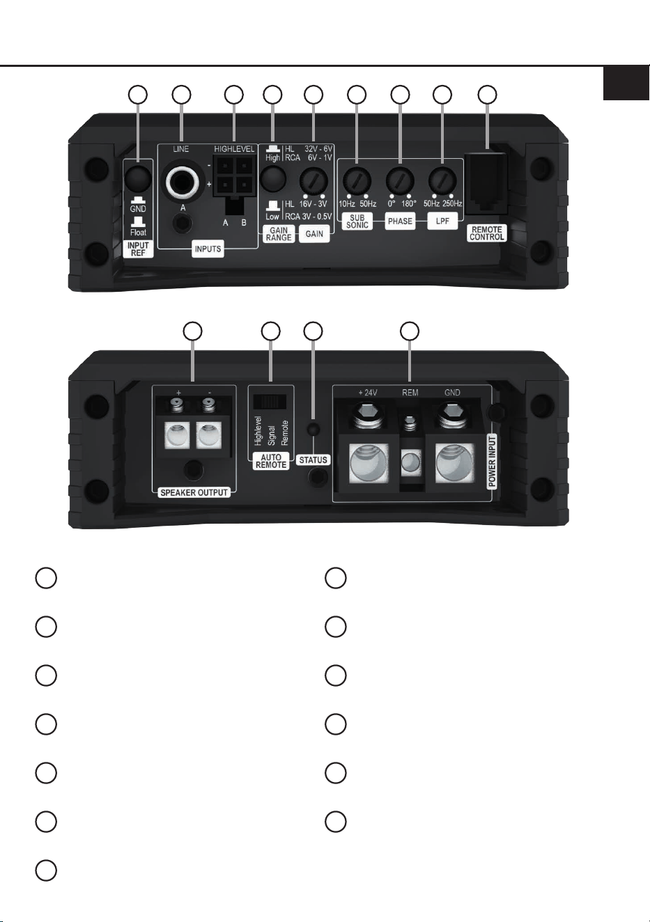
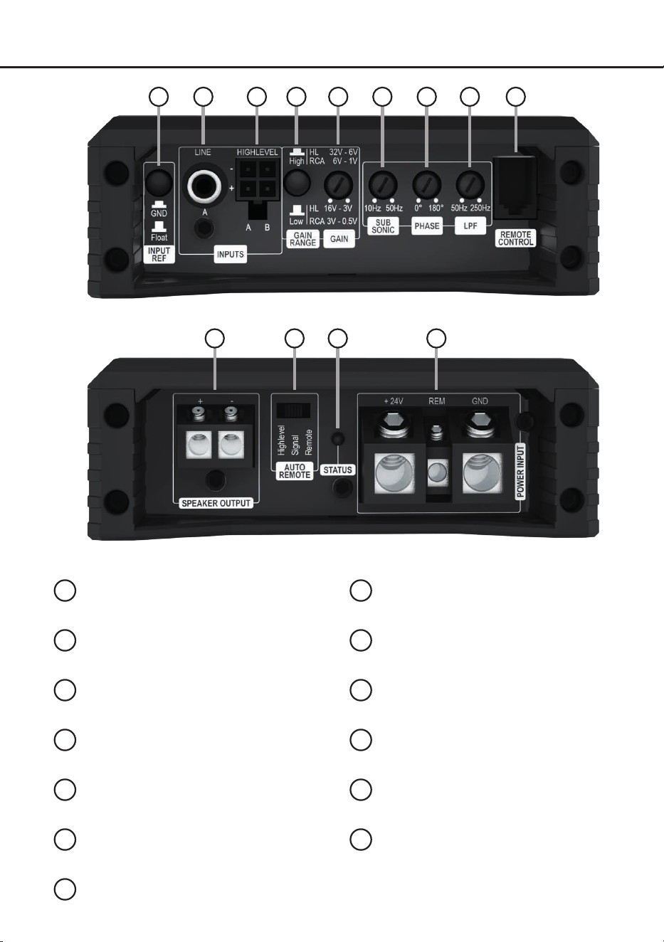
Anschluss- und Bedienelemente
1
3
82
1
Masseschalter
Seite 8, Punkt 12
2
Lowlevel-Vorverstärkereingang
Seite 5, Punkt 2
3
Highlevel-Lautsprechereingänge
Seite 5, Punkt 3
4
Gain Spannungsbereichs-Schalter
Seite 5, Punkt 1
5
Gain-Regler
Seite 6, Punkt 6
6
Subsonic-Regler
Seite 7, Punkt 8
7
Phasen-Regler
Seite 7, Punkt 9
8
Tiefpasslter-Regler (LPF)
Seite 7, Punkt 7
9
Fernbedienungseingang
Seite 8, Punkt 11
10
Lautsprecherausgang
Seite 7, Punkt 10
11
Auto Remote-Schalter
Seite 6, Punkt 4
12
Status LED
Seite 8, Punkt 1
13
Anschluss Stromversorgung & Remote
Seite 6, Punkt 5
7
1310 11
6
4 5 9
12
4
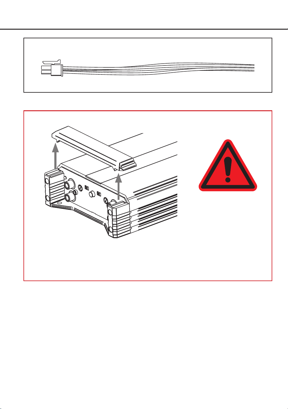
Hardware-Konguration
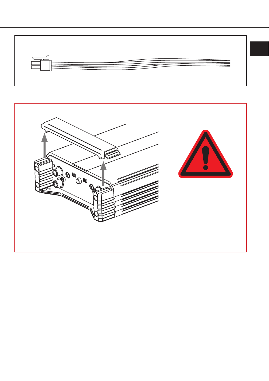
Abb. 1: Anschlusskabel Highlevel-Lautsprechereingänge A & B
Abb. 2: Abnehmen der Abdeckblende für vereinfachten Zugang zu den Anschluss- und Bedienelementen
Die Abdeckblende wird durch zwei starke Magneten sicher am Kühlkörper gehalten. Zum Entfernen
ziehen Sie die Blende einfach senkrecht nach oben ab. Nach Abschluss aller Anschlüsse und
Einstellungen setzen Sie die Blende wieder auf und achten darauf, dass sie korrekt und ohne
Verkanten sitzt.
ACHTUNG!
Heben sie das Gerät nicht
an den Abdeckblenden an
um Schäden zu vermeiden.

5
de
Kongurieren Sie den HELIX AMPLIFY
201 X-OVER in der nachfolgenden Reihenfolge
Achtung: Für die Durchführung der nachfol-
genden Schritte werden Spezialwerkzeuge und
Fachwissen benötigt. Um Anschlussfehler und
Beschädigungen zu vermeiden, fragen Sie im
Zweifelsfall Ihren Einbauspezialisten und beach-
ten Sie zwingend die allgemeinen Anschluss- und
Einbauhinweise (siehe Seite 2). Für einen bes-
seren Zugang zu den Anschluss- und Bedienele-
menten empehlt es sich, die Abdeckblenden des
Verstärkers, wie auf Seite 4 in Abb. 2 dargestellt,
zu entfernen.
1. Einstellung des Eingangsspannungsbe-
reichs
Um eine optimale Signal qualität sicherzustel-
len, muss der Eingangsspannungsbereich mit
dem Gain Spannungsbereichs-Schalter (Gain
Range, Seite 3, Punkt 4) an die Ausgangs-
spannung der angeschlossenen Signalquelle
angepasst werden, um Schäden am Verstär-
ker zu vermeiden.
Wir empfehlen, die maximale Ausgangsspan-
nung mithilfe eines geeigneten Messgeräts
zu ermitteln oder sich an Ihren autorisierten
HELIX Fachhändler zu wenden.
Wenn Sie unsicher sind, empfehlen wir, den
Schalter auf „High“ (Cinch 1 - 6 V / Highlevel
6 - 32 V) einzustellen, um mögliche Schäden
am Gerät zu vermeiden.
Low: Wählen Sie diese Einstellung für Stan-
dardanwendungen wie den Anschluss von:
- Audiotec Fischer DSP-Verstärkern über
Cinch-Kabel
- Original-Radios
- Aftermarket-Radios mit weniger als 3 V
RMS Ausgangsspannung
Der Eingangsspannungsbereich liegt hier
zwischen 0,5 und 3 Volt für den Lowlevel-Vor-
verstärkereingang sowie 3 und 16 Volt für den
Highlevel-Lautsprechereingang.
High: Wählen Sie diese Einstellung, wenn
Sie Geräte aus den folgenden Kategorien an-
schließen:
- Aftermarket-Radios mit mehr als 3 V RMS
Ausgangsspannung
- Premium Soundsystem-Verstärker mit
mehr als 50 W RMS Ausgangsleistung
- Stand-Alone DSPs mit mehr als 3 V RMS
Ausgangsspannung
Der Eingangsspannungsbereich liegt hier
zwischen 1 und 6 Volt für den Lowlevel-Vor-
verstärkereingang sowie 6 und 32 Volt für den
Highlevel-Lautsprechereingang.
2. Anschluss des Lowlevel-Vorverstärkerein-
gangs
Der Lowlevel-Vorverstärkereingang (Seite 3,
Punkt 2) kann mit einem entsprechenden Ka-
bel an den RCA / Cinch-Ausgang der Signal-
quelle (bspw. Radio / DSP / DSP-Verstärker)
angeschlossen werden. Die Eingangsemp-
ndlichkeit kann mit Hilfe des Gain-Reglers
optimal an die Signalquelle angepasst werden
(Seite 6, Punkt 6).
3. Anschluss der Highlevel-Lautsprecherein-
gänge
Die Hochpegel-Lautsprechereingänge A und
B (Seite 3, Punkt 3) können direkt mit den
Lautsprecherausgängen der Signalquelle
(bspw. Radio / DSP / DSP-Verstärker) mit
Hilfe entsprechender Kabel (Lautsprecherka-
bel mit max. 1 mm² Querschnitt) verbunden
werden.
Achten Sie bitte auf eine korrekte Polung!
Wenn Sie einen Anschluss verpolen, kann
dadurch die Funktion des Verstärkers beein-
trächtigt werden. Der Highlevel-Eingang ver-
fügt über den ADEP.3-Schaltkreis (Advanced
Diagnostics Error Protection der 3 Generati-
on), der dafür sorgt, dass der Verstärker auch
von OEM Radios als Lautsprecher erkannt
wird und somit im Werksradio keine Funkti-
onen deaktiviert werden und auch kein Ein-
trag im Fehlerspeicher des Fahrzeugs erzeugt
wird. Bei Verwendung dieses Eingangs schal-
tet der Verstärker bei allen handelsüblichen
Radios automatisch ein, so dass dieser nicht
über den Remote-Eingang (REM) eingeschal-
tet werden muss.
Achtung: Verwenden Sie zum Anschluss
ausschließlich das mitgelieferte Anschlusska-
bel (Seite 4, Abb.1).
Hardware-Konguration
6
4. Konguration der Einschaltautomatik (Au-
to-Remote)
Diese Einstellung ist nur erforderlich, wenn Sie
die Signalquelle am Highlevel-Lautsprecher-
eingang anschließen. Mit dem „Auto Remote“-
Schalter (Seite 3, Punkt 11) kann die automa-
tische Einschaltung des Verstärkers über den
Highlevel-Lautsprechereingang konguriert
oder deaktiviert werden. Dabei stehen fol-
genden Betriebs-Modi zur Auswahl:
Highlevel (Werkseinstellung): Der Verstär-
ker schaltet sich automatisch ein, sobald ein
Highlevel-Signal anliegt.
Signal: Der Verstärker wird in dieser Stellung
über das eigentliche Musiksignal ein- und
ausgeschaltet. Wählen Sie diese Einstellung,
wenn der Verstärker in der Einstellung „High-
level“ nicht zuverlässig eingeschaltet wird.
Remote: Die Einschaltung über den High-
level-Lautsprechereingang ist deaktiviert
und erfolgt ausschließlich über den Remote-
Eingang. Dies sollte vorgenommen werden,
wenn es beispielsweise zu Störgeräuschen
beim Ein- und Ausschalten des Verstärkers
kommt. In diesem Fall muss der Remote-Ein-
gang (Seite 6, Punkt 5) belegt werden.
5. Anschluss der Stromversorgung & Remote
Vor dem Anschluss des +24 V
Versorgungskabels an das Bordnetz muss
die Autobatterie abgeklemmt werden.
Achten Sie unbedingt auf eine korrekte Pola-
rität.
+24 V: Anschluss für die Plusleitung.
Das +24 V Stromkabel ist am Pluspol der Bat-
terie anzuschließen. Die Plusleitung sollte in
einem Abstand von max. 30 cm von der Bat-
terie mit einer Hauptsicherung abgesichert
werden. Der Wert der Sicherung errechnet
sich aus der maximalen Stromaufnahme der
gesamten Car-Hi Anlage (201 X-OVER =
max. 40 A bei 24 V Bordnetz). Verwenden
Sie bei kurzen Leitungen (< 1 m) einen Quer-
schnitt von mindestens 10 mm². Bei längeren
Leitungen empfehlen wir einen Querschnitt
von 16 mm² bis 25 mm².
GND: Anschluss für die Masseleitung. Das
Massekabel muss an einer nicht isolierten
Stelle mit dem Kfz-Chassis oder direkt mit
dem Minuspol der Autobatterie verbunden
werden. Der Kabelquerschnitt sollte den glei-
chen Durchmesser wie die Plusleitung haben.
Ein nicht ausreichender Massekontakt führt
zu unerwünschten Störgeräuschen und Fehl-
funktionen.
REM: Der Remote-Eingang dient zum Ein-
und Ausschalten des Verstärkers. Dieser wird
mit dem Remote-Ausgang der unmittelbar
vorgeschalteten Komponente, welche das
Eingangssignal für die 201 X-OVER liefert,
verbunden. Der Eingang muss nicht belegt
werden, wenn der Highlevel-Lautsprecherein-
gang benutzt wird. Es wird dringend davon
abgeraten, den Remote-Eingang des Verstär-
kers über das Zündungsplus des Fahrzeugs
zu steuern, um Störgeräusche beim Ein- und
Ausschalten zu vermeiden.
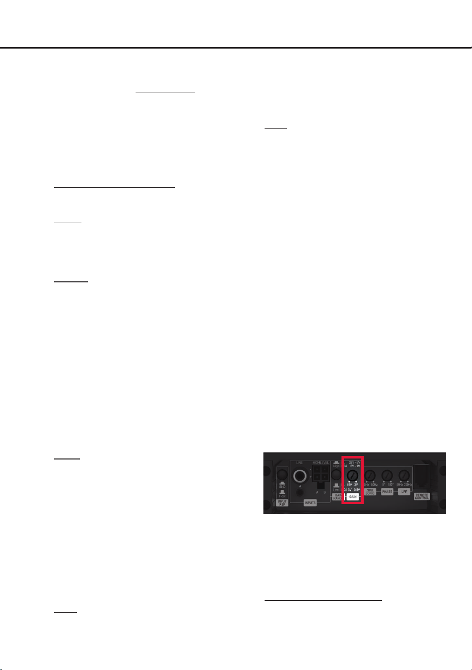
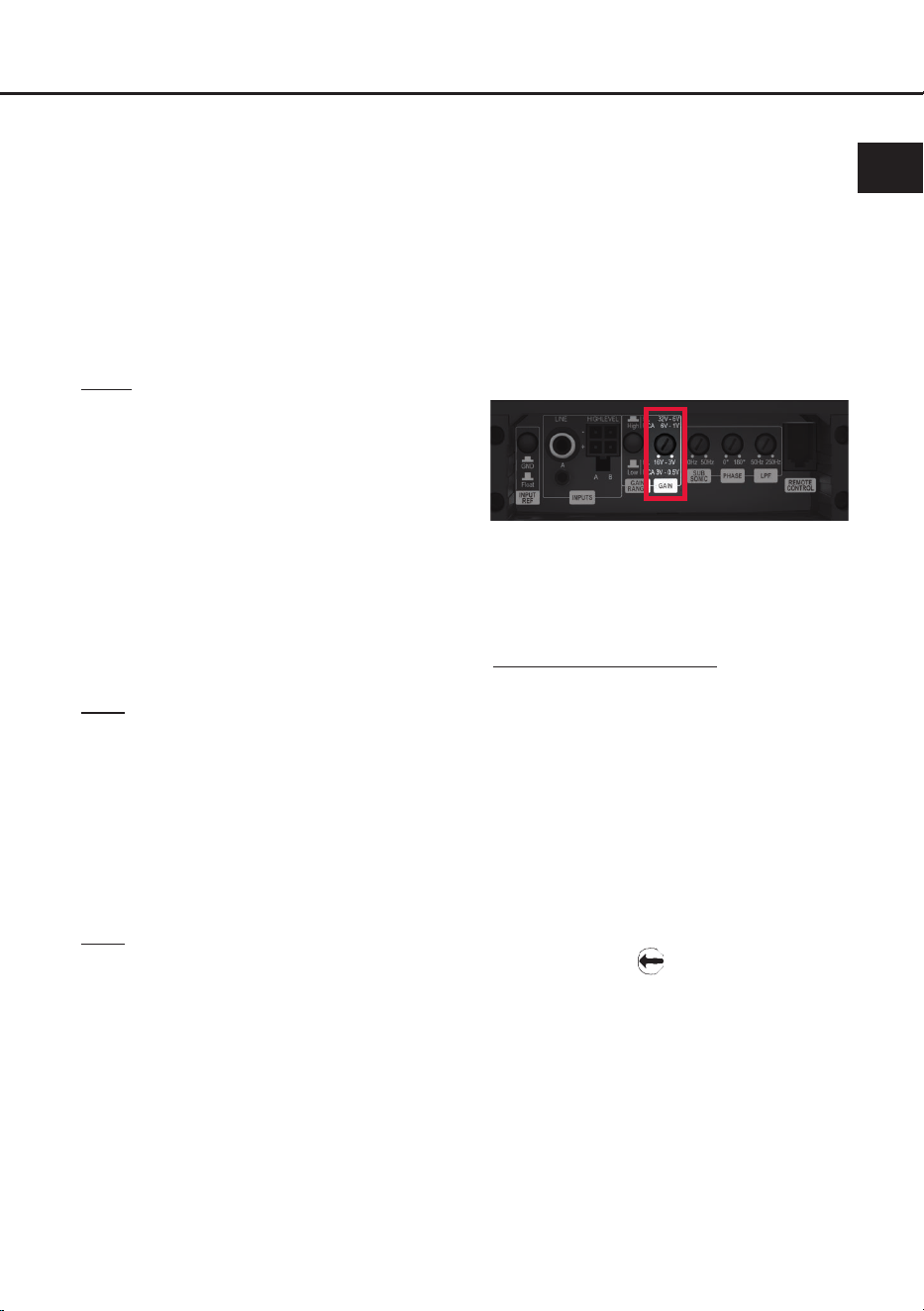
6. Einstellen der Eingangsempndlichkeit
ACHTUNG: Es ist zwingend notwendig,
die Eingangsempndlichkeit der AMPLIFY
201 X-OVER an die Signalquelle anzupas-
sen, um eine bestmögliche Signalqualität
zu garantieren und Schäden am Verstärker
zu vermeiden. Außerdem ist es zuvor
zwingend erforderlich den Eingangsspan-
nungsbereich an die Ausgangsspannung
Ihrer Signalquelle anzupassen (Seite 5,
Punkt 1).
Mit Hilfe des Gain-Reglers (Seite 3, Punkt 5)
kann die Eingangsempndlichkeit optimal an
die Signalquelle angepasst werden.
Dieser Regler ist kein Lautstärkeregler, son-
dern dient nur der Anpassung. Die Einstellung
des Reglers beeinusst sowohl den Vorver-
stärkereingang als auch die Highlevel-Ein-
gänge!
Die Gain-Regelbereiche sind:
Eingangsspannungsbereich „Low“:
Highlevel: 3 - 16 Volt
Cinch: 0,5 - 3 Volt
Hardware-Konguration
7
de
Eingangsspannungsbereich „High“:
Highlevel: 6 - 32 Volt
Cinch: 1 - 6 Volt
Sofern die Lautsprecherausgänge eines üb-
lichen Radios verwendet werden (Highlevel),
empfehlen wir eine Einstellung von ca. 9 Volt.
Dafür stellen Sie den Regler vom Linksan-
schlag aus im Uhrzeigersinn etwa auf die
9 Uhr-Position ein.
Sollten Sie sich bzgl. der Ausgangsspannung
Ihrer Signalquelle nicht sicher sein, kontaktie-
ren Sie Ihren HELIX Fachhändler.
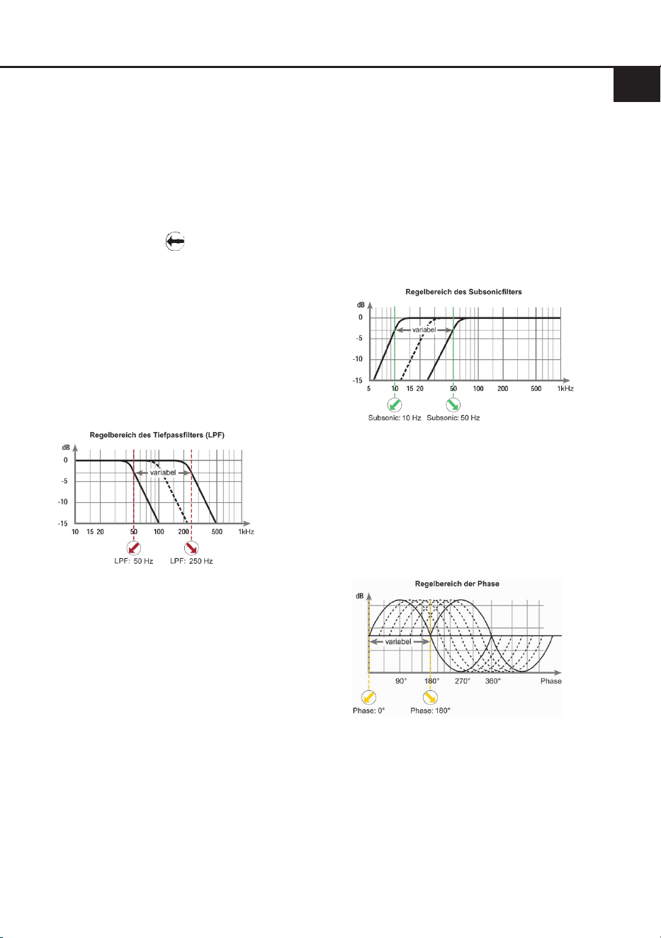
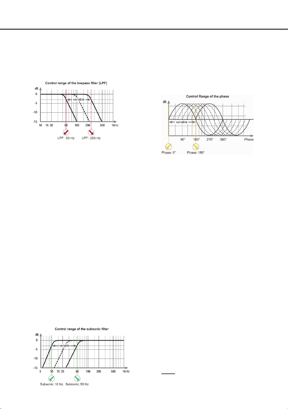
7. Tiefpasslter (Lowpass) einstellen
Mit Hilfe des Tiefpasslter-Reglers (Seite 3,
Punkt 8) kann das Tiefpasslter von 50 Hz bis
250 Hz eingestellt werden. Dieser Regler ist
immer aktiv und muss zwingend eingestellt
werden.
Das Tiefpasslter bildet in Verbindung mit
dem Subsoniclter (Seite 7, Punkt 8) in jedem
Fall einen Bandpass. So kann mit Hilfe dieser
beiden Regler ein Bandpass von 10 Hz bis
250 Hz gebildet werden.
Achtung: Bitte vergewissern Sie sich, dass
beim Einstellen eines Bandpasses die Über-
nahmefrequenzen von Subsonic- und Tief-
passlter mindestens zwei Oktaven aus-
einander liegen, um einen Pegelverlust zu
vermeiden! Das heißt: Wird das Tiefpasssi-
gnal z.B. auf 100 Hz eingestellt, so sollte der
Subsoniclter um mindestens zwei Oktaven
tiefer auf ca. 25 Hz eingestellt werden. (1 Ok-
tave = Frequenzverdopplung oder Frequenz-
halbierung).
8. Subsonic einstellen
Das Subsonic-Filter dient dazu, sehr tiefe
Frequenzen außerhalb des Hörspektrums he-
rauszultern und so den Subwoofer und den
Verstärker zu entlasten, um mehr Leistung für
die wahrnehmbaren Frequenzen zur Verfü-
gung zu haben.
Mit Hilfe des Subsonic-Reglers (Seite 3,
Punkt 6) kann der Subsoniclter von 10 Hz
bis 50 Hz eingestellt werden.
Dieser Regler ist immer aktiv und muss zwin-
gend eingestellt werden.
9. Phasenlage einstellen
Die Einstellung der Phasenlage ermöglicht
eine bessere Ankopplung des Subwoofers
an die Tieftonwiedergabe der restlichen Laut-
sprechersysteme und verhindert ein Auslö-
schen der tiefen Frequenzen.
Mit Hilfe des Phasen-Reglers (Seite 3,
Punkt 7) kann die Phase von 0° bis 180° ein-
gestellt werden.
10. Anschluss des Lautsprecherausgangs
Der Lautsprecherausgang kann direkt mit den
Lautsprecherleitungen verbunden werden.
Verbinden Sie niemals die Lautsprecherlei-
tungen mit der Kfz-Masse (Fahrzeugkaros-
serie). Dieses kann Ihren Verstärker und Ihre
Lautsprecher zerstören.
Achten Sie darauf, dass alle Lautsprecher-
systeme phasenrichtig angeschlossen sind,
d.h. Plus zu Plus und Minus zu Minus. Ver-
tauschen von Plus und Minus hat einen To-

8
Hardware-Konguration
talverlust der Basswiedergabe zur Folge. Der
Pluspol ist bei den meisten Lautsprechern ge-
kennzeichnet.
Die Impedanz darf 1 Ohm nicht unterschreiten,
da sonst die Schutzschaltung des Verstärkers
aktiviert wird. Beispiele für den Lautsprecher-
anschluss nden Sie auf Seite 9 f.
11. Optional: Anschluss Kabelfernbedienung
Schließen Sie die im Lieferumfang enthaltene
Kabelfernbedienung an den Fernbedienungs-
eingang an (Seite 3, Punkt 9). Mit Hilfe dieser
Fernbedienung lässt sich die Lautstärke des
Subwoofers kontrollieren.
12. Optional: Konguration der Masseanbin-
dung
In bestimmten Fällen kann es notwendig sein,
die Signalmasse der Signaleingänge anzu-
passen. Dies geschieht über den Masseschal-
ter (Seite 3, Punkt 1)
Float: In dieser Schalterstellung wird die
Signalmasse durch einen Dierenzverstärker
von der Bordnetzmasse getrennt.
Dies ist in den meisten Fahrzeugen die opti-
male Einstellung, um Störgeräusche, wie z. B.
von der Lichtmaschine, zu vermeiden.
GND: Die Signalmasse des Eingangs wird di-
rekt mit der Bordnetzmasse verbunden. Diese
Einstellung sollte gewählt werden, wenn bei
der Schalterstellung „Float“ Störgeräusche
auftreten.
Weitere Funktionen
1. Status LED
Die Status LED (Seite 3, Punkt 12) zeigt den
Betriebszustand des Verstärkers an.
Grün: Verstärker eingeschaltet und betriebsbe-
reit.
Rot: Protection Mode aktiv. Dieser kann unter-
schiedliche Ursachen haben. Der Verstärker
ist mit Schutzschaltungen gegen Über- und
Unterspannung sowie Überhitzung ausgestat-
tet. Prüfen Sie in diesem Fall alle Anschlüsse
auf Fehler, wie z.B. Kurzschlüsse oder feh-
lerhafte Verbindungen. Ist die Sicherheits-
schaltung der Temperaturüberwachung aktiv,
wird die Signalausgabe abgeschaltet, bis ein
sicherer Betrieb wieder gewährleistet werden
kann.
Sollte sich der Verstärker nach Beseitigung
der Fehlerquelle nicht wieder einschalten
lassen, liegt ein Defekt vor und er muss zur
Reparatur eingeschickt werden. Wenden
Sie sich hierzu an einen autorisierten HELIX
Händler vor Ort.
9
de
Kongurationsbeispiele
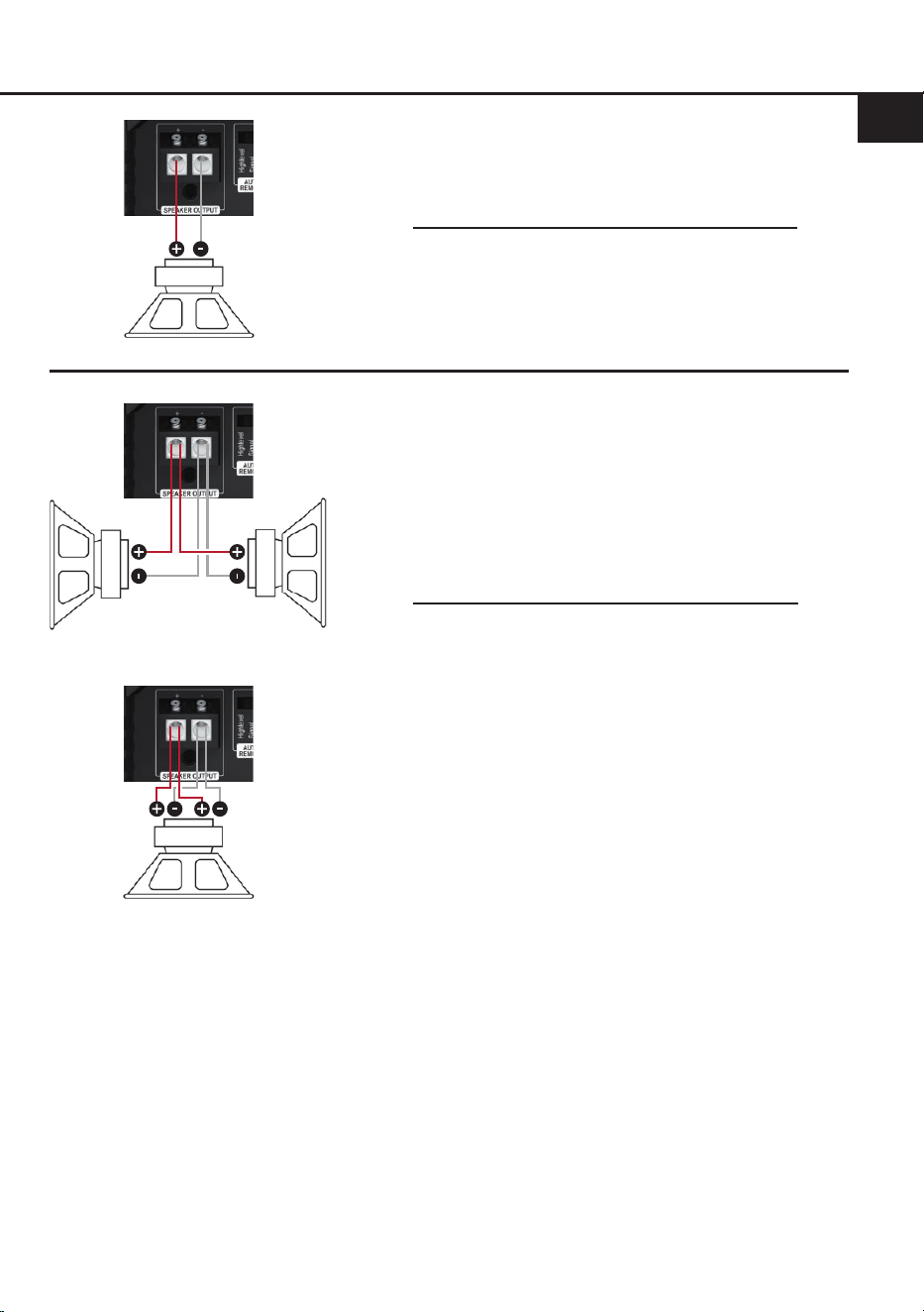
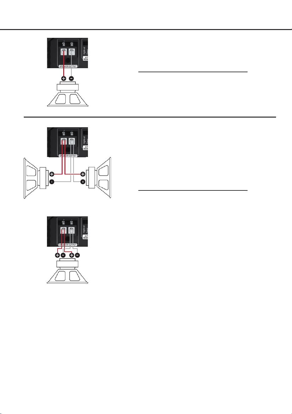
Mono
Subwoofer mit einer Schwingspule (Single Voice Coil)
Maximale Ausgangsleistung dieser Konguration:
1 x 4 Ohm: 250 Watt RMS
1 x 2 Ohm: 450 Watt RMS
1 x 1 Ohm: 750 Watt RMS
Parallelbetrieb
Zwei Subwoofer mit einer Schwingspule (Single Voice
Coil) oder ein Subwoofer mit Doppelschwingspule (Dual
Voice Coil) werden parallel geschaltet.
Hinweis: Die Parallelschaltung von zwei Schwingspulen
führt zur Halbierung der Impedanz!
Maximale Ausgangsleistung dieser Konguration:
Zwei Subwoofer mit 1 x 4 Ohm entsprechen einer
Gesamtimpedanz von 2 Ohm: 450 Watt RMS
Ein Subwoofer mit 2 x 4 Ohm entspricht ebenso einer
Gesamtimpedanz von 2 Ohm: 450 Watt RMS
Zwei Subwoofer mit 1 x 2 Ohm entsprechen einer
Gesamtimpedanz von 1 Ohm: 750 Watt RMS
Ein Subwoofer mit 2 x 2 Ohm entspricht ebenso einer
Gesamtimpedanz von 1 Ohm: 750 Watt RMS
Hinweis: Das Parallelschalten von 1 Ohm Schwingspu-
len führt zu Abschaltung des Verstärkers.
Zwei Subwoofer mit einer
Schwingspule
(Single Voice Coil)
Ein Subwoofer mit
Doppelschwingspule
(Dual Voice Coil)
10
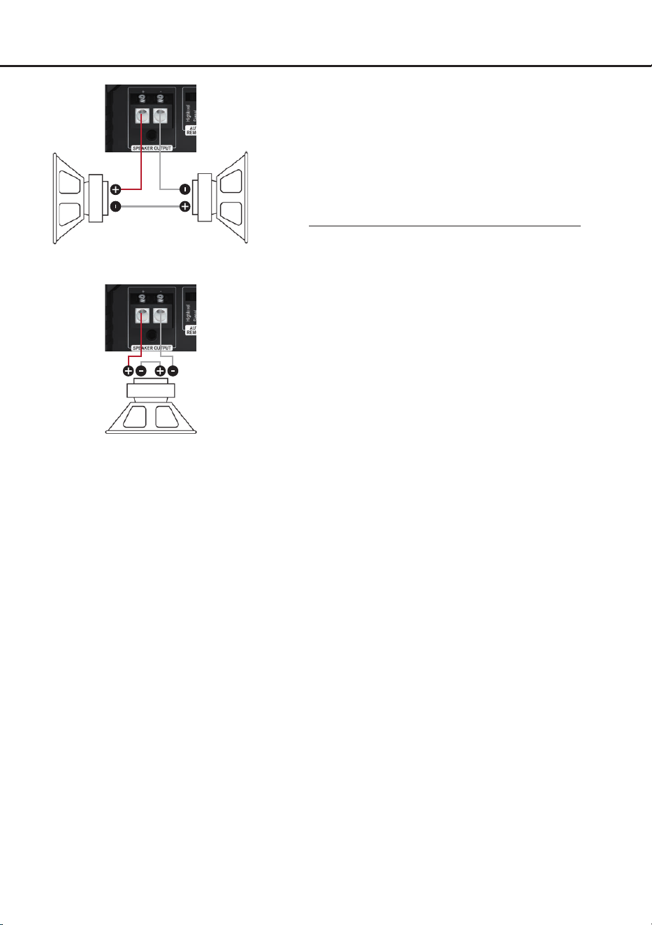
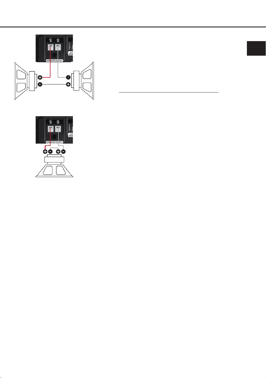
Reihenbetrieb
Zwei Subwoofer mit einer Schwingspule (Single Voice
Coil) oder ein Subwoofer mit Doppelschwingspule (Dual
Voice Coil) werden in Reihe geschaltet.
Hinweis: Die Reihenschaltung von zwei Schwingspulen
führt zur Verdopplung der Impedanz!
Maximale Ausgangsleistung dieser Konguration:
Zwei Subwoofer mit 1 x 2 Ohm entsprechen einer
Gesamtimpedanz von 4 Ohm: 250 Watt RMS
Ein Subwoofer mit 2 x 2 Ohm entspricht ebenso einer
Gesamtimpedanz von 4 Ohm: 250 Watt RMS
Zwei Subwoofer mit 1 x 1 Ohm entsprechen einer
Gesamtimpedanz von 2 Ohm: 450 Watt RMS
Ein Subwoofer mit 2 x 1 Ohm entspricht ebenso einer
Gesamtimpedanz von 2 Ohm: 450 Watt RMS
Hinweis: Die Reihenschaltung von 4 Ohm Sub woofern
führt zu einer sehr geringen Ausgangsleistung des
Verstärkers und ist daher nicht empfehlenswert!
Hinweis: Der Minuspol der ersten Schwingspule muss
mit dem Pluspol der zweiten Schwingspule verbunden
werden. Hierzu sollte derselbe Kabelquerschnitt gewählt
werden, welcher auch für den Anschluss des Subwoo-
fers genutzt wird.
Ein Subwoofer mit
Doppelschwingspule
(Dual Voice Coil)
Zwei Subwoofer mit einer
Schwingspule
(Single Voice Coil)
Kongurationsbeispiele

11
de
Technische Daten
Leistung RMS (≤ 1% THD+N @ 28,8 V)
- @ 4 Ohm .................................................................... 1 x 250 Watt
- @ 2 Ohm .................................................................... 1 x 450 Watt
- @ 1 Ohm .................................................................... 1 x 750 Watt*
Max. Leistung ............................................................... Bis zu 850 Watt RMS @ 1 Ohm
Verstärkertechnologie ...................................................Class D
Eingänge ...................................................................... 1 x Cinch
2 x Hochpegel-Lautsprechereingang
1 x Remote In (12 - 32 Volt)
1 x Fernbedienungseingang
Eingangsempndlichkeit ............................................... Cinch: 0,5 - 6 Volt
Hochpegel: 3 - 32 Volt
Eingangsimpedanz ....................................................... Cinch: 8 kOhm
Hochpegel: 9 - 33 Ohm
Ausgänge ..................................................................... 1 x Lautsprecherausgang
Frequenzbereich...........................................................10 Hz - 250 Hz
Tiefpass ........................................................................50 - 250 Hz regelbar
Subsonic .......................................................................10 - 50 Hz regelbar
Phase ...........................................................................0° - 180° regelbar
Flankensteilheit............................................................. Tiefpass: 12 dB/Okt.
Subsonic: 12 dB/Okt.
Signal- / Rauschabstand (A-bewertet)..........................114 dB @ Maximalleistung
Klirrfaktor (THD @ 100 Hz, 1 W an 4 Ohm) .................< 0,003 %
Klirrfaktor (THD+N @ 100 Hz, 1 W an 4 Ohm) ............< 0,02 %
Dämpfungsfaktor ..........................................................200
Betriebsspannung.........................................................21 - 32 Volt (max. 5 Sek. bis hinab zu 12 Volt)
Leerlaufstromaufnahme................................................550 mA
Sicherung .....................................................................2 x 15 A LP-Mini-Stecksicherung
Leistungsaufnahme ......................................................DC 24 V 40 A max.
Umgebungstemperaturbereich für den Betrieb ............-40 °C bis +70 °C
Zusätzliche Features .................................................... Aktive, regelbare Frequenzweiche, Start-Stop-
fähigkeit, Highlevel-Eingang mit automatischer
Einschaltung, ADEP.3
Abmessungen (H x B x T) ............................................40 x 248 x 114 mm
* Dauerhafte 1 Ohm Leistung nur mit Musiksignal erreicht
12
Die Garantieleistung entspricht der gesetzlichen Regelung. Von der Garantieleistung ausgeschlossen
sind Defekte und Schäden, die durch Überlastung oder unsachgemäße Behandlung entstanden sind.
Eine Rücksendung kann nur nach vorheriger Absprache in der Originalverpackung, einer detaillierten
Fehlerbeschreibung und einem gültigen Kaufbeleg erfolgen. Technische Änderungen, Druckfehler und
Irrtümer vorbehalten!
Für Schäden am Fahrzeug oder Gerätedefekte, hervorgerufen durch Bedienungsfehler des Gerätes,
können wir keine Haftung übernehmen.
Garantiehinweis
Dieses Produkt ist mit einer CE-Kennzeichnung versehen. Damit ist das Gerät für den Be-
trieb in Fahrzeugen innerhalb der Europäischen Union (EU) zertiziert.
Dieses Symbol bedeutet, dass das Produkt nicht über den Hausmüll entsorgt werden darf,
sondern bei einer entsprechenden Sammelstelle zum Recycling abgegeben werden muss.
Befolgen Sie die örtlichen Vorschriften und entsorgen Sie das Produkt niemals mit dem nor-
malen Hausmüll. Die ordnungsgemäße Entsorgung von Altgeräten trägt zur Vermeidung
von Umwelt- und Gesundheitsschäden bei.
Dieses Produkt ist mit einer UKCA-Kennzeichnung versehen. Damit ist das Gerät für den
Betrieb in Fahrzeugen innerhalb des Vereinigten Königreichs zertiziert.
Dieses Produkt ist mit einer EAC-Kennzeichnung versehen. Damit ist das Gerät für den
Betrieb in Fahrzeugen innerhalb der Eurasian Customs Union zertiziert.
Hinweise zur Entsorgung
Regulatorische Hinweise

13
en
General installation instructions for HELIX
components
To prevent damage to the unit and possible injury,
read this manual carefully and follow all installa-
tion instructions. This product has been checked
for proper function prior to shipping and is guaran-
teed against manufacturing defects.
Before starting your installation, disconnect
the battery’s negative terminal to prevent dam-
age to the unit, re and / or risk of injury. For
a proper performance and to ensure full warran-
ty coverage, we strongly recommend to get this
product installed by an authorized HELIX dealer.
Install your AMPLIFY 201 X-OVER in a dry loca-
tion with sucient air circulation for proper cooling
of the equipment. The amplier should be secured
to a solid mounting surface using proper mounting
hardware. Before mounting, carefully examine the
area around and behind the proposed installation
location to insure that there are no electrical ca-
bles or components, hydraulic brake lines or any
part of the fuel tank located behind the mounting
surface. Failure to do so may result in unpredict-
able damage to these components and possible
costly repairs to the vehicle.
General instruction for connecting the HELIX
AMPLIFY 201 X-OVER amplier
The AMPLIFY 201 X-OVER amplier may only be
installed in motor vehicles which have a 24 Volts
negative terminal connected to the chassis
ground. Any other system could cause damage
to the amplier and the electrical system of the
vehicle.
The positive cable from the battery for the entire
sound system should be provided with a main fuse
at a distance of max. 30 cm from the battery. The
value of the fuse is calculated from the maximum
total current draw of the car audio system.
Use only suitable cables with sucient ca-
ble cross-section for the connection of the
AMPLIFY 201 X-OVER. The fuses of the ampli-
er may only be replaced by identically rated
fuses (2 x 15 A) to avoid damage of the ampli-
er.
Prior to installation, plan the wire routing to
avoid any possible damage to the wire harness.
All cabling should be protected against possible
crushing or pinching hazards. Also avoid routing
cables close to potential noise sources such as
electric motors, high power accessories and other
vehicle harnesses.
Congratulations!
General instructions
Dear Customer,
Congratulations on your purchase of this innova-
tive and high-qual ity HELIX product.
Thanks to more than 35 years of experience in
research and development of audio products
this amplier sets new standards in the range of
ampliers.
We wish you many hours of enjoyment with your
new HELIX AMPLIFY 201 X-OVER.
Yours,
AUDIOTEC FISCHER
14
Connectors and control units
1
Input reference pushbutton
Page 18, point 12
2
Lowlevel line input
Page 16, point 2
3
Highlevel speaker inputs
Page 16, point 3
4
Gain range pushbutton
Page 16, point 1
5
Gain control
Page 17, point 6
6
Subsonic control
Page 18, point 8
7
Phase control
Page 18, point 9
8
Lowpass lter control (LPF)
Page 18, point 7
9
Remote control input
Page 18, point 11
10
Speaker output
Page 18, point 10
11
Auto remote switch
Page 16, point 4
12
Status LED
Page 19, point 1
13
Power & Remote connector
Page 17, point 5
1
3
82 7
1310 11
6
4 5 9
12
15
en
Hardware conguration
Fig. 2: Removal of cover panel for easier access to connectors and control units
Two strong magnets securely attach the cover panel to the heatsink. To remove it, simply pull the
panel vertically upward. After completing all connections and settings, reattach the panel, ensuring it
is properly aligned and seated without tilting.
Fig. 1: Connection cable for highlevel speaker inputs A & B
CAUTION!
Do not lift the device by
the cover panels to avoid
damage.

16
Hardware conguration
Congure the HELIX AMPLIFY 201 X-OVER as
follows
Caution: Carrying out the following steps will
require special tools and technical knowledge. In
order to avoid connection mistakes and / or dam-
age, ask your dealer for assistance if you have any
questions and follow all instructions in this manual
(see page 13). It is recommended that this unit will
be installed by an authorized HELIX dealer.
For better access to the connectors and control
units, we recommend to remove the amplier’s
cover panels, as shown on page 15, g. 2.
1. Adjusting input voltage range
To ensure optimal signal quality, the input
voltage range must be adjusted to the output
voltage of the connected signal source using
the gain range pushbutton (page 14, point 4)
to prevent damage to the amplier.
We recommend measuring the maximum out-
put voltage using an appropriate measuring
device or contacting your authorized HELIX
dealer.
If you are unsure, we recommend setting the
pushbutton to “High” (RCA / Cinch 1 - 6 V /
Highlevel 6 - 32 V) to avoid potential damage
to the device.
Low: Select this setting for standard applica-
tions, such as connecting:
- Audiotec Fischer DSP ampliers using
RCA cables
- Factory radios
- Aftermarket radios with an output voltage
of less than 3 V RMS
In this mode the input voltage range is 0.5
to 3 Volts for the lowlevel line input and 3 to
16 Volts for the highlevel speaker input.
High: Select this setting when connecting de-
vices from the following categories:
- Aftermarket radios with an output voltage
exceeding 3 V RMS
- Premium sound system ampliers with
an output power of more than 50 W RMS
- Stand-alone DSPs with an output voltage
exceeding 3 V RMS
The input voltage range in this mode is 1 to
6 Volts for the lowlevel line input and 6 to
32 Volts for the highlevel speaker input.
2. Connecting the pre-amplier input
The lowlevel line input (page 14, point 2) can
be connected to signal sources such as head
units, radios, DSPs and DSP ampliers using
an appropriate cable. The input sensitivity can
be optimally adapted to the signal source us-
ing the gain control (page 17, point 6).
3. Connecting the highlevel speaker inputs
The highlevel loudspeaker inputs A and B
(page 14, point 3) can be connected direct-
ly to the loudspeaker outputs of the signal
source (e.g., head units, radios, DSPs, DSP
ampliers) using appropriate cables (loud-
speaker cables with 1 mm² / AWG 18 max.).
Make sure that the polarity is correct. If one
or more connections have reversed polarity it
may aect the performance of the amplier.
The Highlevel Input is equipped with our pro-
prietary ADEP.3 circuit (Advanced Diagnostics
Error Protection 3rd generation) which en-
sures that the car radio detects the amplier
as a speaker and thus neither any function
of the radio (e.g. fader) will be deactivated
nor any error log in the CPU of the car will
be created. If this input is used, the remote
input (REM) does not need to be connected,
as the amplier will automatically turn on once
a loudspeaker signal is applied.
Attention: Solely use the supplied connec-
tion cable for connecting the highlevel inputs
(page 15, g. 1)!
4. Conguration of the automatic turn-on
( Auto-Remote)
This setting is only required when connecting
the signal source using highlevel signals.
The auto remote switch (page 14, point 11)
allows you to congure or deactivate the am-
plier’s automatic turn-on feature when using
the highlevel input. There are three available
modes:
Highlevel (default setting): The amplier au-
tomatically turns on as soon as a highlevel
signal is detected.
Signal: In this position, the amplier is
switched on and o by the actual music signal.
Select this mode if the amplier does not reli-
ably turn on in “Highlevel” position.
Remote: The automatic turn-on via the high-
17
en
level input is disabled, and the amplier will
only turn on via the remote input. This setting
is recommended if there are e.g. noises while
switching on / o the amplier. In this case,
the remote input (page 17, point 5) must be
connected.
5. Connection to power supply & remote
Make sure to disconnect the battery before
installing the AMPLIFY 201 X-OVER.
Ensure correct polarity.
+24 V: Connector for the positive cable.
Connect the +24 V power cable to the positive
terminal of the battery. The positive wire from
the battery to the ampliers power terminal
needs to have an inline fuse at a distance of
no more than 12 inches (30 cm) from the bat-
tery. The value of the fuse is calculated from
the maximum total current input of the whole
car audio system (201 X-OVER = max. 40 A
at 24 V power supply). If your power wires are
short (less than 1 m / 40”) then a wire gauge of
10 mm² / AWG 8 will be sucient. In all other
cases we strongly recommend gauges of 16 -
25 mm² / AWG 6 – 4!
GND: Connector for the ground cable. The
ground wire should be connected to a com-
mon ground reference point (this is located
where the negative terminal of the battery is
grounded to the metal body of the vehicle) or
to a prepared metal location on the vehicle
chassis, i.e., an area cleaned of all paint resi-
dues. The cable should have the same gauge
as the +24 V wire. Inadequate grounding
causes audible interference and malfunctions.
REM:
The remote input is used to switch on
and o the amplier. It is mandatory to connect
this input to the remote output of the precon
-
nected device that provides the input signal to
the AMPLIFY 201 X-OVER.
This input does
not need to be assigned if a highlevel signal
is used.
We do not recommend controlling the remote
input via the ignition switch to avoid pop noise
during turn on / o.
6. Adjustment of the input sensitivity
ATTENTION: It is mandatory to properly
adapt the input sensitivity of the AMPLIFY
201 X-OVER to the signal source to achieve
the best possible signal quality and avoid
damage to the amplier. It is also manda-
tory to adjust the input voltage range to
the output voltage of your signal source
(page 16, point 1).
The input sensitivity can be optimally adapted
to the signal source using thee gain control
(page 14, point 5).
This is not a volume control; it’s solely for ad-
justing the amplier´s gain.
The setting of the control aects both the low-
level line input and highlevel input.
The Gain control ranges are:
Input voltage range “Low”:
Highlevel: 3 - 16 Volts
RCA / Cinch: 0.5 - 3 Volts
Input voltage range “High”:
Highlevel: 6 - 32 Volts
RCA / Cinch: 1 - 6 Volts
If the speaker outputs (highlevel) of a conven-
tional radio are used we recommend an input
sensitivity of roughly 9 Volts. For this purpose,
turn the control from max. CCW position to
9 o’clock position.
If you are not sure regarding the signal
source’s output voltage, please contact your
HELIX specialist dealer.
18
Hardware conguration
7. Adjusting the lowpass lter
The crossover frequency of the lowpass lter
can be adjusted from 50 Hz to 250 Hz using
the lowpass lter control (page 14, point 8).
This control is always activated and its adjust-
ment is mandatory.
In combination with the subsonic lter
(page 18, point 8), the lowpass lter creates
a bandpass in any case. By adjusting the
subsonic and lowpass lter any bandpass be-
tween 10 Hz and 250 Hz can be realized.
Caution: To avoid a loss of gain make sure
that the crossover frequencies of the subsonic
and lowpass lters do have an interval of at
least two octaves when generating a band-
pass. That means if the lowpass is adjusted
to 100 Hz the subsonic should be adjusted to
25 Hz or less (one octave = doubled frequen-
cy or halved frequency).
8. Adjusting the subsonic
The subsonic lter cuts o very low frequen-
cies which aren’t audible and therefore re-
lieves the amplier and also the subwoofer.
Additionally the amplier will have more power
available for the audible frequencies.
The crossover frequency of the subsonic lter
can be adjusted from 10 Hz to 50 Hz using the
subsonic control (page 14, point 6).
This control is always activated and its adjust-
ment is mandatory.
9. Adjusting the phase
The phase adjustment allows to match the
subwoofer with the low frequency reproduc-
tion of the other speakers thus avoiding any
cancellations in the frequency response due
to phase shifts.
Using the phase control (page 14, point 7),
the phase can be adjust from 0° to 180°.
10. Connecting the loudspeaker output
The loudspeaker output can be connect-
ed directly to the wires of the loudspeakers.
Never connect any of the loudspeaker cables
with the chassis ground as this will damage
your amplier and your speakers. Ensure that
the loudspeakers are correctly connected (in
phase), i.e., plus to plus and minus to minus.
Exchanging plus and minus causes a total
loss of bass reproduction. The plus pole is in-
dicated on most speakers.
The impedance must not be less than 1 Ohm,
otherwise the amplier protection will be ac-
tivated. Examples for speaker congurations
can be found on page 20 f.
11. Optional: Connecting the remote control
Connect the cable remote control that is in-
cluded in the scope of delivery to the remote
control input (page 14, point 9) The remote
control can be used to adjust the volume of
the subwoofer.
12. Optional: Conguration of the input refer-
ence
In some cases, it may be necessary to adjust
the signal ground of the signal inputs.
This can be done using the input reference
pushbutton (page 14, point 1).
Float: In this switch position, the signal ground
is separated from the vehicle’s ground by a
dierential amplier. This is usually the best
setting in most vehicles to prevent interfer-

19
en
1. Status LED
The Status LED (page 14, point 12) indicates
the operating mode of the amplier.
Green: The amplier is ready for operation.
Red: Protection Mode active. A malfunction
has occurred that may have dierent root
causes. The amplier is equipped with protec-
tion circuits against over- and undervoltage
as well as overheating. Please check for con-
necting failures such as short-circuits or other
incorrect connections. If the amplier is over-
heated, the internal temperature protection
will turn o the signal output until it reaches a
safe temperature level again. If the amplier
does not turn on, it is defective and needs to
be sent to your local authorized HELIX dealer
for repair service.
Additional functions
ence noise, e.g. from the alternator.
GND: The signal ground is tied together with
the vehicle’s ground. This setting should be
selected if noise occurs in the “Float” position.
20
Conguration examples
Parallel operation
Two subwoofers with one voice coil (single voice coil)
or one subwoofer with dual voice coil are connected in
parallel.
Note: The parallel connection of two voice coils will
result in halving the impedance!
Maximum output power of this conguration:
Two subwoofers with 1 x 4 Ohms correspond to a total
impedance of 2 Ohms: 450 Watts RMS
One subwoofer with 2 x 4 Ohms also corresponds to a
total impedance of 2 Ohms: 450 Watts RMS
Two subwoofers with 1 x 2 Ohms correspond to a total
impedance of 1 Ohm: 750 Watts RMS
One subwoofer with 2 x 2 Ohms also corresponds to a
total impedance of 1 Ohm: 750 Watts RMS
Note: The parallel connection of 1 Ohm voice coils will
result in shutdown of the amplier.
Mono
Subwoofer with one voice coil (single voice coil)
Maximum output power of this conguration:
1 x 4 Ohms: 250 Watts RMS
1 x 2 Ohms: 450 Watts RMS
1 x 1 Ohm: 750 Watts RMS
Two subwoofers with
a single voice coil
One subwoofer with
a dual voice coil
21
en
In series
Two subwoofers with one voice coil (single voice coil)
or one subwoofer with dual voice coil are connected in
series.
Note: The connection of two voice coils in series will re-
sult in doubling the impedance!
Maximum output power of this conguration:
Two subwoofers with 1 x 2 Ohms correspond to a total
impedance of 4 Ohms: 250 Watts RMS
One subwoofer with 2 x 2 Ohms also corresponds to a
total impedance of 4 Ohms: 250 Watts RMS
Two subwoofers with 1 x 1 Ohm correspond to a total
impedance of 2 Ohms: 450 Watts RMS
One subwoofer with 2 x 1 Ohm also corresponds to a
total impedance of 2 Ohms: 450 Watts RMS
Note: The connection of subwoofers with 4 Ohms in
series results in a low output power of the amplier!
Note: The negative terminal of the rst voice coil has to
be connected to the positive terminal of the second voice
coil by using a speaker wire with the same gauge as the
other speaker.
One subwoofer with
a dual voice coil
Two subwoofers with
a single voice coil

22
Output power RMS (≤ 1% THD+N @ 28.8 V)
- @ 4 Ohms ..................................................................1 x 250 Watts
- @ 2 Ohms ..................................................................1 x 450 Watts
- @ 1 Ohm .................................................................... 1 x 750 Watts*
Max. output power ........................................................ Up to 850 Watts RMS @ 1 Ohm
Amplier technology .....................................................Class D
Inputs ............................................................................ 1 x RCA / Cinch
2 x Highlevel speaker input
1 x Remote In (12 - 32 Volts)
1 x Remote control input
Input sensitivity ............................................................. RCA / Cinch: 0,5 - 6 Volts
Highlevel: 3 - 32 Volts
Input impedance ........................................................... RCA / Cinch: 8 kOhms
Highlevel: 9 - 33 Ohms
Outputs ......................................................................... 1 x Speaker output
Frequency response .....................................................10 Hz - 250 Hz
Lowpass .......................................................................50 - 250 Hz adjustable
Subsonic .......................................................................10 - 50 Hz adjustable
Phase ...........................................................................0° - 180° adjustable
Slope ............................................................................ Lowpass: 12 dB/Oct.
Subsonic: 12 dB/Oct.
Signal-to-noise ratio (A-weighted) ................................114 dB @ full power
Distortion (THD @ 100 Hz, 1 W into 4 Ohms) ..............< 0.003 %
Distortion (THD+N @ 100 Hz, 1 W into 4 Ohms) ......... < 0.02 %
Damping factor .............................................................200
Operating voltage .........................................................21 - 32 Volts (max. 5 sec. down to 12 Volts)
Idle current....................................................................550 mA
Fuse..............................................................................2 x 15 A LP-Mini-fuse (APS)
Power rating .................................................................DC 24 V 40 A max.
Ambient operating temperature range ..........................-40 °C to +70 °C
Additional features ........................................................ Active, adjustable crossover, Start-Stop ca-
pability, highlevel input with automatic turn on
function, ADEP.3
Dimensions (H x W x D) ...............................................40 x 248 x 114 mm / 1.58 x 9.76 x 4.49”
* Continuous 1 Ohm power achieved only with music signal
Technical data
23
en
The warranty service is based on the statutory regulations. Defects and damage caused by overload
or improper handling are excluded from the warranty service. Any return can only take place following
prior consultation, in the original packaging together with a detailed description of the error and a valid
proof of purchase.
Technical modications, misprints and errors excepted! For damages on the vehicle and the device,
caused by handling errors of the device, we can’t assume liability.
Warranty disclaimer
This product has been issued a CE marking. This means that the device is certied for use
in vehicles within the European Union (EU).
This symbol means the product must not be discarded as household waste, and should
be delivered to an appropriate collection facility for recycling. Follow local rules and never
dispose of the product with normal household waste. Correct disposal of old products helps
prevent negative consequences for the environment and human health.
This product has been issued an UKCA marking. This means that the device is certied for
use in vehicles within the United Kingdom.
This product has been issued an EAC marking. This means that the device is certied for
use in vehicles within the Eurasian Customs Union.
Correct disposal of this product
Regular notes

Audiotec Fischer GmbH
Hünegräben 26 - 28 · 57392 Schmallenberg · Germany
Tel.: +49 2972 9788 0 · Fax: +49 2972 9788 88
E-mail: helix@audiotec-scher.com · Internet: www.audiotec-scher.com
Made in China