
Safe Operation Practices • Assembly & Set-Up • Controls & Operation • Product Care • Replacement Parts • Attachments & Accessories
WARNING
READ AND FOLLOW ALL SAFETY RULES AND INSTRUCTIONS IN THIS MANUAL
BEFORE ATTEMPTING TO OPERATE THIS MACHINE.
FAILURE TO COMPLY WITH THESE INSTRUCTIONS MAY RESULT IN PERSONAL INJURY.
OperatOr’s Manual
Form No. 769-25957
(April 1, 2021)
Safe Operation Practices ........................................ 2
Assembly & Set-Up .................................................. 8
Controls & Operation .............................................12
Product Care .......................................................... 23
Replacement Parts ................................................ 33
Attachments & Accessories .................................. 33
Warranty ................................................................ 35
Table of Contents
NOTE: This Operator’s Manual covers several models. Features may vary by model. Not all features in this manual are applicable to all
models and the model depicted may differ from yours.
Pro Z SurePath Auto Steer Series
Zero-Turn Commercial Mower

Safe Operation Practices 1
2
Training
1. Read the Operator’s Manual and other
training material. If the operator(s) or
mechanic(s) cannot read English it is the
owner’s responsibility to explain this
material to them.
2. Become familiar with the safe operation
of the machine, operator controls, and
safety signs.
3. All operators and mechanics should
be trained to operate or service the
equipment. The owner is responsible for
training them.
4. Follow all federal, state, and local
guidelines regarding the use by children
under the age of 18. In all cases never
let children under the age of 16 operate
this machine.
5. The operator is responsible for the
safe operation of the machine and
following the warnings, instructions, and
training provided.
General Operation
1. Read, understand, and follow all
instructions on the machine and in
the manual(s) before attempting to
assemble and operate. Keep this manual
in a safe place for future and regular
reference by each operator and for
ordering replacement parts.
2. Be familiar with all controls and their
proper operation. Know how to stop the
machine and disengage the blades and
controls quickly.
3. Do not allow anyone to operate or
maintain this machine who has not read
the manual. Never permit children under
the age of 16 to operate this machine.
4. Do not remove any shields, guards,
labels, or safety devices. If a shield,
guard, label, or safety device is damaged
or does not function, repair or replace it
before operating the machine.
5. To help avoid blade contact or a thrown
object injury, keep bystanders, helpers,
children, and pets at least 75 feet (23
meters) from the machine while it is
in operation. Stop machine if anyone
enters the area.
6. Thoroughly inspect the area where the
equipment is to be used. Remove all
stones, sticks, wire, bones, toys, and other
foreign objects that could be picked
up and thrown by the blade(s). Thrown
objects can cause serious personal injury.
7. Evaluate the terrain to determine what
accessories and attachments are needed
to properly and safely perform the job.
Only use accessories and attachments
approved by the machine manufacturer.
8. Plan your mowing pattern to avoid
discharge of material toward roads,
sidewalks, bystanders, and the like. Also,
avoid discharging material against a
wall or obstruction which may cause
discharged material to ricochet back
toward the operator.
9. Always wear appropriate clothing
and personal protective equipment
(e.g. safety glasses, long pants, gloves,
hearing protection, safety shoes, hard
hat) when operating or maintaining
this machine. Long hair, loose fitting
clothing, or jewelry may get entangled
in moving parts. Follow all federal, state,
and local guidelines regarding the use of
personal protective equipment.
10. For extended use of this product,
hearing protection is recommended.
11. Be aware of the mower and attachment
discharge direction and do not point it
at anyone. Do not operate the mower
without the discharge cover or entire
grass catcher in its proper place.
12. Do not put hands or feet near rotating
parts or under the cutting deck. Contact
with the blade(s) can amputate hands
and feet.
13. A missing or damaged discharge cover
can cause blade contact or thrown
object injuries.
14. Stop the blade(s) when crossing gravel
drives, walks, or roads and while not
cutting grass.
15. Watch for traffic when operating near or
crossing roadways. This machine is not
intended for use on any roadways and
public roadways.
16. Do not operate the machine while under
the influence of alcohol or drugs.
17. Mow only in daylight or good
artificial light.
18. Never carry passengers.
19. Back up slowly. Always look down and
behind before and while backing to
avoid a back-over accident.
20. Slow down before turning. Operate
the machine smoothly. Avoid erratic
operation and excessive speed. Be
aware of your direction of travel to
avoid accidents.
WARNING
This symbol points out important safety instructions which, if not followed, could endanger the personal safety and/or property of yourself and others. Read and follow all instructions in this
manual before attempting to operate this machine. Failure to comply with these instructions may result in personal injury. When you see this symbol. HEED ITS WARNING!
WARNING
CALIFORNIA PROPOSITION 65
Engine Exhaust, some of its constituents, and certain vehicle components contain or emit chemicals known to the State of California to cause cancer and birth defects or other reproductive harm.
Battery posts, terminals, and related accessories contain lead and lead compounds, chemicals known to the State of California to cause cancer and reproductive harm. Wash hands after
handling. www.p65warnings.ca.gov
DANGER
This machine was built to be operated according to the safe operation practices in this manual. As with any type of power equipment, carelessness or error on the part of the operator can
result in serious injury. This machine is capable of amputating hands and feet and throwing objects. Failure to observe the following safety instructions could result in serious injury or death.
21. Disengage blade(s), set parking brake,
stop engine, and wait until the blade(s)
come to a complete stop before
removing grass catcher, emptying grass,
unclogging chute, removing any grass or
debris, or making any adjustments.
22. Never leave a running machine
unattended. Always stop on level
ground, turn off blade(s), place drive
speed control levers/pedals in neutral,
set parking brake, stop engine,
and remove key before leaving the
operator position.
23. Use extra care when loading or
unloading the machine on a trailer or
truck. The machine should not be driven
on unstable, unsecured, or inadequate
ramps because the machine could tip
over causing serious personal injury.
24. Do not use SurePath Auto Steer Mode
when loading and unloading machine
onto a trailer or truck.
25. Check overhead clearances carefully
before driving under low hanging tree
branches, wires, door openings, etc.,
where the operator and/or ROPS may
be struck which could result in serious
injury and/or machine tip over.
26. Muffler and engine become hot and can
cause a burn. Do not touch.
27. Disengage the blades, set the parking
brake to the ‘on’ position and make sure
the speed control levers/pedals are in
the neutral position before attempting
to start the engine. Only start the engine
from the operator’s position.
28. Do not attempt to mow unusually tall,
dry grass (e.g., pasture) or piles of dry
leaves. Dry grass or leaves may contact
the engine exhaust and/or build up on
the mower deck presenting a potential
fire hazard.
29. Do not stop or park the machine over
dry leaves, grass, debris, or other
combustible material.
30. Never attempt to operate the machine
without the mowing deck attached; the
machine could tip over.
31. Keep the machine and especially the
engine exhaust system and hydraulic
components clean and free of grease,
grass, and leaves to reduce the potential
for overheating and fire.
32. Allow the machine to cool at least 5
minutes before storing.

3Section 1 — Safe operation practiceS
33. Use only accessories and attachments
approved for this machine by the
machine manufacturer. Read,
understand, and follow all instructions
provided with the approved accessory
or attachment.
34. Data indicates that operators, age 65
years and above, are involved in a large
percentage of riding mower-related
injuries. Operators should evaluate their
ability to operate this machine safely
enough to protect themselves and
others from serious injury.
35. Do not operate or start machine if there
are fuel or oil leaks; repair immediately.
36. When looking for oil leaks, never run
your hand over hydraulic hoses, lines,
or fittings. Never tighten or adjust
hydraulic hoses, lines, or fittings
while the system is under pressure. If
high-pressure oil penetrates the skin
seek immediate medical attention or
gangrene and permanent damage may
result. Do not check for hydraulic leaks
with your hands, use paper or cardboard
instead. Wear gloves and safety glasses
when checking for leaks.
37. Do not operate machines that have been
damaged or have not been properly
maintained. If the machine has been
damaged, then have it repaired.
38. When operating this machine in the
forward direction, do not allow the
speed control levers/pedals to return
to the neutral position on their own.
Always operate them smoothly and
avoid any sudden movements of the
levers/pedals when starting or stopping.
39. If situations occur which are not covered
in this manual use care and good
judgement. Contact your customer
service representative for assistance.
Slope Operation
Slopes are a major factor related to loss of
control and tip-over accidents that can result in
severe injury or death. All slopes require extra
caution. If you cannot back up the slope or if
you feel uneasy on it, do not mow it or drive on
the slope.
For your safety, use the slope gauge included
as part of this manual to measure slopes before
operating this machine on a sloped or hilly
area. If the slope is greater than 20° (35%) as
shown on the slope gauge, do not operate
this machine on that area or serious injury
could result.
Do:
1. Mow across slopes, not up and down.
Exercise extreme caution when
changing direction on slopes.
2. Watch for holes, ruts, bumps, rocks, or
other hidden objects. Uneven terrain
could overturn the machine. Tall grass
can hide obstacles.
3. Use slow speed. Choose a low enough
speed so that you will not have to stop
while on the slope. Avoid starting or
stopping on a slope. If the tires are
unable to maintain traction, disengage
the blades and proceed slowly and
carefully straight down the slope.
4. Keep all movements on the slopes
slow and gradual. Do not make sudden
changes in speed or direction. Rapid
acceleration could cause the front of
the machine to lift and rapidly flip over
backwards, which could cause serious
injury or death.
5. Follow the manufacturer’s
recommendations for wheel weights or
counterweights to improve stability.
6. Use extra care with grass catchers or
other attachments. These can change
the stability of the machine.
Do Not:
1. Do not turn on slopes unless necessary;
then turn slowly uphill and use extra
care while turning.
2. Do not mow near drop-offs, ditches,
or embankments. The machine could
suddenly turn over if a wheel is over the
edge of a cliff, ditch, or if an edge caves in.
3. Do not operate on slopes or near the
edge of water such as a lake, pond, river,
or stream where the machine could slip,
tip or roll over into the water.
4. Do not try to stabilize the machine by
putting your foot on the ground.
5. Do not use a grass catcher on slopes
steeper than 20° (35%).
6. Do not mow on wet grass. Reduced
traction could cause sliding and/or loss
of control.
7. Do not tow heavy pull behind
attachments (e.g. loaded dump cart,
lawn roller, etc.) on slopes greater than
5° (9%). When going downhill, the extra
weight tends to push the machine and
may cause loss of traction and loss of
control (e.g. machine may speed up,
braking and steering ability are reduced,
attachment may jackknife and cause
machine to overturn).
Children
1. Tragic accidents can occur if the
operator is not alert to the presence of
children. Children are often attracted to
the machine and the mowing activity.
They do not understand the dangers.
Never assume that children will remain
where you last saw them.
a. Keep children out of the mowing
area and in watchful care of a
responsible adult other than
the operator.
b. Be alert and turn machine off if a
child enters the area.
c. Always look behind and down for
small children. Use slow speed.
d. Never carry children, even
with the blade(s) shut off. They
may fall off and be seriously
injured or interfere with safe
machine operation.
e. Use extreme care when
approaching blind corners,
doorways, shrubs, trees, or other
objects that may block your
vision of a child who may run into
the path of the machine.
f. To avoid back-over accidents,
always disengage blades before
traveling in reverse.
g. Keep children away from hot or
running engines. They can suffer
burns from a hot muffler.
h. Remove key when machine
is unattended to prevent
unauthorized operation.
2. Follow all federal, state, and local
guidelines regarding the use by children
under the age of 18. Never allow children
under 16 years of age to operate this
machine. Children 16 and over should
read and understand the instructions
and safe operation practices in this
manual and on the machine and should
be trained and supervised by an adult.
Towing
1. Do not tow heavy tow-behind
attachments (e.g. loaded dump cart, lawn
roller, etc.) on slopes greater than 5° (9%).
2. Tow only with a machine that has a
hitch designed for towing. Do not
attach towed equipment except at the
hitch point.
3. Follow the manufacturer’s
recommendation for weight limits for
towed equipment and towing on slopes.
4. Never allow children or others in or on
towed equipment.
5. On slopes, the weight of the towed
equipment may cause loss of traction
and loss of control.
6. Travel slowly and allow extra distance
to stop.
7. Make wide turns to avoid jackknifing.
Transporting Machines
1. This machine is not intended for use
on public roads. Machines operated
on public roads must comply with
state and local ordinances, SAE J137,
and ANSI/ASABE S279 (lighting and
marking requirements).
2. Use care when loading or unloading
machines onto trailers and trucks.
3. Do not use SurePath Auto Steer Mode
when loading and unloading machine
onto a trailer or truck.
4. If ramps are used, they must be full
width, stable, have an adequate capacity
rating, and be secured to the trailer or
truck. Ramp angle should not exceed
20° (35%) and trailer or truck should be
parked on level terrain.
5. Machines must be secured onto trailers
and trucks with straps, chains, cables,
ropes, or other means deemed adequate
for that purpose. The front and rear of
the machines must be secured to the
trailer or truck in both the lateral and
vertical directions.
Operator Protective System (OPS)
1. This machine is equipped with an
Operator Protective System (OPS),
which includes:
a. A Roll Over Protective
Structure (ROPS) of the fixed or
folding configuration.
b. Seat belt assembly with
retractable function.

4 Section 1 — Safe operation practiceS
2. ROPS are structures designed to
provide a crush-resistant space for the
operator when properly seat-belted
within the designated seating area of
the machine in the event of a machine
tip-over or rollover. Folding ROPS
shall be used in their fully upright and
locked configurations except in those
circumstances whereby they need to
be momentarily folded-down to avoid
contact with items such as tree limbs,
clothes lines, guy wires, utility poles,
buildings, etc. At other times and
conditions, ROPS shall be in their fully
upright and locked configurations.
DANGER
Damaged ROPS must be replaced prior to operator use.
3. Seat belts shall be used and shall be
properly fastened about the operator’s
waist at all times, except when the
ROPS are:
a. Not properly installed and/
or not properly secured onto
the machine.
b. Damaged in such manner that
their structural integrity has
been compromised.
c. Not in their fully upright and
locked position.
4. Seat belts are attached to the movable
portion of the seat when suspension
seats are utilized, and therefore the
seat-mounting base must be secured
to its pivot means and the pivot means
latched to the frame of the machine.
Seat belts are attached to the seat
or the frame of the machine when
non-suspension (standard) seats are
provided, however, if a suspension kit
is added to a seat, the seat belt must
be attached to the movable portion of
the seat or suspension mechanism, the
seat-mounting base must be secured to
its pivot means, and the pivot means be
latched to the frame of the machine.
DANGER
If ROPS are folded down or missing, seat belts shall not
be fastened. Worn or damaged seat belt assemblies
must be replaced prior to operator use.
5. A brush guard or canopy may deflect
tree limbs, clothes lines, and other
obstacles that otherwise could come
in contact with the ROPS. Contact of
ROPS, brush guard, and/or canopies by
items such as tree limbs, clothes lines,
guy wires, and buildings, could create
hazardous conditions whereby the
machine could experience a tip-over
or rollover. A canopy may provide
protection for the operator from some
environmental exposure (sunlight,
rain, etc.).
6. The ROPS and seat belt are integral
parts of this machine and should not be
tampered with, modified in any manner,
or removed.
7. Inspect the ROPS and seat belt
assemblies on a regular basis for damage
and improper operation. Replace all
components that are damaged or
are not functioning properly with
authorized replacement parts.
8. The ROPS extends above and behind
the operator position, and therefore the
operator must be aware of potential
contact of the ROPS with items such
as trees, buildings, doorways, clothes
lines, utility wires, etc., that could cause
the machine to tip-over or rollover. Use
caution in (or avoid) areas where the
ROPS could come in contact with any
structures, trees, etc.
9. Inspect the ROPS and seat belt
assemblies on a regular basis for damage
and improper operation. Replace all
components that are damaged or
are not functioning properly with
authorized replacement parts.
10. Failure to use the seat belt properly
could result in serious injury or death if
an accidental overturn occurs. In order
for the ROPS to be effective, the seat belt
must be securely fastened around the
operator at all times when the operator
is on the machine. Contact with the
ROPS during an overturn could cause
serious injury or death.
11. The ROPS will not prevent machine from
tip-overs or rollovers.
12. Do not assume ROPS will protect you
in a tip-over or rollover. Injuries may
still occur.
Hydraulic Devices & Systems
Hydraulic fluid escaping under pressure may
have sufficient force to penetrate skin and
cause serious injury. If foreign fluid is injected
into the skin or eyes, seek immediate medical
attention or gangrene and permanent damage
may result.
WARNING
Keep body and hands away from pinholes or nozzles
that could inject hydraulic fluid under high pressure.
Use paper or cardboard, not your hands, to search for
leaks! Wear gloves and safety glasses.
Safely relieve all pressure in the system before
performing any work on the system, and make
sure that:
• The ignition switch is OFF.
• The key is removed.
• The engine spark plug wire(s) is removed.
• All connections to the negative terminal
of the battery are removed.
• The park brake is set.
• All by-pass valves, if so equipped,
are open.
• Hydraulic controls are actuated to release
pressure on pumps, cylinders, etc. If
“float” positions are available, they should
be used.
After the above operations are completed, it
should be safe to begin disconnecting the lines
or components. It is still a good idea to cover
the connection with a cloth shield and then
gently loosen connections.
WARNING
Make sure all hydraulic fluid connections are tight
and all hydraulic hoses and lines are in good condition
before applying pressure to the system.
SurePath Auto Steer Mode
1. To avoid personal injury to you or others,
always use caution and be aware of your
surroundings when using the SurePath
Auto Steer Mode. Stop the machine
immediately if anyone enters the area.
2. The SurePath Auto Steer system will
not detect any objects or obstructions
in the path of the cutting deck or the
machine. Always operate the machine
with care and attention. Stop the
machine immediately or manually steer
the machine around obstacles before
resuming SurePath Auto Steer Mode.
3. This machine is equipped with a
Rollover Protective Structure (ROPS).
The SurePath Auto Steer Mode will not
detect overhead objects such as trees,
buildings, doorways, clothes lines, utility
wires, etc. Be alert for overhead objects
that could be contacted by the ROPS
and could cause machine to tip-over
or rollover.
4. You must remain in full control of the
machine when the SurePath Auto Steer
system is activated. You are responsible
for controlling the machine, supervising
the system, and intervening, when
needed. Failure to do so, may result in
loss of control, personal injury, or death.
5. The SurePath Auto Steer Mode is not a
crash avoidance system. The SurePath
Auto Steer Mode will not cause the
vehicle to slow down or stop. Always pay
close attention when using the system.
It does not replace attentive operation
of the machine. You can deactivate the
SurePath Auto Steer Mode at any time
by grabbing the steering wheel and
turning it slightly to the right or left, or
press and hold the SET LINE/ENGAGE
AUTO button.
6. The SurePath Auto Steer Mode will not
detect steep slopes, drop-offs, ponds,
or lakes. Stay at least 10 feet (3 meters)
away from any drop-offs, ponds, or
lakes. Do not operate the machine on
slopes greater than 20° (35%).
7. The SurePath Global Positioning Module
(GPM) will continually monitor the
readiness of the SurePath Auto Steer
system. The Indicator/Warning Lights
on the back of the GPM (on the Light
Module) will indicate the status of the
system to the operator while in use.
The operator must monitor the lights
and be prepared to resume control of
the machine. If the Indicator/Warning
Lights flash red, place hands on steering
wheel and be prepared to steer or stop
the machine.
8. The SurePath Auto Steer system GPM
needs to be kept clean and free of any
foreign objects or obstructions which
may affect the ability of the GPS antenna
to receive the satellite signal.
9. To avoid RF exposure above limits
established in the FCC Part 15 Subpart
A, stay at least 20 cm (8 inches) away
from the GPM when the key is in the
ON position.

5Section 1 — Safe operation practiceS
10. The GPM may lose the GPS satellite
signal or cellular connection at any
time due to heavy tree canopies, large
buildings, poor weather conditions,
electrical interference, dead zones, or
other obstacles. The monitoring system
is designed to be a mowing aid and
does not relieve the operator of the
responsibility to operate the machine
safely and with due care. Failure to
observe the monitoring system could
result in loss of control, property
damage, personal injury, or death. The
monitoring system is not intended to be
a safety device.
11. Do not attempt to make a turn at high
speed when using SurePath Auto
Steer Mode. The system will make
smoother and more accurate turns at
lower speeds.
12. Do not use SurePath Auto Steer Mode
when towing an attachment or trailer.
Failure to follow this instruction may
jackknife the towed equipment causing
loss of control, property damage,
personal injury, or death.
13. The SurePath Auto Steer system reset
should be performed while mower is
stopped, and PTO is in the off position.
Holding the trigger for less than 3
seconds will fail to reset line and may
shift the mower back into auto mode if
preset lines are still stored. Damage to
mower or personal injury may result.
14. The SurePath Auto Steer system is
not intended for use when traveling
in reverse.
15. If the SurePath Auto Steer system
malfunctions, stop using the machine, or
disable the system, and have it repaired
by an authorized servicing dealer as
soon as possible.
Service
Safe Handling of Fuel
To avoid personal injury or property damage
use extreme care in handling fuel. Fuel is
extremely flammable and the vapors are
explosive. Serious personal injury can occur
when fuel is spilled on yourself or your clothes
which can ignite. Wash your skin and change
your clothes immediately.
• Use only approved containers.
• Never fill containers inside a vehicle or
a truck or trailer bed with a carpeted
or plastic liner. Always place containers
on the ground away from your vehicle
before fueling.
• When practical, remove machine from
the truck or trailer and refuel it on the
ground. If this is not possible, then
refuel equipment on a trailer with a
portable container rather than from a fuel
dispenser nozzle.
• Keep nozzle in contact with the rim of the
fuel tank or container opening at all times
until fueling is complete. Do not use a
nozzle lock-open device.
• Extinguish all cigarettes, cigars, pipes, and
other sources of ignition.
• Never fuel machine indoors or near
ignition sources.
• Never remove fuel cap or add fuel while
the engine is hot or running. Allow engine
to cool at least 5 minutes before refueling.
• Never over fill fuel tank. Fill tank to no
more than 1/2” below bottom of filler
neck to allow space for expansion.
• If necessary, use a funnel to avoid spillage.
• Replace fuel cap and tighten securely.
• If fuel is spilled, wipe off the engine
and equipment. Wait 5 minutes before
starting the engine.
• To reduce fire hazards, keep machine free
of grass, leaves, or other debris build-up.
Clean up oil and fuel spillage and remove
any fuel soaked debris.
• Never store the machine or fuel container
inside where there is an open flame,
spark, or pilot light as on a water heater,
space heater, furnace, clothes dryer, or
other gas appliance.
General Service
1. Never run an engine indoors or in a
poorly ventilated area. Engine exhaust
contains carbon monoxide, an odorless
and deadly gas.
2. Before cleaning, repairing, or inspecting,
make certain the blade(s) and all
moving parts have stopped. Disconnect
the spark plug wires and remove
the key from the ignition to prevent
unintended starting.
3. Periodically check to make sure the
blades come to a complete stop within
approximately seven (7) seconds after
operating the blade disengagement
control. If the blades do not stop within
this time frame, your machine should
be serviced.
4. Never tamper with the safety interlock
system or other safety devices.
5. Regularly check the safety interlock
system for proper function, as described
later in this manual. If the safety interlock
system does not function properly, have
your machine serviced.
6. Check brake operation frequently as
it is subjected to wear during normal
operation. Adjust and service as required.
7. Check the blade(s) and engine mounting
bolts at frequent intervals for proper
tightness. Also, visually inspect blade(s)
for damage (e.g., excessive wear, bent,
cracked). Replace the blade(s) with the
original equipment manufacturer’s
(O.E.M.) blade(s) only, listed in this
manual. Use of parts which do not meet
the original equipment specifications
may lead to improper performance and
compromise safety!
8. Mower blades are sharp. Wrap the blade
or wear gloves, and use extra caution
when servicing them.
9. Keep all nuts, bolts, and screws tight
to be sure the equipment is in safe
working condition.
10. After striking a foreign object (or if
abnormal vibration occurs), stop the
blades and engine and thoroughly
inspect the machine for any damage.
Make necessary repairs before
resuming operation.
11. Never attempt to make adjustments or
repairs to the machine while the engine
is running.
12. Grass catcher components and the
discharge cover are subject to wear and
damage which could expose moving
parts or allow objects to be thrown.
For safety protection, frequently check
components and replace immediately
with original equipment manufacturer’s
(O.E.M.) parts only, listed in this manual.
Use of parts which do not meet the
original equipment specifications may
lead to improper performance and
compromise safety!
13. Do not change the engine governor
settings or over-speed the engine. The
governor controls the maximum safe
operating speed of the engine.
14. Maintain or replace safety and
instruction labels, as necessary.
15. Observe proper disposal laws and
regulations for gas, oil, etc. to protect
the environment.
Do not modify engine
To avoid serious injury or death, do not
modify engine in any way. Tampering with
the governor setting can lead to a runaway
engine and cause it to operate at unsafe
speeds. Never tamper with factory setting of
engine governor.
Notice Regarding Emissions
This machine is equipped with an engine that
is certified to federal EPA emission standards
for non-road engines and equipment, and
where applicable to California Air Resources
Board (CARB) emission standards. The engine
owner’s manual is supplied by the engine
manufacturer, and provides additional
information relating to the emission system,
warranty, and maintenance of the engine in
accordance with EPA and/or CARB regulations.
Making any unauthorized alterations or
modifications to the engine, fuel, or venting
systems may violate EPA and CARB regulations.
When required, models are equipped with
low permeation fuel lines and fuel tanks for
evaporative emission control. California models
may also include a carbon canister. Please
contact Customer Support for information
regarding the evaporative emission control
configuration for your model.
This machine is designed to run on regular,
unleaded gasoline, 87 octane or higher. Never
use gasoline containing methanol or gasoline
containing more than 10% ethanol (i.e., E15
or E85 fuels) because the fuel system may
be damaged.
6 Section 1 — Safe operation practiceS
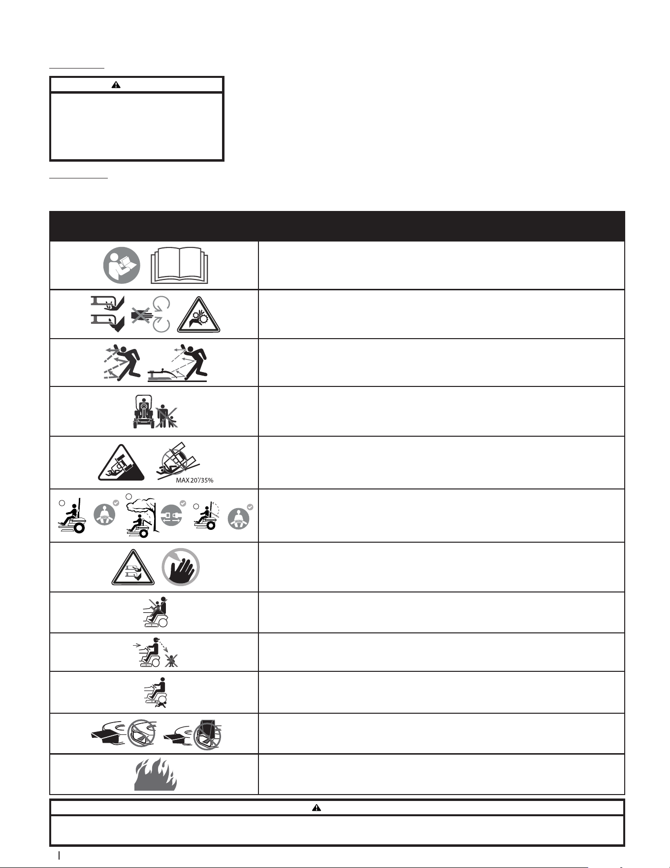
Safety Symbols
This page depicts and describes safety symbols that may appear on this product. Read, understand, and follow all instructions on the machine before
attempting to assemble and operate.
Symbol Description
READ THE OPERATOR’S MANUAL(S)
Read, understand, and follow all instructions in the manual(s) before attempting to assemble
and operate.
WARNING — ROTATING PARTS
Do not put hands or feet near rotating parts or under the cutting deck. Contact with the
blade(s) can amputate hands and feet.
WARNING — THROWN OBJECTS
This machine may pick up and throw objects which can cause serious personal injury.
BYSTANDERS
Keep bystanders, helpers, children, and pets at least 75 feet (23 meters) from the machine
while it is in operation.
WARNING — SLOPE OPERATION
Do not operate this machine on a slope greater than 20° (35%).
2
3
1
WARNING — AVOID SERIOUS INJURY OR DEATH FROM ROLLOVER
Keep roll bar in the raised upright position with your seat belt fastened. Lower roll bar and do
not fasten seat belt in low clearance situations. Raise roll bar and fasten seat belt as soon as
clearance permits.
DANGER — ROTATING BLADES
To reduce the risk of injury, keep hands and feet away. Do not operate unless discharge cover or
grass catcher is in its proper place. If damaged, replace immediately.
DANGER — CHILDREN
Never carry children, even with the blade(s) shut off. They may fall off and be seriously injured or
interfere with safe machine operation.
DANGER — MOWING IN REVERSE
Always look behind and down for small children. Use slow speed.
DANGER — BACK-OVER
To avoid back-over accidents, always disengage blades before traveling in reverse.
DANGER — SAFETY DEVICES
Keep safety devices (guards, shields, switches, etc.) in place and working.
DANGER — GASOLINE IS FLAMMABLE
Allow the engine to cool at least 5 minutes before refueling.
WARNING
Your Responsibility — Restrict the use of this power machine to persons who read, understand, and follow the warnings and instructions in this manual and on the machine.
SAVE THESE INSTRUCTIONS!
Spark Arrestor
WARNING
This machine is equipped with an internal combustion
engine and should not be used on or near any
unimproved forest-covered, brush-covered, or grass-
covered land unless the engine’s exhaust system is
equipped with a spark arrestor meeting applicable
local or state laws (if any).
If a spark arrestor is used, it should be
maintained in effective working order by
the operator. In the State of California the
above is required by law (Section 4442 of the
California Public Resources Code). Other states
may have similar laws. Federal laws apply on
federal lands.
A spark arrestor for the muffler is available
through your nearest engine authorized
service dealer or contact the service
department, P.O. Box 361131, Cleveland,
Ohio 44136-0019.
7Section 1 — Safe operation practiceS
(OK)
(TOO STEEP)
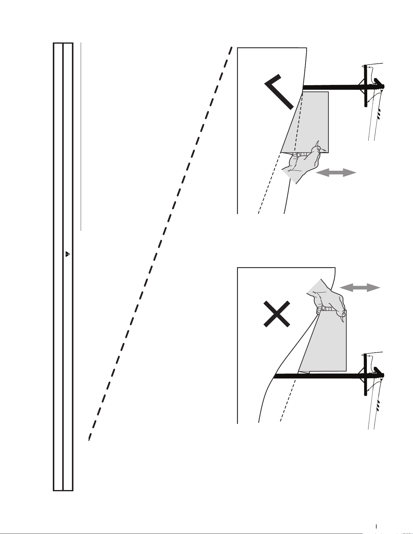
USE THIS SLOPE GAUGE TO DETERMINE
IF A SLOPE IS TOO STEEP FOR SAFE OPERATION!
To check the slope, proceed as follows:
1. Remove this page and fold along the dashed line.
2. Locate a vertical object on or behind the slope (e.g. a pole, building, fence, tree, etc.)
3. Align either side of the slope gauge with the object (See Figure 1 and Figure 2 ).
4. Adjust gauge up or down until the left corner touches the slope (See Figure 1 and Figure 2).
5. If there is a gap below the gauge, the slope is too steep for safe operation (See Figure 2 above).
20°/35% dashed line
Slope Gauge
Figure 2Figure 1
20°/35% Slope
20°/35% Slope
Use this page as a guide to determine slopes where you may not operate safely.
WARNING
Do not operate your tractor on such slopes. Do not mow on inclines with a slope in excess of 20°/35%. A tractor could overturn and cause serious injury. Mow across slopes, not up and down.
Assembly & Set-Up 2
8
Thank you for purchasing this product. It was carefully engineered to provide
excellent performance when properly operated and maintained.
Please read this entire manual prior to operating the equipment. It instructs you
how to safely and easily set up, operate and maintain your machine. Please be
sure that you, and any other persons who will operate the machine, carefully
follow the recommended safety practices at all times. Failure to do so could
result in personal injury or property damage.
All information in this manual is relative to the most recent product information
available at the time. Review this manual frequently to familiarize yourself
with the machine, its features and operation. Please be aware that this
Operator’s Manual may cover a range of product specifications for various
models. Characteristics and features discussed and/or illustrated in this
manual may not be applicable to all models. We reserve the right to change
product specifications, designs and equipment without notice and without
incurring obligation.
If applicable, the power testing information used to establish the power rating
of the engine equipped on this machine can be found at www.opei.org or the
engine manufacturer’s web site.
If you have any problems or questions concerning the machine, phone your
local authorized service dealer or contact us directly. We want to ensure your
complete satisfaction at all times.
Throughout this manual, all references to r ight and left side of the machine are
observed from the operating position.
Thank You
Contents of Carton
• Zero-Turn Mower (1) • Steering Wheel (1) • Seat Tilt Knob Assembly & Hardware Pack (1)
• Seat Mounting Hardware (1) • Battery Installation Hardware (1) • Mower Operator’s Manual (1)
• Engine Operator’s Manual (1)
Note: This Operator’s Manual covers
several models. Mower features may vary
by model. Not all features in this manual
are applicable to all mower models
and the mower depicted may differ
from yours.
Note: All references in this manual to the
left or right side and front or back of the
machine are from the operating position
only. Exceptions, if any, will be specified.
Mower Preparation
TOOLS NEEDED: Safety glasses, leather
gloves, wire cutters
1. Remove the upper crating material
from the shipping pallet, and cut
any bands or tie straps securing the
mower to the pallet.
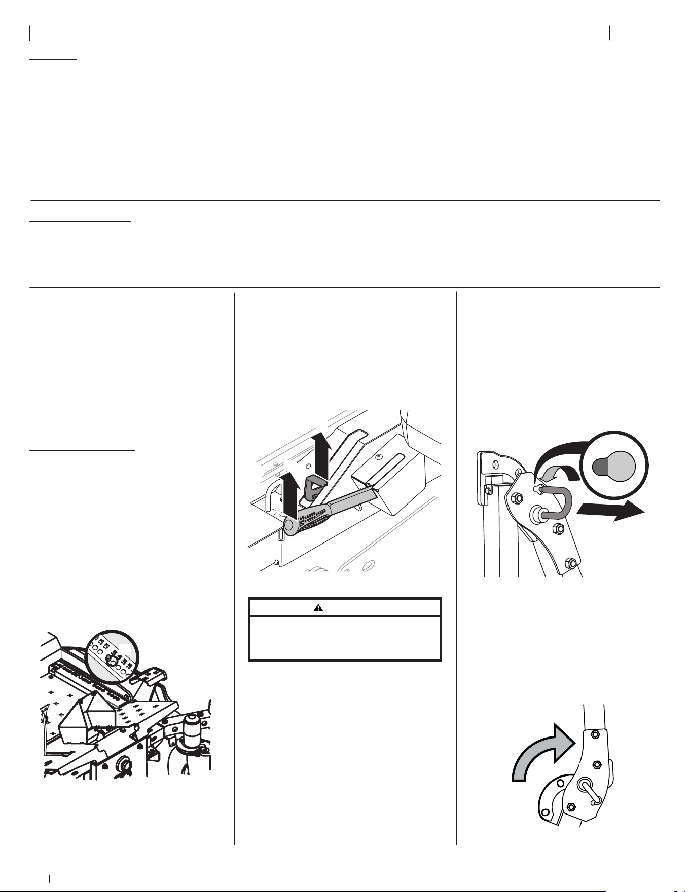
2. Use the deck lift pedal (a) to raise
the deck to its highest position
and secure in place with the clevis
pin (b) attached to the mower. See
Figure 2-1.
(a)
(b)
Figure 2-1
3. The two hydrostatic transmissions
are equipped with a bypass valve
that will allow you to manually
move the mower short distances.
4. Engage the transmission bypass
valves by pulling the bypass lever
(a) outward then upward and all the
way back. See Figure 2-2.
(a)
(b)
Figure 2-2
WARNING
Do not tow the mower, even with the bypass
valves engaged. Serious transmission damage
will result from doing so.
5. Carefully roll the mower off the
shipping pallet.
6. To release the bypass lever (a), push
the lever forward. See Figure 2-2.
7. To engage the parking brake, pull
back completely on the parking
brake lever (b). See Figure 2-2.
8. Cut any wire ties holding the
chute deflector up and discard any
packing material.
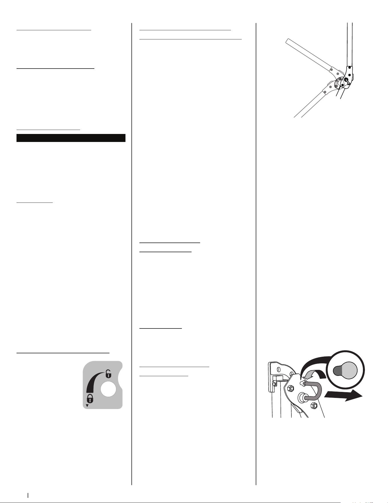
Roll Over Protective System (ROPS)
1. Pull slightly up on the upper
ROPS to relieve any tension on
the locking pin (a) and rotate the
locking pin (a) from the LOCKED (b)
position into the ADJUSTMENT (c)
position. See Figure 2-3. Repeat the
procedure for the locking pin on
the opposite side.
(c)
(b)
(a)
Figure 2-3
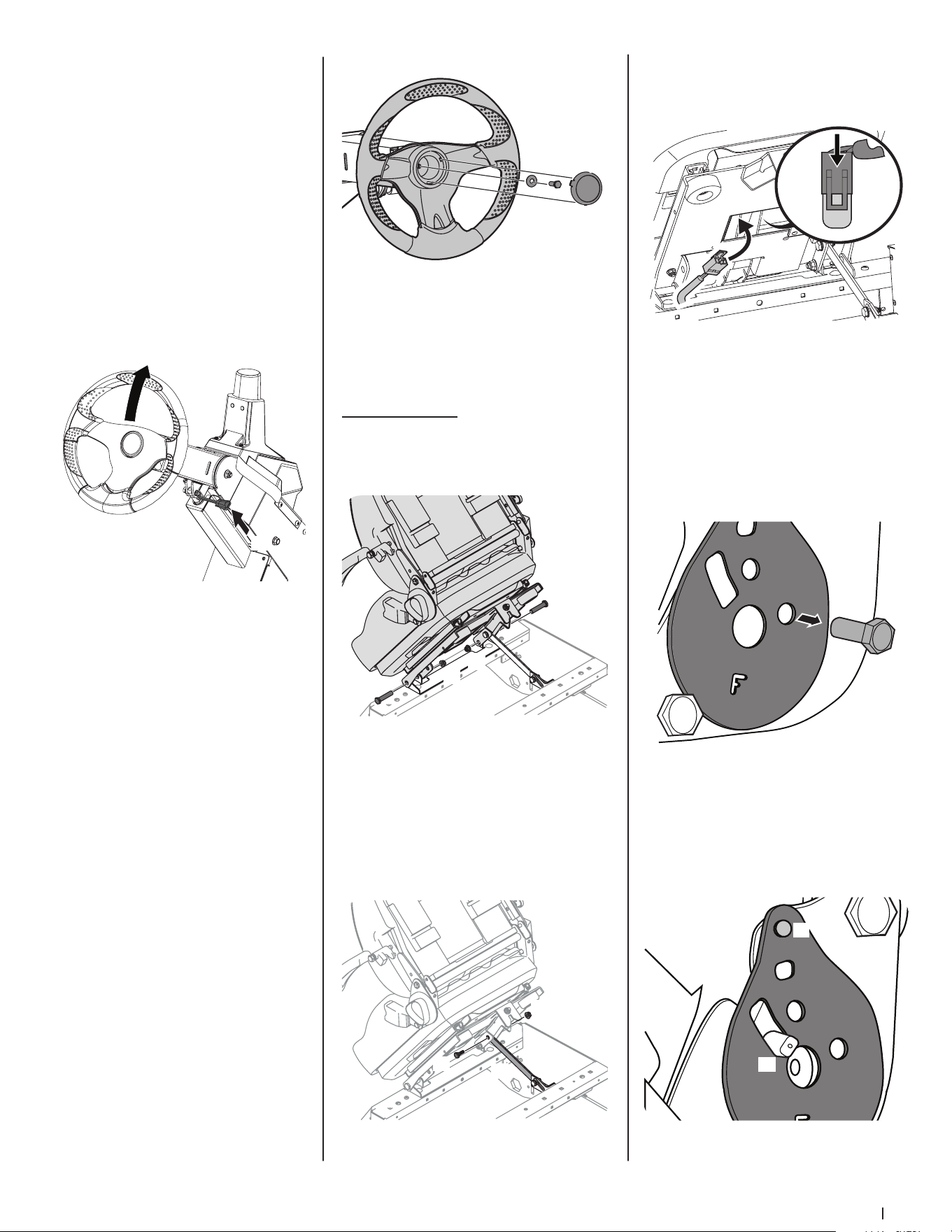
2. When both locking pins are secured
in the ADJUSTMENT position, slowly
lift and rotate the upper ROPS from
the TRANSPORT (a) position, past
the TRANSPORT WITH BAGGER (b)
position and into the OPERATION (c)
position. See Figure 2-4.
(a)
(b)
(c)
Figure 2-4
9Section 2 — ASSembly & Set-Up
3. Rotate both locking pins into the
LOCKED position. Move the upper
ROPS slightly until the locking
pins are fully engaged in the
LOCKED position.
Steering Wheel Column
The steering wheel column is tilted all
the way down for shipping purposes. To
adjust the column pull up on the steering
column adjustment lever (a) and move
the steering column up into the desired
position. Release the steering column
adjustment lever (a) to secure the
steering column in the desired position.
See Figure 2-5.
(a)
Figure 2-5
Steering Wheel
IMPORTANT! Do not use impact tools
to install or remove the steering wheel.
Doing so may cause damage to critical
power steering components.
1. Remove the hardware for attaching
the steering wheel from beneath
the steering wheel cap (a). Carefully
pry off the steering wheel cap
(a) to remove the hardware. See
Figure 2-6.
2. With the wheels of the machine
pointing straight forward, place the
steering wheel (b) over the steering
shaft. See Figure 2-6.
3. Place the Belleville washer (c) over
the steering wheel (b) and secure
with the hex lock screw (d). See
Figure 2-6.
(a)
(b)
(c)
(d)
Figure 2-6
4. Place the steering wheel cover over
the center of the steering wheel
and push downward until it “clicks”
into place.
Operator’s Seat
1. Remove the two flange lock nuts
(b) and shoulder bolts (a) from the
manual bag. See Figure 2-7.
(a)
(b)
(a)
(b)
Figure 2-7
2. Place the seat into position and
secure the seat into place with the
hardware as shown in Figure 2-7.
3. Remove the shoulder screw (a) and
flange lock nut (b) from manual bag
and install the seat lockout bracket
(c) as shown in Figure 2-8.
(c)
(a)
(b)
Figure 2-8
4. Insert the wiring harness (a) into
the bottom of the seat as shown in
Figure 2-9.
(a)
(a)
Figure 2-9
Note: When the wiring harness (a)
is connected, be sure to push the
excess wire from the wire harness
(a) into the seat box hole before
continuing. See Figure 2-9.
5. Remove the screw (a) securing
the recliner plate in the seat back
position. See Figure 2-10.
(a)
Figure 2-10
6. Tilt the seat forward into the full
forward position. Replace the
recliner plate with the clinch-stud
(a) and the recliner pin (b) passing
through the recliner plate in the
locations shown in Figure 2-11.
(b)
(a)
Figure 2-11
10 Section 2 — ASSembly & Set-Up
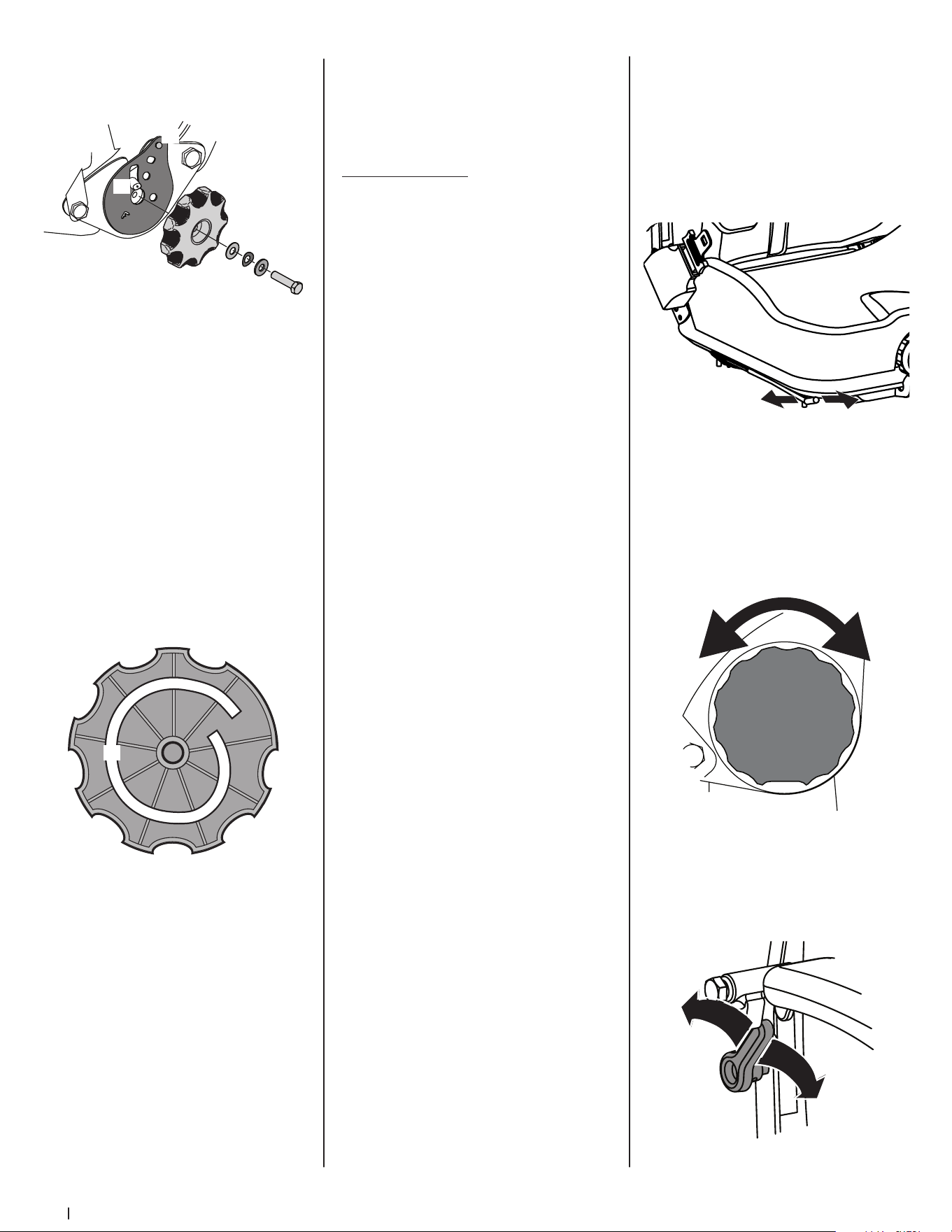
7. Remove the seat tilt knob assembly
from the bag and install as shown
in Figure 2-12.
(h)
(c)
(d)
(b)
(f)
(a)
(g)
(e)
Figure 2-12
Note: Be sure to orient the recliner
plate (a) and install the plastic
washer (b), spring washer (c) and
metal washer (d) as shown in
Figure 2-12. The plastic washer is on
the inside.
8. Slide the recliner bearing plate (a)
onto the recliner pin (e). Refer to
Figure 2-12.
9. Then align the spiral (a) on the
inside of the recliner knob with the
recliner pin. Make sure the hub on
the back of the recliner sits properly
into the large holes of the side
plate. See Figure 2-13.
(a)
Figure 2-13
10. Use a wrench to hand tighten the
hex screw (g) until the recliner
knob (f) is difficult to turn. Refer to
Figure 2-12.
Note: Do not use power tools
to install.
11. Gradually loosen the hex screw (g)
until the recliner knob moves freely.
Do not loosen the hex screw (g)
more than one full turn. Refer to
Figure 2-12.
12. Securely install the 1/4” nut onto
the clinch-stud (h) and rotate
the recliner knob to check the
operation of the seat. Refer to
Figure 2-12.
Seat Adjustment
Proper steering column and seat
adjustment will result in the following (to
adjust the seat see below):
In the neutral position with hands on the
steering wheel,
• Operator’s upper arms should be
relaxed and approximately vertical.
• Operator’s forearms should be
approximately horizontal.
• Operator’s back should stay in
contact with the seat back.
• Steering column should not contact
operator’s legs.
Check the results of any adjustments to
the conditions described above. Repeat
any adjustment procedures as required
until all conditions are met.
This machine is equipped with an
adjustable seat, which includes a
retractable seat belt assembly and an
Operator Presence Sensor (OPS). The
OPS, in the form of a switch, is integrated
into the seat bottom and is connected
to the machine electrical system. The
OPS must be connected to the electrical
wiring harness.
The seat can be adjusted forward and
backward, the armrests can be adjusted
up and down, and air ride adjustment,
a lumbar support, can be adjusted. The
seat can also tilt forward and backward.
Note: The seat base must be secured by
the latch, otherwise, the seat assembly
could tilt forward.
Seat Position
To move the seat forward or back, locate
the seat adjustment rod (a) under the
seat. Push the rod to the left, slide the
seat forward or back into the desired
position and release the rod when
the seat is in the desired position. See
Figure 2-14.
(a)
Figure 2-14
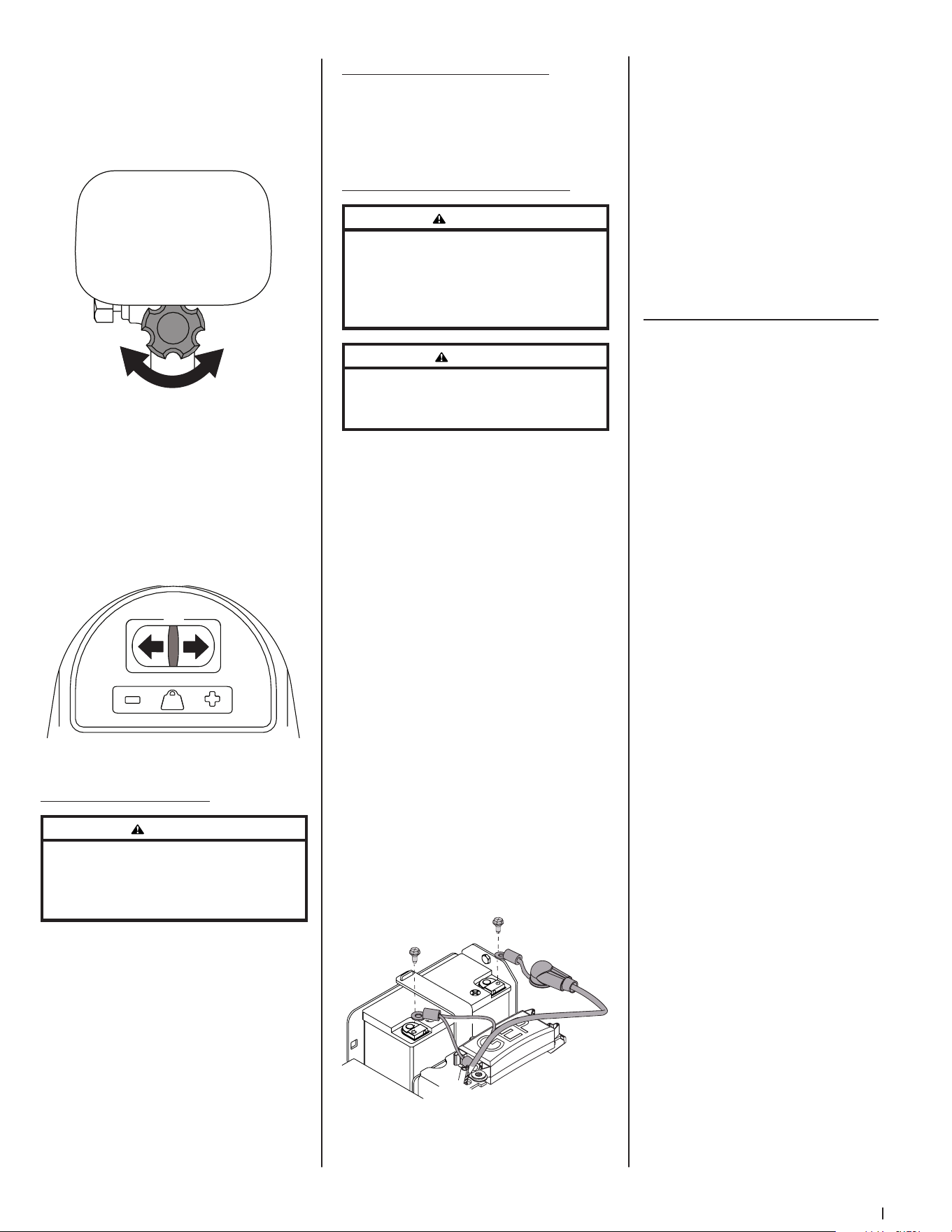
Seat Tilt
The seat tilt is controlled by the knob
on the left of the seat. Turn the knob
rearward to tilt the seat back, turn the
knob forward to tilt the seat forward. See
Figure 2-15.
Figure 2-15
Seat Lumbar
To vary the lumbar support move the
lever on the right of the seat up and
down. See Figure 2-16.
Figure 2-16
11Section 2 — ASSembly & Set-Up
Seat Armrest
To adjust the height of the arm rests, lift
the arm rest and rotate the knob under
the arm rest right or left to increase or
decrease the height. See Figure 2-17.
Figure 2-17
Seat Air Ride
The air ride can be adjusted up or down
using the height adjustment lever (a) on
the front of the seat. Press the lever to
the left (+) to raise the height of seat and
to the right (-) to lower the height of the
seat. See Figure 2-18.
(a)
Figure 2-18
Checking Tire Pressure
WARNING
Maximum tire pressure under any circumstances
is 12 psi on rear tires and 25 psi on front tires.
Equal tire pressure should be maintained at
all times.
Inflation Pressure
Rear Tires — 10-12 psi max
Front Tires — 20-25 psi max
The tires on your mower may be over-
inflated for shipping purposes. Reduce
the tire pressure before operating the
mower. Recommended operating tire
pressure is 10-12 psi on rear tires and 20-
25 psi on front tires.
Lubrication & Grease Points
Before operating the mower, refer to the
Product Care section of this manual to
check the lubrication and grease points.
Grease and lubricate if necessary.
Connecting the Battery Cables
WARNING
California PROPOSITION 65: Battery
posts, terminals, and related accessories contain
lead and lead compounds, chemicals known
to the State of California to cause cancer and
reproductive harm. Wash hands after handling.
CAUTION
When attaching battery cables, always connect
the POSITIVE (Red) wire to its terminal first,
followed by the NEGATIVE (Black) wire.
For shipping reasons, both battery cables
on your equipment may have been left
disconnected from the terminals at the
factory. To connect the battery cables,
proceed as follows:
1. Using the lever on either side of the
back of the seat, lift up on the lever
and tilt the seat forward locking it
in place with the seat prop. Remove
the bolts and hex nuts from the
manual bag.
Note: The positive battery terminal
is marked POS. (+) (a). The negative
battery terminal is marked NEG. (–)
(b). See Figure 2-19.
Note: If the positive battery cable
(c) is already attached, skip ahead
to Step 4.
2. Slide the red boot (d) from the
positive battery terminal (a) and
attach the red cable (c), with
the vertical mount bolt (e). See
Figure 2-19.
(d)
(a)
(b)(b)
(c)
(e)
(e)(e)
(f)
Figure 2-19
3. Position the red boot (d) over
the positive battery terminal (a)
to insulate it and help protect it
from corrosion.
4. Attach the black cable (f), to the
negative battery terminal (b) with
the vertical mount bolt (e). See
Figure 2-19.
Note: If the battery is put into
service after the date shown on top/
side of battery, charge the battery
prior to operating the machine.
Connecting to the GPS Network
See the Controls & Operation section
for instructions on connecting to the
GPS Network.
Controls & Operation
3
12
† — If equipped
2
7
†
21
†
8
29
29
25
11 11
28
†
28
†
24
23
10
9
30
20
†
19
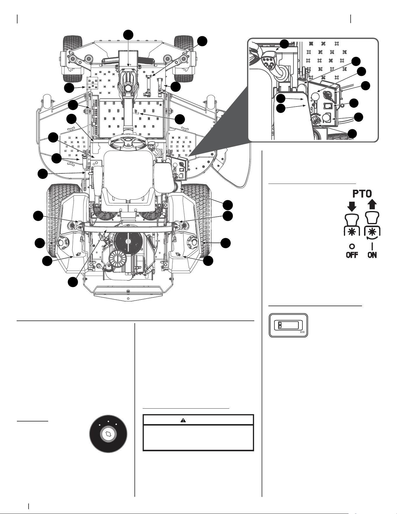
Figure 3-1
NOTE: All references in this manual to
the left or right side and front or back
of the machine are from the operating
position only. Exceptions, if any, will
be specified.
NOTE: This Operator’s Manual covers
several models. Mower features may vary
by model. Not all features in this manual
are applicable to all mower models
and the mower depicted may differ
from yours.
1. Ignition
The ignition switch
is located on the RH
console to the rear of
the throttle control.
The ignition switch has three positions
as follows:
OFF — The engine and electrical system
are turned off.
O
F
F
O
N
S
T
A
R
T
ON — The mower electrical system
is energized.
START — The starter motor will turn over
the engine. Release the key immediately
when the engine starts.
NOTE: To prevent accidental starting
and/or battery discharge, remove the
key from the ignition switch when the
mower is not in use.
2. Transmission Bypass Lever
WARNING
Do not tow the mower, even with the bypass valves
engaged. Serious transmission damage will result
from doing so.
The transmission bypass lever is located
next to the LH console to the left of the
operator’s seat.
When engaged the valves open a bypass
within the hydrostatic transmissions.
Refer to the Assembly & Set-Up
section for instructions on using the
bypass feature.
3. Power Take-Off (PTO) Knob
The PTO knob is located
on the RH console
to the right of the
operator’s seat.
The PTO knob operates
the electric PTO clutch
mounted on the bottom
of the engine crankshaft.
Pull the knob upward to
engage the PTO clutch, or push the knob
downward to disengage the clutch.
The PTO knob must be in the OFF
position when starting the engine.
4. Hour Meter & Service Minder
0.0
The hour meter and
service minder is located
on the RH console to the
right of the operator’s
seat. It records the hours that the mower
has been operated, engine speed (RPM)
and service reminders (oil, lube) in the
digital display.
The hour meter and service minder is
activated whenever the ignition switch
is turned to the ON position. Keep a
record of the actual hours of operation
to assure all maintenance procedures are
completed according to the instructions
in this Operator’s Manual and the Engine
Operator’s Manual. The hour meter
and service minder is equipped with a
MODE button that can toggle between
available functions and can be used to
reset service alerts. Press and hold the
MODE button for three (3) seconds while
in service alert mode or when in a service
alarm mode to reset.
1
3
4
5
†
6
28
†
31
26
27
†
13Section 3 — controlS & operation
NOTE: When the ignition key is out
of the STOP position the hourglass
symbol is illuminated/blinks to indicate
it is recording the hours of mower
operation, regardless of whether the
engine is started.
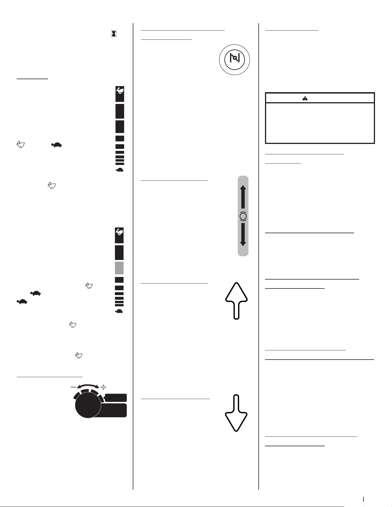
5. Throttle
Manual Throttle (If equipped)
The throttle control is located on
the RH console to the right of the
operator’s seat. When set in a given
position, a uniform engine speed
will be maintained. The throttle
control moves between the FAST
and slow positions.
Push the throttle control handle
forward to increase the engine
speed. The mower is designed to
operate with the throttle control
in the FAST (full throttle) position
when the mower is being driven and the
mower deck is engaged.
Pull the throttle control handle rearward
to decrease the engine speed.
Electronic Throttle (E-Governor)
Lever (If equipped)
The electronic throttle
(E-governor) lever is used to
control engine speed and RPM’s. It
also helps control fuel efficiency.
The electronic throttle lever
moves between the FAST and
slow positions. The SLOW
position is used for basic
transportation of the mower with
the PTO disengaged and uses the
least fuel. The FAST position should
be used when the PTO is engaged and
uses the most fuel. The mower should be
started in the START position, but should
always be in the FAST position when
the PTO/deck is being used.
6. Cutting Width Knob
The cutting width
knob, only available
when mower is in
SurePath Auto Steer
Mode, is located
on the RH console to the right of the
operator’s seat and has four positions.
MOST EFFICIENT is suitable for most
terrains and maintains standard mowing
path overlap. Turn dial progressively
from right to left if operating under
extreme conditions or if visible sections
of uncut grass occur when mower is in
MOST EFFICIENT setting.
F A S T
SLOW
F A S T
SLOW
START
MOST
EFFICIENT
C
utting
W
idth
7. Choke Knob (If equipped)/
MIL (If equipped)
Choke Knob (If
equipped) - The choke
knob is located on the left
side of the mower next to
the operator’s seat. Pull
the knob out to choke the engine; push
the knob in/down to open the choke.
Having the choke in the ON position
helps the engine to start during initial
start-up. During normal operation the
choke should be OFF.
MIL (If equipped) - The Multifunction
Indicator Light (MIL) provides diagnostic
information for the engine. If the MIL
lights up and/or flashes see the service
manual or contact your service center.
8. Parking Brake Lever
The parking brake lever is located
to the left of the operator’s seat.
When pulled up it engages the
parking brake and when pushed
down it releases the brake.
NOTE: If the forward or reverse
drive pedal is engaged when
engaging the parking brake, the
engine will stop. The parking brake
must be placed in the engaged
position when starting the engine.
9. Forward Drive Pedal
The forward drive pedal is
located on the right side of
the machine, directly to the
right of the steering column
and along the running board.
Press the forward drive pedal forward
to cause the mower to travel forward.
Ground speed is also controlled with the
forward drive pedal. The further forward
the pedal is pivoted, the faster the
mower will travel. The pedal will return
to its original/neutral position when it’s
not pressed.
10. Reverse Drive Pedal
The reverse drive pedal is
located on the right side of
the mower, to the right of the
forward drive pedal, along the
running board. Ground speed
is also controlled with the reverse drive
pedal. The further downward the pedal is
pivoted, the faster the mower will travel.
The pedal will return to its original/
neutral position when it’s not pressed.
CHOKE
ON
OFF
P
11. Fuel Tank Caps
The fuel tank caps are located on the
top of the fuel tank on the left and right
side of the seat. Turn the fill cap counter-
clockwise to remove and clockwise until
it clicks three times to tighten. Always
re-install the fuel cap tightly onto the
fuel tank after removing.
WARNING
Never fill the fuel tank when the engine is running.
If the engine is hot from recently running, allow to
cool for several minutes before refueling. Highly
flammable gasoline could splash onto the engine
and cause a fire.
12. Seat Adjustment Lever
(Not shown)
The seat adjustment lever is located
below the front/right of the seat. The
lever allows for adjustment forward or
rearward of the operator’s seat. Refer
to the Assembly & Set-Up section
for instructions on adjusting the
seat position.
13. Seat Tilt Knob (Not shown)
The seat tilt knob is located on the left
side of the seat. Refer to the Assembly
& Set-Up section for instructions on
adjusting the seat tilt.
14. Arm Rest Height Knobs (Not
shown, if equipped)
The arm height knobs are located
under the seat arms and can be used
to adjust the height of the arm rests.
Refer to the Assembly & Set-Up section
for instructions on adjusting the arm
rest position.
15. Mechanical Suspension
Mechanism (Not shown, if equipped)
The mechanical suspension mechanism
is located on the front of the seat
and can adjust the weight/ride
adjustment for operators in the 125- to
275-pound weight range. Refer to
the Assembly & Set-Up section for
instructions on adjusting the mechanical
suspension mechanism.
16. Lumbar Support Lever (Not
shown, if equipped)
The lumbar support lever is located on
the right side of the seat on the seat
back. Refer to the Assembly & Set-Up
section for instructions on adjusting the
lumbar support.
14 Section 3 — controlS & operation
17. Seat Prop (Not shown)
The seat prop is located on the left, rear
side of the operator’s seat. It is used to
prop the seat forward.
18. Seat Latch (Not shown)
The seat latch is located below the
rear, center of the operator’s seat. The
latch is used to secure the seat into the
operating position. Lift the latch and tilt
the seat forward to access the area under
the seat.
19. Deck Height Index
4.50
"
3.
5
0"
2.50"
1.
5
0"
4.75"
3.75"
2.75
"
1.75"
5
"
4
"
3"
2"
1"
3.25"
4.
25
"
2.25
"
1.2
5
"
The deck height index consists of several
holes located on the left of the foot
platform. Each hole corresponds to a
1/4” change in the deck height position
ranging from 1” at the lowest notch to 5”
at the highest notch.
20. Deck Lift
Deck Lift Pedal (If equipped)
The deck lift pedal is located on the
left front corner of the foot platform,
and is used to raise and lower the
mowing deck.
To raise the mowing deck to the
transport position, push the pedal
all the way forward until the deck
transportation lock snaps into position.
To remove the deck from the transport
position push forward on the deck lift
pedal and pull up on the deck lock rod.
To position the deck push the pedal all
the way forward, remove the clevis pin,
reinsert it in the desired cutting height
and slowly release pressure on the pedal
until you reach the clevis pin.
21. Transport Lock (If equipped)
The transport lock is
located on the left
side of the operator’s
seat and is used to
lock the deck in the
transport position.
Press down on the
deck lift pedal and
lift up on the deck lift
release lever to release the deck.
TRANSPORT FLOAT
LOCK TRANSPORT
22. Transmission Oil Expansion
Reservoir (Not shown, if equipped)
The 900 series is equipped with a
transmission oil expansion reservoir
located under the seat, connected by
hoses to the RH and LH transmission
assemblies. The function of the reservoir
is to hold the natural expansion of
transmission oil that occurs as the
transmission warms up during operation.
DO NOT FILL THE RESERVOIR.
Under normal operating conditions, no
oil should be added to the reservoir. The
COLD oil level should be approximately
1/4” above the bottom of the reservoir
on 900 models. See the Product
Care section of this manual for more
information on the transmission oil
expansion reservoirs.
NOTE: Prior to the initial operation of the
mower, the oil level in the reservoir may
be slightly higher than the maximum
due to air in the oil lines. Operation of
the mower will eventually purge the air
from the lines and the oil level will settle
to the maximum.
23. Steering Column
Adjustment Lever
The steering column adjustment lever is
located on the right side of the steering
column. To adjust the column pull up on
the steering column adjustment lever
and move the steering column up into
the desired position. Release the steering
column adjustment lever to secure the
steering column in the desired position.
24. Cup Holder
The cup holder is located between the
fuel tank and the control panel to the
right of the seat.
25. Roll Over Protective
Structure (ROPS)
ROPS Positions
Refer to Figure 3-2 and the following
descriptions and uses for the three (3)
positions for the ROPS.
Transport Position
Transport with
Bagger Position
Operation Position
Figure 3-2
• TRANSPORT: Only to be used
when transporting the mower or
when they need to be momentarily
folded-down to avoid contact with
items such as tree limbs, clothes
lines, guy wires, utility poles,
buildings, etc.
• TRANSPORT WITH BAGGER:
Allows for the ROPS to be lowered
for situations outlined for the
TRANSPORT position when the
mower is equipped with a bagger.
• OPERATION: The ROPS should
always be in this position when
operating unless the situations
involved outlined in the
TRANSPORT and TRANSPORT WITH
BAGGER descriptions arise.
1. To change the position of the ROPS,
pull slightly up/push forward on the
upper ROPS to relieve any tension
on the locking pin (a) and rotate the
locking pin (a) from the LOCKED
(b) position into the ADJUSTMENT
(c) position. Repeat the procedure
for the locking pin on the opposite
side. See Figure 3-3.
(c)
(b)
(a)
Figure 3-3
2. Move the ROPS into the desired
position. The three positions are
TRANSPORT position, TRANSPORT
WITH BAGGER position and into
the OPERATION position. See
Figure 3-2.
15Section 3 — controlS & operation
The GPM includes:
• Light Module (Indicator/Warning
Lights) - the Indicator/Warning
Lights are mounted on the back
(facing the operator) of the GPM
and visually communicate the
status of the SurePath Auto Steer
system to the operator. The two
lights will always match in color and
operation (flashing or solid).
• 4G Modem Antenna - integrated
antenna for the 4G Modem.
• On-Board Computer - the GPM
houses the main microprocessors,
software and logic to provide
guidance to the equipment’s
drive systems.
See Service in the Product Care section
for information on servicing the GPM.
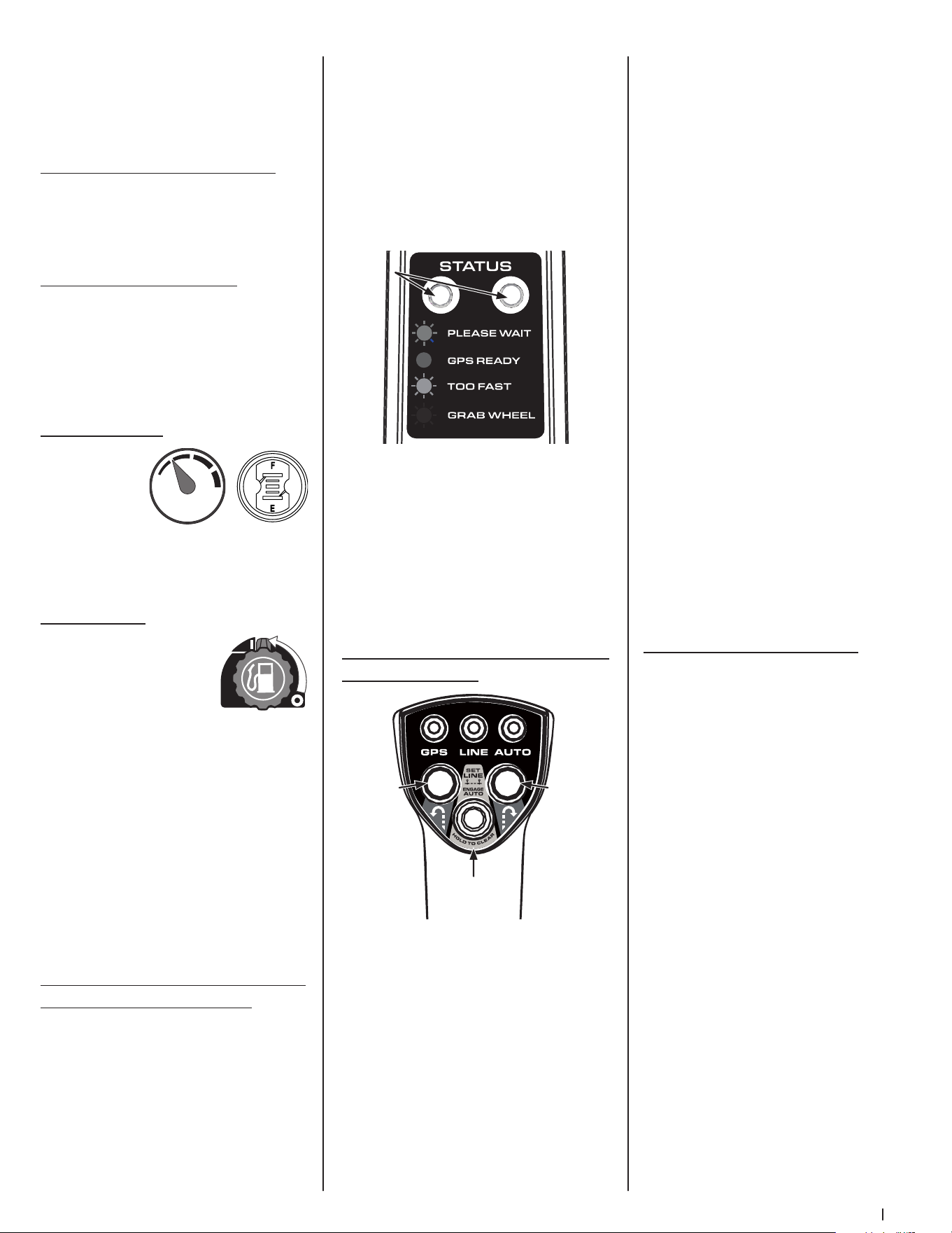
31. Operator Control Panel (SurePath
Auto Steer System)
GPS — Green indicators will flash on the
Light Module and Operator Control Panel
GPS indicator while the GPM is actively
searching for a signal and will turn solid
green when signal is acquired.
LINE — Initially the LINE indicator will be
off. The LINE indicator will flash green
when first point (A) has been set and will
turn solid green once second point (B)
has been set.
IMPORTANT! Operator should drive a
minimum of 10 yards (30 feet) between
setting point A and point B.
Blue
Green
Yellow
Red
Indicator Indicator
Lights
Lights
Set Line/
Engage Auto
Button
Left
Turn
Button
Right
Turn
Button
3. Rotate both locking pins into the
LOCKED position. Move the upper
ROPS slightly until the locking
pins are fully engaged in the
LOCKED position.
26. Accessory Switch Receptacles
The two receptacles for optional
accessories are on the RH console. See
the Attachments & Accessories section
for information.
27. 12V Outlet (If equipped)
The 12V outlet is located to the right of
the operator’s seat on the lower panel of
the RH console and is used for the
convenience of plugging in accessories
that require a power source with a
maximum load of 5A at 12V.
28. Fuel Gauge(s)
There is a fuel
gauge on top
of each of the
two fuel tanks
or a single
gauge to the right of the operator’s seat
on the RH console. The gauges measure
the fuel level in each tank.
29. Fuel Valves
The fuel valves are located
near the rear of each fuel
tank. The valves control
the fuel flow from the
right and left tank and
also can shut off fuel flow to the engine.
Rotate the valve counter-clockwise to
open the flow from the tank(s). Rotate
the valve clockwise to stop the flow
from the tank(s). The fuel tanks can be
operated together, independently or
shut the fuel flow off completely.
NOTE: If both tanks are on, and one
is empty, the engine will not start. Be
certain to make sure both tanks have
fuel or that the empty tank’s fuel valve
is closed.
30. Global Positioning Module (GPM)
(SurePath Auto Steer System)
The Global Positioning Module (GPM),
mounted to the front of the steering
wheel column, is the main component of
the SurePath Auto Steer system.
AUTO — The AUTO indicator will be
solid green when mower is in auto mode
and will flash slowly when mower is in
manual mode with auto mode available
(points A and B have been set and GPS
signal is good). The AUTO indicator is
off when the mower is not ready for
auto mode.
NOTE: Auto indicator will only flash after
overriding auto mode by turning the
steering wheel slightly to the right or left
or if the system loses GPS signal. Points A
and B remain set.
LEFT TURN BUTTON — Mower will
perform an automated zero turn to the
left while in SurePath Auto Steer Mode.
RIGHT TURN BUTTON — Mower will
perform an automated zero turn to the
right while in SurePath Auto Steer Mode.
SET LINE/ENGAGE AUTO BUTTON — Sets
beginning (A) and ending (B) points for
automatic mowing. This button is also
used to resume auto mode (press once
after system is disengaged).
NOTE: SET LINE/ENGAGE AUTO button
also serves as the reset button to clear
the set line. See Clearing the Mowing
Line (SurePath Auto Steer Mode) later in
this section for more information.
Before Operating Your Mower
1. Before you operate the mower,
study this manual carefully to
familiarize yourself with the
operation of all the instruments and
controls. It has been prepared to
help you operate and maintain your
machine efficiently.
2. Fill the fuel tank with only clean,
fresh, unleaded gasoline with a
pump sticker octane rating of 87 or
higher. When the fuel reaches 1/2”
below the bottom of the fill neck,
stop. DO NOT OVERFILL. Space
must be left for expansion.
3. Never use gasoline containing more
than 10% ethanol or methanol.
4. Check the engine oil level
as instructed in the Engine
Operator’s Manual.
16 Section 3 — controlS & operation
5. Check the transmission oil level. The
transmission oil expansion reservoir
is located beneath the operator’s
seat. Always wipe off the area
around the reservoir fill neck before
checking the oil level to prevent dirt
from contaminating the oil. Remove
the cap and make sure the oil level
is 1/4” above the bottom of the
reservoir. If the oil level is low, fill
with Castrol™ (Syntec®) Edge™.
6. Check the tire inflation pressures.
10-12 psi for the rear tires, 20-25 psi
for the front tires.
NOTE: New tires are over-inflated in
order to properly seat the bead to
the rim.
7. Check that all nuts, bolts and screws
are tight.
8. Check the tension of the deck
drive belts.
a. Remove the deck cover.
b. The tension of the deck
drive belts are maintained
by a spring mechanism that
adjusts for wear and stretch.
c. Examine the belts for cuts,
fraying and excessive wear.
Replace if any of these
are detected.
d. Replace the deck cover.
9. Check if deck is level. When
correctly adjusted the mower
deck should be level side to side,
and the front of the deck should
be approximately 1/4” lower than
the rear of deck. If deck needs to
be leveled, refer to the Product
Care section.
10. Lubricate all pivot points listed in
the Product Care section.
11. Adjust the seat for operator’s
maximum comfort, visibility and
for maintaining complete control of
the machine. Refer to the Assembly
& Set-Up section for instructions on
adjusting the seat.
Safety Interlock System
This machine is equipped with a safety
interlock system for the protection of
the operator. If the interlock system
should ever malfunction, do not operate
the machine. Contact your authorized
service dealer.
• The safety interlock system
prevents the engine from cranking
or starting unless the speed control
pedals are in the neutral position,
the parking brake is engaged and
the PTO knob is disengaged.
• To avoid sudden movement when
disengaging the parking brake, the
safety interlock system will shut
off the engine if the speed control
pedals are moved to a position
other than the neutral position
when the parking brake is engaged.
• The safety interlock system will
shut off the engine if the operator
leaves the seat before engaging the
parking brake.
• The safety interlock system will
shut off the engine if the operator
leaves the seat with the PTO knob
engaged, regardless of whether the
parking brake is engaged.
NOTE: The PTO knob must be in
the disengaged position to restart
the engine.
Practice Operation (Initial use)
Operating a zero-turn mower is not
like operating a conventional type
riding mower. Although and because a
zero-turn mower is more maneuverable,
getting used to operating the speed
control pedals and the steering wheel
takes some practice.
It is strongly recommended that you
locate a reasonably large, level and
open “practice area” where there are no
obstructions, pedestrians or animals. You
should practice operating the mower for
a minimum of 30 minutes.
Carefully move (or have moved) the
mower to the practice area. When
performing the practice session, the
PTO knob should not be engaged.
While practicing, operate the mower
at approximately 1/2-3/4 throttle and
at less than full speed in both forward
and reverse.
Always wear appropriate clothing
and personal protection equipment
(e.g. safety glasses, long pants, gloves,
hearing protection, safety shoes, hard
hat) when operating or maintaining this
machine. Follow all federal, state and
local guidelines regarding the use of
personal protective equipment.
WARNING
Hearing protection is required for all operator
exposure exceeding two (2) hours.
Carefully practice maneuvering the
machine using the instructions in the
Driving the Mower section. Practice until
you are confident that you can safely
operate the mower.
Starting the Engine
For throttle/choke or throttle/automatic
EFI engines proceed below, for electronic
throttle/EFI engines, skip ahead to the
Electronic Throttle/EFI (Electronic Fuel
Injection) Engines section.
Manual Throttle/Choke or Throttle/
Automatic EFI (Electronic Fuel
Injection) Engines
WARNING
This machine is equipped with a safety interlock
system designed for protection of the operator.
Do not operate the machine if any part of the
interlock system is malfunctioning. Periodically
check the functions of the interlock system for
proper operation.
WARNING
For personal safety, the operator must be sitting in
the mower seat when starting the engine.
1. Open the fuel valve(s).
NOTE: If both tanks are on, and one
is empty, the engine will not start.
Be certain to make sure both tanks
have fuel or that the empty tank’s
fuel valve is closed.
2. Operator must be sitting in the
mower seat with both drive control
pedals in the neutral/start position.
3. Engage the parking brake.
4. Make certain the PTO is in the
disengaged (down) position.
5. Lift the choke knob (if equipped)
into the ON position.
NOTE: If the engine is warmed up,
it may not be necessary to choke
the engine.
NOTE: Some mowers are equipped
with EFI (Electronic Fuel Injection)
engines and are not equipped with
a choke.
6. Move the throttle control to
midway between the SLOW
and FAST positions.
17Section 3 — controlS & operation
7. Turn the ignition key clockwise
to the START position and release
it as soon as the engine starts;
however, do not crank the engine
continuously for more than 10
seconds at a time. If the engine
does not start within this time, turn
the key to OFF and wait at least
30 seconds to allow the engine’s
starter motor to cool. Try again after
waiting. If after a few attempts the
engine fails to start, do not keep
trying to start it with the choke
closed as this will cause flooding
and make starting more difficult.
8. Once the engine starts, push the
choke (if equipped) halfway down
and as the engine warms, push
the choke (if equipped) all the
way down.
Electronic Throttle (E-Governor)/EFI
(Electronic Fuel Injection) Engines
1. Open the fuel valve(s).
NOTE: To prime a dry fuel system,
turn the ignition switch to the ON
position for one minute. Allow the
fuel pump to cycle and prime the
system. Turn the ignition switch to
the OFF position.
NOTE: If both tanks are on, and one
is empty, the engine will not start.
Be certain to make sure both tanks
have fuel or that the empty tank’s
fuel valve is closed.
2. Operator must be sitting in the
mower seat with both drive control
pedals in the neutral/start position.
3. Engage the parking brake.
4. Make certain the PTO is in the
disengaged (down) position.
5. Place the Electronic Throttle lever in
the START position.
6. Turn the ignition key clockwise
to the START position and release
it as soon as the engine starts;
however, do not crank the engine
continuously for more than 10
seconds at a time. If the engine
does not start within this time, turn
the key to OFF and wait at least
60 seconds to allow the engine’s
starter motor to cool. Try again
after waiting.
NOTE: Failure to follow these
guidelines can burn out the
starter motor.
NOTE: Upon start-up, a metallic
ticking may occur. Run engine for 5
minutes. If the noise continues, run
the engine at the starting position
for 20 minutes. If the noise persists,
take the mower to your authorized
service dealer.
Cold Weather Starting
When starting the engine at
temperatures near or below freezing,
ensure the correct viscosity motor oil
is used in the engine and the battery is
fully charged. Start the engine as follows:
1. Be sure the battery is in good
condition. A warm battery has
much more starting capacity than a
cold battery.
2. Use fresh winter grade fuel. Winter
grade gasoline has higher volatility
to improve starting. Do not use
gasoline left over from summer.
3. Follow the previous instruction for
Starting the Engine.
Using Jumper Cables to Start Engine
WARNING
Batteries contain sulfuric acid and produce
explosive gases. Make certain the area is well
ventilated, wear gloves and eye protection, and
avoid sparks or flames near the battery.
If the battery charge is not sufficient to
crank the engine, recharge the battery.
If a battery charger is unavailable and
the mower must be started, the aid of
a booster battery will be necessary.
Connect the booster battery as follows:
1. Connect the end of one cable to the
disabled mower battery’s positive
terminal; then connect the other
end of that cable to the booster
battery’s positive terminal.
2. Connect one end of the other cable
to the booster battery’s negative
terminal; then connect the other
end of that cable to the frame of
the disabled mower, as far from the
battery as possible.
3. Start the disabled mower following
the normal starting instructions
previously provided; then
disconnect the jumper cables
in the exact reverse order of
their connection.
4. Have the mower’s electrical system
checked and repaired as soon as
possible to eliminate the need for
jump starting.
Stopping the Engine
1. Place the PTO switch in the
disengaged position.
2. Engage the parking brake.
3. Move the throttle to the SLOW
position and allow the engine to
idle for about one minute.
4. Turn the ignition key to the OFF
position and remove the key from
the ignition switch.
NOTE: Always remove the key
from the ignition switch to prevent
accidental starting or battery
discharge if the equipment is
left unattended.
5. Close the fuel shut-off valve(s).
Driving the Mower
1. Ensure that the area is free
of animals and bystanders,
especially children.
2. Survey the area where the
equipment is to be used to make
sure it is free of debris, sticks,
stones, wires, bones and other
foreign objects which could cause
injury to bystanders, damage
to the machine or damage to
nearby facilities.
WARNING
Avoid sudden starts, excessive speed, and
sudden stops.
3. Adjust the operator’s seat to the
most comfortable position that
allows you to operate the controls.
Refer to the Assembly & Set-Up
section for instructions on adjusting
the seat.
4. Adjust the steering wheel
tilt with the steering column
adjustment lever.
5. Release the parking brake.
6. Move the throttle control lever (if
equipped) forward to the FAST
position.
NOTE: The mower’s engine is
designed to run at full throttle, but
when performing a practice session
the mower must be operated at less
than full throttle. This only applies
to practice.
WARNING
Always maintain a firm grip on the steering wheel.
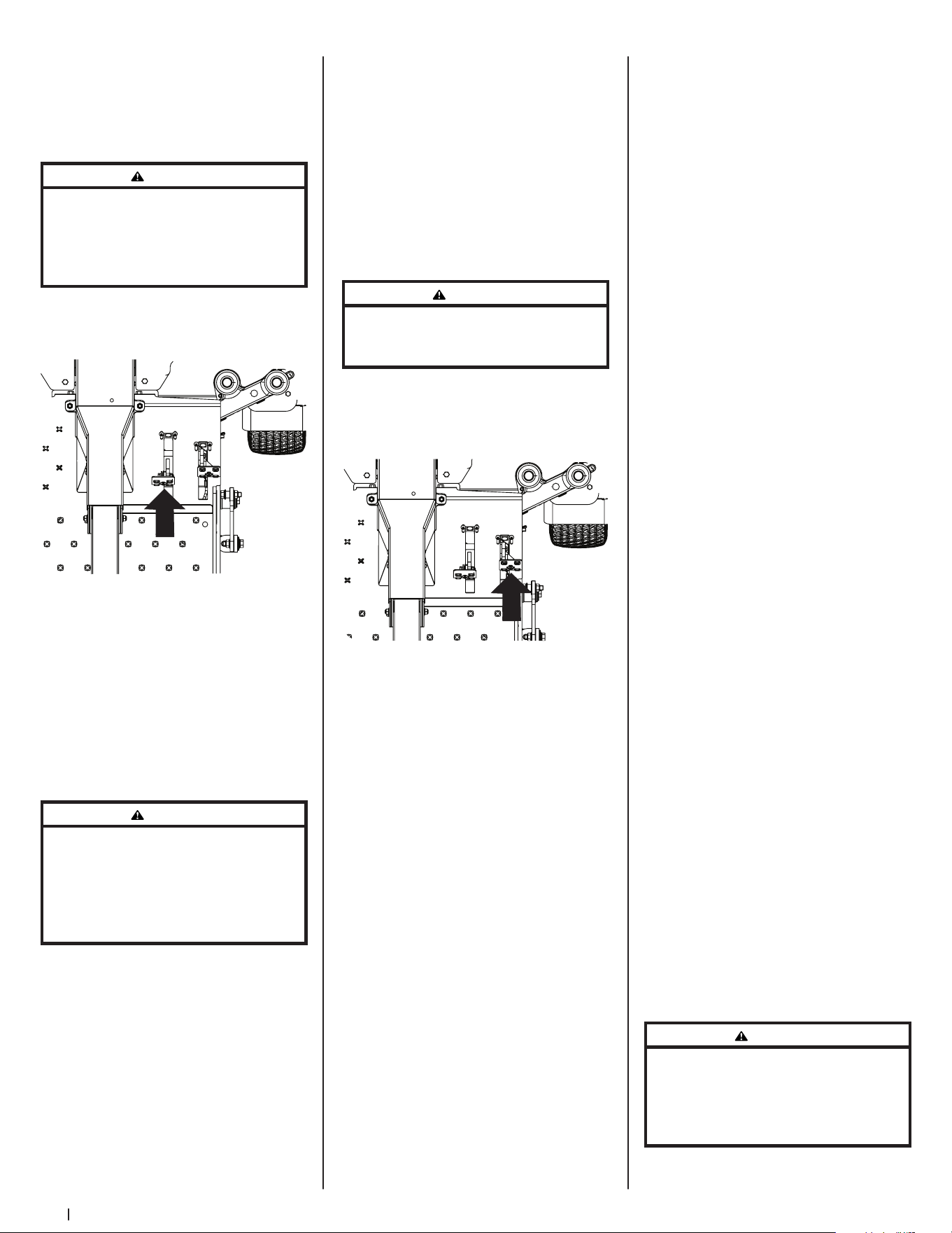
18 Section 3 — controlS & operation
7. To drive the mower, firmly grasp
the steering wheel with your right
and left hands and continue with
Driving the Mower Forward.
Driving the Mower Forward
WARNING
Keep all movement of the drive pedals slow and
smooth. Abrupt movement of the pedals can affect
the stability of the mower and could cause the
mower to flip over, which may result in serious
injury or death to the operator.
1. Slowly push the forward drive pedal
forward. The mower will start to
move forward. See Figure 3-4.
Figure 3-4
2. As the forward drive pedal is
pushed farther forward the speed
of the mower will increase.
3. To slow the mower, slowly release
the forward drive pedal to attain
the desired speed, or allow to pedal
to return to the neutral position to
stop the mower.
Turning the Mower While Driving Forward
WARNING
When reversing the direction of travel, performing
gradual “U” turns where possible is recommended.
Sharper turns increase the possibility of turf
defacement, and could affect control of the
mower. ALWAYS slow the mower before making
sharp turns.
To turn the mower while driving forward,
use the steering wheel to turn in the
direction you wish to travel.
1. To turn to the left, turn the steering
wheel counter-clockwise (to the
operator’s left).
2. To turn to the right, turn the
steering wheel clockwise (to the
operator’s right).
3. The greater the distance the
steering wheel is turned, the
sharper the mower will turn.
4. To execute a “pivot turn,” move the
steering wheel so that the inside
wheel is angled at approximately
88° and the turn side tire will
not rotate.
NOTE: Making a “pivot turn” on
grass will greatly increase the
potential for defacement of the turf
as well as potential damages to the
traction surface and the tire.
Driving the Mower in Reverse
WARNING
Always look behind and down on both sides of the
mower before backing up. Always look behind
while traveling in the reverse direction.
1. Slowly push the reverse drive pedal
forward. The mower will start to
move in the reverse direction. See
Figure 3-5.
Figure 3-5
2. As the reverse drive pedal is pushed
farther forward the speed of the
mower will increase.
3. To slow the mower release the
reverse drive pedal to attain the
desired speed, or allow the pedal
to return to the neutral position to
stop the mower.
Turning While Driving Rearward
To turn the mower while driving
rearward, use the steering wheel to turn
in the direction you wish to travel.
1. To turn to the left while traveling
in reverse, turn the steering wheel
clockwise (to the operator’s right).
2. To turn to the right while traveling
in reverse, turn the steering
wheel counter-clockwise.
3. The greater the distance the
steering wheel is turned, the
sharper the mower will turn.
4. To execute a “pivot turn,” move the
steering wheel so that the inside
wheel is angled at approximately
88° and the turn side tire will
not rotate.
NOTE: Making a “pivot turn” on
grass will greatly increase the
potential for defacement of the turf
as well as potential damages to the
traction surface and the tire.
Executing a Zero Turn
1. A zero turn maneuver can be
executed while the machine is
moving in the forward or reverse
directions if the steering wheel
is turned completely in the
one direction.
2. To turn clockwise when going
forward, turn the steering wheel
clockwise and depress the
forward drive pedal. Release the
pedal and the machine should
stop turning. If the reverse drive
pedal is depressed, the turn will
be counter-clockwise.
3. To turn counter-clockwise when
going forward turn the steering
wheel counter-clockwise and
depress the forward drive pedal.
Release the pedal and the machine
should stop turning. If the reverse
drive pedal is depressed, the turn
will be clockwise.
Stopping the Mower
1. Allow the forward and reverse
drive pedals to return to the neutral
position to stop the motion of
the mower.
2. Push the PTO knob downward to
the disengaged position.
3. Use the deck lift pedal to raise the
deck to its highest position.
4. If dismounting the machine, allow
the drive pedals to return to the
neutral position, engage the
parking brake, turn the ignition
switch to OFF and remove the key
from the switch.
WARNING
Do not leave the seat of the mower without
disengaging the PTO, moving drive pedals to the
neutral position engaging the parking brake. If
leaving the mower unattended, turn the ignition
key OFF and remove.
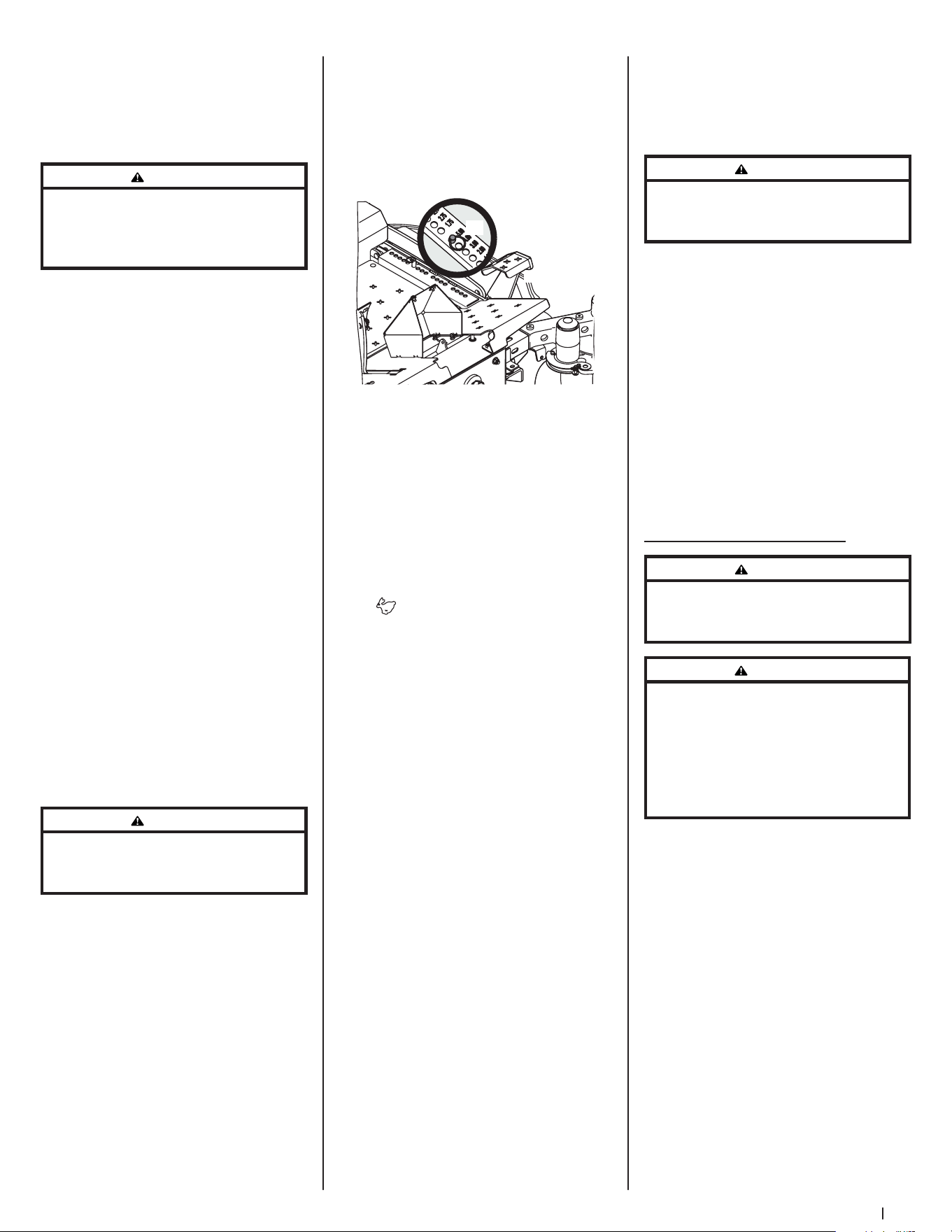
19Section 3 — controlS & operation
10. To prevent rutting or grooving of
the turf, if possible, change the
direction that the strips are mowed
by approximately 45° for the next
and each subsequent mowing.
WARNING
Be careful when crossing gravel paths or driveways.
Disengage the PTO knob and raise the deck to the
highest/transport position before crossing.
NOTE: When stopping the mower
for any reason while on a grass
surface, always:
a. Make sure the drive pedals
are in neutral.
b. Engage the parking brake.
c. Shut engine off and remove
the key.
d. Doing so will minimize the
possibility of having your
lawn ‘‘browned’’ by hot
exhaust from your mower’s
running engine.
SurePath Auto Steer System
WARNING
Make certain the area to be mowed is free of debris,
sticks, stones, wire, or other objects that can be
thrown by the rotating blades.
WARNING
The SurePath Auto Steer system will not detect
any objects or obstructions in the path of the
cutting deck or the machine. Always operate the
machine with care and attention. Stop the machine
immediately or manually steer the machine
around obstacles before resuming SurePath Auto
Steer Mode.
The SurePath Auto Steer system uses
GPS technology to semi-autonomously
control steering and turning capabilities
to achieve consistent stripes, reduce
turfing and maximize mowing efficiency.
Initializing SurePath Auto Steer Mode
1. Start the mower. See instructions
provided in Starting the
Engine section.
2. Indicator/Warning Lights will flash
blue while the SurePath Auto Steer
system is initializing.
3. Once the system has initialized,
Indicator/Warning Lights will begin
flashing green. The SurePath Auto
Steer system is actively searching
for GPS signal.
Driving on Slopes
Refer to the slope gauge in the
Practice Safe Operation section to help
determine slopes where you may not
operate safely.
WARNING
Do not operate on inclines with a slope in excess
of 20°/35% (a rise of approximately 4 feet every
10 feet). The machine could overturn and cause
serious injury.
1. Always drive across slopes, never
up and down.
2. Avoid turning downhill if possible.
Start at the bottom of a slope and
work upward. Always slow down
before turning.
3. Use extra care and go slowly when
turning downhill.
Operating the PTO knob
Operate the PTO knob as follows:
1. Move the throttle control lever (if
equipped) to approximately the
mid-throttle position.
2. Pull the PTO knob switch upward to
the ENGAGED position.
3. Advance the throttle lever
to the operating speed (full
engine speed).
4. The operator must remain in the
mower seat at all times. If the
operator should leave the seat
without turning off the power take-
off switch, the mower’s engine will
shut off.
Using the Mower Deck
WARNING
Make certain the area to be mowed is free of debris,
sticks, stones, wire, or other objects that can be
thrown by the rotating blades.
NOTE: Do not engage the mower deck
when lowered in grass. Premature wear
and possible failure of the “V” belt and
PTO clutch will result. Fully raise the deck
or move to a non-grassy area before
engaging the mower deck.
1. Use the deck lift pedal (a) to raise
the deck to its highest position,
place the clevis pin (b) attached to
the mower into the desired index
hole on the deck height index, then
slowly release the deck lift pedal (a).
See Figure 3-6.
(a)
(b)
L
o
w
e
r
Figure 3-6
2. Mow across slopes, not up and
down. If mowing a slope, start at
bottom and work upward to ensure
turns are made uphill.
3. On the first pass pick a point on
the opposite side of the area to
be mowed.
4. Engage the PTO knob and move
the throttle control to the FAST
position.
5. Remove the clevis pin, raise the
deck to the highest (transport)
position, place the clevis pin in the
desired position and secure with
the clevis pin. Lower the mower
deck to the desired height setting.
6. Slowly push the forward drive
pedal forward to move the mower
forward, and keep the mower
headed directly toward the
alignment point.
NOTE: The speed of the mower
will affect cut quality of the lawn.
Mowing at full speed will adversely
affect a high quality cut lawn.
Control the ground speed with the
drive pedals.
7. When approaching the other
end of the strip, slow down or
stop before turning. A U-turn is
recommended unless a pivot or
zero turn is required.
8. Align the mower with an edge
of the mowed strip and overlap
approximately 3”.
9. Direct the mower on each
subsequent strip to align with a
previously cut strip.
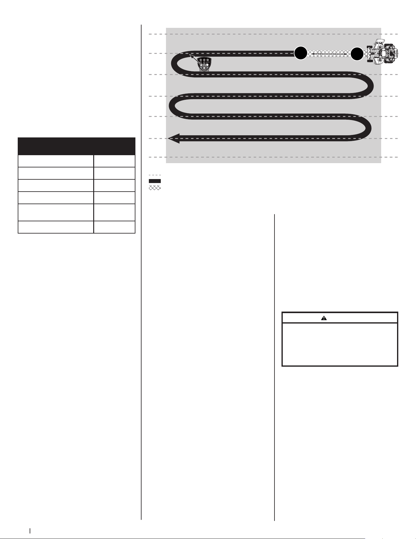
20 Section 3 — controlS & operation
Figure 3-8
IMPORTANT! Machine should
be outdoors, away from large
trees and buildings in order to
acquire signal.
NOTE: Signal acquisition will take
approximately 90 seconds.
4. Once signal is acquired, Indicator/
Warning Lights will turn solid
green. The mower is now ready
for SurePath Auto Steer Mode.
See Figure 3-7 for a list of
Indicator/Warning Light colors
and descriptions.
Descriptions
Indicator/Warning
Light Colors
System Initializing Flashing Blue
Attempting to Acquire Signal Flashing Green
Signal Acquired Solid Green
Mower Speed too Fast Flashing Yellow*
Grab and Turn Wheel to Override
SurePath Auto Steer Mode
Flashing Red
No GPS Signal Available O
*Also indicates a button press ignored by the system
Figure 3-7
Setting the Mowing Line (SurePath Auto
Steer Mode)
1. Start the mower. See instructions
provided in Starting the
Engine section.
NOTE: PTO does not need to be engaged
to set mowing line.
2. Once indicators on the Indicator/
Warning Lights are solid green, the
system is ready for SurePath Auto
Steer Mode.
3. Set your mowing line by
performing the following steps:
• Determine the first pass
location, picking a point on
the opposite side of the area to
be mowed.
• Drive in a straight line toward
point chosen in the previous
step and briefly press the SET
LINE/ENGAGE AUTO button on
the Operator Control Panel to
set point A. See Figure 3-8. The
LINE indicator will begin flashing
green when point A is set.
>10 yards (30 feet)
Left turn (as shown) or right turn*
B*
A*
SurePath Auto Steer Mowing
SurePath Auto Steer Innite Set Lines
Manual Mowing
Press and Release
*
• Continue driving in a straight
line, travel a minimum of 10
yards (30 feet), then briefly press
the SET LINE/ENGAGE AUTO
button on the Operator Control
Panel again to set point B. See
Figure 3-8. The LINE and AUTO
indicators will turn solid green
when points A and B are set.
NOTE: Once the AUTO Indicator/
on the Operator Control Panel is
solid green, the system is activated
for SurePath Auto Steer Mode and
the operator should let go of the
steering wheel.
IMPORTANT! Setting the mowing line
automatically shifts mower to SurePath
Auto Steer Mode.
Clearing the Mowing Line
(SurePath Auto Steer Mode)
To reset the system and remove the
saved points defining the mowing line:
1. Stop the mower.
2. Turn the PTO off.
3. Press and hold the SET LINE/
ENGAGE AUTO button on the
Operator Control Panel for a
minimum of 3 seconds.
NOTE: If SET LINE/ENGAGE AUTO
button is not held for a minimum
of 3 seconds, the Indicator/Warning
Lights will blink yellow once to
indicate an invalid reset.
4. LINE indicator on the Operator
Control Panel will turn off once
points A and B are cleared.
NOTE: Operator will need to reset
points A and B prior to resuming
SurePath Auto Steer Mode. Refer to
Setting the Mowing Line (SurePath
Auto Steer Mode).
NOTE: Clearing the mowing line
will automatically return mower to
manual mode.
WARNING
Holding the SET LINE/ENGAGE AUTO button for less
than 3 seconds will fail to reset line and may shift
the mower back into auto mode if preset lines
are still stored. Loss of control, property damage,
personal injury, or death may result.
Manual Override of SurePath Auto
Steer Mode
To remove the mower from SurePath
Auto Steer Mode, the operator should
resume control of the steering wheel
and turn it slightly to either the right
or left. This will return the mower to
manual mode. The AUTO indicator will
be flashing. See Figure 3-9.
To resume SurePath Auto Steer Mode,
briefly press the SET LINE/ENGAGE
AUTO button on the Operator Control
Panel. See Figure 3-9.
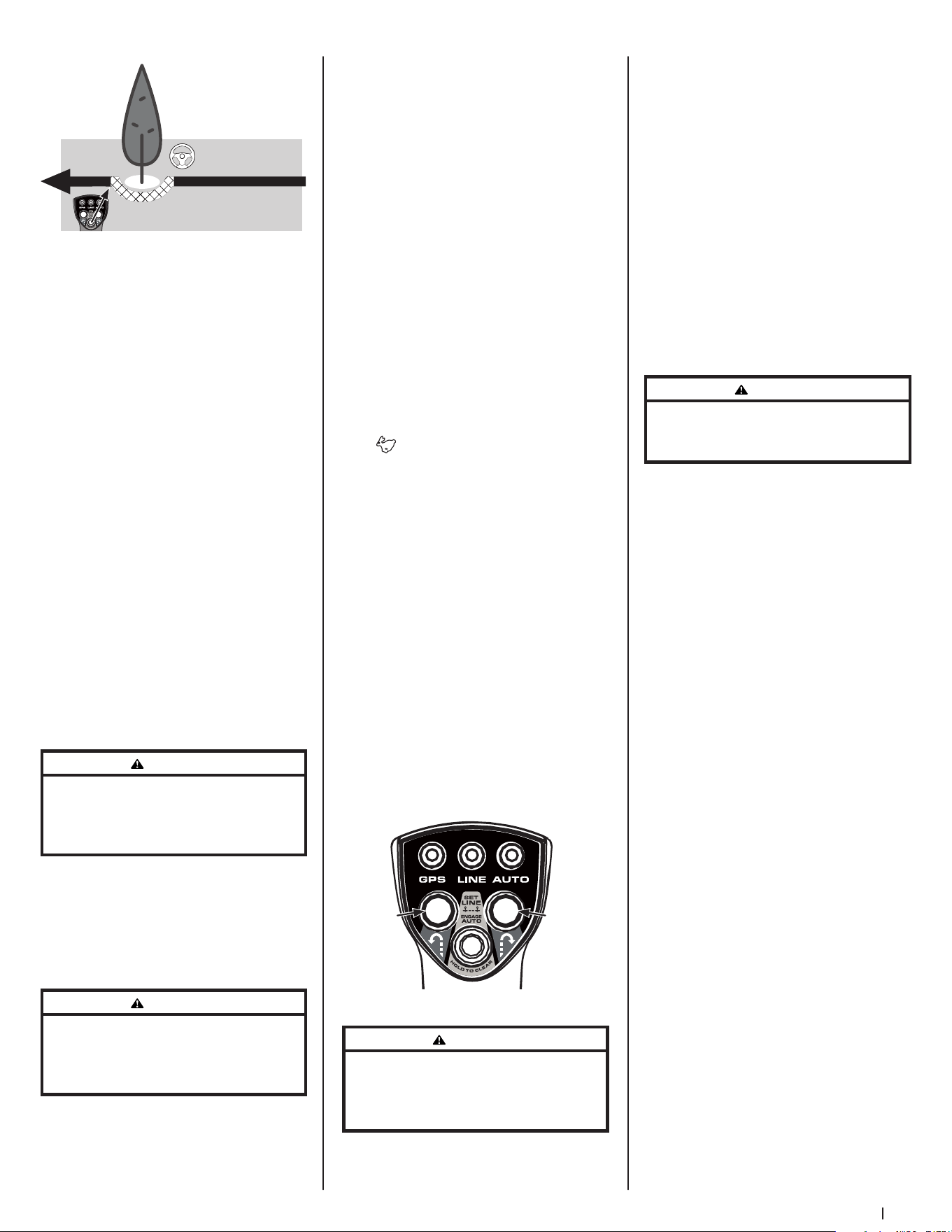
21Section 3 — controlS & operation
Briey press SET LINE/ENGAGE
AUTO button to resume Auto Steer
Manually steer
around obstacles
Figure 3-9
NOTE: Do not hold the SET LINE/
ENGAGE AUTO button down when
resuming SurePath Auto Steer Mode.
Holding the button for 3 seconds or
more will reset the system, erasing the A
and B points previously set.
Automatic Shut Off or GPM Signal Loss
If the GPM loses signal, the mower will
return to manual mode. The following
sequence will occur:
1. The Indicator/Warning Lights on
the Light Module will flash red
and the system will stop steering
the mower.
2. The operator must resume control
of the steering wheel and turn it
slightly to either the right or left to
return to manual mode.
3. Once GPS signal has been
reacquired, the Indicator/Warning
Lights will be solid green. Briefly
press the SET LINE/ENGAGE AUTO
button to resume SurePath Auto
Steer Mode.
WARNING
If the SurePath Auto Steer system malfunctions,
stop using the machine or disable the system and
have it repaired by an authorized servicing dealer
as soon as possible.
NOTE: If the SurePath Auto Steer system
malfunctions see Troubleshooting in
the Product Care section or contact an
authorized service provider.
Using the Mower Deck (SurePath Auto
Steer Mode)
WARNING
To avoid personal injury to you or others, always
use caution and be aware of your surroundings
when using the SurePath Auto Steer Mode. Stop the
machine immediately if anyone enters the area.
NOTE: Operator is always in control of
the mower’s speed and braking.
1. Use the deck lift pedal (a) to raise
the deck to its highest position,
place the clevis pin (b) attached to
the mower into the desired index
hole on the deck height index, then
slowly release the deck lift pedal (a).
Refer to Figure 3-6 on page 19.
2. Mow across slopes, not up and
down. If mowing a slope, start at
bottom and work upward to ensure
turns are made uphill.
3. To establish your mowing line
refer to Setting the Mowing Line
(SurePath Auto Steer Mode) section.
IMPORTANT! Setting the mowing line
automatically shifts mower to SurePath
Auto Steer Mode.
4. Engage the PTO knob and move
the throttle control to the FAST
position.
5. To move forward, slowly push the
forward drive pedal forward. The
SurePath Auto Steer system will
keep the mower aligned with the
preset mowing line.
NOTE: The speed of the mower
will affect cut quality of the lawn.
Mowing at full speed will adversely
affect a high quality cut lawn.
Control the ground speed with the
drive pedals.
6. When approaching the other end
of the strip, release pressure on the
forward drive pedal slightly to slow
down before initiating a right or
left zero turn. Briefly press the right
or left turn button on the Operator
Control Panel. See Figure 3-10.
Left
Zero
Turn
Right
Zero
Turn
Figure 3-10
WARNING
Do not attempt to make a turn at high speed when
using SurePath Auto Steer Mode. The system
will make smoother and more accurate turns at
lower speeds.
NOTE: Left and right turn buttons will
only function if SurePath Auto Steer
Mode has been activated.
NOTE: The SurePath Auto Steer system
will make smoother and more accurate
turns at lower speeds, and allow it
to more easily pick up and maintain
the signal for the next parallel line to
be followed.
7. Make sure mower is realigned with
mowing line before accelerating.
8. Repeat Steps 5-7 to continue
cutting parallel lines in SurePath
Auto Steer Mode.
IMPORTANT! To prevent rutting or
grooving of the turf, if possible, change
the direction that the strips are mowed
by approximately 45° for the next and
each subsequent mowing session.
WARNING
Be careful when crossing gravel paths or driveways.
Disengage the PTO knob and raise the deck to the
highest/transport position before crossing.
NOTE: When stopping the mower
for any reason while on a grass
surface, always:
a. Make sure the drive pedals
are in neutral.
b. Engage the parking brake.
c. Shut engine off and remove
the key.
d. Doing so will minimize the
possibility of having your
lawn ‘‘browned’’ by hot
exhaust from your mower’s
running engine.
9. Release pressure on forward drive
pedal slightly before initiating right
or left zero turn.
10. Make sure mower is realigned with
mowing line before accelerating.
Disabling the SurePath Auto Steer System
To prevent unauthorized use, or if the
system malfunctions, the SurePath
Auto Steer system can be disabled by
removing the GPM fuse (labeled F5:GPM
in the fuse box located under the
operator’s seat).
Forced Striping
The SurePath Auto Steer system will
force side-by-side passes to be cut in
opposite directions. This setting can be
adjusted by contacting an authorized
service center.
Calibration
See Calibration in the Product Care
section for information regarding
calibrating the SurePath Auto
Steer system.

22 Section 3 — controlS & operation
Reconfigurable Mower
Inner Baffle
Discharge
Baffle
Cutting
Blades Gauge Wheels Front Roller Rear Rollers
Standard set-up
Installed Installed Hi-lift Low = 3 to 5” Low = 3 to 5” Low = 3 to 5”
Stems (Dandelion,
Bahia, Buckhorn, etc.)
Removed Installed Hi-lift
High = 1 to 2-1⁄2”
Low = 3 to 5”
High = 1 to 2-1⁄2”
Low = 3 to 5”
High = 1 to 2-1⁄2”
Low = 3 to 5”
Very lush &/or tall grass
Removed Installed Hi-lift
High = 1 to 2-1⁄2”
Low = 3 to 5”
High = 1 to 2-1⁄2”
Low = 3 to 5”
High = 1 to 2-1⁄2”
Low = 3 to 5”
Low cut height (1 to 2”)
Installed Installed Low-lift High = 1 to 2-1⁄2” High = 1 to 2-1⁄2” High = 1 to 2-1⁄2”
Mulch
Installed Removed Hi-lift/Mulch
High = 1 to 2-1⁄2”
Low = 3 to 5”
High = 1 to 2-1⁄2”
Low = 3 to 5”
High = 1 to 2-1⁄2”
Low = 3 to 5”
Material collection
Installed Installed Hi-lift
High = 1 to 2-1⁄2”
Low = 3 to 5”
High = 1 to 2-1⁄2”
Low = 3 to 5”
High = 1 to 2-1⁄2”
Low = 3 to 5”
Abrasive (sandy), dry
Removed Installed Low-lift
High = 1 to 2-1⁄2”
Low = 3 to 5”
High = 1 to 2-1⁄2”
Low = 3 to 5”
High = 1 to 2-1⁄2”
Low = 3 to 5”
Wet
Installed Installed Hi-lift
High = 1 to 2-1⁄2”
Low = 3 to 5”
High = 1 to 2-1⁄2”
Low = 3 to 5”
High = 1 to 2-1⁄2”
Low = 3 to 5”
Table Notes: This table is a general outline of suggested settings, mowing conditions may vary.
Inner Baffle: The inner baffle regulates grass discharge. Remove the inner baffle for high-volume grass and install the inner baffle for
precision cutting.
Discharge Baffle: The discharge baffle enhances the grass discharge pattern. The discharge baffle reduces clumping and should be
removed for mulching.
Cutting Blades: The cutting blades cut grass, create grass lift and discharge grass through the discharge chute.
Gauge Wheels: The gauge wheels reduce scalping, help with precision cutting and reduce turf defacement during turns.
Front Roller: The front roller reduces scalping, helps with precision cutting and reduces turf defacement during turns.
Rear Rollers: The rear rollers reduce scalping and gives grass a striped appearance.
NOTE: To avoid damaging grass, no more than 1/3 of the grass height should be removed during a single cutting (i.e. if the grass is 6”
tall, cut it to 4”).
Mower Cutting Blades
The blades normally factory installed on
a mower afford the best grass cutting
performance on the majority of grasses
and mowing conditions; however,
there will be occasions whereby the
grass type, stage of grass growth, soil
conditions and weather conditions will
require different cutting blade types.
Since the mower decks are designed
so that over-lap of the cutting blades
generally exceed 1.5”, there is no need
for orientation of one cutting blade to
an adjacent blade (i.e., the blades do not
need to be “timed” nor synchronized).
Hi-lift — These are generally the best
cutting blades for most grasses and
mowing conditions. The Hi-Lift blades
are the factory installed blades on these
mowers. These blades will provide extra
“lift” for the thinner leaf grasses, will
handle lush grasses and will provide
maximum grass and debris discharge.
These blades are generally required
for material collection systems. More
horsepower is required for these
blades when compared to others, and
they generally produce the highest
noise levels.
Medium-lift — These blades require less
horsepower than the Hi-lift, and they
generally work well in wider leaf grasses
and some mulch applications.
Low-lift — These blades require less
horsepower than Hi-lift and Medium-lift
blades, and they generally work best
with wide leaf grasses, sparse grass
growth and sandy soil conditions.
They produce the lowest noise levels.
Low-lift blades are configured without
offset, and with a maximum amount of
sharpened cutting edge.
Mulch — These blades are generally
designed for use in cutting decks
equipped with mulch baffles. The
shape of the blade generally produces
higher turbulence in order that the grass
can be repeatedly cut and re-cut into
smaller pieces. These blades generally
require more horsepower than other
blades. Mulch blades work best when
the grasses are cut at the highest levels,
minimal lengths of grasses are removed
and grass conditions are generally dry.
NOTE: Refer to the Attachment
& Accessories section for a list of
part numbers.

Product Care 4
23
Maintenance Schedule
Before
Each Use
Every 50 Hours Every 500 Hours After Mowing
Check Gasoline Level
P
Check Hydraulic Hoses for Leaks
P
Check Tires & Tire Pressure
P
Check Deck, Mower & Hydro Drive Belts
P
Check Blades & Blade Bolt Tightness
P
Check Safety Switches for Proper Operation
P
Check Fluid Level in Transmission Oil Expansion Reservoir
P
Check/Clean Engine Intake Screens & Cooling Fans *
P P
Check/Clean Exhaust Manifold, Muer Pipe & Muer Shields *
P P
Check/Clean Top & Underside of Deck, Under & Around Spindle Covers & Belt Area *
P P
Check/Clean Around Fuses, Wiring & Wiring Harnesses *
P P
Check/Clean Around Transmission, Axle & Fans *
P P
Blow Out/Clean Pump Control Area Under Floor Pan
P
Blow Out/Clean Pedal Control Area Under Foot Rest
P
Lubricate Wear Points (see chart)
P P
Clean Engine Cooling Fins & External Surfaces *
P
Change Hydrostatic Fluid & Filter in Transaxles †
P
† — After first 300 hours, change hydrostatic fluid and filter in transaxles
* — Perform more frequently under dusty conditions
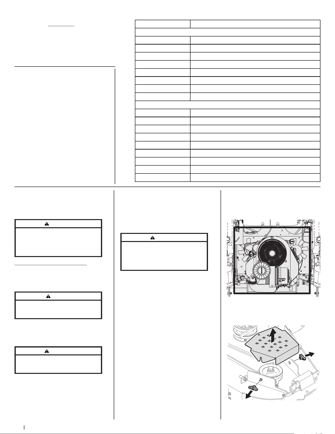
24 Section 4 — Product care
Number of Oil Points Description
DAILY
4 Deck Suspension Pivots
4 Height Adjustment Turnbuckle Clevis Pin
2 Height Adjustment Handle Pivots
2 Height Adjustment Stop Pivots
2 Deck Lift Linkage Pivots
2 Transport Handle Pivots
1 Transport Handle Pin
2 Deck Frame Up-and-Down Pivots
WEEKLY
1 Seat Hinge
2 Speed Control Linkage Rod End Bearings
2 Pump Control Lever Pivots
1 Brake Lever Pivot Clevis Pin
1 Brake Lever Control Rod Pivot
1 Brake Control Rod Swivel Joint
4 Brake Rod Clevis Pins
2 Brake Shaft Assembly Pivots
2 Grass Collection System Lid Hinges (If mower is so equipped)
OIL CHART
Apply a few drops of SAE engine oil, grease
or use a spray lubricant. Apply the oil to both
sides of pivot points. Wipe off any excess.
Start engine and operate mower briefly to
ensure that oil spreads evenly.
NOTE: This Operator’s Manual covers several
models. Mower features may vary by model.
Not all features in this manual are applicable
to all mower models and the mower
depicted may differ from yours.
WARNING
Before performing any maintenance or repairs,
disengage the PTO, move the drive pedals to the
neutral position engaging the parking brake,
stop the engine, and remove the key to prevent
unintended starting.
Post-Operation Mower Care
After each operation of the mower,
the following procedures should be
implemented to extend the life of your
mower and ensure safe operating conditions.
DANGER
Failure to follow these recommendations may result
in serious injury to yourself or others and may cause
damage to the mower.
Cleaning the Underside of the Deck
Rinse grass clippings from the deck’s
underside and prevent the buildup of
corrosive chemicals.
WARNING
Make certain the mower’s discharge chute is
directed AWAY from people, your house, garage,
parked cars, etc.
1. Disengage the PTO, set the parking
brake and stop the engine.
2. Use a hose to spray the underside of
the deck.
NOTE: Make sure that the hose is not
routed under the deck and is clear of all
moving parts.
3. After cleaning your deck, return to
the operator’s position and engage
the PTO. Keep the deck running
for a minimum of two minutes,
allowing the underside of the deck to
thoroughly dry.
Cleaning the Mower
WARNING
If the mower has been recently run, the engine,
muffler, and surrounding metal surfaces will be
hot and can cause burns to the skin. Let the engine
cool for at least five minutes. Exercise caution to
avoid burns.
Your mower should be cleaned after each
use and under certain conditions, i.e. dry
conditions and/or mulching situations,
additional cleaning may be necessary.
One of the best ways to keep your mower
running efficiently and to reduce fire risk is
to regularly remove debris buildup from the
mower. Follow the recommendations below
and contact your authorized dealer with
any questions.
• Allow the machine to cool in an open
area before cleaning.
• Do not use water on any part of the
mower except the underside of the
cutting deck. Doing so can cause
damage to the mower’s spindle
bearings, electrical system and engine,
leading to premature failures. The use
of compressed air and/or leaf blower
will help keep the mower clean.
• Clean around the exhaust manifold,
fuses, all wiring and harnesses, muffler
pipe, muffler shield, engine intake
screens and cooling fins, etc. See
Figure 4-1.
Figure 4-1
• Clean the top of the mower deck, under
the spindle covers and belt area. See
Figure 4-2.
Figure 4-2
Engine Oil
• Shell Rotella® T Triple
Protection™ 15W40
• Shell Rimula® 15W40
• Reference your Engine Operator’s
Manual for other approved options
Hydrostatic Fluid
• Drive System Fluid Plus (Shell TT-SB)
• Castrol™ (Syntec®) Edge™ 5W50
General Purpose Lubrication: Use any NLGI
Grade 2 multi-purpose grease. Shell Albida
EP2 is recommended. Shell Albida EP 2 is a
red-colored multi-purpose grease designed
for heavy-duty bearing applications. It
has high base oil viscosity for mechanical
stability, has been formulated for high load,
low-speed applications and has excellent
lubrication and corrosion protection.
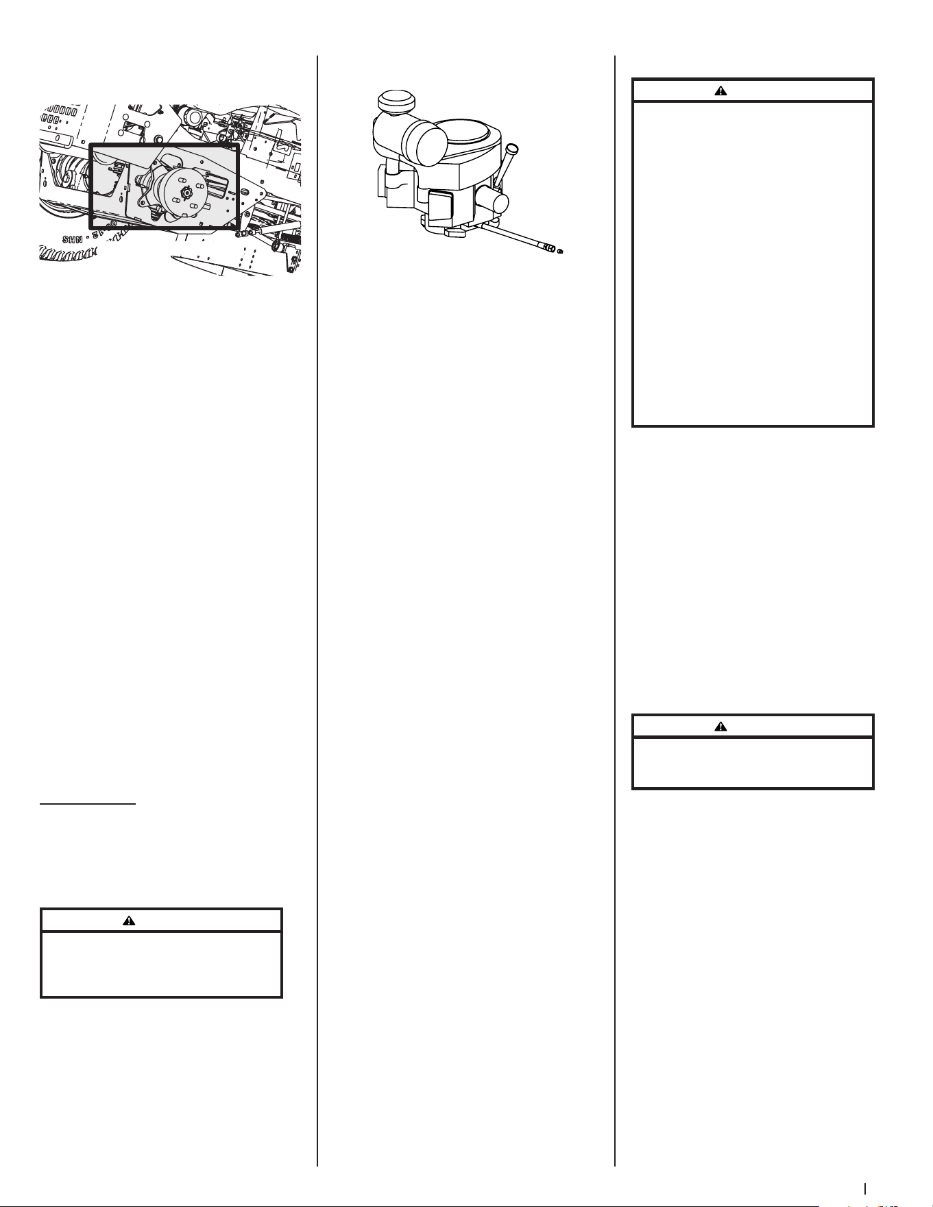
25Section 4 — Product care
• Clean around and near the
transmission, axle and the fan area. See
Figure 4-3.
Wheel Not Shown For Clarity
Figure 4-3
Storing the Mower
• Allow the machine to cool in an open
area before storing.
• Do not park the mower near any
flammable materials (wood, cloth
or chemicals) or any open flames or
other potential source of ignition
(furnace, water heater or any other type
of heater).
• Remove all combustible materials from
the mower before storing. Empty cargo
boxes, grass catchers or containers.
• Always shut off fuel flow when storing
or transporting if mower is equipped
with a fuel shutoff.
• Check the fuel system (lines, tank, cap
and fittings) frequently for cracks or
leaks. Repair and clean as necessary.
Calibration
The SurePath Auto Steer system will need to
be calibrated in the following circumstances:
• Major front end maintenance or
replacement occurs.
• GPM or complete steering column
is replaced.
Please contact an authorized service
dealer for more information regarding
system calibration.
Maintenance
Engine
Refer to the Engine Operator’s Manual for all
engine maintenance intervals, procedures,
specifications and instructions.
Changing the Engine Oil
WARNING
If the engine has been recently run, the engine,
muffler, and surrounding metal surfaces will be hot
and can cause burns to the skin. Exercise caution to
avoid burns.
Maintain oil level as instructed in Engine
Operator’s Manual. Be careful not to spill oil
on any of the belts.
To complete an oil change, proceed
as follows:
1. Run the engine for a short time to
warm the engine oil. The oil will flow
more freely and carry away more
impurities. Use care to avoid burns
from hot oil.
2. Locate the oil drain hose on the engine.
See Figure 4-4.
Figure 4-4
3. Remove the hose from the clip securing
it to the frame.
4. Route the free end of the oil drain hose
toward an appropriate oil collection
container with at least a 2.5 quart
capacity, to collect the used oil.
NOTE: Avoid getting oil on the muffler
when draining.
5. While holding the free end of the
oil drain hose over the oil collection
container, unscrew the square-head
hose plug from the end of the hose.
See Figure 4-4. Drain the engine oil into
the collection container.
6. Remove the oil filter to make sure all
the oil is drained.
7. After draining the oil, wipe any residual
oil from the oil drain hose. Thread the
square head plug into the drain hose
fitting and fully tighten the plug.
8. Replace the oil filter and refill the
engine with new oil as instructed in
the Engine Operator’s Manual. Refer
to the Engine Operator’s Manual for
information regarding the volume and
weight of engine oil.
9. Place the hose back into the clip
securing it to the frame.
Lubrication
Periodically lubricate all pivot points with a
quality lubricating oil.
Tires
Check the tire air pressure after every 50
hours of operation or weekly. Keep the tires
inflated to the recommended pressures.
Improper inflation will shorten the tire
service life and produce an uneven cut.
See the tire side wall for proper inflation
pressures. Observe the following guidelines:
• Do not inflate a tire above the
maximum pressure shown on the
sidewall of the tire.
• Do not reinflate a tire that has been run
flat or seriously under-inflated. Have it
inspected and serviced by a qualified
tire mechanic.
Battery Information
WARNING
Should battery acid accidentally splatter into
the eyes or onto the skin, rinse the affected area
immediately with clean cold water. If there is any
further discomfort, seek prompt medical attention.
If acid spills on clothing, first dilute it with clean
water, then neutralize with a solution of ammonia/
water or baking soda/water.
NEVER connect (or disconnect) battery charger clips
to the battery while the charger is turned on, as it
can cause sparks.
Keep all sources of ignition (cigarettes, matches,
lighters) away from the battery. The gas generated
during charging can be combustible.
As a further precaution, only charge the battery in a
well ventilated area.
Always shield eyes and protect skin and clothing
when working near batteries.
Batteries contain sulfuric acid and may emit
explosive gases. Use extreme caution when
handling batteries. Keep batteries out of the reach
of children.
Battery Maintenance
• The battery is filled with battery
acid and then sealed at the factory.
However, even a “maintenance free”
battery requires some maintenance to
ensure its proper life cycle.
• Spray the terminals and exposed
wire with a battery terminal sealer, or
coat the terminals with a thin coat of
grease or petroleum jelly, to protect
against corrosion.
• Always keep the battery cables and
terminals clean and free of corrosion.
• Some models are equipped with a
battery containing a liquid electrolyte.
Handle the battery with care and avoid
tipping to prevent leakage.
WARNING
Batteries contain sulfuric acid and may emit
explosive gases. Use extreme caution when handling
batteries. Keep batteries out of the reach of children.
Battery Storage
1. When storing the mower for extended
periods, disconnect the negative
battery cable. It is not necessary to
remove the battery.
2. All batteries discharge during storage.
Keep the exterior of the battery clean,
especially the top. A dirty battery will
discharge more rapidly.
3. The battery must be stored with a full
charge. A discharged battery can freeze
sooner than a charged battery. A fully
charged battery will store longer in
cold temperatures than hot.
4. Recharge the battery before returning
to service. Although the mower may
start, the engine charging system may
not fully recharge the battery.
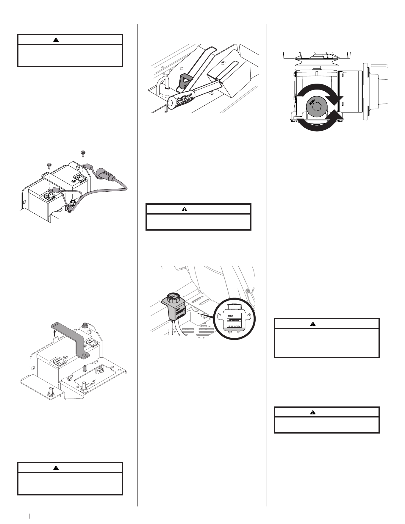
26 Section 4 — Product care
Removing the Battery
WARNING
Battery posts, terminals, and related accessories
contain lead and lead compounds. Wash hands
after handling.
1. Flip the seat all the way forward.
2. Remove the hex screw securing the
black negative battery lead (a) to the
negative battery post (marked NEG).
Move the cable away from the negative
battery post. See Figure 4-5.
3. Remove the hex screw securing the red
positive battery lead (b) to the positive
battery post (marked POS). Move the
cable away from the positive battery
post. See Figure 4-5.
(a)(a)
(b)(b)
Figure 4-5
4. Locate and hold the carriage bolt (a) at
the front of the battery bracket (c) to
prevent it from falling. See Figure 4-6.
5. Remove the hex lock nut (b) securing
the battery bracket (c) in place. Save
the carriage bolt and hex lock nut for
later reinstallation. See Figure 4-6.
6. Lift the battery bracket (c) off of the
tab at the left side of the battery
compartment and save for later
reinstallation. See Figure 4-6.
(b)(b)
(a)(a)
(c)(c)
Figure 4-6
Using the Transmission Bypass Levers
If for any reason the mower will not drive
or you wish to move the mower, the two
hydrostatic transmissions are equipped with
a bypass rod that will allow you to manually
move the mower short distances.
WARNING
Do not tow the mower, even with the bypass rod
engaged. Serious transmission damage will result
from doing so.
1. Engage the transmission bypass valves
by pulling the bypass lever (a) upward
and all the way back. See Figure 4-7.
(a)
Figure 4-7
2. To release the bypass lever (a), push the
lever forward.
Hydrostatic Transmission
The 900 series are equipped with dual
integrated hydrostatic pumps/transaxles
that are equipped with a transmission oil
expansion reservoir. Under normal operating
conditions, the oil level in the expansion
reservoir does not need to be checked and
no additional oil is needed. If checking the
reservoir oil level, proceed as follows:
WARNING
Check the oil level ONLY before starting the mower
when the transmission oil is fully cooled.
1. Pivot the operator’s seat forward and
clean the reservoir cap and the area
around the cap to prevent debris from
contaminating the transmission oil. See
Figure 4-8.
Figure 4-8
2. Turn the reservoir cap counter-
clockwise to remove, then check the
oil level in the reservoir. Oil should be
visible at the bottom of the cup, but the
oil level must NOT be above the “FULL
COLD” line. See Figure 4-8. DO NOT FILL
THE RESERVOIR.
3. If necessary to add oil because of some
type of leakage, add only enough oil to
bring the level to the “FULL COLD” line.
Reinstall the cap and fully tighten.
NOTE: Prior to the initial operation
of the mower, the oil level in the
reservoir may be slightly higher than
the maximum due to air in the oil lines.
Operation of the mower will eventually
purge the air from the lines and the oil
level will settle to the maximum.
To change the transmission oil:
1. Remove the cap from the transmission
oil expansion reservoir.
2. Place a suitable container under the
drain plug (a) on the transmission.
Remove the drain plug (a) and allow the
transmission oil to drain. See Figure 4-9.
(a)
Figure 4-9
3. Using a pair of needle-nose pliers or a
magnet remove the filter.
4. Replace the filter and drain plug
(torque to 115-135 in-lbs) and fill
through the expansion reservoir slowly
until the “FULL COLD” line. Allow the
transmission oil to move through the
system and top off as necessary.
5. Replace the cap and fully tighten.
Mower Storage
If your mower is not going to be operated
for an extended period of time (30 days
to approximately six months), the mower
should be prepared for storage. Store the
mower in a dry and protected location. If
stored outside, cover the mower (including
the tires) to protect it from the elements.
The procedures outlined below should be
performed whenever the mower is placed
in storage.
1. Change the engine oil and filter
following the instructions provided in
the Engine Operator’s Manual packed
with this manual.
WARNING
Never store the mower with fuel in the tank indoors
or in poorly ventilated enclosures, where fuel fumes
may reach an open flame, spark, or pilot light as on a
furnace, water heater, clothes dryer, etc.
a. To prevent gum deposits from
forming inside the engine’s
carburetor and causing possible
malfunction of the engine, use
a fuel stabilizer or completely
empty the fuel system for storage
between 30 and 90 days:
WARNING
Fuel left in the fuel tank deteriorates and will cause
serious starting problems.
• Read the product
manufacturer’s instructions
and recommendations.
• Add to clean, fresh gasoline
the correct amount of
stabilizer for the capacity
(approximately 3 gallons) of
the fuel system.
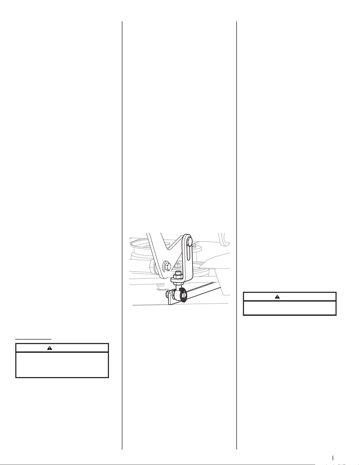
27Section 4 — Product care
• Fill the fuel tank with treated
fuel and run the engine for 2-3
minutes to get stabilized fuel
into the carburetor.
b. Emptying the fuel system for
storage of more than 90 days:
• Prior to putting the mower
in storage, monitor fuel
consumption with the goal of
running the fuel tank empty.
• Run the engine until it begins
to stall. Use the choke to keep
the engine running until all
fuel in the carburetor has
been exhausted.
• Referring to the Engine
Operator’s Manual, drain the
fuel from the carburetor bowl.
2. Clean the engine and the entire
mower thoroughly.
3. Fully charge the battery, then
disconnect the negative cable at the
battery to prevent possible discharge.
Recharge the battery periodically when
in storage.
NOTE: Remove the battery if exposed
to prolonged periods of sub-freezing
temperatures. Store in a cool, dry
location where temperatures are
above freezing.
4. Lubricate all lubrication points.
NOTE: Using a pressure washer or
garden hose is not recommended for
cleaning your mower. It may cause
damage to electrical components,
spindles, pulleys, bearings or the
engine. The use of water will result in
shortened life and reduce serviceability.
Removing the Mower from Storage
1. Check the engine oil.
2. Fully charge the battery and inflate the
tires to the recommended pressure.
3. Fill the fuel tank with clean,
fresh gasoline.
4. Start the engine and allow to idle for
a few minutes to ensure engine is
operating properly.
5. Drive the mower without a load to
make certain all the mower systems are
functioning properly.
Adjustments
WARNING
Shut the engine off, remove the ignition key,
and engage the parking brake before making
adjustments. Protect your hands by using heavy
gloves when handling the blades.
Deck Leveling
NOTE: Check the mower’s tire pressure
before performing any deck leveling
adjustments. Refer to Tires for information
regarding tire pressure. Always level the deck
side-to-side before front to rear.
Side-to-Side Leveling
1. Park the mower on a flat paved surface,
engage the parking brake, shut off
the engine, remove the key from the
ignition switch and disconnect the
spark plug wires. Using the deck lift
pedal position the mowing deck into
the 4” height of cut position (The 4”
height of cut position is recommended
in order for one to see and obtain
a measurement. Any height of cut
position is acceptable as long as a
proper measurement can be taken.)
and rotate both outside blades so that
they are perpendicular with the mower.
2. Measure the distance from the outside
of the left blade tip to the ground
and the distance from the outside
of the right blade tip to the ground.
Both measurements taken should be
equal. If they are not, proceed to the
next step.
3. Adjust the eyebolt (a) at the left front of
the deck so that the blade-to-ground
height at the right outside blade tip
matches that of the left outside blade
tip. This is done by loosening the
jam nuts (b) on the eyebolt (a) and
tightening the upper jam nut (b) to
raise the deck and loosening the jam
nut (b) to lower the deck. The right
outer blade tip height is fixed by the
right, front eyebolt (a) so you must
adjust the left outer tip to match it. See
Figure 4-10.
(a)
(b)
(b)
Figure 4-10
4. Once the proper adjustment is made,
re-tighten the jam nuts (b).
Front-to-Back Leveling
1. Park the mower on a flat paved surface,
engage the parking brake, shut off
the engine, remove the key from the
ignition switch, and disconnect the
spark plug wires. Using the deck lift
pedal position the mowing deck into
the 4” height of cut position (The 4”
height of cut position is recommended
in order for one to see and obtain
a measurement. Any height of cut
position is acceptable as long as a
proper measurement can be taken.)
and rotate both outside blades so that
they are parallel with the mower.
2. Measure the blade-to-ground height at
the right rear blade tip. Again be sure
to measure the blade tip at the rear of
the right blade when aligned along
the mower centerline. The blade-to-
ground height at the rear of the blade
tip should be 1/8” to 1/4” higher than
the front tip. This is referred to as blade
pitch. The same height difference
should be true for the left blade,
measured front and back. The pitch
should not exceed 1/16” if cut height is
below 1-1/2”.
3. Loosen the jam nuts (b) at the rear left
and right of the deck eyebolts (a). Refer
to Figure 4-10.
4. Start at the rear right to raise the rear of
the deck, tighten the upper jam nut (b)
to raise the deck or loosen the upper
jam nut (b) to lower the rear of the
deck. Refer to Figure 4-10.
5. Adjust the jam nut (b) at the rear left to
take the “slack” out of the threaded rod.
Refer to Figure 4-10.
6. Tighten both lower jam nuts (b) to
secure the deck adjustment. Refer to
Figure 4-10.
7. The final adjustment would be to take
the “slack” out of the left rear linkage
if the rear of the deck was raised by
adjusting the jam nuts (b) on the
eyebolt (a). Loosen the jam nuts (b)
and tighten the upper jam nut (b) to
remove “slack”. Refer to Figure 4-10.
8. In many cases it will be necessary to
adjust deck height using both eyebolt
(a) adjustments and pitch adjustment
to achieve the correct blade-to-ground
heights. If you remember that the front
right blade tip adjustment is fixed
and you level to that height, adjusting
the decks will be simplified. Refer to
Figure 4-10.
Adjusting the Front Gauge Wheels
WARNING
Keep hands and feet away from the discharge
opening of the cutting deck.
The front gauge wheels on the mower deck
are an anti-scalp feature, and should not
ride on the ground. The front gauge wheels
should be approximately 1/4-1/2” above the
ground when the deck is set in the desired
height setting.
Using the deck lift handle, set the deck in the
desired height setting, then check the gauge
wheel distance from the ground below. If
necessary adjust the front gauge wheels
as follows:
1. Visually check the distance between
the front gauge wheels and the
ground. If the gauge wheels are near
or touching the ground, they should
be raised. If more than 1/2” above the
ground, they should be lowered.
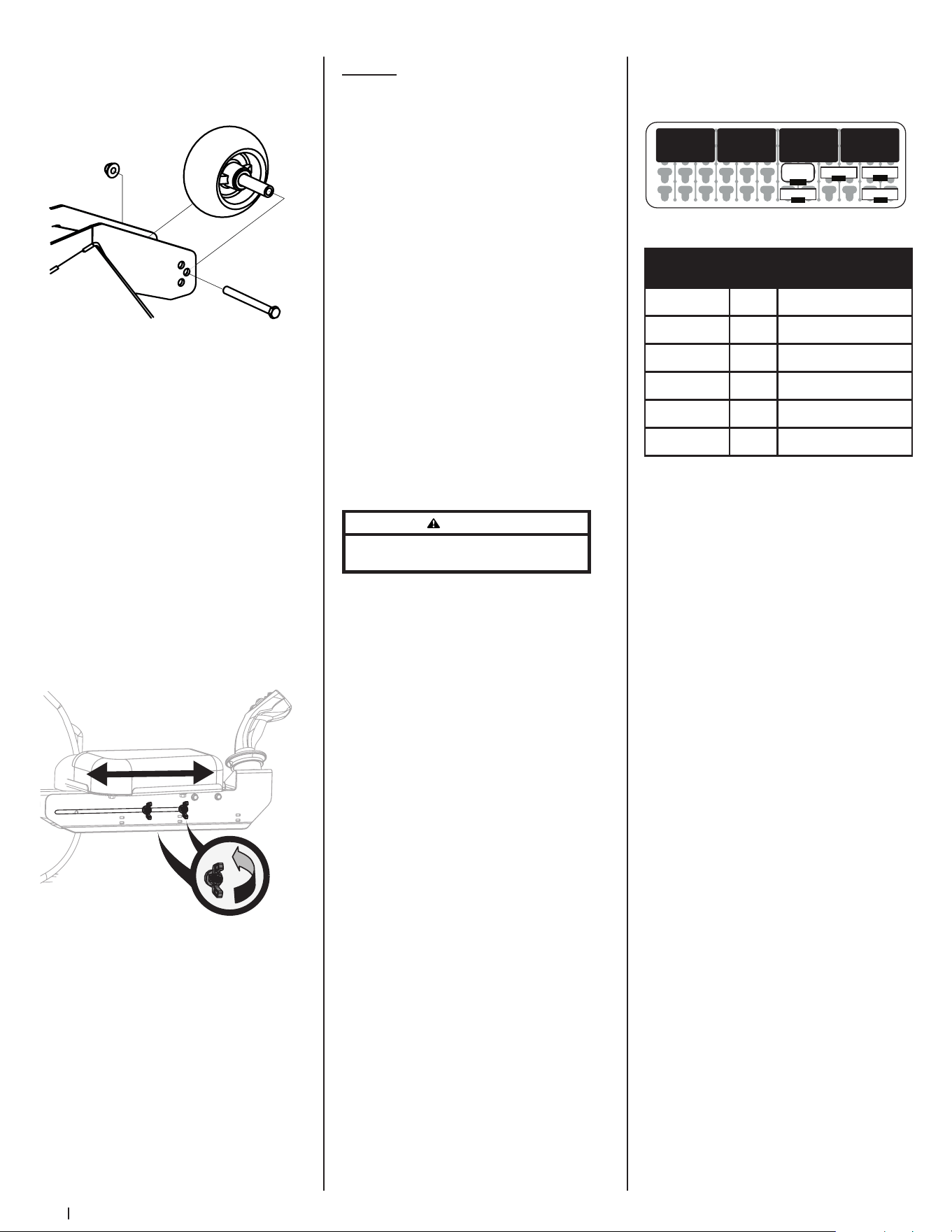
28 Section 4 — Product care
2. Remove the lock nut (a) securing one of
the front gauge wheels (b) to the deck.
Remove the front gauge wheel (b), hex
screw (c) and spacer (d). See Figure 4-11.
(a)
(b)
(c)
(d)
(e)
Figure 4-11
NOTE: There are a pair of front gauge
wheels on the nose of the 60” deck.
3. Insert the hex screw (c) into one of the
three index holes in the front gauge
wheel bracket (e) that will give the front
gauge wheel (b) a 1/4-1/2” clearance
with the ground.
4. Note the index hole of the just adjusted
front gauge wheel (b), and adjust the
other front gauge wheel (b) into the
respective index hole of the other front
gauge wheel bracket (e).
Adjusting the Operator Control
Panel Armrest
Adjust the right armrest (Operator Control
Panel side) as follows:
1. Loosen the four (4) wing nuts located
on the underside of the right armrest
by turning counter-clockwise by hand.
See Figure 4-12.
Figure 4-12
2. Slide upper portion of armrest forward
or backward until positioned to
operator preference.
3. Retighten all four wing nuts by hand to
secure armrest.
NOTE: Cable powering Operator
Control Panel runs along underside
of right armrest. Do not pinch or kink
cable while adjusting armrest.
Service
Global Positioning Module (GPM)
Do not attempt to modify or repair the GPM.
Please see an authorized service dealer for
any issues with the GPM.
Charging the Battery
Test and, if necessary, recharge the battery
after the mower has been stored for a period
of time.
A voltmeter or load tester reading of 12.4
volts (DC) or lower across the battery
terminals indicates that the battery needs to
be charged.
• An AGM battery charger should be
used. Recommended charge rate
is 1.1A/14.8V.
• If your battery charger is automatic,
charge the battery until the charger
indicates that charging is complete. If
the charger is not automatic, charge for
no fewer than eight (8) hours.
Auxiliary Alternator
Please see an authorized service dealer for
replacement of auxiliary alternator.
Jump Starting
WARNING
Failure to use this starting procedure can cause
sparking, and the gases in the battery to explode.
1. Connect the end of one cable to the
disabled machine battery’s positive
terminal; then connect the other end
of that cable to the booster battery’s
positive terminal.
2. Connect one end of the other cable
to the booster battery’s negative
terminal; then connect the other
end of that cable to the frame of the
disabled mower, as far from the battery
as possible.
3. Start the disabled mower following the
normal starting instructions previously
provided; then disconnect the jumper
cables in the exact reverse order of
their connection.
4. Have the mower’s electrical system
checked and repaired as soon as
possible to eliminate the need for
jump starting.
Servicing Electrical System
Fuse
Fuses can be found by lifting the operator’s
seat. Most of the fuses are in the main power
distribution module (PDM) to the right of the
battery (see Figure 4-13 for fuse layout and
Figure 4-14 for fuse assignments). These are
standard mini type (ATM) plug-in automotive
fuses. Always use the same capacity fuse
for replacement. Two additional fuses,
the Electronic Power Steering (EPS) and
Alternator, are in single MAXI fuse holders
near the main PDM.
If you have a recurring problem with blown
fuses, have the mower’s electrical system
checked by an authorized service dealer.
oQ
LIGHTS
R1 R2 R3 R4
DECK PWR. START
F1:Main Fuse
F2:Lights
CLUTCH
F5:GPM
-10-
F4:Start
-30-
Deck Lift
B1
-15-
-25-
-10-
Figure 4-13
Reference Value Circuits
F1: Main Fuse 25A +12V system
F2: Lights 10A Lighting system (optional)*
F4: Start 30A Starter solenoid
F5: GPM 10A Main GPM
EPS 60A Electric Power Steering
ALT 60A Alternator
*+12V system required to enable
Figure 4-14
Safety Interlock System &
Switch Operation Checks
The following operational checks should be
made daily:
PTO Switch
1. Sit in the operator’s seat. With the
drive pedals in the neutral position and
the parking brake engaged, engage
the PTO switch by pulling up on the
knob and try to start the engine. The
engine should not start. If it does, the
PTO switch must be replaced. See your
authorized service dealer.
2. If the engine does not start, disengage
the PTO by pressing the knob down
and start the engine. Now engage the
PTO and the blades should rotate.
3. If the blades do not turn, the PTO
switch must be replaced, the seat
switch must be replaced or the electric
PTO clutch must be repaired. See your
authorized service dealer.
Parking Brake Switch
1. Sit in the operator’s seat. With the drive
pedals in the neutral position and the
PTO disengaged, release the parking
brake and try to start the engine. The
engine should not start.
2. If it does, the parking brake switch
must be repositioned or replaced.
See your authorized service dealer. If
the engine does not start, engage the
parking brake and start the engine.
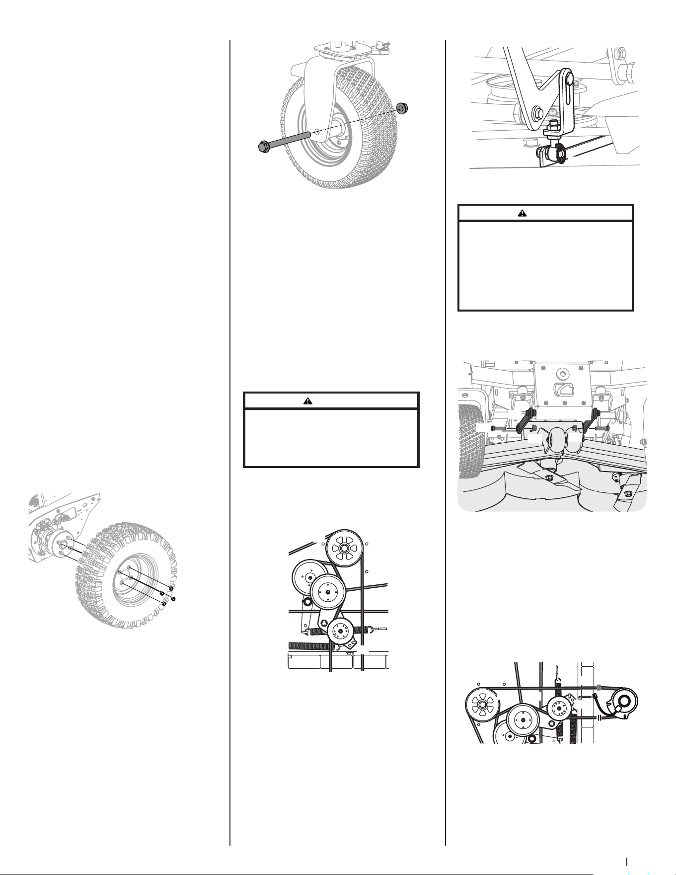
29Section 4 — Product care
Seat Switch
1. With the drive pedals in the neutral
position, the parking brake engaged
and the PTO disengaged, start the
engine. Now release the parking brake
and raise up off the seat. Release the
operator’s seat and the engine should
stop. If the engine does not stop, the
seat switch must be replaced. See your
authorized service dealer.
2. With the drive pedals in the neutral
position, the parking brake engaged
and the PTO disengaged, sit in the
operator’s seat and start the engine.
Engage the PTO and the blades should
start to rotate. Raise up slightly off the
operator’s seat and the blades should
stop. If the blades do not stop when
you dismount from the operator’s seat,
the seat switch must be replaced. See
your authorized service dealer.
Electric PTO Clutch
1. This clutch operates when the engine
is running, the operator is in the
operator’s seat and the PTO is engaged.
This electric clutch is normally a trouble
free device. If a problem develops
and the blades do not turn, first check
the 25 amp fuse, then investigate the
wiring harness and the connections to
the seat switch, the PTO switch and the
electric blade clutch. Then check the
seat switch, the PTO switch and finally
the electric blade clutch. If the PTO
clutch is still not working properly, see
an authorized service dealer.
Rear Tire Removal/Replacement
1. Remove the four lug nuts (a) to remove
the tire. See Figure 4-15.
(a)
Figure 4-15
2. Reinstall the tires using the four lug
nuts. See Figure 4-15. Torque the lug
nuts (a) to 65-70 ft-lbs.
Front Tire Removal/Replacement
1. Remove the hex screw (a) and flange
lock nut (b) that secures the front
wheel (c) to the yoke assembly (d). See
Figure 4-16.
(a)
(b)
(d)
(c)
Figure 4-16
2. To re-install or replace the front tire,
reverse Step 1. Tighten the hardware to
75-90 ft-lbs. See Figure 4-16.
Speed Sensor (Rear Tires)
Please see an authorized service dealer for
replacement or adjustment of speed sensor.
Deck Removal
Remove the mower deck from the mower
as follows:
1. Lower the deck to the ground. Capture
the deck lift by placing the clevis pin
behind the lowest position.
2. Apply the parking brake. Remove
ignition key and the spark plug cap.
WARNING
The muffler and any surrounding parts at the rear
of the mower may be extremely hot, and could
cause serious burns. Use extreme caution when near
the muffler. Allow the muffler to fully cool before
removing the belt from the PTO pulley.
3. Using a 1/2” drive in the idler pulley
bracket (a), turn the wrench towards
the right of the mower and slide the
PTO belt (b) off the PTO pulley (c). See
Figure 4-17.
(a)
(b)
(c)
Figure 4-17
4. Remove the four lynch pins (a) that
secure the deck to the deck lift
assembly. See Figure 4-18.
(a)
Figure 4-18
WARNING
The spring is under tension due to the weight of the
deck. When removing the lift linkage from the deck
the tension of the springs will go from the deck to
the deck lift pedal. Failure to capture the deck lift
pedal by placing the clevis pin behind the lowest
position while removing the lift linkage from the
deck will cause it to snap back and may result in
personal injury.
5. Remove the hex screws (a) and flange
lock nuts (b) securing the front deck
control rods (c) to the deck. See
Figure 4-19.
(a)
(a)
(b)
(b)
(c)
(c)
Figure 4-19
6. Turn front wheels as if to make a
pivot turn.
7. Shift the deck toward the right side of
the mower and remove.
8. To install reverse the process.
Replacing the PTO Belt
1. Remove the PTO belt (a) from the deck
as instructed in the Deck Removal
section then remove it from around the
PTO clutch. See Figure 4-20.
(a)
(b)
(c)
(d)
Figure 4-20
2. Route the PTO belt (a) as shown in
Figure 4-20.
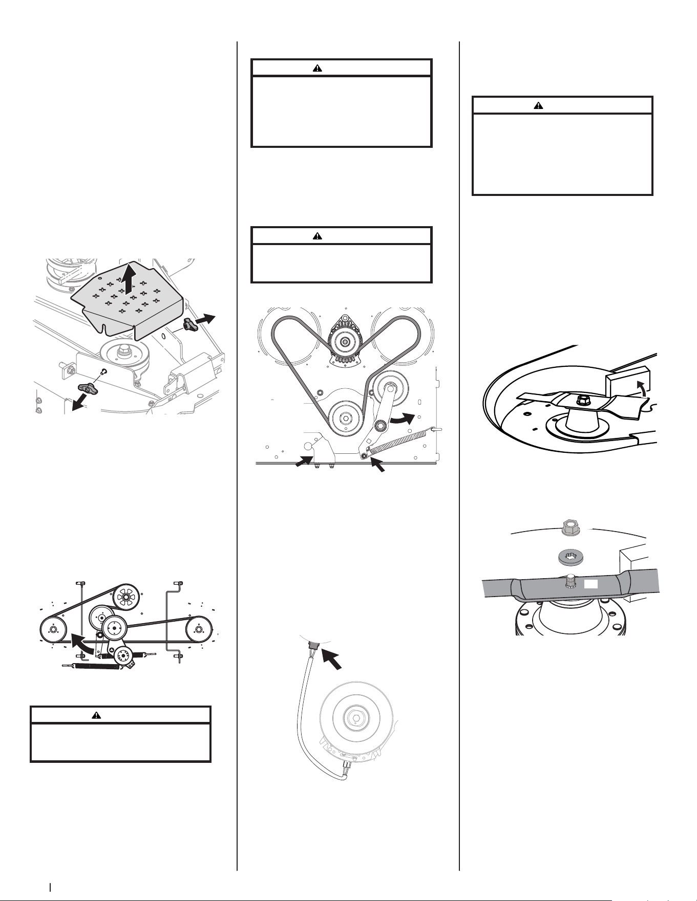
30 Section 4 — Product care
3. After routing the belt around the PTO
pulley (b), use a 1/2” drive in the idler
pulley bracket (c) and turn towards the
right of the mower to finish routing
the belt around the idler pulley (d). See
Figure 4-20.
4. Reinstall the deck by reversing the
previous steps.
Replacing the Deck Belt
1. Set the parking brake. Remove ignition
key and both spark plug caps.
2. Remove the PTO belt (refer to
Deck Removal).
3. To remove the belt covers (a), remove
the wing knobs (b) from the carriage
screws (c) securing it to the deck. See
Figure 4-21.
(a)
(b)
(c)
(b)
(c)
Figure 4-21
4. The speed nut should hold the carriage
screw (c) and tab bolt in place, if not
re-install as shown in Figure 4-21.
5. Using a 1/2” drive insert the end into
the 1/2” square opening in the deck
idler assembly (a) and rotate the deck
idler assembly (a) clockwise. See Figure
4-22. While holding the deck idler
assembly (a), loosen the deck belt from
the pulley and slide the belt away from
the pulley.
(a)
Figure 4-22
WARNING
Avoid pinching injuries. Never place your fingers
on the idler spring or between the belt and a pulley
while removing the belt.
6. Route the new belt as shown in Figure
4-22. Then reinstall the deck and
PTO belt.
Replacing the Drive Belt
WARNING
Before performing any maintenance, disengage
the PTO, engage the parking brake lever, turn the
ignition key to the OFF position, and remove the key
from the switch. Muffler and engine become hot
and can cause a burn. Allow the machine to cool at
least 5 minutes before servicing.
1. Remove PTO belt from clutch only, refer
to Deck Removal for releasing tension
on PTO belt.
2. Release tension off of idler by removing
spring from idler arm. See (a) in
Figure 4-23.
WARNING
The spring is under tension due to the weight of
the deck. Be careful when removing, may cause
personal injury. Wear gloves and safety glasses.
(a)
(b)
(c)
Hydro Transmissions Not Shown For Clarity
View Shown
from Under
Mower
Looking Up
Figure 4-23
3. Rotate idler arm out of the way of the
PTO belt. See (b) in Figure 4-23.
4. Remove anti-rotation bracket from
frame by loosening the two nuts
securing it to the deck. See (c) in
Figure 4-23.
5. Unplug electrical connector from
clutch housing. Allow to hang free for
reinstallation later in these instructions.
See Figure 4-24.
Figure 4-24
6. Remove existing drive belt.
7. Route new belt up around clutch
and engine idler pulley as shown in
Figure 4-23.
8. Reinstall the electrical connector, anti-
rotation bracket, idler arm and PTO belt
by reversing Steps 1-5.
Replacing the Blades
WARNING
Before performing any maintenance, disengage
the PTO, engage the parking brake lever, turn the
ignition key to the OFF position, and remove the key
from the switch. Protect your hands by using heavy
gloves when handling the blades. When servicing
the mower deck, be careful not to cut yourself on the
sharpened blades.
1. Remove the deck as instructed in the
Deck Removal section.
2. For easier access, flip the deck over,
then jack up the front of the deck about
one foot and block it in that position.
To remove the blade:
1. Secure the blade from turning counter-
clockwise during service by placing a
block of wood between the blade and
the deck housing, see Figure 4-25, or
wrap a rag around one end of the blade
and grasp the blade firmly.
Figure 4-25
2. Remove the flange lock nut (a) and flat
washer (b) from the spindle shaft and
remove the blade (c). See Figure 4-26.
(b)
(c)
(a)
Figure 4-26
To replace or reinstall the blade:
1. Put the blade in place on the spindle
shaft. Be sure to install the blade with
the side marked “Bottom”, “Grass
Side” or with a part number stamped
facing the ground when the deck is
reinstalled on the mower and in the
operating position.
2. Carefully place the flat washer on the
spindle shaft. Be sure that the splines
at the base of the spindle shaft threads
line up with the washer splines. See
Figure 4-27.
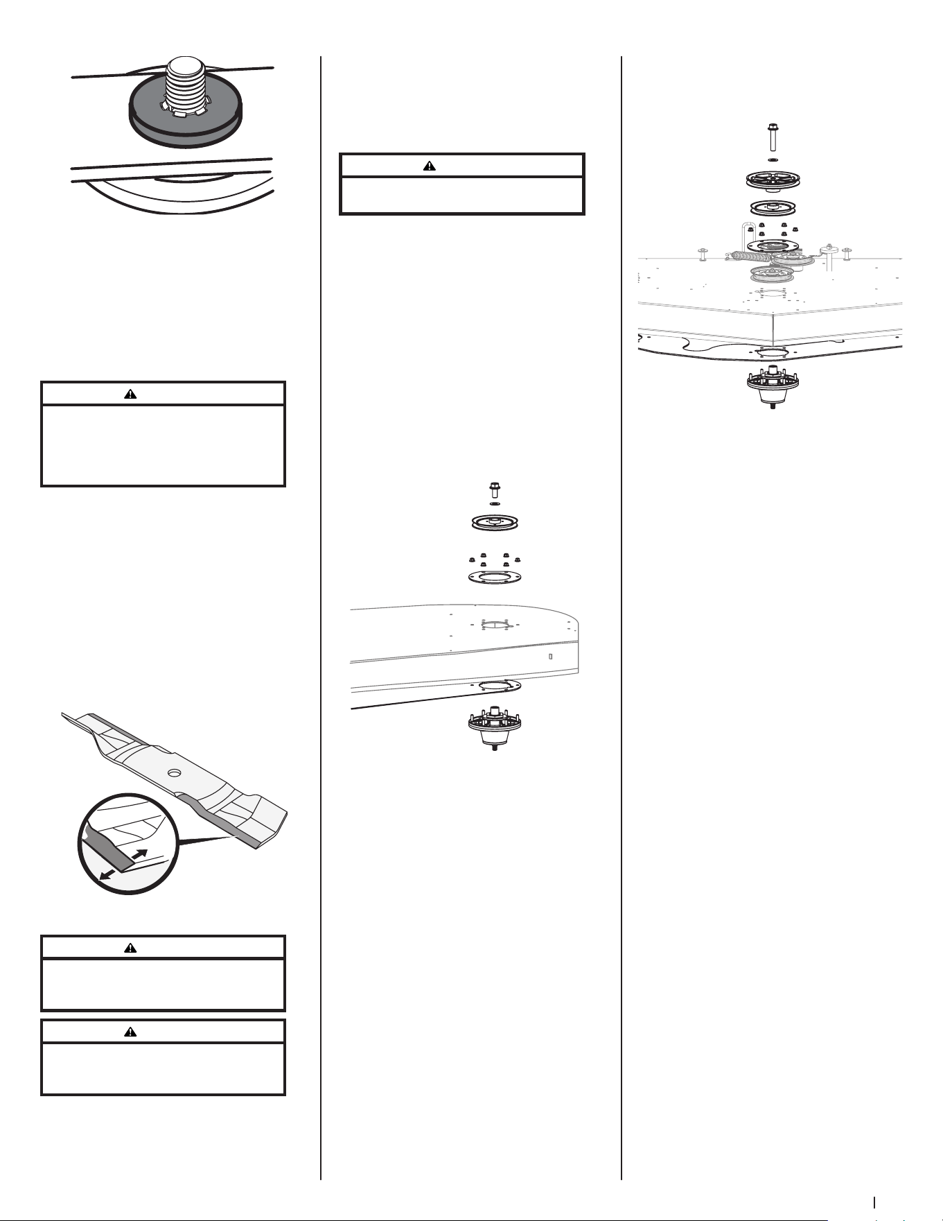
31Section 4 — Product care
Figure 4-27
3. Secure the blade from turning
clockwise when reinstalling the flange
lock nut (the opposite direction of
blade removal).
4. Install the flange lock nut onto the
spindle shaft over the blade and flat
washer. Torque to 100-130 ft-lbs (136-
176 N -m).
WARNING
Never mow with dull blades. Blades that are bent
should be replaced. The cutting blades are sharp and
can cause severe injury. Wrap the cutting surface
of the blade with a rag and wear heavy gloves to
avoid injury.
Sharpening the Blades
1. Set the parking brake.
2. Clean any debris from the blades. Keep
blades sharp and free of build up at
all times.
3. To properly sharpen the cutting blades,
remove equal amounts of metal from
both ends of the blades along the
cutting edges, parallel to the trailing
edge, at a 25°-30° angle. Always grind
each cutting blade edge equally to
maintain proper blade balance. See
Figure 4-28.
Figure 4-28
WARNING
If a blade is bent or otherwise damaged, replace
the blade with a new one. Use only original
equipment blades.
WARNING
A poorly balanced blade will cause excessive
vibration, may damage the machine, and/or result in
personal injury.
4. Test the blade’s balance using a blade
balancer. Grind metal from the heavy
side until it balances evenly.
NOTE: When replacing the blade, be
sure to install the blade with the side of
the blade marked ‘‘Bottom’’ or “Grass
Side” (or with a part number stamped
in it) facing the ground when the
mower is in the operating position.
WARNING
Use a torque wrench to tighten the blade spindle hex
flange nut to between 100 ft-lbs and 130 ft-lbs.
Changing the Spindle Assembly
1. Remove the deck as instructed in the
Deck Removal section.
2. Jack up the front of the mowing
deck about one foot and block it in
that position.
3. Remove the deck cover.
4. Remove the drive belts. See Replacing
the Drive Belt.
5. Remove the blade. See Replacing
the Blades.
6. Remove the hex flange bolts (a) and
flat washers (b) securing the left and
right spindle pulleys (c) to the spindle
assembly (d). See Figure 4-29.
(e)
(g)
(f)
(c)
(d)
(a)
(b)
(h)
Figure 4-29
7. Remove the six (6) flange lock nuts
(e) securing the left and right spindle
assemblies (d) and the support plates
(f) to the deck shell (g). See Figure 4-29.
NOTE: The deck support plate (h) does
not need to be removed unless all
three spindles are being replaced. See
Figure 4-29.
8. Remove the hex flange bolt (a) and flat
washer (b) securing the drive pulley
(c) and center spindle pulley (d) to the
spindle assembly (e). See Figure 4-30.
(f)
(e)
(g)
(c)
(d)
(a)
(b)
(h)
(i)
Figure 4-30
9. Remove the six (6) flange lock nuts
(f) securing the center (d), spindle
assembly (e) and the support plates (g)
to the deck shell (h). See Figure 4-30.
NOTE: The deck support plate (i) does
not need to be removed unless all
three spindles are being replaced. See
Figure 4-30.
10. Reverse the process to install the
spindle assembly. When installing
the new spindle assembly be sure to
install the hardware exactly as shown in
Figure 4-29. Torque the hex flange bolts
to 250 ft-lbs and the flange lock nuts to
21-32 ft-lbs.
Changing the Transmission Drive Belt
Several components must be removed
and special tools used in order to change
the mower’s transmission drive belt. See
your authorized service dealer to have the
transmission drive belt replaced.
Mower Creeping
Creeping is the slight forward or backward
movement of the mower when the throttle
is on and the speed control pedals are in the
neutral position. If your mower creeps, see
your authorized service dealer.
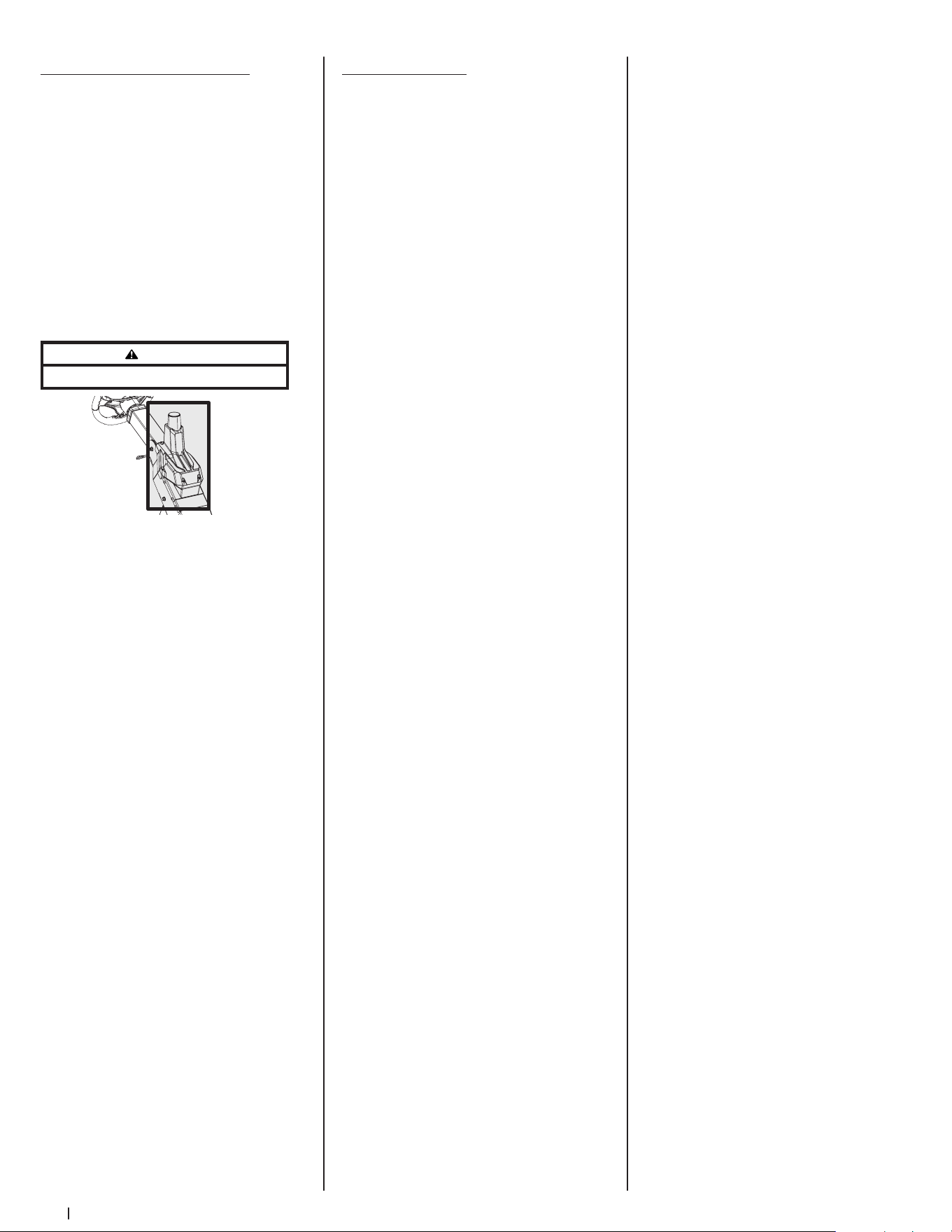
32 Section 4 — Product care
SurePath Auto Steer System
NOTE: SurePath Auto Steer system
functionality requires connectivity to
software and services. The first year of your
subscription is included in the price of the
product. All following years will need to be
renewed at the current subscription cost. For
more details, and to purchase a subscription,
please visit cubcadet.com/surepath.
Maintenance
• Never wash the GPM. If necessary, wipe
the GPM with a clean micro-fiber towel
only. Never cover the GPM antenna.
Covering the GPM antenna, even with
certain kinds of stickers, will inhibit GPS
signal which will disable autonomous
function. See Figure 4-31.
WARNING
Do not block GPM.
Figure 4-31
• Debris can accumulate anywhere on
the mower, especially on horizontal
surfaces. Additional cleaning may
be necessary when mowing in dry
conditions or when mulching.
• Fuel leaks/spills, oil leaks/spills and
excess lubrication can also become
collection sites for debris. Immediate
repair and cleaning up oil or fuel spills
can help reduce fire hazards.
• In addition to cleaning the mower
before operating and storing, do not
attempt to mow unusually tall grass (10”
or higher), dry grass (e.g., pasture) or
piles of dry leaves. Dry grass or leaves
may contact the engine exhaust and/or
build up on the mower deck presenting
a potential fire hazard.
Global Positioning Module (GPM)
Do not attempt to modify or repair the GPM.
Please see an authorized service dealer for
any issues with the GPM.
Troubleshooting
Excessive vibration
1. Cutting blade loose or unbalanced.
• Tighten blade and spindle.
2. Damaged or bent cutting blade.
• Replace blade.
Uneven cut
1. Deck not properly leveled.
• Perform side-to-side
deck adjustment.
2. Cutting blade dull or damaged.
• Sharpen or replace cutting blade.
3. Uneven tire pressure.
• Check and correct tire pressure in
all four tires.
Mower will not mulch grass
1. Engine speed too low.
• Place throttle in FAST
(rabbit) position.
2. Wet grass.
• Do not mulch when grass is wet.
3. Excessively high grass.
• Mow once at a high cutting height,
then mow again at desired height
or make a narrower cutting swath.
4. Dull blade.
• Sharpen or replace blade.
Engine fails to start
1. PTO/Blade engaged.
• Place blade engage lever in
disengaged (OFF) position.
2. Blown fuse.
• Replace fuse(s). Replace with same
rating fuse, if necessary.
3. Parking brake not engaged.
• Engage parking brake.
4. See Engine Operator’s Manual.
SurePath Auto Steer System
NOTE: SurePath Auto Steer system issues
may be resolved by turning the mower off,
waiting 10 seconds and then turning the
mower back on.
1. Indicator/Warning Lights do not flash
blue after key is turned on.
• Check fuses. Replace with same
rating fuse, if necessary.
2. Indicator/Warning Lights do not go
solid green.
• Move away from trees and
buildings. Ensure nothing is
blocking the GPM.
3. Mower is in an open area but Indicator/
Warning Lights stay flashing green.
• Check for strength of
cellular signal.
• Verify SurePath Auto Steer
subscription is still active.
• Check if mower has been
moved out of the state(s) where
SurePath Auto Steer subscription
was activated.
• Contact an authorized service
dealer if the above items
are resolved.
4. Indicator/Warning Lights flash yellow
when you press a button.
• SurePath Auto Steer system is not
ready. Wait for GPS indicator to be
solid green.
5. GPS indicator is ON but SurePath Auto
Steer Mode will not engage.
• Resume use in manual mode and
contact an authorized service
dealer to review active faults.
6. Indicator/Warning Lights flash red
while system is being used in SurePath
Auto Steer Mode.
• Move away from trees and
buildings and verify nothing is
blocking the GPM.
• Check for strength of
cellular signal.
• Resume use in manual mode and
contact an authorized service
dealer to review active faults.
7. Indicator/Warning Lights flash red.
• Resume use in manual mode and
contact an authorized service
dealer to review active faults.
8. SurePath Auto Steer Mode leaves uncut
areas between mowing passes.
• Turn Cutting Width knob
counter-clockwise to increase
mowing overlap.
9. SurePath Auto Steer Mode is
overlapping too much between
mowing passes.
• Turn Cutting Width knob clockwise
to reduce mowing overlap.
10. SurePath Auto Steer Mode needs to
be disabled.
• Remove GPM fuse (labeled F5:GPM
in the fuse box located under
the operator’s seat) to disable
SurePath Auto Steer system.
• Contact an authorized
service dealer.

33
Replacement Parts
5
Part Number Description
954-04319 Deck Belt
954- 05128
954- 05129
PTO Belt (60” Deck)
PTO Belt (72” Deck)
754P06974 Drive Belt
942-04415
742-04415-ES
942- 05179
Hi-Lift Blade, 21.0 (60” Deck)
Eversharp™ Hi-Lift Blade, 21.0 (60” Deck)
Hi-Lift Blade, 25.0 (72” Deck)
918-08473 Deck Spindle
634-05451 Deck Wheel
731-11926 Deck Skid Guard
951-15243 Gas Cap
946-05260 Throttle Control Cable
946- 05341B Choke Control
925-06908 Ignition Key
946-05103A Park Brake Cable
931-05396C
931- 05419
Chute Assembly (60” Decks)
Chute Assembly (72” Decks)
634-05192
634-05428B
Rear Wheel Assembly, 26 x 12-12
Front Wheel Assembly 16 x 6.5-8
02003749 Front Axle Wear Plates, 1.125 x 5.0
741-0941A Front Axle Ball Bearings, 1.0 x 52 x 15
Attachments & Accessories
6
Part Number Description
59A30060150 Triple Bagger
59A30062150 60” Blower Kit
59A30063150 60” Bagger Fan
19B70039100 60” Mulch Kit
59A30053150 72” Mulch Kit
490-241- 0036 Rear Tire Chain Kit
59 B30 021150 12V Outlet Receptacle
59 B30 011150 Work Light Kit
59A30018150 Caster Wheel Kit
Part Number Description
59A30057150 Ultra Traction Tire, 26 x 12-12
59A30058150 Ultra Traction Tire, 24 x 12-12
59C30052150 Heavy Duty Striping Roller
490-850-0008 Oil Siphon
490-850-0005 Blade Removal Tool
490-325-0020 Tire Sealant
490-900-0045 Oil Filter Wrench
490-900-0062 Armortek Non-Stick Spray
490-000-0028 Carburetor & Choke Cleaner

34
Notes

CUB CADET LLC -- LIMITED WARRANTY
100016 Rev I (January 8, 2021)
The limited warranty set forth herein is given by Cub Cadet LLC with respect to a new Cub Cadet® product (hereinafter “Product”) purchased and used in the
United States and/or Canada to the Initial Purchaser (as defined herein). This limited warranty does not cover Emission Control Systems and is not a Federal
Emission Control Warranty Statement, as defined by U.S. federal law. Please refer to the Federal Emission Control Warranty Statement in the operator’s manual
for warranties covering Emission Control Systems.
Scope of the Limited Warranty
Cub Cadet LLC warrants that the Product (except with regard to the components and circumstances defined below as “Exclusions”) will be free from defects in
materials and workmanship during the Warranty Period, as defined below. For purposes of this limited warranty, the “Initial Purchaser” is the first person/company
to purchase this new Product from an authorized Cub Cadet dealer, distributor, and/or retailer of such products, including a party for whom said Product was
purchased as a gift. This limited warranty is non-transferrable. During the Warranty Period, Cub Cadet LLC will, at its option, either repair or replace any original
part that is covered by this limited warranty and is determined to be defective in workmanship or material. “Commercial Use” shall be defined as any commercial,
professional, agricultural, institutional, or income-producing use of the Product. See notes below as to Commercial Use Warranty.
Cub Cadet® Warranty Information
Handheld Product* Warranty Period
Chainsaws, Cultivators, Blowers, Brushcutters, Trimmers 3 Year
Wheeled Chore and Snow Product*
Chipper-Shredders, Chipper-Shredder Vacuums, Blowers, Log Splitters, Snow Blowers 3 Year
Tillers, String Trimmers, Lawn Edgers, Pressure Washers CC3224, CC3425 & CC4033 3 Year†
Pressure Washers 2 Year†
Battery Powered Product
60 Volt Max Product Series, CC30E, XT1 LT42E, ZT1 42E 3 Year†
60 Volt Max Product Series, CC30E, XT1 LT42E, ZT1 42E Batteries 4 Year†
Gas Powered Product
Ultima ZTX Series 4 Year/500 hour (whichever comes first)
Z-Force SX 4 Year/500 hour (whichever comes first)
Walk-Behinds, Wide-Area Walk-Behinds, CC30 Riders, XT1 & XT2 Enduro Series, RZT S/SX, Ultima ZT Series,
Z-Force S
3 Year†
23” Walk-Behinds, XT3 Enduro Series 4 Year†
Rotary Spreader 1 Year
Gas Blowers, PRO HW, PRO X-636 2 Year
PRO Z 500/700/900, PRO X-648/654/660, TANK LZ/SZ 3 Year
PRO Z 100 S 2 Year/NHL (No Hour Limit) or 4 Year/500 hour
(whichever comes first)
Utility Vehicle*
Challenger Series, Volunteer Series 1 Year
Additional Warranty Notes
Lead-Acid Batteries: Are covered by a one (1) year prorated limited warranty against defects in material and workmanship, with 100% replacement during
the first three (3) months, from the date of original purchase by the Initial Purchaser. After three (3) months, the battery replacement credit is based on the
months remaining in the twelve (12) month period, dating back to the date of original purchase by the Initial Purchaser. Any replacement battery will be
warranted only for the remainder of the original warranty period.
Frames: The frame, chassis, and front axle on all XT1, XT2 and XT3 products are covered for “Residential Use” by a five (5) year limited warranty. The frame on
all Ultima ZT and ZTX series products are covered for “Residential Use” by a seven year Limited Lifetime Warranty.
Mowing Decks: 1) Cub Cadet LLC warrants the mowing decks under the warranty of the product it came with unless otherwise stated. 2) When so equipped,
the optional fabricated cutting deck shell (excluding wear parts, etc. thereon) shall be warranted against defects in material and workmanship for the lifetime
of the product, namely for as long as it is owned by its Initial Purchaser or the party for whom it was originally purchased as a gift, or seven (7) years from the
date of its initial sale to an Initial Purchaser, whichever comes first. 3) The deck shell, deck spindles, and deck steel pulleys (collectively the “Deck Assembly”)
on PRO Z 500 / 700 / 900 and PRO X-600 product only, shall also be warranted to be free from defects in material and workmanship for up to an additional
two (2) years (a total of five (5) years from date of purchase) or 1,750 cumulative hours of operation, whichever comes first. For purposes of clarity, no hour
limitation applies during the initial three (3) year period described above.
Snow Blowers: Three-Stage and Two-Stage (excluding 2X 24 models) - Auger gear boxes have a five (5) year limited warranty.
L and S Series: RZT L/LX, Z-Force L/LX/SZ, PRO Z 100 L, Z-Force Commercial (LZ/SZ), and Tank (L/S): Please refer to warranty included with Operator’s
Manual.
Attachments/Accessories: Please refer to warranty with Operator’s Manual.
*Limited Commercial Use Warranty: Handheld products – 90 days; Chipper-Shredder Vacuums, Blowers, Log Splitters, Snow Blowers – 1 year;
Utility Vehicle – 6 month.
† No Commercial Use Warranty: Tillers, String Trimmers, Lawn Edgers, Pressure Washers, Battery Powered Product, Walk Behind Mowers, 60 Volt Max
Product Series, CC30 Riders, Enduro Series, RZT S/SX, Ultima ZT Series, and Z-Force.
The limited warranty is non-transferrable

How to Get Service Under This Limited Warranty
In order to qualify for the limited warranty, as set forth herein, the repairs
made under this warranty must be performed by an authorized Cub Cadet
service provider. To locate a Cub Cadet service provider, contact your
authorized Cub Cadet dealer, distributor, or retailer, or contact Cub Cadet
LLC at P.O. Box 368023, Cleveland, Ohio 44136-0019, or call 1-877-282-8684,
or log on to our Website at www.cubcadet.com. For Canada, contact MTD
Products Limited, 97 Kent Ave, Kitchener, ON N2G 3R2, or call 1-800-668-1238,
or log on to our Website at www.cubcadet.ca. This limited product warranty is
provided by Cub Cadet LLC and is the only product warranty provided by Cub
Cadet LLC for the Product. A COPY OF YOUR SALES RECEIPT IS REQUIRED FOR
WARRANTY SERVICE.
What This Limited Warranty Does Not Cover
This limited warranty does not cover the following (the “Exclusions”):
1. Product purchased outside of the United States or Canada.
2. Emission Control Systems. These items are subject to a separate warranty
under the applicable Federal Emission Control Warranty Statement.
Please refer to the applicable Federal Emission Control Warranty
Statement for terms and conditions relating to Emission Control Systems.
3. Damage due to lack of maintenance and/or improper maintenance, as
described in the operator’s manual.
4. Normal wear and tear resulting from use of the Product.
5. Normal Wear Parts (as defined herein) are warranted to be free from
defects in material and workmanship for a period of thirty (30) days from
the date of original purchase by the Initial Purchaser for residential use,
and for 30 days or 100 hours (whichever occurs first) for Product used
commercially. Depending on Product, Normal Wear Parts include, but
are not limited to items such as: belts, blades, blade adapters, grass bags,
rider deck wheels, seats, shave plates, skid shoes, tines, filters, nozzles,
hoses, O-rings, spray guns, wands, tires, spark plugs, fuses, bump knobs,
outer spools, cutting line, inner belts, starter pulley, starter rope, drive
belts, saw chains, guide bars, and other consumable items.
6. Log splitter pumps, valves, and cylinders are covered for a period of one
(1) year.
7. Use of the product that is not consistent with the intended use thereof,
as described in the operating instructions, including, but not limited
to, abuse, misuse and/or neglect of the Product, or any use inconsistent
with and/or non-compliant with instructions contained in the Operator’s
Manual. This includes operation in sandy and/or corrosive environments.
8. Any Product that has been altered or modified in a manner not
consistent with the original design of the Product or in a manner not
approved by Cub Cadet LLC.
9. Paint repairs or replacements for defective paint (including materials and
application) are covered for a period of three (3) months.
10. Wheel rims (when so equipped) are covered for a period of three (3)
months for manufacturing defects.
This warranty does not cover, and Cub Cadet LLC disclaims any
responsibility for, matters including, but not limited to, the following:
1. Loss of time or loss of use of the Product.
2. Transportation costs and other expenses incurred in connection with the
transport of the Product to and from the authorized Cub Cadet service
provider.
3. Any loss or damage to other equipment or personal items.
4. Damages caused by improper maintenance or the use of other than the
specified fuel, oil, or lubricants, as approved in the operator’s manual.
5. Damage resulting from the installation or use of any accessory or part
not approved by Cub Cadet LLC for use with the Product.
Limitations
1. THERE ARE NO IMPLIED WARRANTIES, INCLUDING, BUT NOT LIMITED
TO, ANY IMPLIED WARRANTY OF MERCHANTABILITY OR FITNESS FOR
A PARTICULAR PURPOSE. NO WARRANTY SHALL APPLY AFTER THE
APPLICABLE WARRANTY PERIOD, AS SET FORTH ABOVE, AS TO THE
PARTS AS IDENTIFIED. NO OTHER EXPRESS WARRANTY OR GUARANTY,
WHETHER WRITTEN OR ORAL, EXCEPT AS MENTIONED ABOVE, GIVEN
BY ANY PERSON OR ENTITY, INCLUDING A DEALER OR RETAILER, WITH
RESPECT TO ANY, PRODUCT SHALL BIND CUB CADET LLC. DURING
THE WARRANTY PERIOD, THE EXCLUSIVE REMEDY IS REPAIR OR
REPLACEMENT OF THE DEFECTIVE PART, AS SET FORTH ABOVE. (SOME
STATES DO NOT ALLOW LIMITATIONS ON HOW LONG AN IMPLIED
WARRANTY LASTS, SO THE ABOVE LIMITATION MAY NOT APPLY TO YOU.)
2. THE PROVISIONS, AS SET FORTH HEREIN, PROVIDE THE SOLE AND
EXCLUSIVE REMEDY ARISING FROM THE SALE. CUB CADET LLC SHALL
NOT BE LIABLE FOR INCIDENTAL OR CONSEQUENTIAL LOSS OR DAMAGES
INCLUDING, WITHOUT LIMITATION, FOR TRANSPORTATION OR FOR
RELATED EXPENSES, OR FOR RENTAL EXPENSES TO TEMPORARILY
REPLACE A WARRANTED PRODUCT. (SOME STATES DO NOT ALLOW
THE EXCLUSION OR LIMITATION OF INCIDENTAL OR CONSEQUENTIAL
DAMAGES, SO THE ABOVE EXCLUSION OR LIMITATION MAY NOT APPLY
TO YOU.)
3. IN NO EVENT SHALL RECOVERY OF ANY KIND BE GREATER THAN THE
AMOUNT OF THE PURCHASE PRICE OF THE PRODUCT SOLD. ALTERATION
OF THE SAFETY FEATURES OF THE PRODUCT SHALL VOID THIS LIMITED
WARRANTY. YOU ASSUME THE RISK AND LIABILITY FOR LOSS, DAMAGE,
OR INJURY TO YOU AND YOUR PROPERTY, AND/OR TO OTHERS AND
THEIR PROPERTY, ARISING OUT OF THE USE OR MISUSE OR INABILITY TO
USE THE PRODUCT.
4. This limited warranty extends to the Initial Purchaser only and, except
as otherwise stated herein, the applicable Warranty Period will begin
on the original date of purchase of the Product. In the event that the
original date of purchase of the Product is indeterminable, then the
Warranty Period shall be established as beginning on the Product’s date
of manufacture, as determined by Cub Cadet LLC, and ending six (6)
months after the applicable Product Warranty Period, as defined above.
In no event shall a Product’s warranty extend beyond the applicable
Warranty Period.
How State Law Relates to This Warranty
This limited warranty gives you specific legal rights, and you may also have
other rights, which vary from state to state.
100016 Rev I (January 8, 2021)
