
22
MILWAUKEE TOOL
l
www.milwaukeetool.com
13135 W. LISBON RD., BROOKFIELD, WI 53005
Drwg. 1
FIG. PART NO. DESCRIPTION OF PART NO. REQ.
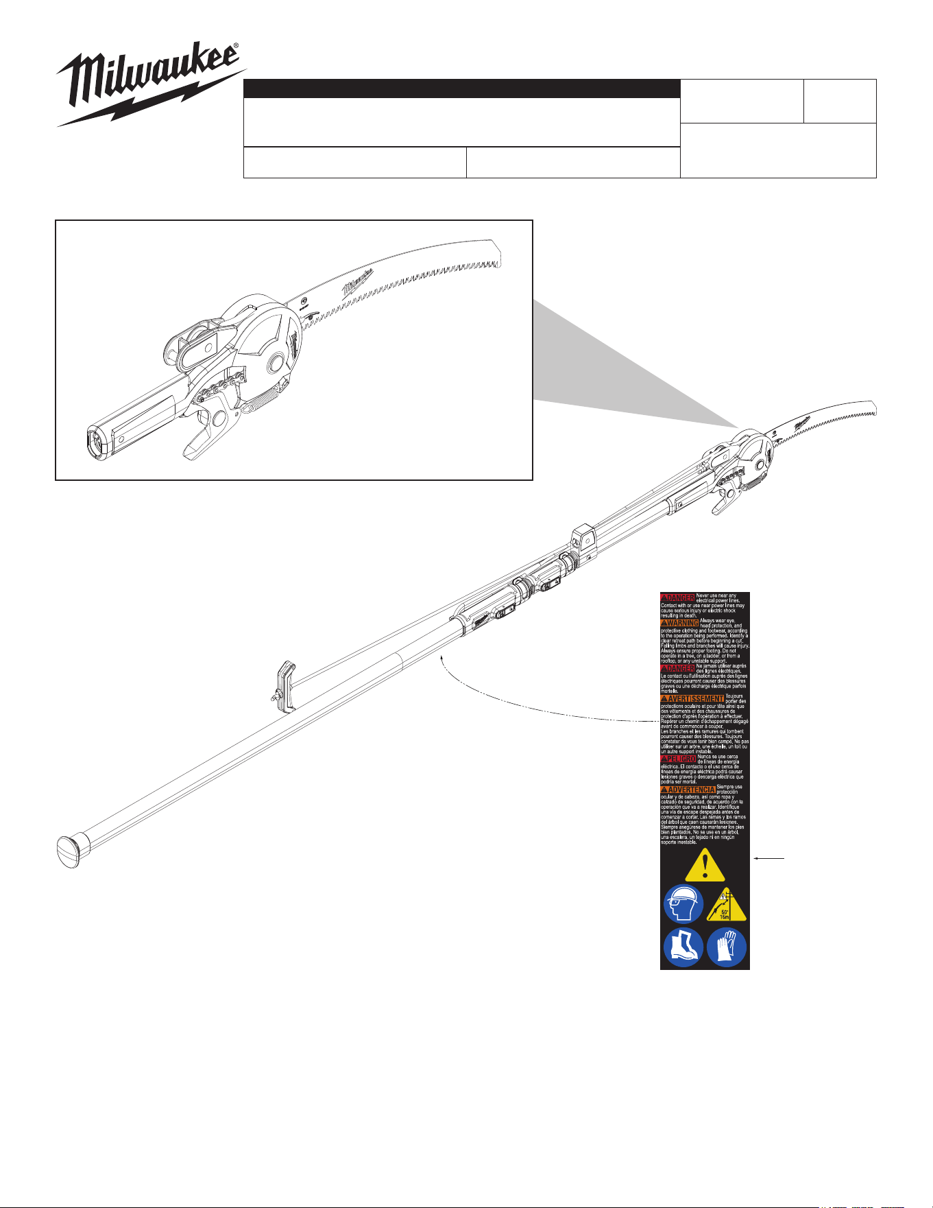
22 10-22-6126 Warning Label (1)
BULLETIN NO.
PN0005474
SERVICE PARTS LIST
REVISED BULLETIN
SPECIFY CATALOG NO. AND SERIAL NO. WHEN ORDERING PARTS
POLE PRUNER & SAW
REPLACEMENT BLADE KIT & HEAD
DATE
Apr. 2025
WIRING INSTRUCTION
CATALOG NO. SERIAL NO.
48-22-9375
FIG. SERVICE NOTES
63
A clean, dry surface is essential for proper performance for
any adhesive system. The area intended for application of any
adhesive label or nameplate must be prepared by cleaning with
isopropyl alcohol. The solvent is to be applied with a clean, lint
free applicator and the surface allowed to dry before applying
the label or nameplate.
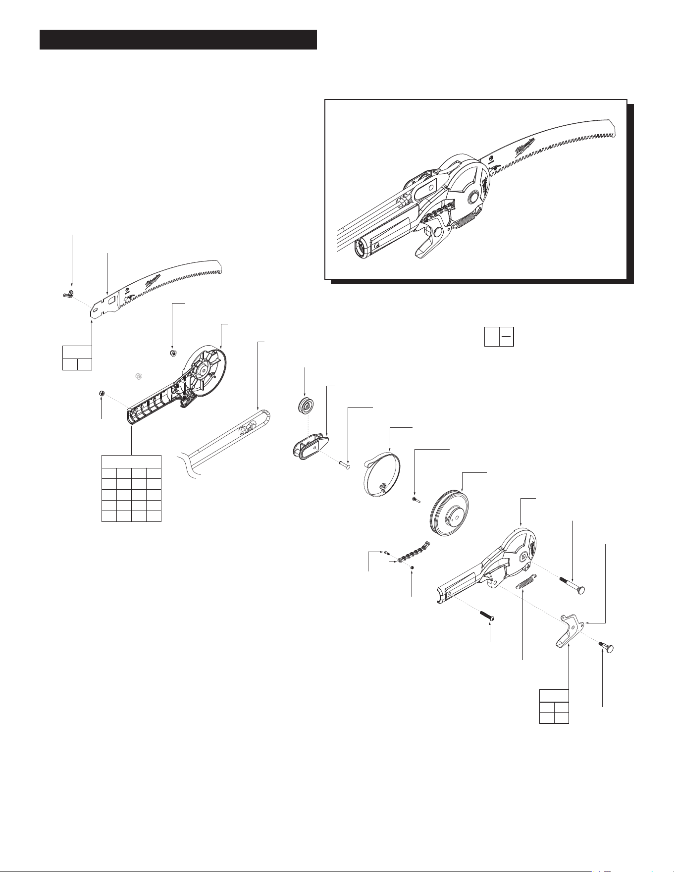
HEAD SUB-ASSEMBLY
- See Page 2
3
2
5
8
1
6
7
13
20
18
19
10
12
11
9
17
15
(2x)
21
16
14
4
1 2 3 4
5 6 7 8
9 10 11 12
13 14 15 16
17 18 19 20
30
2 4
6 7
32
16 21
31
FIG. PART NO. DESCRIPTION OF PART NO. REQ.
1 --------------- Housing Cover (1)
2 --------------- Extension Spring (1)
3 --------------- Pivot Bolt, 1/4-20 Thread (1)
4 --------------- Pruner Blade (1)
5 --------------- Pivot Bolt, 1/4-20 Thread (1)
6 --------------- Pivot Nut, 3MM Thread (1)
7 --------------- Pivot Bolt, 3MM Thread (1)
8 --------------- Bolt, M6 Thread (1)
9 --------------- Rope (1)
10 --------------- Rivet, Hollow-End (1)
11 --------------- Pulley (1)
12 --------------- Floating Pulley Housing (1)
13 --------------- Chain Sub-Assy (1)
14 --------------- Nut (1)
15 --------------- Pivot Nut, 1/4-20 Thread (2)
16 --------------- Wingnut (1)
17 --------------- Housing Support (1)
18 --------------- Pivot Bolt (1)
19 --------------- Strap - Combo Wheel (1)
20 --------------- Combo Wheel (1)
21 --------------- Saw Blade (1)
30 48-22-9385 Pruner Mechanism Assembly (1)
31 48-22-9387 Saw Blade Kit (1)
32 48-22-9386 Pruner Blade Replacement Kit (1)
HEAD SUB-ASSEMBLY
0
00
EXAMPLE:
Component Parts (Small #)
Are Included When Ordering
The Assembly (Large #).
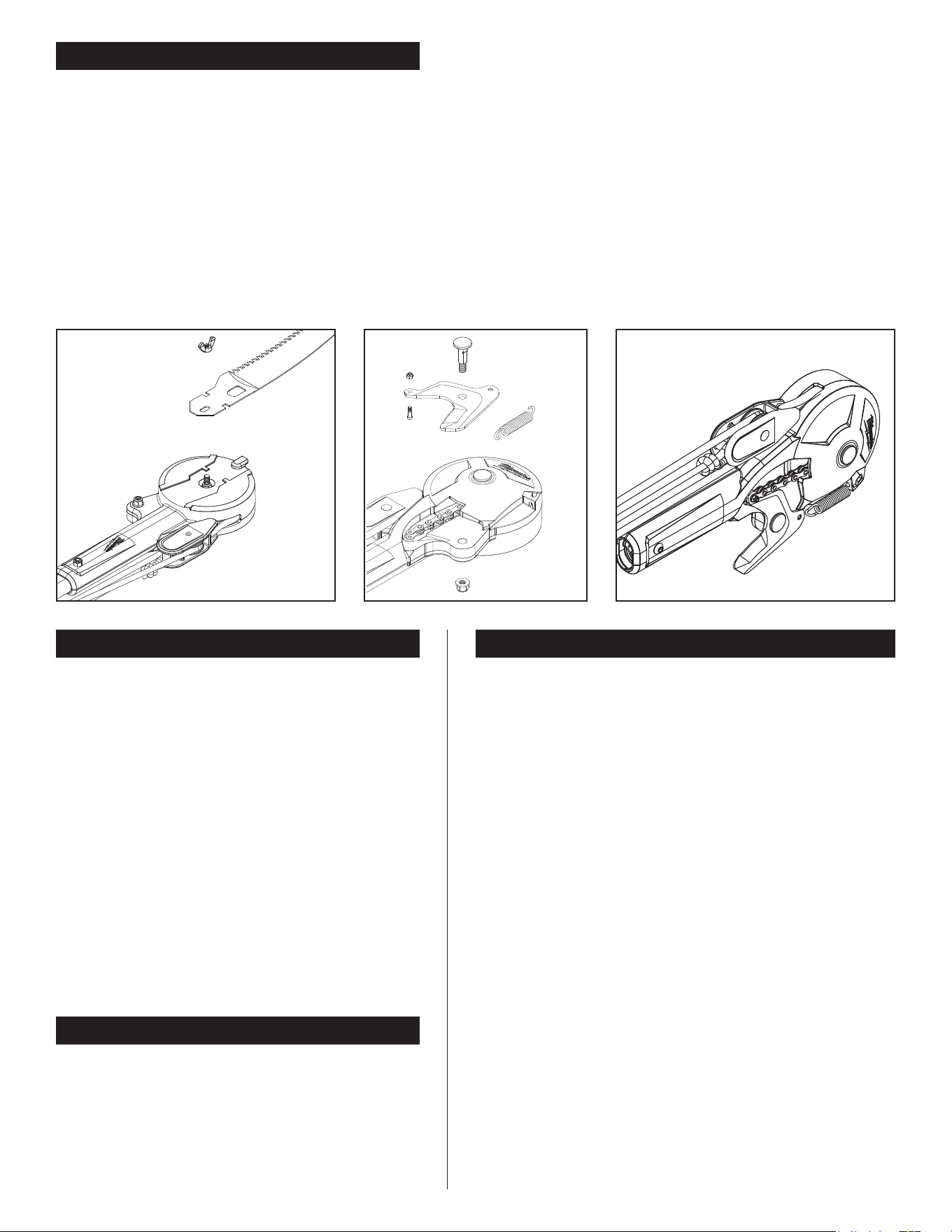
FIG. B
PRUNER BLADE REPLACEMENT
TO REMOVE OLD BLADE:
1. Remove the saw blade (21) and wingnut (16).
FIG A
2. Secure pole into a vise.
NOTE: To prevent tool marring, wrap the tool
with a micro ber before securing into the vice.
3. Remove back bolt (5) using a 10 mm socket.
4. Remove the spring (2).
5. Remove both nut (6) and bolt (7)
on the chain (13). FIG B
NOTE: Clamp chain down to prevent it falling
back into the head.
6. Clean area under the pruning blade (4).
TO ATTACH NEW BLADE:
1. To attach, use the new pruning blade (4) and attach it to the chain (13)
using the new nut (6) and bolt (7). Push bolt (7) though from underneath,
nut (6) on top using a 2 mm hex driver and a 5.5 mm socket.
2. Feed spring (2) into slot on pruning head from the bottom, making sure
the hooks are facing out towards the user.
3. Attach other end of spring to the pruning blade.
4. Put bolt (5) through the pruning blade into the housing (1).
Align the ats so it goes through the pruner head halves.
5. Tighten the nut and bolt to hand tight, then loosen a quarter turn.
6. Pull rope (9) to make sure pruning blade operates accordingly and
returns to the open position.
7. Adjust nut as needed if the pruning blade is too tight or if too loose.
FIG. A
PRUNER HEAD REPLACEMENT
TO REPLACE PRUNER HEAD:
1. Remove the saw blade (21) and wingnut (16). FIG A
2. Undo knot on rope (9) under the shuttle pulley and
unspool the rope.
3. Remove the nut (14) and bolt (8) holding the pruner
head onto the pole using a 10 mm socket and a 4 mm
hex driver.
4. Remove pruner head.
5. Put new pruner head on the pole. Make sure shuttle
side is on pulley housing side.
6. Secure the new pruner head with new nut and bolt until
tight.
7. Undo knot of new rope.
8. Feed rope through the lower pulley and pull back
through to the shuttle (12).
9. Tie rope around the post at the bottom of the shuttle
and make a knot. FIG C
NOTE: Ensure the webbing at the top of the shuttle is
not twisted. The stitch should face down.
FIG. C
OPERATION
ADJUSTING THE TELESCOPING POLE HEIGHT:
1. Unlock the friction clamp and push the spring-loaded button in.
2. While pushing in the button, extend or collapse the pole as
needed. NOTE: Each pole has 3 adjustment holes. Once close
to the desired hole, let go of the button and keep extending/
collapsing the pole until the spring-loaded button clicks into
place.
3. Lock the friction clamp in place. NOTE: Make sure the pole
pieces are secure and not moving before use or storing the tool.
ADJUSTING THE ROPE:
1. For best leverage when using the rope, shift the rope handle
to the desired position on the rope. Run the rope through the
groove provided in the rope handle. The rope will stay in the
groove and not slip when using the pruner.
USING THE ROPE FOR PRUNING:
1. Set the blade on the branch needing to be cut, apply slight
downward pressure on the branch.
2. Pull the rope to start cutting.
EXTENDING AND STORING THE SAW BLADE:
1. Before use, loosen the wingnut until the saw blade can move.
Rotate the saw 180° in the clockwise direction.
2. Lift the saw so the slot ts through the hook on the head.
Tighten the wingnut once the saw is seated in place.
3. Reverse steps 1 and 2 for storing the tool. When storing the
tool, wrap the extra rope around the tabs sticking out of the
pulley housing and large bottom coupler.
PRUNER HEAD REPLACEMENT
Clean dust and debris from any vents. Keep tool clean, dry
and free of oil or grease. Use only mild soap and a damp
cloth to clean, since certain cleaning agents and solvents
are harmful to plastics and other insulated parts. Some
of these include gasoline, turpentine, lacquer thinner,
paint thinner, chlorinated cleaning solvents, ammonia and
household detergents containing ammonia. Never use
ammable or combustible solvents around tools.