
29
(2x)
19
28
(2x)
120
43
204
126
9
(5x)
18
19
115
123
1
(3x)
9
(15x)
17
16
40
39
32
37
21
9
(5x)
113
112
(2x)
29
28
20
31
(4x)
9
(3x)
9 18
19 21
217
37
201
39
40
218
19 28 29
43 120
205
9 16 17 20
112 123 126
203
1 9 16 17 18 19 20 21 28 29 31
32 37 39 40 43 112 113 123 126 204 224
221
1 9
31 32
224
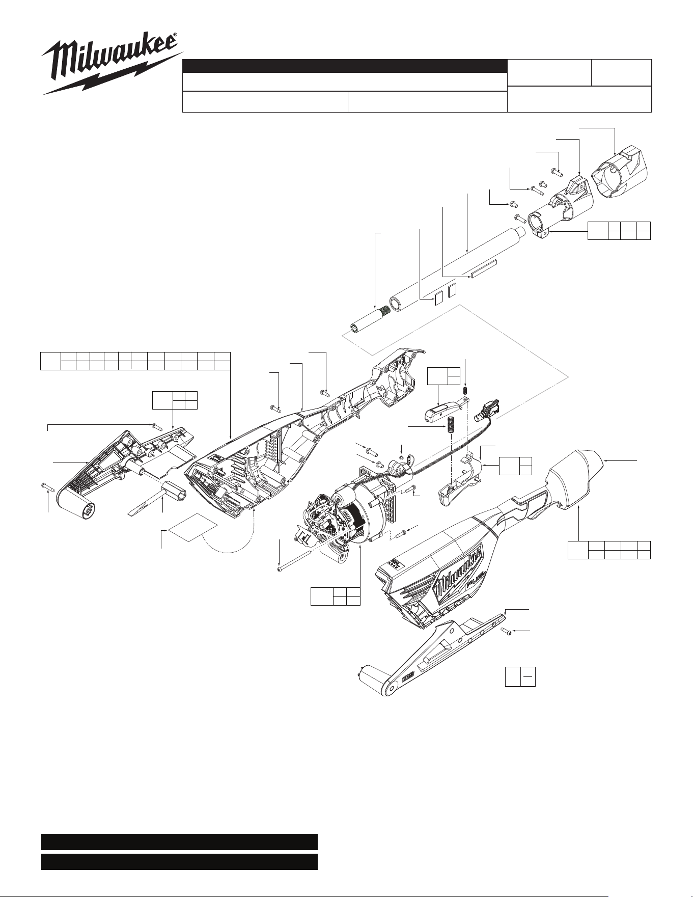
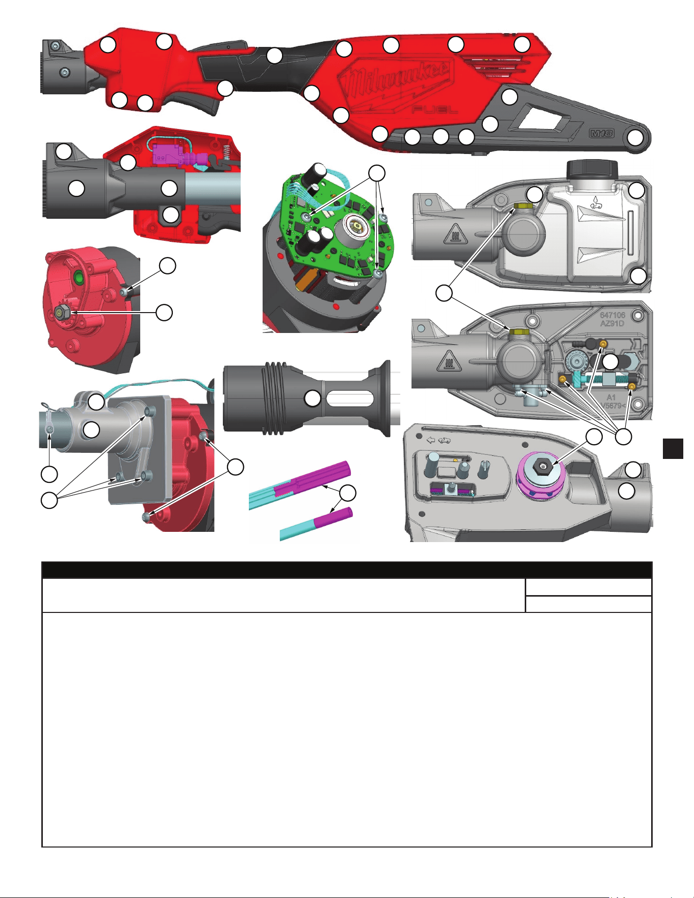
M18 FUEL™ TELESCOPING POLE SAW
3013-20
N26A
54-49-2875
See Page 6 and 7
Jan. 2025
REVISED BULLETIN
BULLETIN NO.
WIRING INSTRUCTION
DATE
SPECIFY CATALOG NO. AND SERIAL NO. WHEN ORDERING PARTS
CATALOG NO.
FIG. PART NO. DESCRIPTION OF PART NO. REQ.
1 05-74-0516 M4 x 67mm Pan Hd. T-20 Machine Screw (3)
9 06-82-4003 M4 x 16mm Pan Hd. T-20 ST Screw (28)
16 --------------- Power Head Housing - Cover (1)
17 05-88-5375 M4 x 13.5mm Pan Hd. T-20 ST Screw (1)
18 --------------- Power Head Guard - Cover (1)
19 05-88-1257 M4 x 22mm Pan Hd. T-20 ST Screw (2)
20 --------------- Power Head Housing - Support (1)
21 --------------- Power Head Guard - Support (1)
28 05-78-0029 M5 x 8mm Pan Hd. T-25 Machine Screw (3)
29 05-74-0315 M5 x 17mm Pan Hd. T-25 Machine Screw (3)
31 06-82-4003 M4 x 16mm Cap Hd. Hex Recess Mach. Sc. (4)
32 05-74-0538 M3 x 3.5mm Pan Hd. Phillips Machine Scr. (1)
37 40-50-0373 Action Lever Spring (1)
39 40-50-0374 Trigger Spring (1)
SCREW TORQUE SPECIFICATIONS ARE ON PAGE 5
FIG. NOTES
123 Prior to taking tool apart, use a sharp razor blade to score the center
line of nameplate. This will allow housing halves (16 and 20) to
separate when housing screws are removed.
123 A clean, dry surface is essential for the proper performance for any
adhesive system. The area intended for application of any adhesive
label or nameplate must be prepared by cleaning with isopropyl
alcohol. The solvent is to be applied with a clean, lint free applicator
and the surface allowed to dry before applying any label or nameplate.
LUBRICATION NOTES ARE ON PAGE 2
SERIAL NO.
SERVICE PARTS LIST
MILWAUKEE TOOL
l
www.milwaukeetool.com
13135 W. LISBON RD., BROOKFIELD, WI 53005
Drwg. 5
40 --------------- Trigger Cap (1)
43 --------------- Tube Coupler (1)
112 44-52-0009 Rubber Foam (2)
113 42-04-0101 Sleeve Adapter (1)
115 45-96-1001 Screwdriver / Wrench (1)
120 45-12-0018 Rubber Boot (1)
123 12-20-0222 Service Nameplate (1)
126 44-52-0004 Rubber Foam (1)
201 31-92-0013 Trigger Lock-Out Service Assembly (1)
203 31-44-0164 Power Head Housing Service Kit (1)
204 45-22-0128 Coupler Tube Service Assembly (1)
205 42-90-0108 Tube Coupler Service Kit (1)
217 43-54-0028 Impact Guard Service Kit (1)
218 31-92-0029 Trigger Service Kit (1)
221 14-38-2219 Power Head Service Assembly (1)
224 14-30-1924 Motor and Gearcase Assembly (1)
FIG. PART NO. DESCRIPTION OF PART NO. REQ.
EXAMPLE:
Component Parts (Small #)
Are Included When Ordering
The Assembly (Large #).
0
00
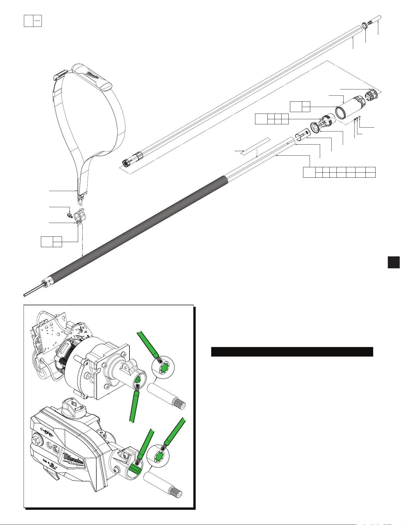
FIG. PART NO. DESCRIPTION OF PART NO. REQ.
44 --------------- Outer Tube Assembly (1)
45 --------------- Bushing (1)
46 --------------- Screw Sleeve (2)
47 --------------- Washer (2)
48 05-78-0038 M4 x 7mm Pan Hd. T-20 Machine Screw (2)
49 --------------- Female Collar (1)
50 --------------- Collet (1)
60 --------------- Inner Tube (1)
91 --------------- Male Collar (1)
113 42-04-0101 Sleeve Adapter (2)
114 31-86-0014 Spacer (1)
116 --------------- Knob (1)
117 --------------- Harness Hook (1)
118 45-56-0034 Shoulder Strap (1)
120 45-12-0018 Rubber Boot (Not Shown) (1)
124 10-20-0054 Warning Label (1)
206 42-76-0097 Male Collar / Bushing Service Kit (1)
207 42-76-0099 Female Collar / Collet Service Assembly (1)
208 42-82-0013 Extension Tube Service Assembly (1)
209 43-75-0028 Harness Hook Service Assembly with Knob (1)
0
00
EXAMPLE:
Component Parts (Small #) Are Included
When Ordering The Assembly (Large #).
48
(2x)
47
(2x)
46
(2x)
91
45
44
113
114
60
50
49
118
116
117
124
45 46 47
48 91
206
49
50
207
44 45 46 47 48 49
50 60 91 113 114 120 124
208
116
117
209
NOTE: Rubber Boot (120)
is illustrated on page one.
SCREW TORQUE SPECIFICATIONS ARE ON PAGE 5
FIG. NOTES
124 A clean, dry surface is essential for the proper performance for
any adhesive system. The area intended for application of any
adhesive label or nameplate must be prepared by cleaning with
isopropyl alcohol. The solvent is to be applied with a clean, lint
free applicator and the surface allowed to dry before applying
any label or nameplate.
Electronics and
Armature/Gearcase Assemblies
See page 1
Cutter Head Gearcase
and Oil Tank Assemblies
See page 3
LUBRICATION
Type 'J' Grease, 49-08-4220 (1 lb. can)
When servicing, remove 90-95% of the existing grease prior to
installing Type 'J'. Original grease may be similar in color but not
compatible with 'J'.
Regarding parts to be lubricated:
Apply a light coating of grease to all highlighted parts shown prior to
installation.
2
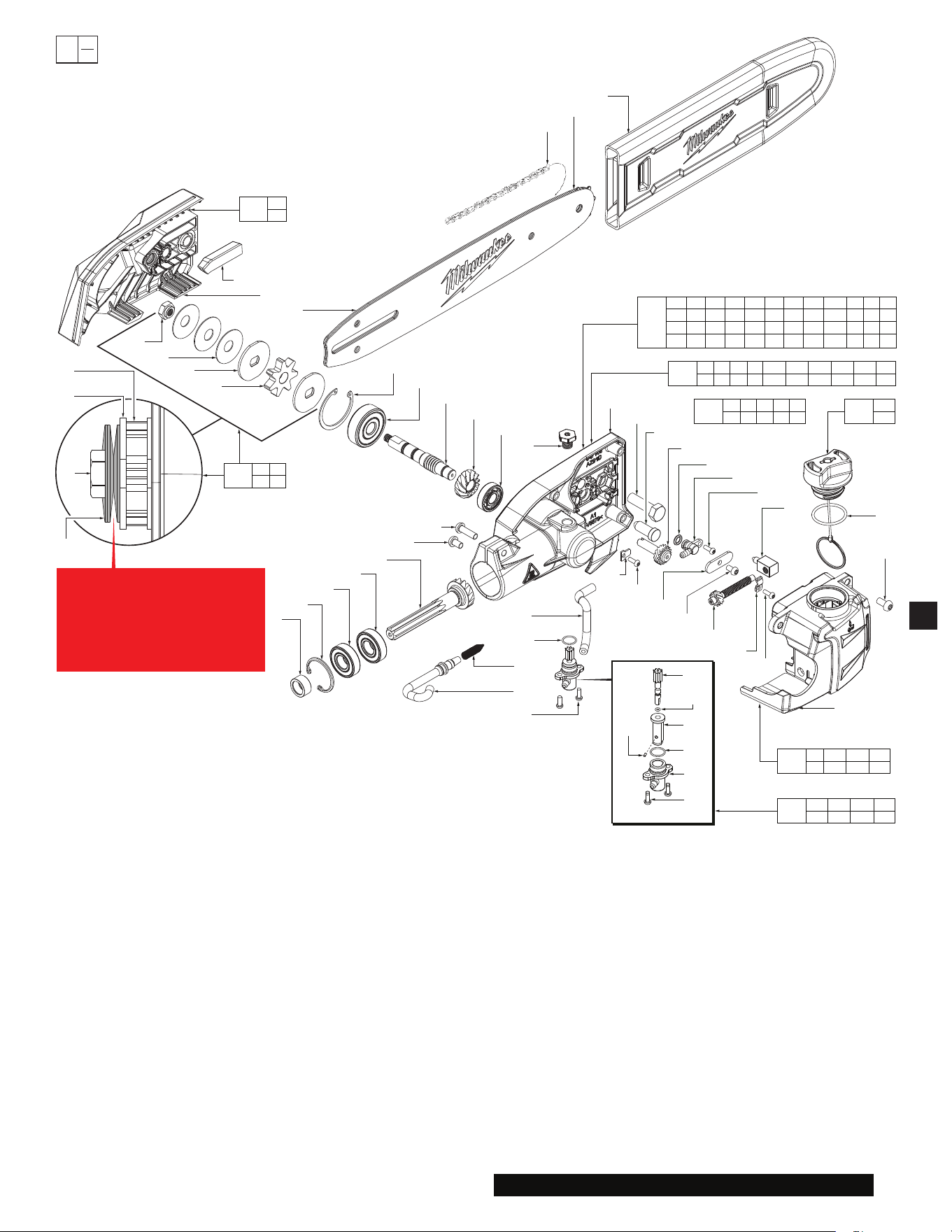
FIG. NOTES
124 A clean, dry surface is essential for the proper performance for
any adhesive system. The area intended for application of any
adhesive label or nameplate must be prepared by cleaning with
isopropyl alcohol. The solvent is to be applied with a clean, lint
free applicator and the surface allowed to dry before applying
any label or nameplate.
0
00
EXAMPLE:
Component Parts (Small #) Are Included
When Ordering The Assembly (Large #).
FIG. PART NO. DESCRIPTION OF PART NO. REQ.
28 05-78-0029 M5 x 8mm Pan Hd. T-25 Machine Screw (1)
29 05-74-0315 M5 x 17mm Pan Hd. T-25 Machine Screw (1)
48 05-78-0038 M4 x 7mm Pan Hd. T-20 Machine Screw (1)
55 --------------- Ball Bearing (1)
FIG. PART NO. DESCRIPTION OF PART NO. REQ.
64 --------------- Sprocket Cover w/Self Contained Flange Nut (1)
65 --------------- Insert Block (1)
66 --------------- Shaft Nut (1)
67 --------------- Spring Washer (3)
68 --------------- Sprocket Washer (2)
69 --------------- Sprocket (1)
70 --------------- Bevel Retaining Ring (1)
71 --------------- Ball Bearing (1)
72 --------------- Input Shaft (1)
73 --------------- Bevel Gear (1)
74 --------------- Ball Bearing (1)
75 --------------- Bevel Pinion (1)
76 --------------- Ball Bearing (1)
77 05-85-0080 M8 x 1.25 Hex Hd. T-25 Machine Screw (1)
78 --------------- Bevel C-Ring (1)
79 --------------- Stopper Bushing (1)
80 --------------- Cutter Head Gearcase (1)
81 49-16-2759 10" Chain, 3/8" Pitch (Accessory) (1)
82 49-16-2760 10" Chain Bar (Accessory) (1)
83 49-62-0012 Scabbard for 10" Bar (Accessory) (1)
84 --------------- Chain Tensioner Adjustment Screw (1)
85 --------------- Tensioning Main Screw (1)
86 --------------- Chain Tension Post (1)
87 --------------- Tensioning Rack Retention Tab (1)
88 --------------- Location Pin (1)
89 05-85-0012 M8 x 28mm Hex Hd. Machine Screw (1)
90 --------------- Stamping Plate (1)
92 --------------- Oil Tank (1)
93 05-78-0024 M5 x 10mm Pan Hd. T-25 Machine Screw (3)
94 --------------- Oil Pump Housing (1)
95 --------------- Outlet Tube (1)
FIG. PART NO. DESCRIPTION OF PART NO. REQ.
96 --------------- Connector (1)
97 34-40-4002 O-Ring (1)
98 05-81-0015 M3 x 8.5mm Pan Hd. T-10 Machine Screw (5)
99 --------------- Tensioning Rack Retension Tab (1)
100 --------------- Pump Gear (1)
101 --------------- Pump Body Pin (1)
102 --------------- Pump Gear O-Ring (1)
103 --------------- Pump Body (1)
104 --------------- Pump Housing O-Ring (1)
105 --------------- Inlet Tube (1)
106 --------------- Cone Spring (1)
108 34-40-0228 Oil Cap O-Ring (1)
119 14-30-0071 Cutter Head Gearcase Assembly (1)
210 42-52-0051 Oil Cap Assembly (1)
211 45-44-0019 Sprocket Cover Service Kit (1)
212 32-10-0023 Sprocket Clutch Service Kit (1)
213 42-54-0014 Oil Pump Service Assembly (1)
214 45-66-0021 Oil Tank Service Kit (1)
215 42-60-0031 Chain Tensioning Service Kit (1)
220 14-38-0063 Cutting Head Service Assembly (1)
69
68
(2x)
67
(3x)
66
It is critical to orient the three
disc springs as shown.
As an aid for assembly, refer to
page 4 for detailed instructions
regarding the installation of the
Sprocket Clutch Service Kit #212.
100
102
103
104
94
98
(2x)
101
66
67
(3x)
68
(2x)
69
65
64
82
70
71
72
73
74
77
80
89
88
84
97
96
98
86
98
87
85
48
90
98
99
108
93
(3x)
92
79
78
55
76
75
28
29
95
104
106
105
98
(2x)
81
82
83
64
65
211
66 67
68 69
212
108
210
94 98 100 101
102 103 104
213
92 93 95 96
97 105 106
214
48 84 85 86 87
88 89 90 98 99
215
55 70 71 72 73 74 75 76 77 78
79 80 94 98 100 101 102 103 104
119
28 29 48 55 64 65 66 67 68 69 70 71
72 73 74 75 76 77 78 79 80 84 85 86
87 88 89 90 92 93 94 95 96 97 98 99
100101102103104105106108 210
220
SCREW TORQUE SPECIFICATIONS ARE ON PAGE 5
FIG. NOTES
94 As an aid to installing Inlet Tube (105)
and Outlet Tube (95) onto Oil Pump
Housing add a little chain oil to nipples
of Oil Pump Housing prior to installation.
3
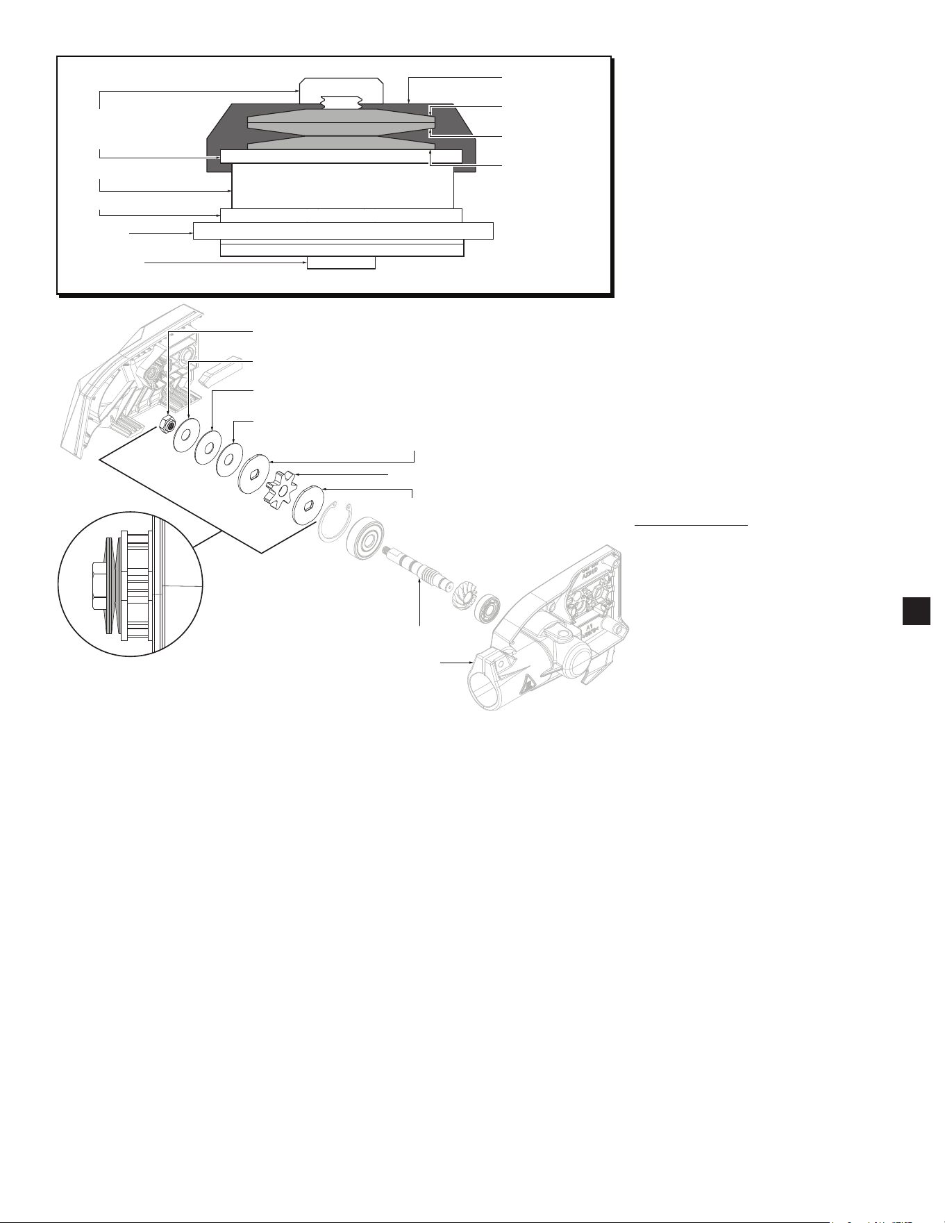
Plastic Guide
Spring Washer 3
Spring Washer 2
Spring Washer 1
Sprocket Nut
Sprocket Washer 2
Sprocket
Sprocket Washer 1
Gearcase
Output Shaft
INSTALLING THE
SPROCKET CLUTCH SERVICE KIT
There are a series of 3 Spring Washers that must
be oriented in a specic way for the tool to func-
tion properly.
1. WARNING! Remove battery to avoid starting
the tool.
2. Install Sprocket Washer 1 onto Output Shaft,
ensure it is seated on the shoulder of the
Output Shaft.
3. Install Sprocket onto Output Shaft, ensure it is
seated on Sprocket Washer 1.
4. Install the Sprocket Washer 2, ensure it is
seated on the Sprocket.
5. Install Plastic Guide onto second Sprocket
Washer.
6. Install the 3 Spring Washers in the correct
orientation, as shown in detail on the left.
The Plastic Guide will help ensure the Spring
Washers are aligned properly.
7. Fasten the Sprocket Nut to the threads on the
end of the Output Shaft. Tighten to 7 ft-lbs.
with a calibrated device.
8. Remove and discard Plastic Guide.
Output Shaft
Gearcase
Sprocket Nut
Spring Washer 3
Spring Washer 2
Spring Washer 1
Sprocket Washer 2
Sprocket
Sprocket Washer 1
INSTALLATION OF #212, 32-10-0023 SPROCKET CLUTCH SERVICE KIT
4
SCREW TORQUE SPECIFICATIONS
SEAT TORQUE
FIG. PART NO. DESCRIPTION OF FASTENER WHERE USED (kgf-cm) (lb-in)
1 05-74-0193 M4 x 67mm Pan Hd. T-20 Machine Screw Electronics Service Assembly 25±3 21.6±2.6
9a 06-82-4003 M4 x 16mm Pan Hd. T-20 ST Screw Power Head Housing & Power Head Guard 14±2 12.1±1.7
9b 06-82-4003 M4 x 16mm Pan Hd. T-20 ST Screw Motor Housing 14±2 12.1±1.7
17 05-88-5375 M4 x 13.5mm Pan Hd. T-20 ST Screw Power Head Housing 14±2 12.1±1.7
19a 05-88-1257 M4 x 22mm Pan Hd. T-20 ST Screw Power Head Guard 16±2 13.8±1.7
19b 05-88-1257 M4 x 22mm Pan Hd. T-20 ST Screw Tube Coupler 14±2 12.1±1.7
28a 05-78-0029 M5 x 8mm Pan Hd. T-25 Machine Screw Tube Coupler & Armature/Gearcase Service Assy. 35±3 30.3±2.6
28b 05-78-0029 M5 x 8mm Pan Hd. T-25 Machine Screw Tube Coupler & Cutter Head Gearcase 50±3 43.3±2.6
29a 05-74-0315 M5 x 17mm Pan Hd. T-25 Machine Screw Tube Coupler & Armature/Gearcase Service Assy. 35±3 30.3±2.6
29b 05-74-0315 M5 x 17mm Pan Hd. T-25 Machine Screw Tube Coupler & Cutter Head Gearcase 50±3 43.3±2.6
31 06-82-4003 M4 x 16mm Cap Hd. Hex Recess Mach. Screw Armature/Gearcase Service Assembly 20±2 17.3±1.7
32 05-74-0538 M3 x 3.5mm Pan Hd. Phillips Machine Scr. Ground Wire Terminal 5.5±0.5 4.7±0.4
48 05-78-0038 M4 x 7mm Pan Hd. T-20 Machine Screw Male Collar & Stamping Plate 18±2 15.6±1.7
-- --------------- Self Contained M8 Flange Nut (See page 3) Sprocket Cover 140±10 121±8.6
66 --------------- Shaft Nut Input Shaft 95±5 82.4±4.3
77 05-85-0080 M8 x 1.25 Hex Hd. T-25 Machine Screw Cutter Head Gearcase 45±3 39±2.6
93 05-78-0024 M5 x 10mm Pan Hd. T-25 Machine Screw Oil Tank 17±2 14.7±1.7
98 05-81-0015 M3 x 8.5mm Pan Hd. T-10 Machine Screw Oil Pump Housing/Tensioning Rack Retension Tabs 5±0.5 4.3±0.4
98 05-81-0015 M3 x 8.5mm Pan Hd. T-10 Machine Screw Connector 5±0.5 4.3±0.4
113 42-04-0101 Sleeve Adapter Coupler Tube & Inner Tube 33±3 285.6±2.6
113
1
(2x)
17
9b
(3x)
19a
19b
9a
9a
9a
9a
9a
9a
9a
9a
9a
9a
9a
9a
9a 9a
9a
9a
9a
29b
29b
29a
29a
32
28b
28b
93
93
93
48
66
77
98
48
28a
28a
31
14
9b
5
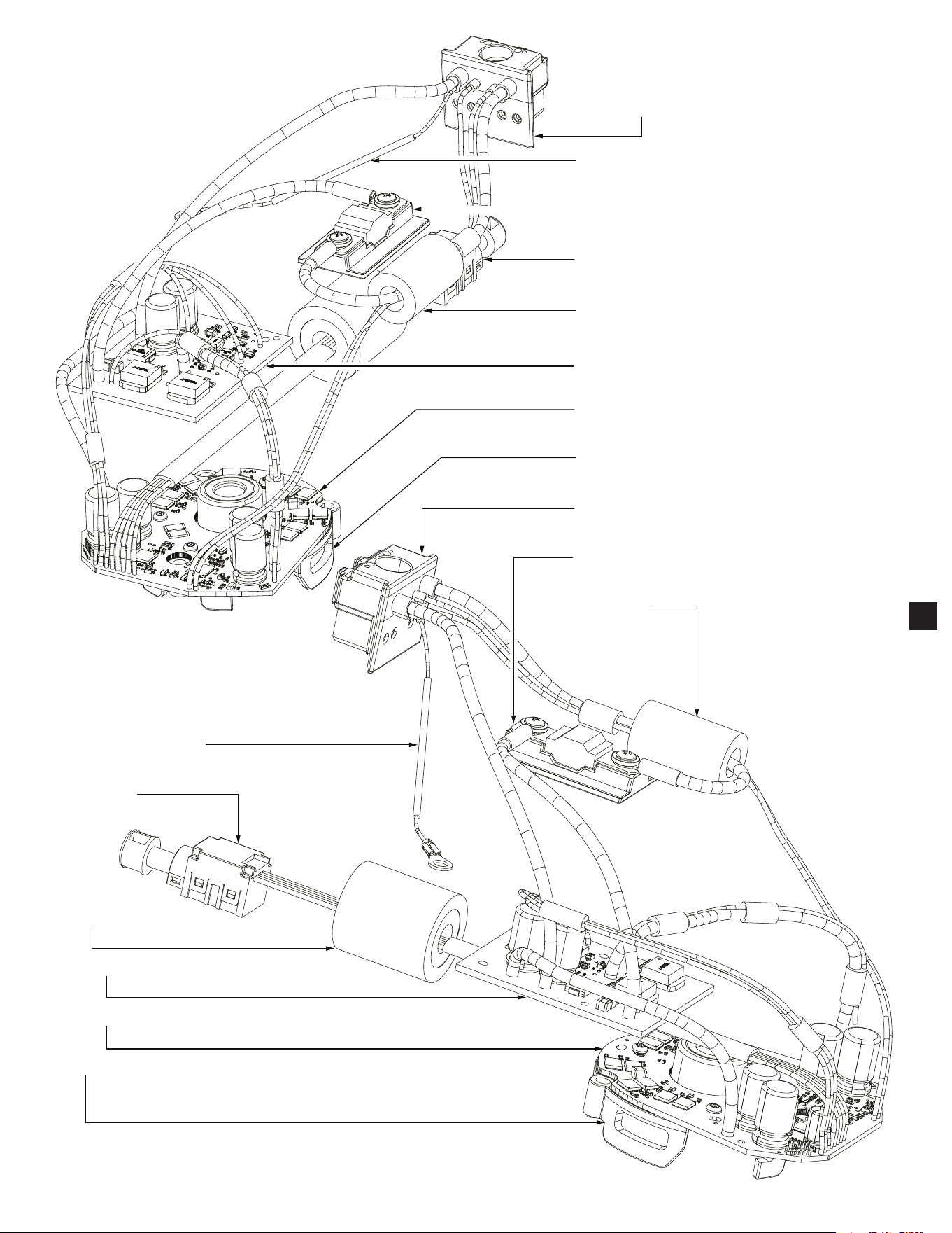
Battery Connector Block
Ground Wire and Terminal
Fuse Assembly
On-Off Switch
Ferrite Bead
SSD Board Assembly
Control Board Assembly
Heat Sink
Battery Connector Block
Fuse Assembly
Ferrite Bead
Ground Wire and Terminal
On-Off Switch
Ferrite Bead
SSD Board Assembly
Control Board Assembly
Heat Sink
Electronic Assembly
shown without Stator
Assembly attached
Electronic Assembly
shown without Stator
Assembly attached
6
21
3
4
5
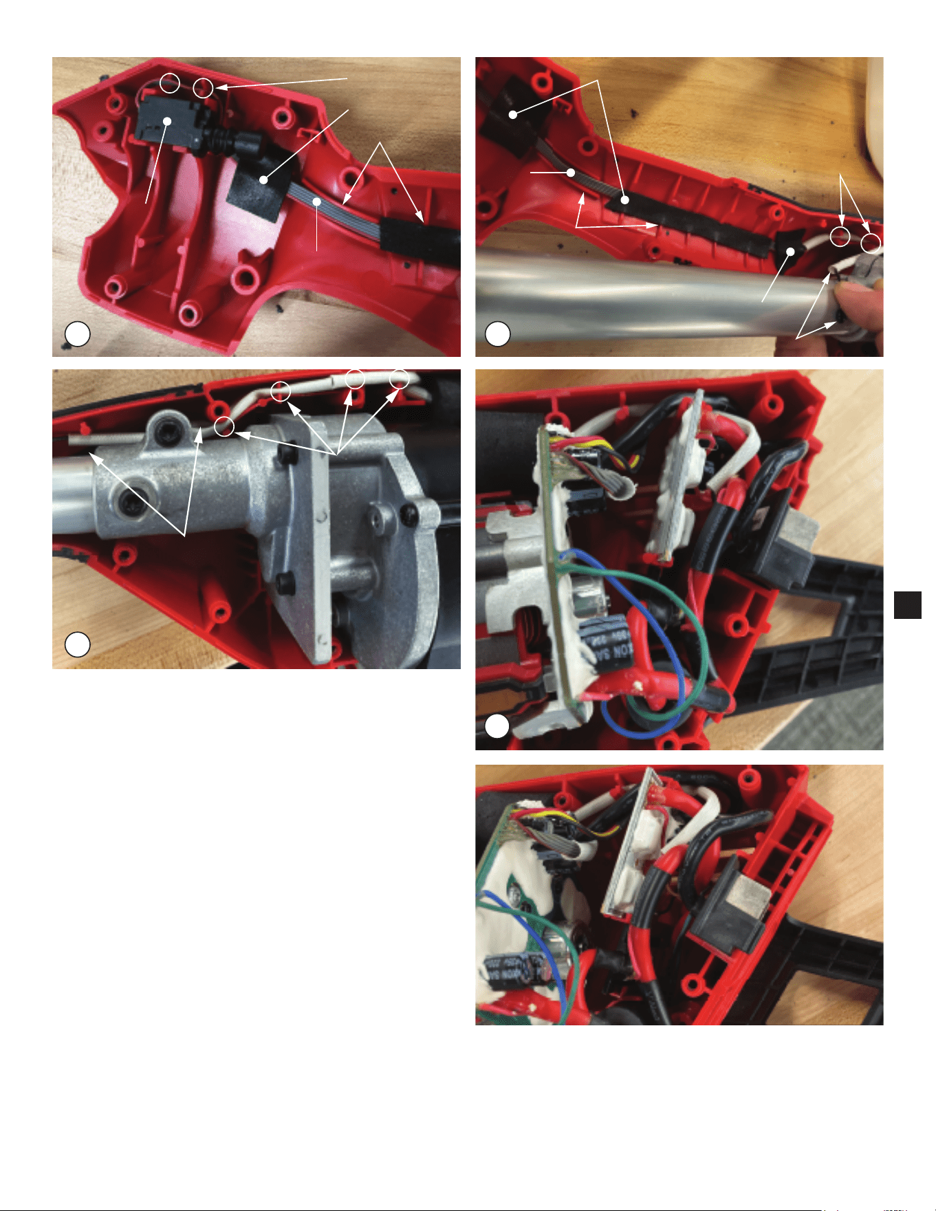
Wire Traps
Foam Tape
Cable Channel
On-Off
Trigger
Switch
Trigger
Ribbon Cable
Cable Channels
Foam Tape
Wire Traps
Foam Tape
Trigger
Ribbon Cable
Ground Wire
Wire Traps
Ground Wire
behind Gearcase
Assembly
1. Route Trigger Switch wires in wire traps as shown. Be sure to push
wires completly down in traps. Place trigger ribbon cable in cable
channel and secure with foam tape. Install Trigger Switch rmly and
squarely in switch cavity of the Power Head Housing Support.
2. Prior to installing the Electronics and Gearcase Assemblies, continue
to route trigger ribbon cable through cable channels of Power Head
Housing Support. Be sure the ribbon cable is pressed at in channel,
(Not lifting onto ribbed sur faces causing wire pinching). Secure the
trigger ribbon cable with foam tape as shown.
3. Place Electronics and Gearcase Assemblies into Housing Support.
Route Trigger Ribbon and Ground Wire through the wire traps shown,
being sure wires are fully seated in wire traps and are not falling out.
4,5 Photos depict components of the electronics package (See page 5).
Install all components rmly and squarely in corresponding cavities of
the Power Head Housing Support. Route all wires as shown being
sure those placed in wire traps are pressed completly down in bottom
of traps. Tuck all excess wires down into handle cavities to avoid
pinching when the Power Head Housing Cover is installed.
As an aid to reassembly, take notice of wire routings and position in
wire guides and traps while dismantling tool.
Be sure that all components of the electronics assembly are seated
rmly and squarely in housing recesses.
Avoid pinched wires, be sure that all wires and sleeves are pressed completely down in wire traps.
Prior to securing housing cover onto the housing support, be sure that there are no interferences.
Before installing the battery, check for proper functionality of shuttles, buttons and triggers.
Install battery and depress switch trigger to assure tool is operating properly.
7