
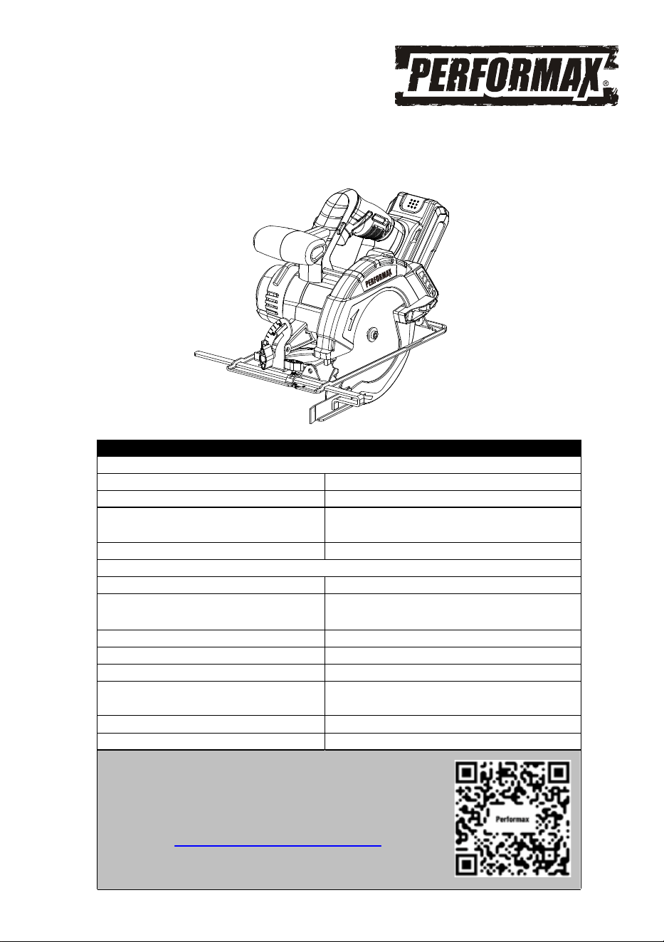
20 VOLT LITHIUM ION CIRCULAR SAW
241-9047
Owner’s Manual
PRODUCT SPECIFICATIONS
CIRCULAR SAW
Speed: 4000 RPM (no load)
Blade: 6 1/2", 5/8" arbor, 24 carbide teeth
Maximum cutting depth: 2 1/8" at 90°
1 9/16" at 45°
Bevel gauge: 0–50°
BATTERY & CHARGER
Battery: 20 V, Lithium ion
Charge time: Approx. 100 minutes for 2Ah battery
and 200 minutes for 4Ah battery
Charger input: 100–240V AC, 50–60 Hz
Charger output: 21.5 V DC, 1.5 A
Weight: 6.03 lbs with battery
Need Assistance?
• Technical questions
• Replacement parts
• Parts missing from package
Email us at:
Call us on our toll-free customer support line:1-866-349-8665
(9-5pm Monday-Friday EST)
Replacement battery:
Replacement charger:
Replacement battery&charger kit:
236-9049, 236-9050, 267-3206,
267-3207
236-9051, 267-3002, 267-3205
241-9040
Scan here for support

2
Product specifications ………….……………………………………………………. 1
Table of contents ……………………………………………………………………... 2
General safety warnings …………………………………………………………….. 3–4
Eye, ear & lung protection …………………………………………………………… 3–4
Electrical safety ………………………………………………………………………. 4
Power tool safety ……………………………………………………………………... 5–6
General safety rules ………………………………………………………………….. 5
Work area ………………………………………………………………….………….. 5
Electrical safety ………………………………………………………………………. 5
Personal safety ……………………………………………………………………….. 5–6
Power tool use and care .……………………………………………………………. 6
Battery tool use and care ……………………………………………………………. 6
Service ………………………………………………………………………………… 6
Specific safety rules ………………………………………………………………….. 7-9
Battery & charger safety ………………………………………………………….…. 10
Battery pack recycling ……………………………………………………………….. 10
Symbols ……………………………………………………………………………….. 11
Know your circular saw …………………………………………………… 12
Assembly and operating …………………………………………………………….. 13–18
Charging the battery pack …………………………………………………………… 13-14
Installing a blade ……………………………………………………… 14-15
Bevel cutting ………………………………………………………………... 15
Adjusting the cutting depth…………………………………………………………... 15
Setting the 0° stop………..………………………………………………….............. 15-16
Installing the edge guide ………………………………………………………........ 16
Safety lock-out switch ………………………………………………....................... 16
ON/OFF trigger switch …………………………………………....................... 17
Installing the dust and vacuum adapters ……………………....................... 1
7
Materials you can cut …………………………………………....................... 17
General cutting ………………………………………………....................... 17-18
Rip guide cutting ………………………………………………....................... 18
Maintenance …………………………………………………………………………... 19
Exploded view ………………………………………………………………………… 20
Parts list ……………………………………………………………………………….. 21-22
Warranty ……………………………………………………………………….……… 23
TABLE OF CONTENTS
3
EYE, EAR & LUNG PROTECTION
This instruction manual includes the following:
General Safety Warnings
Specific Safety Rules and Symbols
Functional Description
Assembly
Operation
Maintenance
!
ALWAYS WEAR EYE PROTECTION THAT CONFORMS WITH CSA
REQUIREMENTS or ANSI SAFETY STANDARD Z87.1
FLYING DEBRIS can cause permanent eye damage. Prescription
eyeglasses ARE NOT a replacement for proper eye protection.
WARNING: Non-compliant eyewear can cause serious injury if
broken during the operation of a power tool.
WARNING: Use hearing protection, particularly during extended
periods of operation of the tool, or if the operation is noisy.
!
GENERAL SAFETY WARNINGS
WARNING: Before using this tool or any of its accessories, read this
manual and follow all Safety Rules and Operating Instructions. The important
precautions, safeguards and instructions appearing in this manual are not
meant to cover all possible situations. It must be understood that common
sense and caution are factors which cannot be built into the product.
!
SAVE THESE INSTRUCTIONS FOR REFERENCE
4
ELECTRICAL SAFETY
GENERAL SAFETY WARNINGS
WEAR A DUST MASK THAT IS DESIGNED TO BE USED WHEN
OPERATING A POWER TOOL IN A DUSTY ENVIRONMENT.
WARNING: Dust that is created by power sanding, sawing, grinding,
drilling, and other construction activities may contain chemicals that are
known to cause cancer, birth defects, or other genetic abnormalities. These
chemicals include:
Lead from lead-based paints
Crystalline silica from bricks, cement, and other masonry products
Arsenic and chromium from chemically treated lumber
The level of risk from exposure to these chemicals varies, according to how
often this type of work is performed. In order to reduce exposure to these
chemicals, work in a we
ll-ventilated area, and use approved safety
equipment, such as a dust mask that is specifically designed to filter out
microscopic particles.
!
WARNING: To avoid electrical hazards, fire hazards or damage to the
tool, use proper circuit protection.
This tool charger is wired at the factory for 120 V AC operation. It must be
connected to a 120 V AC, 15 A circuit that is protected by a time-delayed
fuse or circuit breaker. To avoid shock or fire, replace power cord
immediately if it is worn, cut or damaged in any way.
SAVE THESE INSTRUCTIONS FOR REFERENCE

5
WARNING: Read all safety warnings
and instructions. Failure to follow the warnings
and instructions may result in electric shock, fire
and/or serious injury.
Save all warnings and instructions for future
reference.
Work area safety
Keep work area clean and well lit. Cluttered or
dark areas invite accidents.
Do not operate power tools in explosive
atmospheres, such as in the presence of
flammable liquids, gases or dust. Power tools
create sparks which may ignite the dust or
fumes.
Keep children and bystanders away while
operating a power tool. Distractions can cause
you to lose control.
Electrical safety
Power tool plugs must match the outlet.
Never modify the plug in any way. Do not
use any adap
ter plugs with earthed
(grounded) power tools. Unmodified plugs and
matching outlets will reduce risk of electric
shock.
Avoid body contact with earthed or
grounded surfaces such as pipes, radiators,
ranges and refrigerators. There is an increased
risk of electric shock if your body is earthed or
grounded.
Do not expose power tools to rain or wet
conditions. Water entering a power tool will
increase the risk of electric shock.
Do not abuse the cord. Never use the cord
for carrying, pulling or unplugging the power
tool. Keep cord away from heat, oil, sharp
edges or moving parts. Damaged or
entangled cords increase the risk of electric
shock.
When operating a power tool outdoors, use
an extension cord suitable fo
r outdoor use.
Use of a cord suitable for outdoor use reduces
the risk of electric shock.
If operating a power tool in a damp location
is unavoidable, use a residual current device
(RCD) protected supply. Use of a ground fault
circuit interrupter (GFCI) reduces the risk of
electric shock.
Personal safety
Stay alert, watch what you are doing and use
common sense when operating a power tool.
Do not use a power tool while you are tired
or under the influence of drugs, alcohol or
medication. A moment of inattention while
operating power tools may result in serious
personal injury.
Use personal protective equipment. Always
wear eye protection. Protective equipment
such as dust mask, non-skid safety shoes, hard
hat, or hearing protection used for appropriate
conditions will reduce personal injuries.
Prevent unintentional starting. Ensure the
switch is in the off-position before
connecting to power source and/or battery
pack, picking up or carrying the tool.
Carrying power tools with your finger on the
switch or energizing power tools that have the
switch on invites accidents.
Remove any adjusting key or wrench before
turning the power tool on. A wrench or a key
left attached to a rotating part of the power tool
may result in personal injury.
Do not overreach. Keep proper footing and
balance at all times. This enables better
control of the power tool in unexpected
situations.
Dress properly. Do not wear loose clothing
or jewelry. Kee
p your hair, clothing and
gloves away from moving parts. Loose
clothes, jewelry or long hair can be caught in
moving parts.
Do not let familiarity gained from frequent use
of tools allow you to become complacent and
ignore tool safety principles. A careless action
can cause severe injury within a fraction of a
second.
If devices are provided for the connection of
dust extraction and collection facilities,
ensure these are connected and properly
used. Use of dust collection can reduce dust
related hazards.
POWER TOOL SAFETY
!

Keep handles and grasping surfaces dry,
clean and free from oil and grease. Slippery
handles and grasping surfaces do not allow for
safe handling and control of the tool in unexpect-
ed situations.
Do not use a battery pack or tool that is
damaged or modified. Damaged or modified
batteries may exhibit unpredictable behavior
resulting in fire, explosion or risk of injury.
Do not expose a battery pack or tool to fire or
excessive temperature. Exposure to fire or
temperature above 113°F (45°C) may cause
explosion.
Follow all charging instructions and do not
charge the battery pack or tool outside the
temperature range specified in the instruc-
tions. Charging improperly or at temperatures
outside the specified range may damage the
battery and increase the risk of fire.
6
PERSONAL SAFETY – cont’d
Power tool use and care
Do not force the power tool. Use the correct
power tool for your application. The correct
power tool will do the job better and safer at the
rate for which it was designed.
Do not use the power tool if the switch does
not turn it on and off. Any power tool that
cannot be controlled with the switch is
dangerous and must be repaired.
Disconnect the plug from the power source
and/or the battery pack from the power tool
before making any adjustments, changing
accessories, or storing power tools. Such
preventive safety measures reduce the risk of
starting the power tool accidentally.
Store idle power tools out of the reach of
children and do not allow persons u
nfamiliar
with the power tool or these instructions to
operate the power tool. Power tools are
dangerous in the hands of untrained users.
Maintain power tools. Check for
misalignment or binding of moving parts,
breakage of parts and any other condition
that may affect the power tool’s operation. If
damaged, have the power tool repaired
before use. Many accidents are caused by
poorly maintained power tools.
Keep cutting tools sharp and clean. Properly
maintained cutting tools with sharp cutting
edges are less likely to bind and are easier to
control.
Use the power tool, accessories and tool bits
etc. in accordance with these instructions,
taking into account the working conditions
and the work to be performed. Use of the
power tool for operations different from those
intended could resu
lt in a hazardous situation.
Hold power tool by insulated gripping
surfaces, because the blade may contact its
own cord. Cutting a "live" wire may make
exposed metal parts of the tool "live" and could
give the operator an electric shock.
Battery tool use and care
Recharge only with the charger specified by
the manufacturer. A charger that is suitable for
one type of battery pack may create a risk of fire
when used with another battery pack.
Use power tools only with specifically
designated battery packs. Use of any other
battery packs may create a risk of injury and
fire.
When battery pack is not in use, keep it away
from other metal objects, like paper clips,
coins, keys, nails, screws or other small
metal objects that can make a connection
fro
m one terminal to another. Shorting the
battery terminals together may cause burns or a
fire.
Under abusive conditions, liquid may be
ejected from the battery; avoid contact. If
contact accidentally occurs, flush with water.
If liquid contacts eyes, additionally seek
medical help. Liquid ejected from the battery
may cause irritation or burns.
Service
Have your power tool serviced by a qualified
Never service damaged battery packs.
Service of battery packs should only be
performed by the manufacturer or authorized
service providers.
repair person using only identical
replacement parts. This will ensure that the
safety of the power tool is maintained.
POWER TOOL SAFETY

7
WARNING: Know your cordless
circular saw. Do not plug in the charger or
install the battery in the tool until you have
read and understand this Instruction Manual.
Learn the tool’s applications and limitations,
as well as the specific potential hazards
related to this tool. Following this rule will
reduce the risk of electric shock, fire, or serious
injury.
Always wear eye protection. Any
power tool can throw foreign
objects into your eyes and cause
permanent eye damage.
ALWAYS wear safety goggles (not glasses) that
comply with ANSI safety standard Z87.1.
Everyday glasses have only impact resistant
lenses. They ARE NOT safety glasses.
WARNING: Glasses or goggles not in
compliance with ANSI Z87.1 could cause
serious
injury when they break.
SPECIFIC SAFETY RULES
SAVE THESE INSTRUCTIONS FOR REFERENCE
SAVE THESE INSTRUCTIONS FOR REFERENCE
!
!
DANGER: Keep hands away from
cutting area and the blade. Keep your
second hand on the tool.
If both hands are
holding the saw, they cannot be cut by the
blade.
!
CAUSES AND OPERATOR PREVENTION OF
KICKBACK
Always keep hands out of the path of the saw
blade. Avoid awkward hand positions where a
sudden slip could cause your hand to move into
the path of the saw blade.
Do not reach underneath the workpiece. The
guard cannot protect you from the blade below
the workpiece.
Adjust the cutting depth according to the
thickness of the workpiece. Less than a full
tooth of the blade teeth should be visible below
the workpiece or approximately 3/8" (10 mm).
Never hold piece being cut in your hands or
across your leg. Secure the workpiece to a
stable platform. It is important to support the
work properly to minimize body exposure, blade
binding, or loss of control.
Hold power tool by insulated gripping
surfaces when performing an operation
where the cutting tool may contact hidden
wiring or its own cord. Contact with a “live”
wire will also make exposed metal parts of the
power tool “live” and shock the operator.
When ripping always use a straight edge
guide. This improves the accuracy of cut and
reduces the chance of the blade binding.
Always use blades with correct size and
shape (diamond versus round) of arbor
holes. Blades that do not match the mounting
hardware of the saw will run eccentrically,
causing loss of control.
Never use damaged or incorrect blade
washers or bolt. The blade washers and bolt
were specially designed for your saw, for
optimum performance and safety of operation.
Kickback is a sudden reaction to a pinched,
bound or misaligned saw blade, causing an
uncontrolled saw to lift up and out of the
workpiece toward the operator;
When the blade is pinched or bound tightly by
the kerf closing down, the blade stalls and the
motor reaction drives the unit rapidly back
toward the operator.
If the blade becomes twisted or misaligned in
the cut, the teeth at the back edge of the blade
can dig into the top surface of the wood causing
the blade to climb out of the kerf and jump back
toward the operator.
Kickback is the result of saw misuse and/or
incorrect operating procedures or conditions and
can be avoided by taking proper precautions as
given below:

8
SPECIFIC SAFETY RULES
SAVE THESE INSTRUCTIONS FOR REFERENCE
SAVE THESE INSTRUCTIONS FOR REFERENCE
Maintain a firm grip with both hands on the
saw and position your arms to resist
kickback forces. Position your body to the
left or right side of the blade, but not in line
with the blade. Kickback could cause the saw
to jump backwards, but kickback forces can be
controlled by the operator, if proper precautions
are taken.
When the blade is binding, or when interrupt-
ing a cut for any reason, release the trigger
and hold the saw motionless in the material
until the blade comes to a complete stop.
Never attempt to remove the saw from the
work or pull the saw backward while the
blade is in motion or kickback may occur.
Investigate and take corrective actions to
eliminate the cause of blade binding.
When restarting a saw in the workpiece,
center the saw blade in the kerf and check
that saw teeth are not engaged into the
material. If the saw blades are binding, it may
walk up or kickback from the workpiece as the
saw is restarted.
Support large panels to minimize the risk of
blade pinching and kickback. Large panels
tend to sag under their own weight. Supports
must be placed under the panel on both sides,
near the line of cut and near the edge of the
panel.
Do not use dull or damaged blades. Unsharp-
ened or improperly set blades produce narrow
kerf causing excessive friction, blade binding and
kickback.
Blade depth and bevel adjusting locking
levers must be tight and secure before
making cut. If blade adjustment shifts while
cutting, it may cause binding and kickback.
Never use the saw if the lower blade guard is
missing, damaged, mis-assembled or not
working properly.
Check the lower guard for proper closing
before each use. Do not operate the saw if the
lower guard does not move freely and close
instantly. Never clamp or tie the lower guard
into the open position. If the saw is accidentally
dropped, the lower guard may be damaged.
Raise the lower guard with the retracting handle
make sure it moves freely and does not touch the
blade or any other part in all depths of cuts.
Check the operation of the lower guard
spring. If the guard and the spring are not
operating properly, they must be serviced
before use. The lower guard may operate
sluggishly due to damaged parts, gummy
deposits, or a build-up of debris.
The lower guard should be retracted manual-
ly only for special cuts such as "plunge cuts"
and "compound cuts". Raise lower guard by
retracting handle and as soon as the blade
enters the material, the lower guard must be
released. For all other sawing, the lower guard
should operate automatically.
Always observe that the lower guard is
covering the blade before placing saw down
on the bench or on the floor. An unprotected,
coasting blade will cause the saw to walk
backwards, cutting whatever is in its path. Be
aware of the time it takes for the blade to stop
after the switch is released.
Never operate the saw while it is being carried to
another location. The blade guard may be open
and potentially cause serious injury.
If the switch fails to turn the saw ON or OFF
properly, stop using it immediately and have the
saw switch repaired.
Always allow the saw to reach full speed before
beginning the cut.

DANGER: To avoid injury from
accidental starting, always remove the plug
from the power source or remove battery,
before making any adjustments and before
installing or removing a saw blade.
!
9
SPECIFIC SAFETY RULES
SAVE THESE INSTRUCTIONS FOR REFERENCE
SAVE THESE INSTRUCTIONS FOR REFERENCE
When replacing the blade, make sure the
replacement blade is 6½" (16.5 cm) in
diameter and is rated for at least 4,000 RPM.
Installing an incorrect blade will result in possible
injury and poor cutting action.
After changing a blade or making adjust-
ments, make sure the blade clamp screw is
securely tightened. Loose blades and adjust-
ment devices will be violently thrown.
Never touch the blade during or immediately
after use. After use the blade is too hot to be
safely touched with bare hands.
Never use the side of the blade for cutting. When
making horizontal cuts, make sure the weight of
the tool is not forcing the side of the blade to do
the cutting. This will reduce the risk of kickback.
Make sure there are no nails or foreign objects in
the area of the workpiece to be cut.
Never lay workpiece on hard surfaces like
concrete, stone, etc. The protruding blade may
cause tool to jump.

10
WARNING: Only use the charger
supplied with this kit to charge Perfor-
max® and Yardworks® 20V battery
236-9049, 236-9050, 267-3206, 267-3207,
other types of batteries may burst causing
personal injury and damage.
Do not store or carry the battery in a manner in
which metal objects could contact the exposed
metal end. Do not place the battery in aprons,
pockets, drawers, etc. with loose nails, screws,
keys etc. The battery could short circuit causing
a fire, personal injury or damage to the battery.
Never attempt to open the battery for any
reason. If the housing of the battery breaks or
cracks, immediately discontinue use and do not
recharge.
Do not charge the battery if it is wet or shows
any evidence of corrosion.
A small leakage from the battery may occur
under extreme usage, charging or temperature
conditions. This does not indicate a failure.
However, if the outer seal is broken and this
leakage gets on your ski
n, follow these steps:
1. Wash immediately with soap and water.
2. Neutralize with a mild acid such as lemon
juice or vinegar.
3. If liquid gets into your eyes, flush
immediately with clean water for a
minimum of 10 minutes and seek medical
attention.
NOTE: The battery liquid is slightly acidic.
Do not incinerate the battery. It can explode in a
fire.
Do not use an extension cord. Plug the charger
cord directly into an electrical outlet.
Use the charger only in a standard
120V, 60 Hz electrical outlet.
Do not use the charger in wet or damp
conditions. It is intended for indoor use only.
Do not use the charger near sink
Do not immerse the charger in water. Do not
allow the cord to hang over the edge of a
BATTERY & CHARGER SAFETY
SAVE THESE INSTRUCTIONS FOR REFERENCE
!
table or counter or touch hot surfaces. The
charger should be placed away from sinks and
hot surfaces.
Do not operate charger if the cord or plug is
damaged. Replace the damaged cord and plug
immediately.
Do not operate the charger if it has received a
sharp blow, been dropped or otherwise
damaged in any way. Have a qualified
technician examine the charger and repair it if
necessary. Do not disassemble the charger.
Do NOT charge the batteries when the work
area or the battery temperature is at or below
32°F (0°C) or above 113°F (45°C).
Unplug the charger when not in use and before
cleaning or maintenance.
BATTERY PACK RECYCLING
To preserve our natural resources, please
recycle or dispose of batteries properly.
The batteries charged by this charger may
contain chemicals and metals that are harmful
to the environment. Never dispose of rechargeable
batteries in your normal household garbage
or in landfill s
ites as they will add to the
pollution of the environment.
Please call 1-800-822-8837 for the location of
your nearest RBRC battery recycling location.
11
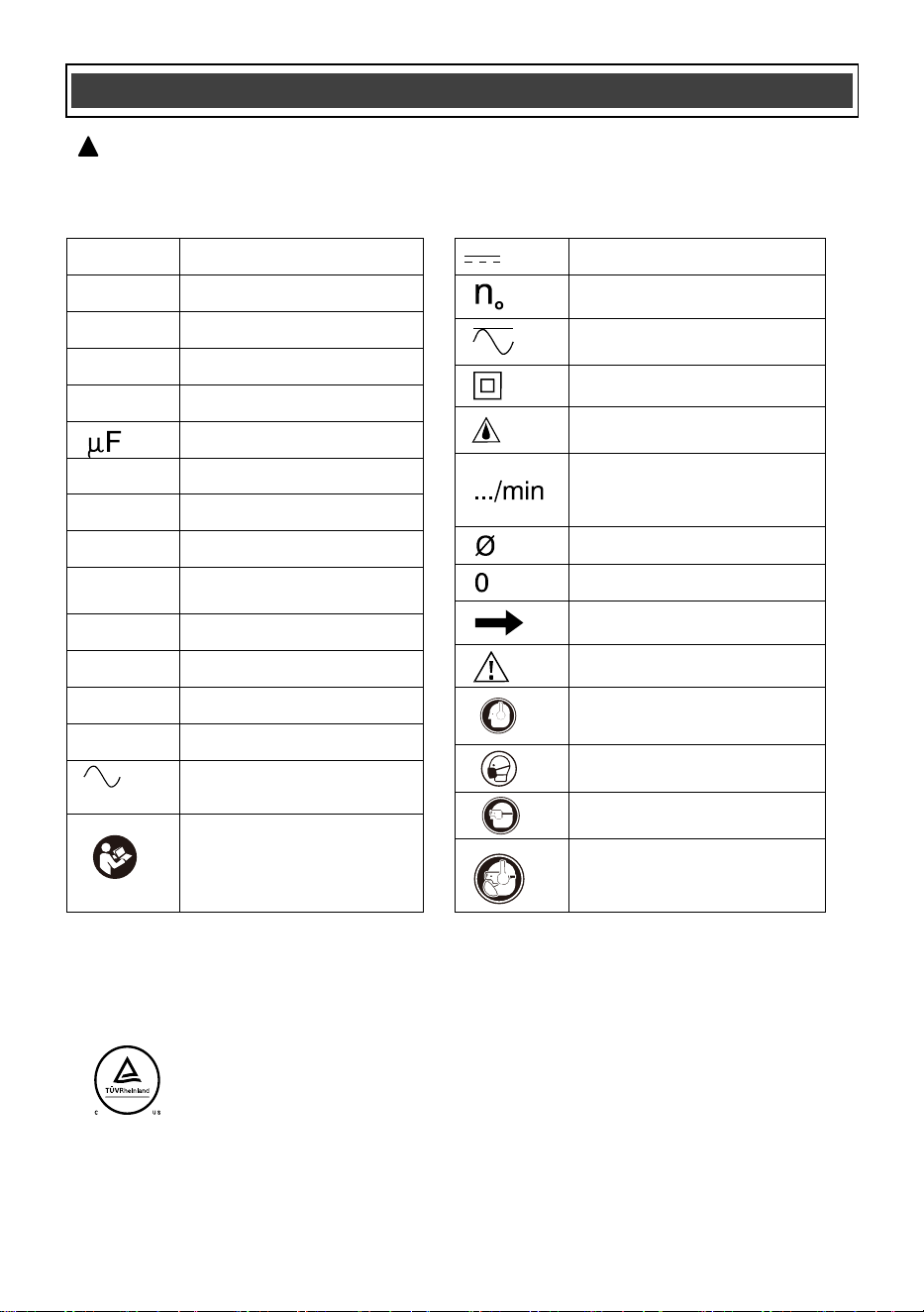
SYMBOLS
WARNING: Some of the following symbols may appear on the circular saw.
Study these symbols and learn their meaning. Proper interpretation of these symbols
will allow for more efficient and safer operation of this tool.
!
This symbol designates that this tool is listed with U.S.
requirements by TÜV Rheinland (Shanghai) Co., Ltd.
Conforms to UL62841-1,UL62841-2-5
Certified to CAN/CSA Std. C22.2 No. 62841-1 and 62841-2-5.
JD5399
Wear hearing protection.
Wear eye protection.
Wear breathing protection.
Read instruction manual.
To reduce the risk of
injury, user must read
instruction manual.
V
Volts
A
Amperes
Hz
Hertz
W
Watts
kW
Kilowatts
Microfarads
kg
Kilograms
H
Hours
N/cm
2
Newtons per square
centimeter
Pa
Pascals
OPM
Oscillations per minute
Min
Minutes
S
Seconds
or a.c.
Alternating current
Direct current
No load speed
Alternating or direct
current
Class II construction
Splash-proof
construction
Revolutions or
reciprocations per
minute
Diameter
Off position
Directional Arrow
Warning symbol
Wear hearing protection.
Wear breathing protection.
Wear eye protection.
or DC
lbs
Pounds, Weight
12
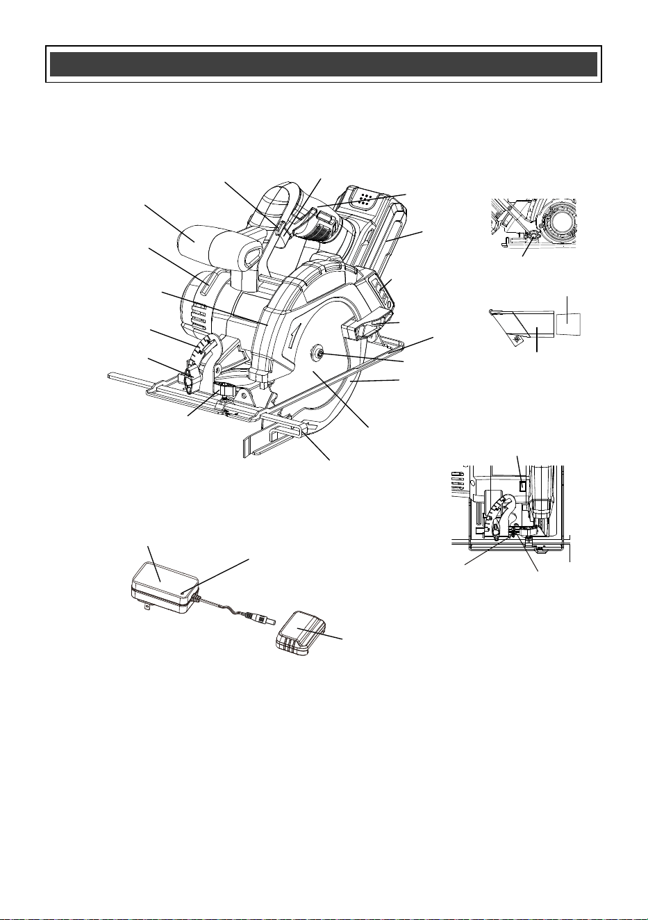
KNOW YOUR CIRCULAR SAW
Battery charger adapter
Charging status
indicator light
Battery charger cap
Battery
Dust extraction port
Main handle
Safety lock-out switch
Front handle
Blade wrench
Upper blade
guard
Bevel gauge
Edge guide
adjustment knob
Edge guide
Blade
Blade screw
Blade guard lever
Depth adjustment knob
Sole plate
Lower blade guard
Spindle lock button
Bevel angle
adjustment knob
Set screw
Lock nut
ON/OFF trigger switch
1-3/8” dust adapter
1-3/8” to 1-1/4”
vacuum adapter
13
ASSEMBLY AND OPERATING
CHARGING THE BATTERY PACK
WARNING: Do not use the charger
outdoors or expose it to wet or damp
conditions. Water entering the charger will
increase the risk of electric shock.
NOTICE: Lithium-Ion battery packs are
shipped partially charged. Before using it
the first time, you must fully charge it.
NOTICE: You can only charge one battery at
a time with the charger provided.
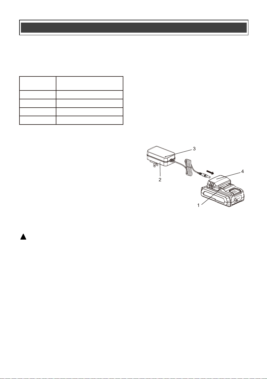
1. Plug the battery charger adapter into the
battery charger cap and then plug the adapter
(2) into a power supply (120V~60Hz). The
charging status indicator LED light (3) will turn
green indicating that the charger is working
correctly.
!
2. Align the raised ribs of the battery (1) with the
battery-mounting slots in the battery charge
cap (4); slide the cap onto the battery. If
installed correctly the charging status indicator
light on the charger will turn red indicating the
battery is charging (see chart on this page) and
the battery charge level indicator lights on the
battery will flash.
3. When the battery is fully charged the light on
the charger will turn green and the lights on the
battery will turn off or keeps on. Once the
charge cap is removed from the battery (never
check while charging cap is installed on the
battery) you may confirm the charge status of
the battery. When fully charged all battery
charge level indicator lights should be lit.
BATTERY CHARGE LEVEL INDICATOR LIGHTS
To check the battery charge level, press the
push button on the battery pack. The LED
indicator lights will show the current charge
levels as indicated in chart below.
NOTE:
If one indicator light begins to flash, the battery
charge level is under 10% capacity and should
be recharged soon.
If three indicator lights begin to flash at a rate of
1 or 2 times per second, the battery is too hot,
and cool the battery till its temperature drops
below 152°F (67°C).
If three indicator lights begin to flash at a rate of
5 times per second, the battery is defective,
please recycle or dispose of batteries properly,
or contact Customer Service.
Indicator
Lights
3 lights on
2 lights on
1 light on
1 light flashing
Battery Charge Level
70%<Charge Level≤100%
40%<Charge Level≤70%
10%<Charge Level≤40%
Charge Level ≤10%
NOTE:
The battery cannot be correctly charged on
the charger if the battery pack is too hot or
too cold and not within normal temperature
range 41°F (5°C) - 113°F (45°C). Allow the
battery pack to reach normal temperature,
and charging will begin.
The battery pack will fully charge if left on
the charger, but it will not overcharge.
A significantly reduced runtime after fully
charging the battery pack indicates that the
batteries are nearing the end of their usable
life and must be replaced.
The charger may become warm during
charging. This is a normal part of its
operation. Always charge in a well-ventilated
area.
Fig. 1
14
ASSEMBLY AND OPERATING
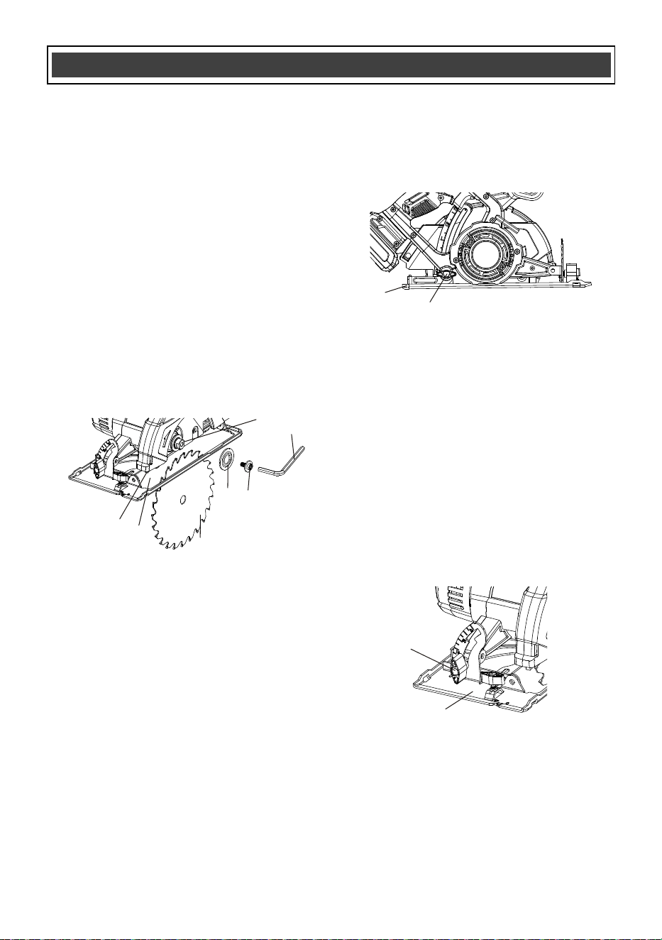
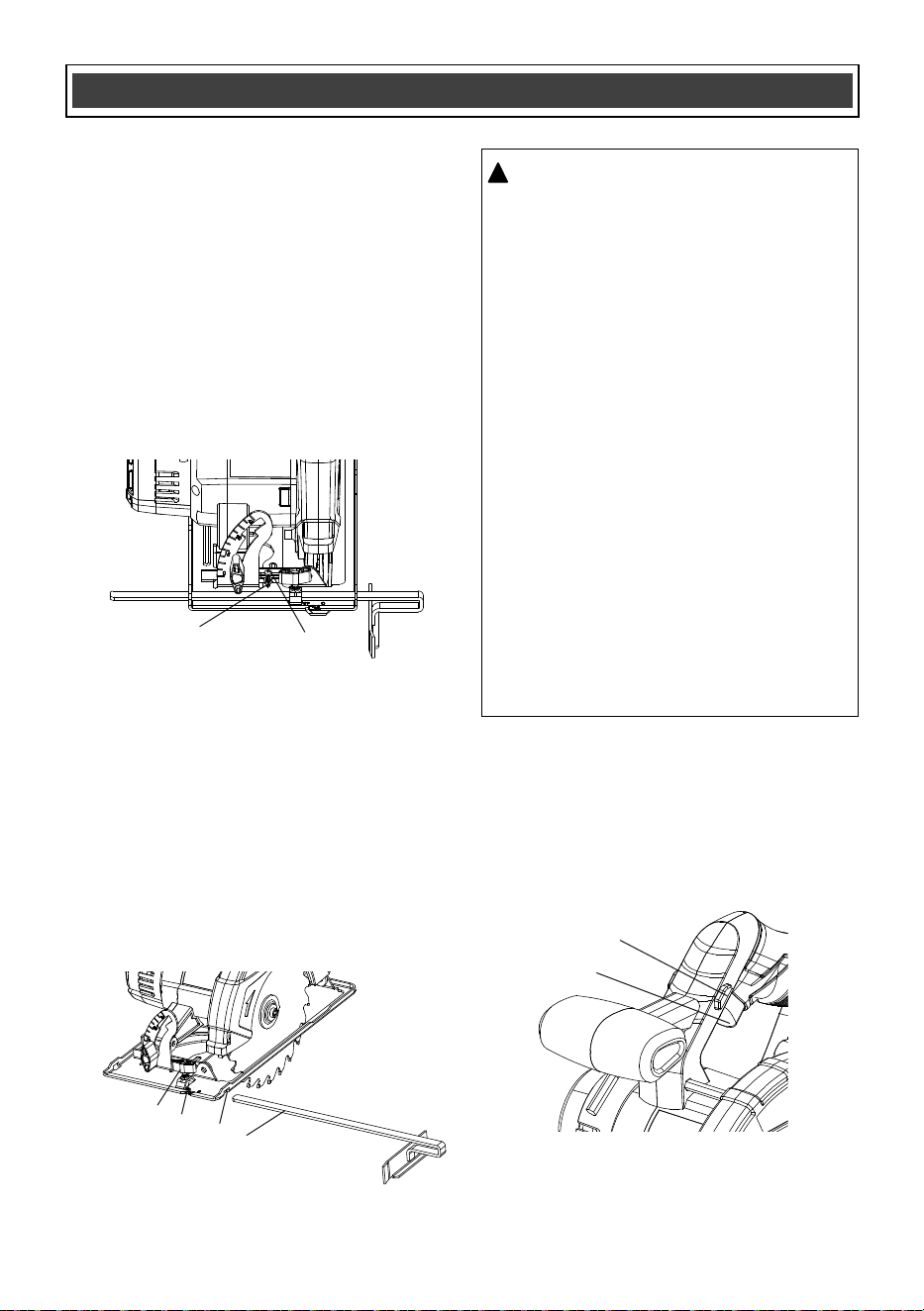
INSTALLING A BLADE
1. Place your right thumb on the spindle-locking
button (1) (Fig. 3).
4. To place blade onto the motor shaft, rotate
the blade guard lever (5) forward and slide
the blade (6) through the slot (7) in the sole
plate until it fits over the motor shaft (8)
(Fig. 5).
2. Place the socket end of the blade wrench
(supplied) (2) on the blade screw (3)
(Fig. 4).
NOTE: The blade wrench is stored on the front
of the motor housing just above the sole plate.
3. While pressing the spindle-locking button,
rotate the blade wrench clockwise until the
blade-locking button engages the blade
shaft. Continue turning the blade wrench
clockwise to remove the blade screw and
the large washer (4).
NOTE: The blade screw has a left-handed
thread and must be turned clockwise to be
removed.
WARNING: Always remove the
battery from the tool before installing or
removing a blade or adjusting the saw
in any way.
!
Fig. 3
Fig. 4
4
1
3
2
Fig. 2
2
1
3
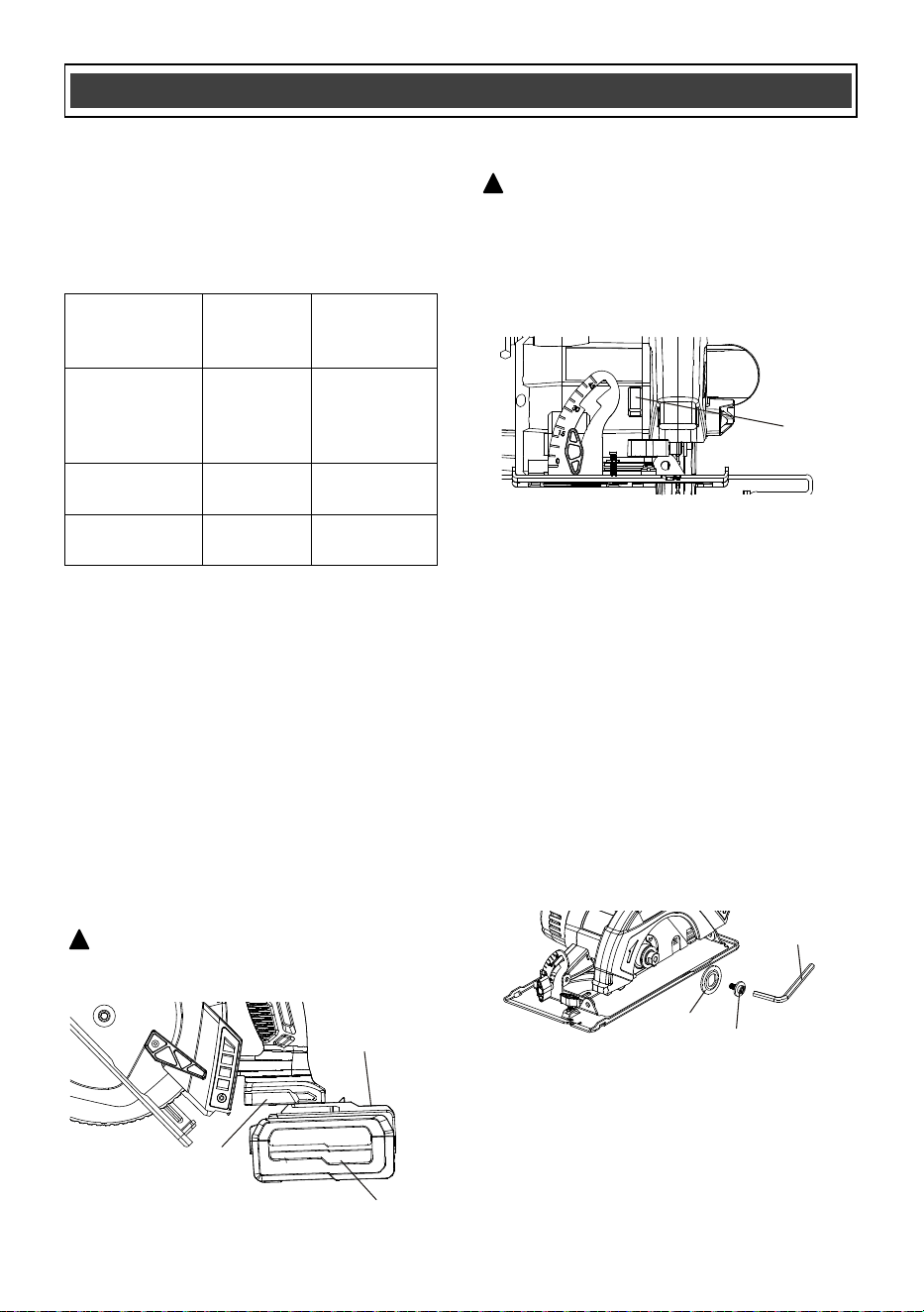
INSTALLING THE BATTERY PACK IN THE
SAW
1. Remove the discharged battery pack (1)
from the tool by pressing the battery
release button (2) on the front of the
battery pack and pulling the battery pack
out of the tool handle (3) (Fig. 2).
2. Insert the fully charged battery pack into
the matching slots in the tool handle where
the discharged battery pack has been
removed.
NOTE: The battery release button will
“click” into place when the battery pack is
fully installed.
WARNING: Do not immerse battery
pack in water. Sudden cooling could cause a
hot battery to explode or leak.
!
CHARGING THE BATTERY CONT’D
If the battery pack is completely discharged
and no LEDs flash when it is connected to
the charger, this indicates a malfunctioning
battery. In this case, do not attempt to
charge the battery.
Charging
status
indicator light
Green NO
Charger
connected
to power
supply
Red YES
Battery is
being charged
Green YES
Battery fully
charged
Charger cap
installed on
battery
Charging
Status
15
ASSEMBLY AND OPERATING
ADJUSTING THE CUTTING DEPTH
The cutting depth of the blade should be set to
suit the thickness of the material being cut. The
cutting depth should be approximately 1/8"
(3 mm) greater than the thickness of the
material being cut.
1. Turn the depth adjustment knob (1) in a
counter clockwise direction (Fig. 6).
2. Pull the sole plate (2) downward until the
correct amount of the blade is protruding
below the sole plate.
NOTE: Never engage the spindle lock while
saw is running, or engage in an effort to stop
the tool. Never turn the saw on while the spindle
lock is engaged. Serious damage to your saw
will result.
NOTE: Make sure the blade teeth are pointing
forward at the bottom of the blade.
5. Place the large flat washer (4) onto the
motor shaft.
NOTE: Make sure the flat sections of the large
washer fit over the matching flat sections on the
motor shaft.
6. Insert the blade screw (3) through the large
flat washer and thread it counterclockwise
into the end of the motor shaft.
7. Lock motor shaft using the shaft-locking
button and firmly tighten the blade screw
using the blade wrench (2).
NOTE: Make sure the screw is NOT
crossthreaded and that the blade does not
wobble when turned by hand.
Fig. 5
4
6
5
7
3
2
8
3. Lock the sole plate at the correct depth by
turning the depth control knob clockwise.
NOTE: Make a test cut on a scrap workpiece
to verify the depth setting.
The sole plate can be tilted to provide bevel
cuts from 0°–50°.
Adjusting the sole plate angle
1. Turn the bevel angle adjustment knob (1)
counter clockwise (Fig. 7).
2. Rotate the sole plate (2) to the desired
angle as shown on the bevel gauge (3).
3. Lock the sole plate at the correct angle by
turning the bevel angle adjustment knob in
a clockwise direction.
NOTE: Make a test cut on a scrap workpiece to
verify the bevel angle setting.
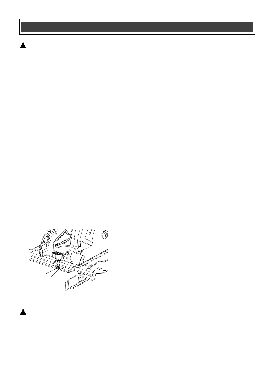
BEVEL CUTTING
Before making right angle cuts, the 0° stop must
be adjusted.
1. Set sole plate angle at 0° and lock it into
position.
2. Make a test cut.
Setting the 0° stop
Fig. 6
Fig. 7
2
2
1
1
16
ASSEMBLY AND OPERATING
The lock-out switch (1) is a safety device
designed to reduce the possibility of accidental-
ly starting the saw (Fig. 10). This switch must be
depressed before the ON/OFF trigger switch (2)
can be depressed.
SAFETY LOCK-OUT SWITCH
Fig. 10
WARNING: For safety reasons, the
operator must read the sections of
this Owner’s Manual entitled "GENERAL
SAFETY WARNINGS", "POWER TOOL
SAFETY","SPECIFIC SAFETYRULES",
"EXTENSION CORD SAFETY" and
"SYMBOLS" before using this circular
saw.
Verify the following every time the circular
saw is used:
1. The Blade is tight and sharp.
Ensure the blade is securely fastened and
in good condition for clean cuts.
2. All adjustments are tight.
Double-check that the depth and bevel
adjustments, as well as the shoe, are
securely locked in place.
3. The workpiece is properly secured.
Make sure the material to be cut is firmly
clamped or supported to prevent move-
ment during the cut.
Safety Glasses and hearing protection are
being worn Always wear safety glasses
and hearing protection to protect yourself
from debris and the saw's noise.
!
2
1
3. Check the cutting angle with a carpenter’s
square. If the cut is not square, readjust
the sole plate angle until it is square.
4. Once the sole plate is producing a square
cut, loosen the adjusting lock nut (1) using
a 9/32" (7 mm) wrench. Turn the set screw
(2) clockwise using a #2 Philips®
(not included) screwdriver until it touches the
sole plate (Fig. 8). While holding the set screw
with the screwdriver, tighten the lock nut.
NOTE: The set screw may have to be loosened
to allow the sole plate to be set at 0°.
1. Loosen the edge guide adjusting knob (1)
(Fig. 9).
2. Slide the edge guide (2) into the edge
guide slot (3). Continue to slide the edge
guide across the sole plate and into the
adjusting knob slot (4) in the sole plate on
the opposite side.
3. Adjust the edge guide to the correct
distance from the blade and tighten the
adjusting knob.
INSTALLING THE EDGE GUIDE
Fig. 9
Fig. 8
2
3
4
1
1
2
17
ASSEMBLY AND OPERATING
ELECTRIC BRAKE
This circular saw is equipped with an electric
brake that quickly stops the blade when the
trigger is released, enhancing safety and
reducing downtime. This safety feature helps
prevent accidental contact with the blade and
allows for quicker, more efficient use.
ON/OFF TRIGGER SWITCH
1. To turn the saw ON, press the safety
lock-out switch with your thumb.
NOTE: The safety lock-out switch can be
pressed from either side of the main handle.
2. While holding the safety lock-out switch in
the pressed position, squeeze the trigger
switch to start the saw.
3. Once the saw starts, release the safety
lock-out switch. The saw will remain
running until the trigger switch is released.
4. To turn the saw OFF, release the ON/OFF
trigger switch.
NOTE: To re-start the saw, the safety lock-out
switch must be pressed again before the
ON/OFF trigger switch is squeezed to start the
saw.
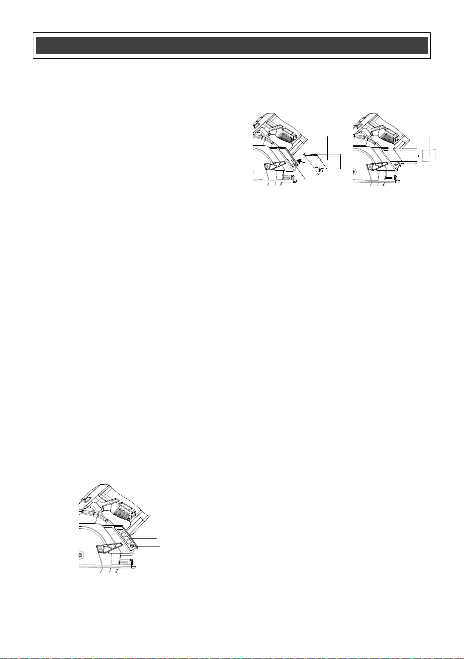
To reduce the amount of loose sawdust
produced while cutting, a workshop vacuum
can be attached to the saw by installing the dust
adapter (1-3/8”) and the 1-3/8” to 1-1/4” vacuum
adapter supplied with the saw.
1. Loosen the fixing screw (1) and remove the
cover plate (2) from the dust extraction port
(Fig. 11).
2. Insert the dust adapter (3) into the the dust
extraction port (4) and tighten the fixing screw
(Fig. 12).
INSTALLING THE DUST AND
VACUUM ADAPTERS
Fig. 11
1
2
NOTE: There are several different types of
blades available. Generally, blades with carbide
tipped teeth cut better and stay sharp longer.
Tooth count and configuration are also
important. High tooth counts cut slower, and are
best suited for making smooth cuts on thinner
materials such as panelling. Use the correct
blade for your application.
GENERAL CUTTING
1. Make any adjustments to the saw before
installing the battery. Adjustments include
cutting depth, cutting angle and edge guide
(if installed).
2. Clearly mark the workpiece to locate the
position of the cut.
3. Hold a smaller workpiece with a vise.
Clamp a larger workpiece to a workbench
or table.
The circular saw is a versatile saw that allows
you to cut many different types of materials.
Some of the materials include:
● Wood products such as lumber,
hardwood, plywood, composit board and
panelling
● Drywall
● Masonite and plastic
MATERIALS THAT REQUIRE EXTRA
ATTENTION
● Wet lumber
● Green lumber (material freshly cut or not
kiln dried)
● Pressure treated lumber (material treated
with preservatives or anti-rot chemicals)
MATERIALS THAT YOU CAN CUT
3. To install the 1-3/8” to 1-1/4” vacuum adapter
(5), insert the smaller end of the adapter into
the dust adapter (Fig. 12).
Fig. 12
3 5
4
18
ASSEMBLY AND OPERATING
1. Set the rip guide foot at the required width
(Fig. 9).
NOTE: When starting the cut, make sure the
blade is parallel to the edge of the workpiece
and the edge guide (rip guide) foot is against
the edge of the workpiece.
2. Proceed with the cut as outlined in
"GENERAL CUTTING" above.
NOTE: As you move the saw through the
workpiece, make sure the guide foot stays in
contact with the workpiece.
RIP GUIDE CUTTING
DANGER: Any workpiece that is not
adequately clamped in place may come
loose and cause serious injury. Never
hold the workpiece in your hand.
!
4. Make sure there are no nails, screws,
clamps or foreign materials in the path of
the saw blade.
5. With both hands firmly gripping the saw,
and with the blade NOT in contact with the
surface to be cut, start the saw by pressing
the safety lock-out switch and then the
ON/OFF trigger switch.
6. Once the saw has reached full speed,
place the front edge of the sole plate on
the workpiece and gradually bring the
moving blade into contact with the
workpiece at the appropriate location.
NOTE: To align the saw blade with the cutting
mark, use the guide marks on the front of the
sole plate (Fig. 13). Use the 0° cutting mark (1)
for right angle cuts. Use only the 45° mark (2)
for 45° cuts. The 45° mark will allow for the
extra material needed for the angle cut. Always
make a test cut on a scrap workpiece before
cutting the new material.
WARNING: Do not force the circular
saw. Use only enough force to keep the
blade cutting at full speed. Excessive
pressure on the blade will cause it to
slow down and overheat, resulting in
poor cut quality and damage to the
motor.
!
Fig. 13
1
2

19
MAINTENANCE
GENERAL
WARNING: When servicing, use only
identical replacement parts. The use of any
other part may create a hazard or cause
product damage.
DO NOT use solvents when cleaning plastic
parts. Plastics are susceptible to damage from
various types of commercial solvents and may
be damaged by their use. Use a clean cloth to
remove dirt, dust, oil, grease etc.
WARNING: Do not allow brake fluids,
gasoline, petroleum-based products,
penetrating oils, etc. to come into contact
with plastic parts. They contain chemicals
that can damage, weaken or destroy plastic.
DO NOT abuse power tools. Abusive practices
can damage the tool and the workpiece.
WARNING: DO NOT attempt to modify
tools or create accessories. Any such
alteration or modification is misuse and
could result in a hazardous condition leading
to possible serious injury. It will also void
the warranty.
LUBRICATION
All of the bearings in this tool are lubricated with
a sufficient amount of high-grade lubricant for
the life of the unit under normal conditions.
Therefore, no further lubrication is required.
!
!
!
BATTERY PACK REMOVAL AND
PREPARATION FOR RECYCLING
To preserve our natural resources, please
recycle or dispose of batteries properly.
The batteries accompanying this tool may
contain chemicals and metals that are harmful
to the environment. Never dispose of
rechargeable batteries in your normal household
garbage or in landfill sites, because they will add
to the pollution of the environment.
Consult your local waste authority for
information regarding available recycling and
disposal options.
WARNING: Upon removal of the battery
pack, cover the terminals of the battery pack
with electrical tape or heavy-duty adhesive
tape. Never touch both terminals with metal
objects or body parts, because a short
circuit may result. Keep away fro
m children.
Do not attempt to destroy or disassemble
battery pack or remove any of its
components. Rechargeable batteries must
be recycled or disposed of properly. Failure
to comply with these warnings could result
in fire and serious injury.
!
20
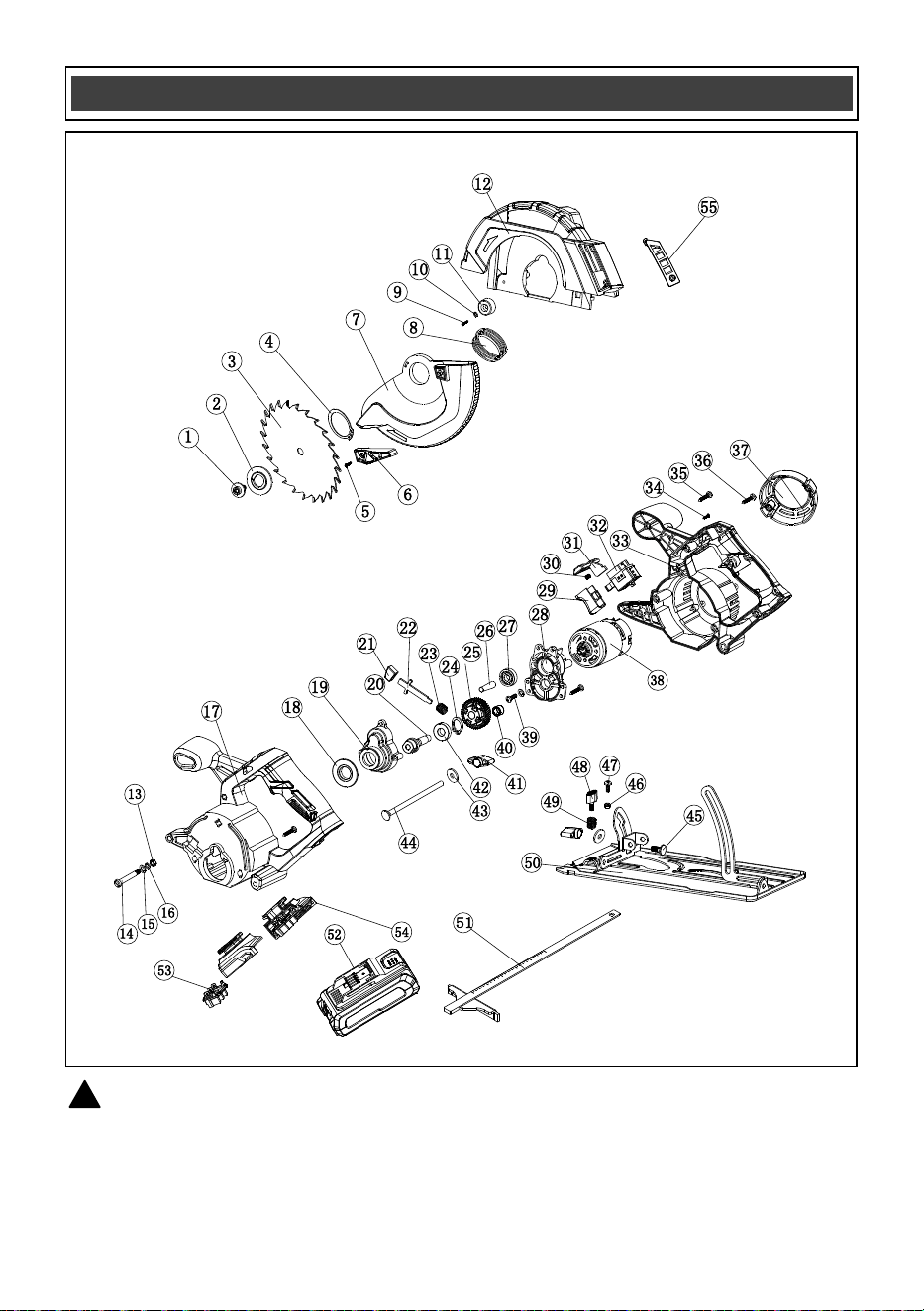
WARNING: When servicing, use only original equipment replacement parts. The use of any
other parts may create a safety hazard or cause damage to the circular saw.
Any attempt to repair or replace electrical parts on this tool may create a safety hazard unless repairs
are performed by a qualified technician. For more information, call the Toll-free Helpline, at
1-866-349-8665.
!
AVAILABLE PARTS

21
Key # Part # Part Name
1 4020080063 Screw M6x13
2 2030030246 Outer flange
3 6070030004 Blade
4 4100020014 Circlip, dia. 28
5 4030010165 Tapping screw ST2.9x7
6 3120100054 Guard lever
7 3160040092 Guard
8 2050050053 Torsional spring
9 4030010244 Tapping screw ST3.9x10
10 4040010044 Flat washer
11 3140090026 Guard stopper
12 3160040093 Upper guard
13 4060010022 Hex nut M5
14 2040140057 Cross pin screw
15 4040010011 Flat washer
16 4040030003 Spring washer 5
17 3010070031 Housing
18 2010140053 Inner flange
19 3160090098 Gear box cover
20 2040050146 Main shaft
21 3120020141 Spindle lock button
22 2030250017 Spindle lock rod
23 2050060233 Spring
24 4100020012 Circlip 10
25 2010020018 Big gear
26 2040070024 Motor gear
27 4010010022 Bearing 6900
28 3150070095 Gearing box
29 3120010101 Switch button
30 2050060218 Spring
31 3120040063 Lock-off lever
32 1060190008 Switch
33 3140070002
Springy block
34 4030010246 Tapping screw ST3.9x8
35 4030010106 Tapping screw ST3.9x19
36 4030010074 Tapping screw ST3.9x14
37 3160010069 Motor cover
38 1030240001 Motor
39 4020010170 Screw M5x32
40 4010020044 Needle bearing
41 1180050050 Depth lock knob
42 4010010022 Bearing 6900
43 2030020116 Washer
44 4050040015
Cup head square neck bolt M6 L98
45 4050040014 Cup head square neck bolt M6 L15
46 4060010005 Hex nut 4
AVAILABLE PARTS
Always order by PART NUMBER, not by key number.

22
Key # Part # Part Name
47 4020010053 Screw M4x14
48 1180050051 Edge guide knob
49 2050060228 Spring
50 1150020131 Base plate
51 6210040013 Edge guide
52 1290090062
Battery
53 3150170032 Contact plate
54 3010060023 Foot
55 3180040145 Cover plate
AVAILABLE PARTS

2
Rev 2.3 31/10/2025
Distributed by: Menard, Inc., Eau Claire, WI 54703
PERFORMAX
®
20 VOLT CIRCULAR SAW
23
2-YEAR LIMITED WARRANTY:
This PERFORMAX
®
brand power tool carries a 2-Year Limited Warranty to the
original purchaser. If, during normal use, this PERFORMAX
®
power tool breaks
or fails due to a defect in material or workmanship within two (2) years from the
date of original purchase, simply bring this tool with the original sales receipt
back to your nearest MENARDS® retail store. At its discretion, PERFORMAX
®
agrees to have the tool or any defective part(s) repaired or replaced with the
same or similar PERFORMAX
®
product or part free of charge, within the stated
warranty period, when returned by the original purchaser with original sales
receipt. Not withstanding the foregoing, this limited warranty does not cover any
damage that has resulted from abuse or misuse of the Merchandise. This
warranty: (1) excludes expendable parts including but not lim
ited to blades,
brushes, belts, bits, light bulbs, and/or batteries; (2) shall be void if this tool is
used for commercial and/or rental purposes; and (3) does not cover any losses,
injuries to persons/property or costs. This warranty does give you specific legal
rights and you may have other rights, which vary from state to state. Be careful,
tools are dangerous if improperly used or maintained. Seller’s employe
es are
not qualified to advise you on the use of this Merchandise. Any oral
representation(s) made will not be binding on seller or its employees. The rights
under this limited warranty are to the original purchaser of the Merchandise and
may not be transferred to any subsequent owner. This limited warranty is in lieu
of all warranties, expressed or implied including warranties or merchantability
and fitness for a particular
purpose. Seller shall not be liable for any special,
incidental, or consequential damages. The sole exclusive remedy against the
seller will be for the replacement of any defects as provided herein, as long as
the seller is willing or able to replace this product or is willing to refund the
purchase price as provided above. For insurance purposes, seller is not allowed
to demonstrate any of these power tools for you.
Fo
r questions / comments, technical assistance or repair parts –
Please Call Toll Free at: 1
-866-349-8665 (M-F 9am-5pm EST) or email
SAVE YOUR RECEIPTS. THIS WARRANTY IS VOID WITHOUT THEM.