
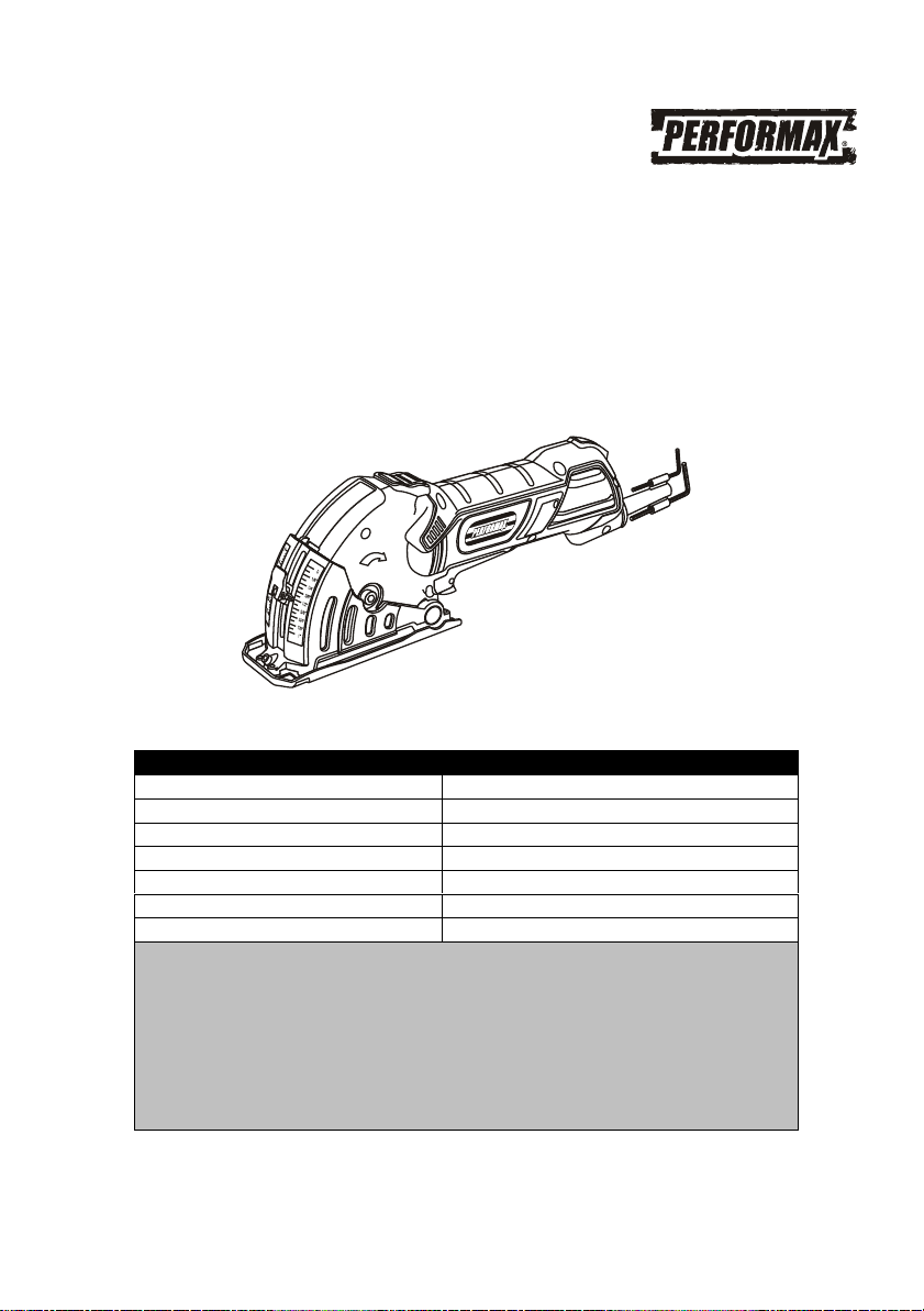
4.8AMP MULTI-CUT SAW
WITH MITER CUTTING BASE
241-0951
Owner’s Manual
PRODUCT SPECIFICATIONS
Rating:
120 V, 60 Hz, AC
Amperes:
4.8 Amperes
Speed:
4,000 RPM (no load)
Blade diameter:
3
3
/
8
" (85 mm)
Arbor:
15 mm
Depth of cut:
0–1" (0–25 mm)
Depth of cut with miter guide:
0–7/8" (0–22 mm)
Need Assistance?
Call us on our toll free customer support line:
1-866-349-8665
Technical questions
Replacement parts
Parts missing from package

2
Product specifications ………….………………………………………………………………...
1
Table of contents ……………………………………………………………………..................
2
General safety warnings …………………………………………………………………………
3–4
Eye, ear & lung protection ……………………………………………………………………….
3–4
Electrical safety …………………………………………………………………………………...
4
Power tool safety ……………………………………………………………………..................
5–6
General warning ………………………………………………………………………………….
5
Work area ………………………………………………………………….……………………...
5
Electrical safety …………………………………………………………………………………...
5
Personal safety …………………………………………………………………………………...
5
Power tools use and care ………………………………………………………………………..
6
Service …………………………………………………………………………………………….
6
Specific safety rules ……………………………………………………………………………...
7–9
Causes and operator prevention of kickback ………………………………………………….
7–8
Additional specific safety rules ………………………………………………………………….
8–9
Extension cord safety …………………………………………………………………………….
10
Symbols ……………………………………………………………………………………………
11
Know your multi-cut saw …………………………………………………………………………
12
Contents …………………………………………………………………………………………...
13
Assembly and operating …………………………………………………………………………
14–20
Removing the blade ……………………………………………………………………………...
14
Selecting the correct blade ………………………………………………………………………
14
Installing a blade ………………………………………………………………………………….
15
Adjusting the cutting depth ………………………………………………………………………
15
Installing the edge guide …………………………………………………………………………
15–16
Installing the vacuum hose ………………………………………………………………………
16
ON/OFF switch ……………………………………………………………………………………
16–17
Cutting (without the edge guide) ………………………………………………………………..
17–18
Cutting (with the edge guide) ……………………………………………………………………
18
Assembling the cutting & miter guide ………………………………………………………….
18–19
Cutting with the cutting & miter guide ………………………………………………………….
19–20
Maintenance ………………………………………………………………………………………
20–21
Replacing carbon motor brushes ……………………………………………………………….
20–21
General maintenance …………………………………………………………………………….
21
Lubrication ………………………………………………………………………………………...
21
Exploded view – multi-cut saw …………………………………………………………………
22
Exploded view – cutting & miter guide …………………………………………………………
23
Parts list – multi-cut saw …………………………………………………………………………
24–26
Parts list – cutting & miter guide ………………………………………………………………..
26
Warranty ……………………………………………………………………….………………….
27
TABLE OF CONTENTS
3
EYE, EAR & LUNG PROTECTION
This instruction manual includes the following:
General Safety Rules
Specific Safety Rules and Symbols
Functional Description
Assembly
Operation
Maintenance
Accessories
!
ALWAYS WEAR EYE PROTECTION THAT CONFORMS WITH CSA
REQUIREMENTS or ANSI SAFETY STANDARD Z87.1
FLYING DEBRIS can cause permanent eye damage. Prescription
eyeglasses ARE NOT a replacement for proper eye protection.
WARNING: Non-compliant eyewear can cause serious injury if
broken during the operation of a power tool.
SAVE THESE INSTRUCTIONS FOR REFERENCE
WARNING: Use hearing protection, particularly during extended
periods of operation of the tool, or if the operation is noisy.
!
GENERAL SAFETY WARNINGS
WARNING: Before using this tool or any of its accessories, read this
manual and follow all Safety Rules and Operating Instructions. The important
precautions, safeguards and instructions appearing in this manual are not
meant to cover all possible situations. It must be understood that common
sense and caution are factors which cannot be built into the product.
!
4
ELECTRICAL SAFETY
WARNING: To avoid electrical hazards, fire hazards or damage to the
tool, use proper circuit protection.
This tool is wired at the factory for 120V AC operation. It must be
connected to a 120V AC, 15 AMP circuit that is protected by a time-delayed
fuse or circuit breaker. To avoid shock or fire, replace power cord
immediately if it is worn, cut or damaged in any way.
GENERAL SAFETY WARNINGS
WEAR A DUST MASK THAT IS DESIGNED TO BE USED WHEN
OPERATING A POWER TOOL IN A DUSTY ENVIRONMENT.
WARNING: Dust that is created by power sanding, sawing, grinding,
drilling, and other construction activities may contain chemicals that are
known to cause cancer, birth defects, or other genetic abnormalities. These
chemicals include:
Lead from lead-based paints
Crystalline silica from bricks, cement, and other masonry products
Arsenic and chromium from chemically treated lumber
The level of risk from exposure to these chemicals varies, according to how
often this type of work is performed. In order to reduce exposure to these
chemicals, work in a well-ventilated area, and use approved safety
equipment, such as a dust mask that is specifically designed to filter out
microscopic particles.
!

WARNING: Read all safety warnings
and instructions. Failure to follow the warnings
and instructions may result in electric shock, fire
and/or serious injury.
Save all warnings and instructions for future
reference.
Work area safety
Keep work area clean and well lit. Cluttered or
dark areas invite accidents.
Do not operate power tools in explosive
atmospheres, such as in the presence of
flammable liquids, gases or dust. Power tools
create sparks which may ignite the dust or
fumes.
Keep children and bystanders away while
operating a power tool. Distractions can cause
you to lose control.
Electrical safety
Power tool plugs must match the outlet.
Never modify the plug in any way. Do not
use any adapter plugs with earthed
(grounded) power tools. Unmodified plugs and
matching outlets will reduce risk of electric
shock.
Avoid body contact with earthed or
grounded surfaces such as pipes, radiators,
ranges and refrigerators. There is an
increased risk of electric shock if your body is
earthed or grounded.
Do not expose power tools to rain or wet
conditions. Water entering a power tool will
increase the risk of electric shock.
Do not abuse the cord. Never use the cord
for carrying, pulling or unplugging the power
tool. Keep cord away from heat, oil, sharp
edges or moving parts. Damaged or
entangled cords increase the risk of electric
shock.
When operating a power tool outdoors, use
an extension cord suitable for outdoor use.
Use of a cord suitable for outdoor use reduces
the risk of electric shock.
If operating a power tool in a damp location
is unavoidable, use a residual current device
(RCD) protected supply. Use of a ground fault
circuit interrupter (GFCI) reduces the risk of
electric shock.
Personal safety
Stay alert, watch what you are doing and use
common sense when operating a power tool.
Do not use a power tool while you are tired
or under the influence of drugs, alcohol or
medication. A moment of inattention while
operating power tools may result in serious
personal injury.
Use personal protective equipment. Always
wear eye protection. Protective equipment
such as dust mask, non-skid safety shoes, hard
hat, or hearing protection used for appropriate
conditions will reduce personal injuries.
Prevent unintentional starting. Ensure the
switch is in the off-position before
connecting to power source and/or battery
pack, picking up or carrying the tool.
Carrying power tools with your finger on the
switch or energizing power tools that have the
switch on invites accidents.
Remove any adjusting key or wrench before
turning the power tool on. A wrench or a key
left attached to a rotating part of the power tool
may result in personal injury.
Do not overreach. Keep proper footing and
balance at all times. This enables better
control of the power tool in unexpected
situations.
Dress properly. Do not wear loose clothing
or jewelry. Keep your hair, clothing and
gloves away from moving parts. Loose
clothes, jewelry or long hair can be caught in
moving parts.
If devices are provided for the connection of
dust extraction and collection facilities,
ensure these are connected and properly
used. Use of dust collection can reduce dust-
related hazards
POWER TOOL SAFETY
!
5

6
Power tool use and care
Do not force the power tool. Use the correct
power tool for your application. The correct
power tool will do the job better and safer at the
rate for which it was designed.
Do not use the power tool if the switch does
not turn it on and off. Any power tool that
cannot be controlled with the switch is
dangerous and must be repaired.
Disconnect the plug from the power source
and/or the battery pack from the power tool
before making any adjustments, changing
accessories, or storing power tools. Such
preventive safety measures reduce the risk of
starting the power tool accidentally.
Store idle power tools out of the reach of
children and do not allow persons unfamiliar
with the power tool or these instructions to
operate the power tool. Power tools are
dangerous in the hands of untrained users.
Maintain power tools. Check for
misalignment or binding of moving parts,
breakage of parts and any other condition
that may affect the power tool’s operation. If
damaged, have the power tool repaired
before use. Many accidents are caused by
poorly maintained power tools.
Keep cutting tools sharp and clean. Properly
maintained cutting tools with sharp cutting
edges are less likely to bind and are easier to
control.
Use the power tool, accessories and tool bits
etc. in accordance with these instructions,
taking into account the working conditions
and the work to be performed. Use of the
power tool for operations different from those
intended could result in a hazardous situation.
Hold power tool by insulated gripping
surfaces when performing an operation
where the cutting tool may contact hidden
wiring or its own cord. Contact with a "live"
wire will make exposed metal parts of the tool
"live" and shock the operator.
Use clamps or another practical way to
secure and support the workpiece to a stable
platform. Holding the work by hand or against
your body leaves it unstable and may lead to
loss of control.
Service
Have your power tool serviced by a qualified
repair person using only identical
replacement parts. This will ensure that the
safety of the power tool is maintained.
POWER TOOL SAFETY
SAVE THESE INSTRUCTIONS FOR REFERENCE

7
WARNING: Know your multi-cut saw.
Do not plug the tool into the power source
until you have read and understand this
Instruction Manual. Learn the tool’s
applications and limitations, as well as the
specific potential hazards related to this tool.
Following this rule will reduce the risk of electric
shock, fire, or serious injury.
Always wear eye protection. Any
power tool can throw foreign
objects into your eyes and cause
permanent eye damage.
ALWAYS wear safety goggles (not glasses) that
comply with ANSI safety standard Z87.1.
Everyday glasses have only impact resistant
lenses. They ARE NOT safety glasses.
WARNING: Glasses or goggles not in
compliance with ANSI Z87.1 could cause
serious injury when they break.
Always keep hands out of the path of the saw
blade. Avoid awkward hand positions where a
sudden slip could cause your hand to move into
the path of the saw blade.
DANGER: Keep hands away from
cutting area and the blade. Keep your
second hand on the tool. If both hands are
holding the saw, they cannot be cut by the
blade.
Do not reach underneath the workpiece. The
guard cannot protect you from the blade below
the workpiece.
Adjust the cutting depth according to the
thickness of the workpiece. Less than a full
tooth of the blade teeth should be visible below
the workpiece or approximately 1/8" (3 mm).
Never hold piece being cut in your hands or
across your leg. Secure the workpiece to a
stable platform. It is important to support the
work properly to minimize body exposure, blade
binding, or loss of control.
Hold power tool by insulated gripping
surfaces when performing an operation
where the cutting tool may contact hidden
wiring or its own cord. Contact with a “live”
wire will also make exposed metal parts of the
power tool “live” and shock the operator.
When ripping always use a straight edge
guide. This improves the accuracy of cut and
reduces the chance of the blade binding.
Always use blades with correct size and
shape (diamond versus round) of arbor
holes. Blades that do not match the mounting
hardware of the saw will run eccentrically,
causing loss of control.
Never use damaged or incorrect blade
washers or bolt. The blade washers and bolt
were specially designed for your saw, for
optimum performance and safety of operation.
CAUSES AND OPERATOR PREVENTION OF
KICKBACK
Kickback is a sudden reaction to a pinched,
bound or misaligned saw blade, causing an
uncontrolled saw to lift up and out of the
workpiece toward the operator;
When the blade is pinched or bound tightly by
the kerf closing down, the blade stalls and the
motor reaction drives the unit rapidly back
toward the operator.
If the blade becomes twisted or misaligned in
the cut, the teeth at the back edge of the blade
can dig into the top surface of the wood causing
the blade to climb out of the kerf and jump back
toward the operator.
Kickback is the result of saw misuse and/or
incorrect operating procedures or conditions and
can be avoided by taking proper precautions as
given below:
Maintain a firm grip with both hands on the
saw and position your arms to resist
kickback forces. Position your body to the
left or right side of the blade, but not in line
with the blade. Kickback could cause the saw
to jump backwards, but kickback forces can be
controlled by the operator, if proper precautions
are taken.
SPECIFIC SAFETY RULES
!
!
!

8
CAUSES AND OPERATOR PREVENTION OF
KICKBACK – cont’d
When the blade is binding, or when
interrupting a cut for any reason, release the
trigger and hold the saw motionless in the
material until the blade comes to a complete
stop. Never attempt to remove the saw from
the work or pull the saw backward while the
blade is in motion or kickback may occur.
Investigate and take corrective actions to
eliminate the cause of blade binding.
When restarting a saw in the workpiece,
center the saw blade in the kerf and check
that saw teeth are not engaged into the
material. If the saw blades are binding, it may
walk up or kickback from the workpiece as the
saw is restarted.
Support large panels to minimize the risk of
blade pinching and kickback. Large panels
tend to sag under their own weight. Supports
must be placed under the panel on both sides,
near the line of cut and near the edge of the
panel.
Do not use dull or damaged blades.
Unsharpened or improperly set blades produce
narrow kerf causing excessive friction, blade
binding and kickback.
ADDITIONAL SPECIFIC SAFETY RULES
Use extra caution when making a "plunge
cut" into existing walls or other blind areas.
The protruding blade may cut objects that can
cause kickback.
Check the lower guard for proper closing
before each use. Do not operate the saw if
the lower guard does not move freely and
close instantly. Never clamp or tie the lower
guard into the open position. If the saw is
accidentally dropped, the lower guard may be
damaged. Raise the lower guard with the
retracting handle and make sure it moves freely
and does not touch the blade or any other part
in all depths of cuts.
Check the operation of the lower guard
spring. If the guard and the spring are not
operating properly, they must be serviced
before use. The lower guard may operate
sluggishly due to damaged parts, gummy
deposits, or a build-up of debris.
The lower guard should be retracted
manually only for special cuts such as
"plunge cuts" and "compound cuts". Raise
lower guard by retracting handle and as
soon as the blade enters the material, the
lower guard must be released. For all other
sawing, the lower guard should operate
automatically.
Always observe that the lower guard is
covering the blade before placing saw down
on the bench or on the floor. An unprotected,
coasting blade will cause the saw to walk
backwards, cutting whatever is in its path. Be
aware of the time it takes for the blade to stop
after the switch is released.
Never operate the saw while it is being carried
to another location. The blade guard may be
open and potentially cause serious injury.
If the switch fails to turn the saw ON or OFF
properly, stop using it immediately and have the
saw switch repaired.
Always allow the saw to reach full speed before
beginning the cut.
Never use the side of the blade for cutting.
When making horizontal cuts, make sure the
weight of the tool is not forcing the side of the
blade to do the cutting. This will reduce the risk
of kickback.
Make sure there are no nails or foreign objects
in the area of the workpiece to be cut.
Never lay workpiece on hard surfaces like
concrete, stone, etc. The protruding blade may
cause tool to jump.
DANGER: To avoid injury from
accidental starting, always remove the plug
from the power source before making any
adjustments and before installing or
removing a saw blade.
SPECIFIC SAFETY RULES
!

9
ADDITIONAL SPECIFIC SAFETY RULES –
cont’d
When replacing the blade, make sure the
replacement blade is 3 3/8" in diameter and
is rated for at least 6,000 RPM. Installing an
incorrect blade will result in possible injury and
poor cutting action.
After changing a blade or making
adjustments, make sure the blade clamp
screw is securely tightened. Loose blades
and adjustment devices will be violently thrown.
Never touch the blade during or immediately
after use. After use the blade is too hot to be
safely touched with bare hands.
SPECIFIC SAFETY RULES

10
WARNING: Keep the extension cord
clear of the working area. Position the cord so
it will not get caught on the workpiece, tools or
any other obstructions while you are working
with the power tool.
Make sure any extension cord used with this
tool is in good condition. When using an
extension cord, be sure to use one of heavy
enough gauge to carry the current the tool will
draw. An undersized cord will cause a drop in
line voltage resulting in loss of power and
overheating.
The table at right shows the correct size to use
according to cord length and nameplate ampere
rating. If in doubt, use the next heavier gauge.
The smaller the gauge number the heavier the
cord.
Be sure your extension cord is properly wired
and in good condition. Always replace a
damaged extension cord or have it repaired by a
qualified electrician before using it. Protect your
extension cord from sharp objects, excessive
heat and damp or wet areas.
Use a separate electrical circuit for your power
tools. This circuit must not be less than 14
gauge wire and should be protected with either
a 15 AMP time delayed fuse or circuit breaker.
Before connecting the power tool to the power
source, make sure the switch is in the OFF
position and the power source is the same as
indicated on the nameplate. Running at lower
voltage will damage the motor.
WARNING: Repair or replace damaged
or worn extension cords immediately.
Select the appropriate extension cord gauge
and length using the chart below.
When operating a power tool outdoors, use
an outdoor extension cord marked "W-A" or
"W". These cords are rated for outdoor use and
reduce the risk of electric shock.
WARNING: Keep the extension cord
clear of the working area. Position the cord
so it will not get caught on the workpiece,
tools or any other obstructions while you are
working with the power tool.
MINIMUM GAUGE (AWG)
EXTENSION CORDS (120V use only)
Amperage
rating
Total length
More
than
Not
more
than
25'
(7.5 m)
50'
(15 m)
100'
(30 m)
150'
(45 m)
0
6
18
16
16
14
6
10
18
16
14
12
10
12
16
16
14
12
12
16
14
12
Not Applicable
EXTENSION CORD SAFETY
!
!
!
11
This symbol designates that this tool is listed
with Canadian requirements by
ETL Testing Laboratories, Inc.
Conforms to UL Std. 60745-1 and 60745-2-5.
Certified to CAN/CSA Std. C22.2 No. 60745-1
and 60745-2-5.
3042597
JD3522U
LISTED
V
Volts
A
Amperes
Hz
Hertz
W
Watts
kW
Kilowatts
Microfarads
L
Liters
kg
Kilograms
H
Hours
N/cm
2
Newtons per square
centimeter
Pa
Pascals
OPM
Oscillations per minute
Min
Minutes
S
Seconds
or a.c.
Alternating current
Three-phase alternating
current
Three-phase alternating
current with neutral
Direct current
No load speed
Alternating or direct
current
Class II construction
Splash-proof
construction
Watertight construction
Protective grounding at
grounding terminal,
Class I tools
Revolutions or
reciprocations per
minute
Diameter
Off position
Arrow
Warning symbol
Wear your safety
glasses
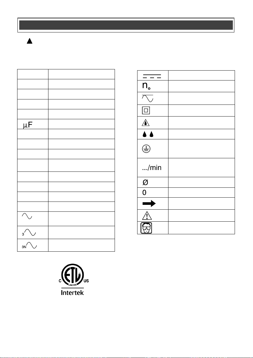
SYMBOLS
WARNING: Some of the following symbols may appear on the multi-cut saw.
Study these symbols and learn their meaning. Proper interpretation of these symbols
will allow for more efficient and safer operation of this tool.
!
12
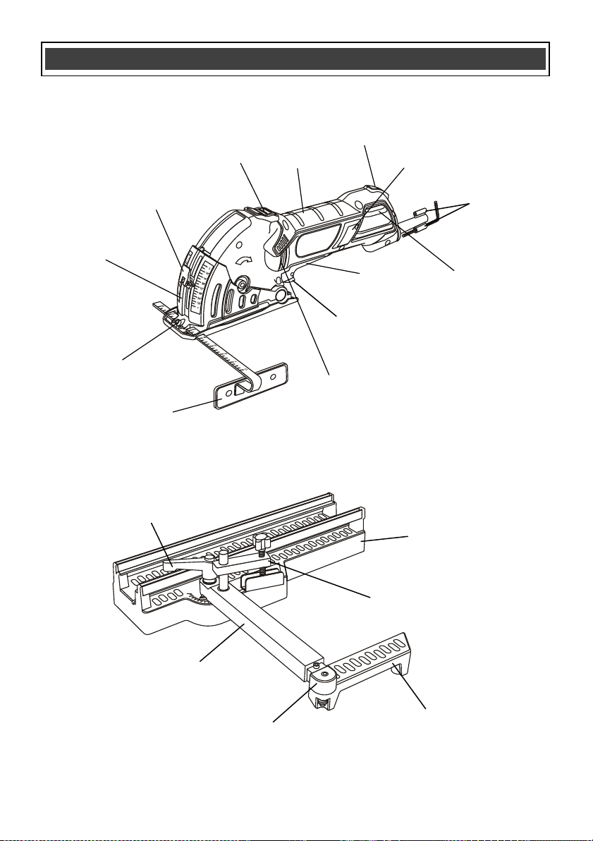
KNOW YOUR MULTI-CUT SAW
Motor
vents
Power ON
light
Cutting
depth knob
Blade
guard
Main
handle
Blade guard
release
ON/OFF
trigger
switch
Motor brush
cover
Rip guide
locking screw
Edge guide
Lock-off
trigger
Motor
vents
Hex key
holders
Cutting & Miter Guide
Multi-cut Saw
Miter clamping
lever
Hold down
clamp assembly
Outer support
arm
Inner support
arm extension
Inner support
arm
Main housing
13
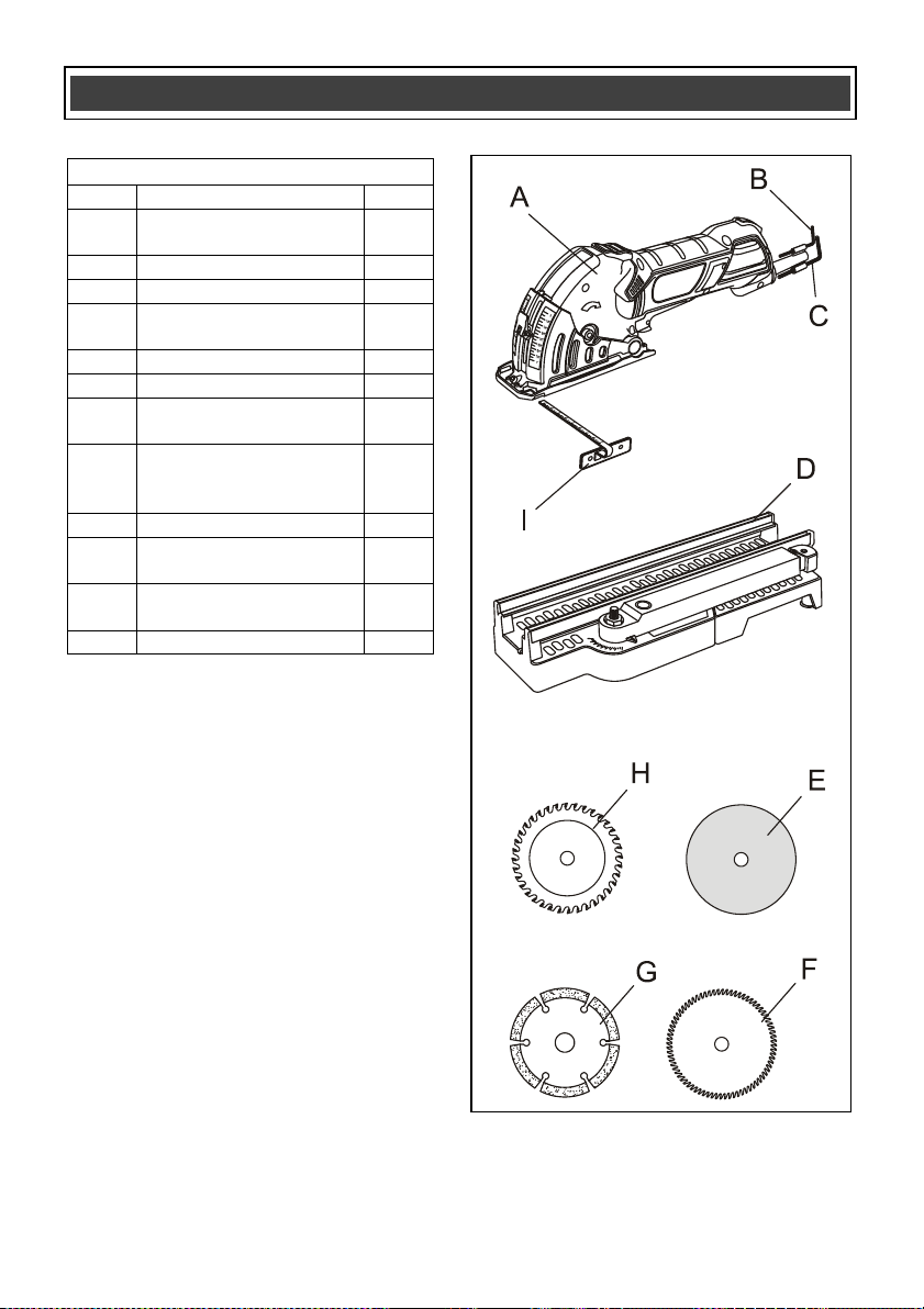
CONTENTS
MULTI-CUT SAW COMPONENTS
KEY
DESCRIPTION
QTY
A
Multi-cut saw
assembly
1
B
Hex key – 3 mm
1
C
Hex key – 5 mm
1
D
Cutting & miter base
assembly
1
E
Corundum disc
5
F
Super cut blade – 80T
1
G
Segmented diamond
wheel
1
H
Carbide tipped blades
● 24 teeth
● 36 teeth
1
1
I
Edge guide
1
Vacuum hose
(not illustrated)
1
Tote bag
(not illustrated)
1
Owner’s manual
1
14
This multi-cut precision saw is a versatile tool
that is designed for use in confined work
spaces. By selecting the appropriate cutting
blades, it will cut copper and aluminum tubing,
ceramic and marble tile, and assorted wood
products. The following assembly and operating
instructions will explain the tool and its operation
in detail.
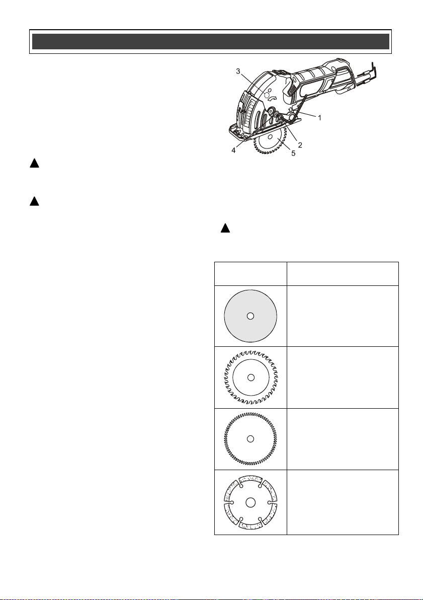
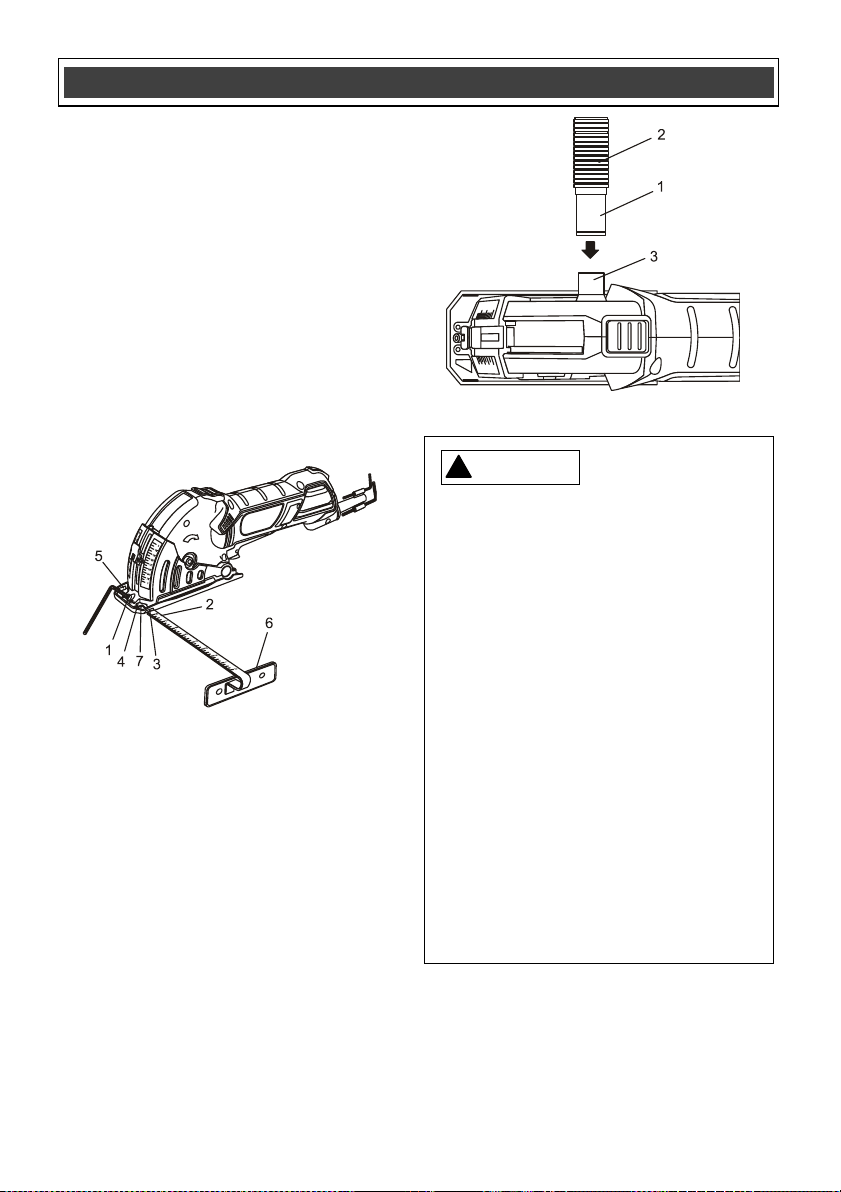
REMOVING THE BLADE
WARNING: Always unplug the tool from
the power source before making any
adjustments or changing the blade.
WARNING: Always be extremely careful
when handling blades. They will be
extremely hot immediately after use. They
are also very sharp and may cause serious
injury.
1. Lay the tool on its right hand side on a
workbench or other suitable work surface.
NOTE: Protect the work surface with
cardboard or a cloth.
2. Insert the 5 mm hex key (1) into the arbor
screw (2) on the LEFT side of the tool
(Fig. 1).
3. Press inward on the spindle lock button (3)
which is located on the RIGHT side of the
tool.
4. Rotate the hex key CLOCKWISE while
pressing on the spindle lock button until the
spindle lock button engages the spindle.
5. Continue to rotate the arbor screw in a
CLOCKWISE direction until the arbor
screw is removed and the thick arbor
washer (4) can be pulled off the arbor.
NOTE: The arbor screw has a left hand
thread. It must be turned CLOCKWISE to
be removed.
6. Turn the tool to its upright position and
carefully remove the blade (5) through the
slot in the bottom of the blade guard.
SELECTING THE CORRECT BLADE
Before installing a blade into the tool, it is
important to select the correct blade for the type
of material being cut.
WARNING: Using the incorrect blade
type can result in damage to the blade and
possible injury to the operator.
Blade
Profile
Description
Reinforced cutting disc
85 mm x 1.4 mm corundum
compound.
Cuts non-ferrous metal,
plastic & wood
Carbide tipped blade
85 mm x 1.7 mm x 24 teeth
85 mm x 1.7 mm x 36 teeth
Cuts aluminum, hardwood,
laminates, plastics
HSS Super cut blade
85 mm x 1.0 mm x 80 teeth
Cuts hardwood, soft wood &
plastics
Segmented diamond
blade
85 mm x 1.8 mm
Cuts ceramic and marble
tile, circuit boards &
fiberglass reinforced
plastics
ASSEMBLY AND OPERATING
!
!
Fig. 1
!
15
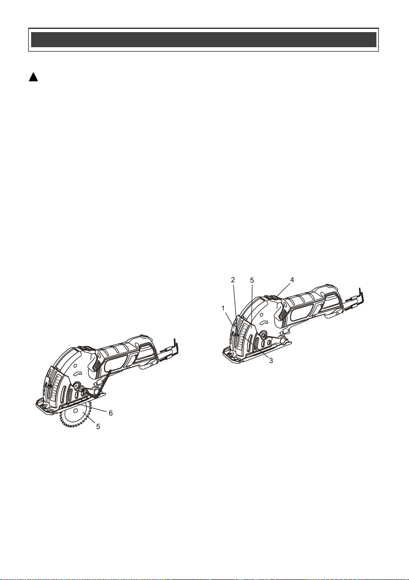
INSTALLING A BLADE
WARNING: Let the hot blade, arbor
screw and thick washer cool before
attempting to change the blade.
1. Remove the existing blade (if one is
installed), arbor screw and thick arbor
washer as noted on the previous page.
2. Slide blade (5) through the slot in the
bottom of the blade guard and onto the
arbor so the hole in the blade (6) slides
over the arbor (Fig. 2).
NOTE: Make sure the exposed teeth of a
blade with teeth are pointing forward.
3. Re-install thick arbor washer and arbor
screw in the reverse order in which they
were removed.
NOTE: Make sure the flat side of the thick
washer is facing the head of the arbor
screw.
4. Lock the spindle using the spindle lock
button and tighten the arbor screw by
turning it COUNTER CLOCKWISE.
NOTE: The arbor screw has a left hand
thread. It must be turned COUNTER
CLOCKWISE to be tightened.
ADJUSTING THE CUTTING DEPTH
The cutting depth is controlled by limiting the
amount of blade exposed below the blade
guard.
1. Loosen the depth control lever (1) by
pulling it outward (Fig. 3).
2. Slide the depth control (2) upward to the
desired cutting depth (3).
3. Lock the depth control in place by pressing
the depth control lever inward toward the
tool.
Press the rear of the blade guard lock button (4)
and carefully pivot the blade guard (5) upward
as far as it will go to expose the amount of blade
required to achieve the desired depth of cut.
NOTES:
a) The measurement markings on front of the
blade guard (3) should be used as a guide in
setting the depth of cut. This will roughly
indicate depth of cut.
b) Always set the cutting depth 1/8" greater than
the thickness of the workpiece.
c) Always test the depth setting on a scrap
workpiece to verify the setting before cutting into
the good workpiece.
INSTALLING THE EDGE GUIDE
The multi-cut saw can be used with an edge
guide for ripping materials up to 7" wide.
1. Using the 3 mm hex key provided, turn the
edge guide locking screw (1) counter
clockwise a few turns until the screw rises
about 1/8" (Fig. 4).
2. Insert the edge guide rod (2) into the left
hand edge guide mounting slot (3), through
the middle locking slot (4) and through the
right hand mounting slot (5).
ASSEMBLY AND OPERATING
!
Fig. 2
Fig. 3
16
INSTALLING THE EDGE GUIDE – cont’d
NOTE: The edge guide can be installed on
either the left or right hand side of the tool.
3. Slide the edge guide foot (6) toward the
tool until the desired width of cut is
indicated on the scale where it meets the
right hand edge of the trapezoidal window
(7).
4. Tighten the edge guide locking screw.
NOTES:
a) Do not over tighten the edge guide
locking screws or you will damage the
edge guide.
b) The edge guide scale is only an
approximate measurement. Always check
the width of cut on a scrap workpiece.
INSTALLING THE VACUUM HOSE
The vacuum adaptor and hose can be used to
attach a workshop vacuum hose to the tool. This
will prevent most cutting dust from escaping into
the work area.
1. Push the small vacuum connector (1) on
the end of the vacuum hose (2) over the
vacuum port (3) on the right hand side of
the tool (Fig. 5).
2. Twist and push the vacuum connector to
lock it into position.
3. Connect a workshop vacuum hose to the
opposite end of the vacuum hose.
ON/OFF SWITCH
This tool has dual purpose ON/OFF switch that
is designed to prevent accidental starting of the
tool. It also automatically turns the tool OFF
when the switch is not held in the ON position.
ASSEMBLY AND OPERATING
Fig. 5
For safety reasons, the operator must
read the sections of this Owner’s Manual
entitled "GENERAL SAFETY
WARNINGS", "POWER TOOL SAFETY",
"SPECIFIC SAFETY RULES",
"EXTENSION CORD SAFETY" and
"SYMBOLS" before using this multi-cut
saw.
Verify the following every time the multi-
cut saw is used:
1. Correct blade is installed for the
material being cut.
2. Blade is in good condition and is
properly installed.
3. Blade guard is in place and is in
good working order.
4. Workpiece is properly secured.
5. Safety glasses, dust mask and
hearing protection are being worn.
Failure to observe these safety rules will
significantly increase the risk of injury.
WARNING
!
Fig. 4
17
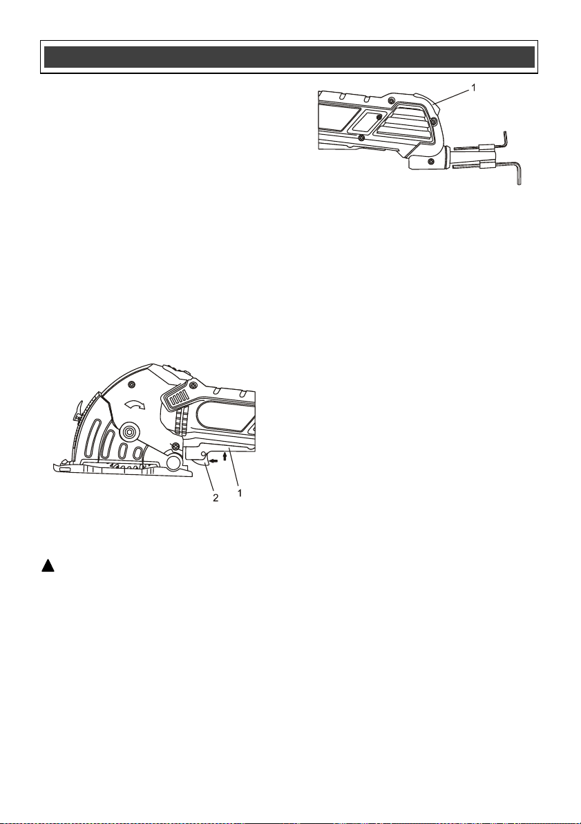
ON/OFF SWITCH – cont’d
1. To turn the multi-cut saw ON, slide your
index finger forward on the trigger switch
(1) until it moves the lock-off trigger (2)
forward.
2. While holding the lock-off trigger forward,
squeeze the trigger switch to start the
multi-cut saw.
NOTE: Once the multi-cut saw is up to
speed, slide your fingers back on the
trigger switch while continuing to squeeze
the trigger. The multi-cut saw will continue
to run.
3. To turn the multi-cut saw OFF, release the
switch trigger.
NOTE: Once the switch trigger has been
released to stop the tool, it will NOT restart
unless you push the lock-off trigger forward
again.
CUTTING (without the edge guide)
WARNING: Always use two hands on the
tool when cutting. This will make operation
of the tool easier and promote maximum
safety.
1. Install an appropriate cutting blade in the
tool as outlined on Page 15 Fig. 2.
2. Adjust the cutting depth as outlined on
Page 15 Fig. 3.
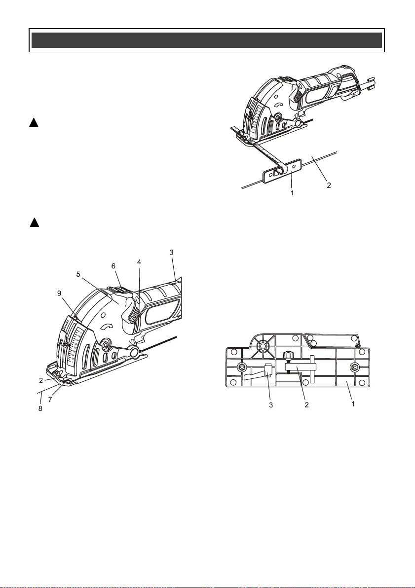
3. Plug the tool cord into the power source.
NOTE: The red "power on" light (1) on the
rear of the tool handle will illuminate when
power is "live" (Fig. 7).
4. Place leading edge of the blade guard (2)
on the workpiece to be cut (Fig. 8).
5. Grasp the tool with two hands. Place your
right hand on the body of the tool (3) being
careful not to cover the motor vents (4).
Place your left hand on the forward part of
the tool (5) so your thumb can operate the
blade guard release button (6).
6. Line up front cut line indicator (7) with the
cutting line marked on the workpiece (8).
NOTE: Do not place the blade guard too
far forward on the workpiece. This is
important to avoid the blade touching the
workpiece when the blade guard is raised
to expose the blade as outlined in
instruction # 8.
7. Turn switch ON as outlined in Fig. 6 above.
NOTE: Do not proceed any further until the
blade is running at full speed.
8. Using the thumb on your left hand, press
the blade guard release button (6) Page 18
Fig. 8.
9. Gently press downward on the front of the
tool to raise the blade guard until it touches
the depth control stop (9).
10. Re-check the alignment of the front cut line
indicator (7) and the cutting line marked on
the workpiece (8).
11. Slowly move the tool forward until the
blade touches the workpiece and begins to
cut at the cutting line.
ASSEMBLY AND OPERATING
Fig. 6
!
Fig. 7
18
CUTTING (without the edge guide)
NOTE: Feed the blade into the workpiece at a
slow steady pace. Do not force the tool so the
motor slows down. The blade will cut faster and
cleaner when turning at full speed.
WARNING: Never try to cut a curve. This
tool is designed only for straight line cuts.
Attempting to cut curves will damage the
blade, make rough cuts and possible break
the blade. Serious injury may result.
When the cut is completed, release the ON/OFF
trigger switch and wait for the blade to come to
a complete stop before removing the tool from
the workpiece.
WARNING: Make sure the blade guard
returns to its normal position covering the
blade before taking your hands off the tool.
CUTTING (with the edge guide)
To cut using the edge guide, follow the same
basic principles as noted in Paragraphs 1
through 8 above. Instead of following a cutting
line, you will simply set the edge guide at the
appropriate width and hold the guide shoe (1)
against the edge of the workpiece (2) to guide
the blade in a straight line (Fig. 9).
ASSEMBLING THE CUTTING & MITER GUIDE
The cutting & miter guide helps you make
accurate cross cuts and miter cuts with ease.
1. Turn the cutting & miter guide (1) up side
down and remove the hold-down clamp
assembly (2) and the miter clamping lever
(3) (Fig. 10).
NOTE: Both accessories are held in place
by friction-fit clamps.
2. Turn the cutting & miter guide upright and
set it on a suitable workbench or table.
3. Remove the shipping wing nut (4) and
thread the miter adjusting lever (3) onto the
threaded bolt.
NOTE: Leave the flat washer (5) on the
threaded bolt.
!
!
Fig. 10
ASSEMBLY AND OPERATING
Fig. 8
Fig. 9
19
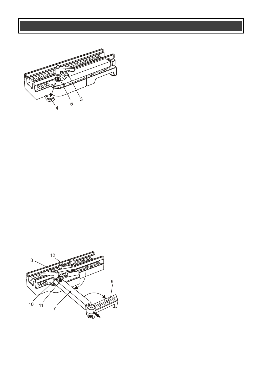
ASSEMBLING THE CUTTING & MITER GUIDE
– cont’d
4. Rotate the inner support arm (7) away from
the main housing approximately 90° and
lock it in place by turning the miter
adjusting lever clockwise.
NOTE: The miter adjusting lever can be
repositioned by pressing on the spring
loaded button (8) in the top of the lever
(Fig. 12).
5. Rotate the outer support arm (9) so it is
pointing toward the operator and is parallel
with the main housing.
NOTE: The inner support arm is
telescoping to allow the outer support arm
to be moved outward to support longer
workpieces.
6. Insert the hold-down clamp pin (10) into the
hole (11) in the support arm, then slide the
hole of the hold-down cross bar (12) onto
the hold-down clamp pin.
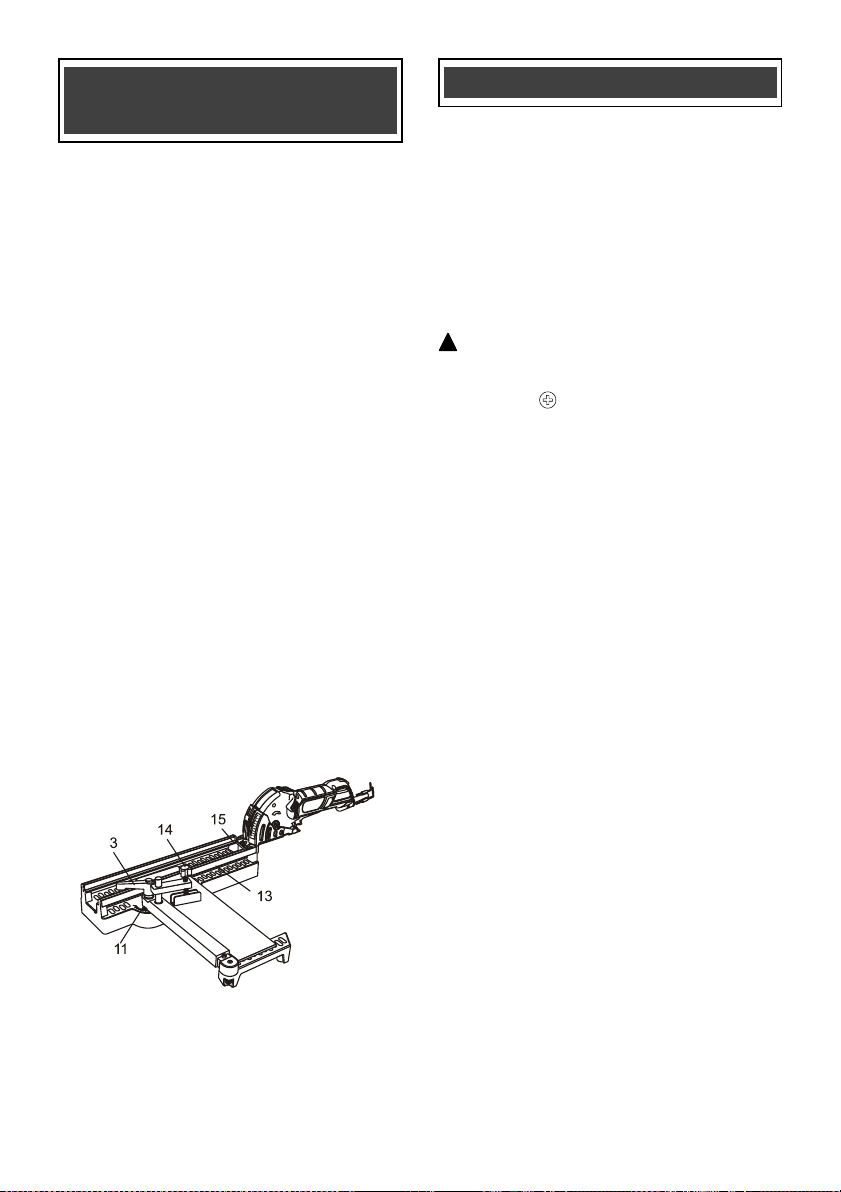
CUTTING WITH THE CUTTING & MITER
GUIDE
1. Assemble the cutting & miter guide as
outlined in Fig. 10, 11 & 12.
2. Loosen the miter adjusting lever (3) by
turning it counter clockwise (Fig. 13).
3. Rotate the inner support arm to the
appropriate angle (11) and tighten the miter
adjusting lever.
NOTE: If the lever interferes with the hold-
down clamp, press the button in the centre
of the lever and rotate it to a better
position.
4. Mark a scrap workpiece with the
appropriate angle. Place it against the
inner support arm and resting on the outer
support arm.
NOTE: The inner support arm is
telescoping and can be pulled out to
support a longer workpiece.
5. Slide the scrap workpiece under the guide
rail (13) while holding it against the support
arm until the cutting line is approximately
3/4" inside the guide rail.
6. Install the hold-down clamp knob and
position it where it will hold the workpiece
in place, then clamp the scrap workpiece to
the support arm by turning the hold-down
clamp knob (14) clockwise.
NOTE: Do not over tighten. You will break
the support arm.
7. Set the cutting depth on the multi-cut saw
to the maximum depth.
8. Slide the blade guard into the matching
grooves (15) in the cutting & miter guide
until the cut line indicator in the blade
guard is centered over the cutting mark on
the scrap workpiece.
NOTE: If the cutting mark does not appear
in the centre of the cut line indicator,
loosen the hold-down clamp and reposition
the scrap workpiece accordingly.
ASSEMBLY AND OPERATING
Fig. 12
Fig. 11
20
CUTTING WITH THE CUTTING & MITER
GUIDE – cont’d
9. Once the workpiece is properly clamped in
the cutting & miter guide, slide the blade
guard into the matching grooves in the
cutting & miter guide until the front edge of
the blade guard is even with the workpiece.
NOTE: Make sure blade will not contact
the workpiece when the blade guard is
retracted.
10. While holding the workpiece with your left
hand, turn the multi-cut saw ON, press the
tool downward to retract the blade guard
and then slide the tool forward until the
workpiece is cut.
11. When the cut is complete, turn the multi-cut
saw OFF and allow the blade to come to a
complete stop before removing the tool
from the miter guide slots.
12. Remove the scrap workpiece from the
cutting & miter guide and check both the
cutting angle and the position of the cut
relative to the cutting mark.
NOTE: Make appropriate adjustments in
the miter angle and the positioning of the
workpiece in the cutting & miter guide, then
make another test cut in the scrap
workpiece until the set-up is completely
accurate.
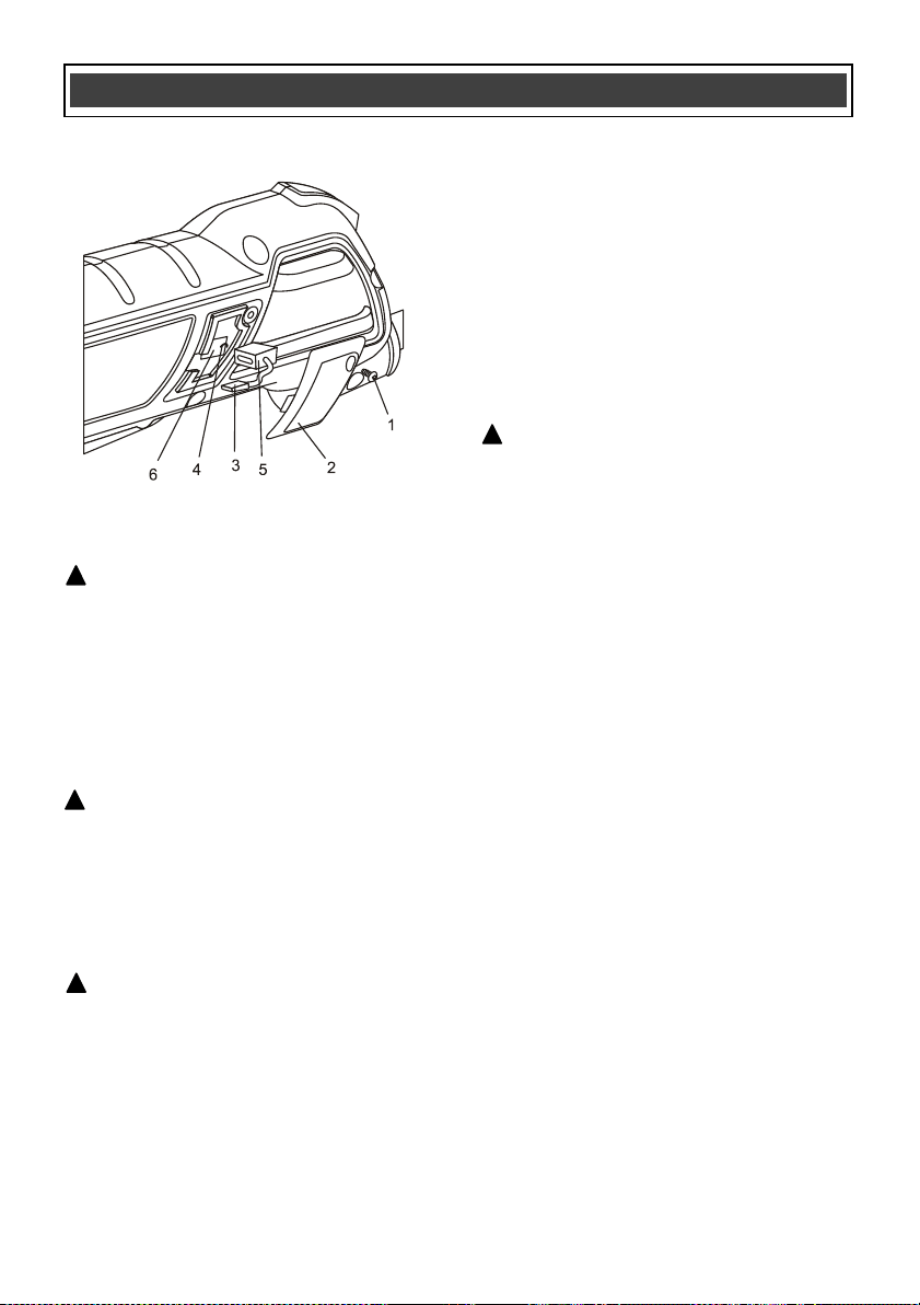
REPLACING CARBON MOTOR BRUSHES
The carbon motor brushes will wear down and
require replacing. The time intervals between
replacements will vary depending upon the type
of materials being cut and the hours of use. It is
recommended that the brushes be checked
after each 10 hours of use. When the length of
the carbon brush reaches 1/4" (6.35 mm), the
brushes should be replaced.
WARNING: Unplug the tool from the power
source.
1. Use a #1 screwdriver and remove the
screw (1) from the brush cover (2) in the
left handle (Fig. 14).
2. Use a small slot screwdriver and carefully
pry the brush cover out of the handle.
3. Use needle nose pliers and pull the outer
spade connector (3) off the inner spade
connector.
4. Use needle nose pliers to carefully lift the
brush spring (4) off the carbon brush (5).
5. Pull the carbon brush from the brush holder
(6).
6. Insert the new brush assembly into the
motor housing.
7. Reconnect the spade connector and place
the brush spring on top of the carbon brush
to hold it in place.
8. Reinstall the brush cover and brush cover
screw into the tool handle.
9. Repeat the above process and replace the
carbon brush on the opposite side of the
tool.
ASSEMBLY AND
OPERATING
Fig. 13
MAINTENANCE
!
Fig. 13
21
REPLACING CARBON MOTOR BRUSHES –
cont’d
GENERAL
WARNING: When servicing, use only
identical replacement parts. The use of any
other part may create a hazard or cause
product damage.
DO NOT use solvents when cleaning plastic
parts. Plastics are susceptible to damage from
various types of commercial solvents and may
be damaged by their use. Use a clean cloth to
remove dirt, dust, oil, grease etc.
WARNING: Do not allow brake fluids,
gasoline, petroleum-based products,
penetrating oils, etc. to come into contact
with plastic parts. They contain chemicals
that can damage, weaken or destroy plastic.
DO NOT abuse power tools. Abusive practices
can damage the tool and the workpiece.
WARNING: DO NOT attempt to modify
tools or create accessories. Any such
alteration or modification is misuse and
could result in a hazardous condition leading
to possible serious injury. It will also void
the warranty.
It has been found that electric tools are
subjected to accelerated wear and possible
premature failure when they are used on
fiberglass boats and sports cars, wallboard,
spackling compounds or plaster. The chips and
grindings from these materials are highly
abrasive to electric tool parts such as bearings,
brushes, commutators, etc. Consequently, it is
not recommended that this tool be used for
extended work on any fiberglass material,
wallboard, spackling compounds or plaster.
During any use on these materials it is
extremely important that the tool is cleaned
frequently by blowing it out with an air jet.
WARNING: Always wear safety goggles
or safety glasses with side shields during all
cutting operations. It is critical that you also
wear safety goggles or safety glasses with
side shields and a dust mask while blowing
dust out of the circular saw with an air jet.
Failure to take these safety precautions
could result in permanent eye or lung
damage.
LUBRICATION
All of the bearings in this tool are lubricated with
a sufficient amount of high-grade lubricant for
the life of the unit under normal conditions.
Therefore, no further lubrication is required.
MAINTENANCE
Fig. 14
!
!
!
!
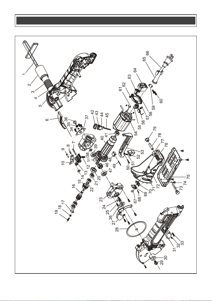
22
EXPLODED VIEW – MULTI-CUT SAW
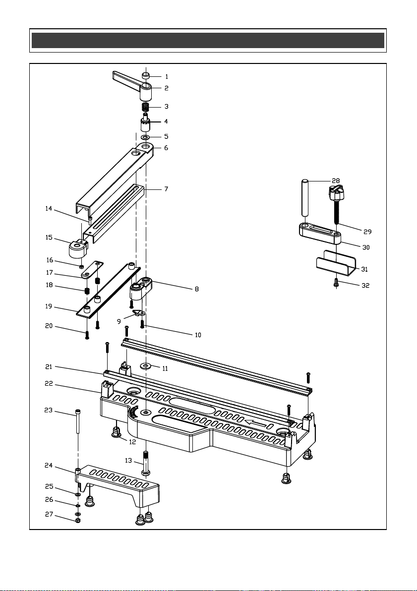
23
EXPLODED VIEW – CUTTING & MITER GUIDE

24
WARNING: When servicing, use only original equipment replacement parts. The
use of any other parts may create a safety hazard or cause damage to the multi-cut saw or
cutting & miter guide.
Any attempt to repair or replace electrical parts on this multi-cut saw or cutting & miter
guide may create a safety hazard unless repairs are performed by a qualified technician.
For more information, call the Toll-free Helpline, at 1-866-349-8665 Monday – Friday from
9am to 5pm Eastern Standard Time.
Always order by PART NUMBER, not by key number.
Key #
Part #
Part Name
Quantity
1
6220040015
Edge guide
1
2
3180040107
Vacuum adaptor
1
3
3180040106
Hose
1
4
3180040105
Hose connector
1
5
3011120007
Right housing
1
6
2020060016
Limiting plate
1
7
2040160149
Pin, dia. 4X28
1
8
2040160148
Knurled pin, dia. 4X10
1
9
4020010053
Screw M4X14
2
10
2040250011
Stop lever
1
11
0212000011
Joint washer
1
12
4100020001
Closing ring 9
1
13
2050060169
Spring
1
14
3120060043
Cage knob
1
15
4040020013
Wave washer
5
16
2010050032
Gear
6
17
2040040038
Worm
1
18
2030160074
Textile board
1
19
4040030001
Elastic washer
1
20
4020020010
Tapping screw M4X10
1
21
4010010105
Bearing 609-2RS
1
22
4010010076
Bearing 606-2RS
4
23
2020020014
Bottom worm gear case
1
24
4120020007
Woodruff key
1
25
4020010050
Screw M4X20
4
26
2040040037
Worm wheel shaft
1
27
2030130035
Inner guard
1
28
6070040003
Saw bit 36
1
29
4050050009
Blade retaining screw
1
30
2030020309
Blade claping plate
1
31
3160040073
Carbon brush cap
2
32
4030010023
Tapping screw ST2.9X8
2
33
4030010106
Tapping screw ST3.9X19
11
34
5050060108
Retaining ring
1
PARTS LIST – MULTI-CUT SAW
!

25
Key #
Part #
Part Name
Quantity
35
2050060109
Conical spiral spring
1
36
1160010014
Shaft lock
1
37
2030160119
Bearing hold down
1
38
4100050008
"E" ring dia. 7
1
39
4010010106
Bearing 627-2RS
1
40
0212000011
Rotor
1
41
4010010053
Bearing 607-2RS
1
42
3160060043
Upper indicator light cover
1
43
3160060045
Lower indicator light cover
1
44
4030010002
Tapping screw ST2X4,5
2
45
1220040018
Pilot lamp
1
46
2010050031
Worm wheel
1
47
4010010060
Bearing 608-2RS
1
48
3120040048
Lock block
1
49
2040160143
Pin, dia. 2X22
1
50
4090010010
Hollow rivet, dia. 2.5X20
1
51
2050060170
Spring
1
52
3120040047
Lock button
1
53
3120010069
Switch knob
1
54
0212000011
Stator
1
55
2030070044
Left brush holder
1
56
1230010118
Carbon brush
1
57
2050050035
Left brush spring
2
58
3150150024
Brush holder support
1
59
2030050002
Cord clamp
1
60
4030010099
Tapping Screw ST3.9X10
1
61
4030010006
Tapping screw ST2X6
1
62
2050050036
Right brush spring
1
63
2030070045
Right brush holder
1
64
1062020001
Switch
1
65
3140010072
Cord guard
1
66
2030050002
Plug & Cord
1
67
4020080016
Hex screw M4X10
1
68
2040160025
Knurled pin, dia. 2.2X12
1
69
3120120113
Depth lock lever
1
70
3120120112
Depth indicator
1
71
3120120111
Depth slipping block
1
72
2040160147
Pin
1
73
4020010127
Fixing screw
1
74
4020020001
Screw M4X8
4
75
2030010052
Base plate
1
76
2050050025
Torsion spring
1
77
2020080037
V-Guard
1
78
2010080101
Torsion spring shaft
1
79
2010210018
Side screw
1
PARTS LIST – MULTI-CUT SAW

26
Key #
Part #
Part Name
Quantity
1
3120020116
Lock nut button
1
2
3120100045
Lock lever
1
3
2050040049
Spring
1
4
1160030064
Lock nut
1
5
4040010039
Flat washer
1
6
3120040049
Inner support arm
1
7
2030250011
Extension arm
1
8
2020140006
Support block
1
9
3160060044
Angle indicator
1
10
4030010217
Tapping screw ST3.9X10
1
11
4040010011
Flat washer
1
12
3140090017
Rubber foot
9
13
4050010039
Hex bolt M8X44
1
14
4020080024
Hex screw M4X12
1
15
3120040051
End cover of extension arm
1
16
4060010005
Hex nut M4
1
17
2030250012
Clamping plate
1
18
2050040050
Spring
2
19
3120040050
Lower cover of inner support arm
1
20
4030010099
Tapping screw ST3.9X14
6
21
2020140005
Rail
2
22
3150120068
Base
1
23
4020080043
Hex screw M5x45
1
24
3150160159
Outer support arm
1
25
4040010011
Flat washer
2
26
4040020014
Wave washer
1
27
1160030065
Nut M5
1
28
2040160151
Hold-down clamp pin
1
29
1160020039
Hold-down clamp knob
1
30
2020140007
Hold-down cross bar
1
31
2030030202
Hold-down cross clamp
1
32
4030010006
Screw M4X12
1
PARTS LIST – CUTTING & MITER GUIDE

27
Rev 1.4 19/04/2018
PERFORMAX
®
MULTI-CUT SAW WARRANTY
30-DAY MONEY BACK GUARANTEE:
This PERFORMAX
®
brand power tool carries our 30-Day Money Back
Guarantee. If you are not completely satisfied with your PERFORMAX
®
brand
power tool for any reason within thirty (30) days from the date of purchase, return
the tool with your original receipt to any MENARDS
®
retail store, and we will
provide you a refund – no questions asked.
2-YEAR LIMITED WARRANTY:
This PERFORMAX
®
brand power tool carries a 2-Year Limited Warranty to the
original purchaser. If, during normal use, this PERFORMAX
®
power tool breaks
or fails due to a defect in material or workmanship within two (2) years from the
date of original purchase, simply bring this tool with the original sales receipt
back to your nearest MENARDS® retail store. At its discretion, PERFORMAX
®
agrees to have the tool or any defective part(s) repaired or replaced with the
same or similar PERFORMAX
®
product or part free of charge, within the stated
warranty period, when returned by the original purchaser with original sales
receipt. Not withstanding the foregoing, this limited warranty does not cover any
damage that has resulted from abuse or misuse of the Merchandise. This
warranty: (1) excludes expendable parts including but not limited to blades,
brushes, belts, bits, light bulbs, and/or batteries; (2) shall be void if this tool is
used for commercial and/or rental purposes; and (3) does not cover any losses,
injuries to persons/property or costs. This warranty does give you specific legal
rights and you may have other rights, which vary from state to state. Be careful,
tools are dangerous if improperly used or maintained. Seller’s employees are
not qualified to advise you on the use of this Merchandise. Any oral
representation(s) made will not be binding on seller or its employees. The rights
under this limited warranty are to the original purchaser of the Merchandise and
may not be transferred to any subsequent owner. This limited warranty is in lieu
of all warranties, expressed or implied including warranties or merchantability
and fitness for a particular purpose. Seller shall not be liable for any special,
incidental, or consequential damages. The sole exclusive remedy against the
seller will be for the replacement of any defects as provided herein, as long as
the seller is willing or able to replace this product or is willing to refund the
purchase price as provided above. For insurance purposes, seller is not allowed
to demonstrate any of these power tools for you.
For questions / comments, technical assistance or repair parts –
Please Call Toll Free at: 1-866-349-8665 (M-F 8am – 6pm)
SAVE YOUR RECEIPTS. THIS WARRANTY IS VOID WITHOUT THEM.
Distributed by: Menard, Inc., Eau Claire, WI 54703