
ASSEMBLY MANUAL / OWNER’S MANUAL
This product is compliant with the
applicable CE requirements.

2
Important Safety Instructions 3
Safety Warning Labels / Serial Number 5
Earthing Instructions 6
Specications 7
BeforeAssembly 7
Parts 8
Hardware 9
Tools 9
Assembly 10
Moving the Machine 22
Leveling the Machine 23
Features 24
Console Features 25
Bluetooth
®
Connectivity 28
Remote Heart Rate Monitor 29
Operations 31
Power Up / Idle Mode 31
Initial Setup 32
Quick Start Program 32
UserProles 32
ProlePrograms 34
Pausing or Stopping 38
Results / Cool Down Mode 38
GOAL TRACK Statistics 38
Console Setup Mode 40
Maintenance 41
Maintenance Parts 42
Troubleshooting 44
TABLE OF CONTENTS
To validate warranty support, keep the original proof of purchase and record the following information:
Serial Number __________________________
Date of Purchase ____________________
To register your product warranty, contact your local distributor.
For details regarding product warranty or if you have questions or problems with your product, please contact
yourlocalNautilusdistributor.Tondyourlocaldistributor,goto:www.nautilusinternational.com
Nautilus,Inc.,www.nautilusinternational.com|Nautilus,Inc.,18225NERiversideParkway,Portland,OR97230USA|Printedin
China | © 2016 Nautilus, Inc. | ® indicates trademarks registered in the United States. These marks may be registered in other
nationsorotherwiseprotectedbycommonlaw.Schwinn,theSchwinnQualitylogo,Schwinn570E,SchwinnConnect,Bowex,
Nautilus, and Universal are trademarks owned by or licensed to Nautilus, Inc. Polar
®
, OwnCode
®
, Loctite
®
, iTunes
®
, Under
Armour
®
, and MyFitnessPal
®
are trademarks of their respective owners. The Bluetooth
®
word mark and logos are registered
trademarks owned by Bluetooth SIG, Inc., and any use of such marks by Nautilus, Inc. is under license.
ORIGINAL MANUAL - ENGLISH VERSION ONLY

3
When using an electrical appliance, basic precautions should always be followed, including the following:
This icon means a potentially hazardous situation which, if not avoided, could result in death or serious
injury.
Obey the following warnings:
Read and understand all warnings on this machine.
Carefully read and understand the Assembly instructions. Read and understand the complete
Manual. Keep the Manual for future reference.
To reduce the risk of electrical shock or unsupervised usage of the equipment, always unplug this
machine from the electrical outlet immediately after using and before cleaning.
To decrease the risk of burns, electric shock, or injury to persons, read and understand the com-
plete Owner’s Manual. Failure to follow these guidelines can cause a serious or possibly fatal electrical shock or
other serious injury.
• Keep bystanders and children away from the product you are assembling at all times.
• Do not connect power supply to the machine until instructed to do so.
• The machine should never be left unattended when plugged in. Unplug from outlet when not in use, and before putting
on or taking off parts.
• Beforeeachuse,examinethemachinefordamagetopowercord,loosepartsorsignsofwear.Donotuseiffoundin
this condition. Contact your local distributor for repair information.
• Do not drop or put objects into any opening of the machine.
• Do not assemble this machine outdoors or in a wet or moist location.
• Makesureassemblyisdoneinanappropriateworkspaceawayfromfoottrafcandexposuretobystanders.
• Some components of the machine can be heavy or awkward. Use a second person when doing the assembly steps
involving these parts. Do not do steps that involve heavy lifting or awkward movements on your own.
• Set up this machine on a solid, level, horizontal surface.
• Do not try to change the design or functionality of this machine. This could compromise the safety of this machine and
will void the warranty.
• If replacement parts are necessary, use only genuine Nautilus replacement parts and hardware. Failure to use
genuine replacement parts can cause a risk to users, keep the machine from operating correctly and void the
warranty.
• Do not use until the machine has been fully assembled and inspected for correct performance in accordance with the
Manual.
• Use this machine only for its intended use as described in this manual. Do not use attachments not recommended by
the manufacturer.
• Do all assembly steps in the sequence given. Incorrect assembly can lead to injury or incorrect function.
• Connect this machine to a properly grounded outlet only (see Earthing Instructions).
• Keep the power cord away from heat sources and hot surfaces.
• Do no operate where aerosol products are being used.
• To disconnect, turn all controls to the off position, then remove plug from outlet.
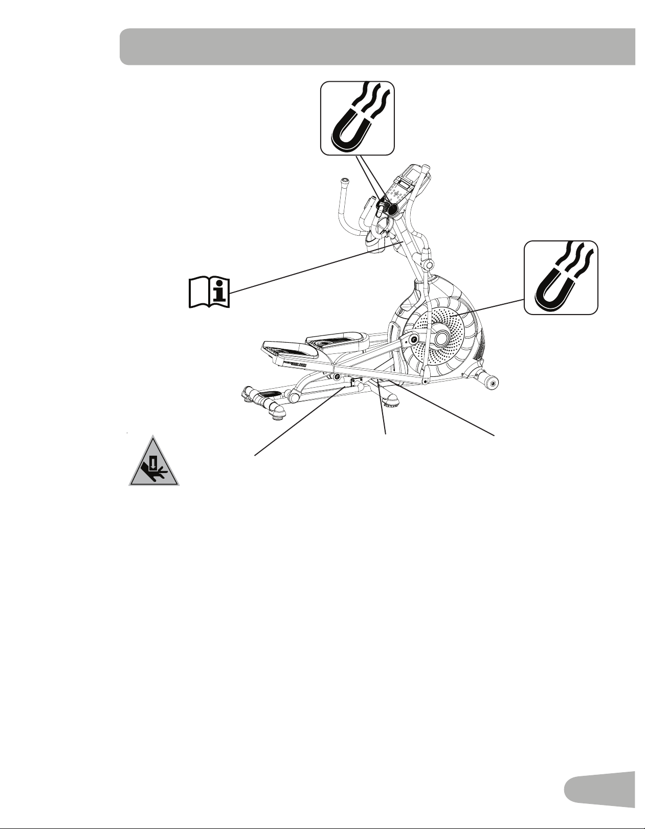
• Thisproductcontainsmagnets.Magneticeldscaninterferewiththenormaluseofcertainmedicaldevicesataclose
range.Usersmaycomeintoproximityofthemagnetsintheassembly,maintenance,and/oruseoftheproduct.Given
the obvious importance of these devices, such as a pacemaker, it is important that you consult with your medical
provider in connection with the use of this equipment. Please consult the “Safety Warning Labels and Serial Number”
section to determine the location of the magnets on this product.
• SAVE THESE INSTRUCTIONS.
IMPORTANT SAFETY INSTRUCTIONS

4
Before using this equipment, obey the following warnings:
Read and understand the complete Manual. Keep the Manual for future reference.
Read and understand all warnings on this machine. If at any time the Warning labels become loose,
unreadable or dislodged, contact your local Schwinn distributor for replacement stickers.
• Children must not be let on or near to this machine. Moving parts and other features of the machine can be dangerous
to children.
• Not intended for use by anyone under 14 years of age.
• Consultaphysicianbeforeyoustartanexerciseprogram.Stopexercisingifyoufeelpainortightnessinyour
chest, become short of breath, or feel faint. Contact your doctor before you use the machine again. Use the values
calculated or measured by the machine’s computer for reference purposes only.
• Beforeeachuse,examinethismachineforloosepartsorsignsofwear.Donotuseiffoundinthiscondition.Monitor
the Pedals and Crank Arms closely. Contact your local Schwinn distributor for repair information.
• Maximumuserweightlimit:136kg(300lbs.).Donotuseifyouareoverthisweight.
• This machine is for home use only.
• Donotwearlooseclothingorjewelry.Thismachinecontainsmovingparts.Donotputngersorotherobjectsinto
movingpartsoftheexerciseequipment.
• Set up and operate this machine on a solid, level, horizontal surface.
• Make the Foot Pedals stable before you step on them. Use caution when you step on and off the machine.
• Disconnect all power before servicing this machine.
• Do not operate this machine outdoors or in moist or wet locations.
• Keep at least 0.6 m ( 24” ) on each side of the machine clear. This is the recommended safe distance for access and
passage around and emergency dismounts from the machine. Keep third parties out of this space when machine is in
use.
• Donotoverexertyourselfduringexercise.Operatethemachineinthemannerdescribedinthismanual.
• Correctly adjust and safely engage all Positional Adjustment Devices. Make sure that the Adjustment Devices do not
hit the user.
• Keep the Foot Pedals and Handlebars clean and dry.
• Exerciseonthismachinerequirescoordinationandbalance.Besuretoanticipatethatchangesinspeedand
resistance level can occur during workouts, and be attentive in order to avoid loss of balance and possible injury.
• A machine should never be left unattended when plugged in. Unplug from outlet when not in use, and before putting
on or taking off parts.
• Use this machine only for its intended use as described in this manual. Do not use attachments not recommended by
the manufacturer.
• This appliance is not intended for use by persons (including children) with reduced physical, sensory or mental
capabilities,orlackofexperienceandknowledge,unlesstheyhavebeengivensupervisionorinstructionconcerning
use of the appliance by a person responsible for their safety.
5
SAFETY WARNING LABELS AND
SERIAL NUMBER
Serial Number
REVISIONS
ECO
REVISION
REV DESCRIPTION
APPROVED
DATE
TITLE.
PART NO.
REV.
SHEET 1 OF 1
SCALE: 1:1
DO NOT SCALE DRAWING
1. ALL ITEMS MUST BE RoHS COMPLIANT
2. ALL DIMENSIONS APPLY BEFORE PLATING OR COATING.
3. REMOVE ALL BURRS, BREAK SHARP EDGES 0.5 MM MAX.
4. ALL MACHINES SURFACES Ra 3.2 uM.
5. ALL APPLICABLE NAUTILUS STANDARDS AND
SPECIFICATIONS APPLY.
6. ALL DIMENSIONS ARE IN MILLIMETERS
7. ALL DUAL DIMENSIONS ARE IN INCH
UNLESS OTHERWISE SPECIFIED:
METRIC
THIRD ANGLE
PROJECTION
INTERPRET DIMENSIONS AND TOLERANCES
PER ASME Y14.5M - 1994
2.5
1.5
0.75
0.25
1°
X.
X.X
X.XX
X.XXX
ANGULAR
C
SIZE
This document is the property of Nautilus, Inc. It may not be reproduced in whole or part, provided to third parties, or used for any purposes other than the performance of work for Nautilus, Inc. without written authorization. All rights are reserved, including copyrights.
TOLERANCES.
DRAWN
DESIGNED
DATE
METRIC_C_REV G
NAUTILUS, INC.
16400 SE NAUTILUS DRIVE, VANCOUVER, WA 98683
LIFECYCLE
7-22-10
APPROVALS
- -
- - - -
WARRANTY ITEM:
A RELEASED
NPI 13149 DLOVELY
7-22-10
D.LOVELY
D.LOVELY
07 /22 / 2010
D.LOVELY
A
004-0930
CRUSH WARNING
21.78mm
54.8mm
MATERIAL.
COLOR.
DIE LINE
PMS 152
PMS 109
BLACK
WHITE
Labels must be created from an agency approved tamper proof labeling system
such as "UL Recognized component marking and labeling system (example: UL PGGU2) or equivalent.
Label and adhesive must be rated for surface it is applied to (painted metal or ABS plastic),
Label and adhesive must be rated for 60 degrees C minimum. Labels must meet UL 1647 Permanence of Marking Test.
•
•
ProductSpecication
WARNING!
• Keep hands and feet away.

6
Earthing Instructions
This product must be electrically earthed. If a malfunction occurs, correct earthing decreases the risk of electric shock.
The power cord is equipped with an equipment-earthing conductor, and must be connected to an outlet that is properly
installed and earthed.
The electrical wiring must comply with all applicable local and provincial standards and
requirements. Incorrect connection of the equipment-earthing conductor can result in a risk of
electric shock. Consult a licensed electrician if you are not sure that the machine is correctly
earthed. Do not change the plug on the machine – if it does not t the outlet, have a correct outlet
installed by a licensed electrician.
If you connect the machine to an outlet with RCBO (Residual-Current circuit Breaker with Overload protection), machine
operation can cause the circuit to trip. A Surge Protector Device is recommended to protect the machine.
!
If a Surge Protector Device (SPD) is used with this machine, be sure that it matches the power rating of
this equipment (220-240V AC). Do not connect other appliances or devices to the surge protector in
combination with this machine.
Make sure that the product is connected to an outlet having the same conguration as the plug. No
adapter should be used with this product.
7
SPECIFICATIONS
Before Assembly
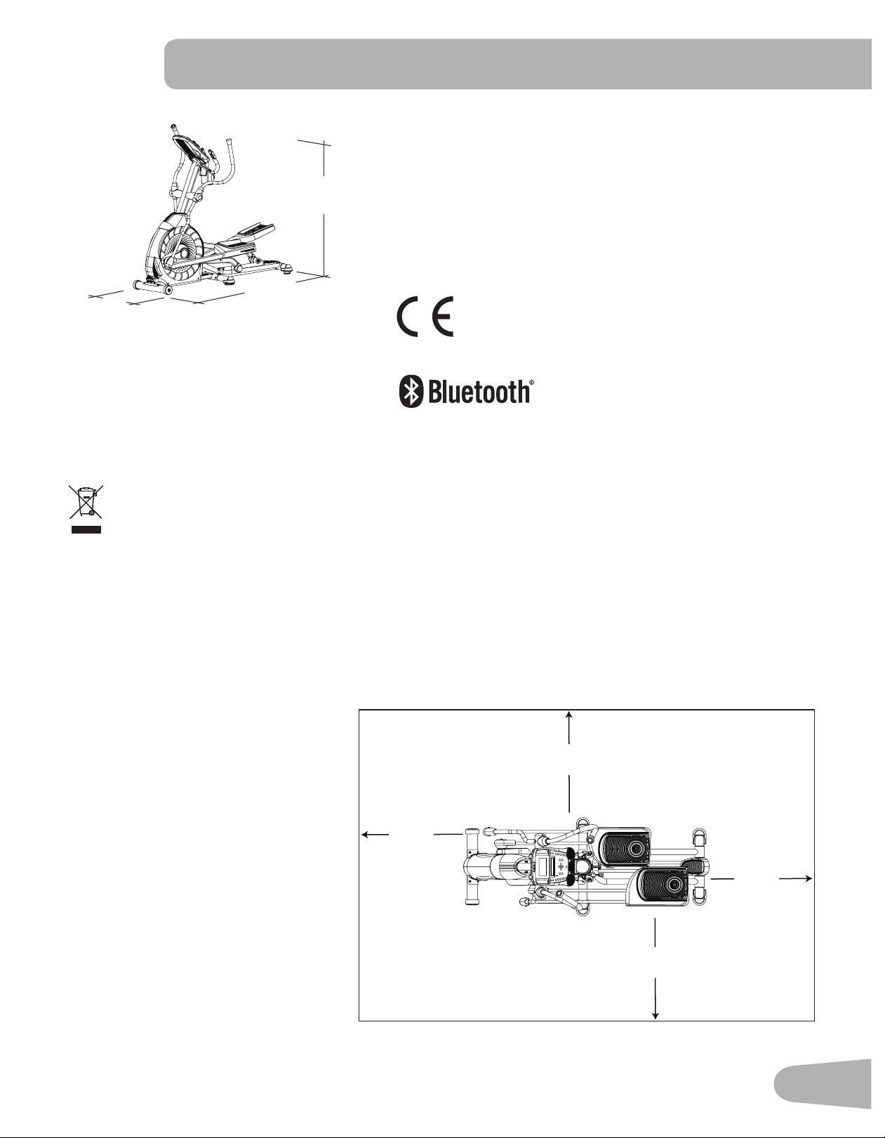
Select the area where you are going to set up and operate your machine. For safe operation, the location must be on a
hard,levelsurface.Allowaworkoutareaofaminimum193cmx305cm(76”x120”).Besurethattheworkoutspace
youareutilizinghasadequateheightclearance,takingintoconsiderationtheheightoftheuserandthemaximumincline
of the elliptical machine.
Basic Assembly Tips
Follow these basic points when you
assemble your machine:
• Read and understand the “Impor-
tant Safety Instructions” before
assembly.
• Collect all the pieces necessary for
each assembly step.
• Using the recommended wrench-
es, turn the bolts and nuts to the
right (clockwise) to tighten, and the
left (counterclockwise) to loosen,
unless instructed otherwise.
• When attaching 2 pieces, lightly
lift and look through the bolt holes
to help insert the bolt through the
holes.
• The assembly can require 2
people.
3.0m ( 118.1” )
1.93m
( 76.2” )
0.6m
( 24” )
0.6m
( 24” )
0.6m
( 24” )
0.6m
( 24” )
Maximum User Weight: 136 kg ( 300 lbs. )
Maximum Pedal Height - with full incline: 66.1 cm ( 26.0” )
Machine Weight: 76.5kg(168.7lbs.)
Total Surface Area (foot print) of equipment:
12734.2cm
2
(1976.8inches
2
)
Power Requirements:
Operational Voltage: 220V - 240V AC, 50Hz
Operating Current: 1A
Complies with the following:
ISO20957Compliant
Connectivity:
160.5 cm
( 63.2” )
178.1 cm
( 70.1” )
71.5 cm
( 28.2” )
DO NOT dispose of this product as refuse. This product is to be recycled. For proper disposal of this product,
please follow the prescribed methods at an approved waste center.
8
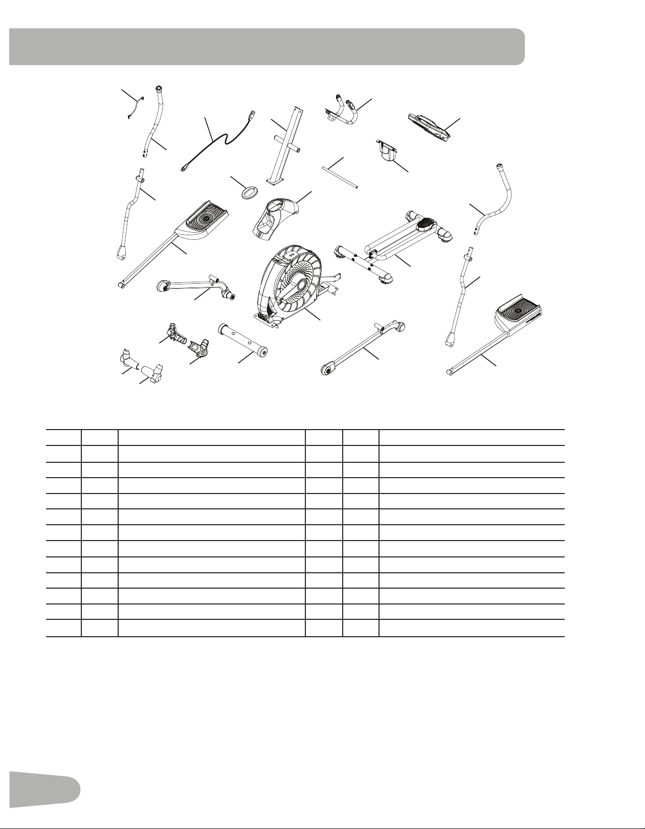
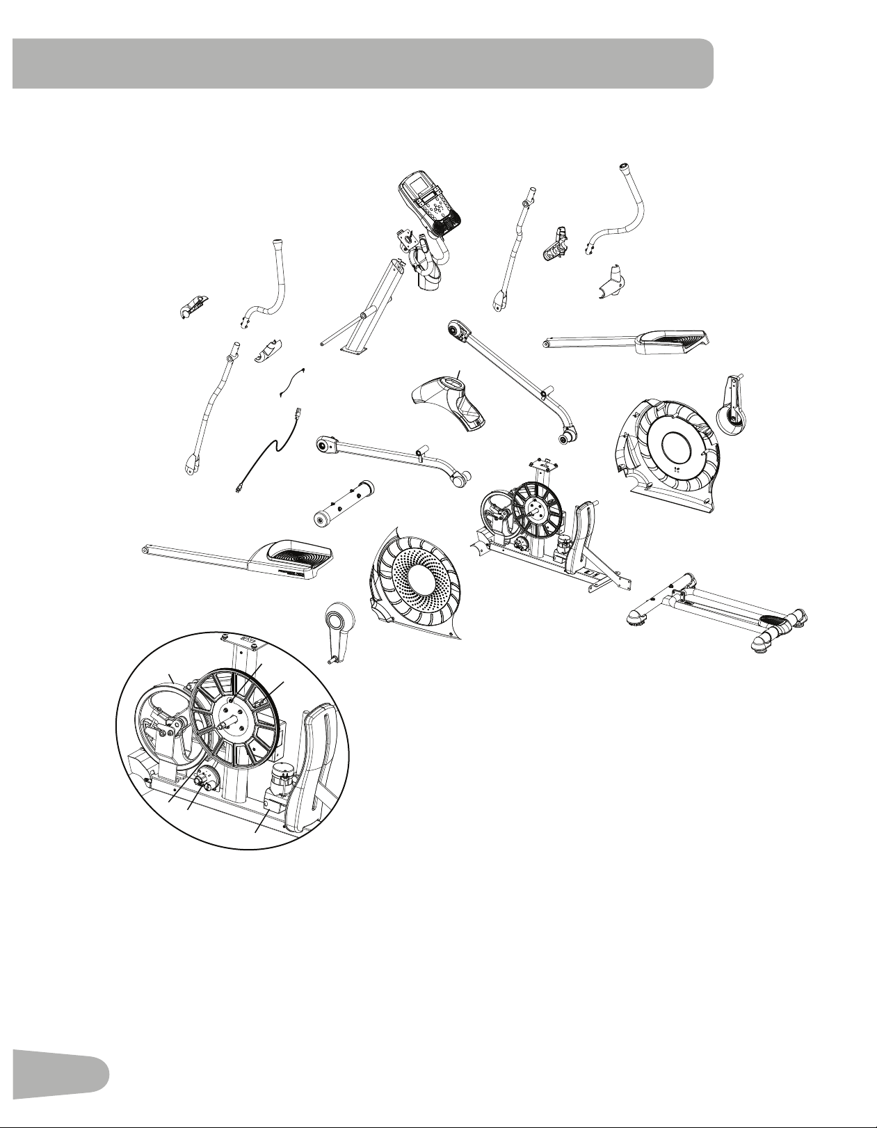
PARTS
A decal has been applied to all right (“ R ”) and left (“ L ”) parts to assist with assembly.
Item Qty Description Item Qty Description
1 1 Console Mast 13 1 Front Stabilizer
2 1 Static Handlebar 14 2 Handlebar Shroud, Inner
3 1 Arm Pivot Rod 15 2 Handlebar Shroud, Outer
4 1 Water Bottle Holder 16 1 Right Leg
5 1 Console 17 1 Right Pedal
6 1 Upper Left Handlebar Arm 18 1 Shroud Cap
7 1 Lower Left Handlebar Arm 19 1 Lower Right Handlebar Arm
8 1 Left Pedal 20 1 Upper Right Handlebar Arm
9 1 Rail Assembly 21 1 Power Cord
10 1 Left Leg 22 1 MP3 Cord
11 1 Frame 23 1 Silicone Lubricant, bottle (not shown)
12 1 Upper Shroud
1
4
6
5
2
3
12
7
8
10
11
9
18
16
13
20
19
17
15
14
15
14
21
22
9
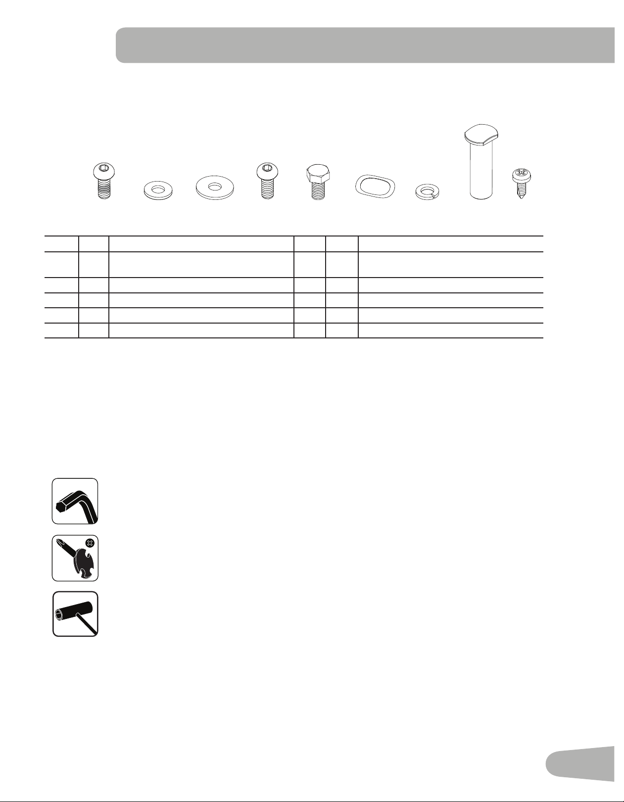
Item Qty Description Item Qty Description
A 6 ButtonHeadHexScrew,M8x16(with
Loctite
®
adhesive)
F 6 Wave Washer
B 4 Flat Washer, M8 G 12 Lock Washer, M8
C 8 Wide Washer, M8 H 2 Pivot Sleeve
D 4 ButtonHeadHexScrew,M8x16 I 4 PhillipsHeadScrew,M5x12
E 2 HexHeadScrew,M8x20
Note: Select pieces of Hardware have been provided as spares on the Hardware Card. Be aware that there may be remain-
ing Hardware after the proper assembly of your machine.
HARDWARE / TOOLS
Tools
Included
6 mm
#2
13 mm
15 mm
19 mm
A B C D E F
G H
I
10
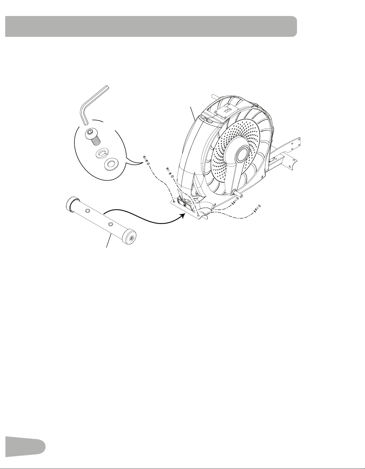
ASSEMBLY
1. Attach Front Stabilizer to Frame
Note: Hardware is pre-installed and not on the Hardware Card. *
13
11
6mm
*
*
X4
*
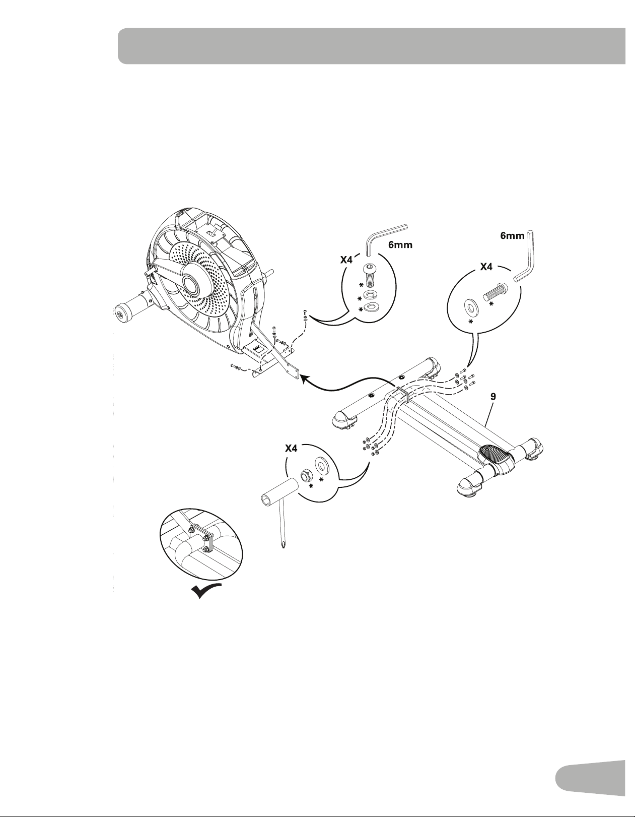
11
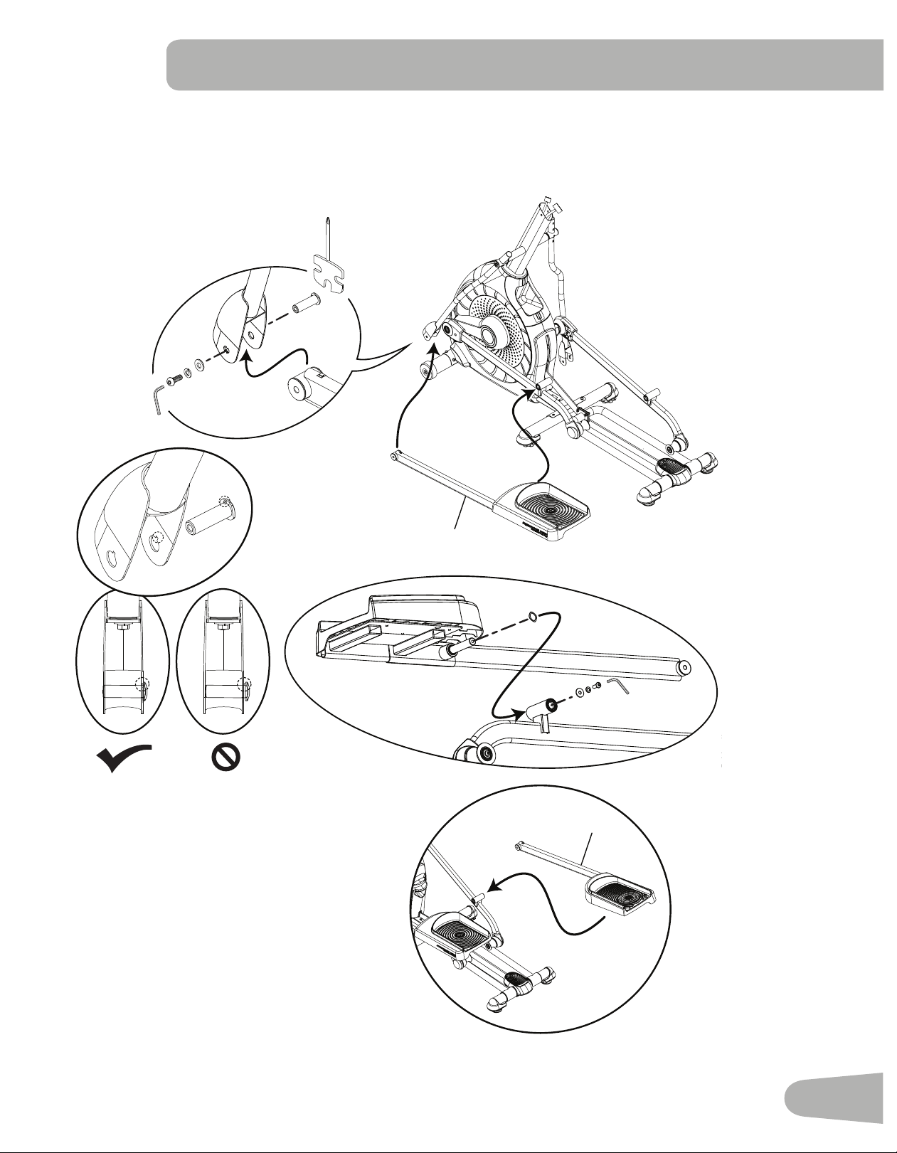
2. Attach Rail Assembly to Frame Assembly
Note: Hardware is pre-installed and not on the Hardware Card. *
12
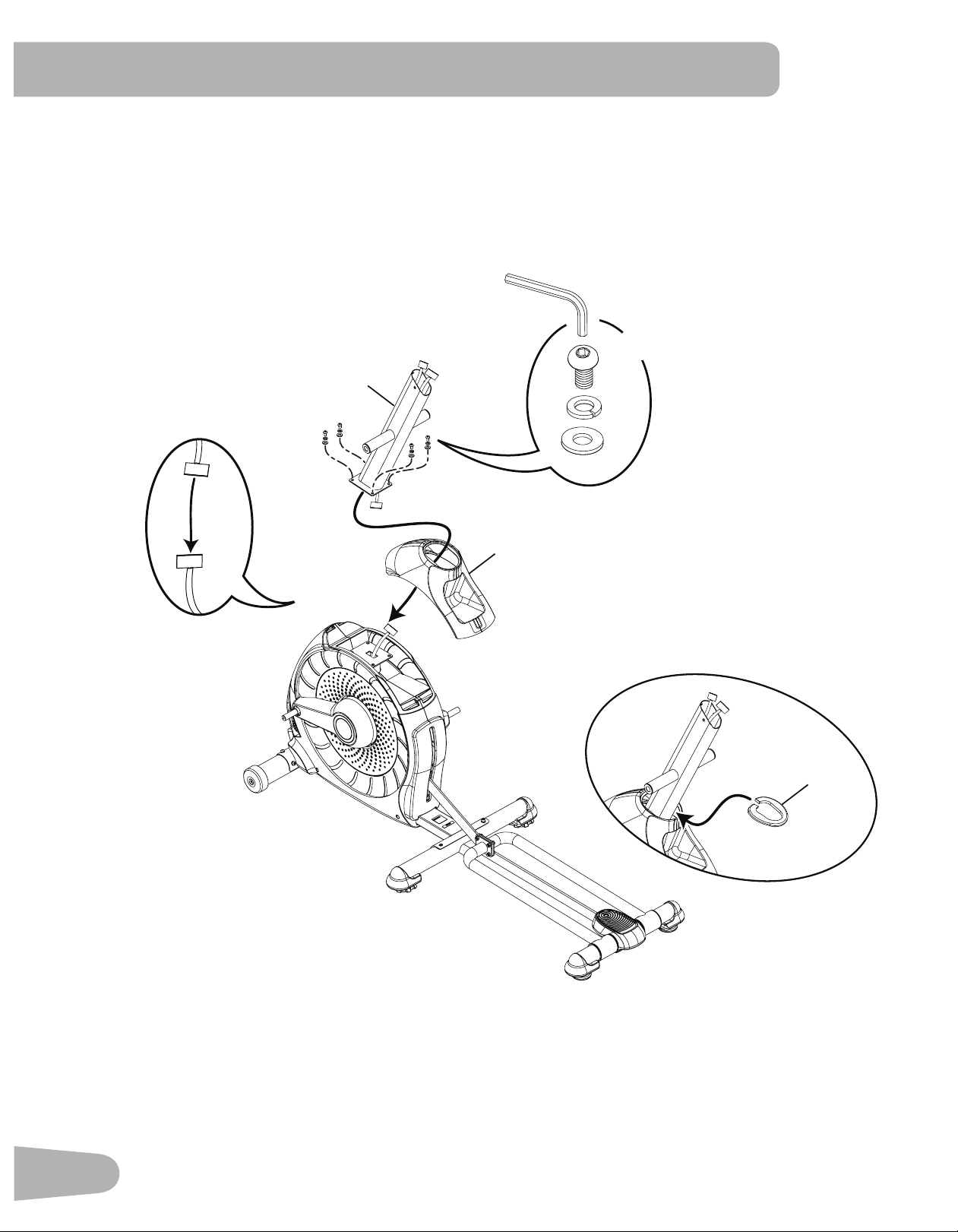
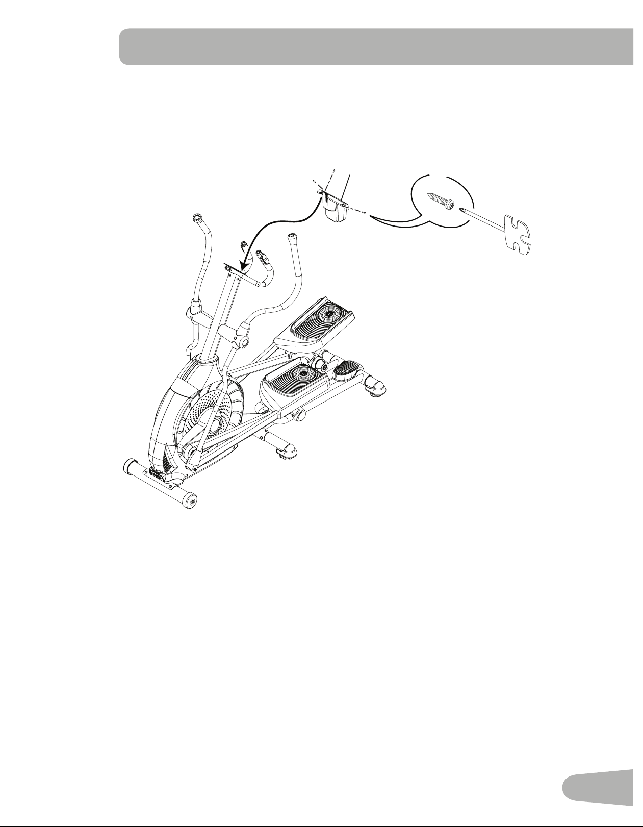
3. Connect the Cable and Attach the Console Mast to Frame Assembly
NOTICE: Do not crimp Console Cable.
18
1
12
B
D
G
6mm
X4
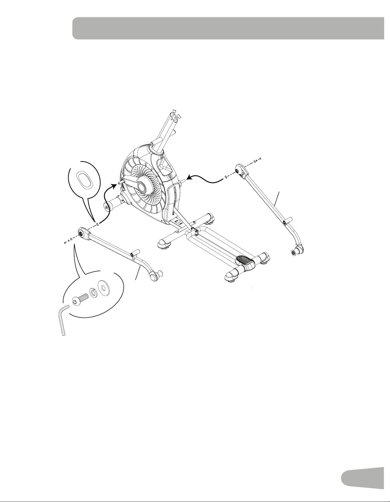
13
4. Attach Legs to Frame Assembly
10
16
A
C
G
F
X2
X2
6mm
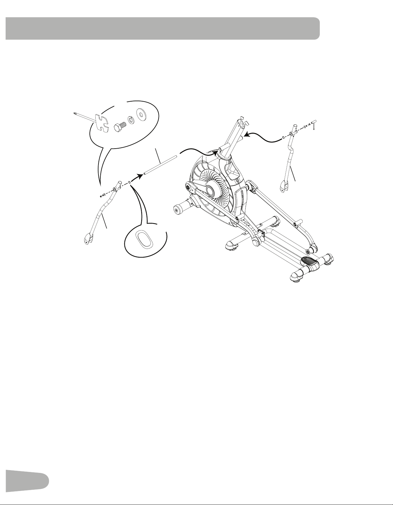
14
5. Attach Arm Pivot Rod and Lower Handlebar Arms to Frame Assembly
19
3
7
C
G
E
F
X2
X2
13 mm
15
6. Attach Left Pedal to Frame Assembly
NOTICE: RepeatsteponoppositesidewiththeRightPedal(Item17).
F
A
C
G
8
C
H
G
A
6mm
H
17
16
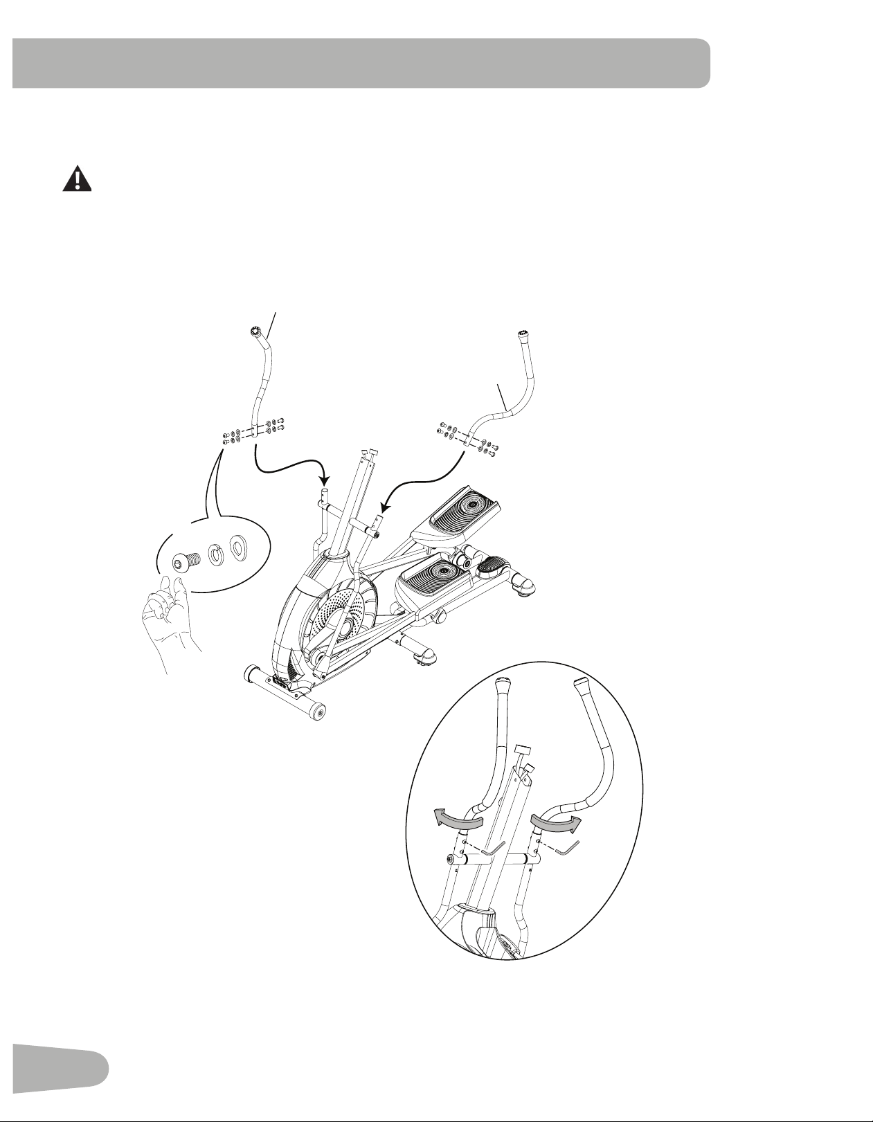
7. Attach and Adjust the Upper Handlebar Arms to Frame Assembly
Note: Hardware is pre-installed and not on the Hardware Card. *
Make sure the Upper Handlebar Arms are secure before you exercise.
6mm
20
6
*
*
*
X8
17
8. Attach Handlebar Shrouds to Frame Assembly
15
14
15
14
I
#2
X4
18
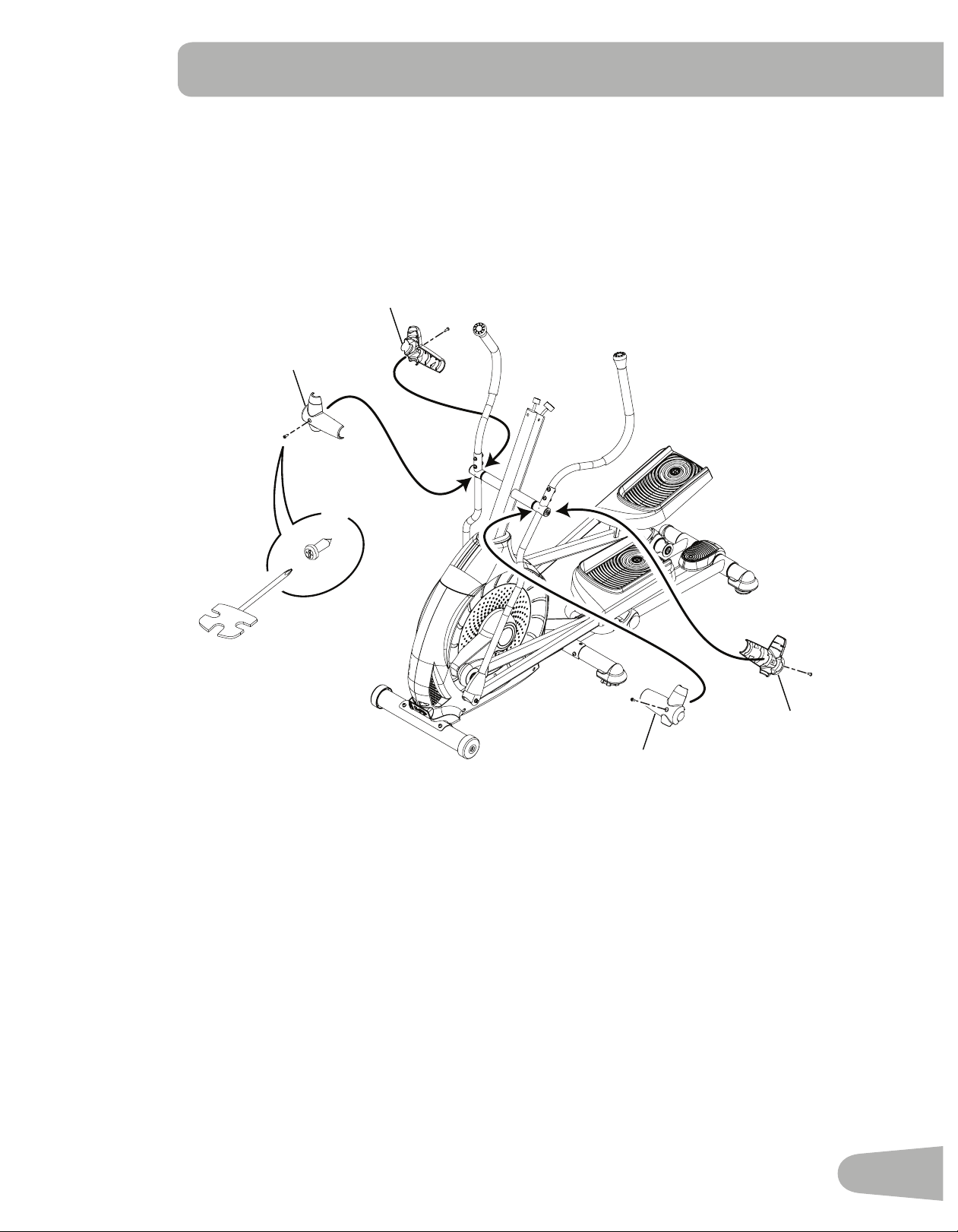
9. Route Cables and Attach the Static Handlebar to Frame Assembly
NOTICE: Do not crimp the Console Cables.
2
*
X3
6mm
*
*
19
10. Attach Water Bottle Holder to Frame Assembly
Note: Hardware is pre-installed and not on the Hardware Card. *
4
#2
*
X3
20
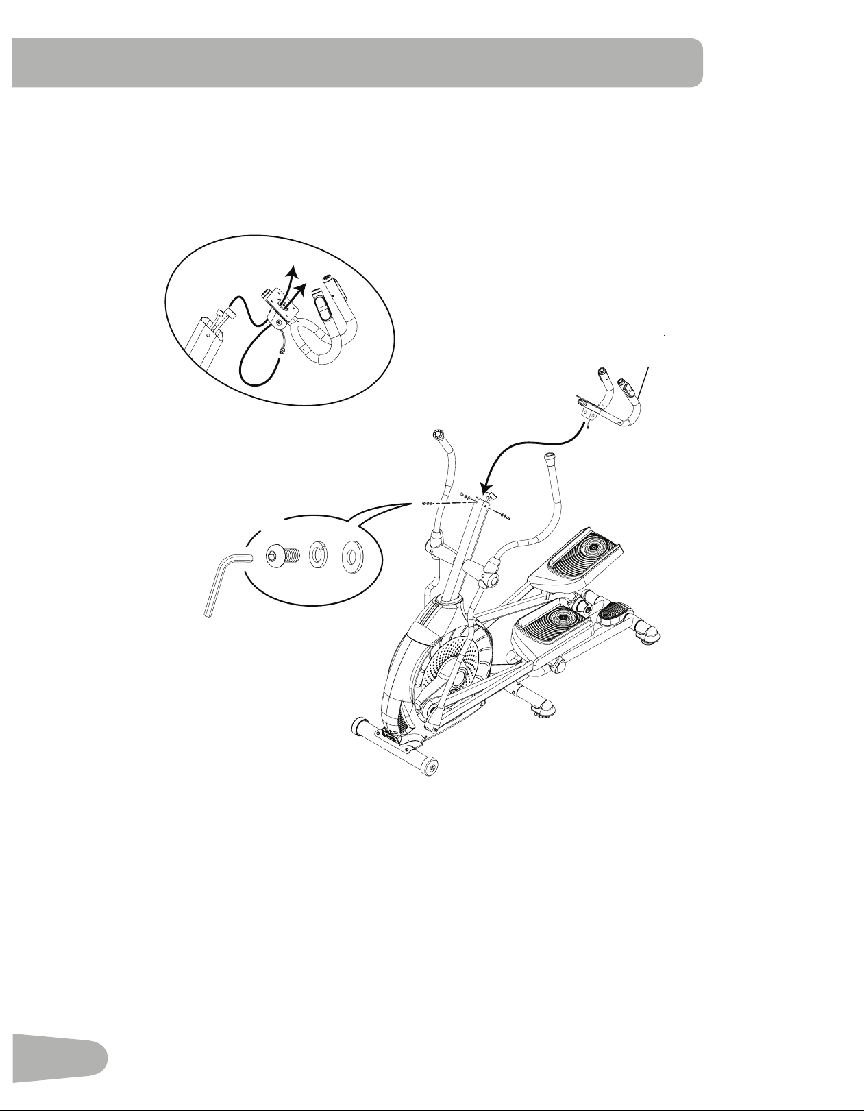
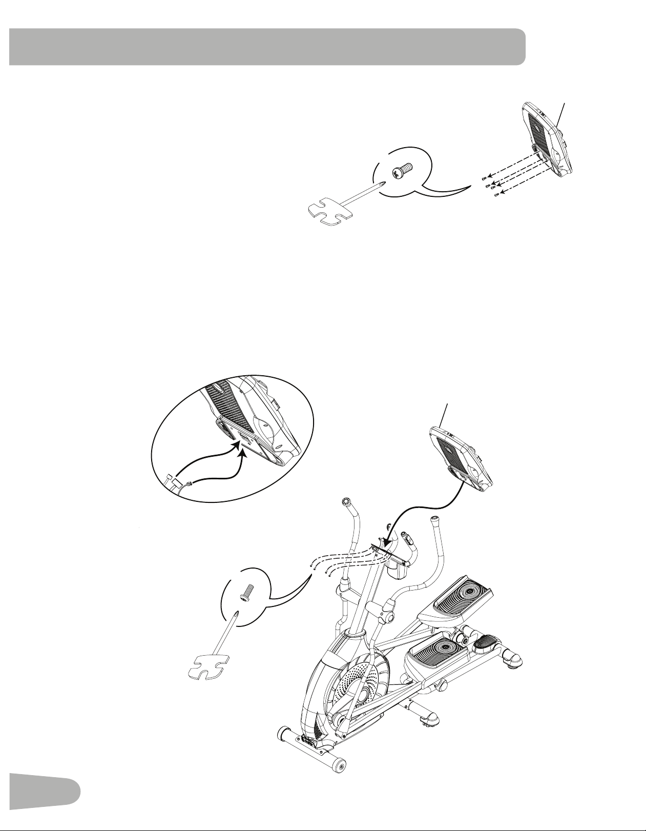
12. Connect Cables and Attach Console to Frame Assembly
NOTICE: Align the clips on the cable connectors and make sure the connectors lock. Do not crimp cables.
11. Remove Hardware from Console
NOTICE: Do not crimp the cable.
Note: Hardware is pre-installed and not on the Hardware Card. *
5
*
X4
#2
5
*
X4
21
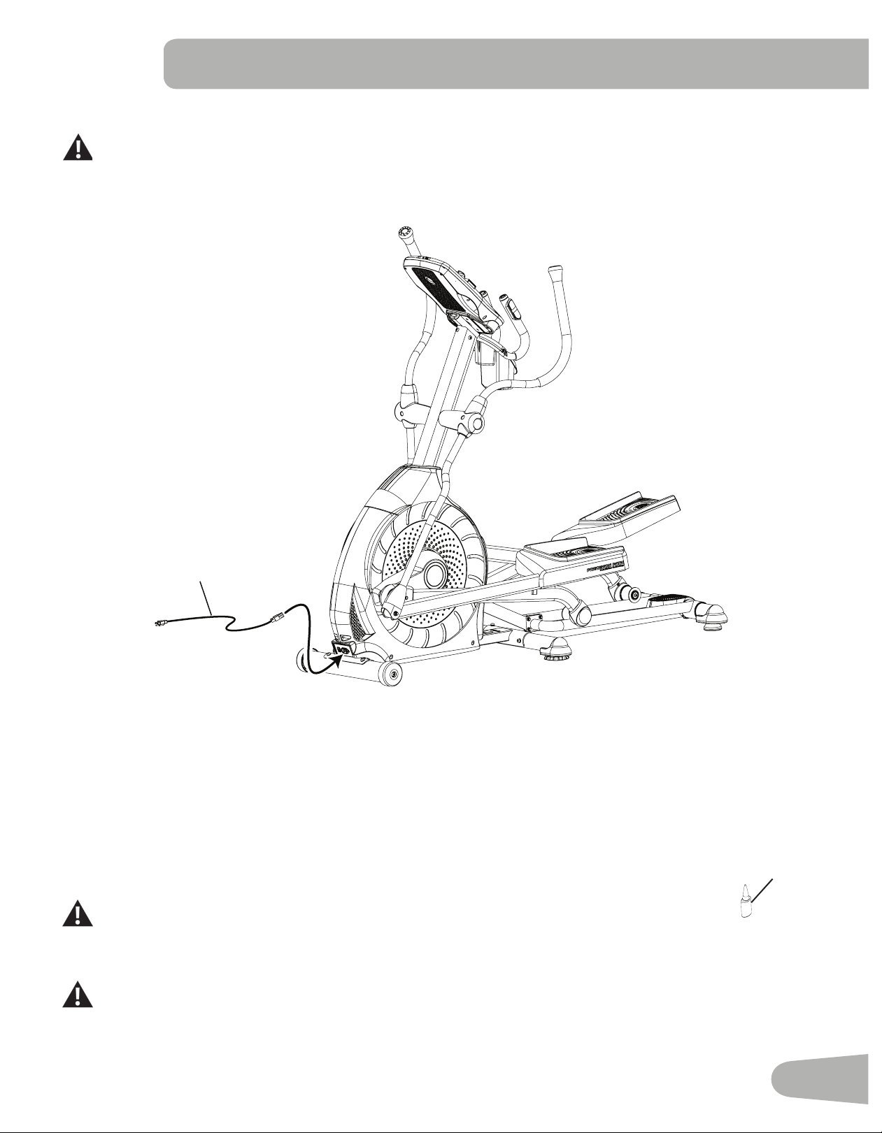
13. Connect the Power Cord to Frame Assembly
Connect this machine to a properly earthed outlet only (see Earthing Instructions).
21
14. Final Inspection
Inspect your machine to ensure that all hardware is tight and components are properly assembled.
Note: If necessary, apply silicone lubricant to a cloth and wipe the rails to eliminate roller noise.
Silicone lubricant is not intended for human consumption. Keep out of reach of children.
Store in a safe place.
Besuretorecordtheserialnumberintheeldprovidedatthefrontofthismanual.
Do not use until the machine has been fully assembled and inspected for correct performance in accor-
dance with the Owner’s Manual.
23
22
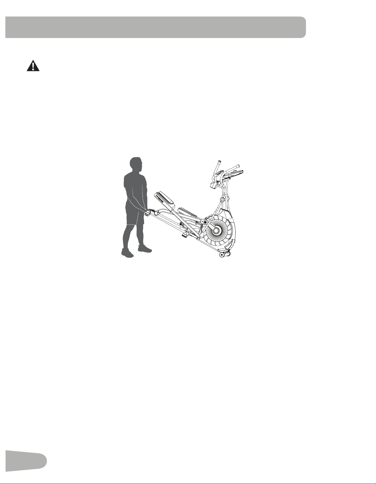
Moving the Machine
The machine may be moved by one or more persons depending on their physical abilities and capacities.
Make sure that you and others are all physically t and able to move the machine safely.
1. Remove the power cord.
2. Use the Transport Handle to carefully lift the machine onto the transport rollers.
3. Push the machine into position.
4. Carefully lower the machine into position.
NOTICE: Be careful when you move the elliptical. Abrupt motions can affect the computer operation.
BEFORE YOU START
23
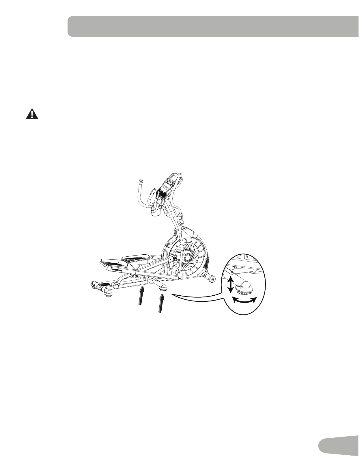
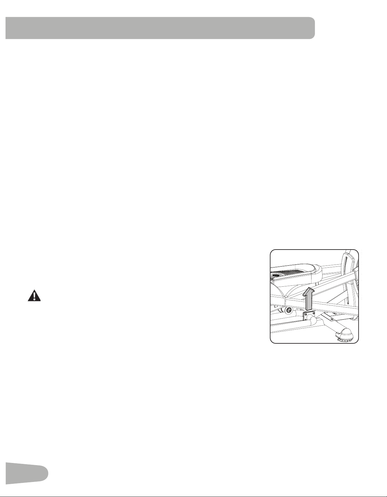
Leveling the Machine
ThemachineneedstobeleveledifyourworkoutareaisunevenoriftheRailAssemblyisslightlyofftheoor.Toadjust:
1. Place the machine in your workout area.
2. SafelystandonthebackoftheRailAssemblyforapproximately20seconds.
3. Step off the machine.
4. Loosenthelockingnutsandadjustthelevelersuntiltheyallcontacttheoor.
Do not adjust the levelers to such a height that they detach or unscrew from the machine. Injury to you or
damage to the machine can occur.
5. Adjust until the machine is level. Tighten the locking nuts.
Makesurethemachineislevelandstablebeforeyouexercise.
24
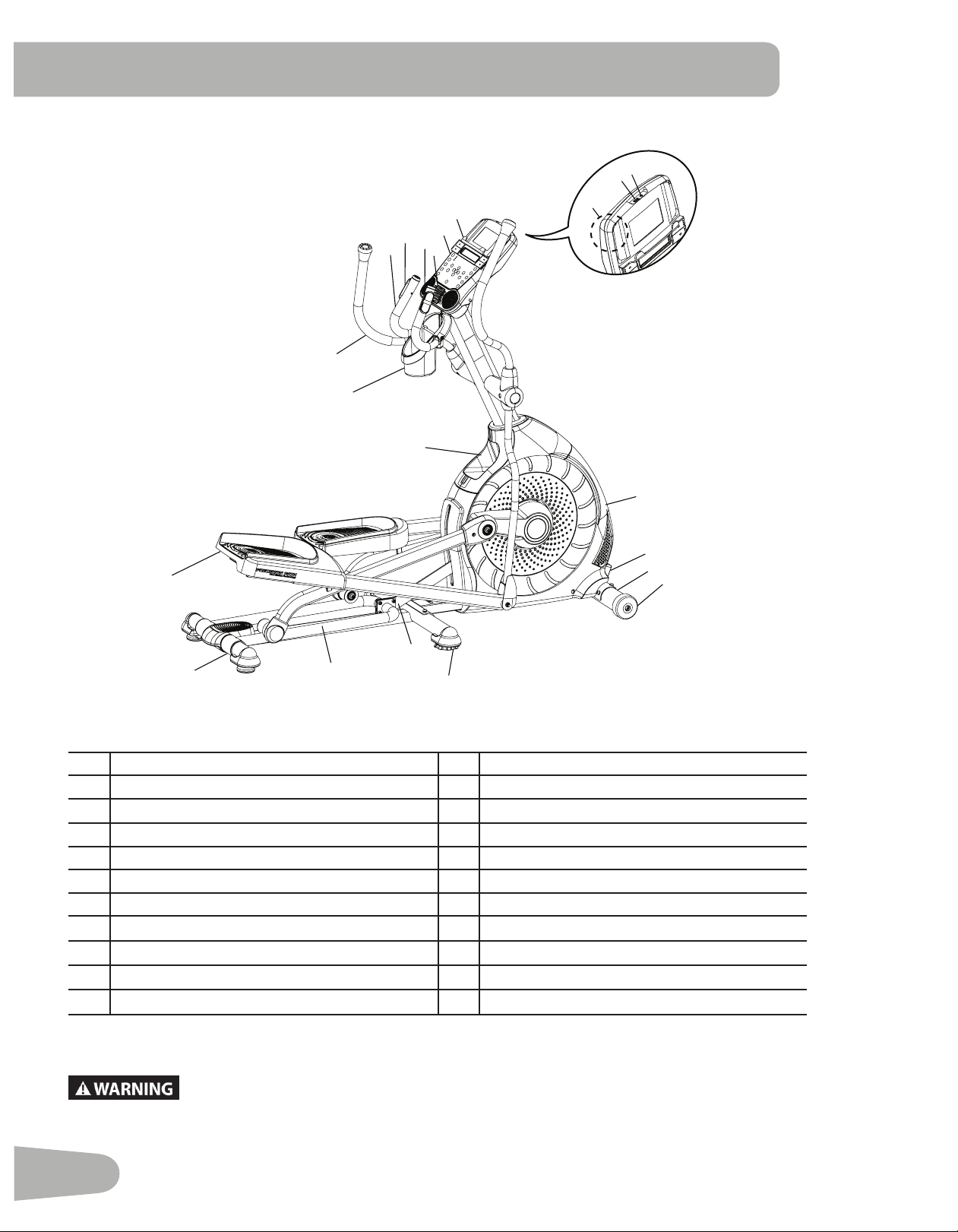
FEATURES
A Static Handlebar L Transport Roller
B Contact Heart Rate (CHR) Sensors M Leveler
C Speakers N Incline Arm
D Fan O Rail
E Media Tray P Transport Handle
F Console Q Foot Pedal
G USB Port R Storage Bin
H MP3 Input S Water Bottle Holder
I Fully Shrouded Flywheel T Upper Handlebar
J AC Adapter Inlet / Power Switch U Telemetry Heart Rate (HR) Receiver
K Stabilizer V Bluetooth
®
Connectivity (not shown)
Use the values calculated or measured by the machine’s computer for reference purposes only.
The heart rate displayed is an approximation and should be used for reference only. Over
exercising may result in serious injury or death. If you feel faint stop exercising immediately.
G
H
R
S
A
B
Q
P
O
M
N
I
J
K
L
C
F
E
D
T
U
25
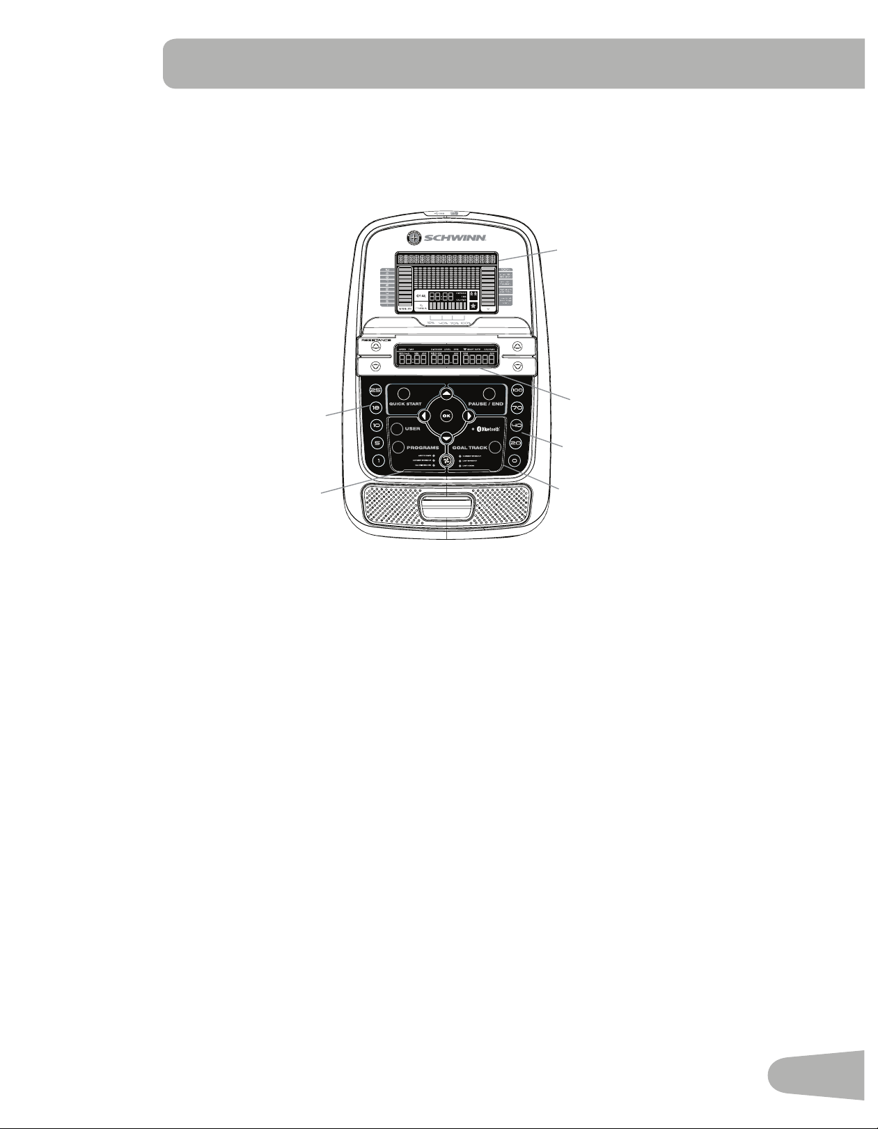
Console Features
The Console provides important information about your workout and lets you control the resistance levels while you
exercise.TheConsolefeaturestheSchwinnDualTrack
™
display with touch control buttons to navigate you through the
exerciseprograms.
Keypad Functions
Resistance Increase () button- Increases the workout resistance level
Resistance Decrease () button- Decreases the workout resistance level
Incline Increase () button- Increases the Incline angle of the Rail Assembly
Incline Decrease () button- Decreases the Incline angle of the Rail Assembly
QUICK START button- Begins a Quick Start workout
USERbutton-SelectsaUserprole
PROGRAMS button- Selects a category and workout program
PAUSE / END button- Pauses an active workout, ends a paused workout, or goes back to the previous screen
GOALTRACKbutton-DisplaystheWorkoutTotalsandAchievementsfortheselectedUserProle
Increase () button- Increases a value (age, time, distance, or calories) or moves through options
Left () button- Displays different workout values during a workout, and moves through options
OKbutton-StartsaProgramworkout,conrmsinformation,orresumesapausedworkout
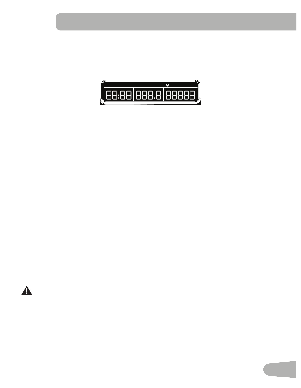
Upper Display
10%
40%
70%
1
2
3
4
5
6
7
8
9
10
Hr
INCLINE
Hr
Lower Display
Incline Level Quick Buttons
Resistance Level Quick Buttons
Achievement Indicator Lights
Fan
26
Right () button- Displays different workout values during a workout, and moves through options
Decrease () button- Decreases a value (age, time, distance, or calories) or moves through options
FAN button- Controls 3-speed fan
Resistance Level Quick Buttons- Shifts the resistance levels to the setting quickly during a workout
Incline Level Quick Buttons- Shifts the incline level to the setting quickly during a workout
Achievement Indicator Lights- when an achievement level is reached or a result is reviewed, the achievement indicator
light will activate
Schwinn Dual Track
™
Display
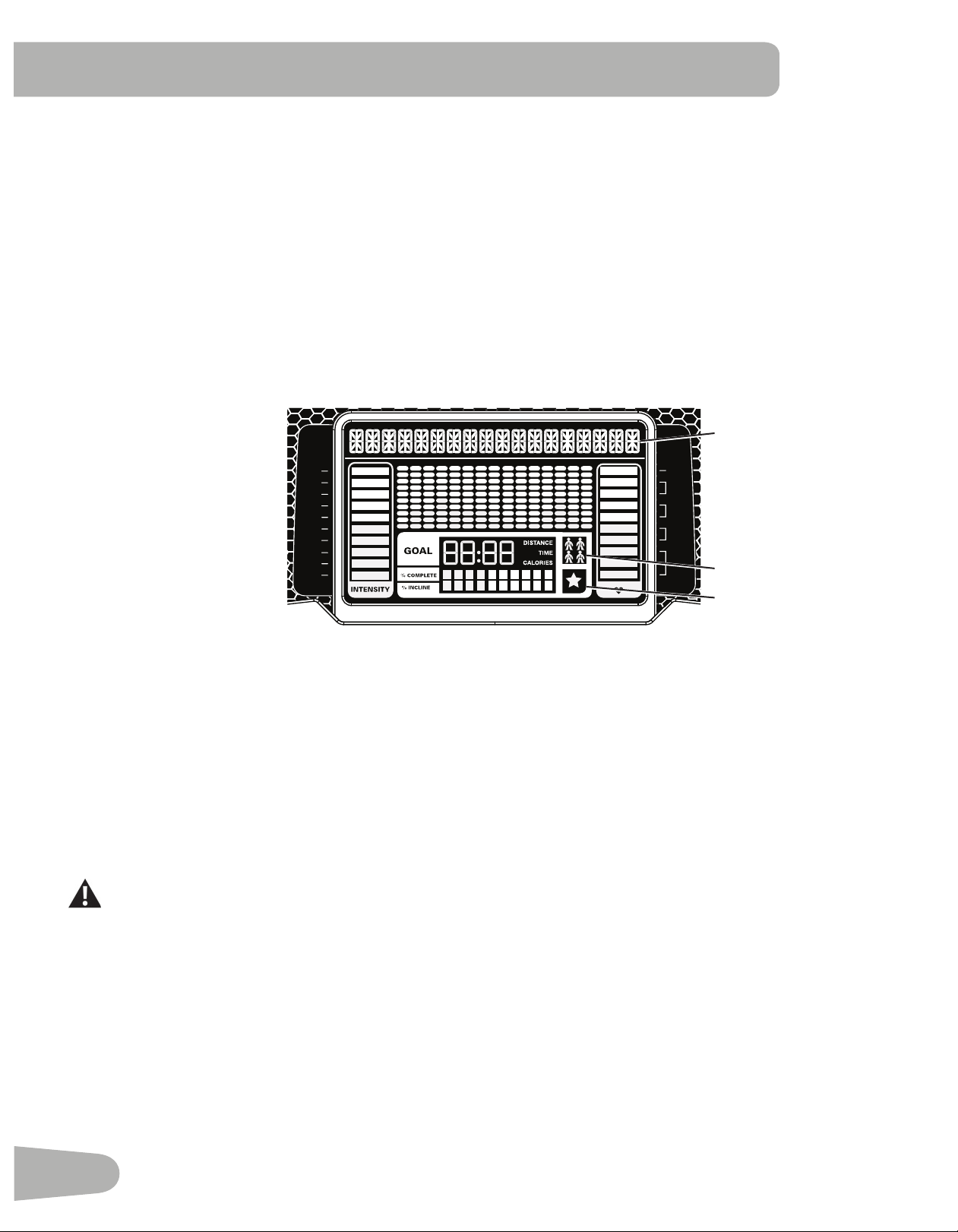
Upper Display Data
Program Display
TheProgramDisplayshowsinformationtotheUserandthegriddisplayareashowsthecourseprolefortheprogram.
Eachcolumnintheproleshowsoneinterval(workoutsegment).Thehigherthecolumn,thehighertheresistancelevel.
Theashingcolumnshowsyourcurrentinterval.
Intensity Display
The Intensity Display shows the level of work at that moment based on the current resistance level.
Heart Rate Zone Display
The Heart Rate Zone shows which zone the current heart rate value falls into for the current User. These Heart Rate
Zones can be used as a workout guide for a certain target zone (anaerobic, aerobic, or fat burn).
Consult a physician before you start an exercise program. Stop exercising if you feel pain or tightness in
your chest, become short of breath, or feel faint. Contact your doctor before you use the machine again.
The heart rate displayed is an approximation and should be used for reference only.
Note: If no heart rate is detected, the display will be blank.
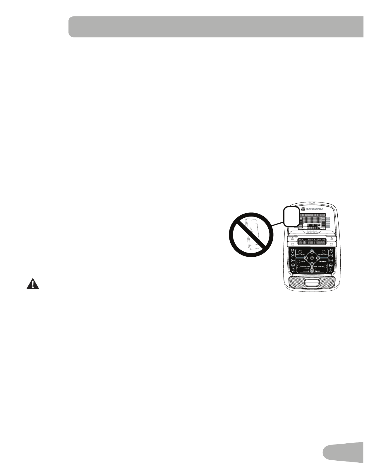
NOTICE: To prevent interference with the telemetry HR receiver, do not place any personal electronic devices in the left
side of the media tray.
Goal Display
The Goal Display shows the currently selected type of goal (Distance, Time or Calories), the current value to achieve the
goal, and the percent completed toward the goal.
User Display
TheUserDisplayshowswhichUserProleiscurrentlyselected.
TIMESPEED DISTANCE LEVEL CALORIESRPM HEART RATE
MPH km/h Hr MIN AVG MILES KM AVG BPM AVG
DISTANCE
QUICK START PAUSE/END
PROGRAMS
GOAL TRACK
USER
OK
100%
Anaerobic
80-90%
Aerobic
70-80%
Fat burn
50-70%
Warm up
Less than
50%
1
2
3
4
5
6
7
8
9
10
LONGEST WORKOUT LAST 7 DAYS
LAST 30 DAYSCALORIE RECORD
LAST WORKOUTCURRENT WORKOUT
SHARE AND TRACK
YOUR PROGRESS
1
25
18
10
100%
70%
20%
0%
5
40%
User Display
Achievement Display
Program Display
27
Achievement Display
The Achievement Display activates when a workout goal is reached or a workout milestone is surpassed from past
workouts. The Console display will congratulate and inform the User of their achievement, along with a celebratory sound.
Lower Display Data
TheLowerDisplayshowstheWorkoutValuesandcanbecustomizedforeachUser(Consultthe“EditUserProle”
section of this manual).
Speed
TheSpeeddisplayeldshowsthemachinespeedinmilesperhour(mph)orkilometersperhour(km/h).
Time
TheTIMEdisplayeldshowsthetotaltimecountoftheworkout,theaverageTimefortheUserProle,orthetotalopera-
tional time of the machine.
Note: If a Quick Start workout is performed for more than 99 minutes and 59 seconds (99:59), the units for Time will shift
to hours and minutes ( 1 hour, 40 minutes ).
Distance
The Distance display shows the distance count (miles or km) in the workout.
Note: To change the measurement units to English Imperial or metric, refer to the “Console Setup Mode” section in this
manual.
Level
The LEVEL display shows the current resistance level in the workout.
RPM
TheRPMdisplayeldshowsthepedalrevolutionsperminute(RPM).
Heart Rate (Pulse)
The Heart Rate display shows the beats per minute (BPM) from the heart rate monitor. When a heart rate signal is re-
ceivedbytheConsole,theiconwillash.
Consult a physician before you start an exercise program. Stop exercising if you feel pain or tightness in
your chest, become short of breath, or feel faint. Contact your doctor before you use the machine again.
The heart rate displayed is an approximation and should be used for reference only.
Calories
TheCaloriesdisplayeldshowstheestimatedcaloriesthatyouhaveburnedduringtheexercise.
TIMESPEED DISTANCE LEVEL CALORIESRPM HEART RATE
MPH km/h Hr MIN AVG MILES KM AVG BPM AVG
DISTANCE
QUICK START PAUSE/END
PROGRAMS
GOAL TRACK
USER
OK
100%
Anaerobic
80-90%
Aerobic
70-80%
Fat burn
50-70%
Warm up
Less than
50%
1
2
3
4
5
6
7
8
9
10
LONGEST WORKOUT LAST 7 DAYS
LAST 30 DAYSCALORIE RECORD
LAST WORKOUTCURRENT WORKOUT
SHARE AND TRACK
YOUR PROGRESS
1
25
18
10
100%
70%
20%
0%
5
40%

28
Bluetooth
®
Connectivity with the “Schwinn Trainer™” Fitness App
ThistnessmachineisequippedwithBluetooth
®
connectivity and can wirelessly sync with the Schwinn Trainer
™
Fitness
Apponsupporteddevices.TheSoftwareAppsyncswithyourtnessmachinetotracktotalcaloriesburned,time,
distance, and more. It records and stores every workout for quick reference. Plus, it automatically syncs your workout
data to Schwinn Connect™, MyFitnessPal
®
and Under Armour
®
Connected Fitness to make hitting your daily goals easier
than ever! Track your results and share with friends and family.
1. Download the free software app, named Schwinn Trainer
™
Fitness App. The software app is available on iTunes
®
and
Google Play
™
.
Note: For a complete list of supported devices, visit www.schwinnconnect.com/support
2. FollowtheinstructionsontheSoftwareApptosyncyourdevicetoyourexercisemachine.
TouploadyourworkoutletotheSchwinnConnect™website,andthenMyFitnessPal
®
and Under Armour
®
Connected
Fitness:
1. Select the Options tab in the upper left corner of the Software App, and click on “Settings”.
2. Select the “Schwinn Connect” option. Sign in to your account or create a new account. To create a new account, click
on the “Create New Account” option and follow the instructions.
3. To sync your workouts, click on the “Schwinn Connect” option, and then the “OK” button.
Note: The Schwinn Trainer
™
Fitness App will automatically sync your workouts after the initial syncing.
4. To sync your workout data from your Schwinn Connect™ account with MyFitnessPal
®
or Under Armour
®
Connected
Fitness, click on the desired program and login with your information.
Note: The Schwinn Trainer
™
Fitness App will automatically sync your workouts after the initial syncing.
An information and common questions guide for the Software App can be found online at
www.schwinnconnect.com/support/.
Track Your Results at www.schwinnconnect.com with a USB Drive
ThisfitnessmachineisequippedwithaUSBPortandcanexportyourWorkoutResultstoaUSBDrivetobeuploadedto
the Schwinn Connect™ website, and then to MyFitnessPal
®
and Under Armour
®
Connected Fitness. With the Workouts
exportedfromthefitnessmachine,connecttheUSBFlashDrivetoacomputeranduploadthefiletoyourSchwinn
Connect™ account.
Note: USB Flash Drives must be formatted in FAT32 for proper functionality.
1. From the Power-Up screen, push the USER button to select the desired User Profile.
2. Insert the USB Flash Drive into the USB Port on the Console.
3. The Console will display “SAVING TO USB”, and then “DO NOT REMOVE”. The current User Profile will begin to flash,
showingtheWorkoutResultsarebeingexportedtotheUSBFlashDrive.DonotremovetheUSBFlashDriveuntilthe
User Profile does not flash and the Console displays “REMOVE USB”.
Note:IftheWorkoutResultsontheUSBFlashDrivearecurrent,theConsolewillnotexporttheleagain.Asmore
workoutsarecompleted,theConsolewilltakelongertoexportalloftheWorkoutResults.Forlongerexports,
theConsolewilldisplayanexportstatuscount(exportedworkouts/totalnumberofworkouts).
4. WhentheexportiscompletetheUserProfilewillstopflashing,theConsolewilldisplay“USBCOMPLETE”,followedby
the “REMOVE USB” prompt. It is now safe to remove the USB Flash Drive.
5. The Console will display the Power-Up Mode screen.
IfaWorkoutiscompletedwithaUSBFlashDrivealreadyinserted,theConsolewillnotexportthenewWorkoutResults
untiltheConsoleexitstheResultsmodeanddisplaysthePower-UpModescreen.
TouploadyourworkoutlefromtheUSBFlashDrivetotheSchwinnConnect™website,andthenMyFitnessPal
®
and
Under Armour
®
Connected Fitness:
29
1. Insert the USB Drive with your workout data into a device connected to the internet.
2. Sign in to the Schwinn Connect™ website at www.schwinnconnect.com, or create a new account. To create a new
account, click on the “Create New Account” button.
3. Click on the Options tab in the upper left corner of the web page and select “Upload workout”.
4. Click on “Select Data File” and locate your USB Flash Drive.
5. Selecttheworkoutdatale,andclicktheOpenbutton.
6. Now click on the “Upload Data File” button. Your workout data will upload into your account
7. Toreviewyourworkout,clicktheOptionstabandselect“Home”.
8. To sync your workout data with MyFitnessPal
®
or Under Armour
®
Connected Fitness programs, select the Options tab
and select the “Connected Services“ option.
9. Click on the desired program option and login with your information.
Note: The Schwinn Connect™ website will automatically sync your workouts after the initial syncing.
An information and common questions guide for the Software App can be found online at
www.schwinnconnect.com/support/.
Remote Heart Rate Monitor
Monitoring your Heart Rate is one of the best procedures to control the
intensityofyourexercise.ContactHeartRate(CHR)sensorsareinstalled
to send your heart rate signals to the Console. The Console can also
read telemetry HR signals from a Heart Rate Chest Strap Transmitter that
operates in the 4.5kHz - 5.5kHz range.
Note: The heart rate chest strap must be an uncoded heart rate strap
from Polar Electro or an uncoded POLAR
®
compatible model.
(Coded POLAR
®
heart rate straps such as POLAR
®
OwnCode
®
chest straps will not work with this equipment.)
If you have a pacemaker or other implanted electronic device,
consult your doctor before using a wireless chest strap or other
telemetric heart rate monitor.
NOTICE: To prevent interference with the telemetry HR receiver, do not place any personal electronic devices in the left
side of the media tray.*
Contact Heart Rate Sensors
Contact Heart Rate (CHR) sensors send your heart rate signals to the Console. The CHR sensors are the stainless steel
parts of the Handlebars. To use, put your hands comfortably around the sensors. Be sure that your hands touch both the
topandthebottomofthesensors.Holdrm,butnottootightorloose.Bothhandsmustmakecontactwiththesensorsfor
the Console to detect a pulse. After the Console detects four stable pulse signals, your initial pulse rate will be shown.
Once the Console has your initial heart rate, do not move or shift your hands for 10 to 15 seconds. The Console will now
validatetheheartrate.Manyfactorsinuencetheabilityofthesensorstodetectyourheartratesignal:
• Movement of the upper body muscles (including arms) produces an electrical signal (muscle artifact) that can interfere
with pulse detection. Slight hand movement while in contact with the sensors can also produce interference.
• Calluses and hand lotion may act as an insulating layer to reduce the signal strength.
• Some Electrocardiogram (EKG) signals generated by individuals are not strong enough to be detected by the sensors.
• Theproximityofotherelectronicmachinescangenerateinterference.
INCLINE
Hr
30
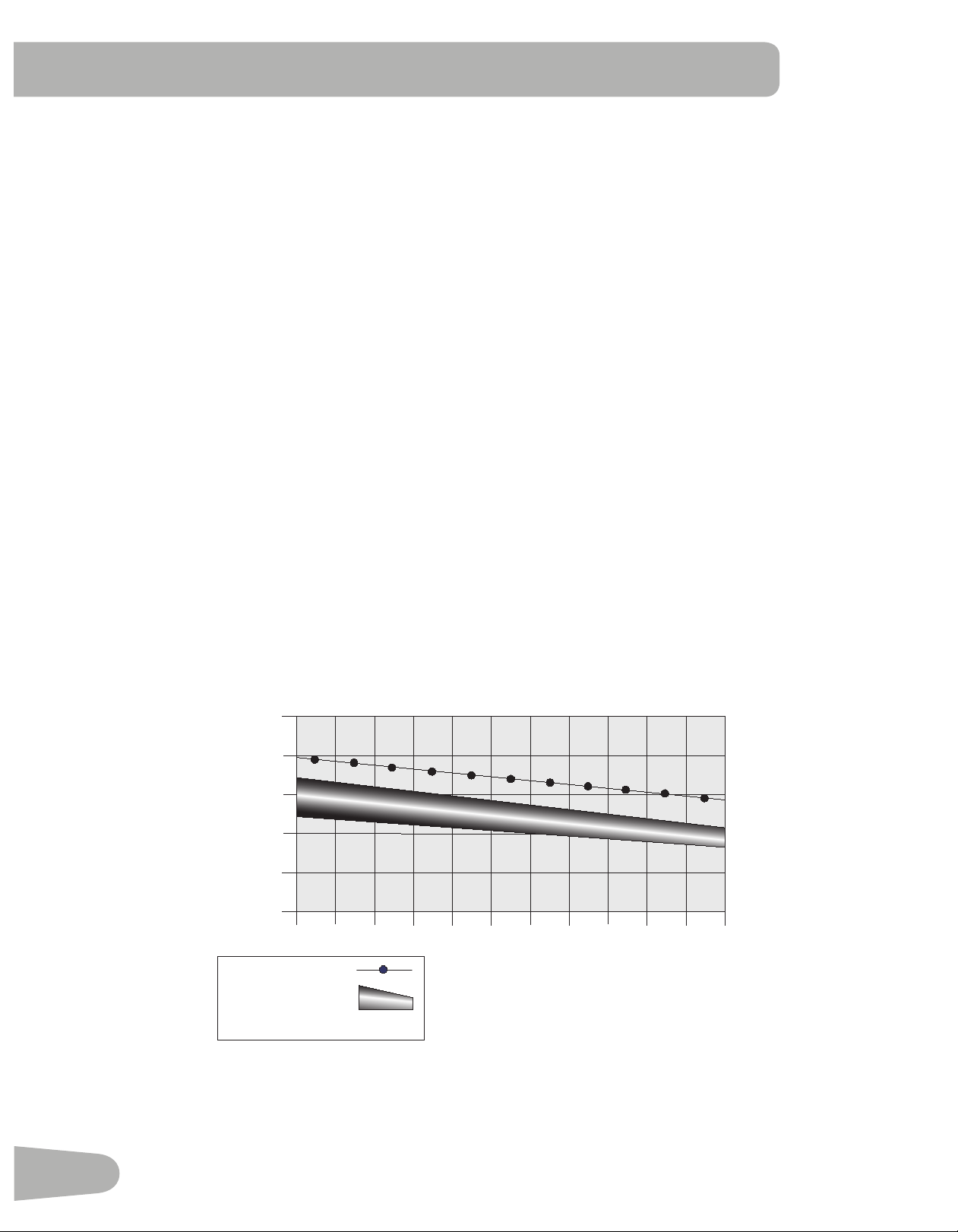
20-24
FAT-BURNING TARGET HEART RATE
Heart Rate BPM
(beats per minute)
Age
25-29
0
50
100
150
200
250
30-34 35-39 40-44 45-49 50-54 55-59 60-64 65-69 70+
196
191
186
181
176
171
166
161
156
151
146
167
162
158
154
150
145
141
137
133
128
126
Maximum Heart Rate
Target Heart Rate Zone
(keep within this range
for optimum fat-burning)
118
115
112
109
106
103
100
97
94
91
88
If your heart rate signal ever seems erratic after validation, wipe off your hands and the sensors and try again.
Heart Rate Calculations
Yourmaximumheartrateusuallydecreasesfrom220BeatsPerMinute(BPM)inchildhoodtoapproximately160BPMby
age60.Thisfallinheartrateisusuallylinear,decreasingbyapproximatelyoneBPMforeachyear.Thereisnoindication
thattraininginuencesthedecreaseinmaximumheartrate.Individualsofthesameagecouldhavedifferentmaximum
heartrates.Itismoreaccuratetondthisvaluebycompletingastresstestthanbyusinganagerelatedformula.
Yourat-restheartrateisinuencedbyendurancetraining.Thetypicaladulthasanatrestheartrateofapproximately72
BPM, whereas highly trained runners may have readings of 40 BPM or lower.
The Heart Rate table is an estimate of what Heart Rate Zone (HRZ) is effective to burn fat and improve your cardiovas-
cular system. Physical conditions vary, therefore your individual HRZ could be several beats higher or lower than what is
shown.
Themostefcientproceduretoburnfatduringexerciseistostartataslowpaceandgraduallyincreaseyourintensity
untilyourheartratereachesbetween60–85%ofyourmaximumheartrate.Continueatthatpace,keepingyourheart
rate in that target zone for over 20 minutes. The longer you maintain your target heart rate, the more fat your body will
burn.
The graph is a brief guideline, describing the generally suggested target heart rates based on age. As noted above, your
optimal target rate may be higher or lower. Consult your physician for your individual target heart rate zone.
Note:Aswithallexercisesandtnessregimens,alwaysuseyourbestjudgmentwhenyouincreaseyourexercisetime
or intensity.

31
OPERATIONS
What to Wear
Wearrubber-soledathleticshoes.Youwillneedtheappropriateclothesforexercisethatallowyoutomovefreely.
How Often Should You Exercise
Consult a physician before you start an exercise program. Stop exercising if you feel pain or tightness in
your chest, become short of breath, or feel faint. Contact your doctor before you use the machine again.
Use the values calculated or measured by the machine’s computer for reference purposes only. The heart
rate displayed on the console is an approximation and should be used for reference only.
• 3 times a week for 30 minutes each day.
• Schedule workouts in advance and try to follow the schedule.
Mounting and Dismounting the Machine
Care should be used when mounting or dismounting the machine.
Be aware that the Pedals and the Handlebars are connected and when either of these parts move the other
does as well. In order to avoid possible serious injury, only grasp the Static Handlebars to steady yourself.
Tomountthetnessmachine:
1. Move the Pedals until the one nearest you is in the lowest position.
2. Grasp the Static Handlebars under the Console.
3. Steadying yourself with the Static Handlebars, step up onto the lowest Pedal and place your other foot onto the
opposite Pedal.
Todismountthetnessmachine:
1. Move the Pedal you want to dismount from to the highest position, and bring the machine to a complete stop.
This machine is not equipped with a free-wheel. Pedal speed should be reduced in a controlled manner.
2. Grasp the Static Handlebars under the Console to steady yourself.
3. Withyourweightonthelowestfoot,swingtheupperfootoffthemachineanddownontotheoor.
4. Step off of the machine and release your grip from the Static Handlebars.
Power-Up / Idle Mode
The Console will enter Power-Up / Idle Mode if it is plugged into a power source and the Power Switch turned on, any but-
ton is pushed, or if it receives a signal from the RPM sensor as a result of pedaling the machine.
Auto Shut-Off (Sleep Mode)
IftheConsoledoesnotreceiveanyinputinapproximately5minutes,itwillautomaticallyshutoff.TheLCDdisplayisoff
while in Sleep Mode.
Note: The Console does not have an On/Off switch.
To disconnect, turn all controls to the off position, then remove plug from outlet.

32
Initial Setup
Duringtherstpower-up,theConsoleshouldbesetupwiththedate,timeandyourpreferredmeasurementunits.
1. Date:PushtheIncrease/Decreasebuttonstoadjustthecurrentlyactivevalue(ashing).PushtheLeft/Rightbuttons
to change which segment is the currently active value (month / day / year).
2. Push OK to set.
3. Time:PushtheIncrease/Decreasebuttonstoadjustthecurrentlyactivevalue(ashing).PushtheLeft/Rightbuttons
to change which segment is the currently active value (hour / minute / AM or PM).
4. Push OK to set.
5. Units of Measurement: Push the Increase/Decrease buttons to adjust between “MILES” (Imperial English) or “KM”
(metric).
6. Push OK to set. The Console goes back to the Power-Up / Idle Mode screen.
Note: To adjust these selections, consult the “Console Set-Up Mode” section.
Quick Start ( Manual ) Program
The Quick Start ( Manual ) program lets you start a workout without entering any information.
During a Manual Workout, each column represents a 2 minute time period. The active column will advance across the
screenevery2minutes.Iftheworkoutlastsformorethan30minutes,theactivecolumnisxedonthefarthestcolumnon
the right and pushes the previous columns off the display.
1. Stand on the machine.
2. PushtheUserbuttontoselectthecorrectUserprole.IfyoudonothaveaUserprolesetup,youcanselectaUser
prolethathasnocustomizeddata(defaultvaluesonly).
3. Push the QUICK START button to start the Manual program.
4. To change the resistance level, push the Resistance Increase/Decrease buttons. The current interval and future
intervals are set to the new level. The default Manual resistance level is 4. The time will count up from 00:00.
Note: If a Manual workout is performed for more than 99 minutes and 59 seconds (99:59), the units for Time will shift to
hours and minutes ( 1 hour, 40 minutes ).
5. When done with your workout, stop pedaling and push PAUSE/END to pause the workout. Push PAUSE/END again
to end the workout.
Note: The workout results are recorded to the current User Profile.
User Profiles
The Console lets you store and use 4 User profiles. The User profiles automatically record the workout results for each
workout, and allow the workout data to be reviewed.
The User profile stores the following data:
• Name—up to 10 characters
• Age
• Weight
• Height
• Gender
• Preferred Workout Values

33
Select a User Profile
EveryworkoutissavedtoaUserProle.BesuretoselecttheproperUserProlebeforestartingaworkout.ThelastUser
that completed a workout will be the default user.
UserProlesareassignedthedefaultvaluesuntiltheyarecustomizedbyediting.BesuretoedittheUserProleformore
accurate calorie and heart rate information.
FromthePower-UpModescreen,pushtheUserbuttontoselectoneoftheUserProles.TheConsolewilldisplaythe
nameoftheUserProleandtheUserProleIcon.
Edit User Profile
1. From the Power-Up Mode screen, push the User button toselectoneoftheUserProles.
2. Push the OK button to select it.
3. The Console display shows the EDIT prompt and the current User Profile name. Push OK to start the Edit User Prole
option.
ToexittheEditUserProleoption,pushthePAUSE/ENDbuttonandtheconsolewillgobacktothePower-Up Mode
screen.
4. The Console display shows the NAME prompt and the current User Profile name.
Note: The User name will be blank if this is the first edit. The name of a User Profile is limited to 10 characters.
The currently active segment will flash. Use the Increase/Decrease buttons to move through the alphabet and blank
space (found between A and Z). To set each segment, use the Left() or Right() buttons to shift between segments.
Push the OK button to accept the displayed User name.
5. To edit the other User data (EDIT AGE, EDIT WEIGHT, EDIT HEIGHT, EDIT GENDER), use the Increase/Decrease
buttons to adjust, and push OK to set each entry.
6. The Console display shows the SCAN prompt. This option controls how the workout values are displayed in the Lower
Display during a workout. The “OFF” setting allows the user to push the RIGHT or LEFT buttons to view the other
workout value channels when desired. The “ON” setting allows the Console to automatically display the workout value
channels every 6 seconds.
The default is “OFF”.
Push the OK button to set how the workout values are displayed.
7. TheConsoledisplayshowstheWIRELESSHRprompt.IfyouareusingtheConsolespeakersattheirhighersettings
and / or using a larger sized personal electronic device, the Console may show Heart Rate interference. This option
allows the Telemetry Heart Rate Receiver to be deactivated blocking the interference.
The Upper Display shows the current value setting: “ON” or “OFF”. Push the Increase() or Decrease() buttons to
change the value.
The default is “ON”.
Push the OK button to set the Telemetry Heart Rate Receiver to active.
8. The Console display shows the EDIT LOWER DISPLAY prompt. This option allows you to customize which Workout
Values are displayed during a workout.
TheLowerDisplaywillshowalloftheworkoutvalues,withtheactiveWorkoutValueashing.TheUpperDisplay
shows the active value setting: “ON” or “OFF”. Push the Increase() or Decrease() buttons to hide the active
workout value, and push the Left() or Right() buttons to shift the active workout value.
Note: to show a hidden workout value, repeat procedure and change Upper Display value to “ON” for that value.
When done with customizing the Lower Display, push the OK button to set it.
Hr
34
9. The Console will go to the Power-Up Mode screen with the user selected.
Reset a User Profile
1. From the Power-Up Mode screen, push the User button toselectoneoftheUserProles.
2. Push the OK button to select it.
3. The Console display shows the current User Profile name and the EDIT prompt. Push the Increase() or Decrease()
buttons to change the prompt.
Note: ToexittheEditUserProleoption,pushthePAUSE/ENDbuttonandtheconsolewillgobacktothePower-Up
Mode screen.
4. The Console display shows the RESET prompt and the current User Profile name. Push OK to start the Reset User
Proleoption.
5. The Console will now confirm the request to reset the User profile (the default selection is ‘NO’). Push the Increase()
or Decrease() buttons to adjust the selection.
6. Push OK to make your selection.
7. TheConsolewillgotothePower-UpModescreen.
Changing Resistance Levels
Push the Resistance Level Increase() or Decrease() buttons to change the resistance level at any time in a workout
program. To rapidly change the resistance level, push the desired Resistance Level Quick Button. The Console will adjust
to the selected resistance level of the quick button.
Changing Incline Levels
Push the Incline Level Increase() or Decrease() buttons to change the incline
angle of the rail assembly at any time in a workout program. To rapidly change the in-
cline level, push the desired Incline Level Quick Button. The Console will adjust to the
selected incline level of the quick button.
Be sure the area below the machine is clear before lowering. Fully lower
the Incline Assembly after each workout.
Exercise on this machine requires coordination and balance. Be sure to
anticipate that changes in speed, incline angle and resistance level can
occur during workouts, and be attentive in order to avoid loss of balance
and possible injury.
Note: Be sure that the workout space you are utilizing has adequate height clearance, taking into consideration the
heightoftheuserandthemaximuminclineoftheellipticalmachine.Thoughtheinclineanglechangestheexercise
motion, it does not affect the calorie values.
Profile Programs
Theseprogramsautomatedifferentresistanceandworkoutlevels.TheProleProgramsareorganizedintoCategories
(Fun Rides, Mountains, and Challenges).
Note:OnceaUserviewsalltheCategories,theywillbeexpandedtodisplaytheProgramswithineachofthe
Categories.
35
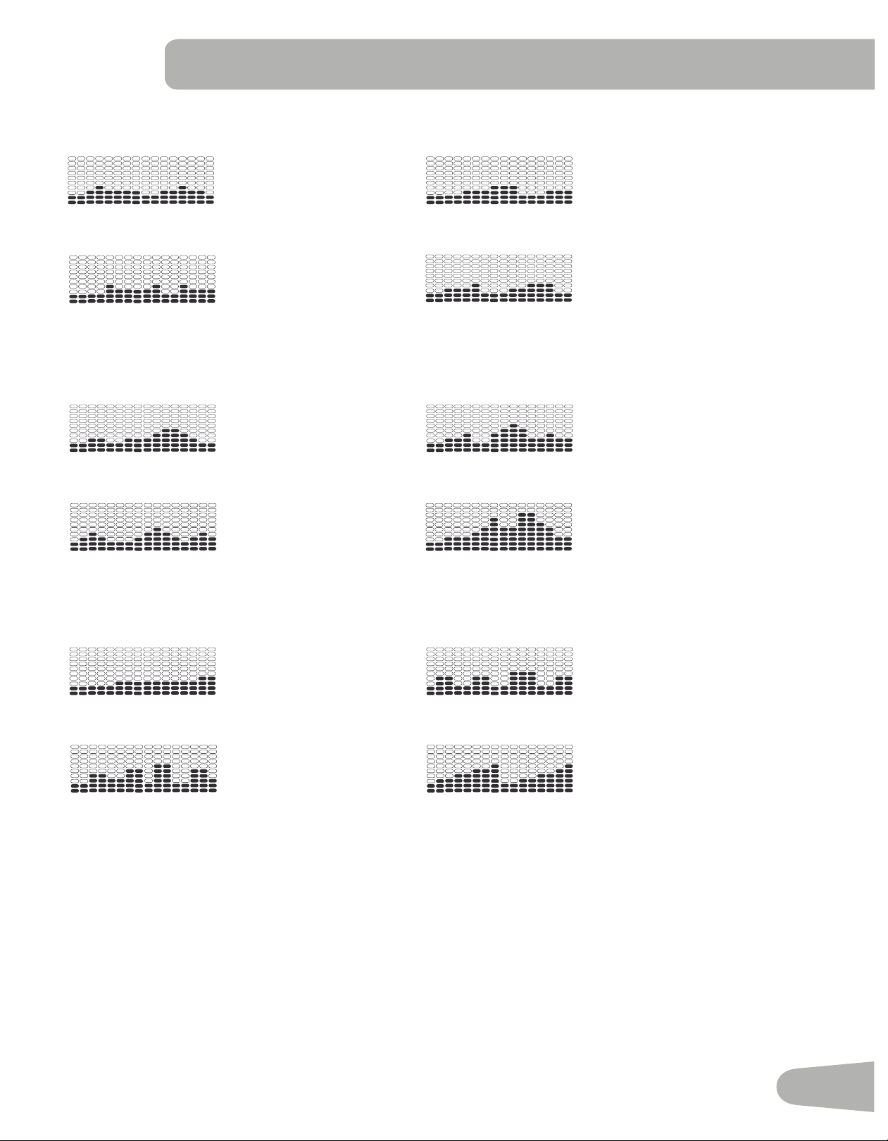
FUN RIDES
Rolling Hills Ride in the Park
Secondary Case 6: Profile Programs
Rolling Hills
FUN RIDES
Ride in the Park Easy Tour
Pike’s Peak
MOUNTAINS
Mount Hood Pyramids
Uphill Finish
CHALLENGES
Cross-Training Interval
Stream Crossing
Summit Pass
Stairs
REVED : 122612
Secondary Case 6: Profile Programs
Rolling Hills
FUN RIDES
Ride in the Park Easy Tour
Pike’s Peak
MOUNTAINS
Mount Hood Pyramids
Uphill Finish
CHALLENGES
Cross-Training Interval
Stream Crossing
Summit Pass
Stairs
REVED : 122612
Easy Tour Stream Crossing
Secondary Case 6: Profile Programs
Rolling Hills
FUN RIDES
Ride in the Park Easy Tour
Pike’s Peak
MOUNTAINS
Mount Hood Pyramids
Uphill Finish
CHALLENGES
Cross-Training Interval
Stream Crossing
Summit Pass
Stairs
REVED : 122612
Secondary Case 6: Profile Programs
Rolling Hills
FUN RIDES
Ride in the Park Easy Tour
Pike’s Peak
MOUNTAINS
Mount Hood Pyramids
Uphill Finish
CHALLENGES
Cross-Training Interval
Stream Crossing
Summit Pass
Stairs
REVED : 122612
MOUNTAINS
Pike’s Peak Mount Hood
Secondary Case 6: Profile Programs
Rolling Hills
FUN RIDES
Ride in the Park Easy Tour
Pike’s Peak
MOUNTAINS
Mount Hood Pyramids
Uphill Finish
CHALLENGES
Cross-Training Interval
Stream Crossing
Summit Pass
Stairs
REVED : 122612
Secondary Case 6: Profile Programs
Rolling Hills
FUN RIDES
Ride in the Park Easy Tour
Pike’s Peak
MOUNTAINS
Mount Hood Pyramids
Uphill Finish
CHALLENGES
Cross-Training Interval
Stream Crossing
Summit Pass
Stairs
REVED : 122612
Pyramids Summit Pass
Secondary Case 6: Profile Programs
Rolling Hills
FUN RIDES
Ride in the Park Easy Tour
Pike’s Peak
MOUNTAINS
Mount Hood Pyramids
Uphill Finish
CHALLENGES
Cross-Training Interval
Stream Crossing
Summit Pass
Stairs
REVED : 122612
Secondary Case 6: Profile Programs
Rolling Hills
FUN RIDES
Ride in the Park Easy Tour
Pike’s Peak
MOUNTAINS
Mount Hood Pyramids
Uphill Finish
CHALLENGES
Cross-Training Interval
Stream Crossing
Summit Pass
Stairs
REVED : 122612
CHALLENGES
Uphill Finish Cross-Training
Secondary Case 6: Profile Programs
Rolling Hills
FUN RIDES
Ride in the Park Easy Tour
Pike’s Peak
MOUNTAINS
Mount Hood Pyramids
Uphill Finish
CHALLENGES
Cross-Training Interval
Stream Crossing
Summit Pass
Stairs
REVED : 122612
Secondary Case 6: Profile Programs
Rolling Hills
FUN RIDES
Ride in the Park Easy Tour
Pike’s Peak
MOUNTAINS
Mount Hood Pyramids
Uphill Finish
CHALLENGES
Cross-Training Interval
Stream Crossing
Summit Pass
Stairs
REVED : 122612
Interval Stairs
Secondary Case 6: Profile Programs
Rolling Hills
FUN RIDES
Ride in the Park Easy Tour
Pike’s Peak
MOUNTAINS
Mount Hood Pyramids
Uphill Finish
CHALLENGES
Cross-Training Interval
Stream Crossing
Summit Pass
Stairs
REVED : 122612
Secondary Case 6: Profile Programs
Rolling Hills
FUN RIDES
Ride in the Park Easy Tour
Pike’s Peak
MOUNTAINS
Mount Hood Pyramids
Uphill Finish
CHALLENGES
Cross-Training Interval
Stream Crossing
Summit Pass
Stairs
REVED : 122612
Workout Profile and Goal Program
TheConsoleletsyouselecttheProleProgramandtypeofGoalforyourworkout(Distance,TimeorCalories),andset
the Goal value.
1. Stand on the machine.
2. PushtheUserbuttontoselectthecorrectUserprole.
3. Push the Programs button.
4. Push the Left() or Right() buttons to select a Category of Workout.
5. Push the Increase() or Decrease() buttons to select a Profile Workout, and push OK.
6. Use the Increase() or Decrease() buttons to select a type of Goal (Distance, Time or Calories), and push OK.

36
7. Use the Increase() or Decrease() buttons to adjust the workout value.
8. Push OK to begin the goal-oriented workout. The GOAL value will count down as the value for percent completed
increases.
Note: During a Calories Goal, each column is for a 2 minute time period. The active column will advance across the
screenevery2minutes.Iftheworkoutlastsformorethan30minutes,theactivecolumnwillxtothelastright
column and push the previous columns off the display.
Fitness Test Program
TheFitnessTestmeasurestheimprovementstoyourphysicaltnesslevel.Thetestcomparesyourpoweroutput(in
watts)toyourheartrate.Asyourtnesslevelimproves,yourpoweroutputwillincreaseatagivenheartrate.
Note: The Console must be able to read the heart rate information from the Contact Heart Rate (CHR) sensors or Heart
Rate Monitor (HRM) to work correctly.
YoucanstarttheFitnessTestfromtheFEEDBACKcategory.TheFitnessTestprogramrstpromptsyoutoselectyour
tnesslevel—Beginner(“BEG”)orAdvanced(“ADV”).TheConsolewillusetheAgeandWeightvaluesfortheselected
UserProletocalculatetheFitnessScore.
Start to work out and hold the Heart Rate Sensors. When the test starts, the intensity of the workout slowly increases. This
means you will work harder, and as a result, your heart rate increases. The intensity continues to increase automatically
untilyourheartratereachesthe“TestZone”.Thiszoneisindividuallycomputedtobenear75percentofthemaximum
heartrateofyourUserProle.WhenyoureachtheTestZone,themachineholdstheintensitysteadyfor3minutes.
This lets you reach a stable condition (where your heart rate becomes steady). At the end of the 3 minutes, the Console
measures your heart rate and the power output. These numbers, along with information about your age and weight, are
computed to produce a “Fitness Score”.
Note: Fitness Test scores should only be compared to your previous scores and not to other User Profiles.
Compare your Fitness Scores to see your improvement.
Recovery Test Program
RecoveryTestshowshowquicklyyourheartrecoversfromanexercisestatetoamorerestfulstate.Improvedrecoveryis
anindicatorofincreasingtness.
Note: The Console must be able to read the heart rate information from the Contact Heart Rate (CHR) sensors or Heart
Rate Monitor (HRM) to work correctly.
From an elevated heart rate, select the Recovery Test Program. The Console will show “STOP EXERCISING” and the
goalwillbegintocountdown.Stopexercisingbutcontinuetogripthecontactheartratesensors.After5seconds,the
display will show “RELAX” and will continue to count down to 00:00. For the entire minute the console will also show your
heart rate. You must grip the heart rate sensors for the duration of the test if not using a Remote Heart Rate Monitor.
The display will continue to show “RELAX” and your heart rate until the goal reaches 00:00. The console will then calcu-
late your recovery score.
Recovery Score = Your heart rate at 1:00 (the beginning of the test) minus your heart rate at 00:00 (the end of the test).
The higher the Recovery Test score value, the quicker your heart rate is returning to a more restful state and is an indica-
tionofimprovingtness.Byrecordingthesevaluesovertimeyoucanseethetrendtowardbetterhealth.
When you select the Recovery Test Program and there is no heart rate signal or display, the Console will show “NEED
HEART RATE”. This message will show for 5 seconds. If no signal is detected, the program will end.
Helpful Tip: For a more relevant score, try to obtain a steady heart rate for 3 minutes before starting the Recovery Pro-
gram. This will be easier to achieve, and obtain the best result, in the Manual program so you can control the levels of
resistance.

37
Heart Rate Control (HRC) Workout Programs
The Heart Rate Control (HRC) programs let you set a heart rate goal for your workout. The program monitors your heart
rate in beats per minute (BPM) from the Contact Heart Rate (CHR) sensors on the machine or from a Heart Rate Monitor
(HRM) chest strap, and adjusts the workout to keep your heart rate in the selected zone.
Note: The console must be able to read the heart rate information from the CHR sensors or HRM for the HRC program
to work correctly.
The Target Heart Rate programs use your age and other User information to set the Heart Rate Zone values for your
workout. The console display then gives prompts for you to set up your workout:
1. Select the Heart Rate Control workout level: BEGINNER ( “BEG” ) or ADVANCED ( “ADV” ) and push OK.
2. Push the Increase() or Decrease() buttons to selectthepercentageofmaximumheartrate:50–60%,60–70%,
70–80%,80–90%.
Consult a physician before you start an exercise program. Stop exercising if you feel pain or tightness in
your chest, become short of breath, or feel faint. Contact your doctor before you use the machine again.
Use the values calculated or measured by the machine’s computer for reference purposes only. The heart
rate displayed on the console is an approximation and should be used for reference only.
3. Push the Increase() or Decrease() buttons to select the Goal type, and push OK.
4. Push the Increase() or Decrease() buttons to set the goal value for the workout.
Note: Be sure to allow time for your heart rate to reach the desired heart rate zone when setting the goal.
5. Push OK to start the workout.
A User can set a Heart Rate zone instead of a value by selecting the Heart Rate Control - User program. The Console will
adjust the workout to keep the User in the desired Heart Rate zone.
1. Select HEART RATE CONTROL - USER, and push OK.
2. Push the Increase() or Decrease() buttons to set the Heart Rate zone for the workout, and push OK. The Console
shows the Heart Rate zone (percent) on the left, and the Heart Rate range for the User on the right side of the display.
Consult a physician before you start an exercise program. Stop exercising if you feel pain or tightness in
your chest, become short of breath, or feel faint. Contact your doctor before you use the machine again.
Use the values calculated or measured by the machine’s computer for reference purposes only. The heart
rate displayed on the console is an approximation and should be used for reference only.
3. Push the Increase() or Decrease() buttons to select the Goal type, and push OK.
4. Push the Increase() or Decrease() buttons to set the value for the workout.
5. Push OK to start the workout.
Changing a Workout Program During a Workout
The Console allows a different Workout Program to be started from an active workout.
1. From an active workout, push PROGRAMS.
2. Push the Increase() or Decrease() buttons to select the desired workout program, and push OK.
3. Push the Increase() or Decrease() buttons to select the Goal type, and push OK.
4. Push the Increase() or Decrease() buttons to set the value for the workout.
5. Push OK to stop the active workout and start the new workout.
ThepreviousworkoutvaluesaresavedtotheUserProle.

38
Pausing or Stopping
The Console will go into Pause Mode if the user stops pedaling and pushes PAUSE/END during a workout, or there is no
RPM signal for 5 seconds (user not pedaling). The Console will cycle through a series of messages that change every 4
seconds:
- WORKOUT PAUSED
- PEDAL TO CONTINUE (if a bike) / STRIDE TO CONTINUE (if an elliptical)
- PUSH END TO STOP
During a paused workout, you can use the Increase/Decrease buttons to move through the result channels manually.
1. Stop pedaling and push the PAUSE/END button to pause your workout.
2. To continue your workout, push OK or start pedaling.
To stop the workout, push the PAUSE/END button. The Console will go into Results / Cool Down mode.
Results / Cool Down Mode
After a workout the GOAL display shows 03:00 and then starts to count down. During this Cool Down period, the Console
showstheWorkoutResults.AllworkoutsexceptQuickStarthavea3-minuteCoolDownperiod.
The LCD display shows the Current Workout values in three channels:
a.) TIME (total), DISTANCE (total), and CALORIES (total)
b.) SPEED (average), RPM (average), and HEART RATE (average)
c.) TIME (average), LEVEL (average), and CALORIES (average).
Push the Left() or Right() buttons to move through the result channels manually.
During the Cool Down period, the Resistance Level will adjust to a third of the average Level of the workout. The Cool
Down resistance level can be adjusted with the Resistance Increase and Decrease buttons, but the Console will not dis-
play the value.
You can push PAUSE/END to stop the Results / Cool Down period and go back to Power-Up Mode. If there is no RPM or
HR signal, the Console automatically goes into Sleep Mode.
GOAL TRACK Statistics (and Achievements)
ThestatisticsfromeveryworkoutarerecordedtoaUserProle.
The Nautilus Dual Track
™
Console shows the Goal Track workout Statistics on the Lower Display in three channels:
a.) TIME (total), DISTANCE (total), and CALORIES (total)
b.) SPEED (average), RPM (average), and HEART RATE (average)
c.) TIME (average), DISTANCE (average) / or LEVEL (average) *, and CALORIES (average)
* If the Goal Track Statistic is a single workout, LEVEL (average) is displayed. If the Goal Track Statistic is a
combination of multiple workouts, DISTANCE (average) is displayed instead of LEVEL (average).
ToviewtheGOALTRACKstatisticsofaUserProle:
1. From the Power-Up screen, pushtheUserbuttontoselectthecorrectUserprole.
2. Push the GOAL TRACK button. The Console will display the LAST WORKOUT values and activate the corresponding
Achievement light.
Note: Goal Track statistics can be viewed even during a workout. Push GOAL TRACK and the LAST WORKOUT values
willbedisplayed.TheworkoutvaluesforthecurrentworkoutwillbehiddenexceptfortheGOALdisplay.Push
GOAL TRACK again to return to the Power-Up screen.
39
3. Push the Increase() buttontomovetothenextGOALTRACKstatistic,“LAST7DAYS”.TheConsolewilldisplay
the calories burned on the display (50 calories per segment) for the previous seven days, along with the workout value
totals. Use the Left() or Right() buttons to move through all the workout statistic channels.
4. Push the Increase() button to move to “LAST 30 DAYS”. The Console will display the total values for the previous
thirty days. Use the Left() or Right() buttons to move through all the workout statistic channels.
5. Push the Increase() button to move to the “LONGEST WORKOUT”. The Console will display the workout values with
the most Time value. Use the Left() or Right() buttons to move through all the workout statistic channels.
6. Push the Increase() button to move to the “CALORIE RECORD”. The Console will display the workout values with the
most Calories value. Use the Left() or Right() buttons to move through all the workout statistic channels.
7. Pushthe Increase() button to move to “BMI”, or BodyMassIndex. The Console will display the BMI value based on
the User settings. BesuretheheightvalueiscorrectforyourUserProle,andtheweightvalueiscurrent.
The BMI Measurement is a useful tool that shows the relationship between weight and height that is associated with body
fat and health risk. The table below gives a general rating for the BMI score:
Underweight Below 18.5
Normal 18.5 – 24.9
Overweight 25.0 – 29.9
Obesity 30.0 and above
Note: The rating may overestimate body fat in athletes and others who have a muscular build. It may also underesti-
mate body fat in older persons and others who have lost muscle mass.
Contact your doctor for more information about Body Mass Index (BMI) and the weight that is appropriate
for you. Use the values calculated or measured by the machine’s computer for reference purposes only.
8. Push the Increase() button to move to the “SAVE TO USB - OK?” prompt. Push OK and the “ARE YOU SURE?
-NO” prompt will display. Push the Increase() button to change it to yes and push OK. The Console will display the
“INSERT USB” prompt. Insert a USB Flash Drive into the USB Port. The Console will record the Statistics to the USB
Flash Drive.
The Console will display “SAVING”, and then “REMOVE USB” when it is safe to remove the USB Flash Drive.
Note:PushthePAUSE/ENDbuttontoforceanexitfromthe“SAVING”prompt.
9. Push the Increase() button to move to the “CLEAR WORKOUT DATA -OK?” prompt. Push OK, and the “ARE YOU
SURE? - NO” prompt will display. Push the Increase() button to change to the “ARE YOU SURE? - YES” display, and
push OK. The user workouts have been reset.
10. Push GOAL TRACK to return to the Power-Up screen.
When a User performs a workout that surpasses the “LONGEST WORKOUT” or “CALORIE RECORD” of the previous
workouts, the Console will congratulate with an audible sound and tell the User the new achievement. The corresponding
Achievement Indicator Light will also be active.

40
CONSOLE SETUP MODE
The Console Setup Mode lets you input the date and time, set the units of measurement to either English or Metric,
change the machine type, control the sound settings ( on/ off), or see maintenance statistics (Error Log and Run Hours –
for service technician use only).
1. Hold down the PAUSE/END button and Right button together for 3 seconds while in the Power-Up Mode to go into
the Console Setup Mode.
Note: PushPAUSE/ENDtoexittheConsoleSetupModeandreturntothePower-UpModescreen.
2. The Console display shows the Date prompt with the current setting. To change, push the Increase/Decrease buttons
toadjustthecurrentlyactivevalue(ashing).PushtheLeft/Rightbuttonstochangewhichsegmentisthecurrently
active value (month / day / year).
3. Push OK to set.
4. The Console display shows the Time prompt with the current setting. Push the Increase/Decrease buttons to adjust
thecurrentlyactivevalue(ashing).PushtheLeft/Rightbuttonstochangewhichsegmentisthecurrentlyactivevalue
(hour / minute / AM or PM).
5. Push OK to set.
6. The Console display shows the Units prompt with the current setting. To change, push OK to start the Units option.
Push the Increase/Decrease buttons to change between “MILES” (Imperial English units) and “KM” (metric units).
Note: If the units change when there is data in User Statistics, the statistics convert to the new units.
7. PushOKtoset.
8. The Console display shows the Machine Type prompt with the current setting. Push the Increase/Decrease buttons to
change between “BIKE” and Elliptical (“ELIP”).
9. Push OK to set.
10. The Console display shows the Sound Settings prompt with the current setting. Push the Increase/Decrease buttons
to change between “ON” and “OFF”.
11. Push OK to set.
12. The Console display shows the TOTAL RUN HOURS for the machine.
13. Forthenextprompt,pushtheOKbutton.
14. The Console display shows the Software Version prompt.
15. Forthenextprompt,pushtheOKbutton.
16 . The Console will display the Power-Up Mode screen.

41
MAINTENANCE
Read all maintenance instructions fully before you start any repair work. In some conditions, an assistant is required to do
the necessary tasks.
Equipment must be regularly examined for damage and repairs. The owner is responsible to make sure that
regular maintenance is done. Worn or damaged components must be repaired or replaced immediately.
Only manufacturer supplied components can be used to maintain and repair the equipment.
If at any time the Warning labels become loose, unreadable or dislodged, contact your local distributor for
replacement labels.
To reduce the risk of electrical shock or unsupervised usage of the equipment, always unplug the
power cord from the wall outlet and the machine and wait 5 minutes before cleaning, maintaining or repairing the
machine. Place the power cord in a secure location.
Daily:
Beforeeachuse,examinetheexercisemachineforloose,broken,damaged,orwornparts.
Donotuseiffoundinthiscondition.Repairorreplaceallpartsattherstsignofwearor
damage. After each workout, use a damp cloth to wipe your machine and Console free of
moisture.
Note:AvoidexcessivemoistureontheConsole.
Weekly:
Check for smooth roller operation. Wipe the machine to remove dust, dirt, or grime. Clean the
rails and surface of the rollers with a damp cloth.
Apply silicone lubricant to a dry cloth and wipe the rails to eliminate roller noise.
Silicone lubricant is not intended for human consumption. Keep out of reach of
children. Store in a safe place.
Note: Do not use petroleum based products.
Monthly
or after 20 hours:
Make sure all bolts and screws are tight. Tighten as necessary.
NOTICE: Do not clean with a petroleum based solvent or an automotive cleaner. Be sure to keep the Console free
of moisture.
42
Maintenance Parts
BB
CC
Z
DD
AA
Y
A
G
C
B
D
E
F
H
J
O
P
Q
R
M
N
V
W
X
U
EE
HH
L
GG
JJ
II
KK
LL
T
S
O
FF
FF
I
K
K
I

43
A Console N Shroud, Right AA Incline Motor Assembly
B Heart Rate Cable, Upper O Roller BB Servo Motor
C Handlebar, Static P Leg, Right CC Brake Assembly
D Console Cable, Upper Q Shroud Cap DD Fly Wheel
E Arm Pivot Rod R Shroud, Upper EE Pedal Arm, Left
F Console Mast S Console Cable, Lower FF Transport Wheel
G Water Bottle Holder T Incline Assembly GG Front Stabilizer
H Handlebar Arm, Lower Right U Rail Assembly HH Leg, Left
I Handlebar Shroud, Outer V Frame Assembly II Power Cord
J Handlebar Arm, Upper Right W Shroud, Left JJ MP3 Cable
K Handlebar Shroud, Inner X Crank Assembly, Left KK Handlebar Arm, Lower Left
L Pedal Arm, Right Y Speed Sensor Magnet LL Handlebar Arm, Upper Left
M Crank Assembly, Right Z Speed Sensor MM Silicone Lubricant, Bottle

44
Condition/Problem Things to Check Solution
No display/partial display/
unit will not turn on
Check electrical (wall)
outlet
Make sure unit is plugged into a functioning wall outlet.
Check connection at front
of unit
Connection should be secure and undamaged. Replace
adapter or connection at unit if either are damaged.
Check data cable integrity All wires in cable should be intact. If any are visibly crimped or
cut, replace cable.
Check data cable
connections/orientation
Be sure cable is connected securely and oriented properly.
Small latch on connector should line up and snap into place.
Check console display for
damage
Check for visual sign that console display is cracked or other-
wise damaged. Replace Console if damaged.
Console Display IfConsoleonlyhaspartialdisplayandallconnectionsarene,
replace the Console.
If the above steps do not resolve the problem, contact your lo-
cal distributor for further assistance.
Unit operates but Contact
HR not displayed
HR cable connection at
Console
Be sure cable is connected securely to Console.
HRcableboxconnection Be sure cables from handlebars and cable to Console are
secure and undamaged.
Sensor grip Be sure hands are centered on HR sensors. Hands must be
kept still with relatively equal pressure applied to each side.
Dry or calloused hands Sensorsmayhavedifcultywithdriedoutorcallousedhands.
A conductive electrode cream (heart rate cream) can help
make better conduct. These are available on the web or at
medicalorsomelargertnessstores.
Static Handlebar If tests reveal no other issues, Static Handlebar should be
replaced.
Unit operates but
Telemetric HR not
displayed
Chest Strap (optional)
Strap should be “POLAR
®
” compatible and uncoded. Make
sure strap is directly against skin and contact area is wet.
CheckUserProle SelecttheEditUserProleoptionfortheUserProle.Goto
the WIRELESS HR setting and make sure that the current
value is set to ON.
Interference Try moving unit away from sources of interference (TV, Micro-
wave, etc).
Replace Chest Strap If interference is eliminated and HR does not function, replace
strap.
Replace Console If HR still does not function, replace Console.
Unit operates but
Telemetric HR displayed
incorrectly
Interference Make sure that the HR receiver is not blocked by a personal
electronic device in the left side of the media tray.
TROUBLESHOOTING

45
Condition/Problem Things to Check Solution
No speed/RPM reading,
Console displays “Please
Stride” error code
Check data cable integrity All wires in cable should be intact. If any are cut or crimped,
replace cable.
Check data cable
connections/orientation
Be sure cable is connected securely and oriented properly.
Small latch on connector should line up and snap into place.
Check magnet position
(requires shroud removal)
Magnet should be in place on pulley.
Check Speed Sensor
(requires shroud removal)
Speed sensor should be aligned with magnet and connected to
data cable. Realign sensor if necessary. Replace if there is any
damage to the sensor or the connecting wire.
Console shuts off (enters
sleep mode) while in use
Check electrical (wall)
outlet
Make sure unit is plugged into a functioning wall outlet.
Check connection at front
of unit
Connection should be secure and undamaged. Replace
adapter or connection at unit if either are damaged.
Check data cable integrity All wires in the cable should be intact. If any are cut or crimped,
replace cable.
Check data cable
connections/orientation
Be sure cable is connected securely and oriented properly.
Small latch on connector should line up and snap into place.
Reset machine Unplug unit from electrical outlet for 3 minutes. Reconnect to
outlet.
Check magnet position
(requires shroud removal)
Magnet should be in place on pulley.
Check Speed Sensor
(requires shroud removal)
Speed sensor should be aligned with magnet and connected to
data cable. Realign sensor if necessary. Replace if there is any
damage to the sensor or the connecting wire.
Fan will not turn on or will
not turn off
Check data cable integrity All wires in cable should be intact. If any are cut or crimped,
replace cable.
Check data cable
connections/orientation
Be sure cable is connected securely and oriented properly.
Small latch on connector should line up and snap into place.
Reset machine Unplug unit from electrical outlet for 3 minutes. Reconnect to
outlet.
Fan will not turn on, but
Console operates
Check for blockage of fan Unplug unit from electrical outlet for 5 minutes. Remove mate-
rial from fan. If necessary, detach the Console to help with
removal. Replace the Console if unable to remove blockage.
Unit rocks/does not sit
level
Check leveler adjustment Adjust levelers until machine is level.
Check surface under unit Adjustmentmaynotbeabletocompensateforextremelyun-
even surfaces. Move machine to level area.
Foot pedals loose/unit
difculttooperate
Hardware Tightly secure all hardware on the Pedal Arms and Handlebar
Arms.
Drive train click/tick
noise once per full crank
revolution
Check crank/pulley
assembly
Disconnect left and right foot assemblies and rotate crank. If
sound persists, replace crank/pulley assembly. If sound does
not come from rotating crank, check foot assemblies and
upper/lower handlebars.
Check foot assemblies,
leg assemblies, handlebar
assemblies
Manually move foot, leg, and handlebar assemblies to isolate
sound. Replace part making sound.
Check for loose hardware Tightly secure all hardware on the Stabilizers and the base of
the Console Mast.

46
Condition/Problem Things to Check Solution
Knocking sound during
machine operation
Check hardware at
junction between Lower
Handlebar Arm and Pedal
Make sure that the alignment tab on the Pivot Sleeve goes into
theslotinthehole.BesurethePivotSleeveextendsthrough
the opposite hole in the joint cover.
Squeaking noise
that appears a few
minutes into a workout
and normally will get
progressively worse as
the workout continues
Bolt that connects the
swingarmstotheaxle
running through the
console mast
Loosen pivot rod bolt slightly until noise goes away. White
lithiumgreasecanalsobeappliedforatemporaryx.Contact
your local distributor for assistance.
Roller squeaking on rail Apply silicone lubricant to a dry cloth and wipe the rails to
eliminate roller noise.
Knocking sound during
machine operation.
Check hardware at
junction between Lower
Handlebar Arm and Pedal.
Make sure that the alignment tab on the Pivot Sleeve goes into
theslotinthehole.BesurethePivotSleeveextendsthrough
the opposite hole in the joint cover.
Incline assembly sticks/
difculttoadjust
Check position of incline
assembly
Adjust levelers to raise the front of rail assembly until there
is 0.6cm - 1.25cm (1/4” - 1/2”) space between the top of the
incline assembly and the main unit shroud.

47

Nautilus® Bowex® Schwinn® Universal®
8012903.111516.A
EN