Your Orbit
®
Automatic Converter valve should provide years of trouble-free service.
However, if you do have any problems, try the following solutions.
PROBLEM: THE VALVE WILL NOT OPEN ELECTRICALLY
First, run the valve manually: Open the bleed lever (rotating it clockwise) and check to see that the flow control
is in the open position (Turn counter-clockwise). If the flow control is open and the valve still will not operate
electrically, check the following possibilities. (Close bleed lever when manual test is completed)
Check if... Solution:
1. Wiring is
correct.
Check the wiring at the valve and at the timer.
Check to see that the timer is working properly.
2. There is debris
in the port hole.
Turn off the water. Remove the solenoid. Push a wire or large paper clip down through
the round port hole working it up and down to free any debris. Be sure the plunger and
o-ring are in place when reassembling.
3. Solenoid plunger
is stuck.
Turn off the water. Remove solenoid and clean out any sand and debris. Be sure the
plunger and o-ring are in place when reassembling.
4. Defective
solenoid.
Turn off the water. Unscrew the solenoid and replace with one from a working valve. If
the valve now works, replace the solenoid. Be sure the plunger and o-ring are in place
when reassembling.
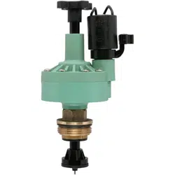
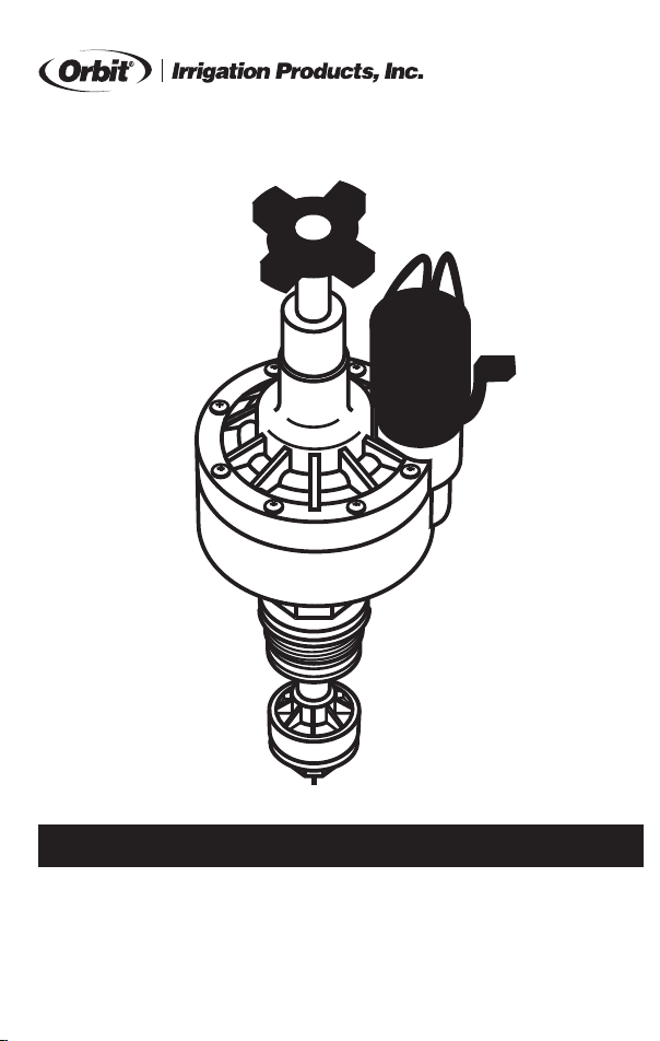
AUTOMATIC CONVERTER
MODEL 57029, 57030
The Automatic Converter converts manual sprinkler valves to automatic.
The Converter works with most 24-volt timers.
• Always check local codes before installing any sprinkler system.
• If static water pressure exceeds 80 PSI, a pressure regulator should be used.
ELECTRIC VALVE TROUBLE SHOOTING
PROBLEM: THE VALVE WILL NOT CLOSE
Check if... Solution:
1. Improper sizing.
Check that the proper-sized automatic valve was purchased for your size and brand
name of valve body. See conversion chart on reverse side.
2. Solenoid
plunger is stuck.
Turn off the water. Remove solenoid and clean out sand and debris. Be sure the plunger
and o-ring are in place when reassembling.
3. Worn seat in
valve body.
Turn off water. Remove the automatic converter and check that the lower seat of the
valve body is not worn or damaged.
4. Debris between
washer and
valve seat.
Turn off water. Remove the Automatic Converter Valve by turning the hex nut counter-
clockwise. Clean out any debris.
5. Diaphragm is
ruptured.
Turn off water. Replace Diaphragm Assembly.
PROBLEM: EXTERNAL VALVE LEAKS
Check if... Solution:
1. Pressure is
too high.
Install a pressure regulator valve and set at about 80 PSI.
2. Leaking around
screws.
Turn off the water. Undo the leaking screw 4 or 5 turns and retighten firmly.
3. Leaking below
solenoid.
Turn off the water. Tighten the solenoid.
4. Adapter o-ring
missing.
Turn off the water. If using the Adapter Ring, check that the o-ring is in place.
5. Hex Nut o-ring
missing.
Turn off the water. Check that the Hex Nut o-ring or gasket is in place and is not pinched
or otherwise unable to seal against the valve body.
6. The diaphragm
is split or torn.
Turn off the water. Remove cap and change the diaphragm.
7. Hex Nut is cross
threaded.
Turn off the water. Check that the Automatic Converter Hex Nut has been installed into
the valve body correctly. Attempt to reinstall the Automatic Converter into the valve
body. If the threads are stripped, replace the Hex Nut.
© 2014 Orbit
®
Irrigation Products, Inc.
All rights reserved. All trade names are registered
trademarks of respective manufacturers listed.
Orbit
®
Irrigation Products, Inc.
North Salt Lake, UT 84054 USA
www.orbitonline.com | 1-801-299-5555
INSTALLATION INSTRUCTIONS
1. REMOVE MANUAL STEM–Shut off the water supply and remove the manual valve stem,
leaving the valve body installed. Remove the o-ring or flat washer.
2. INSERT CONVERTER AND REASSEMBLE VALVE–Attach the automatic converter, making
sure the o-ring or gasket seals completely. When converting a brass anti-siphon valve, the
anti-siphon cover must be removed and replaced simultaneously with the converter. Make
sure the plunger and gasket are lined up correctly when replacing the anti-siphon cover.
Turn on the water supply and check assembly for leaks.
NOTES:
• Flow control must be fully open during installation to avoid damaging the valve
3. RUN THE WIRE–With the power off, connect the valve to an Orbit
®
timer (or other timer
that uses a UL
®
approved 24-volt class 2 transformer as a power source). Use a multi-
colored, multi-strand, jacketed sprinkler wire. Be sure the wire has at least one more
strand than the number of valves in the manifold. Trench and run the wire to the valves. It is
recommended, in areas that you will be frequently digging, that you use a section of PVC as
a protective covering.
4. ATTACH THE WIRE–Attach a colored wire to one wire on the solenoid and a common
wire to the other wire of the solenoid. It doesn’t matter which solenoid wire you use as the
common. Attach the colored wires to the corresponding zone terminal in the timer and the
common wire to the common connection of the timer. Use standard sprinkler wire (20 gauge)
for distances less than 800 feet and 18 gauge wire for over 800 feet. Use an Orbit
®
Grease Cap
and Wire Nut at each solenoid for a water-proof connection. Also water-proof any splices
made along the run.
5. CLOSE THE SPRINKLER VALVES–Turn the Manual Bleed Lever clockwise until closed.
Turn the water supply on. The valve should remain closed.
6. OPEN VALVES AND SET FLOW CONTROL–Turn the Manual Bleed Lever counter-clock-
wise to manually open the valve. Open the flow control to adjust the sprinkler heads to the
desired spray coverage. Then close the Manual Bleed Lever, the valve will shut off in a few
moments. The system is now ready to be controlled electrically from the controller or manu-
ally by opening the Manual Bleed Lever. NOTE: The flow control is not a positive shut-off.
DRAINING–In freezing areas, the valves and lines will need to be drained. Refer to the Orbit
®
Layout Guide or your local dealer to recommend proper drain points. To insure the electric
valves are completely drained in the fall, turn off the main sprinkler shut-off valve and electri-
cally run each valve dry for a few minutes. Turn the timer to the off position until spring.
CAUTION:
• If Static Water Pressure exceeds 80 PSI, a pressure regulator should be used.
• For outdoor use with cold water only: Do not use for indoor applications. Valves should be
placed so that water drains away from the house.
NOTES:
• Where possible, always protect valves with an Orbit
®
Valve Box and place gravel in the bottom.
PN 57029-32 rE
INSTRUCTIONS FOR OPERATION
ORBIT
®
IRRIGATION PRODUCTS, INC. • NORTH SALT LAKE, UTAH 84054

Your Orbit
®
Automatic Converter valve should provide years of trouble-free service.
However, if you do have any problems, try the following solutions.
PROBLEM: THE VALVE WILL NOT OPEN ELECTRICALLY
First, run the valve manually: Open the bleed lever (rotating it clockwise) and check to see that the flow control
is in the open position (Turn counter-clockwise). If the flow control is open and the valve still will not operate
electrically, check the following possibilities. (Close bleed lever when manual test is completed)
Check if... Solution:
1. Wiring is
correct.
Check the wiring at the valve and at the timer.
Check to see that the timer is working properly.
2. There is debris
in the port hole.
Turn off the water. Remove the solenoid. Push a wire or large paper clip down through
the round port hole working it up and down to free any debris. Be sure the plunger and
o-ring are in place when reassembling.
3. Solenoid plunger
is stuck.
Turn off the water. Remove solenoid and clean out any sand and debris. Be sure the
plunger and o-ring are in place when reassembling.
4. Defective
solenoid.
Turn off the water. Unscrew the solenoid and replace with one from a working valve. If
the valve now works, replace the solenoid. Be sure the plunger and o-ring are in place
when reassembling.
AUTOMATIC CONVERTER
MODEL 57029, 57030
The Automatic Converter converts manual sprinkler valves to automatic.
The Converter works with most 24-volt timers.
• Always check local codes before installing any sprinkler system.
• If static water pressure exceeds 80 PSI, a pressure regulator should be used.
ELECTRIC VALVE TROUBLE SHOOTING
PROBLEM: THE VALVE WILL NOT CLOSE
Check if... Solution:
1. Improper sizing.
Check that the proper-sized automatic valve was purchased for your size and brand
name of valve body. See conversion chart on reverse side.
2. Solenoid
plunger is stuck.
Turn off the water. Remove solenoid and clean out sand and debris. Be sure the plunger
and o-ring are in place when reassembling.
3. Worn seat in
valve body.
Turn off water. Remove the automatic converter and check that the lower seat of the
valve body is not worn or damaged.
4. Debris between
washer and
valve seat.
Turn off water. Remove the Automatic Converter Valve by turning the hex nut counter-
clockwise. Clean out any debris.
5. Diaphragm is
ruptured.
Turn off water. Replace Diaphragm Assembly.
PROBLEM: EXTERNAL VALVE LEAKS
Check if... Solution:
1. Pressure is
too high.
Install a pressure regulator valve and set at about 80 PSI.
2. Leaking around
screws.
Turn off the water. Undo the leaking screw 4 or 5 turns and retighten firmly.
3. Leaking below
solenoid.
Turn off the water. Tighten the solenoid.
4. Adapter o-ring
missing.
Turn off the water. If using the Adapter Ring, check that the o-ring is in place.
5. Hex Nut o-ring
missing.
Turn off the water. Check that the Hex Nut o-ring or gasket is in place and is not pinched
or otherwise unable to seal against the valve body.
6. The diaphragm
is split or torn.
Turn off the water. Remove cap and change the diaphragm.
7. Hex Nut is cross
threaded.
Turn off the water. Check that the Automatic Converter Hex Nut has been installed into
the valve body correctly. Attempt to reinstall the Automatic Converter into the valve
body. If the threads are stripped, replace the Hex Nut.
© 2014 Orbit
®
Irrigation Products, Inc.
All rights reserved. All trade names are registered
trademarks of respective manufacturers listed.
Orbit
®
Irrigation Products, Inc.
North Salt Lake, UT 84054 USA
www.orbitonline.com | 1-801-299-5555
INSTALLATION INSTRUCTIONS
1. REMOVE MANUAL STEM–Shut off the water supply and remove the manual valve stem,
leaving the valve body installed. Remove the o-ring or flat washer.
2. INSERT CONVERTER AND REASSEMBLE VALVE–Attach the automatic converter, making
sure the o-ring or gasket seals completely. When converting a brass anti-siphon valve, the
anti-siphon cover must be removed and replaced simultaneously with the converter. Make
sure the plunger and gasket are lined up correctly when replacing the anti-siphon cover.
Turn on the water supply and check assembly for leaks.
NOTES:
• Flow control must be fully open during installation to avoid damaging the valve
3. RUN THE WIRE–With the power off, connect the valve to an Orbit
®
timer (or other timer
that uses a UL
®
approved 24-volt class 2 transformer as a power source). Use a multi-
colored, multi-strand, jacketed sprinkler wire. Be sure the wire has at least one more
strand than the number of valves in the manifold. Trench and run the wire to the valves. It is
recommended, in areas that you will be frequently digging, that you use a section of PVC as
a protective covering.
4. ATTACH THE WIRE–Attach a colored wire to one wire on the solenoid and a common
wire to the other wire of the solenoid. It doesn’t matter which solenoid wire you use as the
common. Attach the colored wires to the corresponding zone terminal in the timer and the
common wire to the common connection of the timer. Use standard sprinkler wire (20 gauge)
for distances less than 800 feet and 18 gauge wire for over 800 feet. Use an Orbit
®
Grease Cap
and Wire Nut at each solenoid for a water-proof connection. Also water-proof any splices
made along the run.
5. CLOSE THE SPRINKLER VALVES–Turn the Manual Bleed Lever clockwise until closed.
Turn the water supply on. The valve should remain closed.
6. OPEN VALVES AND SET FLOW CONTROL–Turn the Manual Bleed Lever counter-clock-
wise to manually open the valve. Open the flow control to adjust the sprinkler heads to the
desired spray coverage. Then close the Manual Bleed Lever, the valve will shut off in a few
moments. The system is now ready to be controlled electrically from the controller or manu-
ally by opening the Manual Bleed Lever. NOTE: The flow control is not a positive shut-off.
DRAINING–In freezing areas, the valves and lines will need to be drained. Refer to the Orbit
®
Layout Guide or your local dealer to recommend proper drain points. To insure the electric
valves are completely drained in the fall, turn off the main sprinkler shut-off valve and electri-
cally run each valve dry for a few minutes. Turn the timer to the off position until spring.
CAUTION:
• If Static Water Pressure exceeds 80 PSI, a pressure regulator should be used.
• For outdoor use with cold water only: Do not use for indoor applications. Valves should be
placed so that water drains away from the house.
NOTES:
• Where possible, always protect valves with an Orbit
®
Valve Box and place gravel in the bottom.
PN 57029-32 rE
INSTRUCTIONS FOR OPERATION
ORBIT
®
IRRIGATION PRODUCTS, INC. • NORTH SALT LAKE, UTAH 84054
ORBIT
®
LIMITED 6 YEAR WARRANTY
Orbit
®
Irrigation Products, Inc. warrants to its customers that its Orbit
®
products will be free from defects in
materials and workmanship for a period of six years from the date of purchase. We will replace, free of charge,
the defective part or parts found to be defective under normal use and service for a period of up to six years after
purchase: proof of purchase is required. We reserve the right to inspect the defective part prior to replacement.
Orbit
®
Irrigation Products, Inc. will not be responsible for consequential or incidental cost or damage caused by
the product failure. Orbit
®
Irrigation Products, Inc. liability under this warranty is limited solely to the replacement
or repair of defective parts.
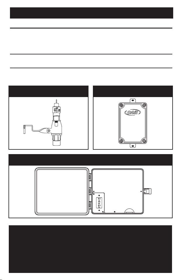
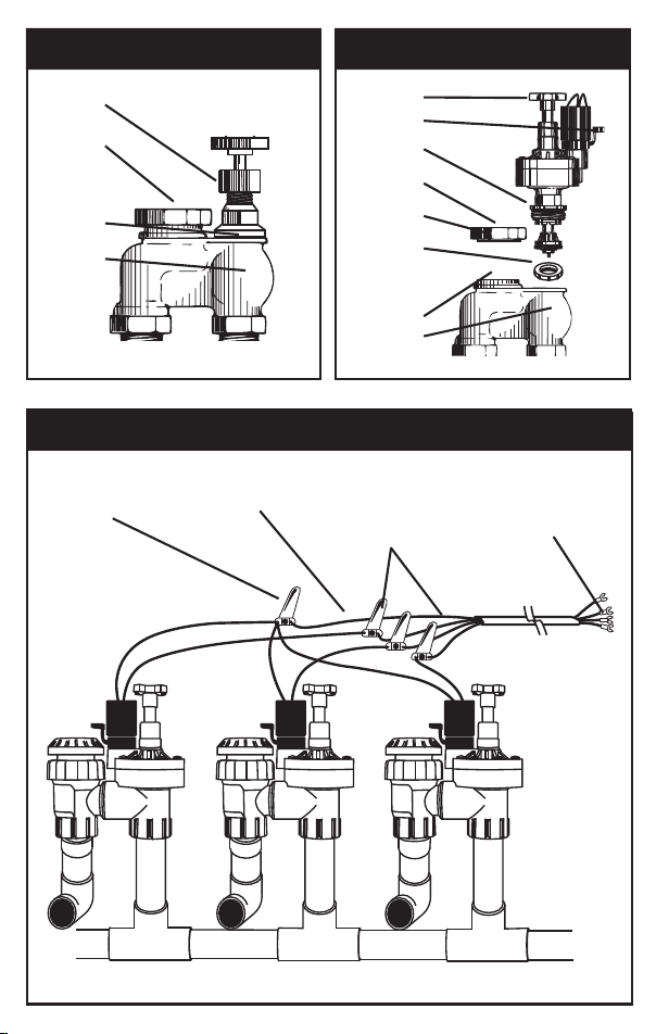
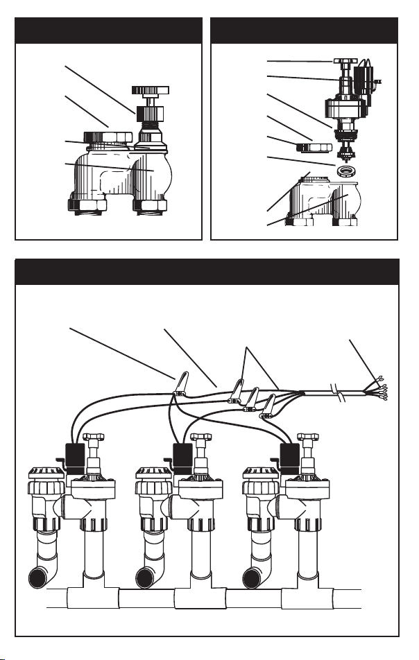
REPLACING THE MANUAL STEM
WITH THE CONVERTER
MANUAL VALVE
Manual
Valve Stem
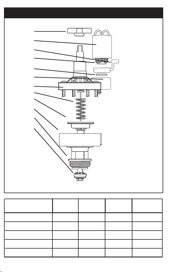
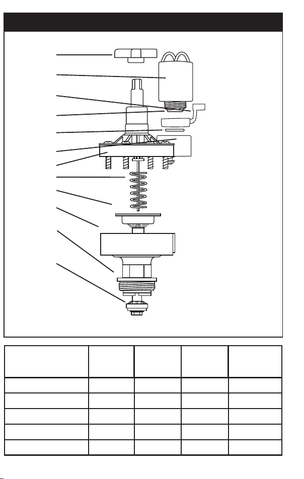
PARTS LISTING
Model 57030 includes a ring adapter required to convert most brands of manual valves to automatic.
Flow control
Handle
Electrical requirements are 18 Volts
A.C. minimum at the solenoid.
Inrush volt-amps
@24 V.A.C.= 5.5 VA
Inrush current
@24 V.A.C.= .35 AMPS
Holding current
@24 V.A.C.= .23 AMPS
Solenoid
Assembly 57041
Bleed Lever
Solenoid
Plunger
Solenoid
o-ring
Cover
Assembly
S.S. Screws
Spring
Diaphragm
Assembly
Body
Assembly
Hex Nut
Sub-Assembly
Seal Retainer
Sub-Assembly
WIRING THE CONVERTER TO THE TIMER
Valve Common
Connection
Single Common Wire
Out (to timer)
Grease Caps
and Station Wire
Connections
To Timer
Auto Converter brand
compatibility table
3/4"
Plastic
1"
Plastic
3/4"
Brass
1"
Brass
Orbit
®
57030 57030 57029 57030
Champion
®
57030 57030 57029 57030
Rainjet
®
57030 57030 - -
Rainbird
®
57030 57030 57029 57030
Richdel
®
/Lawn Genie
®
57030 57030 - -
OTHER ORBIT
®
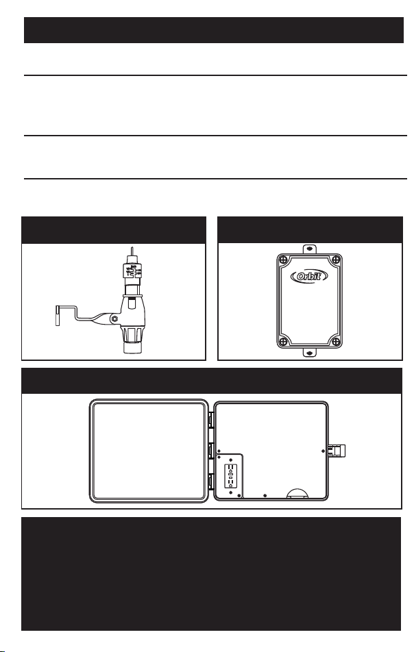
PRODUCTS
PRODUCT PART NUMBER BENEFIT/DESCRIPTION OF USE
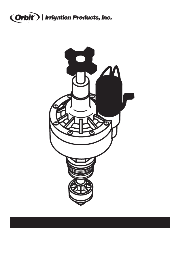
Automatic
Rain Shut-Off
57069 Automatically interrupts the watering cycle of
sprinkler timer when it rains and returns the timer
to automatic cycle when the water in the collecting
pan evaporates.
Weather
Resistant Box UL
®
57095 Allows outdoor installation of any brand of indoor
mount timer. It is UL
®
listed.
Pump Start Relay 57009 Automatically activates pump for automatic water-
ing (i.e. with well water).
Anti-Siphon
Cover
Flat Washer
Valve Body
Flow Control
Manual Bleed
Gasket or
o-ring
Anti-Siphon
Cover
Cover Flat
Washer
Adapter Ring:
Use when
converting
some plastic
manual valves.
Plunger
Valve Body
AUTOMATIC RAIN SHUT-OFF - 57069 PUMP START RELAY - 57009
WEATHER RESISTANT BOX UL
®
- 57095
ORBIT
®
LIMITED 6 YEAR WARRANTY
Orbit
®
Irrigation Products, Inc. warrants to its customers that its Orbit
®
products will be free from defects in
materials and workmanship for a period of six years from the date of purchase. We will replace, free of charge,
the defective part or parts found to be defective under normal use and service for a period of up to six years after
purchase: proof of purchase is required. We reserve the right to inspect the defective part prior to replacement.
Orbit
®
Irrigation Products, Inc. will not be responsible for consequential or incidental cost or damage caused by
the product failure. Orbit
®
Irrigation Products, Inc. liability under this warranty is limited solely to the replacement
or repair of defective parts.
REPLACING THE MANUAL STEM
WITH THE CONVERTER
MANUAL VALVE
Manual
Valve Stem
PARTS LISTING
Model 57030 includes a ring adapter required to convert most brands of manual valves to automatic.
Flow control
Handle
Electrical requirements are 18 Volts
A.C. minimum at the solenoid.
Inrush volt-amps
@24 V.A.C.= 5.5 VA
Inrush current
@24 V.A.C.= .35 AMPS
Holding current
@24 V.A.C.= .23 AMPS
Solenoid
Assembly 57041
Bleed Lever
Solenoid
Plunger
Solenoid
o-ring
Cover
Assembly
S.S. Screws
Spring
Diaphragm
Assembly
Body
Assembly
Hex Nut
Sub-Assembly
Seal Retainer
Sub-Assembly
WIRING THE CONVERTER TO THE TIMER
Valve Common
Connection
Single Common Wire
Out (to timer)
Grease Caps
and Station Wire
Connections
To Timer
Auto Converter brand
compatibility table
3/4"
Plastic
1"
Plastic
3/4"
Brass
1"
Brass
Orbit
®
57030 57030 57029 57030
Champion
®
57030 57030 57029 57030
Rainjet
®
57030 57030 - -
Rainbird
®
57030 57030 57029 57030
Richdel
®
/Lawn Genie
®
57030 57030 - -
OTHER ORBIT
®
PRODUCTS
PRODUCT PART NUMBER BENEFIT/DESCRIPTION OF USE
Automatic
Rain Shut-Off
57069 Automatically interrupts the watering cycle of
sprinkler timer when it rains and returns the timer
to automatic cycle when the water in the collecting
pan evaporates.
Weather
Resistant Box UL
®
57095 Allows outdoor installation of any brand of indoor
mount timer. It is UL
®
listed.
Pump Start Relay 57009 Automatically activates pump for automatic water-
ing (i.e. with well water).
Anti-Siphon
Cover
Flat Washer
Valve Body
Flow Control
Manual Bleed
Gasket or
o-ring
Anti-Siphon
Cover
Cover Flat
Washer
Adapter Ring:
Use when
converting
some plastic
manual valves.
Plunger
Valve Body
AUTOMATIC RAIN SHUT-OFF - 57069 PUMP START RELAY - 57009
WEATHER RESISTANT BOX UL
®
- 57095
CONVERTIDOR AUTOMÁ TICO
MODELOS 57029, 57030
El Convertidor Automático transforma las válvulas del aspersor de manuales a au-
tomáticas. El convertidor funciona con la mayoria de los programadores de 24 voltios.
• Siempre revise los códigos locales antes de instalar cualquier sistema de aspersión.
• Use un regulador de presión si la presión estática del agua supera las 80 libras por
pulgada cuadrada.
SOLUCIÓN DE PROBLEMAS DE LAS VÁLVULAS ELÉCTRICAS
PROBLEMA: LA VÁLVULA NO CIERRA
Compruebe si... Solución:
1. Las dimensiones son
incorrectas.
Asegúrese que haya comprado la válvula automática con las dimensiones correctas
para el tamaño y la marca del cuerpo de la válvula. Fíjese en la tablada conversiones
que se encuentra al reverso.
2. El pistón del solenoide
está atascado.
Quite el solenoide y lávalo para que no tenga arena ni desechos. Asegúrese que el pistón y la
compuerta O (O-ring) estén colocados debidamente cuando se vuelvan a montar.
3. El asiento del cuerpo de la
válvula está desgastado.
Cierre el agua. Saque el convertidor automático y asegúrese que el asiento inferior del
cuerpo de la válvula no esté desgastado o averiado.
4. Hay desechos entre la
arandela y el asiento
de la válvula.
Cierre el agua. Quite el válvula del Convertidor Automático porgirar la Tuerca Hexago-
nal en dirección contraria a las manecillas del reloj. Limpie la arena o basura que se
haya acummulado.
5. El diafragma está roto. Cierra el agua. Reemplace el montaje del diafragma.
PROBLEMA: HAY ESCAPE DE AGUA EN LA VÁLVULA EXTERNA
Comprueba si... Solution:
1. La presión es
demasiada alta.
Instale una válvula reguladora de presión y fije aproximadamete a 80 libras por pulgada
cuadrada.
2. Hay escape de agua
alrededor de los tornillos.
Cierre el agua. Afloje el tornillo de escape dando 4 ó 5 vueltas y vuelva a apretarlo bien.
3. Hay escape de agua
debajo del solenoide.
Cierre el agua. Ajuste el solenoide.
4. Le falta la compuerta O
del adaptador.
Cierra el agua. Si está usando el anillo adaptador, verifique que la compuerta O esté en
el lugar apropiado.
5. Le falta la tuerca
haxagonal de la
compuerta O
Cierra el agua. Asegúrese que la tuerca hexagonal de la compuerta O o el empaque
esté en el lugar debido y que no esté perforado o que de alguna manera no se pueda
sellar contra el cuerpo de la válvula.
6. El diafragma está roto
o desgarrado
Cierre el agua. Quite la tapa y cambie el diafragma.
7. La tuerca hexagonal
está mal enroscada
Cierra el agua. Compruebe que la Tuerca Hexagonal del convertidor automático haya
sido colocada correctamente en el cuerpo de la válvula. Trate de instalar otra vex el
convertidor automático en el cuerpo de la válvula. Reemplace la tuerca hexagonal si es
que la rosca está aislada.
© 2014 Orbit
®
Irrigation Products, Inc.
Todos los derechos son reservados. Todos los nombres
comerciales son marcas registradas de los listados
fabricantes respectivos.
Orbit
®
Irrigation Products, Inc.
North Salt Lake, UT 84054 USA
www.orbitonline.com | 1-801-299-5555
INSTRUCCIONES DE INSTALACIÓN
1. DESMONTE LA BASE MANUAL–Cierre el agua y desmonte la base de la válvula manual, de modo
que el cuerpo de la válvula quede instalado. Quite la arandela plana o compuerta O (O-ring).
2. INSERTE EL CONVERTIDOR Y VUELVA A ARMAR LA VÁLVULA–Coloque el convertidor automático
y asegúrese que el empaque o compuerta O quede sellado. Al momento de transformar una válvula
antisifón de bronce, quite la cubierta del antisifón y reemplácela junto con el convertidor. Asegúrese
que al reemplazar la cubierta del antisifón, tanto el pistón (plunger) como el empaque queden
correctamente alineados. Abra el suministro de agua y compruebe que no hayan escapes de agua en
el montaje.
NOTAS:
• El control de flujo debe estar totalmente abierto durante la instalación para evitar dañar la válvula.
3. INSTALE LOS CABLES–Con la energía apagada, conecta la válvula al programador Orbit® (o a
otro programador que use como fuente de energía principal un tranformador clase 2 de 24 voltios
aprobado por UL®). Use alambre para aspersores de varias hebras y forrado con aislantes de varios
colores. Percátese que el alambre tenga por lo menos una hebra más en comparación al número
de válvulas del sistema múltiple. Separe las hebras del alambre y conéctelas a las válvulas. Se
recomienda que use un tubo PVC, a manera de protector del alabre, en aquellas áreas donde tenga
pensado cabar frecuentemente.
4. CONECTE EL ALAMBRE–Conecte uno de los alambres de color a uno de los alambres del
solenoide y un alambre común a otro de los alambres del solenoide. Cualquiera de los alambres
del solenoide puede ser usado como el común. Conecte los alambres de color a los respectivos
terminales de zona del programador y el alambre común del programador. Use alambre stándard
para aspersores (calibre 20) para distancias de menos de 800 pies (244 metros) y calibre 18 para más
de 800 pies. Para proteger del agua, use una cápsula de grasa y tuerca de alambre empalmes a lo
largo de la conexión.
5. CIERRE LAS VÁLVULAS DEL ASPERSOR–Gire el tornillo de apertura manual en dirección de las
manecillas del reloj hasta que cierre. Al abrir el suministro de agua, la válvula deberá permanecer
cerrada.
6. ABRA LAS VÁLVULAS Y FIJE EL CONTROL DEL CAUDAL–Para abrir la válvula manualmente, gire
el tornillo de apertura manual en dirección contraria a las manecillas del reloj. Abra el control del
caudal para regular las cabezas del aspersor en relación al área que se desea regar. Luego cierre
el tornillo de apertura manual. La válvula se cerrará en breve. El sistema está ahora listo para ser
controlado electrónicamente, con el controlador, o manualmente, abriendo el tornillo de apertura
manual. NOTA: No es eficaz cerrar el sistema por medio del control del caudal.
DRENAJE–Se deben drenar las válvulas y las tuberías en aquellas áreas susceptibles al
congelamiento. Consulte la Guía esquemática del sistema Orbit
®
o a su ditribuidor local en cuanto a
los puntos apropiados de drenaje. Para asegurarse que las válvulas eléctricas estén completamente
vacías para el otoño, cierre la válvula princial que apaga (cierra) el aspersor y eléctricamente haga
funcionar, sin agua, cada válvula por unos instantes. Apague el programador hasta la primavera.
ADVERTENCIA:
• Use un regulador de presión, si la presión estática del agua sobrepasa las 80 libras por pulgada.
• Use sólo en áreas exteriores. No lo use en sistemas interiores. Las válvulas deben ser colocadas
en lugares donde el agua pueda ser drenada hacia afuera de la casa.
NOTAS:
• Donde sea posible, siempre proteja las válvulas con una caja de válvulas Orbit
®
y ponga piedrecil
las en el fondo de la caja.
INSTRUCCIONES DE MANEJO
ORBIT
®
IRRIGATION PRODUCTS, INC. • NORTH SALT LAKE, UTAH 84054
La Válvula del Convertidor Automático Orbit
®
debe de proporcionar muchos años de servicio libre de problemas.
Si tiene algún problema, trate las soluciones siguientes.
PROBLEMA: LA VÁLVULA NO ABRE ELECTRICAMENTE
Primero que todo, haga funcionar la válvula manualmente. Abra el tornillo de apertura manual y verifique que el
control del caudal esté en la posición abierta (gire en dirección contraria a las manecillas del reloj). Si el control
del caudal está abierto y la válvula todavía no funciona eléctricamente, pruebe las siquientes posibilidades.
(Cierre el tornillo de apertura manual una vez que haya terminado la prueba manual).
Compruebe si... Solución:
1. Se han conectado los
cables incorrectamente.
Examine los cables que conectan la válvula y el programador siguiendo las instructio-
nes. Fíjese si el programador funciona debidamente.
2. Hay desechos en el
orificio redondo.
Cierre el agua. Quite el solenoide. Inserta un cable o un clip de metal largo por el orifi-
cio redondo para asegurar que no esté atascado. Asegure que el pistón y la compuerta
O (O-ring) se hayan colocado en el lugar indicado cuande se vuelva a montar.
3. El pistón del solenoide
está atascado.
Cierre el agua. Quite el solenoide y limpie la arena o la basura que se hay acumulado.
Asegúrese que el pistón y la compuerta O (O-ring) estén colocados debidamente
cuando se vuelvan a montar.
4. El solenoide está
defectuoso.
Cierre el agua. Destornille el solenoide y cámbielo con uno de una válvula que ya esté funcio-
nado. Si la válvula funciona, substituya el solenoide defectuoso. Asegúrese que el pistón y la
compuerta O (O-ring) estén colocados debidamente cuando se vuelvan a montar.
GARANTÍA LIMITADA DE SEIS AÑOS DE ORBIT
®
Orbit
®
Irrigation Products, Inc. garantiza a sus clientes que sus productos Orbit
®
estarán libres de desperfectos
en material y mano de obra por un período de un año a partir de la fecha de compra. La compañia reemplazará,
sin cargo alguno, la parte o las partes que se compruebe que se han descompuesto debido al desgaste normal,
por un período máximo de un año a partir del momento de efectuada la compra. Orbit
®
Irrigation Products, Inc.
se reserva el derecho de inspeccionar la parte desompuesta antes de reemplazarla. La compañia no se hace
responsable de ningún costo de los daños causados por el malfuncionamiento del producto. La responsabilidad
de Orbit
®
Irrigation Products, Inc. dentro de los términos de esta garantía se limita unicamente al cambio o
reparación de las partes descompuestas.
REEMPLAZO DE LA BASE MANUAL
CON EL CONVERTIDOR
VÁLVULA MANUAL
Base de
la válvula
manual
LISTA DE PARTES
El modelo 57030 incluye un adaptador anillo requerido para transformar la mayoría
de los equipos que usan válvulas manuales a válvulas automáticas.
Manija para
el control
del caudal
El requerimiento eléctrico establ-
ece un mínimo de 18 voltios de CA
(corriente alterna) en el solenoide.
Entrada de voltamperios
@24 VCA = 5.5 VA (voltamperios)
Entrada de corriente
@24 VCA = .35 AMPS (amperios)
Corriente de retención
@24 VCA = .23 AMPS (amperios)
Núcleo del
solenoide
Apertura
manual
Pistón del
solenoide
Compuerta O
del solenoide
Cubierta del
montaje
Tornillos S.S.
H Muelle
Montaje del
diafragma
Montaje
del cuerpo
Detalle del
montaje de
la tuerca
hexagonal
Detalle del
montaje del
sujetador
hermético
CABLEADO DEL CONVERTIDOR AL PROGRAMADOR
Conexión a la
válvula común
Alambre común único
de salida (hacia el
programador)
Cápsulas de grasa
y estaciones de las
conexiones de alambre
Hacia el programador
Tabla de compatibi-
lidad para los equipos
autoconvertidores
3/4"
Plástico
1"
Plástico
3/4"
Bronce
1"
Bronce
Orbit
®
57030 57030 57029 57030
Champion
®
57030 57030 57029 57030
Rainjet
®
57030 57030 - -
Rainbird
®
57030 57030 57029 57030
Richdel
®
/Lawn Genie
®
57030 57030 - -
OTROS PRODUCTOS ORBIT
®
PRODUCTO NUMERO DE
LA PARTE
BENEFICIOS/DESCRIPCIÓN DEL USO
Apagador automático
en caso de lluvia
(sensor automático)
57069 Interrumpe automáticamente el ciclo de riego del
regulador de aspersores cuando llueve, y vuelve el
programador al ciclo automático cuand el agua que
se colecta en el recipiente especial se seca.
Caja a prueba de
inclemencias UL
®
57095 Permite que se instale al aire libre cualquier tipo
de regulador. Está de la lista UL
®
fabricado para el
montaje interior.
Relé de arranque
de bomba
57009 Activa automáticamente la bomba para el riego
automático (para los pozos de agua, por ejemplo).
Cubierta
antisifón
Arandela
plana
Cuerpo de
la válvula
Control del
caudal
Apertura
manual
Empaque o
compuerta O
Cubierta
antisifón
Cubierta de la
arandela plana
Anillo
adaptador:
(úselo para
transformar
ciertas válvu-
las manuales
plásticas).
Pistón
Cuerpo de
la válvula
APAGADOR AUTOMÁTICO EN CASO DE
LLUVIA (SENSOR AUTOMÁTICO) - 57069
RELÉ DE ARRANQUE DE BOMBA - 57009
CAJA A PRUEBA DE INCLEMENCIAS UL
®
- 57095