Your Orbit
®
Automatic Converter valve should provide years of trouble-free service.
However, if you do have any problems, try the following solutions.
PROBLEM: THE VALVE WILL NOT OPEN ELECTRICALLY
First, run the valve manually: Open the bleed lever (rotating it clockwise) and check to see that the flow control
is in the open position (Turn counter-clockwise). If the flow control is open and the valve still will not operate
electrically, check the following possibilities. (Close bleed lever when manual test is completed)
Check if... Solution:
1. Wiring is
correct.
Check the wiring at the valve and at the timer.
Check to see that the timer is working properly.
2. There is debris
in the port hole.
Turn off the water. Remove the solenoid. Push a wire or large paper clip down through
the round port hole working it up and down to free any debris. Be sure the plunger and
o-ring are in place when reassembling.
3. Solenoid plunger
is stuck.
Turn off the water. Remove solenoid and clean out any sand and debris. Be sure the
plunger and o-ring are in place when reassembling.
4. Defective
solenoid.
Turn off the water. Unscrew the solenoid and replace with one from a working valve. If
the valve now works, replace the solenoid. Be sure the plunger and o-ring are in place
when reassembling.
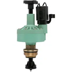
AUTOMATIC CONVERTER
MODEL 57029, 57030
The Automatic Converter converts manual sprinkler valves to automatic.
The Converter works with most 24-volt timers.
• Always check local codes before installing any sprinkler system.
• If static water pressure exceeds 80 PSI, a pressure regulator should be used.
ORBIT
®
LIMITED 6 YEAR WARRANTY
Orbit
®
Irrigation Products, Inc. warrants to its customers that its Orbit
®
products will be free from defects in
materials and workmanship for a period of six years from the date of purchase. We will replace, free of charge,
the defective part or parts found to be defective under normal use and service for a period of up to six years after
purchase: proof of purchase is required. We reserve the right to inspect the defective part prior to replacement.
Orbit
®
Irrigation Products, Inc. will not be responsible for consequential or incidental cost or damage caused by
the product failure. Orbit
®
Irrigation Products, Inc. liability under this warranty is limited solely to the replacement
or repair of defective parts.
ELECTRIC VALVE TROUBLE SHOOTING
PROBLEM: THE VALVE WILL NOT CLOSE
Check if... Solution:
1. Improper sizing.
Check that the proper-sized automatic valve was purchased for your size and brand
name of valve body. See conversion chart on reverse side.
2. Solenoid
plunger is stuck.
Turn off the water. Remove solenoid and clean out sand and debris. Be sure the plunger
and o-ring are in place when reassembling.
3. Worn seat in
valve body.
Turn off water. Remove the automatic converter and check that the lower seat of the
valve body is not worn or damaged.
4. Debris between
washer and
valve seat.
Turn off water. Remove the Automatic Converter Valve by turning the hex nut counter-
clockwise. Clean out any debris.
5. Diaphragm is
ruptured.
Turn off water. Replace Diaphragm Assembly.
PROBLEM: EXTERNAL VALVE LEAKS
Check if... Solution:
1. Pressure is
too high.
Install a pressure regulator valve and set at about 80 PSI.
2. Leaking around
screws.
Turn off the water. Undo the leaking screw 4 or 5 turns and retighten firmly.
3. Leaking below
solenoid.
Turn off the water. Tighten the solenoid.
4. Adapter o-ring
missing.
Turn off the water. If using the Adapter Ring, check that the o-ring is in place.
5. Hex Nut o-ring
missing.
Turn off the water. Check that the Hex Nut o-ring or gasket is in place and is not pinched
or otherwise unable to seal against the valve body.
6. The diaphragm
is split or torn.
Turn off the water. Remove cap and change the diaphragm.
7. Hex Nut is cross
threaded.
Turn off the water. Check that the Automatic Converter Hex Nut has been installed into
the valve body correctly. Attempt to reinstall the Automatic Converter into the valve
body. If the threads are stripped, replace the Hex Nut.
© 2007 Orbit
®
Irrigation Products, Inc.
All rights reserved. All trade names are registered
trademarks of respective manufacturers listed.
Orbit
®
Irrigation Products, Inc.
North Salt Lake, UT 84054 USA
www.orbitonline.com | 1-801-299-5555
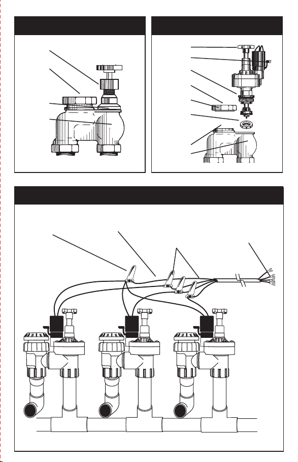
INSTALLATION INSTRUCTIONS
1. REMOVE MANUAL STEM–Shut off the water supply and remove the manual valve stem,
leaving the valve body installed. Remove the o-ring or flat washer.
2. INSERT CONVERTER AND REASSEMBLE VALVE–Attach the automatic converter, making
sure the o-ring or gasket seals completely. When converting a brass anti-siphon valve, the
anti-siphon cover must be removed and replaced simultaneously with the converter. Make
sure the plunger and gasket are lined up correctly when replacing the anti-siphon cover.
Turn on the water supply and check assembly for leaks.
3. RUN THE WIRE–With the power off, connect the valve to an Orbit
®
timer (or other timer
that uses a UL
®
approved 24-volt class 2 transformer as a power source). Use a multi-col-
ored, multi-strand, jacketed sprinkler wire. Be sure the wire has at least one more strand
than the number of valves in the manifold. Trench and run the wire to the valves. It is recom-
mended, in areas that you will be frequently digging, that you use a section of PVC as a
protective covering.
4. ATTACH THE WIRE–Attach a colored wire to one wire on the solenoid and a common
wire to the other wire of the solenoid. It doesn’t matter which solenoid wire you use as the
common. Attach the colored wires to the corresponding zone terminal in the timer and the
common wire to the common connection of the timer. Use standard sprinkler wire (20 gauge)
for distances less than 800 feet and 18 gauge wire for over 800 feet. Use an Orbit
®
Grease Cap
and Wire Nut at each solenoid for a water-proof connection. Also water-proof any splices
made along the run.
5. CLOSE THE SPRINKLER VALVES–Turn the Manual Bleed Lever clockwise until closed.
Turn the water supply on. The valve should remain closed.
6. OPEN VALVES AND SET FLOW CONTROL–Turn the Manual Bleed Lever counter-clock-
wise to manually open the valve. Open the flow control to adjust the sprinkler heads to the
desired spray coverage. Then close the Manual Bleed Lever, the valve will shut off in a few
moments. The system is now ready to be controlled electrically from the controller or manu-
ally by opening the Manual Bleed Lever. NOTE: The flow control is not a positive shut-off.
DRAINING–In freezing areas, the valves and lines will need to be drained. Refer to the Orbit
®
Layout Guide or your local dealer to recommend proper drain points. To insure the electric
valves are completely drained in the fall, turn off the main sprinkler shut-off valve and electri-
cally run each valve dry for a few minutes. Turn the timer to the off position until spring.
CAUTION:
• If Static Water Pressure exceeds 80 PSI, a pressure regulator should be used.
• For outdoor use with cold water only: Do not use for indoor applications. Valves should be
placed so that water drains away from the house.
NOTES:
• Where possible, always protect valves with an Orbit
®
Valve Box and place gravel in the bottom.
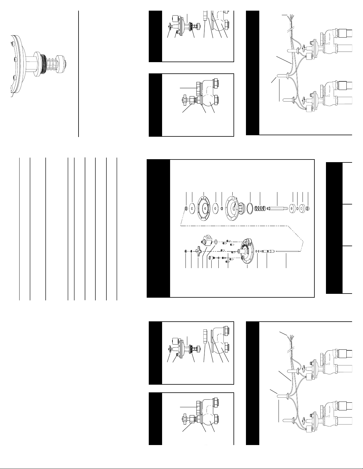
REPLACING THE MANUAL STEM
WITH THE CONVERTER
MANUAL VALVE
Manual
Valve Stem
PN 57029-32 Rev A
INSTRUCTIONS FOR OPERATION
ORBIT
®
IRRIGATION PRODUCTS, INC. • NORTH SALT LAKE, UTAH 84054
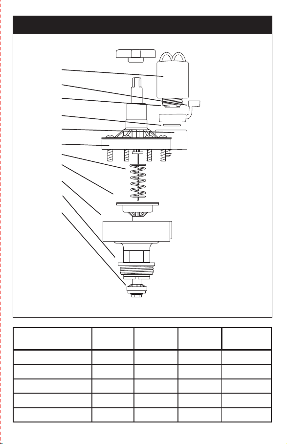
PARTS LISTING
Model 57030 includes a ring adapter required to convert most brands of manual valves to automatic.
Flow control
Handle
Electrical requirements are 18 Volts
A.C. minimum at the solenoid.
Inrush volt-amps
@24 V.A.C.= 5.5 VA
Inrush current
@24 V.A.C.= .35 AMPS
Holding current
@24 V.A.C.= .23 AMPS
Solenoid
Assembly 57041
Bleed Lever
Solenoid
Plunger
Solenoid
o-ring
Cover
Assembly
S.S. Screws
Spring
Diaphragm
Assembly
Body
Assembly
Hex Nut
Sub-Assembly
Seal Retainer
Sub-Assembly
WIRING THE CONVERTER TO THE TIMER
Valve Common
Connection
Single Common Wire
Out (to timer)
Grease Caps
and Station Wire
Connections
To Timer
Auto Converter brand
compatibility table
3/4"
Plastic
1"
Plastic
3/4"
Brass
1"
Brass
Orbit
®
57030 57030 57029 57030
Champion
®
57030 57030 57029 57030
Rainjet
®
57030 57030 - -
Rainbird
®
57030 57030 57029 57030
Richdel
®
/Lawn Genie
®
57030 57030 - -
PN 57029-32 REV B
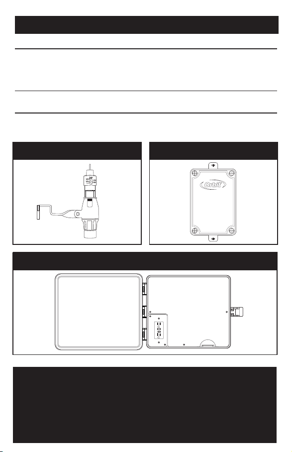
OTHER ORBIT
®
PRODUCTS
PRODUCT PART NUMBER BENEFIT/DESCRIPTION OF USE
Automatic
Rain Shut-Off
57069 Automatically interrupts the watering cycle of
sprinkler timer when it rains and returns the timer
to automatic cycle when the water in the collecting
pan evaporates.
Weather
Resistant Box UL
®
57095 Allows outdoor installation of any brand of indoor
mount timer. It is UL
®
listed.
Pump Start Relay 57009 Automatically activates pump for automatic water-
ing (i.e. with well water).
Anti-Siphon
Cover
Flat Washer
Valve Body
Flow Control
Manual Bleed
Gasket or
o-ring
Anti-Siphon
Cover
Cover Flat
Washer
Adapter Ring:
Use when
converting
some plastic
manual valves.
Plunger
Valve Body
p 801 295 9820
f 801 951 5815
www.fluid-studio.net
1065 South 500 West
Bountiful, Utah 84010
proof no: 5
date: 05.13.07
des: RA spck: RA
job no: 07WTM004005
client: ORBIT
sku: 57029
upc: NA
file name:
07WTM004005 57029-32 rB .indd
software: InDesign CS2
colors
additional instructions:
·
FOLD
non printing
PMS
????
PMS
????
color
non printing
PMS
????
Registration
BLACK
Printers are
responsible for
meeting print
production
requirements.
Any changes
must be approved
by the client and
Fluid Studio.
Printed piece
must meet
designated
specifications
on this form.
dimensions:
flat: w: 11" h: 11.4"
finished: w 5.7" h 3.67" d: 0"
AUTOMATIC RAIN SHUT-OFF - 57069 PUMP START RELAY - 57009
WEATHER RESISTANT BOX UL
®
- 57095

Your Orbit
®
Automatic Converter valve should provide years of trouble-free service.
However, if you do have any problems, try the following solutions.
PROBLEM: THE VALVE WILL NOT OPEN ELECTRICALLY
First, run the valve manually: Open the bleed lever (rotating it clockwise) and check to see that the flow control
is in the open position (Turn counter-clockwise). If the flow control is open and the valve still will not operate
electrically, check the following possibilities. (Close bleed lever when manual test is completed)
Check if... Solution:
1. Wiring is
correct.
Check the wiring at the valve and at the timer.
Check to see that the timer is working properly.
2. There is debris
in the port hole.
Turn off the water. Remove the solenoid. Push a wire or large paper clip down through
the round port hole working it up and down to free any debris. Be sure the plunger and
o-ring are in place when reassembling.
3. Solenoid plunger
is stuck.
Turn off the water. Remove solenoid and clean out any sand and debris. Be sure the
plunger and o-ring are in place when reassembling.
4. Defective
solenoid.
Turn off the water. Unscrew the solenoid and replace with one from a working valve. If
the valve now works, replace the solenoid. Be sure the plunger and o-ring are in place
when reassembling.
AUTOMATIC CONVERTER
MODEL 57029, 57030
The Automatic Converter converts manual sprinkler valves to automatic.
The Converter works with most 24-volt timers.
• Always check local codes before installing any sprinkler system.
• If static water pressure exceeds 80 PSI, a pressure regulator should be used.
ORBIT
®
LIMITED 6 YEAR WARRANTY
Orbit
®
Irrigation Products, Inc. warrants to its customers that its Orbit
®
products will be free from defects in
materials and workmanship for a period of six years from the date of purchase. We will replace, free of charge,
the defective part or parts found to be defective under normal use and service for a period of up to six years after
purchase: proof of purchase is required. We reserve the right to inspect the defective part prior to replacement.
Orbit
®
Irrigation Products, Inc. will not be responsible for consequential or incidental cost or damage caused by
the product failure. Orbit
®
Irrigation Products, Inc. liability under this warranty is limited solely to the replacement
or repair of defective parts.
ELECTRIC VALVE TROUBLE SHOOTING
PROBLEM: THE VALVE WILL NOT CLOSE
Check if... Solution:
1. Improper sizing.
Check that the proper-sized automatic valve was purchased for your size and brand
name of valve body. See conversion chart on reverse side.
2. Solenoid
plunger is stuck.
Turn off the water. Remove solenoid and clean out sand and debris. Be sure the plunger
and o-ring are in place when reassembling.
3. Worn seat in
valve body.
Turn off water. Remove the automatic converter and check that the lower seat of the
valve body is not worn or damaged.
4. Debris between
washer and
valve seat.
Turn off water. Remove the Automatic Converter Valve by turning the hex nut counter-
clockwise. Clean out any debris.
5. Diaphragm is
ruptured.
Turn off water. Replace Diaphragm Assembly.
PROBLEM: EXTERNAL VALVE LEAKS
Check if... Solution:
1. Pressure is
too high.
Install a pressure regulator valve and set at about 80 PSI.
2. Leaking around
screws.
Turn off the water. Undo the leaking screw 4 or 5 turns and retighten firmly.
3. Leaking below
solenoid.
Turn off the water. Tighten the solenoid.
4. Adapter o-ring
missing.
Turn off the water. If using the Adapter Ring, check that the o-ring is in place.
5. Hex Nut o-ring
missing.
Turn off the water. Check that the Hex Nut o-ring or gasket is in place and is not pinched
or otherwise unable to seal against the valve body.
6. The diaphragm
is split or torn.
Turn off the water. Remove cap and change the diaphragm.
7. Hex Nut is cross
threaded.
Turn off the water. Check that the Automatic Converter Hex Nut has been installed into
the valve body correctly. Attempt to reinstall the Automatic Converter into the valve
body. If the threads are stripped, replace the Hex Nut.
© 2007 Orbit
®
Irrigation Products, Inc.
All rights reserved. All trade names are registered
trademarks of respective manufacturers listed.
Orbit
®
Irrigation Products, Inc.
North Salt Lake, UT 84054 USA
www.orbitonline.com | 1-801-299-5555
INSTALLATION INSTRUCTIONS
1. REMOVE MANUAL STEM–Shut off the water supply and remove the manual valve stem,
leaving the valve body installed. Remove the o-ring or flat washer.
2. INSERT CONVERTER AND REASSEMBLE VALVE–Attach the automatic converter, making
sure the o-ring or gasket seals completely. When converting a brass anti-siphon valve, the
anti-siphon cover must be removed and replaced simultaneously with the converter. Make
sure the plunger and gasket are lined up correctly when replacing the anti-siphon cover.
Turn on the water supply and check assembly for leaks.
3. RUN THE WIRE–With the power off, connect the valve to an Orbit
®
timer (or other timer
that uses a UL
®
approved 24-volt class 2 transformer as a power source). Use a multi-col-
ored, multi-strand, jacketed sprinkler wire. Be sure the wire has at least one more strand
than the number of valves in the manifold. Trench and run the wire to the valves. It is recom-
mended, in areas that you will be frequently digging, that you use a section of PVC as a
protective covering.
4. ATTACH THE WIRE–Attach a colored wire to one wire on the solenoid and a common
wire to the other wire of the solenoid. It doesn’t matter which solenoid wire you use as the
common. Attach the colored wires to the corresponding zone terminal in the timer and the
common wire to the common connection of the timer. Use standard sprinkler wire (20 gauge)
for distances less than 800 feet and 18 gauge wire for over 800 feet. Use an Orbit
®
Grease Cap
and Wire Nut at each solenoid for a water-proof connection. Also water-proof any splices
made along the run.
5. CLOSE THE SPRINKLER VALVES–Turn the Manual Bleed Lever clockwise until closed.
Turn the water supply on. The valve should remain closed.
6. OPEN VALVES AND SET FLOW CONTROL–Turn the Manual Bleed Lever counter-clock-
wise to manually open the valve. Open the flow control to adjust the sprinkler heads to the
desired spray coverage. Then close the Manual Bleed Lever, the valve will shut off in a few
moments. The system is now ready to be controlled electrically from the controller or manu-
ally by opening the Manual Bleed Lever. NOTE: The flow control is not a positive shut-off.
DRAINING–In freezing areas, the valves and lines will need to be drained. Refer to the Orbit
®
Layout Guide or your local dealer to recommend proper drain points. To insure the electric
valves are completely drained in the fall, turn off the main sprinkler shut-off valve and electri-
cally run each valve dry for a few minutes. Turn the timer to the off position until spring.
CAUTION:
• If Static Water Pressure exceeds 80 PSI, a pressure regulator should be used.
• For outdoor use with cold water only: Do not use for indoor applications. Valves should be
placed so that water drains away from the house.
NOTES:
• Where possible, always protect valves with an Orbit
®
Valve Box and place gravel in the bottom.
REPLACING THE MANUAL STEM
WITH THE CONVERTER
MANUAL VALVE
Manual
Valve Stem
PN 57029-32 Rev A
INSTRUCTIONS FOR OPERATION
ORBIT
®
IRRIGATION PRODUCTS, INC. • NORTH SALT LAKE, UTAH 84054
PARTS LISTING
Model 57030 includes a ring adapter required to convert most brands of manual valves to automatic.
Flow control
Handle
Electrical requirements are 18 Volts
A.C. minimum at the solenoid.
Inrush volt-amps
@24 V.A.C.= 5.5 VA
Inrush current
@24 V.A.C.= .35 AMPS
Holding current
@24 V.A.C.= .23 AMPS
Solenoid
Assembly 57041
Bleed Lever
Solenoid
Plunger
Solenoid
o-ring
Cover
Assembly
S.S. Screws
Spring
Diaphragm
Assembly
Body
Assembly
Hex Nut
Sub-Assembly
Seal Retainer
Sub-Assembly
WIRING THE CONVERTER TO THE TIMER
Valve Common
Connection
Single Common Wire
Out (to timer)
Grease Caps
and Station Wire
Connections
To Timer
Auto Converter brand
compatibility table
3/4"
Plastic
1"
Plastic
3/4"
Brass
1"
Brass
Orbit
®
57030 57030 57029 57030
Champion
®
57030 57030 57029 57030
Rainjet
®
57030 57030 - -
Rainbird
®
57030 57030 57029 57030
Richdel
®
/Lawn Genie
®
57030 57030 - -
PN 57029-32 REV B
OTHER ORBIT
®
PRODUCTS
PRODUCT PART NUMBER BENEFIT/DESCRIPTION OF USE
Automatic
Rain Shut-Off
57069 Automatically interrupts the watering cycle of
sprinkler timer when it rains and returns the timer
to automatic cycle when the water in the collecting
pan evaporates.
Weather
Resistant Box UL
®
57095 Allows outdoor installation of any brand of indoor
mount timer. It is UL
®
listed.
Pump Start Relay 57009 Automatically activates pump for automatic water-
ing (i.e. with well water).
Anti-Siphon
Cover
Flat Washer
Valve Body
Flow Control
Manual Bleed
Gasket or
o-ring
Anti-Siphon
Cover
Cover Flat
Washer
Adapter Ring:
Use when
converting
some plastic
manual valves.
Plunger
Valve Body
p 801 295 9820
f 801 951 5815
www.fluid-studio.net
1065 South 500 West
Bountiful, Utah 84010
proof no: 5
date: 05.13.07
des: RA spck: RA
job no: 07WTM004005
client: ORBIT
sku: 57029
upc: NA
file name:
07WTM004005 57029-32 rB .indd
software: InDesign CS2
colors
additional instructions:
·
FOLD
non printing
PMS
????
PMS
????
color
non printing
PMS
????
Registration
BLACK
Printers are
responsible for
meeting print
production
requirements.
Any changes
must be approved
by the client and
Fluid Studio.
Printed piece
must meet
designated
specifications
on this form.
dimensions:
flat: w: 11" h: 11.4"
finished: w 5.7" h 3.67" d: 0"
AUTOMATIC RAIN SHUT-OFF - 57069 PUMP START RELAY - 57009
WEATHER RESISTANT BOX UL
®
- 57095