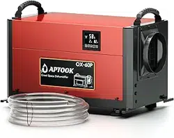

Model:OX-60PB
Please keep this manual carefully for further reference
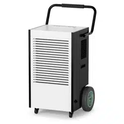
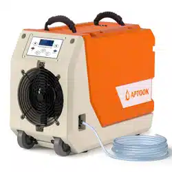
CRAWL SPACE DEHUMIDIFIER
USER MANUAL
R
Website:www.aptook.com
Email:[email protected]

CONTENT
INSTRUCTIONS...................................................................................................................1
BEFORE YOU BEGIN........................................................................................................2
IMPORTANT SAFETY TIPS...........................................................................................4
PRODUCT OVERVIEW.....................................................................................................8
OPERATION INSTRUCTION..........................................................................................9
INSTALLATION AND ASSEMBLY OF ACCESSORIES....................................11
DRAINAGE METHOD......................................................................................................17
CLEANING AND MAINTENANCE..............................................................................19
PART LIST..........................................................................................................................21
TROUBLESHOOTING....................................................................................................22
CUSTOMER SERVICE...................................................................................................23

1
INSTRUCTIONS
Thank you for choosing the dehumidifier by APTOOK!
We hope it will bring great convenience to your work and life. We recommend that you save the user
manual properly for future reference. Before using this product, please read the user manual carefully
to ensure that this product functions at its best.
The APTOOK's dehumidifier adopt an upgraded design, compact structure, easy to operate, and other
characteristics, widely used in scientific research, sanitation, commodity storage, underground
engineering, and dehumidification in high humidity places such as kitchens, bathrooms, archives,
warehouses, etc.
Can be effectively avoided telecommunications equipment, materials, etc, are damaged due to
dampness or rust.
Dehumidifier reduces humidity in enclosed environments by removing water vapor from the air.
The APTOOK OX-60PB,OX-80P,OX-100P is ideal for crawlspace drying, humidity control and
other applications.
Transportation and Custody
We are always just an email away
During transportation, this product should be handled preciously to prevent violent vibration. Generally,
the packaged product should not be stored in the open air for a long time. It should be placed in a
well-ventilated, non-corrosive gas warehouse. It should not be placed upside down. Set unit upright,
Always store, transport, and use the unit in a horizontal position. If the unit is ever placed in a vertical
position, return it to the horizontal position and let it stand for at least 24 hours before turning it on.
Rainproof measures should be adopted when stored temporarily.For best results, operate your dehumidifiers
in an enclosed area. Place your dehumidifier away from obstructions, and keep it away from anything that
could block airflow into and out of the unit.
We also kindly ask you to take a few minutes to register your product at www.aptook.com for
more efficient support.
To access customer support,please email to [email protected] with your purchase order ID to help us
address the problem fater and serve you better.
2
BEFORE YOU BEGIN
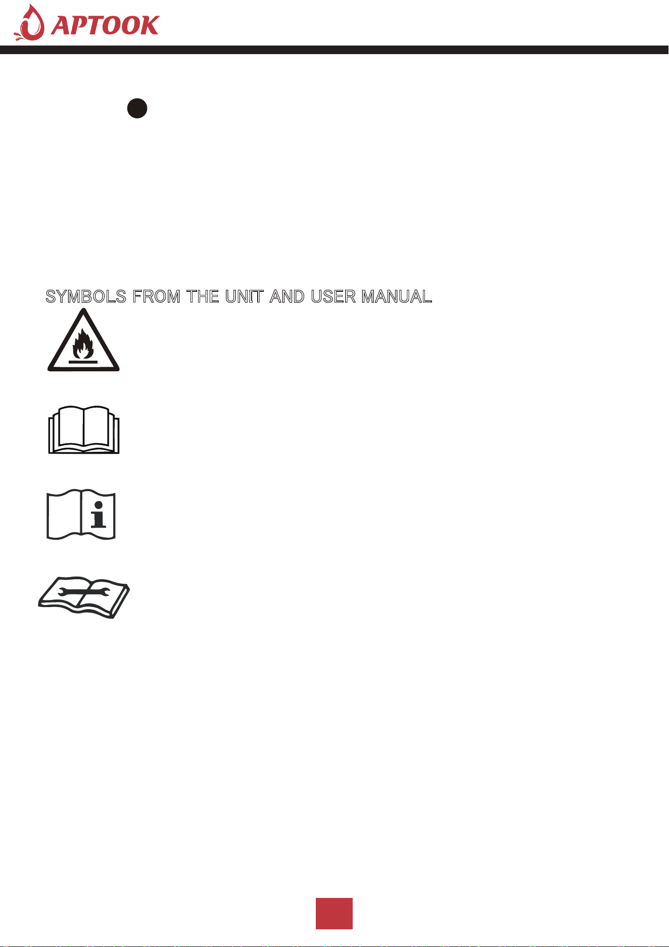
SYMBOLS FROM THE UNIT AND USER MANUAL
This restoration dehumidifier remove moisture of room . which commonly used in basement, warehouse,
villa and many so on.
The environmentally friendly R32 is used as the refrigerant. R32 has no damaging influence on the ozone
layer (ODP), a negligible greenhouse effect(GWP)and is available worldwide.Because of its efficient energy
properties,R32 is highly suitableas a coolant for this application.Precautions must be taken into
consideration due to the coolant's flammability.
The information contained herein is subject to change without notice.
The user manual contains instructions and notes on the operation and use of this unit.
APTOOK recommends that you use genuine accessories from APTOOK.
APTOOK shall not be responsible for any damage or expense that might result from the use of parts
other than genuine parts from the APTOOK.
Do not use unofficial components or accessories that may result in a risk of fire, electric shock, or injury
to persons. If you need to replace any components or accessories, please visit official APTOOK channels
to check relevant information.
For your safety and benefit, please read carefully before using and keep it handy for future reference.
This unit uses a flammable refrigerant.
If refrigerant leaks and comes in contact with fire or heating part,
it will create harmful gas and there is risk of fire.
Read the USER MANUAL carefully before operation.
Further information is available in the USER MANUAL, SERVICE
MANUAL, and the like.
Service personnel are required to carefully read the USER MANUAL and
SERVICE MANUAL before operation.

3
■ This appliance can be used by children aged from 8 years and above and persons with reduced
physical, sensory or mental capabilities or lack of experience and knowledge if they have been given
supervision or instruction concerning use of the appliance in a safe way and understand the hazards
involved. Children shall not play with the appliance. Cleaning and user maintenance shall not be made
by children without supervision.
■ This appliance is designed to use indoor ,not for outdoor.
■ The unit is designed only for use with R32(propane) gas as the designated refrigerant.
■ The refrigerant loop is sealed.Only a qualified technician should attempt to service!
■ Do not discharge the refrigerant into the atmosphere.
■ R32(propane)is flammable and heavier than air.
■ It collects first in low areas but can be circulated by the fans.
■ If propane gas is present or even suspected, donot allow untrained personnel to attempt to find
the cause.
■ The propane gas used in the unit has no odor.
■ The lack of smell does not indicate a lack of escaped gas.
■ If a leak is detected,immediately evacuate all persons from the store, ventilate the room and
contact the local fire department to advise them that a propane leak has occurred.
■ Do not let any persons back into the room until the qualified service technician has arrived and
that technician advises that it is safe to return to the room.
■ No open flames,cigarettes or other possible scurces of ignition should be used inside or in the
vicinity of the units.
■ Component parts are designed for propane andnon-incentive and non-sparking.
Component parts shall only be replaced with identical repair parts.
■ FAILURE TO ABIDE BY THIS WARNINGCOULD RESULT IN AN EXPLOSION,DEATH,
INJURY AND PROPERTY DAMAGE.

4
OPERATIONAL PRECAUTIONS
WARNING-to reduce the risk of fire,electric shock or injury to persons or property:
■ If the supply cord is damaged,it must be replaced by the manufacturer,its service agent or
similarly qualified persons in order to avoid a hazard.
The appliance shall be disconnected from its power source during service.
■ Always operate the unit from a power source of equal voltage,frequency and rating as indicated
on the product identification plate.
■ Always use a power outlet that is grounded.
■ Unplug the power cord when cleaning or when not in use.
■ Do not operate with wet hands.Prevent water from spilling onto the unit.
■ Do not immerse or expose the unit to rain,moisture or any other liquid.
■ Do not leave the unit running unattended.Do not tilt or turn over the unit.
■ Do not unplug while the unit is operating.
■ Do not unplug by pulling on the power cord.
■ Do not use an extension cord or an adapter plug.
■ Do not put objects on the unit.
■ Do not climb or sit on the unit.
■ Do not insert fingers or other objects into the air outlet.
■ Do not touch the air inlet or the aluminum fins of the wait.
■ Do not operate the unit if it is dropped, damaged or showing signs of product malfunction.
■ Do not clean the appliance with any chemicals.
■ Ensure the unit is far away from fire,inflammable,or explosive objects.
■ The unit shall be installed in accordance with national wiring regulations.
IMPORTANT SAFETY TIPS
Your safety is the most important thing we concerned!
Please read this manual carefully and fully understand before
operating your appliance.
WARNING
5
■ Do not use means to accelerate the defrosting process or to clean, other than those
recommended by the manufacture.
■ The appliance shall be stored in a room witllout continuously operation sources
(for cxample:open flames,an operating gas appliance or an operating electric heater).
■ The appliance shall be stored so as to prevent mechanical damage from occurring.
■ Do not piece or burn,even after use.
■ Be aware that refrigerants may not contain an odour.
■ Pipe-work shall be protected from physical damage and shall not be installed in an
unventilated space,if that space is smaller than 4 m².
■ Compliance with national gas regulations shall be observed.
■ Keep any required ventilation openings clear of obstruction.
■ The appliance shall be stored in a well-ventilated area where the room size
corresponds to the room area as specified for operation.
SAFETY PRECAUTIONS ON SERVICING
Please follow these warnings when to undertake the following when servicing an appliance
with R32.
1.Checks to the area
Prior to beginning work on systems containing flammable refrigerants,safety checks are
necessary to ensure that the risk of ignition is minimized. For repair to the refrigerating
system, the following precautions shall be complied with prior to conducting work on the
system.
2.Work procedure
Work shall be undertaken under a controlled procedure so as to minimize the risk of a
flammable gas or vapor being present while the work is being performed.
Any person who is involved with working on or breaking into a refrigerant circuit should hold
a current valid certificate from an industry-accredited assessment authority, which authorizes
their competence to handle refrigerants safely in accordance with an industry, recognized
assessment specification.
Servicing shall only be performed as recommended by the equipment manufacturer.
Maintenance and repair requiring the assistance of other skilled personnel shall be carried out
under the supervision of the person competent in the use of flammable refrigerants.
WARNING
WARNING

6
3.General work area
All maintenance staff and others working in the local area shall be instructed on the nature
of work being carried out. Work in confined spaces shall beavoided. The area around the work
space shall be sectioned off. Ensure that the conditions within the area have been made
safe by control of flammable material.
4.Checking for presence of refrigerant
The area shall be checked with an appropriate refrigerant detector prior to and during work,
to ensure the technician is aware of potentially flammable atmospheres. Ensure that the leak
detection equipment being used is suitable for use with flammable refrigerants,i.c.
no sparking,adequately sealed or intrinsically safe.
5.Presence of fire extinguisher
If any hot work is to be conducted on the refrigeration equipment or any associated parts,
appropriate fire extinguishing equipment shall be available to hand. Have a dry powder or
CO2 fire extinguisher adjacent to the charging area.
6.No ignition sources
No person carrying out work in relation to a refrigeration system which involves exposing
any pipe work that contains or has contained flammable refrigerant shall use any sources
of ignition in such a manner that it may lead to the risk of fire or explosion. All possible
ignition sources, including cigarette smoking,should be kept sufficiently far away from the
site of installation, repairing, removing and disposal, during which flammable refrigerant can
possibly be released to the surrounding space. Prior to work taking place, the area around
the equipment is to be surveyed to make sure that there are no flammable hazards or
ignition risks."No Smoking"signs shall be displayed.
7.Ventilated area
Ensure that the area is in the open or that it is adecquately ventilated before breaking into
the system or conducting any hot work.A degree of ventilation shall continue during the
period that the work is carried out. The ventilation should safely disperse any released
refrigerant and preferably expel it externally into the atmosphere.

7
8.Checks to the refrigeration equipment
Where electrical components are being changed,they shall be fit for the purpose and to the
correct specification. At all times the manufacturer's maintenance and service guidelines
shall be followed.If in doubt consult the manufacturer'stechnical department for assistance.
The following checks shall be applied to installations using flammable refrigerants:
-The charge size is in accordance with the room size within which the refrigerant containing
parts are installed;
-The ventilation machinery and outlets areoperating adequately and are not obstructed;
IMPORTANT SAFETY TIPS
'
HKXPLGLI\ &DSDFLW\
5+
3LQW'D\ 3LQW'D\ 3LQW'D\
3RZHU 6XSSO\
9a
+]
9a
+]
9a
+]
5DWHG ,QSXW 3RZHU &XUUHQW :$ $ $
0D[L ,QSXW 3RZHU &XUUHQW :$ :$ :$
5HIULJHUDQW &KDUJH
5R] 5R] 5 R]
1RLVH
G%$ G%$ G%$
/RZ 6LGH 3UHVVXUH 3VL 3VL 3VL
+LJK 6LGH 3UHVVXUH 3VL 3VL 3VL
%&6& $ $ $
&RPSUHVVRU ,QSXW
5/$$
/5$$
5
/$$
/5$$
5/$$
/5$$
)DQ 0RWRU 3RZHU $ +3 $ +3 $ +3
3URGXFW 'LPHQVLRQV LQFK
1HW :HLJKW
OEV OEV OEV
*URVV :HLJKW
OEV OEV OEV
SPECIFICATIONS
MODEL OX-60PB OX-80P OX-100P
8
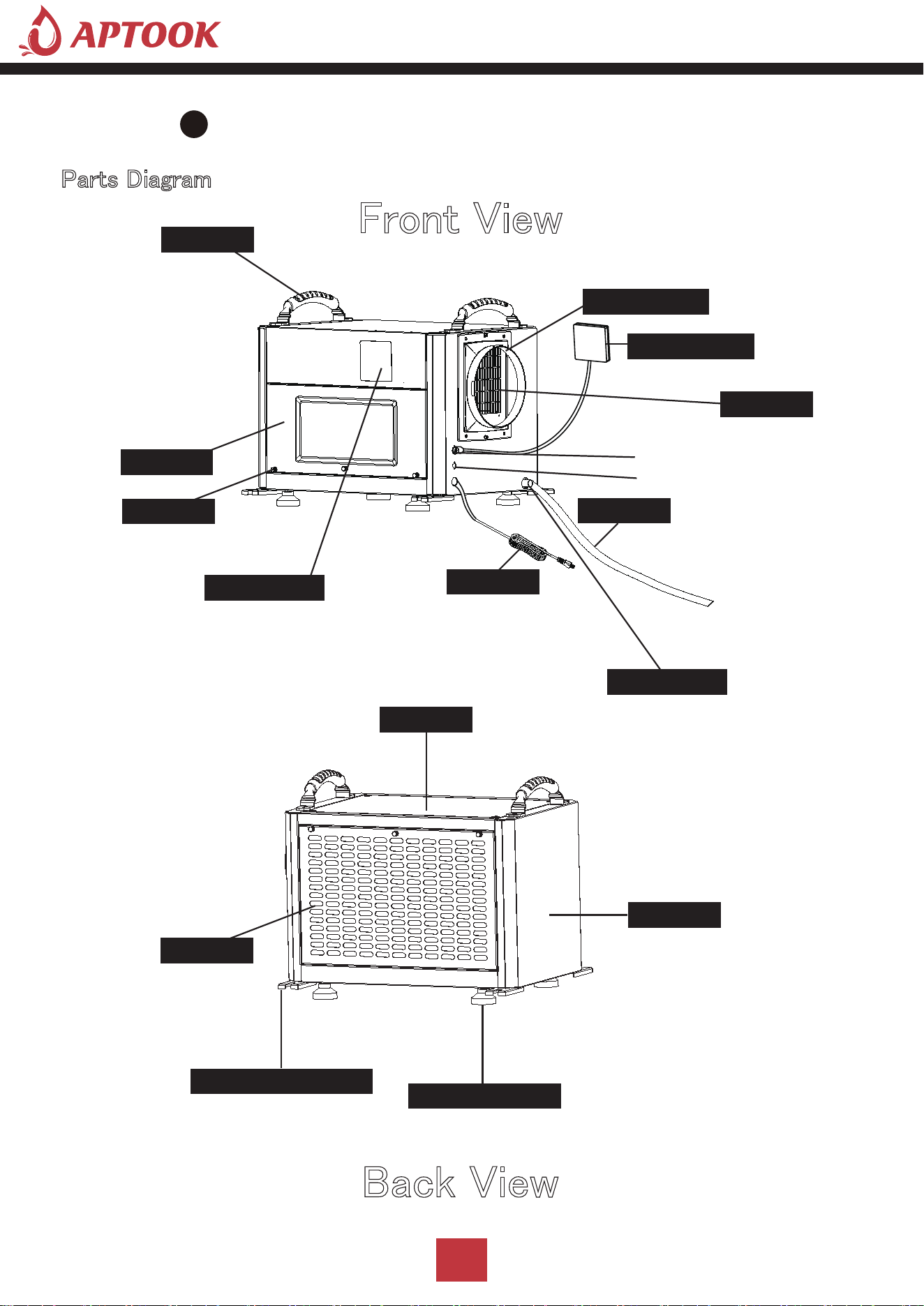
Parts Diagram
Front View
Back View
PRODUCT OVERVIEW
Power cord
Air outlet
Drain connect
Screws
Air inlet
Unit cover
Adjustable feet
Unit cover
Ceiling mount gasket
with removable filter
Acess door
Control panel
Water pipe
Remote control
Duct adapter
Handle
External pump signal cable interface
Control panel signal cable interface

9
A.On/Off(Power) Button
Press the on/off button and the machine will start running (one beep). Press the button again to the turn
the machine off. this button while on electric, screen light on, machine automatically goes to standby
mode,display screen shows environmental humidity.
Press the "mode" button, you can choose to working mode, auto mode/ continuously drying mode /
sleep mode, the corresponding mode lights on.
OPERATION INSTRUCTION
Button Description
Humidity Display
Timer Display
Sleep Mode
Continuously Drying Mode
Auto Mode
Timer Down On/Off
Up Mode Switch
Temperature Display
Water Full Alert
B.Mode Button
Timer/untimer can be set,while the machine is running, press the timer button light goes on, press
“+” “-” to set the time to stop the machine, or machine is on stop status, press the timer button
and press “+” “-” to set the time to open the machine.
C.Timer

10
D.ADD Button
Press this button to adjust the set humidity (20-90%) or timing time (0-24h) in an upward cycle.Press the
button for 3 seconds to switch between Fahrenheit and Celsius temperatures.Increase the humidity by
pressing this button at normal mode, humidity increase 1%RH with each press, buzzer rang each time with
the press, press the button for 1 second can increase the humidity continuously;
Press this button to down cycle to set humidity (20-90%) or timing time (0-24h).Press the
button for 3 seconds, then the temperature display will blink to display the coil temperature,
and the ambient temperature will still be displayed after 5 seconds.ecrease the humidity by
pressing this button at normal mode, humidity decrease 1%RH with each press, buzzer rang each time with
the press, press the button for 1 second can decrease the humidity continuously;
Environmental humidity>machine set humidity+3%, compressor, and fan start running.
Environmental humidity<machine set humidity+3%, the compressor stops, and the fan stops after a
delay of 5 seconds, and the compressor meets the three-minute delay protection.
The machine set humidity+3% ≤ environmental humidity ≤ machine set humidity+3%, and keeps running
in the original state.
The humidity cannot be adjusted, and the compressor can run continuously without being restricted
by the ambient humidity (to meet the three-minute delay protection of the compressor)
The setting humidity is adjustable (20%-90%), and the ambient humidity (20%-95%) is displayed after
the humidity setting is completed.
Default auto mode after on electric (default setting humidity 50%)
Press the mode button to select the continuously drying mode, and the light is on.
Press the mode button to select the sleep mode, and the light is on.
In sleep mode, if there is no button operation for 10 seconds, the display will enter a dark state.
If there is a button operation in sleep mode, it will return to normal display. After 10 seconds, if there
is no other button operation, it will continue to enter the dark display state.
In sleep mode, if there is a fault or the water is full, do not beep and the fault code will be
dimly displayed.
(Default humidity 60%, humidity adjustable)
Displays ambient humidity (20%-95%).
a)
a)
a)
b)
c)
b)
b)
E.Minus Button
1.Auto Mode
Operating Mode
2.Continuously Drying Mode
3.Sleep Mode

11
In auto mode or sleep mode, press the up and down adjustment button to cyclically adjust the set
humidity. Each time the up (or down) button is pressed, the set humidity will increase (or decrease)
by 1%.
During the adjustment of the set humidity, the set humidity will flash and display, after the adjustment
is completed, it will flash and display 5 times to confirm, and then switch to display the ambient humidity.
1. Intelligent defrosting: When a defrosting signal is detected, defrosting will start, and the corresponding
mode light will flash.
2. Timing function: can set timing/query timing/cancel timing
a) In the non-timing state: press the "timing" key to enter the timing setting state, the digital flashes to
display the timing time, and press the up and down keys to adjust the timing time (0~24h) during the
flashing period.
b) In the timing state: press the "timing" button, the timing time will be displayed by flashing, and press
the "timing" button again during the flashing to cancel the timing.
3. Water-full protection: When the water-full signal is detected, the water-full light is on and the digital
flashes to display "FL", the buzzer beeps 5 times to alarm, and the machine is turned off. After power
failure and drainage, resume normal operation.
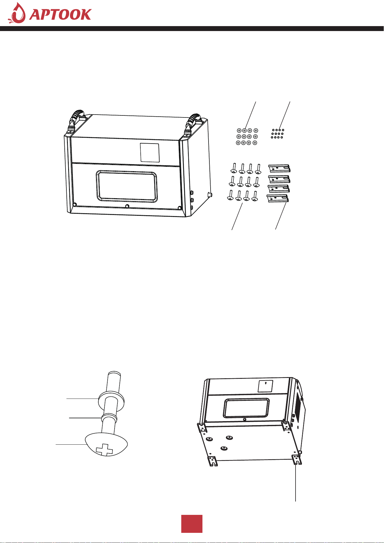
Ⅰ: Take out the accessories from the packing box: ceiling mount
gasket, screws
Humidity Control
Additional Function
Installation and assembly of accessories
Duct Adapter
Adapter Feet
12
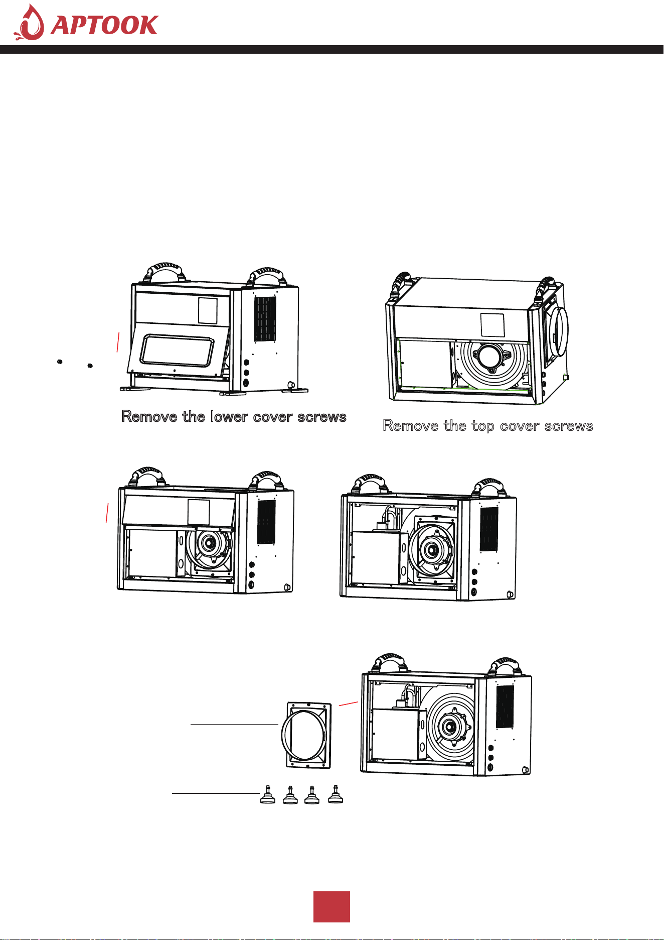
Ⅱ: Take out the duct adapter and adjustable rubber feet from the
machine body
1. Unscrew the 2 screws under the lower cover, and remove the lower front panel.
2. Use a screwdriver to remove the 2 screws on the top cover and remove the top front panel.
3. Take out the duct adapter and adjustable rubber feet from the machine body.
4. After the accessories are taken out, install the top front panel and lower front panel.
Remove the top cover screws
Remove the lower cover screws
Adjustable Nut
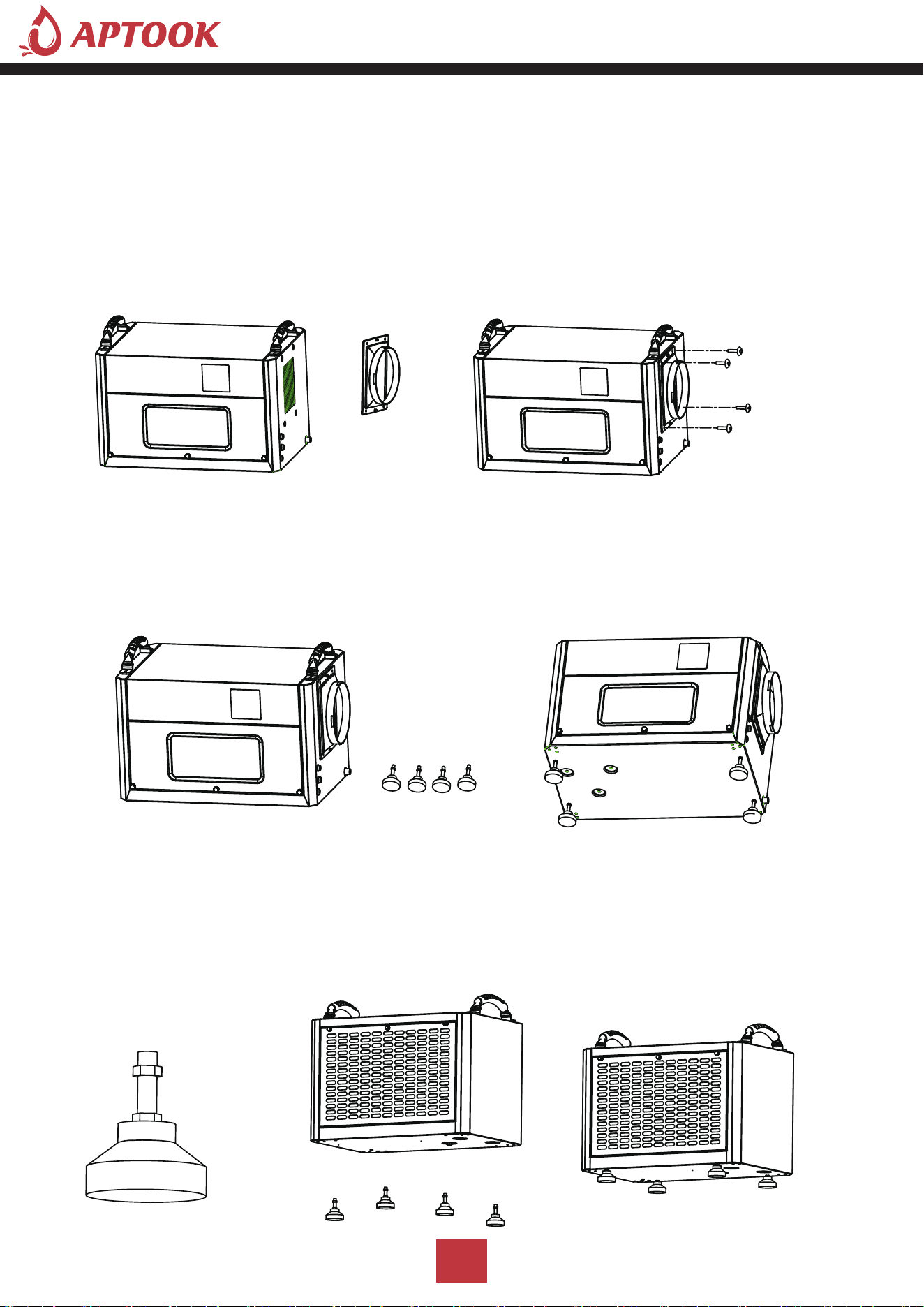
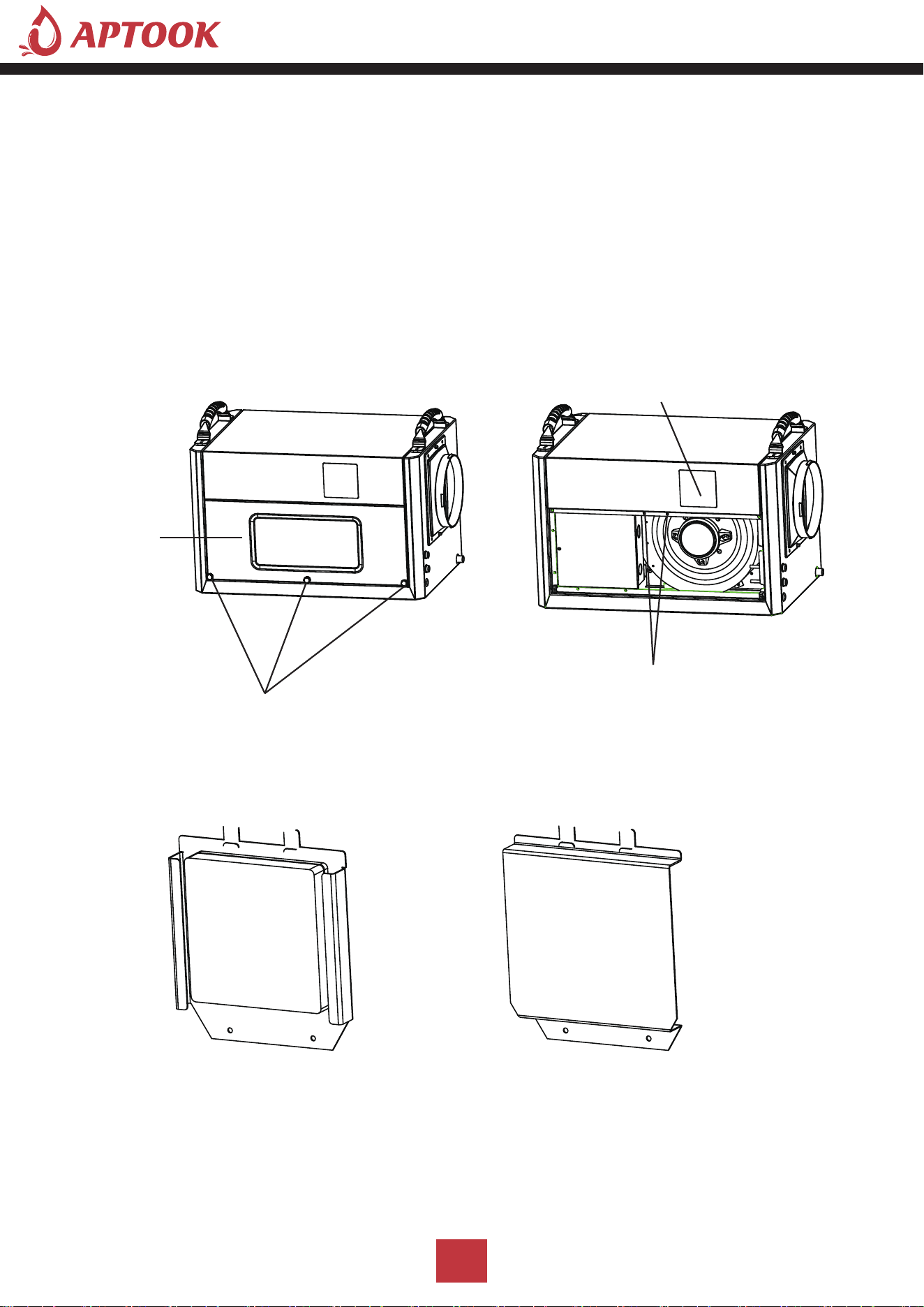
Ⅲ: Ducting installation
1. Align the duct adapter with the 4 screw positioning holes on the side.
2. Lock and fix the duct adapter with screws.
3. The user can put the exhaust pipe (purchased by the user according to the demand) on the duct
adapter, and it must be placed within the buckle position.
4.You can install the flex duct yourself,the duct adapter diameter is 6.88inch/17.5cm.
Ⅳ: Adjustable feet installation
When the machine is placed on the ground or used on some platforms, feets need to be installed
1. It is necessary to install 4 feets on the bottom plate of the body.
2. Adjust the height of the position adjustment nuts of the 4 feets to a suitable position
3. Assemble the 4 feets in the threaded holes on the bottom plate of the body respectively,
and lock tighten.
13
3. Assemble the 4 feets in the threaded holes on the bottom plate of the body respectively,
and lock tighten.
2. Adjust the height of the position adjustment nuts of the 4 feets to a suitable position.
Screws
Screws
Spring Spacers
Flat Spacers
Ceiling Mount Gaskets
Ceiling Mount Gaskets
Spring Spacers
Flat Spacers
Ⅴ: Ceiling mount gasket installation
When the machine is suspended in the air, the machine needs to be installed with ceiling mount gasket.
1. Install the ceiling mount gasket in the body (accessories: 4 ceiling mount gaskets, 12 spring spacers,
12 flat spacers, 12 screws)
2. 1 screw with 1 spring shim and 1 flat shim.
3. Screw the shimmed screw through the boom hole and screw it into the threaded hole on the base
plate of the machine and lock tighten.
4. Each ceiling mount gasket is installed with 3 screws, and the 4 ceiling mount gasket are assembled
on the bottom plate of the machine and locked tighten.
14
Handel Screws
Control Panel Assembly
Control Panel Hole Cover
Control Panel
Screws
Lower Cover
Ⅵ: Wall assembly method for control panel
When the machine is shipped, the control panel is assembled on the front of the machine.
In order to facilitate the user to install the control panel on the wall, the control panel needs to be
removed and the control panel installed on a wall surface that is convenient for operation, as follows.
1. Remove the 2 handel screws of the lower cover below the machine.
2. Pinch the handel screws in the middle of the front panel below with your hands and pull outward with
gentle force to pull the front panel apart.
3. screwdriver to screw down the 2 fixed screws and remove the control panel assembly, then install
the cover in the location of the control panel of the machine and fix it with 2 screws.
4. Remove the upper cover of the control panel assembly with a screwdriver; then remove the 2 screws
and remove the lower cover.
5. Mount the lower cover of the control panel assembly on a wall where it can be easily operated.
15
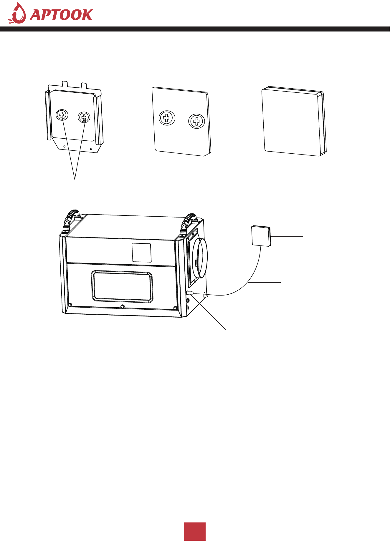
Control Panel
Signal Cable
Signal Cable Interface
Screws
6. Connect the signal wires to the terminals of the control panel inside the upper cover of the control
panel assembly, install them in place, and then fix the upper cover on the lower cover.
7. Then plug the other end of the signal cable of the control panel into the signal interface of the machine.
'HKXPLGLI\ &DSDFLW\
5+
3LQW'D\
3LQW'D\
3LQW'D\
3RZHU 6XSSO\
9a
+]
9a
+]
9a
+]
5DWHG ,QSXW 3RZHU &XUUHQW
:$
$
$
0D[L ,QSXW 3RZHU &XUUHQW
:$
:$
:$
5HIULJHUDQW &KDUJH
5R]
5R]
5 R]
1RLVH
G%$
G%$
G%$
/RZ 6LGH 3UHVVXUH
3VL
3VL
3VL
+LJK 6LGH 3UHVVXUH
3VL
3VL
3VL
%&6&
$
$
$
&RPSUHVVRU ,QSXW
5/$$
/5$$
5/$$
/5$$
5/$$
/5$$
)DQ 0RWRU 3RZHU
$ +3
$ +3
$ +3
3URGXFW 'LPHQVLRQV LQFK
1HW :HLJKW
OEV
OEV
OEV
*URVV :HLJKW
OEV
OEV
OEV
16
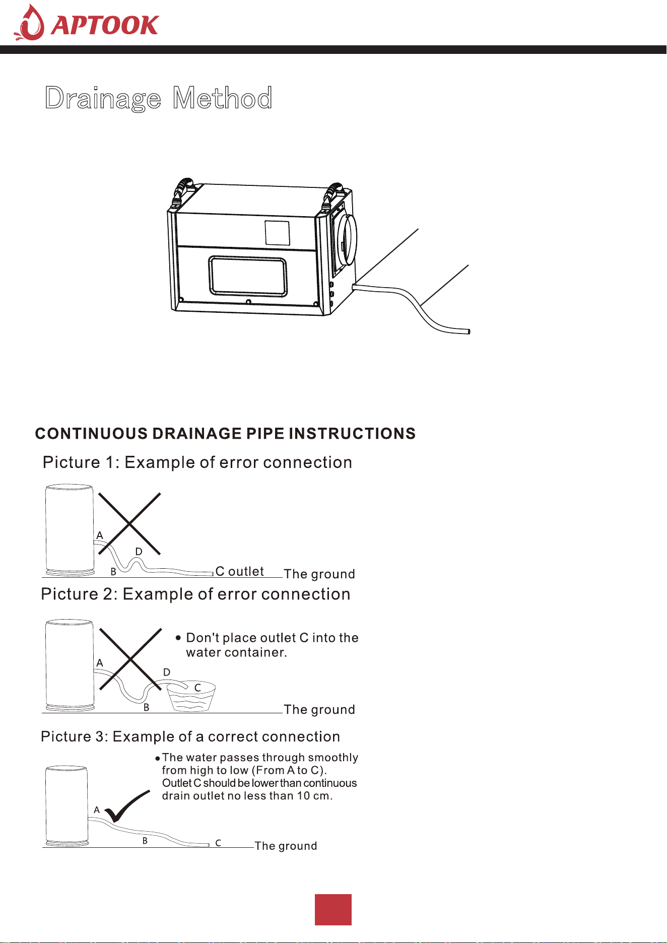
Drain outlet/External water pump inlet
Water Pipe
I: Water pipe drainage method
Operation instructions: When using the water pipe drainage method, connect the water pipe at the drain,
place the water pipe in place, place the other end of the water pipe at the drain, or at the drain sink,
or in the water storage container; turn on the machine to use the water pipe drainage method.
Dehumidifiers Adopt Drain by Gravity, the
collected condensation water can be drained
by gravity.When using gravity to drain:
1)Connect the drain hose to the Gravity
Drain Outlet;
2)Place the unattached end of the hose in
a suitable drainage facility. The drainage
facility should be lower than the drainoutlet
of the dehumidifier. (Ensure there are no
kinks or other obstructions that will stop
the water to flow.)
Note:
1)lf you use a bucket or other container
for water collection,check it regularly to
prevent overflows.2)Connecting a drain hose
that is too long is not recommended,as it
may cause water to back up, causing a leak.
3)lf the drain hose is too long, water may not
drain completely.which can lead to stagnant
water and mildew building up inside the hose.
4)Before moving the dehumidifier, make sure
the condensed water inside is completely
drained to avoid water leakage.
Drainage Method
17
Drain outlet/External water pump inlet
Water pipe A
Water pipe B
External pump signal cable interface
Water pump signal line
Water pump power cord
Water pump
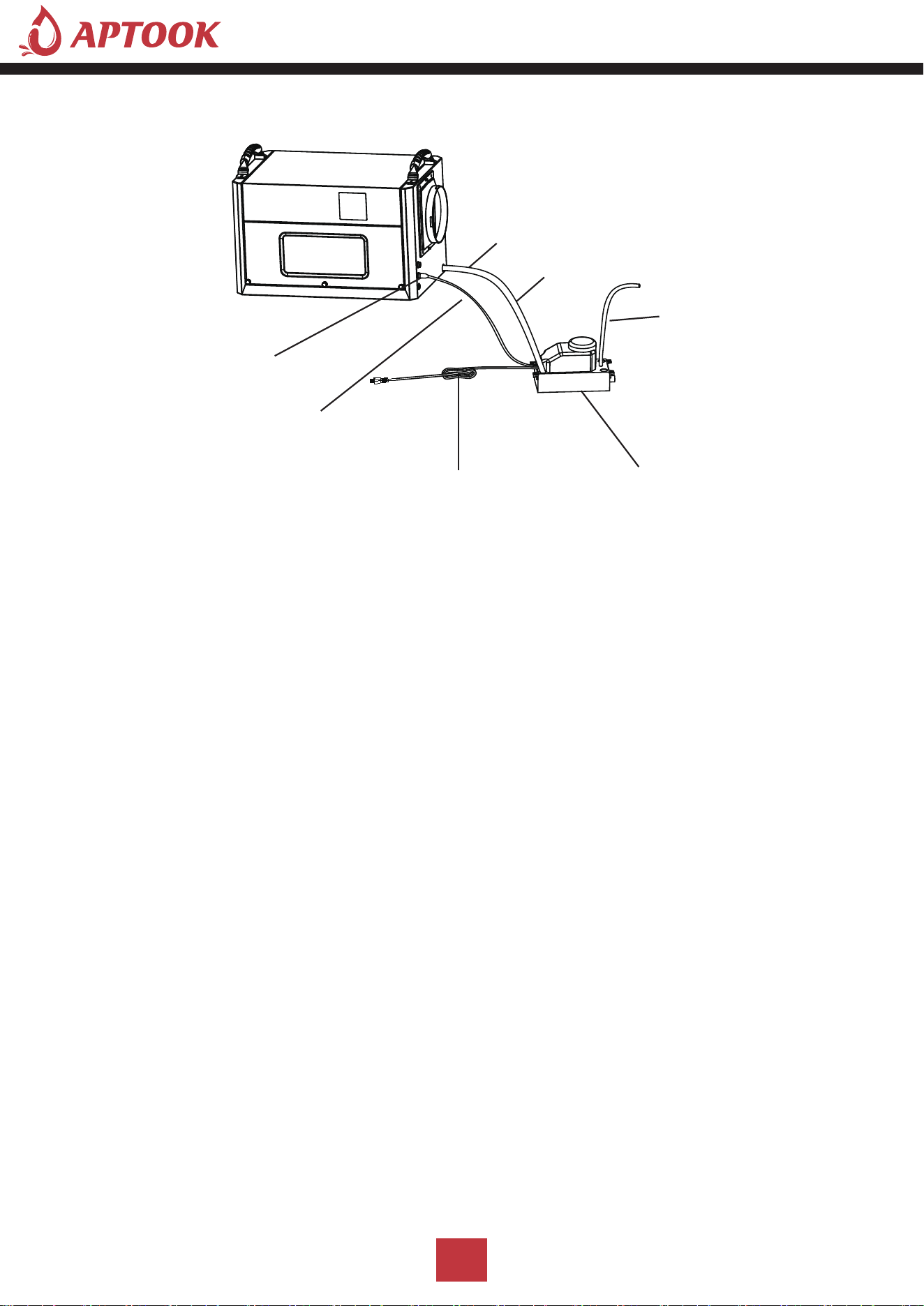
Ⅱ.External pump drainage method(not include pump,need to buy)
When it is necessary to connect an external water pump, oneend of the drainpipe is connected to the water
outlet, and theother end is connected to the water inlet of the water pump.
Note:The reserved external water pump signal input port cannot be connected to the power supply, so as
not to cause the main board ofthe product to burn out.
Vertical drainage available
Operating instructions: When using the pump drainage method, the operation is as follows.
1. The two ends of the water pipe A, one end connected to the machine drain, must be placed in place;
the other end placed in the water pump inlet, placed firmly.
2. Connect one end of the water pipe B to the water pump discharge port, and place the other end of the
water pipe in the sewer opening, or drainage sink, or water storage container; Note: the length of the water
pipe B must be within the range of the pump's head.
3. Plug one end of the pump signal line into the pump signal line interface of the machine and
assemble it in place.
4. Plug the power cord of the pump into a solid, suitable socket.Pump power on, turn on the machine
can be used to drain the water pump.
18
Cleaning and Maintenance
Cleaning :
Before doing any cleaning and maintenance work on the machine, the machine must be turned off,
unplugged, and no water should be spilled on the machine.
Use a soft, damp cloth to clean the casing. Do not use chemical solvents such as benzene, alcohol
or gasoline, otherwise, the machine casing will be damaged or even deformed.
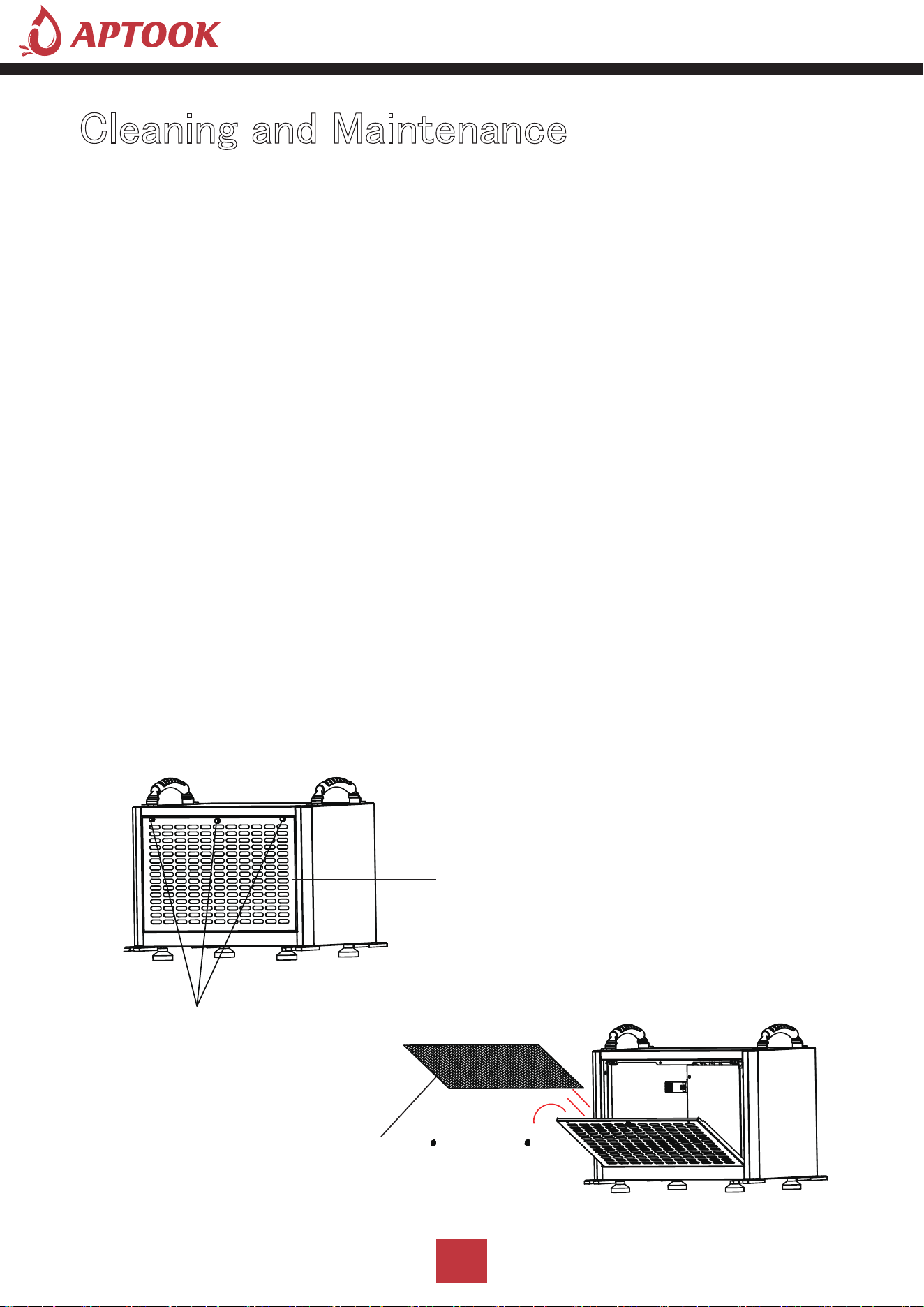
Filter cleaning:
The machine is equipped with a washable filter, it is recommended to clean the filter every 2 weeks.
If the filter is blocked by dust, it will reduce the efficiency of the machine.
1. Remove the filter
(1) Remove the handle screws on both sides above the air inlet frame.
(2) Pinch the handle screws in the middle above the air inlet frame with your hands, pull outward
with a little force, and pull the air inlet frame rotate (such as the rotating arrow)
(3).Remove the filter.
Handle Screws
Filter
Air Inlet Frame
I: Cleaning the filter.
Note: Before cleaning and maintaining the machine, please make
sure to turn off the machine and unplug it from the power source
to prevent electric shock.
19

2. Clean the filter
Use a vacuum cleaner to gently absorb the dust on the surface of the filter. If the filter is very dirty,
you can use tap water to rinse the filter, and completely cool and dry it, then put it back into the forward
air sheet, which can improve the performance of the machine.
Suggestion: Clean the filter once after every 3 months of use.
3. Assemble the filter and air inlet frame
(1) The filter will be put into the assembly of the air inlet frame buckle position, need to be assembled
in place.
(2) The air inlet frame will be held up with force, the air inlet frame will be rotated and assembled to the
machine inside, which must be assembled in place.
(3) Lock the handle screws on both sides above the air inlet frame to fix it.
Ⅱ. Machine body cleaning
Use a soft, slightly damp cloth to wipe the body.
Ⅲ. Machine storage
When you do not use this product for a long time and intend to store it, pay attention to the
following steps.
1. Drain the water from the machine body.
2. Tidy up the power cord.
3. Clean the filter.
4. Place it in a fresh and dry environment.
20
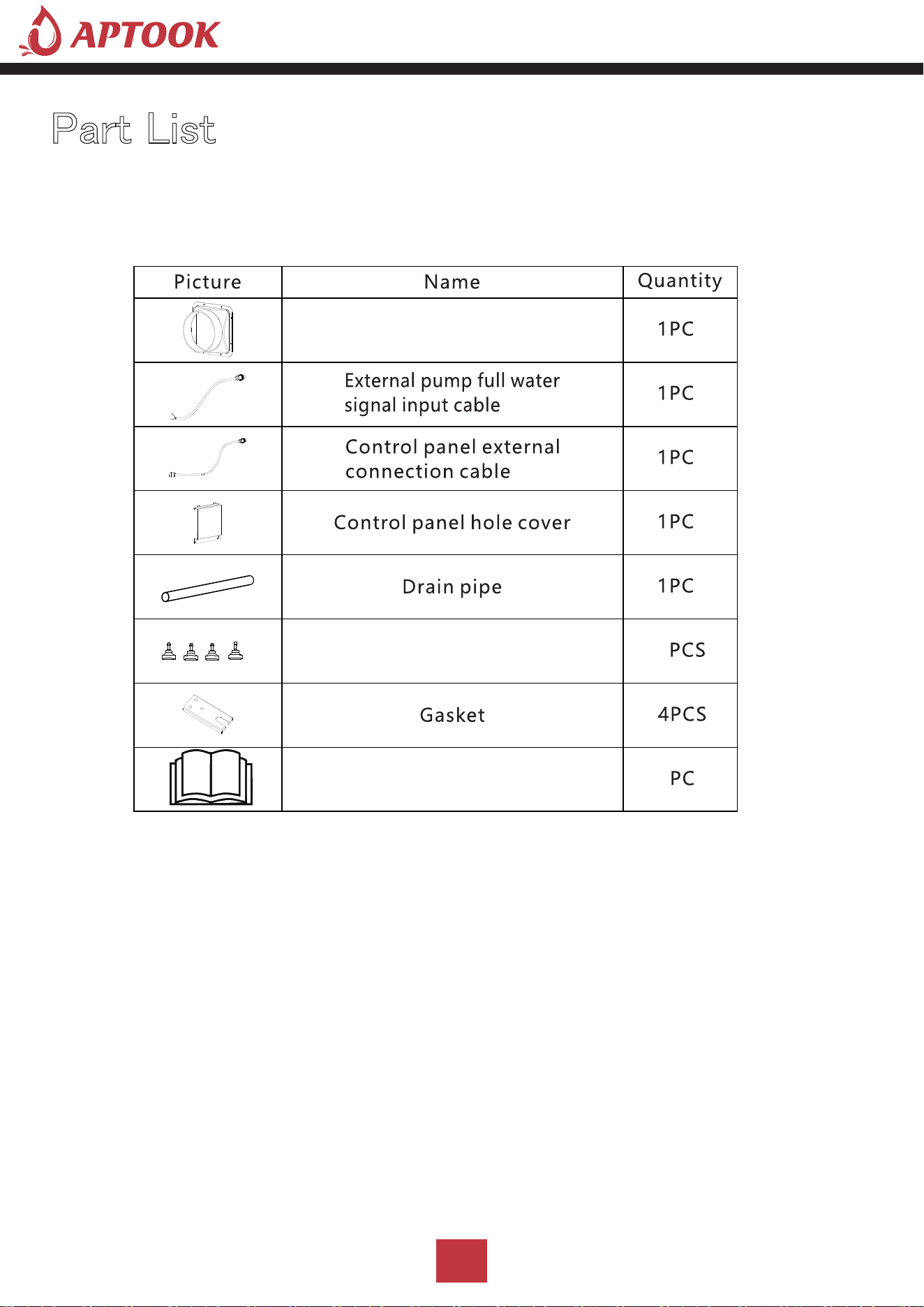
Part List
21
Dust adapter
User manual
Adjustable feet
4
4
1

Troubleshooting
Symptom Cause Solution
Machine Won't
Run
Power outage Restoration of power supply
Power plug is not connected
well
Connect the plug to the socket
Room temperature over 113 ℉
or below 38℉
The machine's protection device is
activated so that the machine d oes not
run
Low Air Flow
Filter with dirt accumulation
Cleaning filters
The air inlet or outlet is blocked Remove obstructions
Refrigerant leakage Contact agent or manufacturer for repair
Water Leakage Clogged outlet pipe
Remove the panel to remove the
blockage at the water pipe, or water
outlet
Loud Noise
Machine Is Not level
Move the dehumidifier to flat, firm
ground
Filter Mesh is Blocked
Clean the filter mesh according
toinstructions listed in manua l
Trouble Code:E1
Temperature and humidity
sensor failure
Check, or replace the temperature and
humidity sensor
Trouble Code:E2 Coil sensor failure Check, or replace the co il sensor
Trouble Code:CL
When the ambient temperature Tr< 36℉, "CL" will be displayed
and the compressor will stop immediately, and the fan delay will be
executed according to th e set value (F1 default 0, delay 5 seconds to stop).
When the ambient temperature rises t o ≥ 39℉, normal operation will
resume.
Trouble Code:CH
When the ambient temperature Tr> 113℉, "CH" will be
displayed, the compressor will stop immediately, and t he fan delay will be
executed according to th e set value (F1 default 0, delay 5 seconds to stop);
when the ring temperatu re ≤ 108℉, normal operation will be resumed.
Trouble Code:L0
When the ambient hu midity Hr< 20%, "LO" will be displayed, the
compressor will stop immediately, and the fan delay will be executed
according to the set value (F1 default 0, delay 5 seconds to stop). After the
humidity rises > 20%, resume normal work.
Trouble Code:HI
When the ambient humidity Hr>95%, "HI" is displayed and the
compressor and fan work normally.
After the humidity falls back to <95%, it will resume normal operation.
22

Customer Service
APTOOK offers a limited 1-year free warranty on these crawl space dehumidifiers,with original proof
of purchase(typically you maybe only requested to offer the order number or other information to prove
a genuine purchase,instead of an invoice) and where a defect has arisen, wholly or substantially, as a result
of faulty manufacture,parts or workmanship during the warranty period.
During the warranty period,for the damaged part, we will provide a replacement part if it can be restored
to normal use by replacing parts.
The warranty does not apply where damage is caused by other factors,including without limitation.
Normal wear and tear;
Abuse,mishandling, accident, or failure to follow operating instructions;
Exposure to liquid or infiltration of foreign particles;
Servicing or modifications of the product other than by APTOOK;
We will try our best to inspect the dehumidifier through photos or videos to troubleshoot and ensure
that we can better solve the problem for you.
These are our general terms for warranty service, but we always urge our customers to reach out to
us with any issue, regardless of warranty terms.
If you have an issue with a APTOOK product, please contact us at [email protected],and we will
do our best to resolve it for you.
Email
23