FUSION SERVICE REFRIGERATED DISPLAY CASES
> REMOTE UNITS WITH VERTICAL FRONT HINGED GLASS
> LOCKING HARDWARE FOR FRONT GLASS
> VERTICAL & ANGLED REAR SLIDING DOORS
REV H DATE: 07/11/2023 USER MANUALS\20-57746_FUSION_USER MANUAL_GHSV(L)(H)RLB_REF_SVC_VERT’L FRT GLASS_CASE
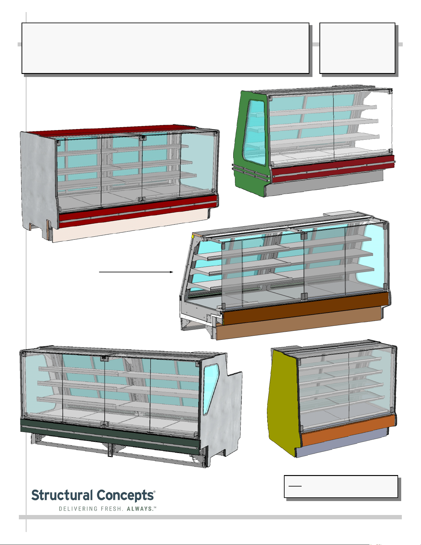
Model GHSV852RLB
Model GHSV852RLB.6677B (Front Toe-Kick
Removed For Illustrative Purposes Only)
Model GHSV652RLB.6677C
Note: See Next Page For Models That
Are Represented By This Manual.
Model GHSV852RLB.6856D
(Front-Left Adjoinment /
Varying Size Front Glass)
Model GHSV556RLB
SCC P/N
20-57746
USER
MANUAL
FUSION
CAREFULLY FOLLOW THESE INSTRUCTIONS
Structural Concepts Corp. ∙ 888 E. Porter Rd ∙ Muskegon, MI 49441 Phone: 231.798.8888 Fax: 231.798.4960 ∙ www.structuralconcepts.com
2
TABLE OF CONTENTS
TABLE OF CONTENTS ………………………………………………………………………………………..
OVERVIEW / TYPE / COMPLIANCE / WARNINGS / PRECAUTIONS / WIRING / PLUGS ..………….
INSTALLATION: REMOVAL FROM SKID, REMOVING LOWER FRONT PANELS ..……...…….…….
INSTALLATION, CONT’D: BOLTING AND SEALING UNITS TOGETHER ……………………………...
INSTALLATION, CONT’D: ELECTRICAL LAYOUT ………………………………………………………...
INSTALLATION, CONT’D: FRONT FAN ACCESS ………………………………………..………………..
INSTALLATION, CONT’D: FRAME SUPPORT RAILS / SEALING TO FLOOR ………………………...
INSTALLATION, CONT’D: FRONT GLASS ALIGNMENT & ADJUSTMENT - RAILS / LEVELERS ….
INSTALLATION, CONT’D: REFRIGERATION LINES / STUB-UPS / DRAINS / WIRING DIAGRAMS
INSTALLATION, CONT’D: SCALE STAND / OUTLETS / CAT-5 RECEPTACLE ……………………….
INSTALLATION, CONT’D: DISPLAY CASE START-UP .………………………………………………….
MAINTENANCE: LED LIGHT REMOVAL/REPLACEMENT, PLUG/CORD CONNECTION …………...
MAINTENANCE, CONT’D: DRAIN / TXV / REFRIGERATION LINES / SOLENOID / EVAP. FANS ….
MAINTENANCE FUNDAMENTALS - REAR SLIDING DOORS / THERMOMETER …………………....
MAINTENANCE FUNDAMENTALS - HINGED FRONT DOORS WITH LOCKING MECHANISM
(MODEL GHSV852RLB SHOWN, BUT IS APPLICABLE TO OTHER MODELS) ……………...
GENERAL CLEANING (TO BE PERFORMED BY STORE PERSONNEL) ………………..……...…….
TROUBLESHOOTING (TO BE PERFORMED BY STORE PERSONNEL) ..………..…….……….…….
GENERAL CLEANING (TO BE PERFORMED BY TRAINED SERVICE PROVIDERS ONLY) ………..
TROUBLESHOOTING (TO BE PERFORMED BY TRAINED SERVICE PROVIDERS ONLY) ………..
PREVENTIVE MAINTENANCE (TO BE PERFORMED BY TRAINED SERVICE PROVIDER)………..
SERIAL LABEL INFORMATION & LOCATION ..……………………………………...…....…………...…..
TECHNICAL SERVICE CONTACT INFORMATION / WARRANTY INFORMATION ...……….……......
2
3-4
5
6
7
8
9
10
11
12
13
14
15
16
17
18
19
20
21-23
24
25
26
Note: This Manual Is Applicable To Models GHSV452RLB / GHSV456RLB / GHSV556RLB /
GHSV652RLB.6677C / GHSV652RLB.6868C / GHSV852RLB / GHSV852RLB.6745D /
GHSV852RLB.6677B / GHSV852RLB.6856D / GHSV1052RLB.6745E GHSV1052RLB.6868E.
This Manual May Also Be Applicable On Other Models That Are Not Listed Herein.
3
OVERVIEW
• These Structural Concepts cases are designed to
merchandise packaged products at 41 °F (5 °C) or less
product temperatures (unless custom cases with wire
rack shelving).
• Product must be pre-chilled to 41 °F (5 °C) or less before
being placed in merchandiser.
• Cases should be installed and operated according to this
operating manual’s instructions to ensure proper
performance. Improper use will void warranty.
NSF/ANSI TYPE I vs. II ENVIRONMENTAL CONDITIONS
This unit is designed for the display of products in ambient
environmental conditions where temperatures and relative
humidity are maintained within a specific range.
•
NSF/ANSI Type I Conditions: Product is displayed in
store conditions with maximum ambient temperature of
75 °F (24 °C) and maximum relative humidity of 55%.
•
NSF/ANSI Type II Conditions: Product is displayed in
store conditions with maximum ambient temperature of
80 °F (27 °C) and maximum relative humidity of 55%.
• If you are unsure if your unit is classified as NSF/ANSI
Type I or Type II, see tag next to serial label on your case.
COMPLIANCE
• Performance issues when in violation of applicable
NEC, federal, state and local electrical and plumbing
codes are not covered by warranty.
• See below compliance guideline.
WARNINGS
• This page contains important warnings to prevent injury or
death. Please read carefully!
PRECAUTIONS and WIRING DIAGRAMS
• See next page for PRECAUTIONS and WIRING
DIAGRAM information.
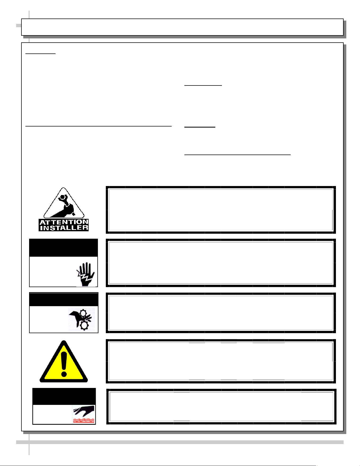
WARNING
Hazardous moving parts. Do not operate unit with covers removed.
Fan blades may be exposed when deck panel is removed.
Disconnect power before removing deck panel.
WARNING
Risk of electric shock. Disconnect power before servicing unit.
CAUTION! More than one source of electrical supply is
employed with units that have separate circuits.
Disconnect ALL ELECTRICAL SOURCES before servicing.
WARNING
ELECTRICAL
HAZARD
WARNING
KEEP
HANDS
CLEAR
COMPLIANCE
This equipment MUST be installed in compliance with
all applicable NEC, federal, state and local
electrical and plumbing codes.
OVERVIEW / TYPE / COMPLIANCE / WARNINGS / PRECAUTIONS / CORDS / WIRING - PAGE 1 of 2
WARNING
This product can expose you to chemicals, including
Urethane (Ethyl Carbamate), which are known to the state of
California to cause cancer and birth defects or other reproductive
harm. For more information go to P65Warnings.ca.gov.
WARNING
Condensate pan and overflow condensate pans are HOT!
Disconnect and allow to cool before cleaning or removing from case.
WARNING
HOT
SURFACE
PRECAUTIONS
• Following are important precautions to prevent damage
to unit or merchandise. Read carefully!
• See previous page for specifics on OVERVIEW,
CONDITION TYPE, COMPLIANCE and WARNINGS.
WIRING DIAGRAM
• Each case has its own wiring diagram folded and in its
own packet. It may be placed near ballast box, field
wiring box, raceway cover, or other related location.
REFRIGERANT DISCLOSURE STATEMENT
• This equipment is prohibited from use in California with
any refrigerants on the “List of Prohibited Substances” for
that specific end-use, in accordance with California Code
of Regulations, title 17, section 95374.
• This disclosure statement has been reviewed and
approved by Structural Concepts and Structural Concepts
attests, under penalty of perjury, that these statements
are true and accurate.
OVERVIEW / TYPE / COMPLIANCE / WARNINGS / PRECAUTIONS / CORDS / WIRING - PAGE 2 of 2
4
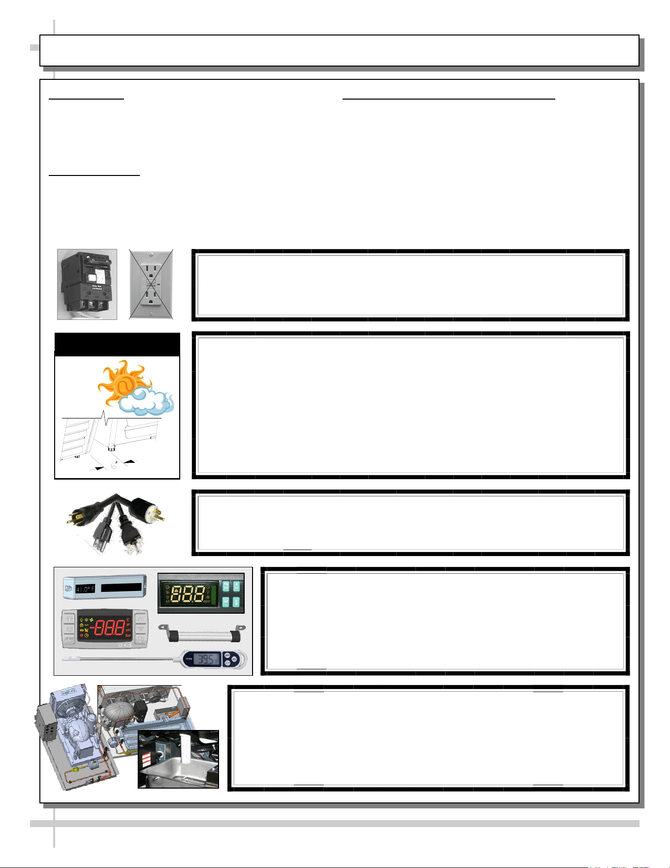
CAUTION! POWER CORD AND PLUG MAINTENANCE
Risk of electric shock. If cord or plug becomes damaged,
replace only with cord and plug of same type.
CAUTION! GFCI BREAKER REQUIREMENT
If N.E.C. (National Electric Code) or your local code
requires GFCI (Ground Fault Circuit Interrupter) protection,
you MUST use a GFCI breaker in lieu of a GFCI receptacle.
CAUTION! ADVERSE CONDITIONS / SPACING ISSUES
• Performance issues caused by adverse conditions are NOT warranted.
• To prevent damage to end panels due to condensation, apply industrial grade
silicone sealant and tightly join to opposite end panels. When not adjoining
cases, keep end panels at least 6” away from walls/structures. Rear panels
must also be kept at least 6” from walls and structures.
• Case must not be exposed to direct sunlight or any heat source.
• To maintain proper case temperature, keep case at least 15-feet from exterior
doors, overhead HVAC vents or any air curtain disruption.
• Self-contained case clearance: 6” min. air intake / 6” min. air discharge.
CAUTION
CAUTION! DO NOT RELY ON THERMOMETERS OR
THERMOSTATS FOR PRODUCT (FOOD) TEMPERATURES.
• Thermometers & thermostats reflect air temperatures ONLY.
• For ACTUAL product (food) temperatures, use a calibrated food
probe thermometers ONLY.
• For accurate readings, DO NOT use infrared food thermometers.
CAUTION! CHECK CONDENSATE PAN, ITS POSITION & PLUG!
Water on flooring can cause extensive damage!
• Before powering up case, check that condensate pan is positioned
directly under case’s condensate drain.
• Before powering up case, check that condensate pan’s electrical plug is
SECURELY connected to condensate system’s receptacle.
• If wicking material is used in condensate pan, check that it is secure.
5
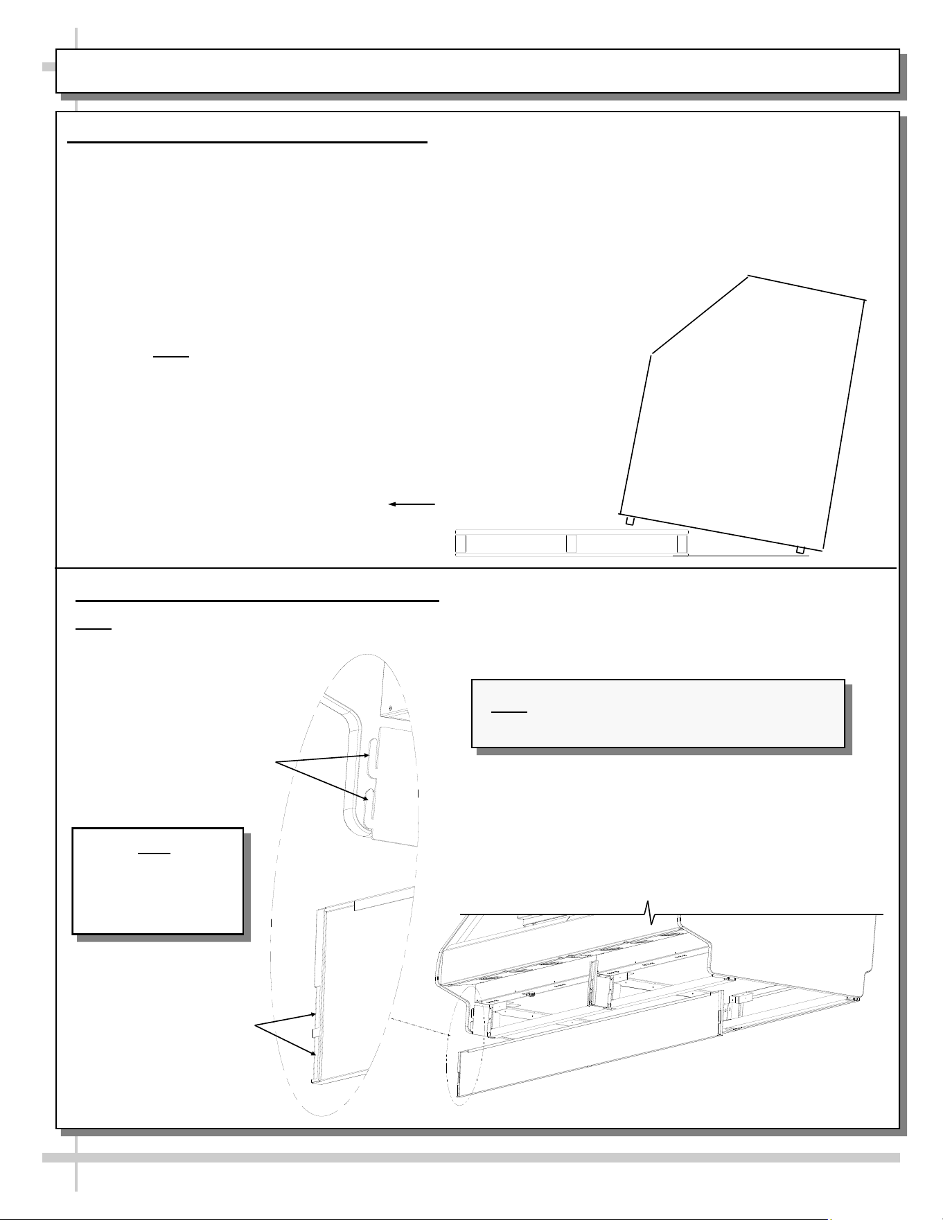
INSTALLATION: REMOVAL FROM SKID, REMOVING VERTICAL LOWER FRONT PANELS
1. Remove From Skid (Rails or Levelers)
• Remove shipping brace that may be securing case to skid.
• Support case to prevent tipping.
• Caution! Frame Support Rails (or levelers) can be damaged if case hits floor with heavy force!
• Carefully slide unit to rear of skid and tip backward off skid.
• Illustration may not reflect every feature or option of your particular case.
Note: Case can be repositioned with pallet truck
when front lower panel is removed. Blocking may
be necessary to obtain adequate height.
Slide Skid Out
2. Removing Vertical Lower Front Panels
Note: No screw removal required: Simply lift lower front panel up (off hooks) and out (away from case).
View of Front Panel (Removed & Reversed)
Hooks For Lower
Front Panel
Slots For Lower
Front Panel
Note
Lower Front Panel
Removed & Reversed
For Illustrative
Purposes Only
Note: Illustration shown may not reflect every
feature or option of your particular case.
6
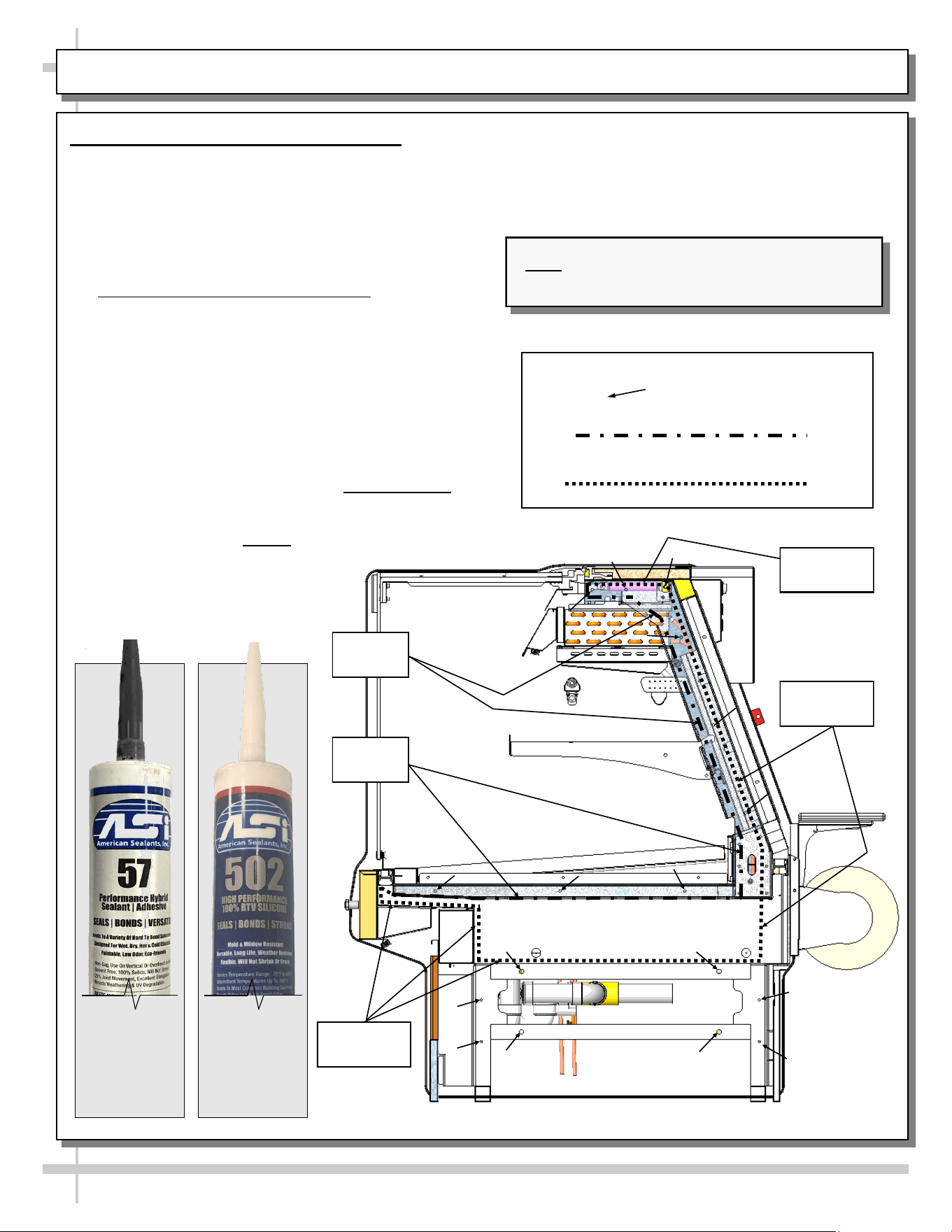
INSTALLATION, CONT’D: BOLTING AND SEALING UNITS TOGETHER
3. Bolting and Sealing Units Together
Follow these steps to assure a secure, level lineup.
A. Begin lineup leveling from highest point of floor.
B. After ‘first’ case is level, apply industrial grade
urethane on non-visible areas (at case end). Use
industrial grade silicone sealant on visible areas
(at case end). See caulk/silicone illustrations at
lower-left.
C. Form Two (2) Urethane/Sealant Lines: (Sanitation
and Refrigeration). See illustration below for
outline of urethane/sealant lines.
D. Line up ‘second’ case bolt-hole to bolt-hole to ‘first’
case.
E. Using SCC-supplied bolts (and/or screws) found in
installation packet, insert bolts in bolt hole locations
(shown below). You may need to remove decking to
access lower bolt holes.
F. Caution! Front of cases MUST be flush with each
other! After leveling, cases are to be same height.
G. Using SCC-supplied nuts & bolts, lightly tighten
each of the 5 to 8 bolts in a cross-wise pattern.
Work your way around the pattern, tightening more
firmly at each pass. Do not firmly tighten one bolt
and then start on the next!
H. After the cases are bolted together, level the
‘second’ case. Repeat this process for each case
to be adjoined.
I. After all lined-up cases are level, seal all seams
with industrial grade silicone sealant.
Approximate hole locations pointed at with
arrows ( ) for bolting units together.
Sanitation Bead
Refrigeration Bead
--- Sample Flat Glass Unit ---
Note: Illustration shown may not reflect every
feature or option of your particular case.
Sanitation
Bead
Sanitation
Bead
Refrigeration
Bead
Refrigeration
Bead
Urethane
to be
used on
non-visible
areas.
Silicone
to be
used on
visible
areas.
Refrigeration
Bead
7
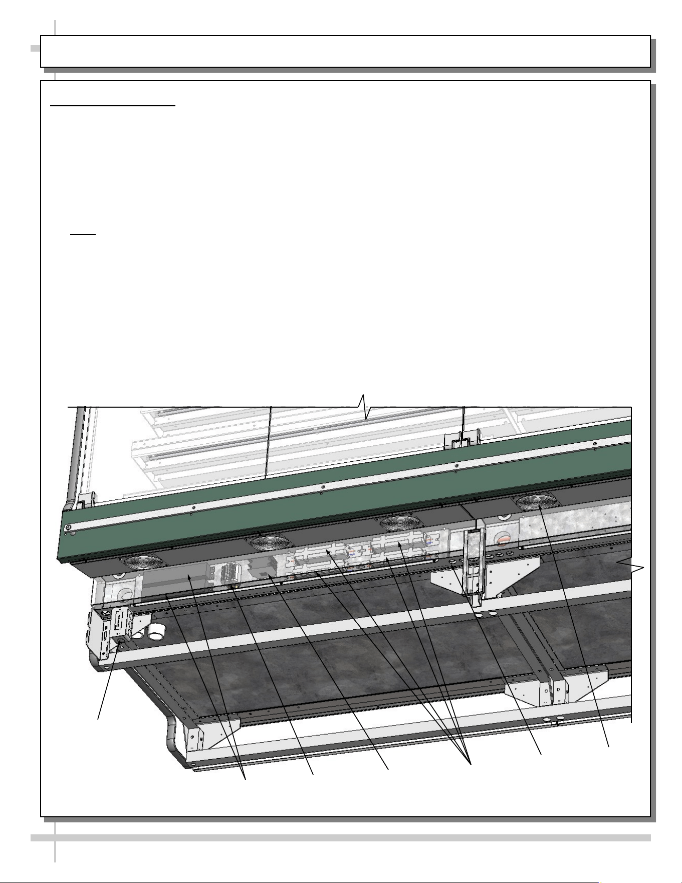
INSTALLATION, CONT’D: ELECTRICAL LAYOUT
4. Electrical Layout
Front Ballast Box or LED Driver Box (Optional)
Remove front panel. See INSTALLATION: REMOVAL FROM SKID, REMOVING VERTICAL LOWER
FRONT PANELS section in this manual for details.
• Stub-up connections are in ballast box.
• Remove ballast box / LED driver box cover.
• Knockouts are on the underside of ballast box /
LED driver box making electrical connections.
• Voltage rating is on serial label at case rear.
• Note: Wiring process must be performed by certified electrician only.
Field Access
Box
Ballasts
Terminal
Block
Contactor
LED Drivers
Axial Fan
(Typ)
Raceway
(Typ.)
8
INSTALLATION, CONT’D: FRONT FAN ACCESS
5. Front Fan Access
Front Ballast Box
• Remove screws along outer area of case.
• Remove screws along inner area of case.
• Drop Front Fan panel down.
• Repair/replace fans.
• Replace in reverse order it was removed.
• Voltage rating is on serial label at case rear.
Note: Wiring process must be performed by
certified electrician only.
Remove screws along
outer area of case
Remove screws along
inner area of case
Front Fan
Panel
Front Fan
Panel
9
INSTALLATION, CONT’D: FRAME SUPPORT RAILS / SEALING TO FLOOR
6. Cases With Frame Support Rails: Shim
• Partially disassembled illustration at right shows case with frame support rails.
• Shims will be provided with all cases that have frame support rails.
• Use shims to level case.
• Note: After case is in position, it must be sealed to floor to prevent entry or leakage of liquid or
moisture.
Frame Support Rails
Note: Illustration shown may not reflect every
feature or option of your particular case.
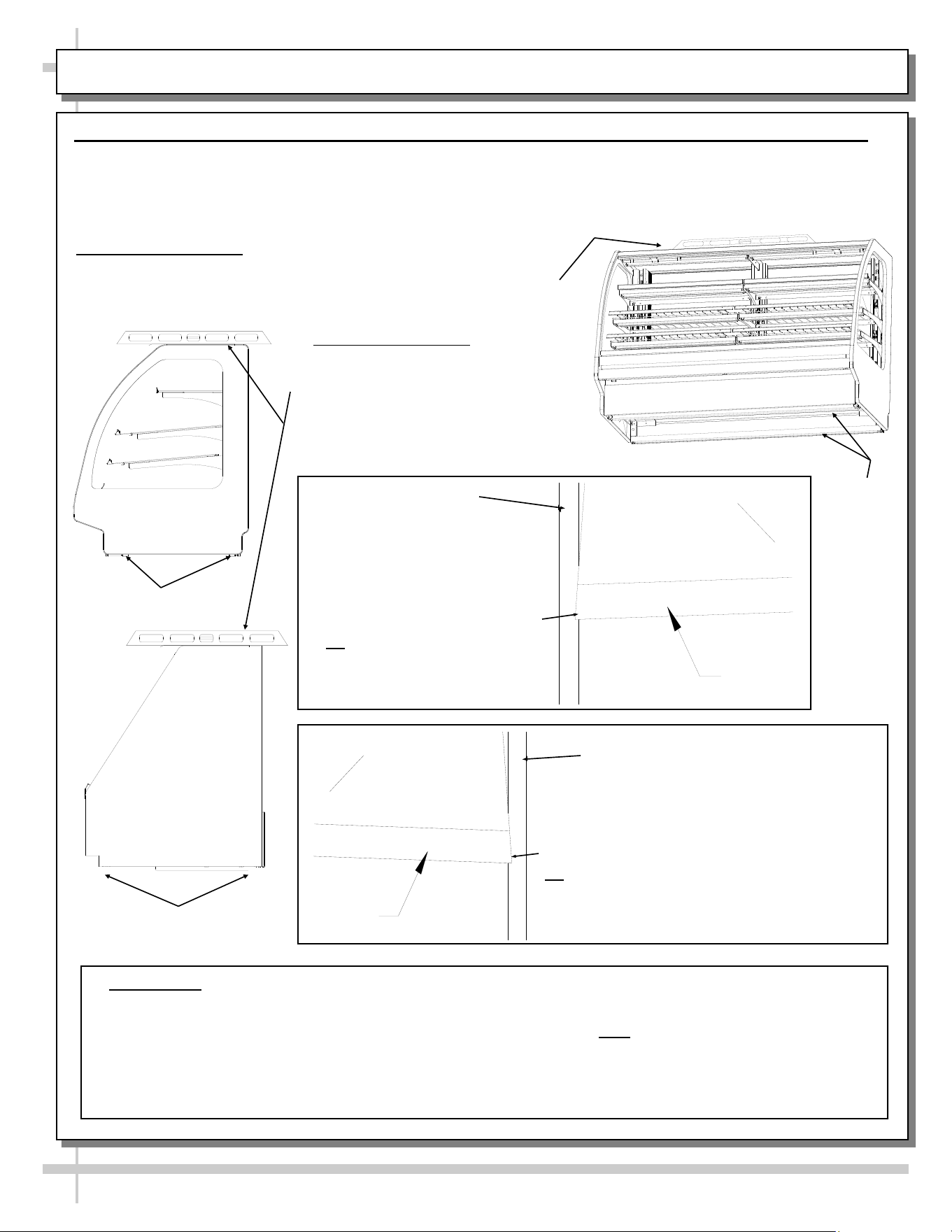
INSTALLATION, CONT’D: FRONT GLASS ALIGNMENT & ADJUSTMENT - RAILS / LEVELERS
10
Case with Curved
Front Glass
7. Front Glass Alignment & Adjustment via Rails / Levelers (For Curved / Flat Front Glass)
• Proper alignment of the front glass is important to create and maintain a seal inside the case.
• Improper alignment can cause air leaks compromising the environment inside the case and create condensation.
• Follow the five steps listed below to assure proper front glass alignment.
B. Front-to-Back Leveling:
• Place a level on top of case,
perpendicular to the front glass.
• Raise or lower either side of case by
shimming under the rails or adjusting
levelers (following steps 3 & 4 below).
• Double-check the side-to-side level.
A. Side-to-Side Leveling: Place a level on top of display case (parallel
to front glass). Level the case by inserting shims under the rails (or,
for levelers, rotating either clockwise or counter-clockwise).
Follow steps 3 and 4 below for specifics.
E. Verification:
• After inserting shims (or adjusting levelers), open and shut the front glass.
• Verify (again) that front glass is properly aligned at left-hand and right-hand side of the case.
• If not, repeat the shimming procedure (or leveler adjustment) until the front glass is properly
aligned along both sides of the case.
CURVED
FRONT
GLASS
END
PANEL
LIFT
D. If FRONT-RIGHT CORNER is too close
to end panel (or hitting it), insert shims at
the BACK RIGHT CORNER of case.
Or, for leveler system, adjust levelers at the
BACK RIGHT CORNER of case
DOWNWARD.
LIFT
END
PANEL
CURVED
FRONT
GLASS
C. If FRONT-LEFT CORNER
is too close to end panel (or
hitting it), insert shims at the
BACK LEFT CORNER of case.
Or, for leveler system, adjust
levelers at the BACK LEFT
CORNER of case DOWNWARD
END PANEL
Case with Flat
Front Glass
END PANEL
Rails
Shown
Rails or Levelers
Rails or Levelers
11
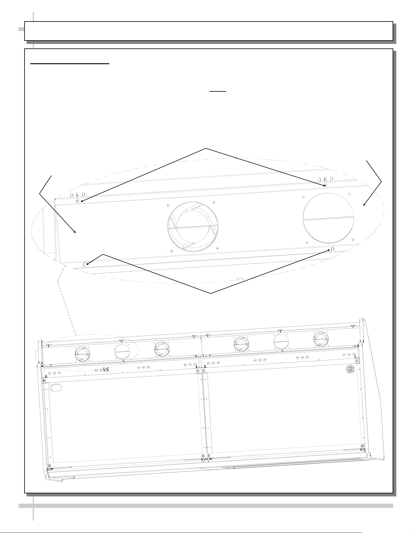
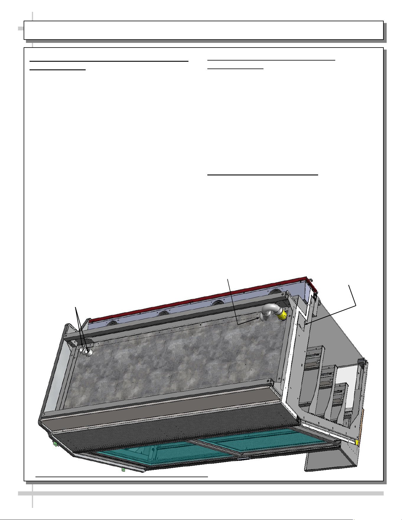
INSTALLATION, CONT’D: REFRIGERATION LINES / STUB-UPS / DRAINS / WIRING DIAGRAMS
8. Refrigeration Line Stub-Up Connections
(Remote Units)
• Remove front panel.
• Refrigerant stub-up access opening is at the
front on the left hand side of the base (see
illustration at top-right).
• Stub-up connections are accessed from inside
the case.
• Remove interior decks.
• Remove fan shroud assembly.
• Line connections are in the tub front, on the left
hand side
• Remove foam material from the entry hole
provided in the tub drain trough.
• Route refrigerant lines through access hole.
• Run case-to-case connections through
cutouts in base.
• Sweat the high and low pressure
connections.
• Fill access hole with suitable filler to insure
watertight integrity of tub.
• Illustration at top-right may not reflect every
feature or option of your particular case.
9. Refrigeration Drain Connection
(Remote Units)
• Depending upon drain access needs, either front
or rear panel may be removed to gain access to
drain stub-up.
• 1.5” male PVC stub-up connection is under the
case on the right hand side.
• Drain stub-up may be at case center in extended
length cases.
• Connect tub drain to floor drain. Maintain
1/4”-fall per foot to provide proper drainage.
• Illustration at top-right may not reflect every
feature or option of your particular case.
10. Electrical Wiring Diagram
• Each case has its own wiring diagram folded
and in its own packet.
• Wiring diagram placement may vary; it may
be placed near condenser fan cover, ballast
box, raceway cover, or other related location.
Refrigeration
Line Stub-Ups
Access
Cutout For
Case-To-Case
Adjoinment
Drain Stub-Up (may be at case
center inextended length cases)
12
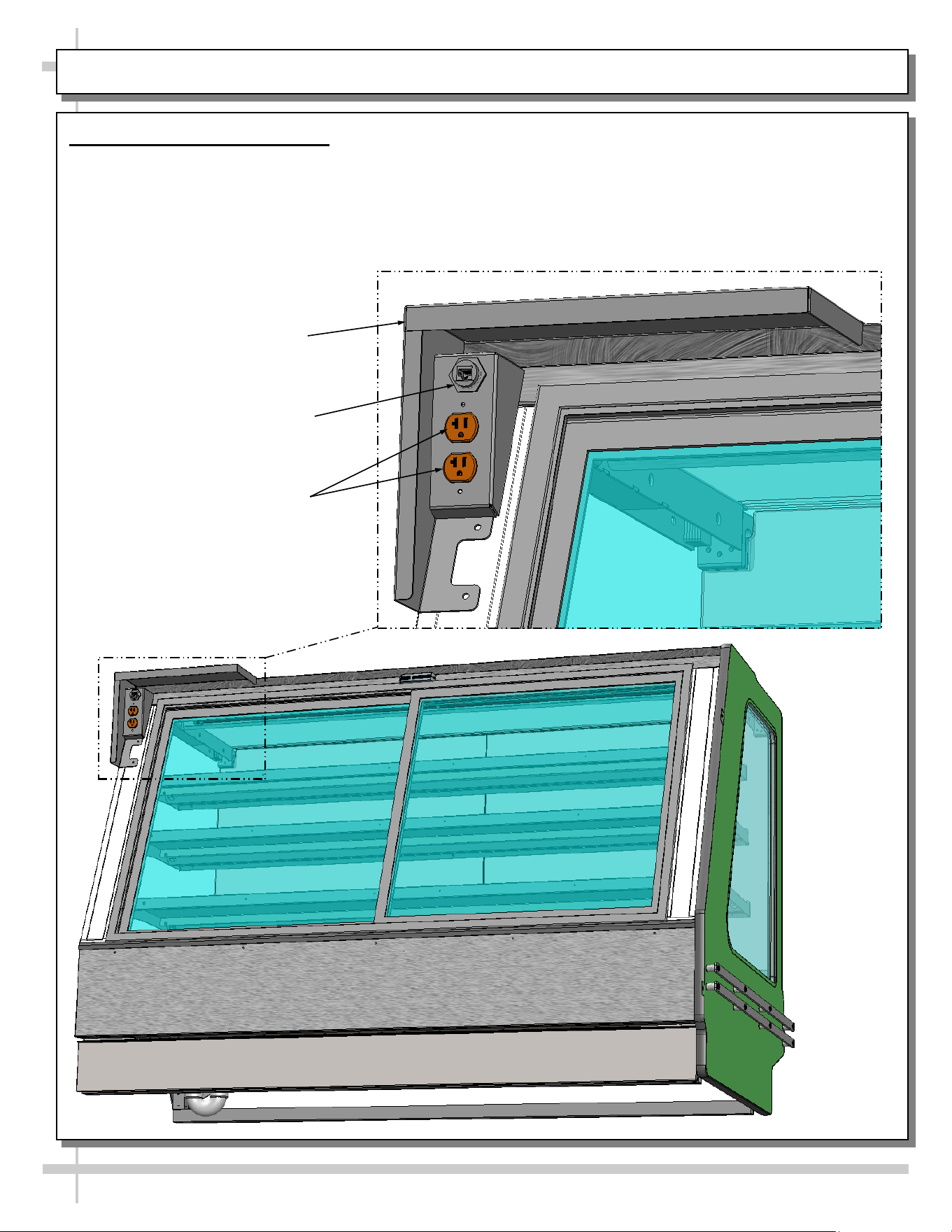
INSTALLATION, CONT’D: SCALE STAND / OUTLETS / CAT-5 RECEPTACLE
• There are three (3) scale stands and outlets.
• Only use 110V plugs that are compatible with
scale stand outlets.
11. Scale Stands and Outlets
Scale Stands and Outlets
• Scale stands and outlets are mainly found on
Model GHSAC852. However, they may also be
on other models.
Receptacles
CAT-5 Receptacle
Scale Stand
13
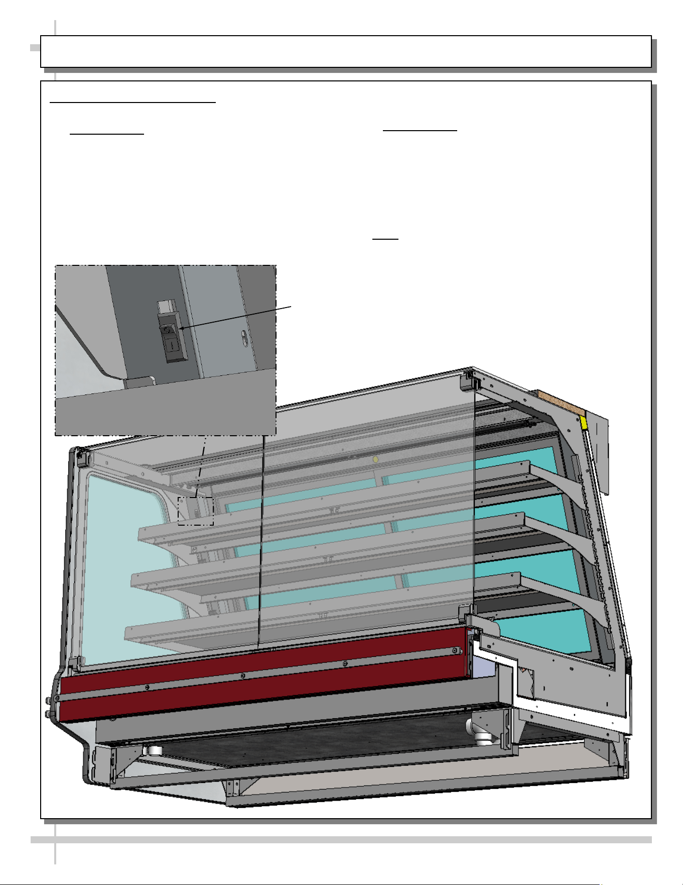
INSTALLATION, CONT’D: DISPLAY CASE START-UP
12. Display Case Start-Up
A. Case
• Remote Units: Case will power-up when properly
field wired.
• After case is powered up, open rear doors (or
front glass (see illustration below).
• If at case front, lift decking to check that coil fans
are running.
• Coil fans (and in self-contained units, compressor
motor) should turn on.
B. Lights
• Turn lights on.
> Remote Units: Switch is likely at rear plenum or
upright (as shown below).
• All lights should come on at the same time.
• Lighting is wired in series so all lights must be
plugged in or receptacles capped for case
lights to be on. See illustration at right.
• LED Lights may have single or dual rows
(depending upon model).
• Note: If lights do not come on, check that plug is
properly inserted into socket.
Light Switch
14
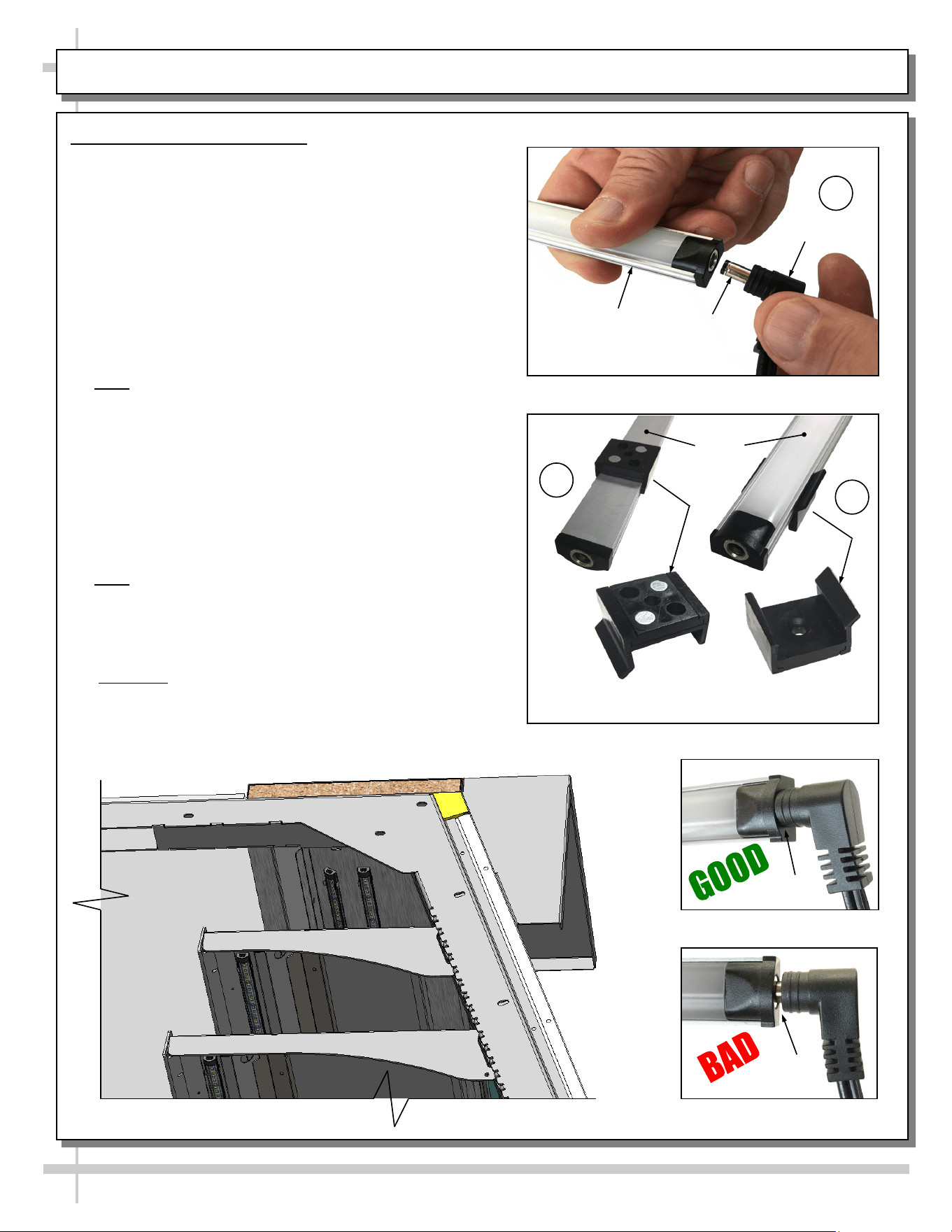
MAINTENANCE: LED LIGHT REMOVAL/REPLACEMENT, PLUG/CORD CONNECTION
1. LED Style Light Fixtures
Removal of Faulty LED Lights:
• Contact Structural Concepts’ Technical Service
Department for replacement LED lights.
• Turn off LED light switch.
• To remove faulty LED light, follow these steps:
A. Disconnect plug from LED light.
B. Using both hands, grasp LED light assembly
(with its magnetic mounting clips). Pull
downward and off its shelf (or header).
C. Remove magnetic mounting clips from LED light
by pressing against flange part of clip with
thumb.
>> Note: Mounting clips MAY be riveted to shelf or
header. In such instances, simply remove LED light from
mounting clips by pressing against flange part of clips
with thumb.
Replacement of LED lights:
• Attach magnetic mounting clips onto LED light.
• Adjust magnetic mounting clips so they are equally
spaced on LED light.
• Reattach LED light assembly to its shelf/header.
• Position properly in shelf/header.
>> Note: If mounting clips are riveted to shelf (or head-
er), attach by placing LED in base of clip and then
snapping into clip at FLANGE SIDE.
• Press plug’s barrel-shaped insert deep into LED
light.
• Important: If plug is not inserted ALL THE WAY IN
the LED light’s orifice, the light may not energize.
See “BAD” vs. “GOOD” insertion illustrations
below-right.
• Turn LED light switch back on.
Magnetic Mounting
Clip View #2
LED
Lights
B
A
Plug
Barrel
Shaped
Insert
LED
Light
C
Magnetic Mounting
Clip View #1
No Gap
Gap
15
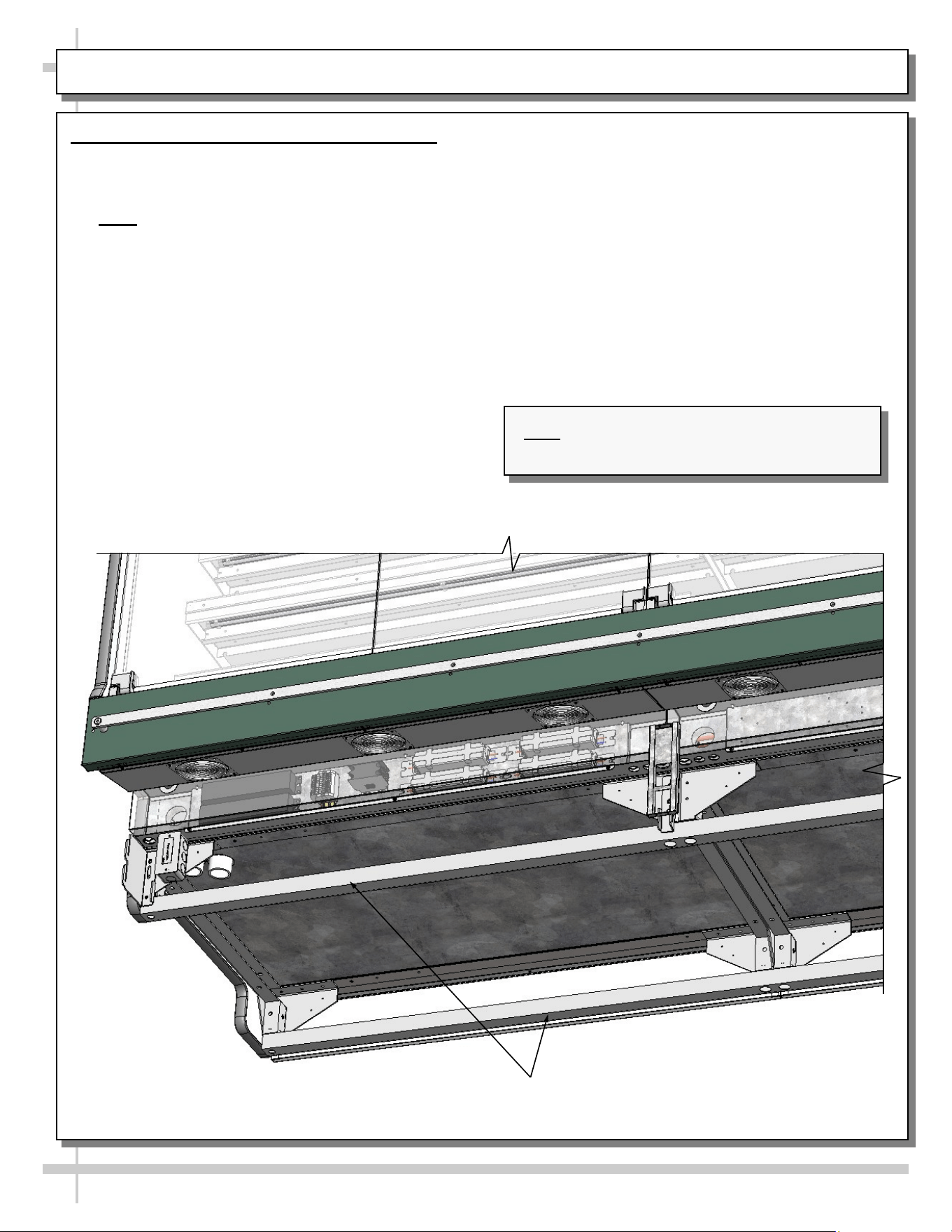
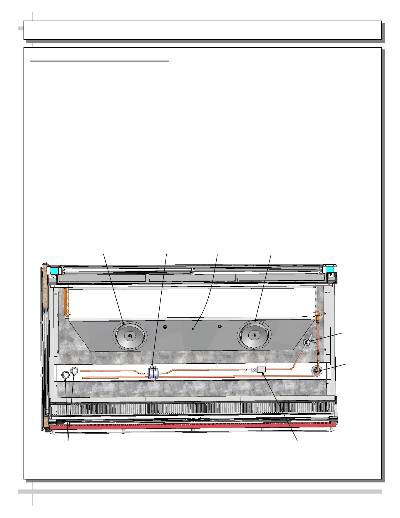
MAINTENANCE, CONT’D: DRAIN / TXV / REFRIGERATION LINES / SOLENOID / EVAPORATOR FANS
2. Drain and Expansion Valve Access
• The drain and expansion valve are both accessible from the front of the case.
• Unplug the fans (one plug per side) and remove the fastener from the access panel in the front right
(or left) corner of the unit (as shown in illustration at right).
• The drain, thermostatic expansion valve (TXV) and shut-off valve (optional, depending upon model) are
directly below the access panel.
• See illustration below for partially disassembled model depicting solenoid valve, drain, refrigeration lines,
TXV, etc.
TXV
View of Case With Decking, Rear Plenum
and End Panel Shown Removed for
Illustrative Purposes Only
Evaporator
Fan
Evap. Fan
Shroud
Filter Dryer
Solenoid
Evaporator
Fan
Evaporator
Fan
Drain
16
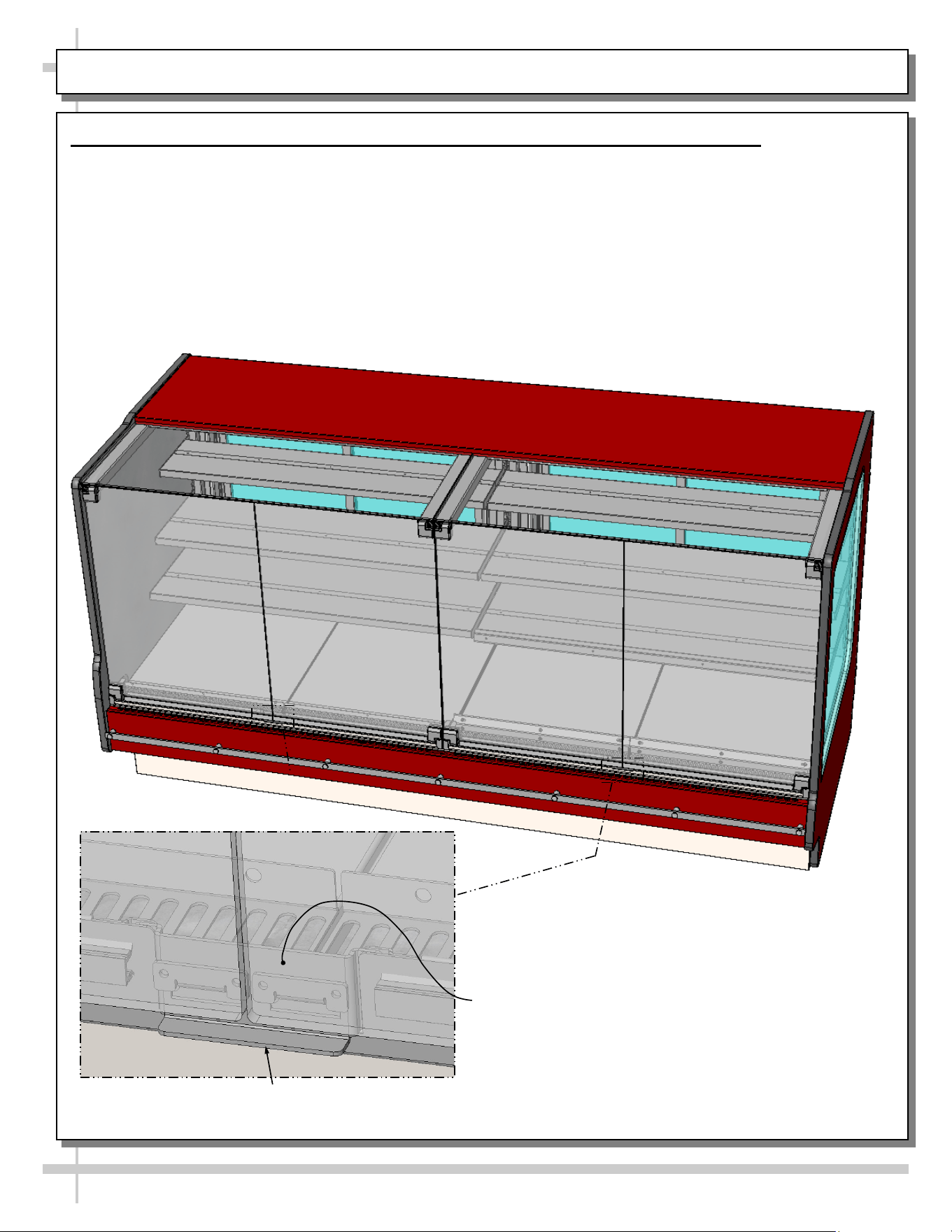
MAINTENANCE, CONT’D: REAR SLIDING DOORS / THERMOMETER
3. Rear Sliding Doors
Note: Doors are not interchangeable. There is an
inner and outer door.
• The outer door is the right hand door (from the
service side or rear of case).
• It is identified by a stop located at the lower right
hand corner to the inside of the case.
• To remove, move doors toward the center of the
case.
• Outer door must be removed first and replaced
last.
• Individually lift each door up toward the top of the
case; pivot the bottom of the door out.
• Carefully set rear sliding doors down to prevent
them from falling.
• Replace rear sliding doors in reverse order they
were removed.
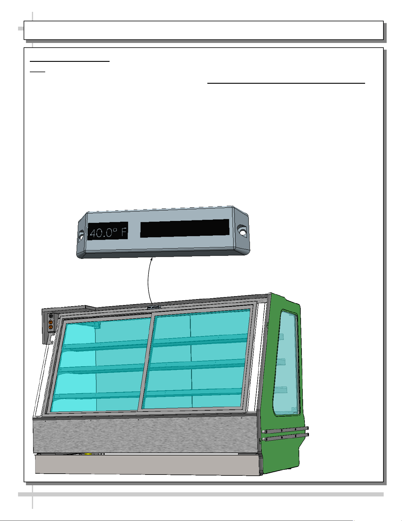
4. Thermometer (Placement and Function)
• Thermometers are found at varying locations.
Illustration below shows rear-center placement.
Yours may vary.
• Thermometers provided with equipment reflect
internal air temperature only (NOT actual food
temperature).
• Use probe thermometers to determine actual
product temperatures.
Thermometer
17
MAINTENANCE, CONT’D: HINGED FRONT DOORS WITH LOCKING MECHANISM
5. Hinged Front Doors With Locking Mechanism (Model GHSV852RLB Shown)
• Caution! Do not open doors BEYOND their hinges stopping points. Doing so can weaken or break door
hinges or glass.
• These models’ locking mechanisms prevent easy entry from customers and allows merchandiser to be
accessed from front by store personnel only.
• To allow either set of doors to be opened at side hinges, lift upward on locking mechanism, grasp
underside of glass doors and slowly open outward.
• Doors will open at side hinges. After access, doors may be slowly closed with light pressure.
• Caution! After doors have fully closed, you must press downward on locking mechanism to prevent
doors from being opened by customers.
Lift Up Here To Raise Locking Mechanism
And Allow Doors To Open
Partially Disassembled View of
Locking Mechanism (That Prevents
Front Doors From Being Opened)
18
GENERAL CLEANING (TO BE PERFORMED BY STORE PERSONNEL)
AREA FREQ. INSTRUCTIONS
Exterior Daily Front Hinged Glass Doors / Rear Sliding Glass Doors / Side Glass: Clean with
a household or commercial glass cleaner. Clean out door track with moist cloth.
Daily End Panels, Front Panel, Toe-Kick, Scale Stands, etc.: Wipe off all surfaces
with warm water and mild soap solution and non-abrasive cloth.
Weekly Wood, Laminate and Painted Surfaces: Clean with mild soap and water solution
and a soft cloth.
Interior Daily Shelves/Decking: Shelves and decking can be cleaned with a warm soap and
water solution. For stubborn stains/residue, decks can be removed and cleaned
with soap and water solution or submersed in hot, soapy water solution. Rinse
thoroughly. Dry. Return to case.
Weekly Shelving Brackets / Air Return Grilles
• Wipe off shelving brackets and air return grilles with moist cloth.
• Shelving brackets can be removed for more thorough cleaning.
• Air return grilles can be removed for more thorough cleaning.
• Decking is NOT to be removed by store personnel.
Monthly Condenser Coil: Vacuum or brush grille condenser coil at case front. Use metal
or fiber brush to remove dust and dirt that can collect on condenser coils. Be
careful not to damage the fins on the coil. See INSTALLATION section in manual
for side panel removal information.
19
TROUBLESHOOTING (TO BE PERFORMED BY STORE PERSONNEL)
CONDITION TROUBLESHOOTING
Case Not Lining Up See INSTALLATION section in this manual for instructions on properly
aligning case (alongside other cases) and shimming rails.
Water Is On The Floor Call service provider.
Fan Emits Excessive Noise Call service provider.
Case Lights Are Not
Working
Check that Light switch is in the on position.
Check that ALL of the light cords and plugs are properly connected. See
MAINTENANCE: LED LIGHT REMOVAL/REPLACEMENT, PLUG/CORD
CONNECTION section in manual.
If case lights still do not come on, call service provider.
Case is Not Holding Proper
Temperature
If a large amount of warm product was added to the case, it will take time
for the temperature to adjust. Product must be pre-chilled before placing
in case.
Check that the case is not in the sun or near a heat or air-conditioning
vent. See OVERVIEW / TECHNICAL INFORMATION / WARNINGS
section in this manual for specifics.
If case is located near front doors, temperature fluctuation can hinder
unit’s ability to maintain temperature.
Check air return grilles (area at front of decking) for obstructions. DO NOT
set product on air grilles as this will prevent proper airflow!
If case still is not holding proper temperature, call service provider.
20
GENERAL CLEANING (TO BE PERFORMED BY TRAINED SERVICE PROVIDERS ONLY)
AREA TO CLEAN FREQUENCY INSTRUCTIONS
Case Interior Monthly Evaporator Fan Shroud Area (Under Decking): Caution! Due to
rotating fans in area, turn off case and disconnect plug from
wall outlet before beginning fan shroud (and surrounding tub
area) cleaning! 1) Turn off power. 2) Remove decks from case.
3) Clean fan shroud area (and surrounding tub area) with moist
cloth.
Quarterly Tub & Drain: Caution! Due to rotating fans in area, turn off
case and disconnect plug from wall outlet before beginning
tub & drain cleaning! Vacuum tub under decks. Clean with soap
and water solution. Wipe dry with clean cloth. Keep drain free of
debris to prevent clogging.
21
CONDITION TROUBLESHOOTING
Case Not Lining
Up
See INSTALLATION section in this manual for instructions on properly aligning case
(alongside other cases) and adjusting levelers.
Water Is On The
Floor
Caution! Water on flooring can cause much damage! Until cause is determined (and
repaired), following these procedures:
• Use wet-dry vacuum (or mop & bucket) to remove standing water.
• Use ‘catch pans’ for water to drain into. Swap out regularly until case has
completely drained.
Note: See Drain, Hose and Bracket Placement Illustrations sheet in this manual for
views of different condensate systems used in display cases.
Check that the drain trap is free of debris.
Check that the drain hose is correctly positioned over condensate pan (or floor drain,
for remote units).
Check store conditions.
• To prevent condensation in NSF/ANSI Type I environments, maximum conditions
are to be 55% relative humidity / 75° Fahrenheit.
• For NSF/ANSI Type II environments, maximum conditions are to be 55% relative
humidity / 80° Fahrenheit.
• If you are unsure if your unit is classified as NSF/ANSI Type I or Type II, see tag
next to serial label on your case.
TROUBLESHOOTING (TO BE PERFORMED BY TRAINED SERVICE PROVIDERS ONLY) - PAGE 1 of 3
22
CONDITION TROUBLESHOOTING
Fan Emits Excessive
Noise
Check that the case is aligned, level and plumb.
Check evaporator fan for cleanliness.
Unplug/power off fan motors. Check motor shaft for bearing wear.
Check that fan motors are securely mounted in brackets.
Verify that fan blades are securely mounted to fan motor.
Check that nothing is preventing blade rotation.
Check that the fan shroud is properly secured.
Fans Are Not Working Check that fans are plugged in at the fan shroud.
Check for foreign material obstructing fan performance.
Check that fan blades freely rotate within fan shrouds
Check that power is going to fans
Check that fan wiring is connected on terminal blocks.
System Not Operating Check that the utility power is on.
Check that the MAIN power switch is on.
Check the circuit breaker box for tripped circuits.
TROUBLESHOOTING (TO BE PERFORMED BY TRAINED SERVICE PROVIDERS ONLY) - PAGE 2 of 3
23
CONDITION TROUBLESHOOTING
Case Lights Are Not
Working
Check that light switch is in the on position.
Check that ALL of the light cords and plugs are properly connected. See
MAINTENANCE: LED LIGHT REMOVAL/REPLACEMENT, PLUG/CORD
CONNECTION section in this manual.
Service Technicians Only: Check voltage at LED drivers. If voltage is entering but
not exiting, LED driver may be faulty.
Control Display Is
Flashing
See your case’s serial label for your model’s specified settings. See SERIAL
LABEL LOCATION & INFORMATION LISTED / TECH INFO & SERVICE for label
location, etc.
Case Is Not Holding
Temperature
If a large amount of warm product was added to the case, it will take time for the
temperature to adjust. Unit needs product to be pre-chilled.
Temperature changes during defrost mode but will return to normal. Fourth LED will
indicate defrost cycle in progress.
Check that case is not in sun or near a heat or air-conditioning vent. See
OVERVIEW AND WARNINGS section in manual for adverse conditions/spacing
issue parameters.
If case is located near outside doors, temperature fluctuation can hinder unit’s
ability to maintain temperature. See OVERVIEW AND WARNINGS section in
manual for adverse conditions/spacing issue parameters.
Check that condenser coil has been cleaned.
Check air return grilles for obstructions.
TROUBLESHOOTING (TO BE PERFORMED BY TRAINED SERVICE PROVIDERS ONLY) - PAGE 3 of 3
24
PREVENTIVE MAINTENANCE (TO BE PERFORMED BY TRAINED SERVICE PROVIDER)
PREVENTIVE
MAINTENANCE
FREQ. INSTRUCTIONS
Case Exterior Quarterly Under Case Cleaning: Once refrigeration package is clear of unit, vacuum
under case to remove dust and dirt that may collect under case.
Case Interior Quarterly Tub Area (Evaporator Coil, Drain, Fans, Brackets):
Caution! Disconnect power from the case before cleaning tub, coil,
fan, motor and drain area!
• Use vacuum to clean entire area.
• After vacuuming, clean area with warm water, clean cloth, and mild
soap solution.
• Remove any debris that may clog drain.
• Wipe down fan blades, motors and brackets with moist cloth.
WARNING! TURN OFF CASE BEFORE PERFORMING PREVENTIVE MAINTENANCE!
25
SERIAL LABEL LOCATION & INFO LISTED / TECH INFO & SERVICE / REFRIGERATED CASES ONLY
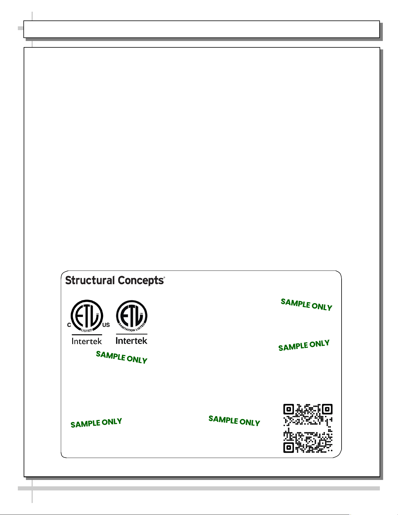
--- Sample Serial Label For Refrigerated Cases ---
MODEL NRS3648RXV-SAMPLE
SERIAL NO. 12345X30DZ098765
888 E. Porter Rd - Muskegon, MI 49441
3048256
Conforms to UL Std. 471
Conforms to NSF/ANSI Stds. 2 & 7
CERTIFIED TO CAN/CSA
STD C22.2 NO 120
ELECTRICAL RATING
REFRIGERANT
DESIGN PRESSURE
MINIMUM CIRCUIT AMPACITY
MAXIMUM OVERCURRENT
120/1/60 16 A
R513A AMOUNT 50 OZ
HIGH 186 LOW 88
20A
20A
Super Heat Temp 6-8 °F FOR PARTS AND SERVICE
Defrost 6 defrosts per day, 45 °F CALL 1-800-433-9490
Serial Label Location & Information Listed /
Technical Information & Service
• Serial labels are affixed at a wide range of places
(on the header, near thermostat, at case rear,
behind panels/toe-kicks, on electrical boxes, etc.).
• Serial labels contain electrical, temperature and
refrigeration information, as well as regulatory
standards to which the case conforms.
• Sample serial label shown below.
• A wide range of models are shown
• For additional technical information and service, see
the TECHNICAL SERVICE page in this manual for
instructions on contacting Structural Concepts’
Technical Service Department.
Reveal
Harmony
Fusion
Impulse
Addenda
Blend
Grocerant
Oasis
Sample QR Code
SCAN FOR PRODUCT LITERATURE
STRUCTURAL CONCEPTS TECHNICAL SERVICE CONTACT INFORMATION & LIMITED WARRANTY
26
TECH SERVICE/WARRANTY CONTACT INFO:
1 (800) 433-9490 / EXTENSION 1
DAYS/HOURS AVAILABLE:
MONDAY - FRIDAY (CLOSED HOLIDAYS)
8:00 A.M. to 8:00 P.M. EST
YOU MUST HAVE THE FOLLOWING INFO AVAILABLE
BEFORE CONTACTING STRUCTURAL CONCEPTS:
SERIAL NO. / MODEL NO. / STORE NO. / STORE
ADDRESS / DETAILS (PHOTOS, LEAK LOCATIONS,
DAMAGE, STORE’S AMBIENT CONDITIONS, ETC.)
To Access The Limited Warranty To Your
Case, Follow These Instructions:
> If Viewing This Document on Smart Phone,
Tablet or Computer, Select/Click On The QR
Code at Right.
> If Viewing This Document In Print (Hard
Copy), Scan The QR Code at Right With Your
Smart Phone or Tablet.