OPERATOR'S MANUAL
MODEL #100166
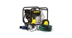
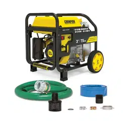
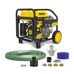
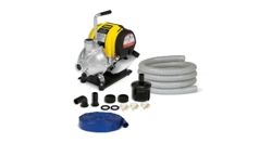
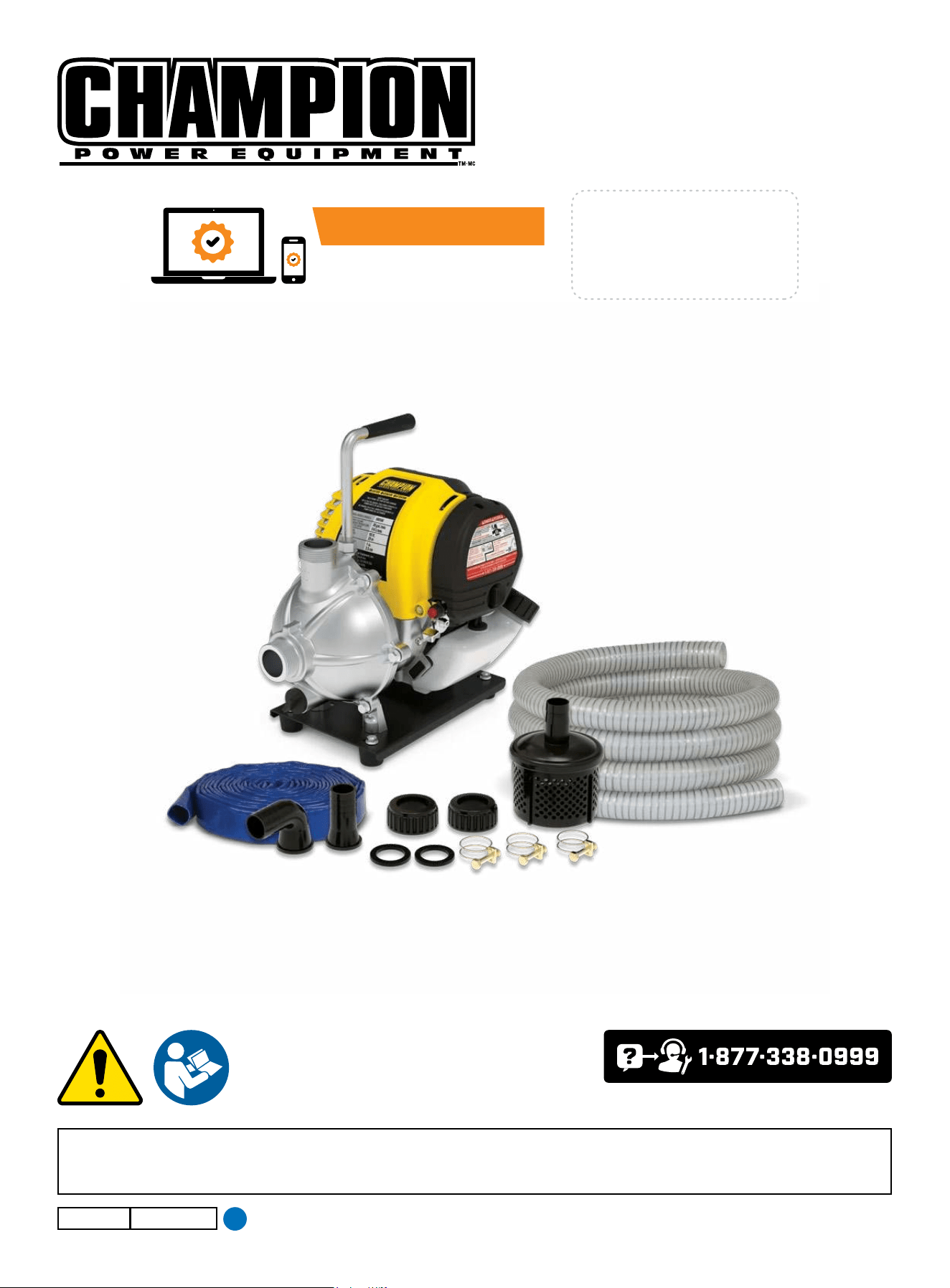
1 IN. (2.5 CM) WATER PUMP WITH HOSE KIT
Champion Power Equipment, Inc.
or visit championpowerequipment.com
SAVE THESE INSTRUCTIONS. This manual contains important safety precautions which should be read and understood before operating the product. Failure to do
so could result in serious injury. This manual should remain with the product.
Specifications, descriptions and illustrations in this manual are as accurate as known at the time of publication, but are subject to change without notice.
3713-M-OP REV 20250623
EN
ACTIVATE YOUR WARRANTY
by registering your product:
championpowerequipment.com
SERIAL NO.

100166 - 1 IN. (2.5 CM) WATER PUMP WITH HOSE KIT
TABLE OF CONTENTS
2
TABLE OF CONTENTS
Introduction
................................................... 3
Safety Definitions
..........................................3
Important Safety Instructions
.......................4
Fuel Safety ........................................................ 5
Safety and Dataplate Labels ...................................... 7
Controls and Features ...................................8
Water pump ....................................................... 8
Parts Included ..................................................... 9
Tools Included ..................................................... 9
Assembly ..................................................... 10
Unpacking ........................................................ 10
Install the Handle ................................................. 10
Add Engine Oil .................................................... 10
Add Fuel .......................................................... 11
Operation ..................................................... 12
Water Pump Location ............................................ 12
Priming the Pump ................................................ 13
Connecting the Inlet Hose ....................................... 13
Connecting the Outlet Hose ...................................... 14
Starting the Engine ............................................... 15
Stopping the Engine .............................................. 15
Maintenance ................................................ 16
Cleaning the Water pump ........................................ 16
Changing the Engine Oil ......................................... 16
Cleaning and Adjusting the Spark Plug(s) ....................... 16
Cleaning the Air Filter ............................................ 17
Adjusting the Governor ........................................... 17
Maintenance Schedule ........................................... 17
Storage ........................................................ 18
Specifications
.............................................. 19
Water pump Specifications ...................................... 19
Engine Specifications ............................................ 19
Oil Specifications ................................................. 19
Fuel Specifications ............................................... 19
Temperature Specifications ...................................... 19
Troubleshooting ........................................... 20

100166 - 1 IN. (2.5 CM) WATER PUMP WITH HOSE KIT
INTRODUCTION
3
SAFETY DEFINITIONS
The purpose of safety symbols is to attract your attention to
possible dangers. The safety symbols, and their explanations,
deserve your careful attention and understanding. The safety
warnings do not by themselves eliminate any danger. The
instructions or warnings they give are not substitutes for proper
accident prevention measures.
DANGER
DANGER indicates a hazardous situation which, if not avoided,
will result in death or serious injury.
WARNING
WARNING indicates a hazardous situation which, if not
avoided, could result in death or serious injury.
CAUTION
CAUTION indicates a hazardous situation which, if not avoided,
could result in minor or moderate injury.
NOTICE
NOTICE indicates information considered important, but not
hazard-related (e.g., messages relating to property damage).
INTRODUCTION
Congratulations on your purchase of a Champion Power Equipment
(CPE) product. CPE designs, builds, and supports all of our
products to strict specifications and guidelines. With proper
product knowledge, safe use, and regular maintenance, this
product should bring years of satisfying service.
Every effort has been made to ensure the accuracy and
completeness of the information in this manual at the time of
publication, and we reserve the right to change, alter and/or
improve the product and this document at any time without prior
notice.
CPE highly values how our products are designed, manufactured,
operated, and serviced as well as providing safety to the operator
and those around the water pump. Therefore, it is IMPORTANT to
review this product manual and other product materials thoroughly
and be fully aware and knowledgeable of the assembly, operation,
dangers and maintenance of the product before use. Fully
familiarize yourself, and make sure others who plan on operating
the product fully familiarize themselves too, with the proper safety
and operation procedures before each use. Please always exercise
common sense and always err on the side of caution when
operating the product to ensure no accident, property damage,
or injury occurs. We want you to continue to use and be satisfied
with your CPE product for years to come.
When contacting CPE about parts and/or service, you will need to
supply the complete model and serial numbers of your product.
Transcribe the information found on your product’s nameplate
label to the table below
CPE TECHNICAL SUPPORT TEAM
1-877-338-0999
MODEL NUMBER
100166
SERIAL NUMBER
DATE OF PURCHASE
PURCHASE LOCATION
100166 - 1 IN. (2.5 CM) WATER PUMP WITH HOSE KIT
IMPORTANT SAFETY INSTRUCTIONS
4
IMPORTANT SAFETY INSTRUCTIONS
WARNING
Cancer and Reproductive Harm – www.P65Warnings.ca.gov
DANGER
Water pump engine exhaust contains carbon monoxide, a
colorless, odorless, poisonous gas. Breathing carbon monoxide
will cause nausea, dizziness, fainting or death. If you start to
feel dizzy or weak, get to fresh air immediately.
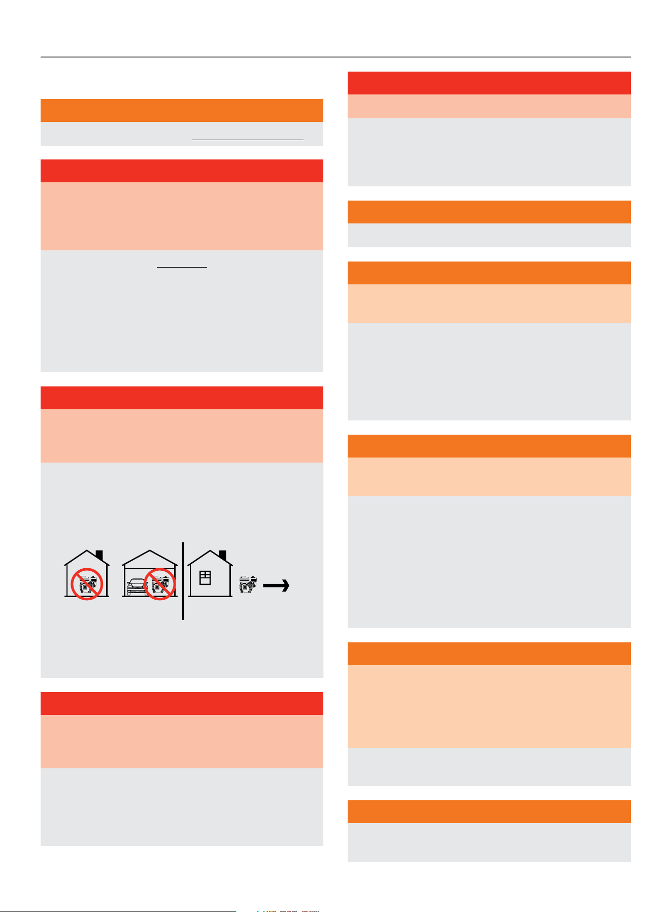
OPERATE WATER PUMP OUTDOORS ONLY IN A WELL
VENTILATED AREA AND POINT EXHAUST AWAY.
DO NOT operate the water pump inside any building, including
garages, basements, crawlspaces and sheds, enclosure or
compartment.
DO NOT allow exhaust fumes to enter a confined area through
windows, doors, vents or other openings.
DANGER
Using an engine indoors CAN KILL YOU IN MINUTES. Water
pump exhaust contains carbon monoxide. This is a poison you
cannot see or smell.
NEVER use inside a home or garage, EVEN IF doors and
windows are open.
ONLY use OUTSIDE and far away from windows, doors,
and vents.
Install battery-operated carbon monoxide alarms or plug-in
carbon monoxide alarms with battery back-up according to the
manufacturer’s instructions.
DANGER
Rotating parts can entangle hands, feet, hair, clothing and/or
accessories. Traumatic amputation or severe laceration can
result.
Keep hands and feet away from rotating parts.
Tie up long hair and remove jewelry.
DO NOT wear loose-fitting clothing, dangling drawstrings or
items that could become caught.
DANGER
The water pump develops powerful force.
DO NOT move the water pump when it is in use. DO NOT use
hoses or connectors that are worn, damaged or frayed. DO
NOT allow children or unqualified persons to operate or service
the water pump. DO NOT open top plug or drain plug.
WARNING
DO NOT immerse this unit in water.
WARNING
Spark from removed spark plug wire can result in fire or
electrical shock.
When servicing the water pump:
Disconnect the spark plug wire and place it where it cannot
contact the plug or any other metal object.
DO NOT check for spark with the plug removed.
Use only approved spark plug testers.
WARNING
Running engines produce heat. Severe burns can occur on
contact. Combustible material can catch fire on contact.
DO NOT touch hot surfaces.
Avoid contact with hot exhaust gases.
Allow equipment to cool before touching.
Maintain at least 3 ft. (91.4 cm) of clearance on all sides to
ensure adequate cooling.
Maintain at least 5 ft. (1.5 m) of clearance from combustible
materials.
WARNING
Rapid retraction of the recoil cord will pull hand and arm
towards the engine faster than you can let go. Broken bones,
fractures, bruises or sprains could result. Unintentional
startup can result in entanglement, traumatic amputation or
laceration.
When starting engine, pull the recoil cord slowly until
resistance is felt and then pull rapidly to avoid kickback.
WARNING
DO NOT pump salt, sludge, sewer, sea, or any other type of
water containing solid material.

100166 - 1 IN. (2.5 CM) WATER PUMP WITH HOSE KIT
IMPORTANT SAFETY INSTRUCTIONS
5
WARNING
Water pumped through this unit shall not be used as drinking
water.
CAUTION
Pumping solids through the pump, impeller or hoses is not
recommended.
CAUTION
Exceeding the water pump’s specification for maximum head
can damage the water pump and/or hose kits connected to it.
DO NOT modify the water pump in any way.
DO NOT attempt to exceed the rated flow. Attempting to
increase the rated flow may damage the unit and/or shorten
its life.
CAUTION
Improper treatment or use of the water pump can damage it,
shorten its life or void the warranty.
Use the water pump only for intended uses.
Operate only on level surfaces.
DO NOT expose water pump to excessive moisture, dust,
or dirt.
DO NOT allow any material to block the cooling slots.
DO NOT use the water pump if:
– Equipment sparks, smokes or emits flames
– Equipment vibrates excessively
Fuel Safety
DANGER
GASOLINE AND GASOLINE VAPORS ARE HIGHLY
FLAMMABLE AND EXPLOSIVE.
Fire or explosion can cause severe burns or death.
Gasoline and gasoline vapors:
– Gasoline is highly flammable and explosive.
– Gasoline can cause a fire or explosion if ignited.
– Gasoline is a liquid fuel but it’s vapors can ignite.
– Gasoline is a skin irritant and needs to be cleaned up
immediately if spilled on skin or clothes.
– Gasoline has a distinctive odor, this will help detect potential
leaks quickly.
– Gasoline expands or contracts with ambient temperatures.
Never fill the gasoline tank to full capacity, as gasoline needs
room to expand when temperatures rise.
– In the case of any petroleum gasoline fire, flames should never
be extinguished unless the fuel supply valve can be turned
OFF. By not doing so, if a fire is extinguished and the supply
of fuel is not turned OFF, an explosion hazard could be created.
When adding or removing gasoline:
DO NOT light or smoke cigarettes.
Turn the water pump off and let cool for at least two minutes
before removing the gasoline cap. Always loosen the cap slowly to
relieve pressure in the tank.
Only fill or drain gasoline outdoors in a well-ventilated area.
DO NOT pump gasoline directly into the water pump at the gas
station. Always use an approved container to transfer the fuel to
the water pump.
DO NOT overfill the gasoline tank.
Always keep gasoline away from sparks, open flames, pilot lights,
heat and other sources of ignition.
When starting the water pump:
DO NOT attempt to start a damaged water pump.
Always check that the gasoline cap, air filter, spark plug, fuel lines
and exhaust system are properly in place.
Always allow spilled gasoline to evaporate fully before attempting
to start the engine.
Always be certain that the water pump is resting firmly on level
ground.
When operating the water pump:
DO NOT move or tip the water pump during operation.

100166 - 1 IN. (2.5 CM) WATER PUMP WITH HOSE KIT
IMPORTANT SAFETY INSTRUCTIONS
6
When transporting or servicing the water pump:
Always check that the fuel valve is in the OFF position and the
gasoline tank is empty.
Disconnect the spark plug wire.
When storing the water pump:
Store away from sparks, open flames, pilot lights, heat and other
sources of ignition.
Do not store water pump or gasoline near furnaces, water heaters,
or any other appliances that produce heat or have automatic
ignitions.
DANGER
NEVER place a gasoline container, gasoline tank, or any
combustible material in the path of the exhaust stream during
operation of the engine.
WARNING
Never use a gasoline container, gasoline tank, or any other fuel
item that is broken, cut, torn or damaged.
100166 - 1 IN. (2.5 CM) WATER PUMP WITH HOSE KIT
IMPORTANT SAFETY INSTRUCTIONS
7
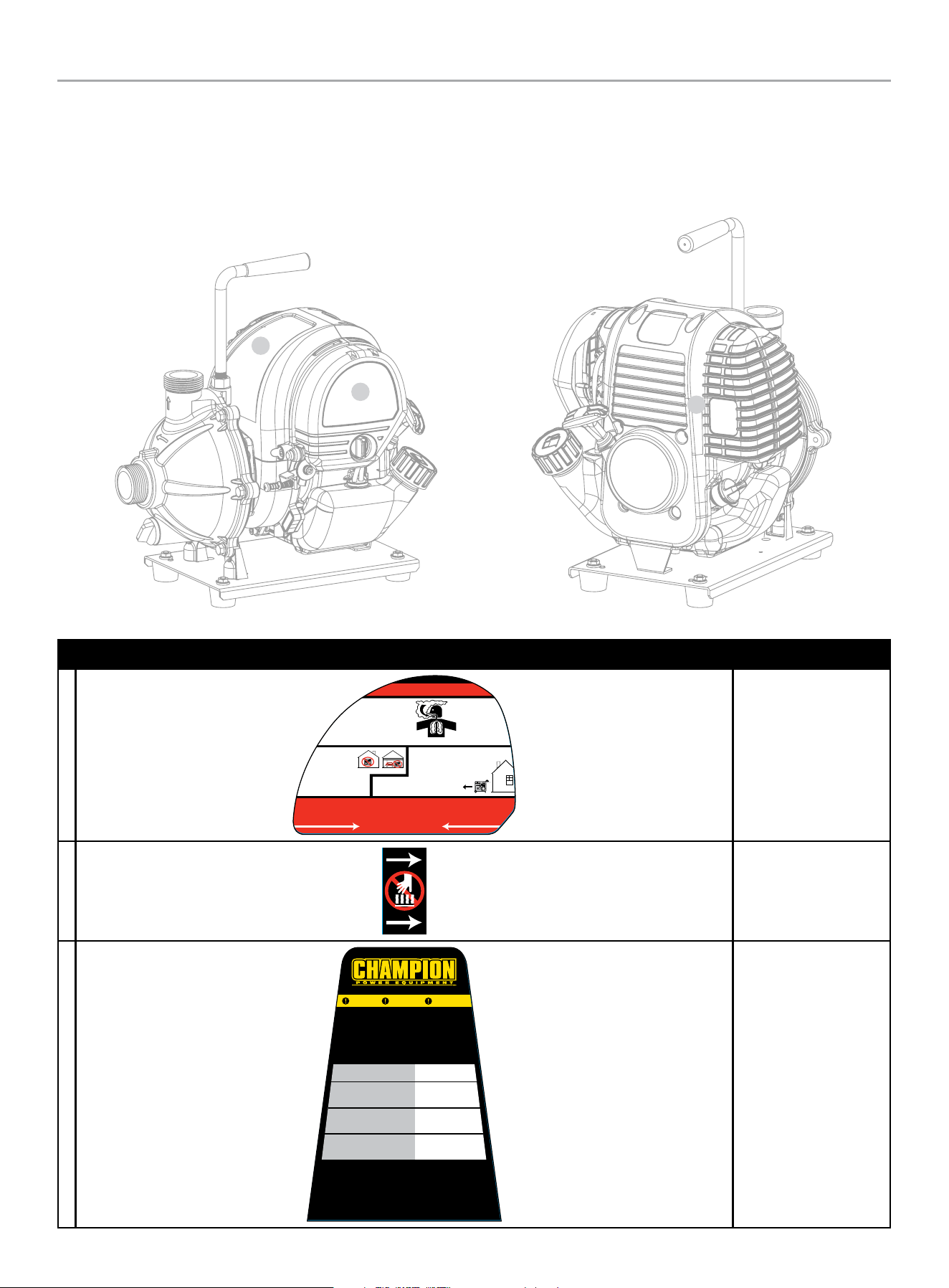
Safety and Dataplate Labels
These labels warn you of potential hazards that can cause serious injury. Read them carefully.
If a label comes off or becomes hard to read, contact Technical Support Team for possible replacement.
LABEL DESCRIPTION
A
CALL CUSTOMER SE RVICE / LLA ME A NUESTRO EQUIPO DEAT ENCIÓN AL CLIENTE / COMMUNIQUER AVEC NOTRE ÉQ UIPE DE SERVICE À LA CLIEN TELE
DO NOT RETURN THIS PRODUCT TO THE STORE! / ¡NO DEVUELVA ESTE PRODUCTO A LA TIENDA!
1-877-338-0999
ÉVITER DE RETOURNER CE PRODUIT AU MAGASIN!
El usa de este producto en
interiores PUEDE
CAU SARL E LA MUE RTE EN
MINUTOS. El escape
contiene monóxido de
carbono. Éste es un veneno
que no se puede ver ni oler.
PELIGRO DE MONÓXIDO
DE CARBONO
CARBON MONOXIDE HAZARD
Using this product indoors CAN KILL
YOU IN MINUT ES. Exhaust contains
carbon monoxide. This is a poison you
cannot see or smell.
Utiliser de cet produit à l’intérieur PEUT VOU S TUER
EN QUELQU ES MINUTES. L’écha ppe me nt du produit contient
du monoxyde de carbone. Il s’agit d’un poison que vois ne pouvez ni voir ni senti.
RISQUE DE MONOXYDE DE CARBONE
NUCNA lo use dentro
del hogar ni el garaje,
INCLUSO si las puer tas y
ventanas están abiertas
Úselo SÓLO a la INTEMPERIE lejos
de ventanas, puertas y orificios de
ventilación.
NEVER use inside a home or garage,
EV EN IF doors and windows are open.
ONLY use OUTSIDE and far away from windows,
doors, and vents.
Ne l’utilisez JAMAIS dans la maison ou le
garage MÊME SI les portes et les fenêtres
sont ouvertes.
Utilisez-le UNIQUEMENT À L'EXTÉRIEUR, loins
des fenêtres, portes et trappes de ventilation
DANGER PELIGRO
Safety Symbols/
CO Danger
B
Hot Surface
C
DON’T RUN DRY.
FULLY PRIME THE PUMP BEFORE RUNNING.
NE TOURNEZ PAS À SEC. AMORCER PLEINEMENT LA
POMPE AVANT DE L’ACTIONNER.
MODEL/MODELO/MODÈLE 100166
DELIVERY VOLUME
VOLUMEN DE PRODUCCIÓN
VOLUME DE SORTIE
30 gal./min.
114 L/min.
TOTAL HEAD
ALTURA TOTAL
Tête totale
95 ft.
29 m
CONNECTION
CONEXION
CONNEXION
1 in.
2,5 cm
Champion Power Equipment, Inc.
6370 S Pioneer Way, Unit 101
Las Vegas, NV 89113, USA
1-877-338-0999
www.championpowerequipment.com
MADE IN CHINA / HECHO EN CHINA / FABRIQUÉ EN CHINE
ATTENTION
CAUTION
ATENCIÓN
NO LA USE SIN LÍQUIDO. CEBE COMPLETAMENTE LA
BOMBA ANTES DE HACERLA FUNCIONAR.
Dataplate
A
C
B
100166 - 1 IN. (2.5 CM) WATER PUMP WITH HOSE KIT
CONTROLS AND FEATURES
8
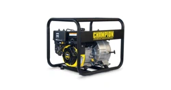
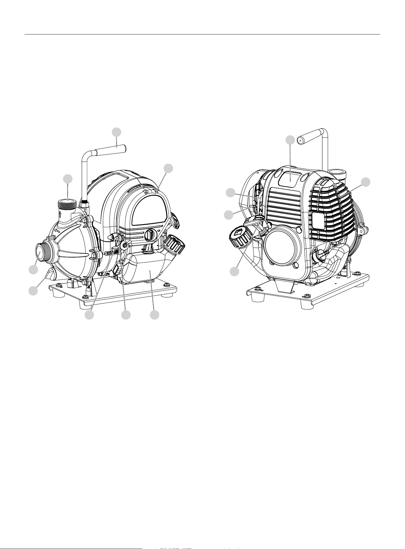
CONTROLS AND FEATURES
Read this operator’s manual before operating your water pump. Familiarize yourself with the location and function of the controls and
features. Save this manual for future reference.
Water pump
1. Drain Plug
2. 1 in. (2.5 cm) Inlet – Used to connect the suction hose
adapter converts to 1 in. (2.5 cm) inlet without adapter:
– Thread Designation G1-1/4 in. (31.75 mm)
– Nominal Size 1-1/4 in. (31.75 mm)
– Thread Form Type BSPP
– Pitch 2.3 mm
3. 1 in. (2.5 cm) Outlet – Used to connect the discharge hose:
– Thread Designation G1-1/4 in. (31.75 mm)
– Nominal Size 1-1/4 in. (31.75 mm)
– Thread Form Type BSPP
– Pitch 2.3 mm
4. Handle
5. Air Filter – Protects the engine by filtering dust and debris
from the air intake.
6. Fuel Tank – 0.145 gal. (550 mL)
7. Throttle Lever – Used to adjust engine speed.
8. Off Button – Press to stop the unit.
9. Recoil Starter – Used to start the engine.
10. Priming Button – Used to prime fuel for starting.
11. Choke lever – Used to start the engine.
12. Spark Plug and Connector Wire
13. Muffler
1
2
3
4
12
5
7 8 6
9
11
10
13
100166 - 1 IN. (2.5 CM) WATER PUMP WITH HOSE KIT
CONTROLS AND FEATURES
9
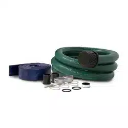
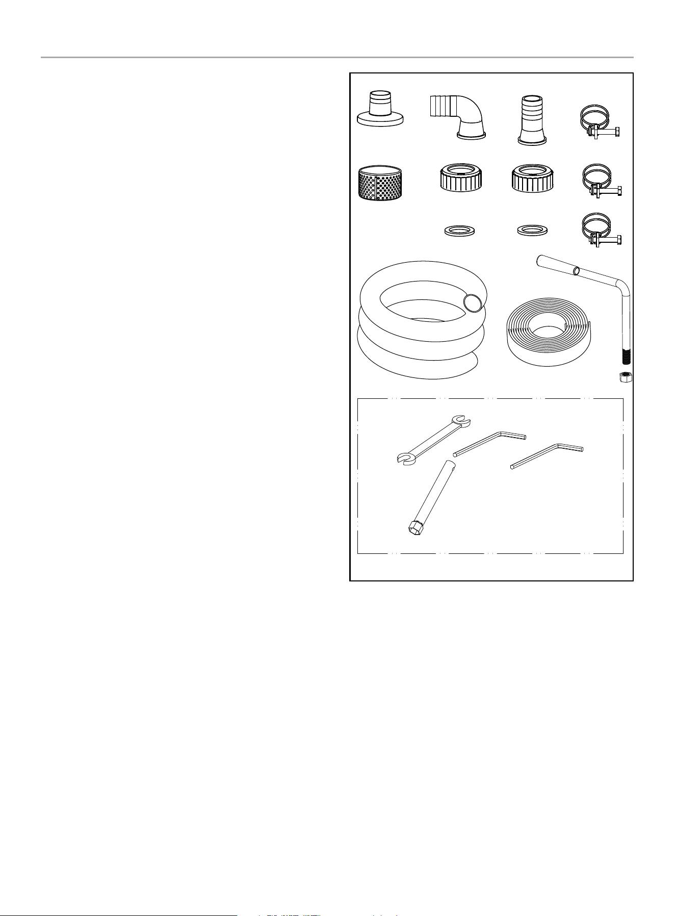
Parts Included
Accessories
Hose Kit
16.4 ft. x 1 in. (5 meter x 25mm) Intake Hose
....................1
26.2 ft. x 1 in. (8 meter x 25mm) Discharge Hose ................ 1
Hose Connector G1-1/4 in. (31.75 mm) BSPP to
1 in. (2.5 cm) Straight Adapter with rubber gasket ...............1
Hose Connector G1-1/4 in. (31.75 mm) BSPP to
1 in. (2.5 cm) 90° Adapter with rubber gasket....................1
Intake Filter Screen ................................................1
Hose Clamps .......................................................3
Assembly Parts
Handle ..............................................................1
Nut, M12x1.25 (for handle) ........................................1
Tools Included
Tool Kit ..............................................................1
100166 - 1 IN. (2.5 CM) WATER PUMP WITH HOSE KIT
ASSEMBLY
10
ASSEMBLY
Your water pump requires some assembly. This unit ships from our
factory without oil. It must be properly serviced with fuel and oil
before operation.
If you have any questions regarding the assembly of your water
pump, call our Technical Support Team at 1-877-338-0999.
Please have your serial number and model number available.
Unpacking
1. Set the shipping carton on a solid, flat surface.
2. Remove everything from the carton except the water pump.
3. Carefully cut each corner of the box from top to bottom. Fold
each side flat on the ground to provide a surface area to work
with the water pump.
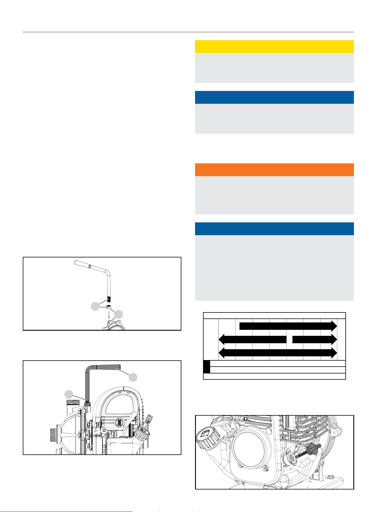
Install the Handle
1. Hand thread the M12 x 1.25 nut onto the handle base, up to a
point where it naturally stops. (A)
2. DO NOT try to thread the nut after that stop point with any
wrench, pilers, or other device.
3. Hand thread the handle/nut combo into the threaded hole on
the pump side cover top. (B)
A
B
4. Once securely tightened the handle should face away from
the outlet and towards the engine. (C)
D
C
CAUTION
Hand tighten the nut and handle only. Any excess force, with
tools or otherwise, may strip or break the threads on the
handle or side cover hole.
NOTICE
There will be some threading left on the handle that will stick out
of the nut after installation is secured. This is normal and should
be left unthreaded. (D)
Add Engine Oil
WARNING
DO NOT attempt to crank or start the engine before it has been
properly filled with the recommended type and amount of oil.
Damage to the water pump as a result of failing to follow these
instructions will void your warranty.
NOTICE
The recommended oil type for typical use is 10W-30
automotive oil. However, using the listed conventional oils
shown in the “Recommended Engine Oil Type” chart may be
used for typical use including the first 5 hours of the break-in
run time period of the engine.
If running water pump in extreme temperatures, refer to the
“Recommended Engine Oil Type” chart.
-20 0 20 40 60
Ambient temperature
Recommended Engine Oil Type
80 100 120
-28.9
°F
°C
-17.8 -6.7 4.4 15.6 26.7 37.8 48.9
10W-30
5W-30 Full Synthetic
10W-405W-30
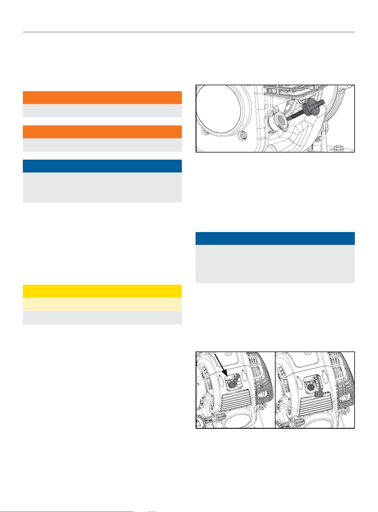
1. Place the water pump on a flat, level surface.
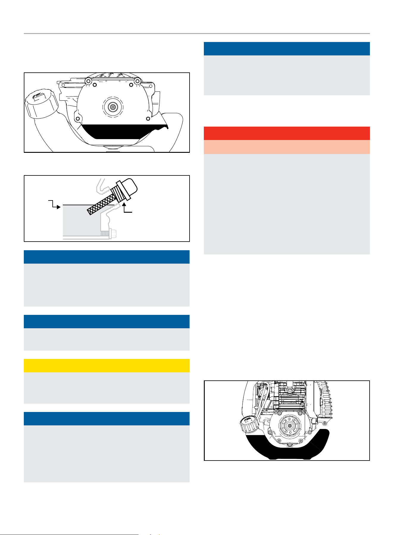
2. Remove oil fill cap/dipstick to add oil.
100166 - 1 IN. (2.5 CM) WATER PUMP WITH HOSE KIT
ASSEMBLY
11
3. Using a funnel, add up to 2.4 fl. oz. (70 ml) of oil (not
included) and replace oil fill cap/dipstick. It is recommended
to only fill to the base of the oil fill hole. DO NOT OVERFILL.
4. Check engine oil level at every use and add as needed.
MAX
OIL DIP STICK
NOTICE
Once oil has been added, a visual check should show oil about
1-2 threads from running out of the fill hole.
When using the dipstick to check oil level, DO NOT screw in
the dipstick while checking.
NOTICE
Check oil level often during the break-in period. Refer to the
Maintenance section for recommended service intervals.
CAUTION
This engine is NOT equipped with a low oil shut-off and will
NOT stop when the oil level in the crankcase falls below the
threshold level.
NOTICE
The first 5 hours of run time are the break-in period for the
unit. During the break in period stay at or below 50% of the
running watt rating and vary the load occasionally to allow
stator windings to heat and cool. Adjusting the load will also
cause engine speed to vary slightly and help seat piston rings.
After the 5 hour break-in period, change the oil.
NOTICE
Synthetic oil may be used after the 5 hour initial break-in
period. Using synthetic oil does not decrease the recommended
oil change interval. Full synthetic 5W-30 oil will aid in starting
in cold ambient < 41º F (5º C) temperatures.
Add Fuel
DANGER
Gasoline vapors are highly flammable and extremely explosive.
DO NOT light or smoke cigarettes. Fire or explosion can cause
severe burns or death.
Only fill or drain fuel outdoors in a well-ventilated area. DO
NOT pump gasoline directly into the water pump. Use an
approved container to transfer the fuel to the water pump.
Never use a gasoline container, gasoline tank, or any other fuel
item that is broken, cut, torn or damaged.
DO NOT overfill the gasoline tank. Always keep fuel away from
sparks, open flames, pilot lights, heat and other sources of
ignition.
Use clean, fresh, regular unleaded gasoline with a minimum
octane rating of 87 and an ethanol content of 10% or less by
volume. ybc
DO NOT mix oil with gasoline.
1. Remove the gasoline cap.
2. Slowly add gasoline to the tank. DO NOT OVERFILL. Gasoline
can expand after filling. A minimum of ¼ in. (6.4 mm) of
space left in the tank is required for gasoline expansion,
although more than ¼ in. (6.4 mm) is recommended. Gasoline
can be forced out of the tank as a result of expansion if
overfilled, and can affect the stable running condition of the
water pump.
3. Screw on the gasoline cap and wipe away any spilled fuel.
100166 - 1 IN. (2.5 CM) WATER PUMP WITH HOSE KIT
OPERATION
12
CAUTION
Use unleaded gasoline with a minimum octane rating of 87
and an ethanol content of 10% or less by volume.
DO NOT light cigarettes or smoke when filling the tank.
DO NOT mix oil and gasoline.
DO NOT overfill the tank. Fill tank to approximately ¼ in.
(6.4 mm) below the top of the tank to allow for gasoline
expansion.
DO NOT pump gasoline directly into the water pump at the
pump. Use an approved fuel container to transfer the gasoline
to the water pump.
DO NOT fill tank indoors.
DO NOT fill tank when the engine is running or hot.
WARNING
Pouring gasoline too fast through the fuel screen may result
in gasoline splashing over the water pump and operator while
filling.
NOTICE
The water pump engine works well with 10% or less ethanol
blended gasoline. When using ethanol-gasoline blends there
are some issues worth noting:
– Ethanol-gasoline blends can absorb more water than
gasoline alone.
– These ethanol blends can eventually separate, leaving
water or a watery goo in the tank, fuel valve and
carburetor. The compromised gasoline can be drawn into
the carburetor and cause damage to the engine and/or
create potential hazards.
– If a fuel stabilizer is used, confirm that it is formulated to
work with ethanol-gasoline blends.
– Any damages or hazards caused by using ethanol blended
gasoline higher than 10% by volume, improperly stored
gasoline, and/or improperly formulated stabilizers, are not
covered by manufacturer’s warranty.
It is advisable to always shut off the gasoline supply and
run the engine to starvation after each use. See Storage
instructions for extended non-use.
OPERATION
Water Pump Location
WARNING
Place the water pump in a well ventilated area. NEVER place
the water pump near vents or intakes where exhaust fumes
could be drawn into occupied or confined spaces. Carefully
consider wind and air currents when positioning water pump.
Water pumps should always be operated on a flat, level
surface at all times (even when not in operation).
Water pumps must have a minimum of 5 feet (1.5 m) of
clearance from all combustible material.
Water pumps must also have a minimum of 3 feet (91.4 cm)
of air flow clearance on all sides to allow for adequate
performance cooling, maintenance and servicing.
Place the pump on a level surface free from any obstructions
or potential hazards. The pump should be placed close to the
water level to ensure maximum pump performance.
Always allow water pumps to properly cool before transport or
for storage purposes.
Failure to follow proper safety precautions may result in
personal injury, damage to the water pump and void the
manufacturer’s warranty.
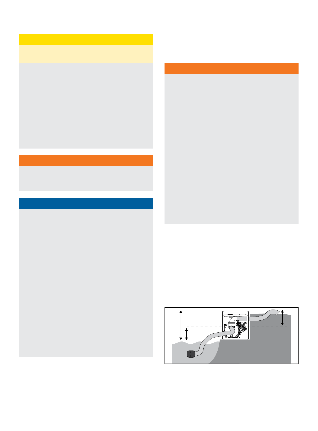
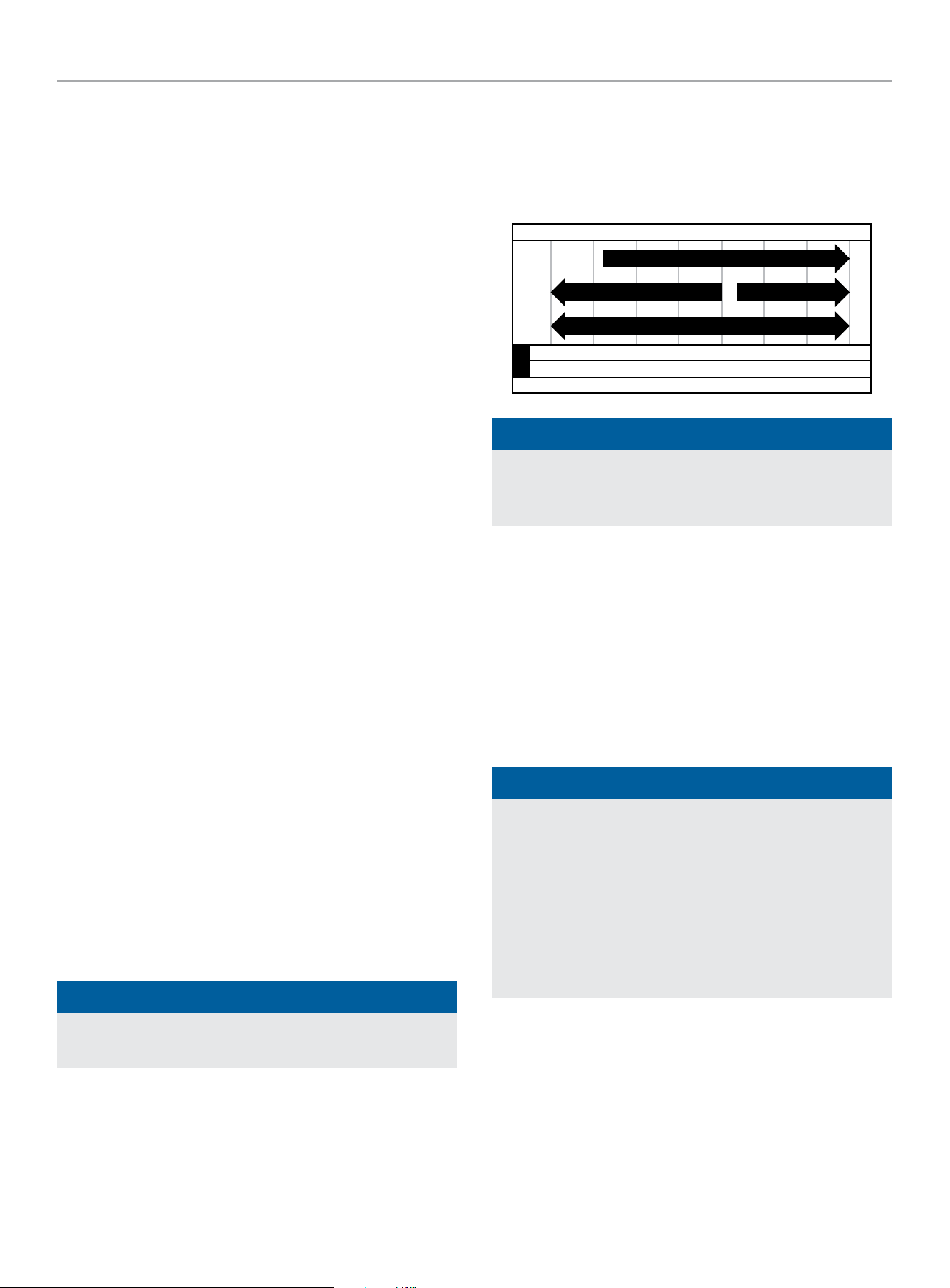
Pump output will be affected by the type, length, and size of the
suction and discharge hoses. The pumping height, also known as
the total head, is the distance from the water level to the point of
discharge. As this distance increases, pump output decreases.
The discharge capacity is greater than the suction capacity.
Therefore, it is important that the suction head is less than the
discharge head.
The time required to draw water from the source to the pump
(self-priming time) can be decreased by minimizing the suction
head.
TOTAL HEAD
DISCHARGE HEAD
SUCTION HEAD
100166 - 1 IN. (2.5 CM) WATER PUMP WITH HOSE KIT
OPERATION
13
Priming the Pump
WARNING
DO NOT run the pump dry.
Running the pump dry can destroy the pump seals and will
void the warranty. If the pump was running while dry, stop
the engine and allow it to cool thoroughly before filling the
chamber with water.
Pour water into the outlet located on top of the pump housing.
(A) Make sure to fill the pump body to the very top of the outlet
with water. Connect the outlet hose to the outlet. (See section
Connecting the Outlet Hose) Make sure hose connection is secure.
As the engine starts up, this will start the draw of liquid into the
pump. Located within the pump assembly is the one-way valve. As
you prime the pump housing this one-way flap valve shuts off the
opening to the suction hose. The priming process is only required
when the pump housing is not full of water.
A
B
NOTICE
Ensure the drain plug is secure before pump priming and
operation. (B) If not secure the pump will not hold water and
prime correctly.
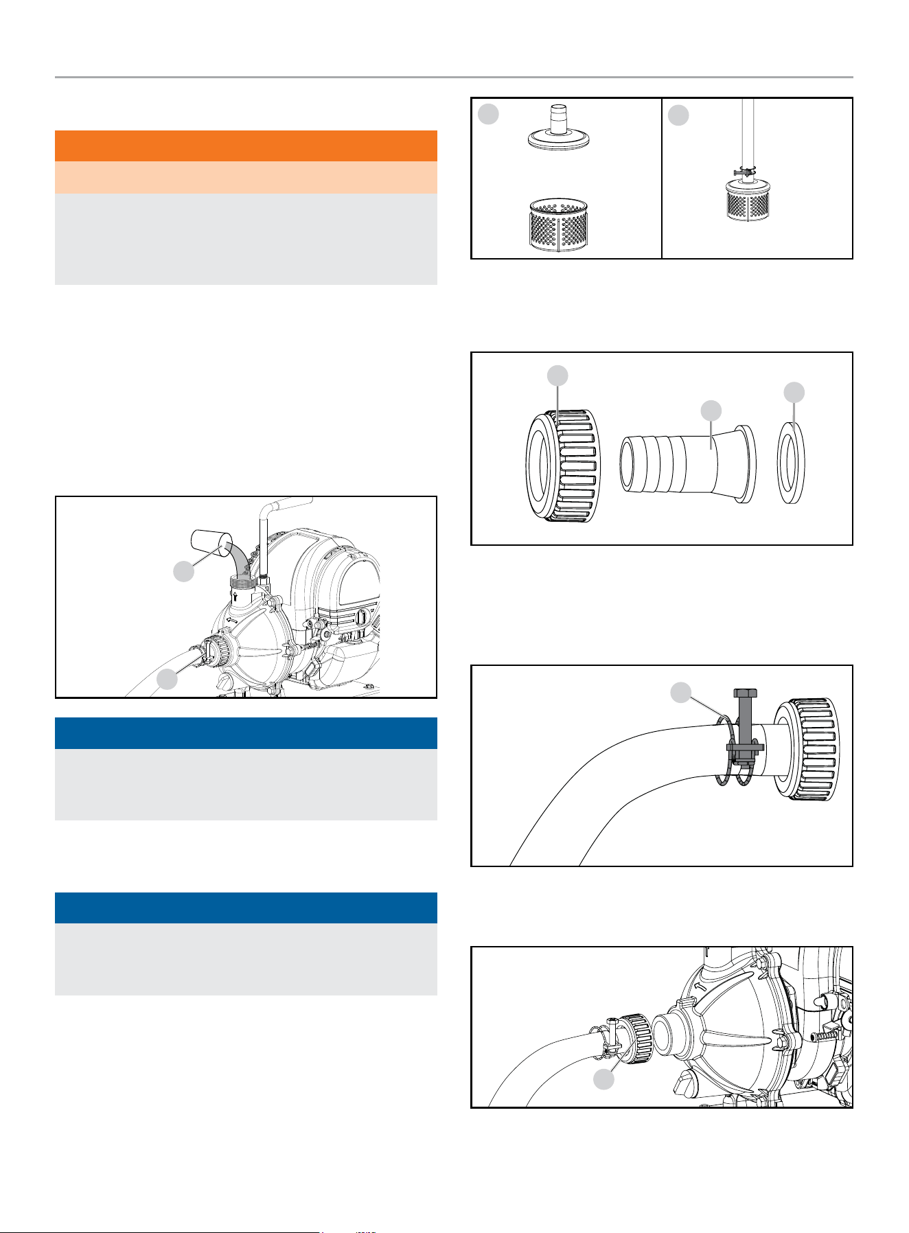
Connecting the Inlet Hose
NOTICE
Both the intake and outlet ports are 1 in. (2.5 cm). Please
insure the connectors to the suction and discharge hose are
1 in. (2.5 cm) threaded.
1. Attach the water filter shield to the water filter. (A)
2. Connect them to the intake hose with a hose clamp. (B)
3. Tighten the screw on the hose clamp to secure. Do not
overtighten.
A
B
4. Slide the pipe joint (C) over the straight outlet joint (D) and
then place the rubber gasket (E) into the base of the pipe
joint.
C
D
E
5. Connect the intake hose to the straight outlet joint with a
hose clamp. (F)
6. Tighten the screw on the hose clamp to secure. Do not
overtighten.
F
7. Connect the straight outlet joint to the pump. (G)
8. Hand tighten the joint to the pump. Do not over tighten.
G
100166 - 1 IN. (2.5 CM) WATER PUMP WITH HOSE KIT
OPERATION
14
NOTICE
The once connected to the pump, there may be some
threading left after hand tightening. This is normal. DO NOT
overtighten the pipe joint with any wrench, tool, or otherwise.
NOTICE
Telfon tape or other sealers are not needed for a water tight
connection. The rubber gasket should help to make the
connection more water tight.
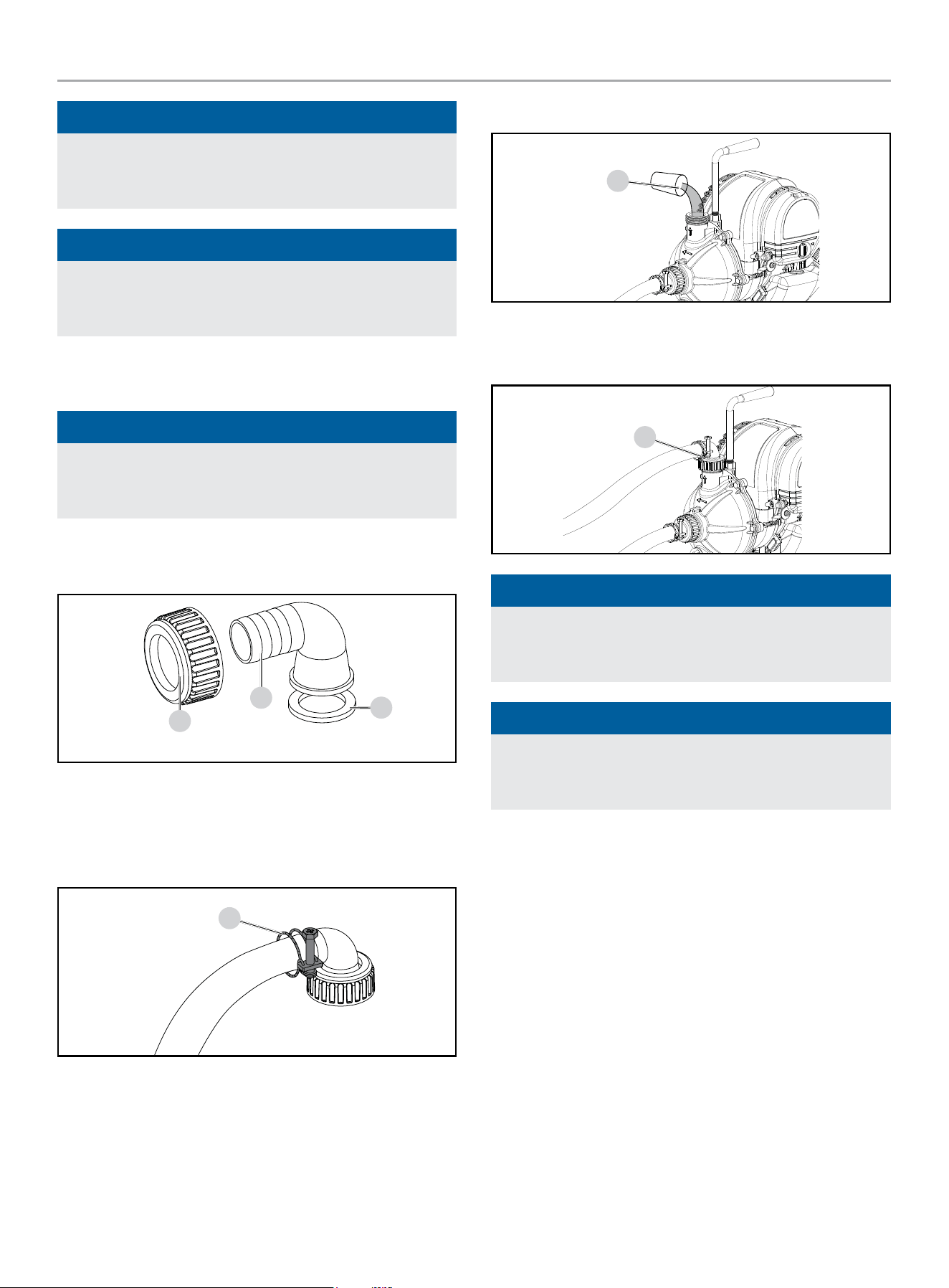
Connecting the Outlet Hose
NOTICE
Both the intake and outlet ports are 1 in. (2.5 cm). Please
insure the connectors to the suction and discharge hose are
1 in. (2.5 cm) threaded.
1. Slide the pipe joint (A) over the 90º outlet joint (B) and then
place the rubber gasket (C) into the base of the pipe joint.
A
B
C
2. Connect the outlet hose to the 90º outlet joint with a hose
clamp. (D)
3. Tighten the screw on the hose clamp to secure. Do not
overtighten.
D
4. Prime the pump. (E) See priming the pump section
E
5. Connect the 90º outlet joint to the pump. (F)
6. Hand tighten the joint to the pump. Do not over tighten.
F
NOTICE
The once connected to the pump, there may be some
threading left after hand tightening. This is normal. DO NOT
overtighten the pipe joint with any wrench, tool, or otherwise.
NOTICE
Telfon tape or other sealers are not needed for a water tight
connection. The rubber gasket should help to make the
connection more water tight.
100166 - 1 IN. (2.5 CM) WATER PUMP WITH HOSE KIT
OPERATION
15
Starting the Engine
WARNING
Before attempting to start the engine, the oil level must be
checked and engine oil added if needed.
1. Make certain the water pump is on a flat, level surface.
2. Check engine oil level. Add oil if needed. (see add engine oil
section)
3. Check fuel level. Add fuel if needed. (see add fuel section)
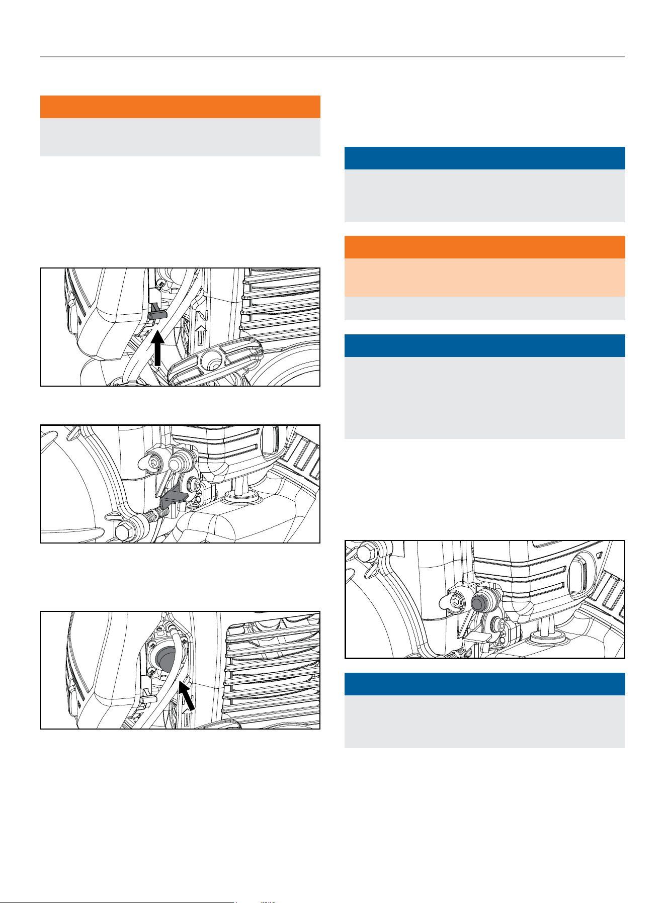
4. Move the choke lever to the “CHOKE” position.
5. Move the throttle level to the idle position.
6. Push and release the primer bulb 5 times to prime the
carburetor. You should see the bulb start to fill up with fuel
and fuel traveling through the fuel line.
7. Pull the starter cord slowly until resistance is felt and then
pull rapidly.
8. As engine warms up, move the choke lever to “RUN”.
9. Move the throttle lever to the desired RPM position.
NOTICE
Pump performance can be adjusted using the throttle. To
decrease pump output, slide the throttle down. To increase it,
slide the throttle up.
WARNING
DO NOT remove the drain plug while the water pump is on and
running
Loss of pressure and suction will occur. Injury may also occur.
NOTICE
Keep choke lever in “CHOKE” position for 2 pulls of the recoil
starter. After 2 pulls, move choke lever to the “RUN” position
for up to the next 3 pulls of the recoil starter. Too much choke
leads to spark plug fouling/engine flooding due to the lack of
incoming air. This will cause the engine not to start.
Stopping the Engine
There is a stop engine button located next to the air filter cover,
above the throttle level. Simply press the button and the unit
should turn off.
NOTICE
If the engine will not be used for a period of two (2) weeks or
longer, please see the Storage section for proper engine and
fuel storage.
100166 - 1 IN. (2.5 CM) WATER PUMP WITH HOSE KIT
MAINTENANCE
16
MAINTENANCE
Make certain that the water pump is kept clean and stored
properly. Only operate the unit on a flat, level surface in a clean,
dry operating environment. DO NOT expose the unit to extreme
conditions, excessive dust, dirt, moisture or corrosive vapors.
WARNING
Never operate a damaged or defective water pump.
WARNING
Improper maintenance will void your warranty.
NOTICE
For Emission control devices and systems, read and
understand your responsibilities for service as stated in the
Emission Control Warranty Statement of this manual.
The owner/operator is responsible for all periodic maintenance.
Complete all scheduled maintenance in a timely manner.
Correct any issue before operating the water pump.
For service or parts assistance, contact our
Technical Support Team at 1-877-338-0999.
Cleaning the Water pump
CAUTION
DO NOT spray water pump directly with water.
Water may cause unsuspected damage.
1. Use a damp cloth to clean exterior surfaces of the water
pump.
2. Use a soft bristle brush to remove dirt and oil.
3. Use an air compressor (25 PSI) to clear dirt and debris from
the water pump.
4. Inspect all air vents and cooling slots to ensure that they are
clean and unobstructed.
To prevent accidental starting, remove and ground the spark plug
wire before performing any service.
Changing the Engine Oil
Change oil when the engine is warm. Refer to the oil specification
to select the proper grade for your operating environment.
1. Remove oil fill cap/dipstick to drain and add oil.
2. Tip the pump on its side to drain all oil into an approved
container.
3. Add oil according to Add Engine Oil in Assembly section.
DO NOT OVERFILL. Oil not included for routine maintenance.
4. Replace the oil fill cap/dipstick.
5. Dispose of used oil at an approved waste management
facility.
NOTICE
Once oil has been added, a visual check should show oil
about 1-2 threads from running out of the fill hole. If using the
dipstick to check oil level, DO NOT screw in the dipstick while
checking.
Cleaning and Adjusting the Spark Plug(s)
1. Locate and remove the spark plug cable from the top of the
spark plug.
2. Use the spark plug tool that is in the tool kit to remove the
spark plug.
3. Inspect the electrode on the plug. It must be clean and not
worn to produce the spark required for ignition.
100166 - 1 IN. (2.5 CM) WATER PUMP WITH HOSE KIT
MAINTENANCE
17
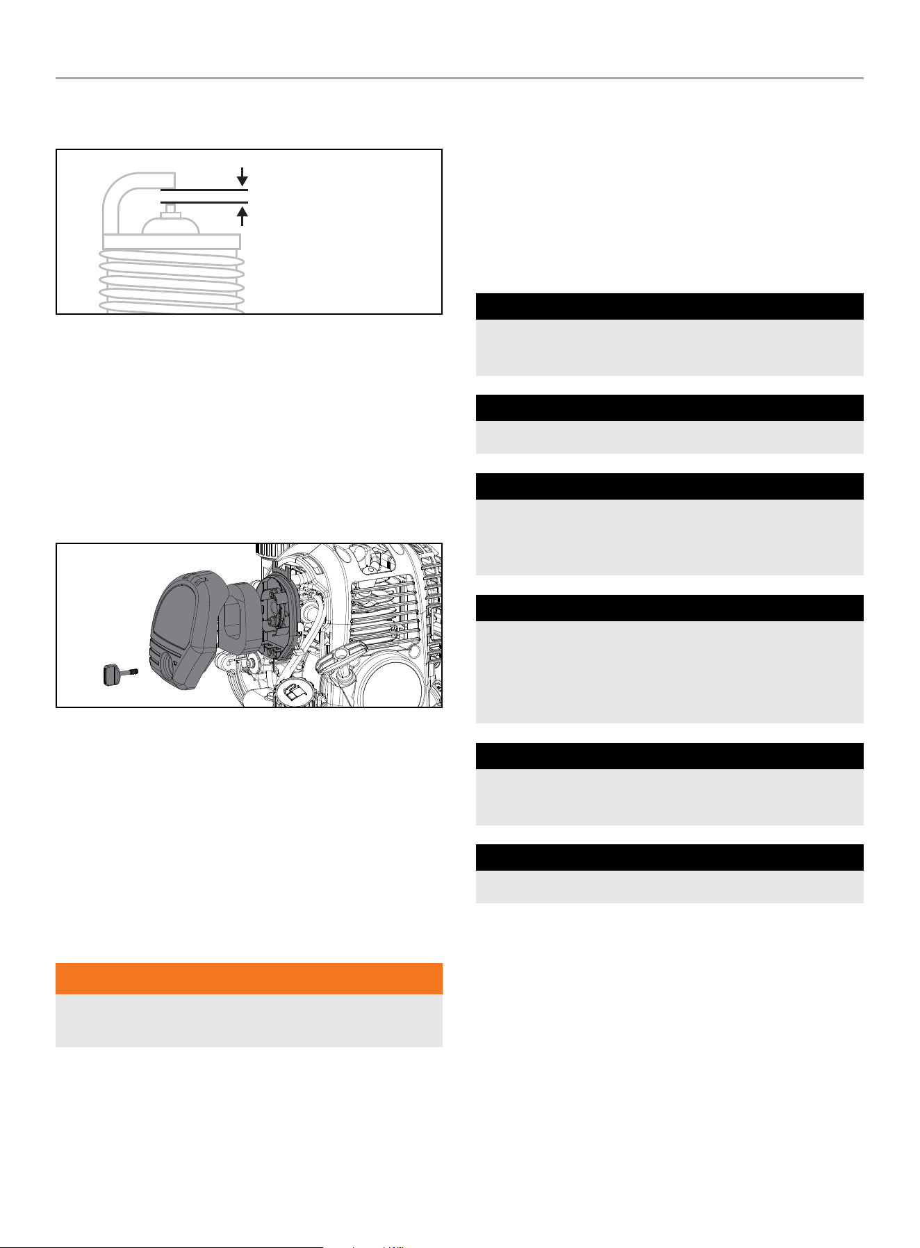
4. Make certain the spark plug gap is 0.6 - 0.8 mm
(0.024 - 0.031 in.).
SPARK PLUG GAP
5. Refer to spark plug section on specifications page.
6. Carefully thread the plug into the engine for replacement
spark plug. (if needed)
7. Use the spark plug tool to firmly re-install the plug.
8. Re-attach the spark plug wire to the plug.
Cleaning the Air Filter
1. Unscrew the air filter wing nut to remove the air filter cover.
2. Remove the foam element.
3. Wash in liquid detergent and water. Squeeze thoroughly dry in
a clean cloth.
4. Saturate in clean engine oil.
5. Squeeze in a clean, absorbent cloth to remove all excess oil.
6. Reassemble the element.
7. Reattach the air filter cover and tighten wing nut.
Adjusting the Governor
WARNING
Tampering with the factory set governor will void your
warranty.
The air-fuel mixture is not adjustable. Tampering with the governor
can damage your water pump and your electrical devices and
will void your warranty. Contact our Technical Support Team at
1-877-338-0999 for all other service and/or adjustment needs.
Maintenance Schedule
Follow the service intervals indicated in the following maintenance
schedule.
Service your water pump more frequently when operating in
adverse conditions.
Contact our Technical Support Team at 1-877-338-0999 to locate
the nearest CPE certified service dealer for your water pump or
engine maintenance needs.
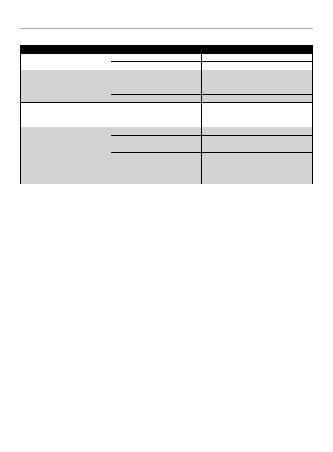
EVERY 8 HOURS OR PRIOR TO EACH USE
Check oil level
Clean around air intake and muffler
FIRST 5 HOURS (BREAK IN)
Change oil
EVERY 50 HOURS OR ANNUALLY
Clean air filter
Change oil if operating under heavy load or in hot
environments
EVERY 100 HOURS OR ANNUALLY
Change oil
Clean/adjust spark plug
Clean spark arrestor
Clean fuel valve filter*
EVERY 250 HOURS
Clean combustion chamber*
Check/adjust valve clearance*
EVERY 3 YEARS
Replace fuel line*
* To be performed by knowledgeable, experienced owners or CPE certified service
centers.
100166 - 1 IN. (2.5 CM) WATER PUMP WITH HOSE KIT
STORAGE
18
STORAGE
For longer term storage, please follow these guidelines.
Engine Storage
1. Allow the engine to cool completely before storage.
2. Clean the engine according to the instructions in the
Maintenance section.
3. Drain all fuel completely from the fuel line and carburetor to
prevent gum from forming.
4. Add a fuel stabilizer into the fuel tank.
5. Change the oil.
6. Remove the spark plug and pour about ½ ounce (14.8 ml) of
oil into the cylinder. Crank the engine slowly to distribute the
oil and lubricate the cylinder.
7. Reattach the spark plug.
Water pump Storage
1. Allow the water pump to cool completely before storage.
2. Turn off the fuel supply at the fuel valve.
3. Drain the pump chamber thoroughly.
4. Clean the water pump according to the instructions in the
Maintenance section.
5. Once the pump is dry, spray WD-40 or similar product into
the pump housing through all ports and drainage hole.
6. Store in a clean, dry place out of direct sunlight.
DANGER
Engine exhaust contains odorless and colorless carbon
monoxide gas.
To avoid accidental or unintended ignition of your product
during periods of storage, the following precautions should be
followed:
– When storing the unit for short or extended periods of time
make sure that the spark plug wire is disconnected.
Winter Storage
Protect your water pump parts from freezing.
1. Apply all storage instructions from previous sections.
2. Make sure water pump hose is free of all water before storing
for winter.
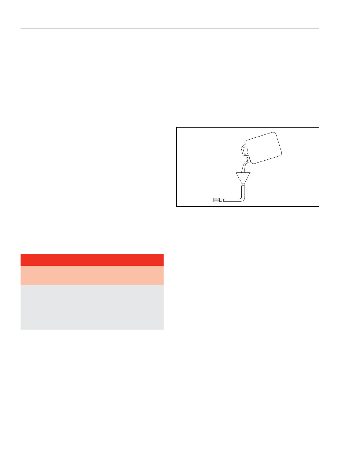
3. In order to prevent the pump from freezing you will need to
insert RV antifreeze.
4. You will need approximately 6 ounces (177.4 ml) of RV
Antifreeze, a funnel, and approximately 12 in. (30.5 cm) of
garden hose or equivalent. See diagram below.
5. Pour the antifreeze into the funnel, then pull on the engine
recoil starter to create suction in the pump housing. Pull the
recoil several times until antifreeze comes out of the pump
outlet. DO NOT START THE ENGINE WHEN DO THIS. Only pull
the recoil cord if the fuel valve and engine switch are in the
OFF position.
100166 - 1 IN. (2.5 CM) WATER PUMP WITH HOSE KIT
SPECIFICATIONS
19
SPECIFICATIONS
Water Pump Specifications
Model
....................................................... 100166
Inlet Diameter - Adapter ............................. 1 in. (2.5 cm)
Inlet Thread Specification:
......................... Thread Designation G1-1/4 in. (31.75 mm)
.................................. Nominal Size 1-1/4 in. (31.75 mm)
............................................ Thread Form Type BSPP
........................................................ Pitch 2.3 mm
Outlet Diameter - Adapter ........................... 1 in. (2.5 cm)
Outlet Thread Specification:
......................... Thread Designation G1-1/4 in. (31.75 mm)
.................................. Nominal Size 1-1/4 in. (31.75 mm)
............................................ Thread Form Type BSPP
........................................................ Pitch 2.3 mm
Total Head ............................................. 95 ft. (29 m)
Suction Head ............................................16 ft. (5 m)
Max Delivery Volume ....................... 30 gal/min (114 L/min)
Weight ..............................................20.5 lb. (9.3 kg)
Length ............................................13.1 in. (33.2 cm)
Width .............................................. 9.7 in. (24.6 cm)
Height .............................................14.2 in. (36.0 cm)
Engine Specifications
Model ........................................................S35-02
Displacement .................................................. 31 cc
Type ................................................... 4-Stroke OHV
Spark Plug
OEM Type .................................................... CMR5H
Gap ................................. 0.024-0.031 in. (0.6-0.8 mm)
Valve
Intake Clearance .............0.002 – 0.003 in. (0.05 – 0.08 mm)
Exhaust Clearance ........... 0.003 – 0.005 in. (0.08 – 0.12 mm)
NOTICE
A technical bulletin regarding valve adjustment procedures is
available at www.championpowerequipment.com.
Oil Specifications
DO NOT OVERFILL.
Type ............................................*See following chart
Capacity .......................................... 2.4 fl. oz. (70 ml)
-20 0 20 40 60
Ambient temperature
Recommended Engine Oil Type
80 100 120
-28.9
°F
°C
-17.8 -6.7 4.4 15.6 26.7 37.8 48.9
10W-30
5W-30 Full Synthetic
10W-405W-30
NOTICE
Temperature will affect engine oil and engine performance.
Change the type of engine oil used based on temperature
shown in the “Recommended Engine Oil Type” table.
Fuel Specifications
Use unleaded gasoline with a minimum octane rating of 87 and
an ethanol content of 10% or less by volume. DO NOT USE E15 or
E85. DO NOT OVERFILL.
Gasoline Capacity ............................. 0.145 gal. (550 mL)
Temperature Specifications
Starting Temperature Range (°F/°C) ........... 5 to 104/-15 to 40
NOTICE
An important message about temperature: Your product
is designed and rated for continuous operation at ambient
temperatures up to 104°F (40°C). When needed, it may be
operated at temperatures ranging from 5°F (-15°C) to 122°F
(50°C) for short periods of time. If exposed to temperatures
outside this range during storage, it should be brought back
within this range before operation. In any event, the product
must always be operated outdoors, in a well-ventilated area
and away from doors, windows and vents.
100166 - 1 IN. (2.5 CM) WATER PUMP WITH HOSE KIT
TROUBLESHOOTING
20
TROUBLESHOOTING
Problem Cause Solution
Water pump will not start
No fuel Add fuel
Faulty spark plug Replace spark plug
Water pump will not start; Water pump
starts but runs roughly
Low oil level
Fill crankcase to the proper level; place water
pump on a flat, level surface
Choke in the wrong position Adjust choke
Spark plug wire loose Attach wire to spark plug
Water pump shuts down during
operation
Out of fuel Fill fuel tank
Low oil level
Fill crankcase to the proper level; place water
pump on a flat, level surface
Water pump overheating or performing
poorly
Strainer or hose clogged Remove debris from strainer or hose
Pump not primed Re-prime pump
Suction hose out of water Place suction hose under the surface of the water
Head limit exceeded
Relocate pump so suction head is less than
discharge head (maximum 98 feet)
Air leak
Tighten connectors and clamps or replace seal
packing, and or apply more telfon tape as needed.
For other issues and technical support:
Technical Support Team
Toll Free 1-877-338-0999
support@championpowerequipment.com

WARRANTY*
CHAMPION POWER EQUIPMENT
2 YEAR LIMITED WARRANTY
Warranty Qualifications
To register your product for warranty and FREE lifetime call center
technical support please visit:
https://www.championpowerequipment.com/register
To complete registration you will need to include a copy of the
purchase receipt as proof of original purchase. Proof of purchase
is required for warranty service. Please register within ten (10)
days from date of purchase.
Repair/Replacement Warranty
CPE warrants to the original purchaser that the mechanical and
electrical components will be free of defects in material and
workmanship for a period of two years (parts and labor) from
the original date of purchase and 180 days (parts and labor) for
commercial and industrial use. Transportation charges on product
submitted for repair or replacement under this warranty are the
sole responsibility of the purchaser. This warranty only applies to
the original purchaser and is not transferable.
Do Not Return The Unit To The Place Of
Purchase
Contact CPE’s Technical Service and CPE will troubleshoot any
issue via phone or e-mail. If the problem is not corrected by
this method, CPE will, at its option, authorize evaluation, repair
or replacement of the defective part or component at a CPE
Service Center. CPE will provide you with a case number for
warranty service. Please keep it for future reference. Repairs or
replacements without prior authorization, or at an unauthorized
repair facility, will not be covered by this warranty.
Warranty Exclusions
This warranty does not cover the following repairs and equipment:
Normal Wear
Products with mechanical and electrical components need
periodic parts and service to perform well. This warranty does not
cover repair when normal use has exhausted the life of a part or
the equipment as a whole.
Installation, Use and Maintenance
This warranty will not apply to parts and/or labor if the product is
deemed to have been misused, neglected, involved in an accident,
abused, loaded beyond the product’s limits, modified, installed
improperly or connected incorrectly to any electrical component.
Normal maintenance is not covered by this warranty and is not
required to be performed at a facility or by a person authorized by
CPE.
Other Exclusions
This warranty excludes:
– Cosmetic defects such as paint, decals, etc.
– Wear items such as filter elements, o-rings, etc.
– Accessory parts such as hoses, hose fittings, etc.
– Failures due to acts of God and other force majeure events
beyond the manufacturer’s control.
– Problems caused by parts that are not original Champion
Power Equipment parts.
When applicable, this warranty does not apply to products used
for prime power in place of a utility.
Limits of Implied Warranty and
Consequential Damage
Champion Power Equipment disclaims any obligation to cover
any loss of time, use of this product, freight, or any incidental
or consequential claim by anyone from using this product.
THIS WARRANTY AND THE ATTACHED U.S. EPA and/or CARB
EMISSION CONTROL SYSTEM WARRANTIES (WHEN APPLICABLE)
ARE IN LIEU OF ALL OTHER WARRANTIES, EXPRESS OR IMPLIED,
INCLUDING WARRANTIES OF MERCHANTABILITY OR FITNESS
FOR A PARTICULAR PURPOSE.
A unit provided as an exchange will be subject to the warranty
of the original unit. The length of the warranty governing the
exchanged unit will remain calculated by reference to the purchase
date of the original unit.
This warranty gives you certain legal rights which may change
from state to state or province to province. Your state or province
may also have other rights you may be entitled to that are not
listed within this warranty.
Contact Information
Address
Champion Power Equipment, Inc.
6370 S Pioneer Way, Unit 101
Las Vegas, NV 89113 USA
www.championpowerequipment.com
Customer Service
Toll Free: 1-877-338-0999
info@championpowerequipment.com
Fax no.: 1-562-236-9429
Technical Service
Toll Free: 1-877-338-0999
tech@championpowerequipment.com
EMERGENCY 24 HOUR SUPPORT: 1-562-204-1188
*Except as otherwise stipulated in any of the following enclosed Emission Control System Warranties (when applicable) for the Emission Control System: U.S. Environment Protection Agency
(EPA) and/or California Air Resources Board (CARB).

CHAMPION POWER EQUIPMENT, INC. (CPE)
AND THE UNITED STATES ENVIRONMENTAL PROTECTION AGENCY (U.S. EPA.)
EMISSION CONTROL SYSTEM WARRANTY
Your Champion Power Equipment (CPE) engine complies with U.S. EPA emissions regulations.
YOUR WARRANTY RIGHTS AND OBLIGATIONS:
The U.S. EPA and CPE are pleased to explain the Federal Emission Control Systems Warranty on your 2025 small off-road engine and
engine powered equipment. New equipment that use small off-road engines must be designed, built and equipped to meet U.S. EPA
regulations.
CPE must warrant the exhaust and evaporative emission control system on your small off-road engine for the period listed below, provided
there has been no abuse, neglect, unapproved modification, or improper maintenance of your equipment.
Your emission control system may include parts such as: carburetors, fuel tanks, fuel lines, (for liquid fuel and fuel vapors), fuel caps,
valves, canisters, filters, clamps, connectors, and other associated components. Also included may be the fuel-injection system, the
ignition system, catalytic converter and other emission related assemblies. Where a warrantable condition exits, CPE will repair your small
off-road engine at no cost to you including diagnosis, parts and labor.
MANUFACTURER’S EMISSION CONTROL SYSTEM WARRANTY COVERAGE:
This emission control system is warranted for two years, subject to provision set forth below. If any emission related part on your engine is
defective, the part will be repaired or replaced by CPE.
OWNER WARRANTY RESPONSIBILITIES:
As the small off-road engine owner, you are responsible for the performance of the required maintenance listed in your Owner’s Manual.
CPE recommends that you retain all your receipts covering maintenance on your small off-road engine, but CPE cannot deny warranty
coverage solely for the lack of receipts or for your failure to ensure the performance of all scheduled maintenance.
As the small off-road engine owner, you should be aware that CPE may deny you warranty coverage if your small off-road engine or a part
has failed due to abuse, neglect, improper maintenance or unapproved modifications.
You are responsible for presenting your small off-road engine to an Authorized CPE distribution center, service center or alternate service
outlet as described in (3)(f) below or CPE dealer or CPE, Las Vegas, NV. as soon as the problem exists. The warranty repairs shall be
completed in a reasonable amount of time, not to exceed 30 days.
If you have any questions regarding your warranty coverage, you should contact:
Champion Power Equipment, Inc.
Customer Service
6370 S Pioneer Way, Unit 101
Las Vegas, NV 89113
1-877-338-0999
tech@championpowerequipment.com

EMISSION CONTROL SYSTEM WARRANTY
The following are specific provisions relative to your Exhaust and Evaporative Emission Control System (ECS) Warranty
Coverage.
1. APPLICABILITY: This warranty shall apply to 1997 and later model year small off-road engines.The ECS Warranty Period shall begin
on the date the new engine is delivered to its original, end-use purchaser, and shall continue for 24 consecutive months thereafter.
2. GENERAL EMISSIONS WARRANTY COVERAGE
CPE warrants to the original, end-use purchaser of the new engine or equipment and to each subsequent purchaser that each of its
small off-road engines is:
2a. Designed, built and equipped to conform to U.S. EPA emissions standards for spark-ignited engines at or below 19 kilowatts.
2b. Free from defects in materials and workmanship that cause the failure of a warranted part to be identical in all material respects
to the part as described in the engine manufacturer’s application for certification for a period of two years.
3. THE WARRANTY ON EMISSION-RELATED PARTS WILL BE INTERPRETED AS FOLLOWS:
3a. Any warranted part that is not scheduled for replacement as required maintenance in the Owner’s Manual shall be warranted for
the ECS Warranty Period. If any such part fails during the ECS Warranty Period, it shall be repaired or replaced by CPE according
to Subsection “d” below. Any such part repaired or replaced under the ECS Warranty shall be warranted for any remainder of the
ECS Warranty Period.
3b. Any warranted, emissions-related part which is scheduled only for regular inspection as specified in the Owner’s Manual shall be
warranted for the ECS Warranty Period. A statement in such written instructions to the effect of “repair or replace as necessary”,
shall not reduce the ECS Warranty Period. Any such part repaired or replaced under the ECS Warranty shall be warranted for the
remainder of the ECS Warranty Period.
3c. Any warranted, emissions-related part which is scheduled for replacement as required maintenance in the Owner’s Manual shall
be warranted for the period of time prior to the first scheduled replacement point for that part. If the part fails prior to the first
scheduled replacement, the part shall be repaired or replaced by CPE according to Subsection “d” below. Any emissions-related
part repaired or replaced under the ECS Warranty, shall be warranted for the remainder of the ECS Warranty Period prior to the
first scheduled replacement point for such emissions-related part.
3d. Repair or replacement of any warranted, emissions-related part under this ECS Warranty shall be performed at no charge to the
owner at a CPE Authorized Service Outlet.
3e. The owner shall not be charged for diagnostic labor which leads to the determination that a part covered by the ECS Warranty is in
fact defective, provided that such diagnostic work is performed at a CPE Authorized Service Outlet.
3f. CPE shall pay for covered emissions warranty repairs at non-authorized service outlets under the following circumstances:
i. The service is required in a population center with a population over 100,000 according to U.S. Census 2000 without a CPE
Authorized Service Outlet AND
ii. The service is required more than 100 miles from a CPE Authorized Service Outlet. The 100 mile limitation does not apply in the
following states: Alaska, Arizona, Colorado, Hawaii, Idaho, Montana, Nebraska, Nevada, New Mexico, Oregon, Texas, Utah and
Wyoming.
3g. CPE shall be liable for damages to other original engine components or approved modifications proximately caused by a failure
under warranty of an emission-related part covered by the ECS Warranty.
3h. Throughout the ECS Warranty Period, CPE shall maintain a supply of warranted exhaust and evaporative emission-related parts
sufficient to meet the expected demand for such exhaust and evaporative emission-related parts.
3i. Any CPE Authorized and approved emission-related replacement part may be used in the performance of any ECS Warranty
maintenance or repair and will be provided without charge to the owner. Such use shall not reduce CPE’s warranty obligation.
3j. Unapproved add-on or modified parts may not be used to modify or repair a CPE engine. Such use voids this ECS Warranty and
shall be sufficient grounds for disallowing an ECS Warranty claim. CPE shall not be liable hereunder for failures of any warranted
parts of a CPE engine caused by the use of such an unapproved add-on or modified part.
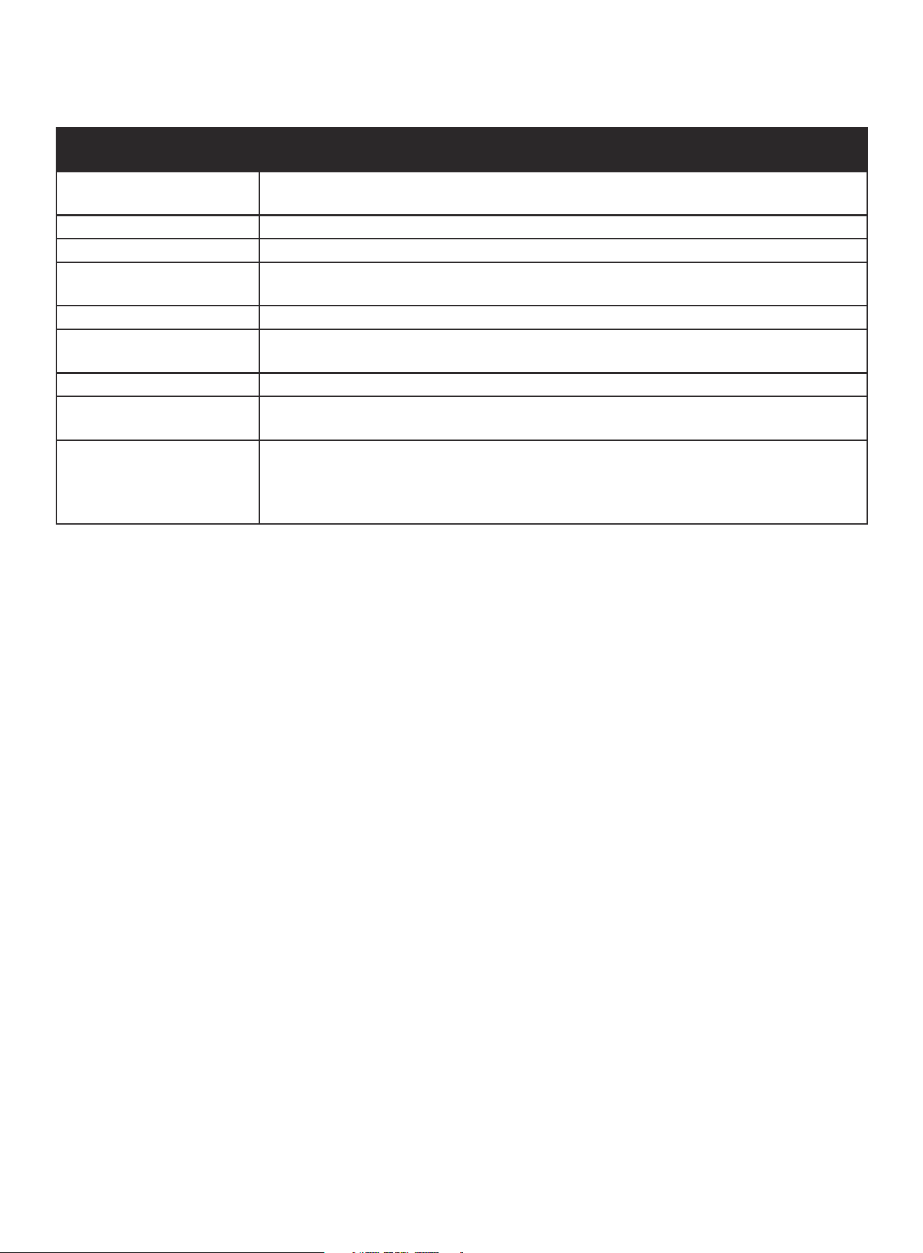
EMISSION-RELATED PARTS INCLUDE THE FOLLOWING: (using those portions of the list applicable to the
engine)
Systems covered by this
warranty
Parts Description
Fuel Metering System Carburetor and internal parts (and/or pressure regulator or fuel injection system) Air/fuel ratio
feedback and control system. Cold start enrichment system.
Air Induction System Controlled hot air intake system. Air Filter, Intake manifold.
Ignition System Spark plug. Magneto or electronic ignition system. Spark advance/retard system.
Exhaust Gas Recirculation (EGR)
System
EGR valve body, and carburetor spacer if applicable. EGR rate feedback and control system.
Air Injection System Air pump or pulse valve. Valves affecting distribution of flow. Distribution manifold.
Catalyst or Thermal Reactor
System
Catalytic converter. Thermal reactor. Exhaust manifold.
Particulate Controls Traps, filters, precipitators, and any other device used to capture particulate emissions.
Miscellaneous Parts Vacuum, temperature, and time sensitive valves and switches. Electronic controls. Hoses, belts,
connectors, and assemblies.
Evaporative Controls Fuel Tank, Fuel Cap, Fuel Lines (for liquid fuel & fuel vapors), Fuel Line Fittings, Clamps, Pressure
Relief Valves, Control Valves, Control Solenoids, Electronic Controls, Vacuum Control Diaphragms,
Control Cables, Control Linkages, Purge Valves, Gaskets, Liquid/Vapor Separator, Carbon Canister,
Canister Mounting Brackets, Carburetor Purge Port Connector.
TO OBTAIN WARRANTY SERVICE:
You must take your CPE engine or the product on which it is installed, along with your warranty registration card or other proof of original
purchase date, at your expense, to any Champion Power Equipment dealer who is authorized by Champion Power Equipment, Inc. to
sell and service that CPE product during his normal business hours. Alternate service locations defined in Section (3)(f) above must be
approved by CPE prior to service. Claims for repair or adjustment found to be caused solely by defects in material or workmanship will not
be denied because the engine was not properly maintained and used.
If you have any questions regarding your warranty rights and responsibilities, or to obtain warranty service, please write or call
Customer Service at Champion Power Equipment, Inc.
Champion Power Equipment, Inc.
6370 S Pioneer Way, Unit 101
Las Vegas, NV 89113
1-877-338-0999
Attn.: Customer Service
tech@championpowerequipment.com

CHAMPION POWER EQUIPMENT, INC. (CPE),
THE UNITED STATES ENVIRONMENTAL PROTECTION AGENCY (U.S. EPA)
AND THE CALIFORNIA AIR RESOURCES BOARD (CARB) EMISSION CONTROL SYSTEM WARRANTY
Your Champion Power Equipment (CPE) engine complies with both the U.S. EPA and state of California Air Resources Board
(CARB) Exhaust and Evaporative emissions regulations.
YOUR WARRANTY RIGHTS AND OBLIGATIONS:
The US EPA, California Air Resources Board, and CPE are pleased to explain the Federal and California Exhaust and Evaporative Emission
Control Systems Warranty on your 2025 small off-road engine (SORE) and engine powered equipment. In California, new equipment that
use small off-road engines (SORE) must be designed, built and equipped to meet the State’s stringent anti-smog standards.
CPE must warrant the exhaust and evaporative emission control system on your small off-road engine (SORE) for the period listed below,
provided there has been no abuse, neglect, unapproved modification, or improper maintenance of your equipment leading to the failure of
the exhaust and evaporative emission control systems.
Your evaporative emission control system may include parts such as: carburetors, fuel tanks, fuel lines, (for liquid fuel and fuel vapors),
fuel caps, valves, canisters, filters, clamps, connectors, and other associated components. Also included for your exhaust emission control
system may be the fuel-injection system, the ignition system, catalytic converter and other exhaust emission related assemblies. Where a
warrantable condition exits, CPE will repair your small off-road engine (SORE) at no cost to you including diagnosis, parts and labor.
MANUFACTURER’S WARRANTY COVERAGE:
This exhaust and evaporative emission control system is warranted for two years. If any exhaust and evaporative, emission related part on
your engine or equipment is defective in, the part will be repaired or replaced by CPE.
OWNER WARRANTY RESPONSIBILITIES:
As the small off-road engine (SORE) owner, you are responsible for the performance of the required maintenance listed in your Owner’s
Manual. CPE recommends that you retain all your receipts covering maintenance on your small off-road engine (SORE), but CPE cannot
deny warranty coverage solely for the lack of receipts.
As the small off-road engine (SORE) owner, you should be aware that CPE may deny you warranty coverage if your small off-road engine
(SORE) or a part has failed due to abuse, neglect, improper maintenance or unapproved modifications.
You are responsible for presenting your small off-road engine to an Authorized CPE distribution center, service center or alternate service
outlet as described in (3)(f) below or CPE dealer or CPE, Las Vegas, NV. as soon as the problem exists. The warranty repairs shall be
completed in a reasonable amount of time, not to exceed 30 days.
If you have any questions regarding your warranty coverage, you should contact:
Champion Power Equipment, Inc.
Customer Service
6370 S Pioneer Way, Unit 101
Las Vegas, NV 89113
1-877-338-0999
tech@championpowerequipment.com

EXHAUST AND EVAPORATIVE EMISSION CONTROL SYSTEM WARRANTY
The following are specific provisions relative to your Exhaust and Evaporative Emission Control System (ECS) Warranty
Coverage.
1. APPLICABILITY: This warranty shall apply to 1995 and later model year California small off-road engines (SORE) (for other states,
1997 and later model year engines). The ECS Warranty Period shall begin on the date the new engine or equipment is delivered to its
original, end-use purchaser, and shall continue for 24 consecutive months thereafter.
2. GENERAL EMISSIONS WARRANTY COVERAGE
CPE warrants to the original, end-use purchaser of the new engine or equipment and to each subsequent purchaser that each of its
small off-road engines (SORE) is:
2a. Designed, built and equipped to conform to U.S. EPA emissions standards for spark-ignited engines at or below 19 kilowatts and
all applicable regulations adopted by the California Air Resources Board and
2b. Free from defects in materials and workmanship that cause the failure of a warranted part to be identical in all material respects
to the part as described in the engine manufacturer’s application for certification for a period of two years.
3. THE WARRANTY ON EXHAUST AND EVAPORATIVE EMISSION-RELATED PARTS WILL BE INTERPRETED AS FOLLOWS:
3a. Any warranted part that is not scheduled for replacement as required maintenance in the Owner’s Manual shall be warranted for
the ECS Warranty Period. If any such part fails during the ECS Warranty Period, it shall be repaired or replaced by CPE according
to Subsection “d” below. Any such part repaired or replaced under the ECS Warranty shall be warranted for any remainder of the
ECS Warranty Period.
3b. Any warranted, exhaust and evaporative emissions-related part which is scheduled only for regular inspection as specified in the
Owner’s Manual shall be warranted for the ECS Warranty Period. A statement in such written instructions to the effect of “repair
or replace as necessary”, shall not reduce the ECS Warranty Period. Any such part repaired or replaced under the ECS Warranty
shall be warranted for the remainder of the ECS Warranty Period.
3c. Any warranted, exhaust and evaporative emissions-related part which is scheduled for replacement as required maintenance in
the Owner’s Manual shall be warranted for the period of time prior to the first scheduled replacement point for that part. If the part
fails prior to the first scheduled replacement, the part shall be repaired or replaced by CPE according to Subsection “d” below.
Any such exhaust and evaporative emissions-related part repaired or replaced under the ECS Warranty, shall be warranted for the
remainder of the ECS Warranty Period prior to the first scheduled replacement point for such emissions-related part.
3d. Repair or replacement of any warranted, exhaust and evaporative emissions-related part under this ECS Warranty shall be
performed at no charge to the owner at a CPE Authorized Service Outlet.
3e. The owner shall not be charged for diagnostic labor which leads to the determination that a part covered by the ECS Warranty is in
fact defective, provided that such diagnostic work is performed at a CPE Authorized Service Outlet.
3f. CPE shall pay for covered exhaust and evaporative emissions warranty repairs at non-authorized service outlets under the
following circumstances:
i. The service is required in a population center with a population over 100,000 according to U.S. Census 2000 without a CPE
Authorized Service Outlet AND
ii. The service is required more than 100 miles from a CPE Authorized Service Outlet. The 100 mile limitation does not apply in the
following states: Alaska, Arizona, Colorado, Hawaii, Idaho, Montana, Nebraska, Nevada, New Mexico, Oregon, Texas, Utah and
Wyoming.
3g. CPE shall be liable for damages to other original engine components or approved modifications proximately caused by a failure
under warranty of an emission-related part covered by the ECS Warranty.
3h. Throughout the ECS Warranty Period, CPE shall maintain a supply of warranted exhaust and evaporative emission-related parts
sufficient to meet the expected demand for such exhaust and evaporative emission-related parts.
3i. Any CPE Authorized and approved exhaust and evaporative emission-related replacement part may be used in the performance
of any ECS Warranty maintenance or repair and will be provided without charge to the owner. Such use shall not reduce CPE’s
warranty obligation.
3j. Unapproved add-on or modified parts may not be used to modify or repair a CPE engine. Such use voids this ECS Warranty and
shall be sufficient grounds for disallowing an ECS Warranty claim. CPE shall not be liable hereunder for failures of any warranted
parts of a CPE engine caused by the use of such an unapproved add-on or modified part.

EMISSION-RELATED PARTS INCLUDE THE FOLLOWING: (using those portions of the list applicable to the
engine)
Systems covered by this
warranty
Parts Description
Fuel Metering System Carburetor and internal parts (and/or pressure regulator or fuel injection system), Air/fuel ratio
feedback and control system, Cold start enrichment system.
Air Induction System Controlled hot air intake system, Intake manifold, Air filter.
Ignition System Spark plug, Magneto or electronic ignition system, Spark advance/retard system.
Exhaust Gas Recirculation (EGR)
System
EGR valve body, and carburetor spacer if applicable, EGR rate feedback and control system.
Air Injection System Air pump or pulse valve, Valves affecting distribution of flow, Distribution manifold.
Catalyst or Thermal Reactor
System
Catalytic Converter, Thermal Reactor, Exhaust Manifold.
Particulate Controls Traps, Filters, Precipitators, and any other device used to capture particulate emissions.
Miscellaneous items used in
Above Systems
Vacuum, Temperature, and time sensitive valves and switches, Electronic Controls, Hoses, Belts,
Connectors, and Assemblies.
Evaporative Controls Fuel Tank, Fuel Cap, Fuel Lines (for liquid fuel and fuel vapors), Fuel Line Fittings, Clamps, Pressure
Relief Valves, Control Valves, Control Solenoids, Electronic Controls, Vacuum Control Diaphragms,
Control Cables, Control Linkages, Purge Valves, Gaskets, Liquid/Vapor Separator, Carbon Canister,
Canister Mounting Brackets, Carburetor Purge Port Connector.
TO OBTAIN WARRANTY SERVICE:
You must take your CPE engine or the product on which it is installed, along with your warranty registration card or other proof of original
purchase date, at your expense, to any Champion Power Equipment dealer who is authorized by Champion Power Equipment, Inc. to
sell and service that CPE product during his normal business hours. Alternate service locations defined in Section (3)(f) above must be
approved by CPE prior to service. Claims for repair or adjustment found to be caused solely by defects in material or workmanship will not
be denied because the engine was not properly maintained and used.
If you have any questions regarding your warranty rights and responsibilities, or to obtain warranty service, please write or call
Customer Service at Champion Power Equipment, Inc.
Champion Power Equipment, Inc.
6370 S Pioneer Way, Unit 101
Las Vegas, NV 89113
1-877-338-0999
Attn.: Customer Service
tech@championpowerequipment.com