
PN-L862B
PN-L752B
PN-L652B
LCD MONITOR
OPERATION MANUAL

IMPORTANT:
To aid reporting in case of loss or theft, please record the
product’s model and serial numbers in the space provided.
The numbers are located in the rear of the product.
Model No.:
Serial No.:
U.S.A. ONLY
3
E
IMPORTANT INFORMATION
WARNING: TO REDUCE THE RISK OF FIRE OR ELECTRIC SHOCK, DO NOT EXPOSE THIS PRODUCT
TO RAIN OR MOISTURE.
CAUTION: TO REDUCE THE RISK OF ELECTRIC
SHOCK, DO NOT REMOVE COVER.
NO USER-SERVICEABLE PARTS
INSIDE.
REFER SERVICING TO QUALIFIED
SERVICE PERSONNEL.
The lightning flash with arrowhead symbol, within
a triangle, is intended to alert the user to the
presence of uninsulated “dangerous voltage”
within the product’s enclosure that may be of
sufficient magnitude to constitute a risk of electric
shock to persons.
The exclamation point within a triangle is
intended to alert the user to the presence of
important operating and maintenance (servicing)
instructions in the literature accompanying the
product.
To maintain compliance with EMC regulations, use shielded cables to connect to the following terminals: HDMI input terminal,
D-sub input terminal, RS-232C input terminal, USB Type C port, TOUCH PANEL terminal, and USB port.
CAUTION
RISK OF ELECTRIC
SHOCK
DO NOT OPEN
WARNING:
FCC Regulations state that any unauthorized changes or modifications to this equipment not expressly approved by the
manufacturer could void the user’s authority to operate this equipment.
NOTE:
This equipment has been tested and found to comply with the limits for a Class A digital device, pursuant to Part 15 of the
FCC Rules. These limits are designed to provide reasonable protection against harmful interference when the equipment
is operated in a commercial environment. This equipment generates, uses, and can radiate radio frequency energy and, if
not installed and used in accordance with the instruction manual, may cause harmful interference to radio communications.
Operation of this equipment in a residential area is likely to cause harmful interference in which case the user will be required
to correct the interference at his own expense.
U.S.A. ONLY

4
E
Thank you for your purchase of a SHARP LCD product. To ensure safety and many years of trouble-free operation of your
product, please read the Safety Precautions carefully before using this product.
SAFETY PRECAUTIONS
Electricity is used to perform many useful functions, but it can also cause personal injuries and property damage if improperly
handled. This product has been engineered and manufactured with the highest priority on safety. However, improper use can
result in electric shock and/or fire. In order to prevent potential danger, please observe the following instructions when installing,
operating and cleaning the product. To ensure your safety and prolong the service life of your LCD product, please read the
following precautions carefully before using the product.
1. Read instructions — All operating instructions must be read and understood before the product is operated.
2. Keep this manual in a safe place — These safety and operating instructions must be kept in a safe place for future
reference.
3. Observe warnings — All warnings on the product and in the instructions must be observed closely.
4. Follow instructions — All operating instructions must be followed.
5. Cleaning — Unplug the power cord from the power outlet before cleaning the product. Use a dry cloth to clean the product.
Do not use liquid cleaners or aerosol cleaners. Do not use dirty cloths. Doing so may damage the product.
6. Attachments — Do not use attachments not recommended by the manufacturer. Use of inadequate attachments can result
in accidents.
7. Water and moisture — Do not use the product near water. Do not install the product in a place where water may splash onto
it. Be careful of equipment which drains water such as an air-conditioner.
8. Ventilation — The vents and other openings in the cabinet are designed for ventilation.
Do not cover or block these vents and openings since insufficient ventilation can cause overheating and/or shorten the life
of the product. Do not place the product on a sofa, rug or other similar surface, since they can block ventilation openings.
Do not place the product in an enclosed place such as a bookcase or rack, unless proper ventilation is provided or the
manufacturer’s instructions are followed.
9. Power cord protection — The power cords must be routed properly to prevent people from stepping on them or objects from
resting on them.
10. The screen used in this product is made of glass. Therefore, it can break when the product is dropped or applied with
impact. Be careful not to be injured by broken glass pieces in case the screen breaks.
11. Overloading — Do not overload power outlets or extension cords. Overloading can cause fire or electric shock.
12. Entering of objects and liquids — Never insert an object into the product through vents or openings. High voltage flows in
the product, and inserting an object can cause electric shock and/or short internal parts.
For the same reason, do not spill water or liquid on the product.
13. Servicing — Do not attempt to service the product yourself. Removing covers can expose you to high voltage and other
dangerous conditions. Request a qualified service person to perform servicing.
14. Repair — If any of the following conditions occurs, unplug the power cord from the power outlet, and request a qualified
service person to perform repairs.
a. When the power cord or plug is damaged.
b. When a liquid was spilled on the product or when objects have fallen into the product.
c. When the product has been exposed to rain or water.
d. When the product does not operate properly as described in the operating instructions.
Do not touch the controls other than those described in the operating instructions. Improper adjustment of controls
not described in the instructions can cause damage, which often requires extensive adjustment work by a qualified
technician.
e. When the product has been dropped or damaged.
f. When the product displays an abnormal condition. Any noticeable abnormality in the product indicates that the product
needs servicing.
15. Replacement parts — In case the product needs replacement parts, make sure that the service person uses replacement
parts specified by the manufacturer, or those with the same characteristics and performance as the original parts. Use of
unauthorized parts can result in fire, electric shock and/or other danger.
16. Safety checks — Upon completion of service or repair work, request the service technician to perform safety checks to
ensure that the product is in proper operating condition.
17. Wall mounting — When mounting the product on a wall, be sure to install the product according to the method
recommended by the manufacturer.
18. Heat sources — Keep the product away from heat sources such as radiators, heaters, stoves and other heat-generating
products (including amplifiers).
DEAR SHARP CUSTOMER
5
E
SAFETY PRECAUTIONS (Continued)
19. Batteries — Incorrect use of batteries may cause the batteries to burst or ignite. A leaky battery may corrode the equipment,
dirty your hands or spoil your clothing. In order to avoid these problems, make sure to observe the precautions below:
• Use the specified batteries only.
• Install the batteries with due attention to the plus (+) and minus (-) sides of the batteries according to the instructions in the
compartment.
• Do not mix old and new batteries.
• Do not mix batteries of different types. Voltage specifications of batteries of the same shape may vary.
• Replace an exhausted battery with a new one promptly.
• If you will not use the remote control for a long time, remove the batteries.
• If leaked battery fluid gets on your skin or clothing, rinse immediately and thoroughly. If it gets into your eye, bathe your
eye well rather than rubbing and seek medical treatment immediately. Leaked battery fluid that gets into your eye or your
clothing may cause a skin irritation or damage your eye.
20. Usage of the monitor must not be accompanied by fatal risks or dangers that, could lead directly to death, personal injury,
severe physical damage or other loss, including nuclear reaction control in nuclear facility, medical life support system, and
missile launch control in a weapon system.
21. Do not stay in contact with the parts of the product that become hot for long periods of time. Doing so may result in
low-temperature burns.
22. Do not modify this product.
WARNING:
This is a Class A product. In a domestic environment this product may cause radio interference in which case the user may
be required to take adequate measures.
An apparatus with CLASS I construction shall be connected to a MAIN socket outlet with a protective earthing connection.
STABILITY HAZARD
If a monitor is not positioned in a sufficiently stable location, it can be potentially hazardous due to falling. Many injuries,
particularly to children, can be avoided by taking simple precautions such as:
• Using fixing devices like wall mount brackets recommended by the manufacturer.
• Only using furniture that can safely support the monitor.
• Ensuring the monitor is not overhanging the edge of the supporting furniture.
• Not placing the monitor on tall furniture (for example, cupboards or bookcases) without anchoring both the furniture and the
monitor to a suitable support.
• Not standing the monitors on cloth or other materials placed between the monitor and supporting furniture.
• Educating children about the dangers of climbing on furniture to reach the monitor or its controls.
• This equipment is not suitable for use in locations where children are likely to be present unsupervised.
Especially for child safety
- Don’t allow children to climb on or play with the monitor.
- Don’t place the monitor on furniture that can easily be used as steps, such as a chest of drawers.
- Remember that children can become excited while watching a program, especially on a “larger than life” monitor. Care
should be taken to place or install the monitor where it cannot be pushed, pulled over, or knocked down.
- Care should be taken to route all cords and cables connected to the monitor so that they cannot be pulled or grabbed by
curious children.

6
E
-
The TFT color LCD panel used in this monitor is made with
the application of high precision technology. However, there
may be minute points on the screen where pixels never light
or are permanently lit. Also, if the screen is viewed from an
acute angle there may be uneven colors or brightness. Please
note that these are not malfunctions but common phenomena
of LCDs and will not affect the performance of the monitor.
- Do not display a still picture for a long period, as this could
cause a residual image.
- Never rub or tap the monitor with hard objects.
- Please understand that SHARP CORPORATION bears no
responsibility for errors made during use by the customer or
a third party, nor for any other malfunctions or damage to this
product arising during use, except where indemnity liability is
recognized under law.
- This monitor and its accessories may be upgraded without
advance notice.
-
Do not use the monitor where there is a lot of dust, where humidity
is high, or where the monitor may come into contact with oil or
steam. Do not use in an environment where there are corrosive
gases (sulfur dioxide, hydrogen sulfide, nitrogen dioxide, chlorine,
ammonia, ozone, etc.). As this could lead to fire.
- Ensure that the monitor does not come into contact with
water or other fluids. Ensure that no objects such as paper
clips or pins enter the monitor as this could lead to fire or
electric shock.
- Do not place the monitor on top of unstable objects or in
unsafe places. Do not allow the monitor to receive strong
shocks or to strongly vibrate. Causing the monitor to fall or
topple over may damage it.
- Do not use the monitor near heating equipment or in places
where there is likelihood of high temperature, as this may
lead to generation of excessive heat and outbreak of fire.
- Do not use the monitor in places where it may be exposed to
direct sunlight. Risk of cabinet deformation and failure if the
monitor is used in direct sunlight.
- Please be sure to constantly remove dust and garbage that
has attached to the ventilation opening. If dust collects in the
ventilation opening or the inside of the monitor, it may lead to
excessive heat, outbreak of fire, or malfunction.
Please request a cleaning of the inside of the monitor from
an authorized SHARP servicing dealer or service center.
- The power outlet shall be installed near the equipment and
shall be easily accessible.
- Continuous operating time and warranty.
This product is designed for a maximum daily use of 16
hours. Continual use in excess of 16 hours per day is not
covered by the warranty.
- Do not touch the screen when turning on the monitor, it will
lead to a malfunction. When this occurs, turn the monitor
power off and then on.
- Do not operate the screen with a hard or pointed object such
as a fingernail or pencil.
- Depending on the application used, the touch pen may not
function.
- If another USB device is connected to the computer to which
the touch panel is connected, do not operate the USB device
during touch panel input. Input may not take place correctly.
- Restarting the Android system.
To maintain stable operation of APPLICATION mode, the
Android system must be restarted once a day.
If “Power Save Mode” is on, turn off the power.
If “Power Save Mode” is off, turn off the main power.
- If you or a third party uses the product incorrectly, or if the
product is subjected to the effects of static electricity or
electrical noise, or if the product malfunctions or is repaired,
there is a risk that saved data will be corrupted or lost.
- Always back up important data to a USB flash drive.
- We bear no responsibility for protection of internal memory
recorded content or related damages.
The Power Cord
- Use only the power cord supplied with the monitor.
- Do not damage the power cord nor place heavy objects on
it, stretch it or over bend it. Also, do not add extension cords.
Damage to the cord may result in fire or electric shock.
- Do not use the power cord with a power tap.
Adding an extension cord may lead to fire as a result of
overheating.
- Do not remove or insert the power plug with wet hands.
Doing so could result in electric shock.
- Unplug the power cord if it is not used for a long time.
- Do not attempt to repair the power cord if it is broken
or malfunctioning. Refer the servicing to the service
representative.
Network
- When you use a network, your communication data is
exposed to the risks of being stolen or illegally accessed.
To avoid these risks, you need to use this monitor in a secure
network environment.
Manual Scope
- Microsoft and Windows are either registered trademarks or
trademarks of Microsoft Corporation in the United States
and/or other countries.
- Apple, Mac and macOS are trademarks of Apple Inc.,
registered in the U.S. and other countries.
- The terms HDMI, HDMI High-Definition Multimedia Interface,
and the HDMI Logo are trademarks or registered trademarks
of HDMI Licensing Administrator, Inc.
- DisplayPort is a registered trademark of Video Electronics
Standards Association.
- Google, Chrome OS and Android are trademarks or
registered trademarks of Google LLC.
- Ethernet is a registered trademark of Xerox Corporation.
- VESA is either registered trademark or trademark of Video
Electronics Standards Association in the United States and/
or other countries.
- Bluetooth is a registered trademark of Bluetooth SIG, Inc.
- Arm and Cortex are registered trademarks of Arm Limited (or
its subsidiaries) in the US and/or elsewhere.
- All other brand and product names are trademarks or
registered trademarks of their respective holders.
- Illustrations in this manual may not exactly represent the
actual product or display.
LED Backlight
● TheLEDbacklightinthisproducthasalimitedlifetime.
* If the screen gets dark or does not turn on, it may be
necessary to replace the LED backlight.
* This LED backlight is exclusive to this product and must
be replaced by an authorized SHARP servicing dealer
or service center. Please contact an authorized SHARP
servicing dealer or service center for assistance.
TIPS AND SAFETY INSTRUCTIONS
7
E
MOUNTING PRECAUTIONS
• This product is for use indoors.
•
A mounting bracket compliant with VESA specifications is required.
• Since the monitor is heavy, consult your dealer before
installing, removing or moving the monitor.
•
Mounting the monitor on the wall requires special expertise
and the work must be performed by an authorized SHARP
dealer. You should never attempt to perform any of this work
yourself. Our company will bear no responsibility for accidents
or injuries caused by improper mounting or mishandling.
•
Use the monitor with the surface perpendicular to a level surface.
If necessary, the monitor may be tilted up to 5 degrees upward.
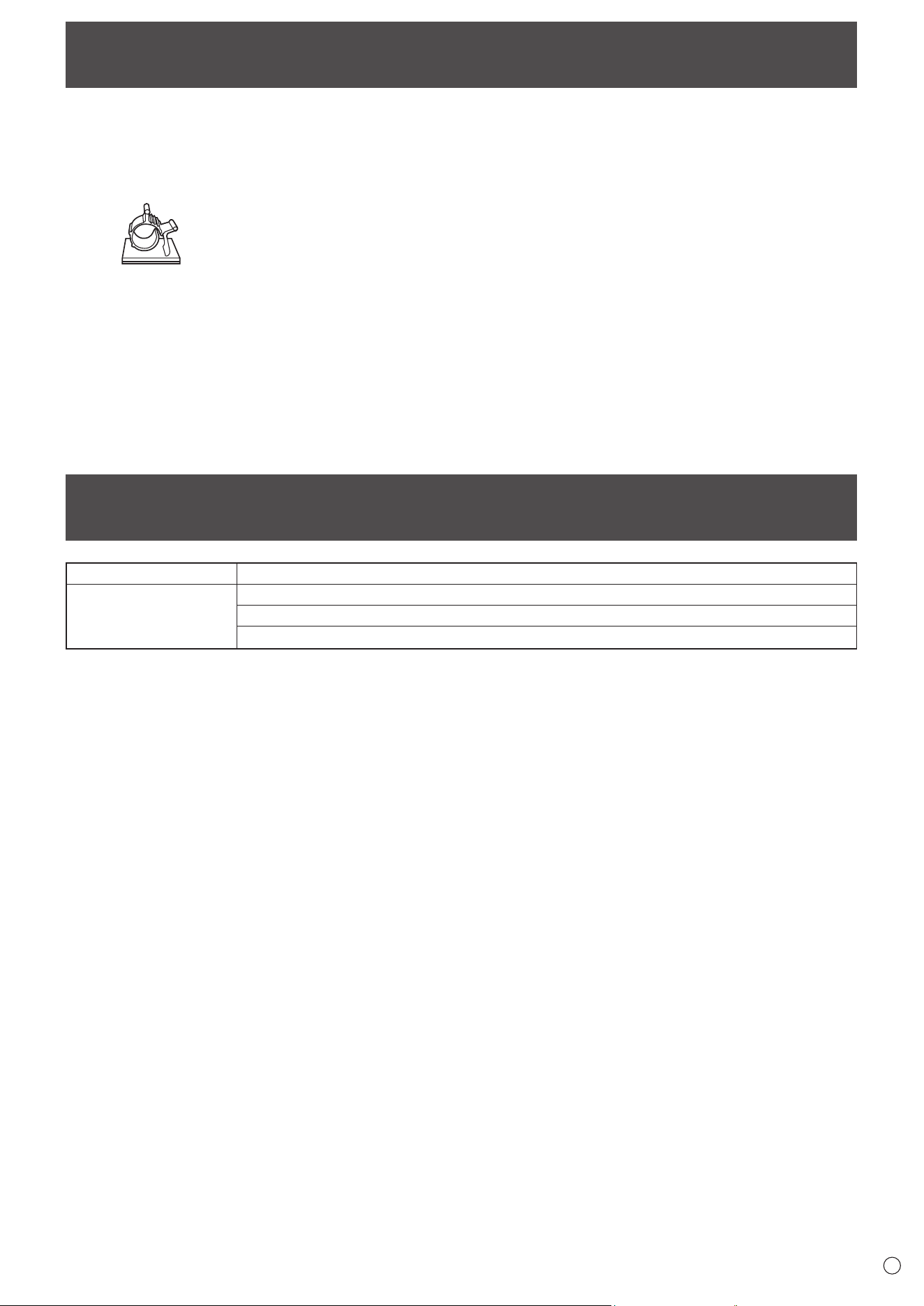
• When moving the monitor, be sure to hold the areas shown
in the figure below. Do not grasp the screen. This may
cause product damage, failure, or injury.
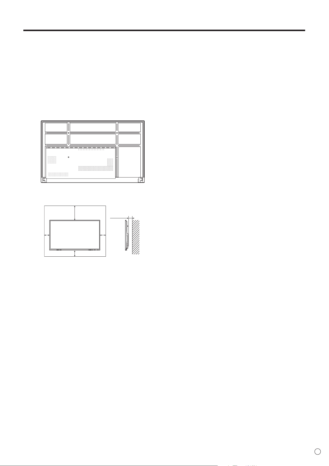
•
This monitor should be used at an ambient temperature
between 41°F (5°C) and 95°F (35°C). Provide enough space
around the monitor to prevent heat from accumulating inside.
Unit: inch [mm]
7-7/8 [200]
2 [50]
2
[50]
2
[50]
1-7/16 [35]
• If it is difficult to provide sufficient space for any reason
such as the installation of the monitor inside a housing or
of several units side-by-side, or if the ambient temperature
may be outside of the range of 41°F (5°C) to 95°F (35°C),
install a fan or take other measures to keep the ambient
temperature within the required range.
• When installing two or more monitor units side-by-side,
provide space of at least 3/16 inch (5 mm) around them
to prevent stress on the adjacent unit or structure due to
thermal expansion.
• Temperature condition may change when using the monitor
together with the optional equipments recommended by
SHARP. In such cases, please check the temperature
condition specified by the optional equipments.
• Do not block any ventilation openings. If the temperature
inside the monitor rises, this could lead to a malfunction.
• Do not place the monitor on a device which generates heat.
• Do not use the product in locations where the unit is
exposed to direct sunlight or other strong light. Since this
product operates with infrared rays, such light may cause a
malfunction.
• When using multiple monitors closely, be sure the infrared
transmitter/receiver does not affect the other ones.

8
E
Contents
IMPORTANT INFORMATION ............................................ 3
DEAR SHARP CUSTOMER ..............................................4
SAFETY PRECAUTIONS ..................................................4
TIPS AND SAFETY INSTRUCTIONS ...............................6
MOUNTING PRECAUTIONS ............................................7
Supplied Components ..................................................... 9
System Requirements .....................................................9
Part Names .....................................................................10
Connecting Peripheral Equipment ...............................12
Connecting the Power Cord .........................................14
Binding Cables ............................................................... 14
Preparing the Remote Control Unit .............................. 15
Installing the batteries ................................................15
Remote control operation range .................................15
Mounting a web camera ................................................16
Attaching the wireless adapter ..................................... 17
Turning Power On/Off .................................................... 18
Turning on the main power.........................................18
Turning power on .......................................................18
Turning power off .......................................................19
Sleep (Backlight off) ...................................................19
Touch Pen ....................................................................... 20
Touch action ................................................................... 21
Touch action ...............................................................21
Cautionary points .......................................................21
Basic Operation .............................................................22
About the home screen of APPLICATION mode ........ 22
Using the remote control unit .....................................24
Overlay board (Mark) .................................................27
Freeze ........................................................................28
Whiteboard .....................................................................29
Drawing ......................................................................31
Erasing a drawn line ...................................................31
Actions using your finger (gesture) ............................32
Opening a PDF or image on the current sheet ..........32
Opening a file .............................................................32
Saving a sheet ...........................................................33
Erasing all lines drawn on the current sheet ..............33
Clearing a PDF or an image opened on the current
sheet ..........................................................................33
Deleting a sheet .........................................................33
Settings ......................................................................34
Bytello Share ..................................................................35
PDF Viewer .....................................................................37
File Explorer ...................................................................38
Web Browser ..................................................................40
Updating the Software (Update) ...................................41
Common Settings Menu ................................................ 42
Displaying the menu screen ....................................... 42
Menu item details .......................................................42
Adjustments for computer screen display ..................44
Administrator Settings Menu ........................................ 45
Displaying the menu screen ....................................... 45
Menu item details .......................................................46
Reset/Functional Restriction Setting (FUNCTION
Menu) ..............................................................................50
Controlling the Monitor with a computer (RS-232C)
...51
Computer connection .................................................51
Communication conditions .........................................51
Communication procedure .........................................51
RS-232C command table ........................................... 53
Troubleshooting .............................................................55
Specifications ...............................................................57
Intellectual Property Rights and Other Matters ..........62
Mounting Precautions
(For SHARP dealers and service engineers) ............... 63
9
E
Hardware Must have a USB 2.0 compliant port.
Operating system
Windows 8.1, Windows 10, Windows 11
macOS v10.15, v11, v12
Google Chrome OS Version 87 or later
To use the touch panel with an HDMI / D-sub connection, connect the supplied USB cable to the computer.
The touch panel and touch pen operate with the standard driver of each operating system. On the Mac, operation is only
possible in mouse mode.
The Information Display Downloader can also be downloaded from the following website.
https://business.sharpusa.com/product-downloads
When the Information Display Downloader is installed, you can check and download the most recent versions of the software
programs.
To install the software, see the manual for each.
Pen Software setup program and Touch Viewer setup program can be downloaded using Information Display Downloader.
Supplied Components
If any component should be missing, please contact your dealer.
Liquid Crystal Display Monitor: 1
Remote control unit: 1
Cable clamp: 4
Power cord: 1
Remote control unit battery: 2
Setup Manual: 1
Touch pen: 2
Camera mount: 1
Camera mount screw (M3x10): 2
Camera screw (inch thread): 1
Player mount: 1
Player mount screw (M3x6): 2
Wireless adapter: 1
USB cable: 1
Cover SHARP logo: 1
Place this sticker onto the SHARP logo to cover the logo.
* For environmental protection!
Do not dispose of batteries in household waste. Follow the disposal instructions for your area.
System Requirements
10
E
n
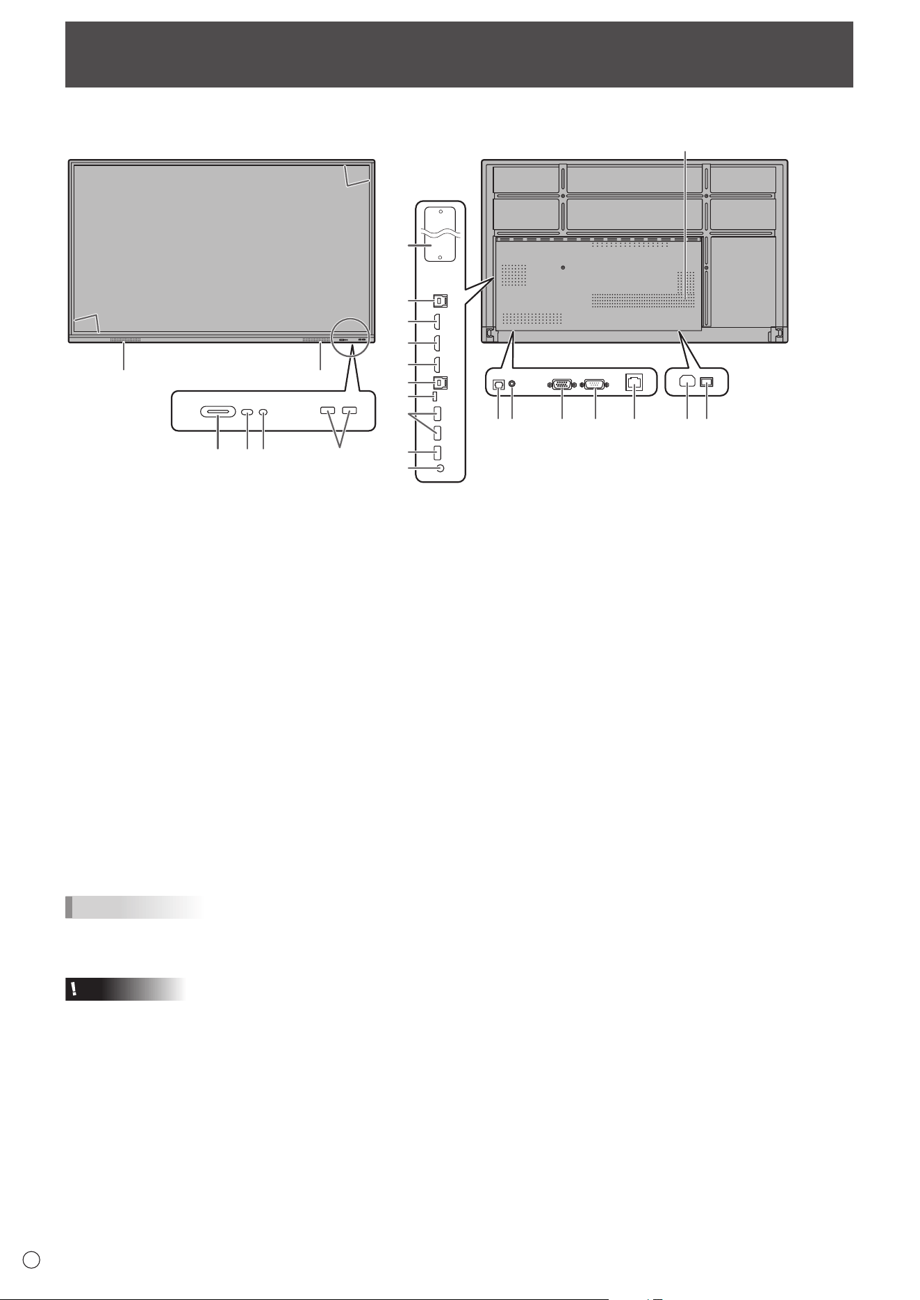
Front view
n
Rear view
22
7
8
9
10
6
11
3
44
3
2**1
5
5
1415 16 17 18
21
12
13
19 20
Part Names
1. POWER button / Power LED (See page 18.)
2. Remote control sensor (See page 15.)
3. USB port (USB 3.0 compliant) (See page 13.)
4. Speakers
5. Infrared transmitter/receiver
6. TOUCH PANEL1 terminal (See page 12.)
7. HDMI1 input terminal (See page 12.)
8. HDMI2 input terminal (See page 12.)
9. HDMI3 input terminal (See page 12.)
10. TOUCH PANEL2 terminal (See page 12.)
11. USB Type C port (See page 12.)
12. USB port (USB 2.0 compliant) (See page 13.)
13. Audio output terminal (See page 13.)
14. Digital audio output (optical) terminal (See page 13.)
15. Audio input terminal (See page 12.)
16. D-sub input terminal (See page 12.)
17. RS-232C input terminal (See page 13.)
18. LAN terminal (See page 13.)
19. AC input terminal (See page 14)
20. Main power switch (See page 18.)
21. Vents
22. Expansion slot
This section is used to connect optional hardware for
function expansion. Offering this attachment location
is not a guarantee that future compatible hardware
attachments will be released.
If a Windows computer is using the OPS slot, this monitor
will not enter standby state while displaying the Windows
Login screen.
* If you turn off the monitor while OPS Module is in
sleep mode, the OPS module may malfunction. Do not
perform the following operations or settings on the OPS
Module.
• Go to sleep mode.
• Turn off the monitor.
** This is not used with this monitor.
TIPS
• It is possible to use the terminals for separate purposes; for example, using the TOUCH PANEL2 terminal to connect a fixed
computer and using the TOUCH PANEL1 terminal to connect a mobile computer.
Caution
• Consult your SHARP dealer for attachment/detachment of optional parts.
11
E
Part Names
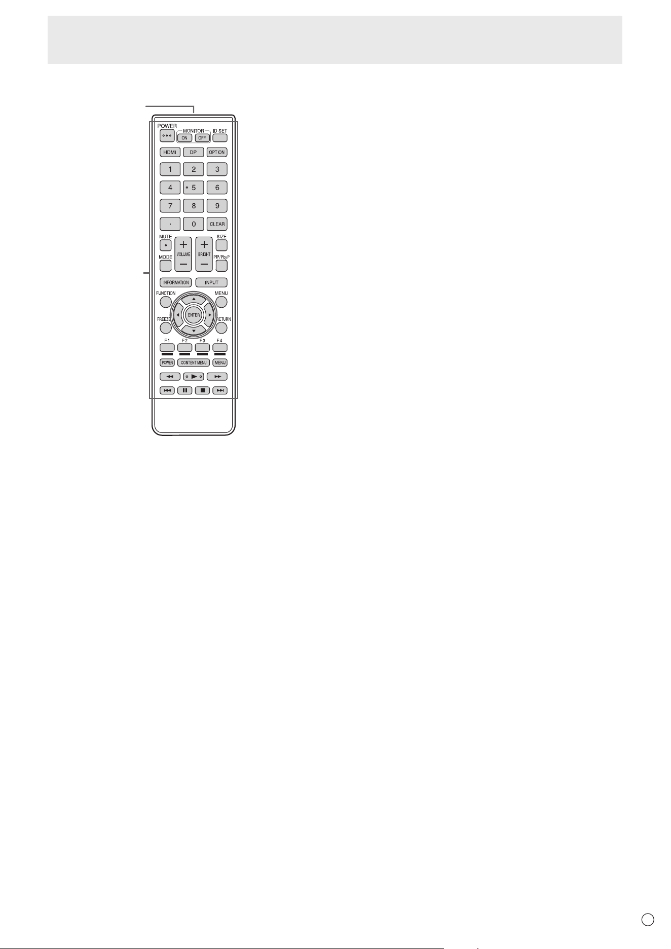
n
Remote control unit
2
1
1. Signal transmitter
2. Operation buttons (See page 24.)
12
E
1
2
3
7
6
4
13
14
10 8511 12
13
9
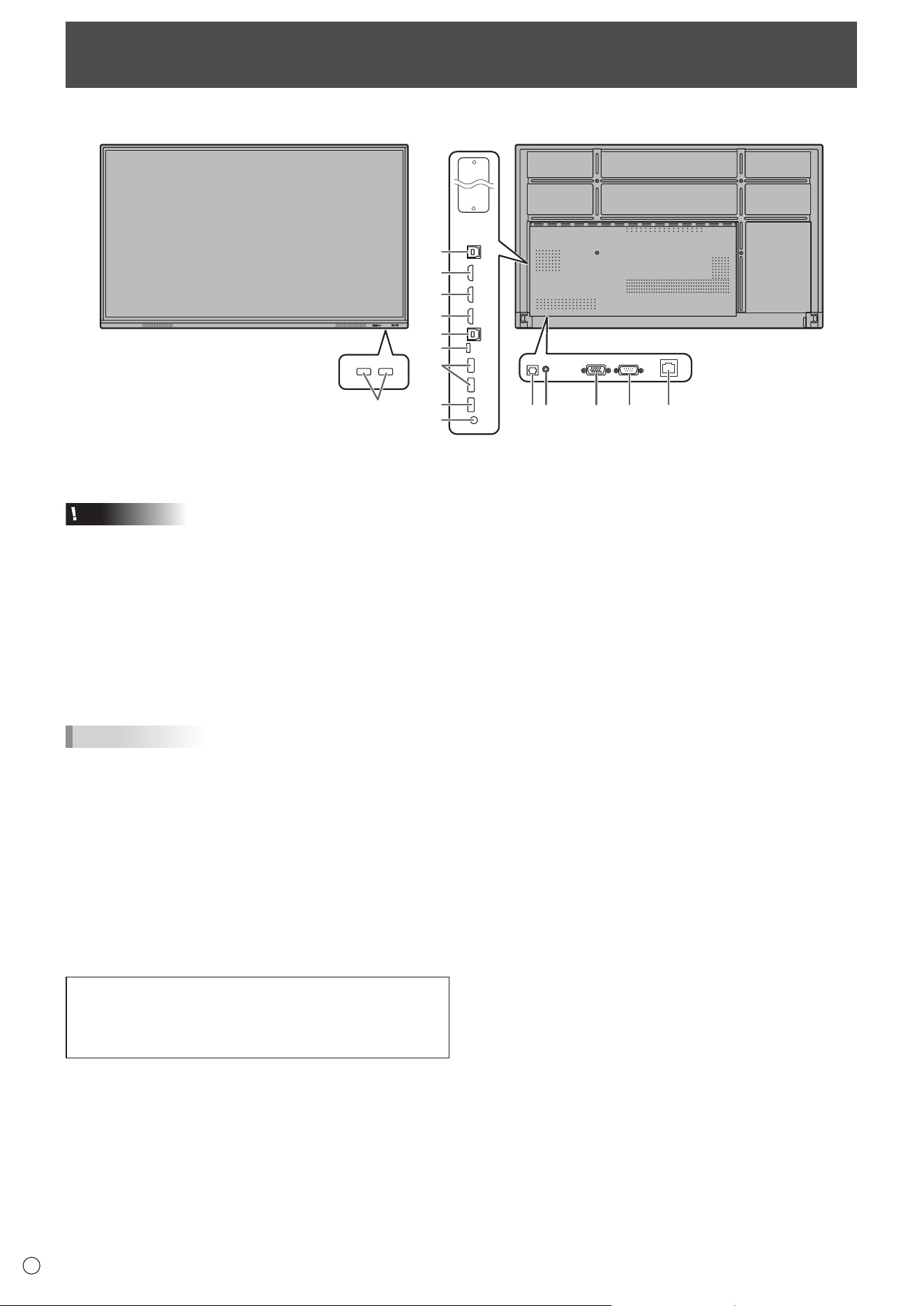
Connecting Peripheral Equipment
Caution
• Be sure to turn off the main power switch and disconnect
the plug from the power outlet before connecting/
disconnecting cables. Also, read the manual of the
equipment to be connected.
• Be careful not to confuse the input terminal with the output
terminal when connecting cables. Accidentally reversing
cables connected to the input and output terminals may
cause malfunctions and the other problems.
• Do not use any cable that has a damaged or deformed
terminal. Using such cables may cause malfunctions.
TIPS
• Images may not be displayed properly depending on the
computer (video card) to be connected.
• Use the automatic screen adjustment when a computer
screen is displayed for the first time using D-SUB or when
the setting of the computer is changed.
• If the audio output from the playback device is connected
directly to speakers or other devices, the video on the
monitor may appear delayed from the audio portion.
Audio should be played through this monitor by connecting
the playback device to the monitor’s audio input, and
connecting the monitor’s audio output to the speakers or
other devices.
The TOUCH PANEL terminal is USB3.0 Type B.
Although the connector shape is different, the supplied
USB cable (USB 2.0 Type B) can be connected to the
TOUCH PANEL terminal.
1. HDMI1 input terminal (support HDMI CEC)
2. HDMI2 input terminal
3. HDMI3 input terminal
• Use a commercially available HDMI cable (conforming to
the HDMI standard) that supports 4K.
4. USB Type C port
• Connect to the computer with a commercially available
USB cable (type C).
• You can connect a device that supports DisplayPort
alternate mode. In order to supply power to connected
devices, it is necessary to support the Power delivery
standard.
• There is no need to connect the USB cable to the TOUCH
PANEL terminal.
• When input mode is change to USB-C, this monitor will be
recognized by the connected computer.
5. D-sub input terminal
6. TOUCH PANEL1 terminal
• To use the touch panel with a computer connected to
an HDMI1 input terminal or an HDMI2 input terminal,
connect the touch panel to the computer with a USB cable
(USB2.0 Type B or USB3.0 Type B).
7. TOUCH PANEL2 terminal
• To use the touch panel with a computer connected to an
HDMI3 input terminal or a D-sub input terminal, connect
the touch panel to the computer with a USB cable
(USB2.0 Type B or USB3.0 Type B).
8. Audio input terminal
• Use an audio cable without resistance.
n
Front view
n
Rear view
13
E
Connecting Peripheral Equipment
9. Audio output terminal
• The output sound varies depending on the input mode.
• The volume of the output sound can be fixed by setting
“Audio Output” of “Input & Output” on the Administrator
Settings menu.
• It is not possible to control the sound output from the
audio output terminals with the Audio menu.
10. Digital audio output (optical) terminal
• Audio that is input into the monitor is output.
• Connect using a commercially available audio digital
cable.
• The output sound varies depending on the input mode.
11. RS-232C input terminal
• You can control the monitor from a computer by
connecting a commercially available RS-232 straight
cable between these terminals and the computer.
12. LAN terminal
• You can connect to a network by using a commercially
available LAN cable.
13. USB port (USB3.0 compliant, Type-A)
• When the input mode is HDMI1 or HDMI2, the USB port
can be used for a computer connected to the TOUCH
PANEL1 terminal.
• When the input mode is HDMI3 or D-SUB, the USB port
can be used for a computer connected to the TOUCH
PANEL2 terminal.
• When the input mode is APPLICATION, the USB port can
be used for APPLICATION mode.
Caution
• Do not switch the input mode when a USB flash drive is
connected. This could corrupt the data on the USB flash
drive. Switch the input mode after removing the USB flash
drive. To save data to the USB flash drive, connect the USB
flash drive to the USB port (USB2.0 compliant, Type-A).
14. USB port (USB2.0 compliant, Type-A)
• The USB port can be used for APPLICATION mode.
n
USB port for the APPLICATION mode
• Connect USB devices (memory device, keyboard, mouse)
that you want to use in “APPLICATION” mode.
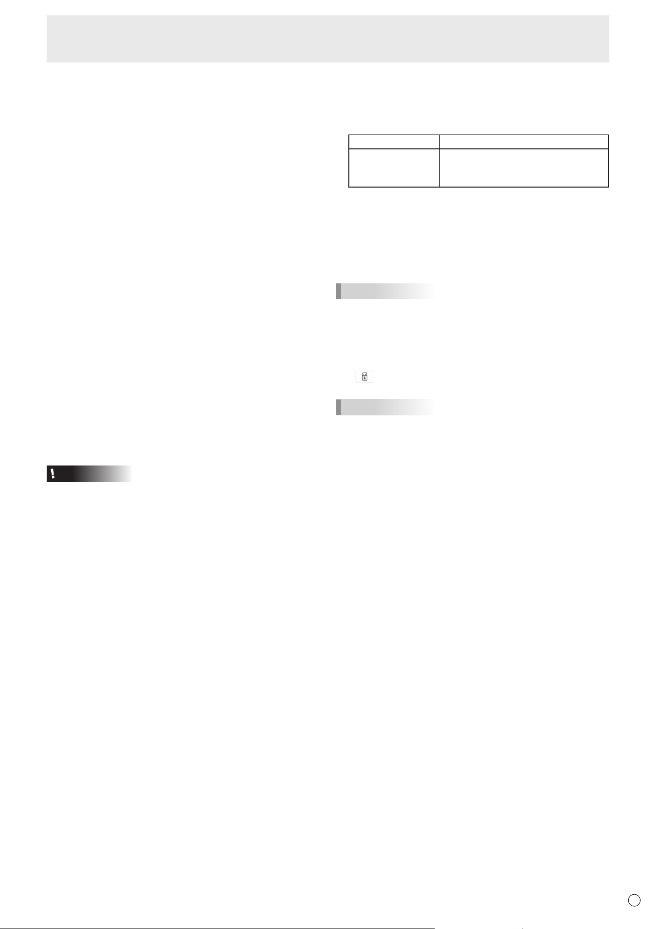
Supported USB flash drives
File System FAT32/NTFS (Read only)
Capacity
Up to 64 GB
(For FAT32, the maximum file size is
4 GB)
• A USB flash drive that is encrypted or has a security
function cannot be used.
• Use a USB flash drive with a shape that can be inserted in
the USB port. Some USB flash drives with special shapes
cannot be inserted. Do not forcibly insert a USB flash drive.
This may damage the connector or cause failure.
TIPS
• You can prohibit the use of USB flash drive. (See page 46.)
n
How to remove a USB flash drive
1. Start “File Explorer”. (See page 38.)
2. Select the USB flash drive to remove, and then touch
.
TIPS
• To remove a USB flash drive connected to a computer,
refer to the manual of the computer.
14
E
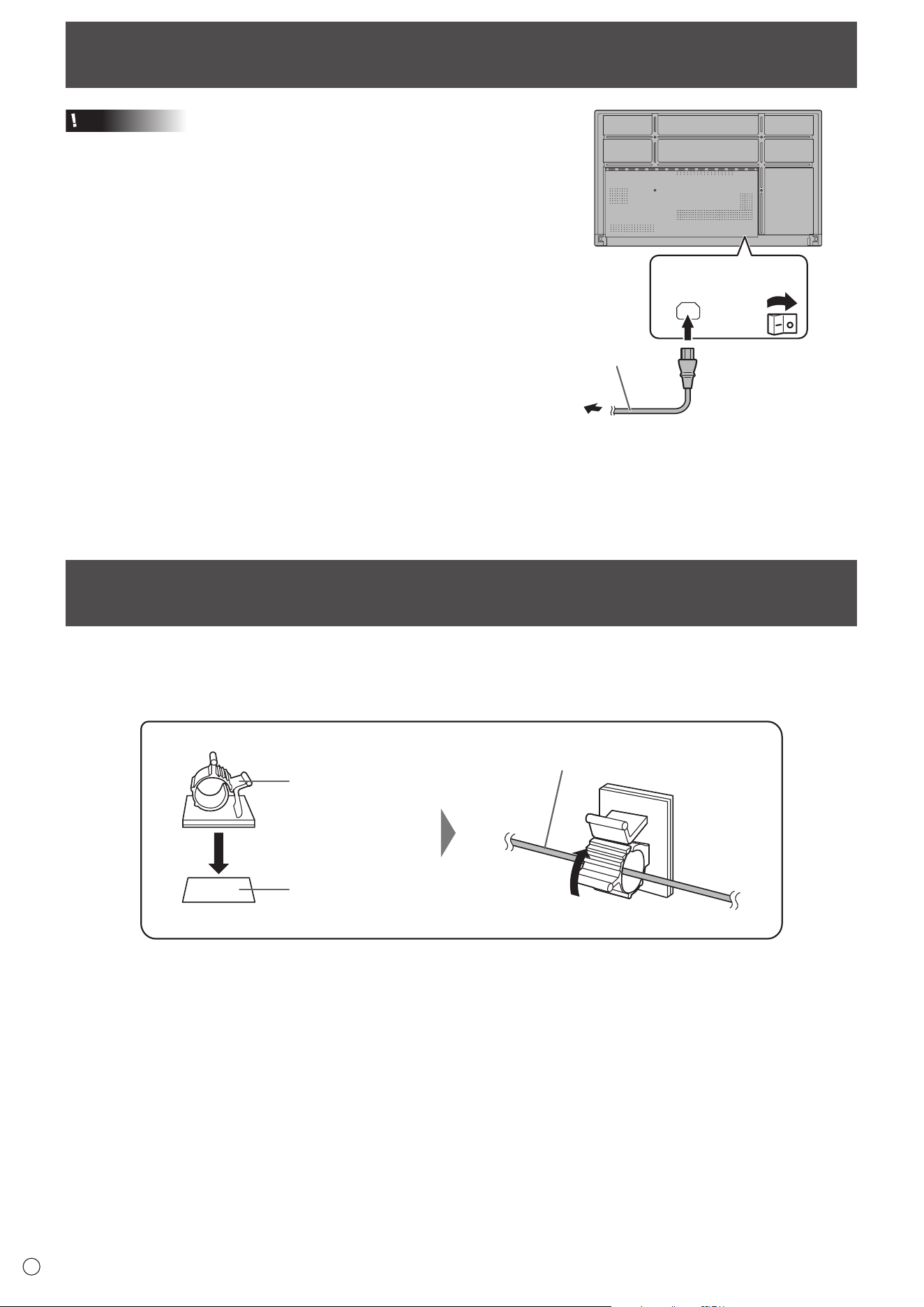
Connecting the Power Cord
Caution
• Use only the power cord supplied with the monitor.
1. Turn off the main power switch.
2. Plug the power cord (supplied) into the AC input
terminal.
3. Plug the power cord (supplied) into the power outlet.
Main power
switch
AC input
terminal
For power
outlet
3
Power cord (Supplied)
21
Binding Cables
The supplied cable clamps can be used to clamp the power cord and cables connected to the back of the monitor.
Attach the supplied cable clamps to a flat surface, removing any dust or dirt before attaching.
Do not attach over a vent.
Cable clamp
Affixing point
Cable
15
E
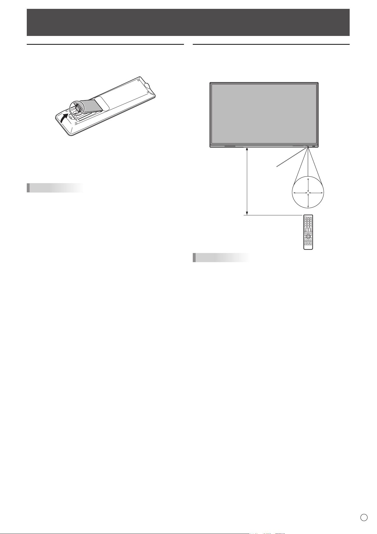
Preparing the Remote Control Unit
Remote control operation range
The operation range of the remote control unit is approx. 16.4
feet (5 m) at an angle of approx 10° from the center to the top/
bottom/right/left of the remote control sensor.
10°
10
°
10°
10°
16.4
feet
(5 m)
Remote
control sensor
TIPS
• Do not expose the remote control unit to shock by dropping
or stepping on it. This could lead to a malfunction.
• Do not expose the remote control unit to liquids, and do not
place it in an area with high humidity.
• The remote control unit may not work properly if the remote
control sensor is under direct sunlight or strong lighting.
• Objects between the remote control unit and the remote
control sensor may prevent proper operation.
• Replace the batteries when they run low as this may
shorten the remote control’s operation range.
• If a fluorescent light is illuminated near the remote control
unit, it may interfere with proper operation.
• Do not use it with the remote control of other equipment
such as air conditioner, stereo components, etc.
Installing the batteries
1. Placeyourfingeronthepartmarkedwiththe▲,and
then pull the cover off.
2. See the instructions in the compartment and put in the
batteries (R03 or LR03 (“AAA” size) x 2) with their plus
(+) and minus (-) sides oriented correctly.
3. Close the cover.
TIPS
• When the batteries become exhausted, replace them with
new (commercially available) batteries.
• The supplied batteries may become exhausted quickly
depending on how they are stored.
• If you will not be using the remote control for a long time,
remove the batteries.
• Use manganese or alkaline batteries only.
16
E
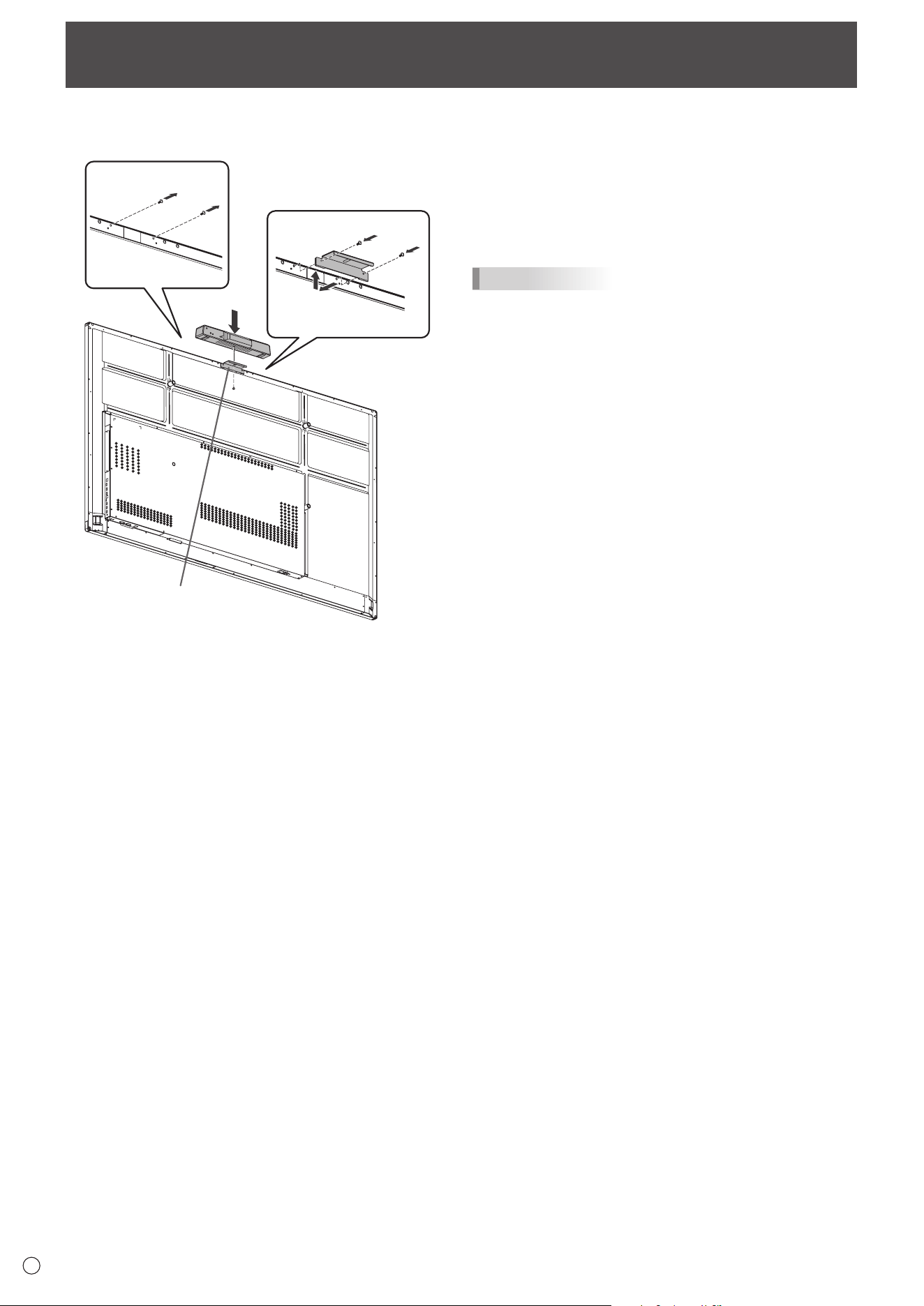
Mounting a web camera
1
2
3
Camera mount
It is possible to mount the PN-ZCMS1 Video-Conferencing Soundbar (optional) or a commercially available web camera.
1. Remove the screws from this monitor.
2. Attach the camera mount (supplied) with the camera
mount screw (M3 x 10) (supplied) (x2).
3. Attach the web camera on the camera mount with the
camera screw (inch thread) (supplied) (x1).
TIPS
• Store the removed screws.
After removing the camera mount, put back the removed
screws.
17
E
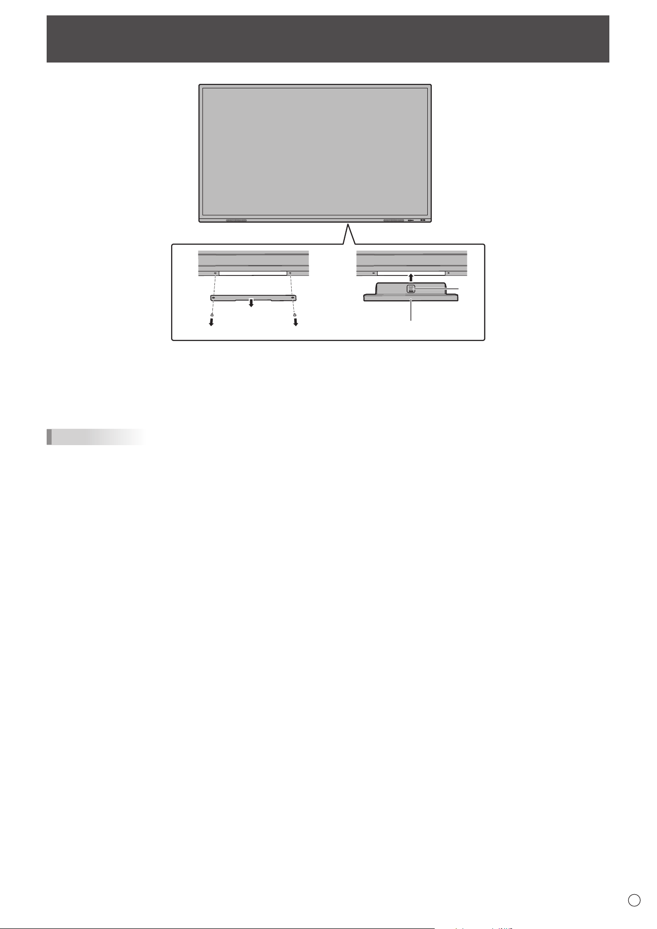
Attaching the wireless adapter
1 2
Wireless adapter
*
1. Remove the bottom cover.
2. Attach a wireless adapter.
Take note of the direction of the wireless adapter.
The surface with the * mark is the front.
TIPS
• Store the removed cover and screws.
After removing the wireless adapter, put back the cover, and fasten it with the removed screws.
18
E
Caution
• Turn on the monitor first before turning on the computer or
playback device.
• When switching the main power switch or the POWER
button off and back on, always wait for at least 5 seconds.
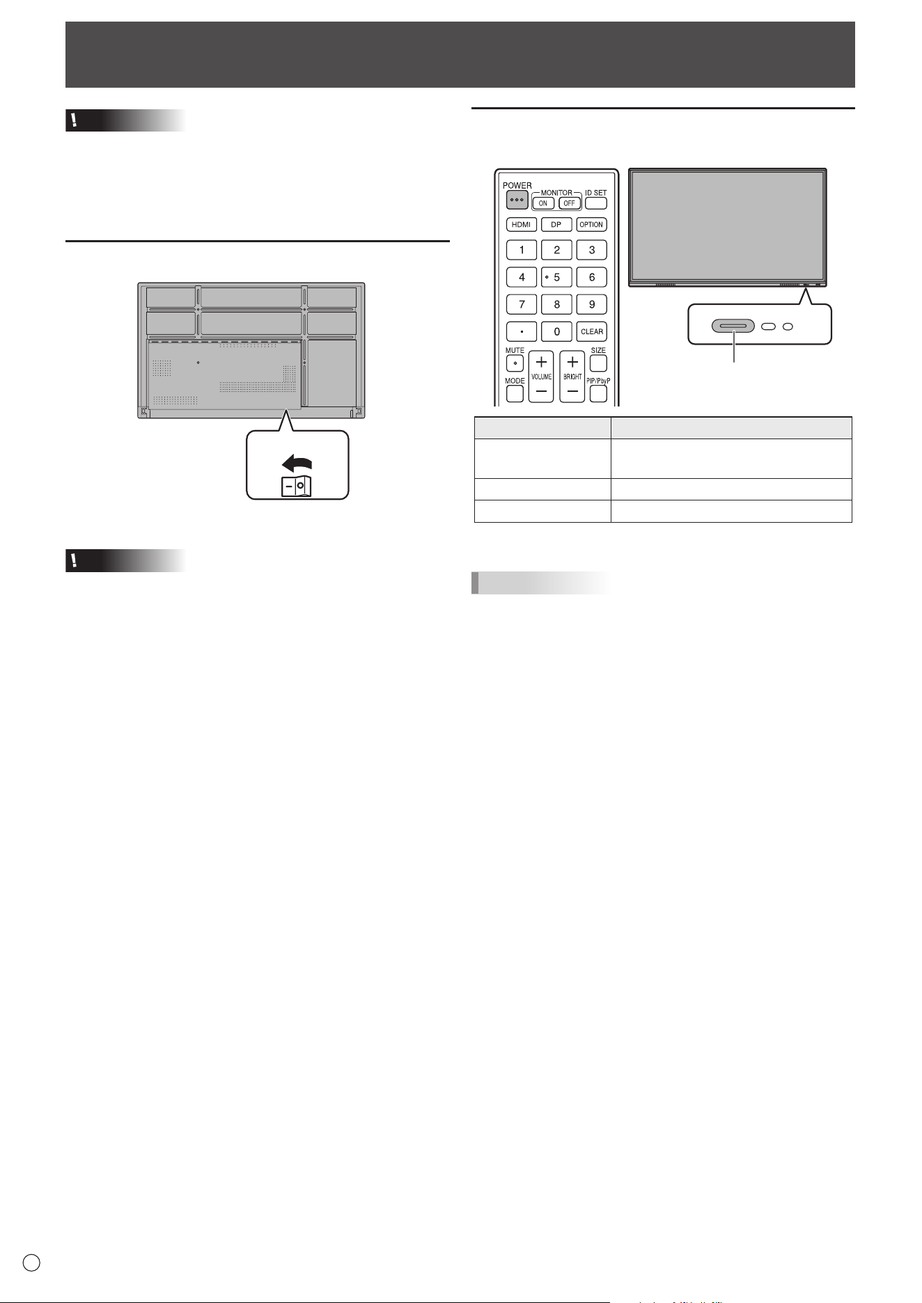
A short interval may result in a malfunction.
Turning on the main power
Main power switch
Off mode, when main power is off.
Caution
• The main power must be turned on/off with the main power
switch. Do not connect/disconnect the power cord or turn
the breaker on/off while the main power switch is on.
• For a complete electrical disconnection, pull out the main
plug.
Turning Power On/Off
Turning power on
1. Press the POWER button.
POWER button / Power LED
Status Status of the monitor
Blue lit
Power on
Sleep state (Backlight off)
Orange lit Power off (Standby state*)
Blue flashing Input signal waiting state
* Standby mode when “Power Save Mode” is set to on.
TIPS
• When the main power switch is off, the monitor cannot be
turned on.
• If the monitor is in the input signal waiting state and you
perform the operation described below, the monitor enters
standby state.
- Press the POWER button on the remote control unit.
- Press and hold the POWER button on the monitor.
• To disable the logo screen from displaying when turning the
power on, set “Logo Screen” to off on the Setup menu.
• You can fix the input mode that appears after startup. Set
“Start Input Mode” of “Startup & Shutdown” on the System
menu. (See page 48.)
19
E
Turning Power On/Off
n
Operations after first power-on
When you turn on the power for the first time, the language
settings screen appears.
1. Select a language, and then touch “Next”.
The “Date & Time Settings” screen appears.
2. Set the date and time, and then touch “Next”.
The power save mode settings screen appears.
3. Configure the settings according to the screen.
YES:
• “Power Save Mode” is set to on.
• Current consumption is reduced while the monitor is in
standby state. Android is also shut down. Note, however,
that the startup time from standby state becomes longer.
NO:
• “Power Save Mode” is set to off.
• Startup time from standby state is reduced. Note,
however, that more power will be consumed in standby
state. Android continues to run in standby state.
Even after being set, you can change the “Power Save
Mode”. (See page 46.)
4. When a screen indicating that the settings are complete
appears, touch “Finish”.
The home screen of APPLICATION mode appears.
(See page 22.)
TIPS
The clock stops if the main power remains off for about 3
days.*
(*Approximate time. The actual time varies depending on the
state of the monitor.)
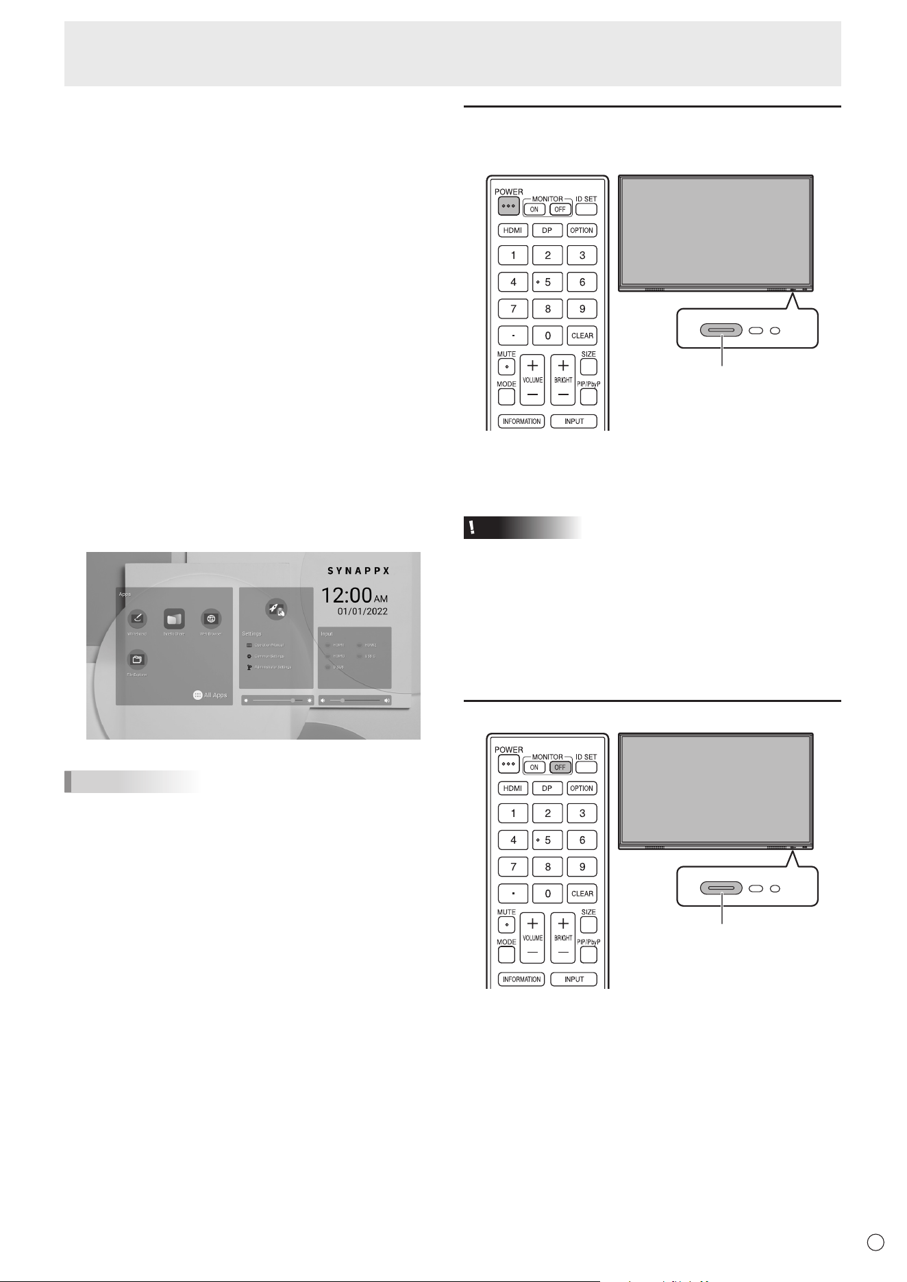
Turning power off
1. Press the POWER button on the remote control unit.
Or, press and hold the POWER button on the monitor.
POWER button
A confirmation screen appears.
2. Select “OK”.
The power will turn off. (Standby state)
Caution
• When the power is turned off, the application data that is
not saved is lost.
• A message is displayed before the power turns off. Save
any data you need.
• If the monitor will be turned off by schedule, “Off if No
Operation” or RS-232C control, save any data you need in
advance. The power will turn off even if there is unsaved
data. (The data will be lost.)
Sleep (Backlight off)
POWER button
1. Press the MONITOR OFF button on the remote control
unit.
Or, press the POWER button on the monitor.
The backlight will turn off.
The previous state can be restored by touching the screen or
pressing any button (excluding MONITOR OFF, PIP/PbyP).
20
E
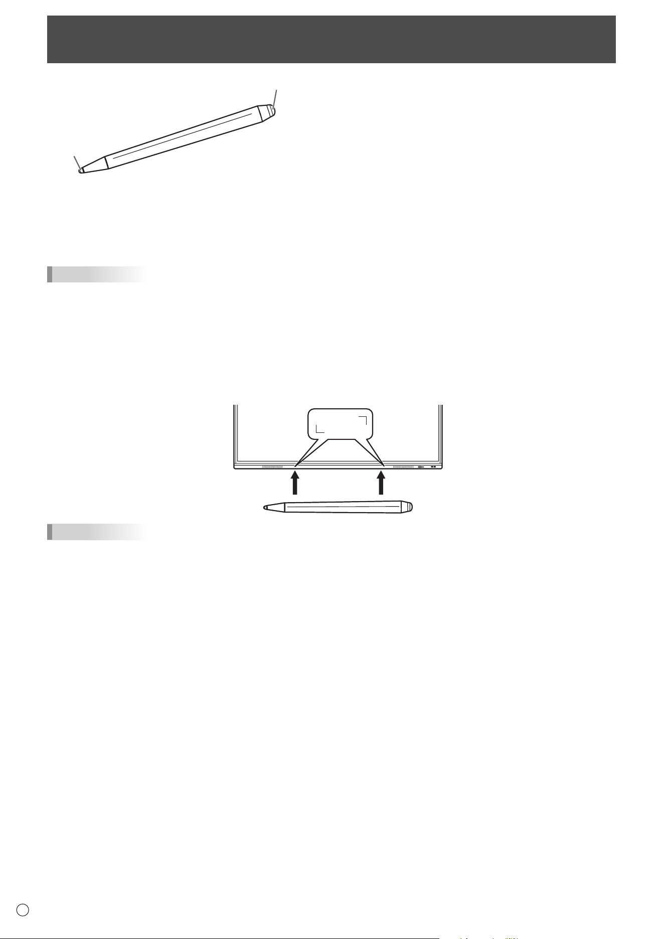
Touch Pen
Pen tip (thin)
Pen tip (thick)
The following software recognizes the side of the touch pen that is touching the screen, enabling the two sides to be used as
different pens.
• Whiteboard
For details on how to use the touch pen in Whiteboard, refer to “Whiteboard” (see page 29).
TIPS
• In the case of an Overlay board (See page 27.), multiple touch pens can be used simultaneously. In other cases, multiple
touch pens cannot be used simultaneously.
• When multiple touch pens are used on an Overlay board (See page 27.), lines may break.
- When touched simultaneously.
- When touch pens are moved near each other.
• If the pen tip becomes worn or damaged, replace the touch pen. To purchase a new touch pen, consult your dealer.
The supplied touch pen is attached to this monitor.
TIPS
• Do not attach anything other than the supplied touch pen.
• Magnet is used to attach the supplied touch pen. Do not move close watch or magnetic card to it.

21
E
Touch action
Touch action
Touch actions that can be used with this monitor differ
according to operating system and application. The functions
of touch actions are also different. For details, check operating
system Help and the application’s support documentation.
TIPS
• On the Mac, the actions are the equivalent mouse actions.
• For the procedures for using the touch pen in the Pen
Software, see the Pen Software Operation Manual.
•
The screen may not respond correctly in the following cases:
- Touch gesture is too quick.
- The distance between the two points is too short.
- The two points intersect.
• In Windows 8.1/10, input panel functions can be used.
For details, see Windows Help.
Input panel: A software keyboard and an input panel with
handwriting recognition appear on the screen.
• In Windows 8.1/10, the ink function of Microsoft Office
can be used. Handwritten comments can be written, and
handwriting can be recognized.
For details, see Microsoft Office Help.
Cautionary points
• Do not use the touch pen for any purpose other than touch
panel operation.
• Do not press hard on the pen tip.
• Operation will not take place correctly if there is an obstacle
between the infrared transmitter/receiver and the touch pen
or your finger. Operation will not take place correctly if your
fingers or your sleeve is near the screen.
• If the touch pen is held too flat against the screen, the touch
position may not be correctly detected.
• If the touch pen does not work at the edge of the screen,
move it slowly.
• This may not operate correctly if there is an inverter
fluorescent light nearby.
• If there is dirt or foreign matter on the tip of the touch pen,
remove it. Foreign matter may damage the screen.
• The touch pen position may occasionally deviate in the
login screen. In this case, use the keyboard or mouse.
• If the USB cable becomes disconnected, the touch
panel may not operate correctly after the USB cable is
reconnected. In this case, restart the computer.
• When removing the pen tip or your finger from the screen,
remove a sufficient distance. If the distance is not sufficient,
a touch may be detected even if the screen is not touched.
22
E
Basic Operation
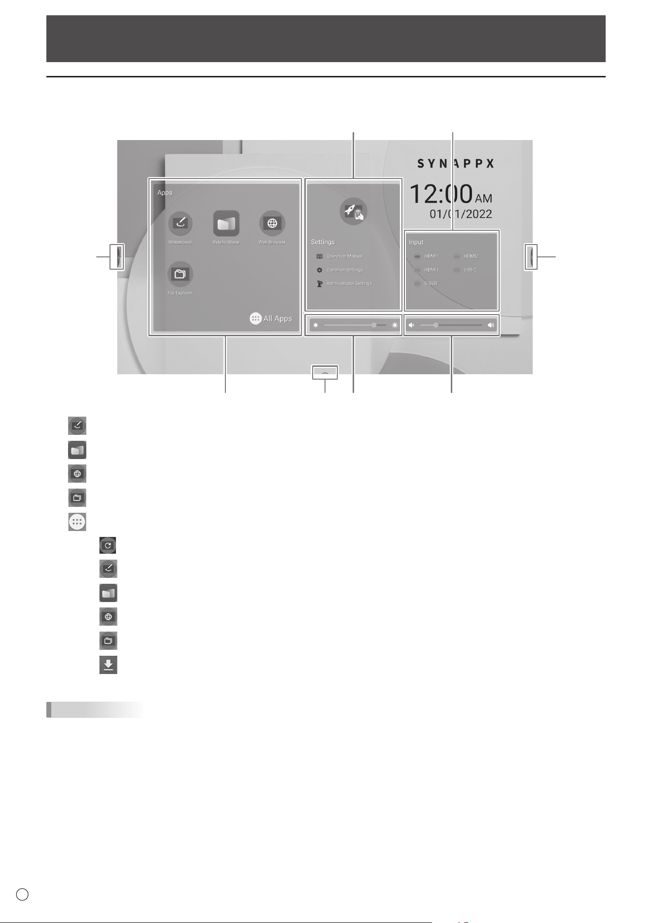
About the home screen of APPLICATION mode
This appears when the input mode is changed to APPLICATION.
(3)
(6) (5)
(4)(1)
(2)
(2)
(2)
(1) Start “Whiteboard”. (See page 29.)
Start “Bytello Share”. (See page 35.)
Start “Web Browser”. (See page 40.)
Start “File Explorer”. (See page 38.)
Display the list of applications.
Display “Updater”. (See page 41.)
Start “Whiteboard”. (See page 29.)
Start “Bytello Share”. (See page 35.)
Start “Web Browser”. (See page 40.)
Start “File Explorer”. (See page 38.)
Confirm the downloaded file.
TIPS
• When a confirmation screen to allow access appears when the application is started for the first time, select “Allow”.
23
E
Basic Operation
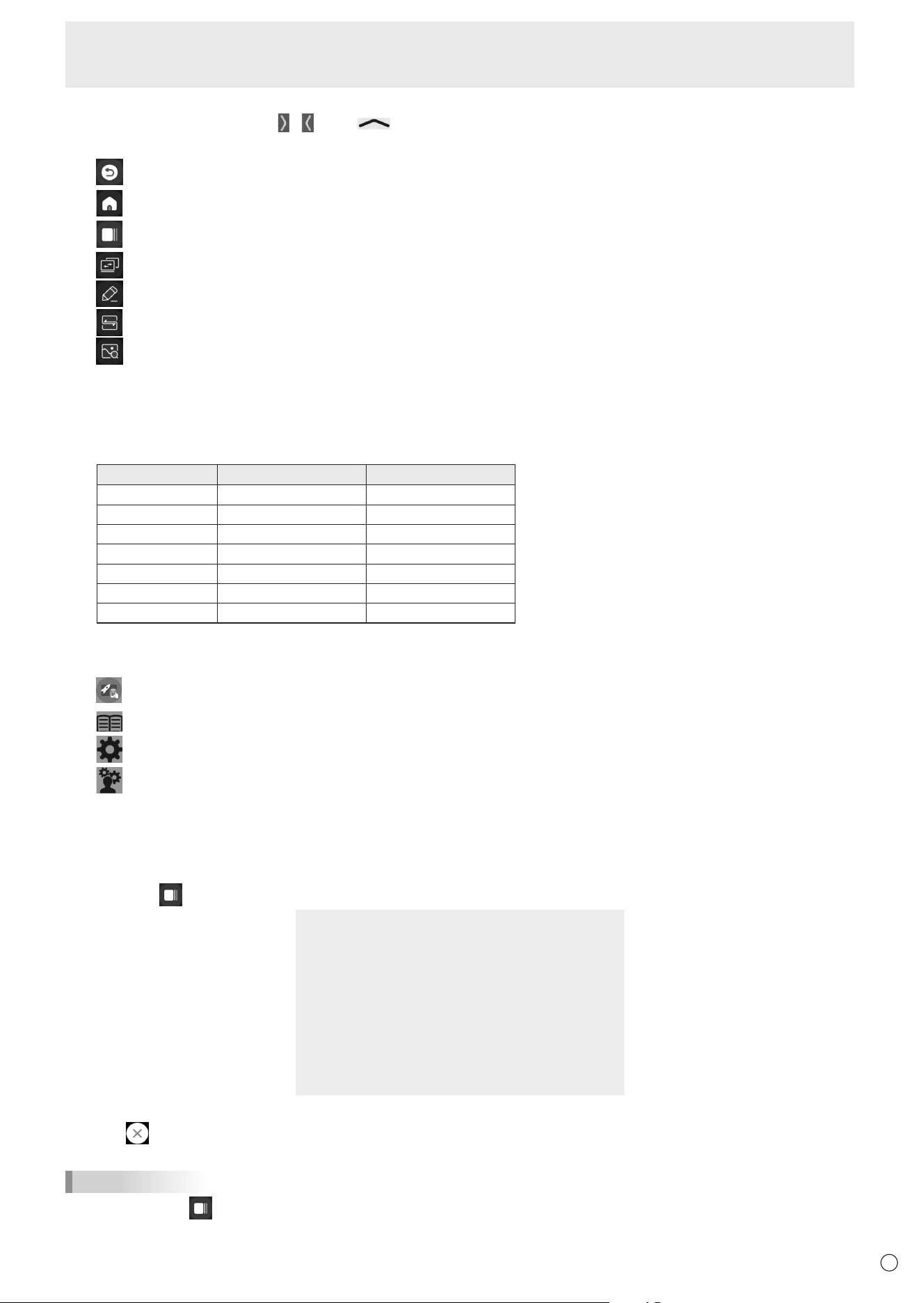
(2)
When you touch the screen, “
” “ ”, and “ ” appear.
Touch to view the toolbar.
Go back to previous screen.*
Return to home screen of APPLICATION mode.
Display a preview of the application being executed and the last external input. (See below.) *
Display “Input” menu. (See page 25.)
Start “Overlay board”. (See page 27.)
Start “Bytello Share”. (See page 35.)
Display the images being shown on the monitor as stills. (See page 28.)
* Displayed when the input mode is APPLICATION mode.
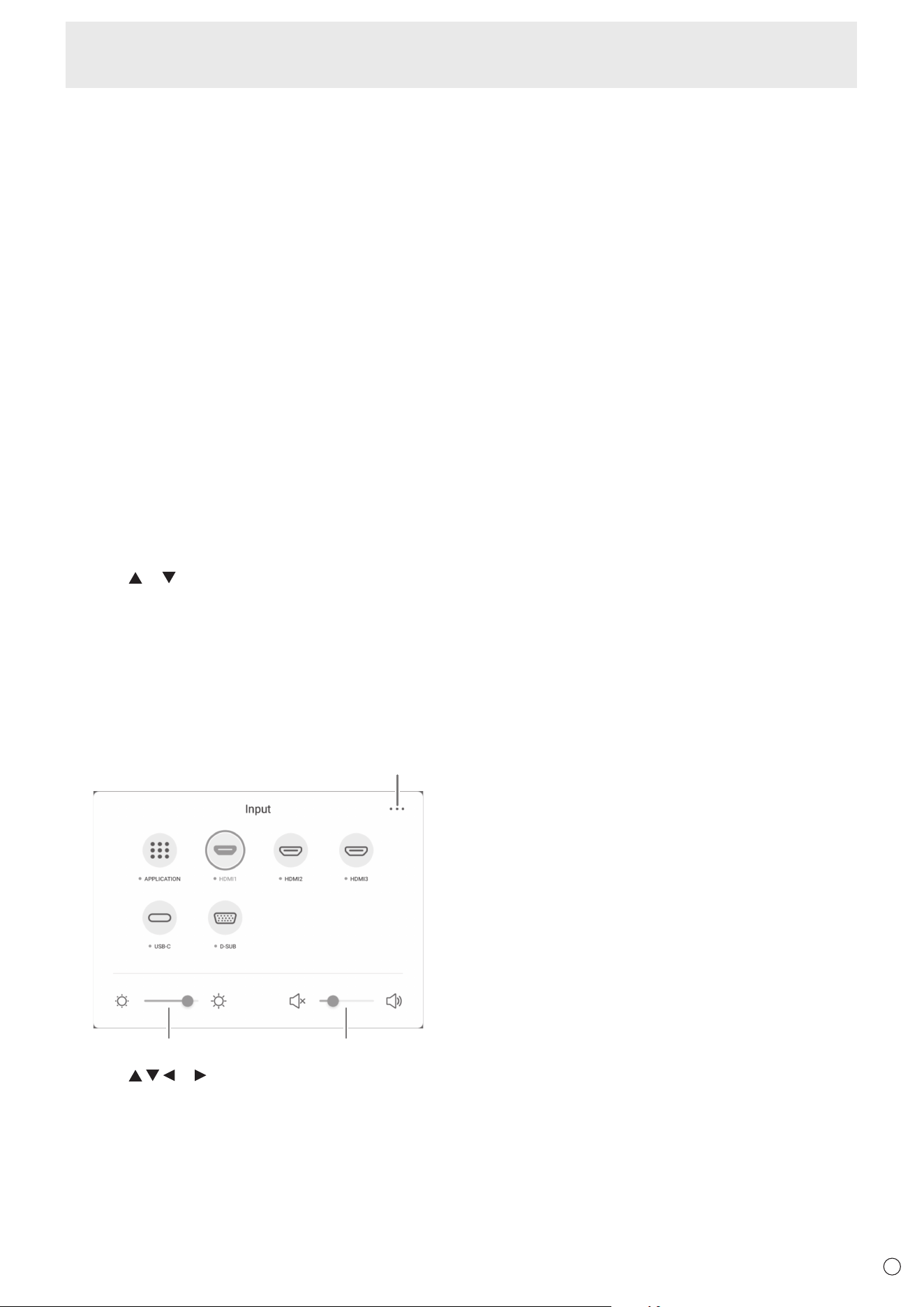
(3) Adjust the brightness.
(4) Adjust the volume.
(5) Change the input mode.
Input mode Video Audio
APPLICATION APPLICATION APPLICATION
HDMI1 HDMI1 input terminal HDMI1 input terminal
HDMI2 HDMI2 input terminal HDMI2 input terminal
HDMI3 HDMI3 input terminal HDMI3 input terminal
D-SUB D-sub input terminal Audio input terminal
USB-C USB Type C port USB Type C port
OPS Expansion slot Expansion slot
The icon of the terminal that is not connected is grayed out.
(6) Display the manual of this monitor and make various settings.
Switch the input mode to a computer on which “Synappx” is installed. *
Display the manual of this monitor.
Display the “Common Settings” menu. (See page 42.)
Display the “Administrator Settings” menu. (See page 45.)
* Set which input mode to switch in “Synappx Settings” on the Setup menu.
Synappx applications work with your current office technology to bring smart home convenience into the workplace.
Have a smooth meeting. Share or print information right where it’s needed. For details on Synappx, see the Synappx manual.
n
List display of startup applications (recent app bars)
When you touch on the toolbar in APPLICATION mode, a preview of the application being executed and the last external input is displayed.
• When you touch the preview, the display switches to that application.
• Touch
to exit the application.
• Touch “Clean All” to exit all applications.
TIPS
• When you touch on the toolbar displayed on the side, the recent app bar is displayed on the side.
• A preview of the whiteboard is not displayed.
24
E
Basic Operation
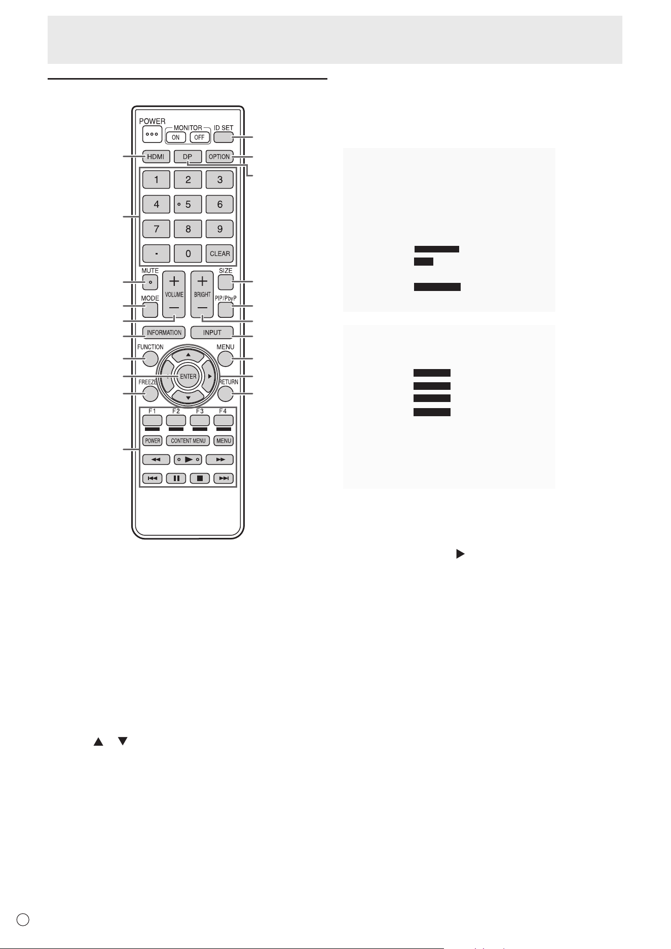
Using the remote control unit
1
2
3
4
5
6
7
8
9
10
11
12
13
14
15
16
17
18
19
20
1. HDMI
Switch the input mode to HDMI1, HDMI2 or HDMI3.
2. Numeric input buttons
These buttons are used for setting such as LAN setting.
3. MUTE
Turns off the volume temporarily.
Press the MUTE button again to turn the sound back to the
previous level.
4. MODE (Color mode selection)
In video input mode (other than “APPLICATION”), the color
mode changes.
The menu is displayed.
Press the
or button to select the color mode.
• High Illuminance is a display with colors suited to bright
locations.
5. VOLUME +/- (Volume adjustment)
Press + or - to adjust the volume.
6. INFORMATION
Displays monitor information.
X.X.X
XXXXXXXX
XXXX-XXXXXX-XX-XXXX
XXXXXXXX
XXX.XXX.XXX.XXX
XXX.XXX.XXX.XXX
XXX.XXX.XXX.XXX
XX:XX:XX:XX:XX:XX
Thedisplaychangesfrom“Information1”→“Information2”→
clear display, and so on every time you press this button.
When displaying “Information”, the display changes from
“Information1”→“Information2”→“Information1”,andsoon
every time you press the
button.
Pressing the RETURN button disappears the display.
• The display disappears automatically after about 15
seconds.
7. FUNCTION
Use this to display the FUNCTION menu. (See page 50.)
8. ENTER
Confirms the setting.
9. FREEZE
Freezes the video shown on the monitor. (See page 28.)
In some cases a residual image may occur. Do not freeze the
video for a long time.
25
E
Basic Operation
10. Buttons for operating the HDMI-connected device
If “HDMI CEC Link” is set to on, you can operate devices that
support HDMI CEC when the input mode is HDMI1.
CONTENT MENU button
• When input mode is APPLICATION
- The home screen of APPLICATION mode appears.
• When “HDMI CEC Link” is set to on and input mode is
HDMI1
- Operate devices that support HDMI CEC.
• When “HDMI CEC Link” is set to off and input mode is
other than APPLICATION
- The input mode changes to APPLICATION.
11. ID SET
This is not used with this monitor.
12. OPTION
Switch the input mode to APPLICATION or OPS.
13. DP (DisplayPort)
Switch the input mode to USB-C.
14. SIZE (Screen size selection)
In video input mode (other than APPLICATION), the screen
size changes.
The menu is displayed.
Press the
or button to select the screen size. (See page
26.)
15. PIP/PbyP
This is not used with this monitor.
16. BRIGHT +/- (Brightness adjustment)
Press + or - to adjust the brightness.
17. INPUT (Input mode selection)
The menu is displayed.
(2) (3)
(1)
Press the or button to select the input mode, and
press the ENTER button to enter.
* For the input modes that can be selected, see “About the
home screen of APPLICATION mode” (see page 22).
(1) Displays the Common Settings menu screen.
(See page 42.)
(2) Adjust the brightness.
(3) Adjust the volume.
18. MENU
Displays the Common Settings menu screen. (See page 42.)
19. Cursor
These buttons are used to perform operations such as
selecting items, changing adjustment values, and moving the
cursor.
20. RETURN
Returns to the previous screen.
26
E
Basic Operation
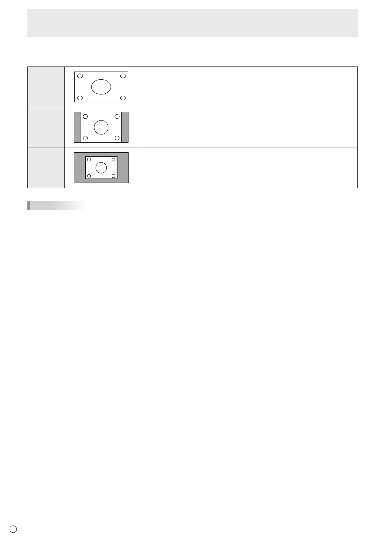
n
Switching the screen size
Even when the screen size is changed, the display may remain the same depending on the input signal.
Wide Displays image so it fills the entire screen.
Normal
Displays the image so it fills the screen without changing the aspect ratio.
Dot by Dot
Displays the dots of the input signals as the corresponding dots on the screen.
TIPS
• Using this monitor’s screen-size switching function to compress or expand the screen for commercial or public viewing in
establishments like cafes or hotels may infringe on the rights of the creators, as protected by Copyright Law, so please be
careful.
• The appearance of the original video may change if you select a screen size with a different aspect ratio than the original
image (e.g. TV broadcast or video input from external equipment).
• When 4:3 video is viewed with the whole screen using the screen-size switching function of this monitor, the edge of the video
may be lost or appear distorted. If you wish to respect the creator’s intentions, set the screen size to “Normal”.
• When playing commercial software, parts of the image (like subtitles) may be cropped. In this case select the optimal screen
size using the screen-size switching function of this monitor. With some software, there may be noise or distortion at the
edges of the screen. This is due to the characteristics of the software, and is not a malfunction.
• Depending on the original video size, black bands may remain at the edges of the screen.
27
E
Basic Operation
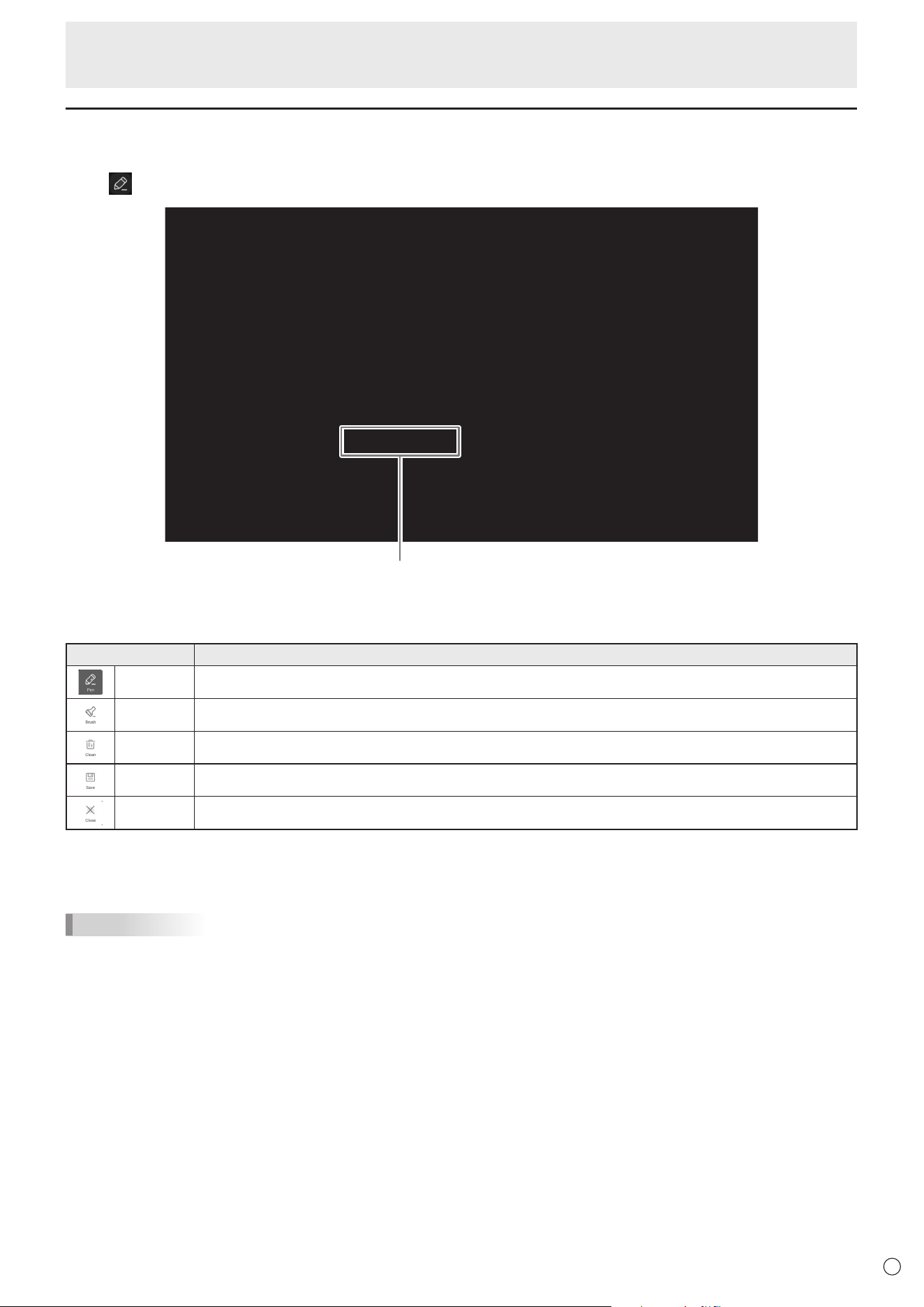
Overlay board (Mark)
You can draw characters or lines on the images being displayed on this monitor.
Touch
on the toolbar.
Operation bar
Tool Function
Pen
Draw a line. You can change the settings (color).
Brush
Draws a line without hiding objects under the line. You can change the settings (color).
Clean
Clear all the drawn lines.
Save
Save a board that is being drawn as an image. The image will be saved in the “Notes/Mark” folder.
Close
Exit the application.
You can erase an area of the screen that you touch with your palm.
Touch the screen with your palm, and when the cursor is appear, move your palm.
TIPS
• The operation bar can be moved by dragging.
• You cannot save a board in the USB flash drive.
After saving it in the internal storage, copy it to the USB flash drive with “File Explorer”.
• Cannot be saved when HDCP-compliant images input from the HDMI input terminal / USB Type-C port / OPS are being
displayed.
• You cannot add a sheet.
28
E
Basic Operation
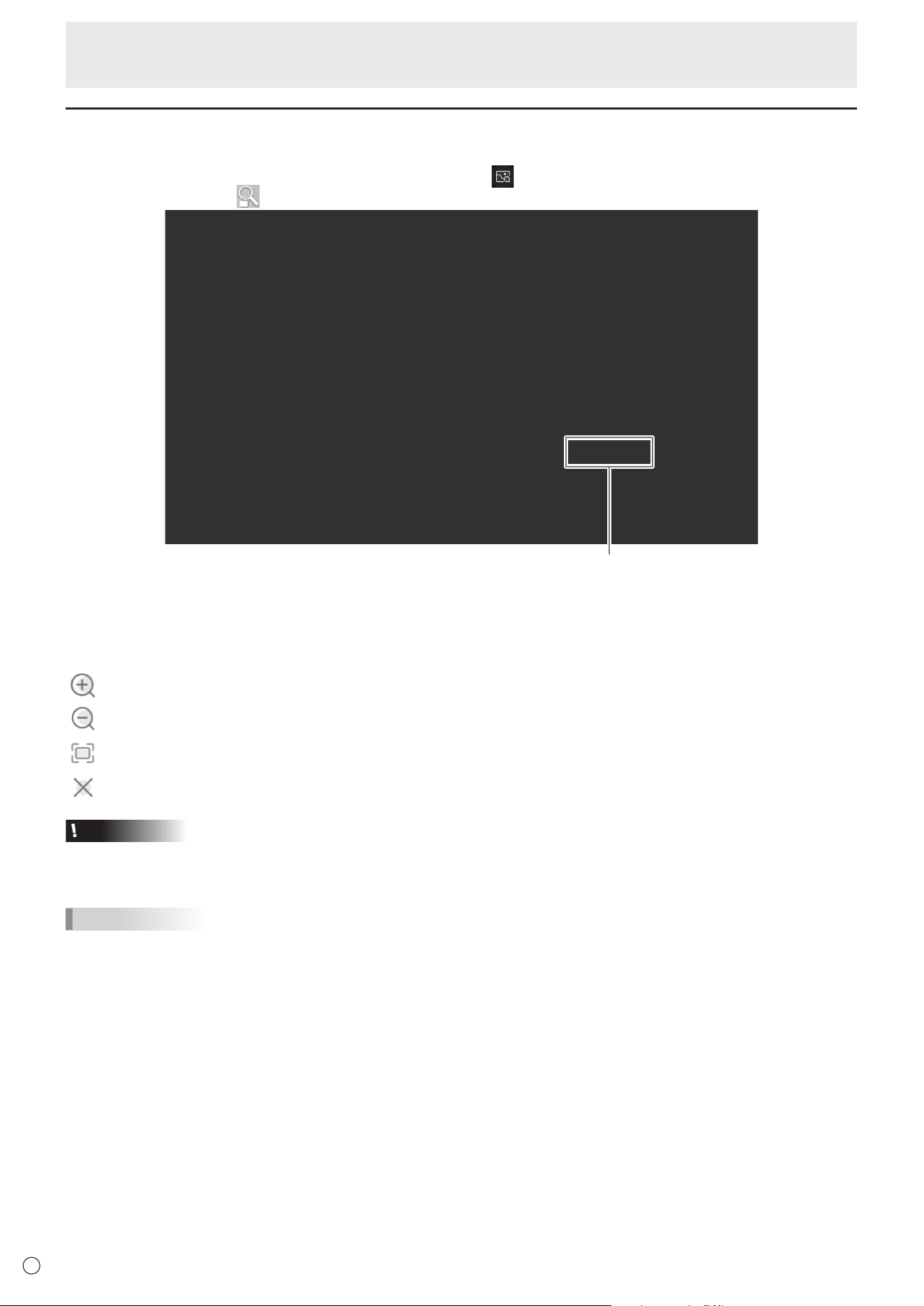
Freeze
Freezes the video shown on the monitor.
Either press the FREEZE button on the remote control unit, or touch
on the toolbar.
In the case of a still image,
is displayed at the top right of the screen.
Settings window
Settings window:
Touch to operate.
Magnify any location on the screen.
Reduce a magnified screen.
Display on full screen.
Cancel the still state.
Caution
• In some cases a residual image may occur. Do not freeze the video for a long time.
TIPS
• If you want to mute the audio from a still image, set “Mute with Freeze” on the Input & Output menu to on.
• To cancel, press any button other than the POWER button, MUTE button or VOLUME button on the remote control unit.
Freeze is also canceled when the input signal changes (switching to no signal, changing the resolution, etc.).

29
E
Whiteboard
• You can write letters or draw lines on the screen as a whiteboard.
• You can print or save content written on the screen.
• You can display an image or PDF file, and write/draw letters and lines on the image.
• In this application, the data of one screen is referred to as a “sheet”.
• A maximum of 10 sheets can be opened.
1. On the home screen of APPLICATION mode, touch “Whiteboard”.
Caution
• When the power is turned off, any data in Whiteboard is lost.
• A message is displayed before the power turns OFF. Save any data you need.
30
E
Whiteboard
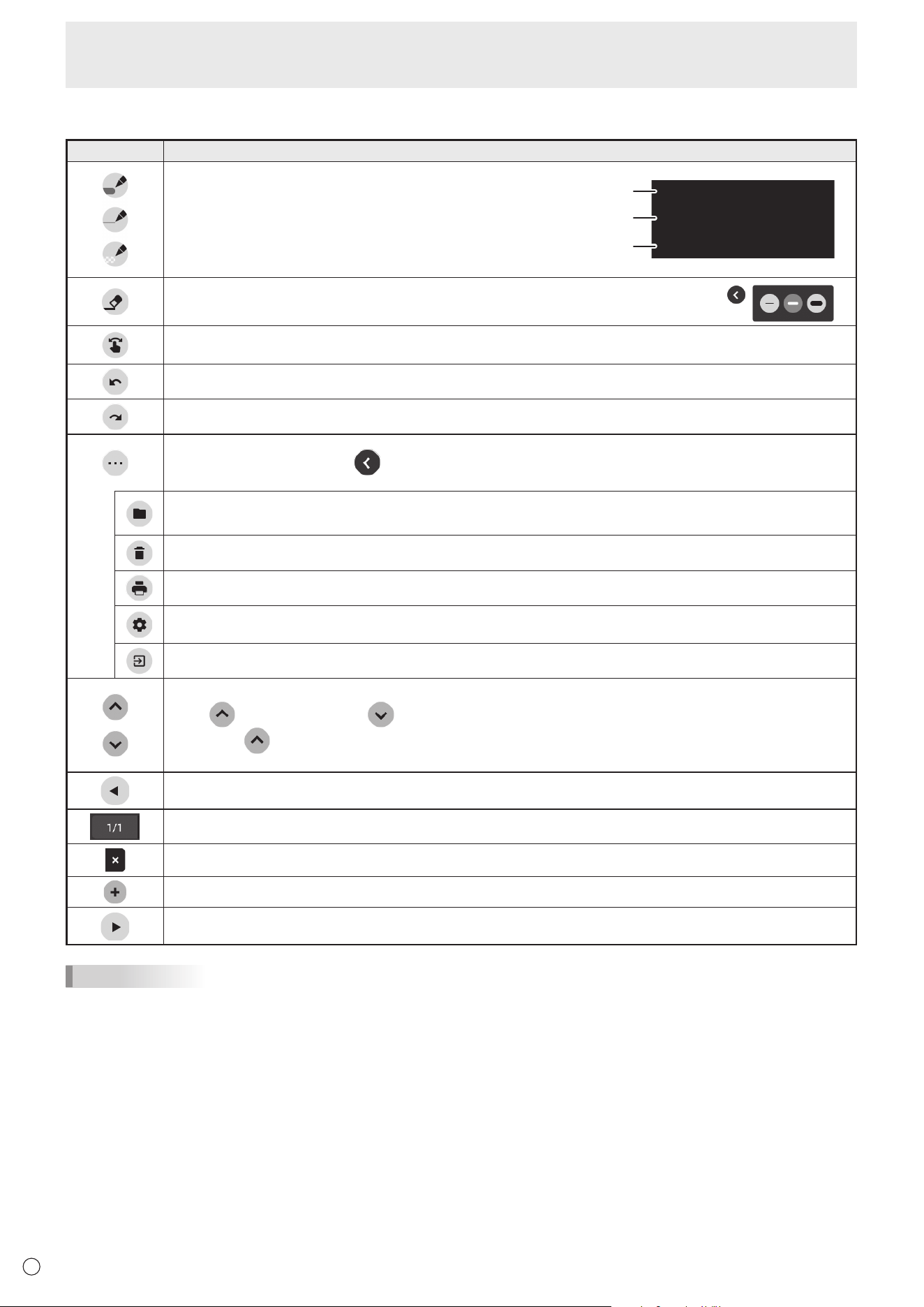
n
Function list
Tool Function
Draw lines. (See page 31.)
Pen palette
1
Pen palette
2
Pen palette
3
Erase a line that you drew. (See page 31.)
This appears when “Draw with pen and finger” is selected. (See page 34.)
Touch to perform gesture actions (enlarging/reducing, moving a sheet, etc.). (See page 32.)
Undo the previous drawing or edit. You can repeat undo a maximum of 50 times.
Redo an undone action.
The sub-menu will appear.
To close the sub-menu, touch
.
Save/open a sheet.
You can open an image or PDF file and use it as the background.
Delete a drawn line, opened image, or a sheet. (See page 33.)
Print a sheet.
Change the settings of this application. (See page 34.)
You can check the version of the application.
Exit this application.
Show/hide the tools.
Touch
to show the tools, or to hide the tools.
If you touch
on the opposite side when the tools appear, the displayed tools are hidden and the tools on
the opposite side are shown.
Display the previous sheet.
Shows the current sheet number and the total number of sheets.
Delete the currently displayed sheet.
Add a new sheet behind the currently displayed sheet.
Display the next sheet.
TIPS
• Multiple touch pens or fingers cannot be used simultaneously.
31
E
Whiteboard
Drawing
The line/eraser setting is assigned to each touch pen (thin/thick) and finger.
Operate with what you use to draw.
1. Touch one of “Pen palette 1” to “Pen palette 3”.
If the line you want to draw does not exist, touch one of “Pen palette 1” to “Pen palette 3” twice. You can change the line
setting (non-transparent/transparent, thickness, color).
2. Draw.
TIPS
• On the touch pen (supplied), you can set the thin tip and thick tip of the pen separately.
When this software is launched, the thin tip is set to “Pen palette 1”, and the thick tip is set to “Eraser”.
• To draw with only a touch pen, select “Draw only with pen”. (See page 34.)
To use your finger to draw, select “Draw with pen and finger”. (See page 34.)
• When this software is launched, drawing by finger is set to “Pen palette 1”.
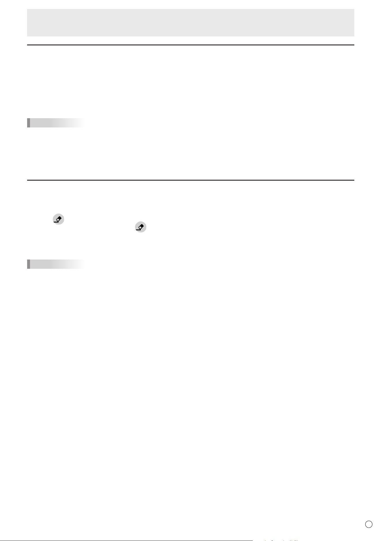
Erasing a drawn line
The line/eraser setting is assigned to each touch pen (thin/thick) and finger.
Operate with what you use to erase.
1. Touch
.
To change the size of the eraser, touch
twice.
2. Move while continuing to touch the place you want to erase.
The part you move over is erased.
TIPS
• On the touch pen (supplied), you can set the thin tip and thick tip of the pen separately.
When this software is launched, the thin tip is set to “Pen palette 1”, and the thick tip is set to “Eraser”.
• To use your finger to erase, select “Draw with pen and finger”. (See page 34.)
You can erase an area of the screen that you touch with your palm.
Touch the screen with your palm, and when the cursor is appear, move your palm.
32
E
Whiteboard
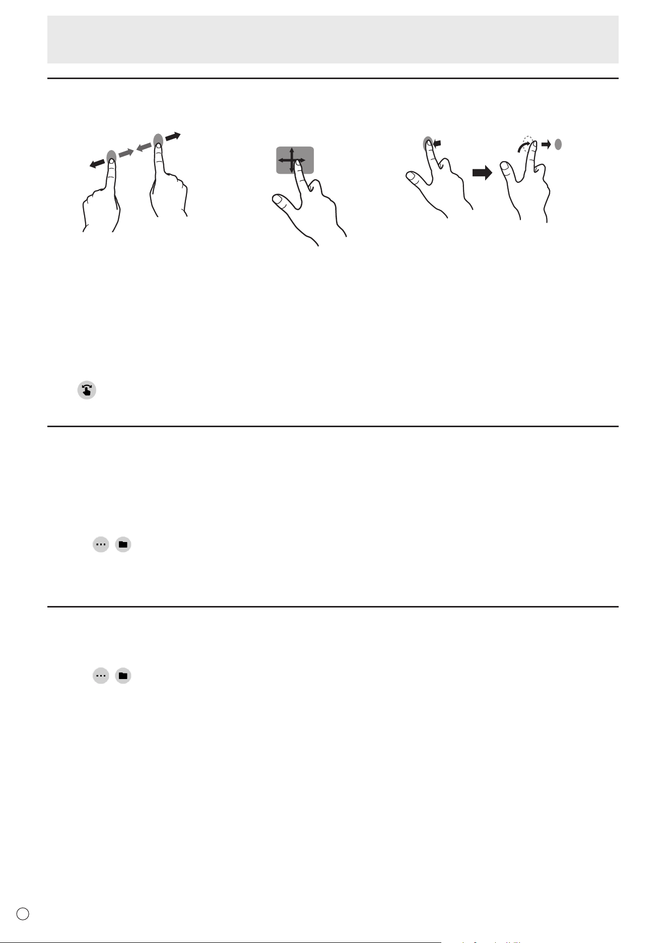
Actions using your finger (gesture)
Enlarge/reduce a sheet Moving the display position of a sheet
(when enlarged)
Move to the previous/next* sheet
Pinch-in/pinch-out Swipe Left/right flick
* Add a new sheet when the last sheet is being displayed. (Up to 10 sheets)
When drawing with a touch pen (supplied)
(When “Draw only with pen” is selected (See page 34.))
Your finger can only be used for a gesture action.
When drawing with your finger
(When “Draw with pen and finger” is selected (See page 34.))
Touch
to perform a gesture action.
Opening a PDF or image on the current sheet
You can open a file in PDF format or an image (in JPEG or PNG format) on the current sheet.
• If there are lines drawn on the sheet, the file will appear under the lines.
• An opened image will appear in the full screen without changing the aspect ratio.
• Up to the 10 pages of a PDF file can be opened.
When there are multiple pages, the pages will appear in order starting from the current sheet.
• Depending on memory usage and other factors, it may not be possible to open a file even if it is in a supported format.
1. Touch
, .
2. Touch “Insert a PDF or an image to background”.
3. Select the file.
Opening a file
Data of this application that is saved in dedicated format (SDSW format) is opened as a new sheet.
The current sheet closes.
1. Touch
, .
2. Touch “Open file”.
3. Touch “Open without saving”.
To save the current sheet, touch “Save” and perform the save procedure.
4. Select the file.
33
E
Whiteboard
Saving a sheet
You can save a sheet in dedicated SDSW format or PDF format.
You can save the sheet to this monitor’s built-in memory (internal memory) or to a USB flash drive.
TIPS
• When you save a sheet in SDSW format, you can open the sheet in this application and re-edit the sheet.
• When you save a sheet in PDF format, an opened image and drawn lines are all saved as a single image.
(The sheet cannot be re-edited using this application.)
• The date and time of saving are automatically set in the file name. (Example:180101_120000.sdsw / 180101_120000.pdf)
1. Touch
, .
2. Touch “Save” (SDSW format) or “Save as PDF”.
A dialog box appears to let you specify the save location.
3. Specify the file save location and the file name.
4. Touch “Save”.
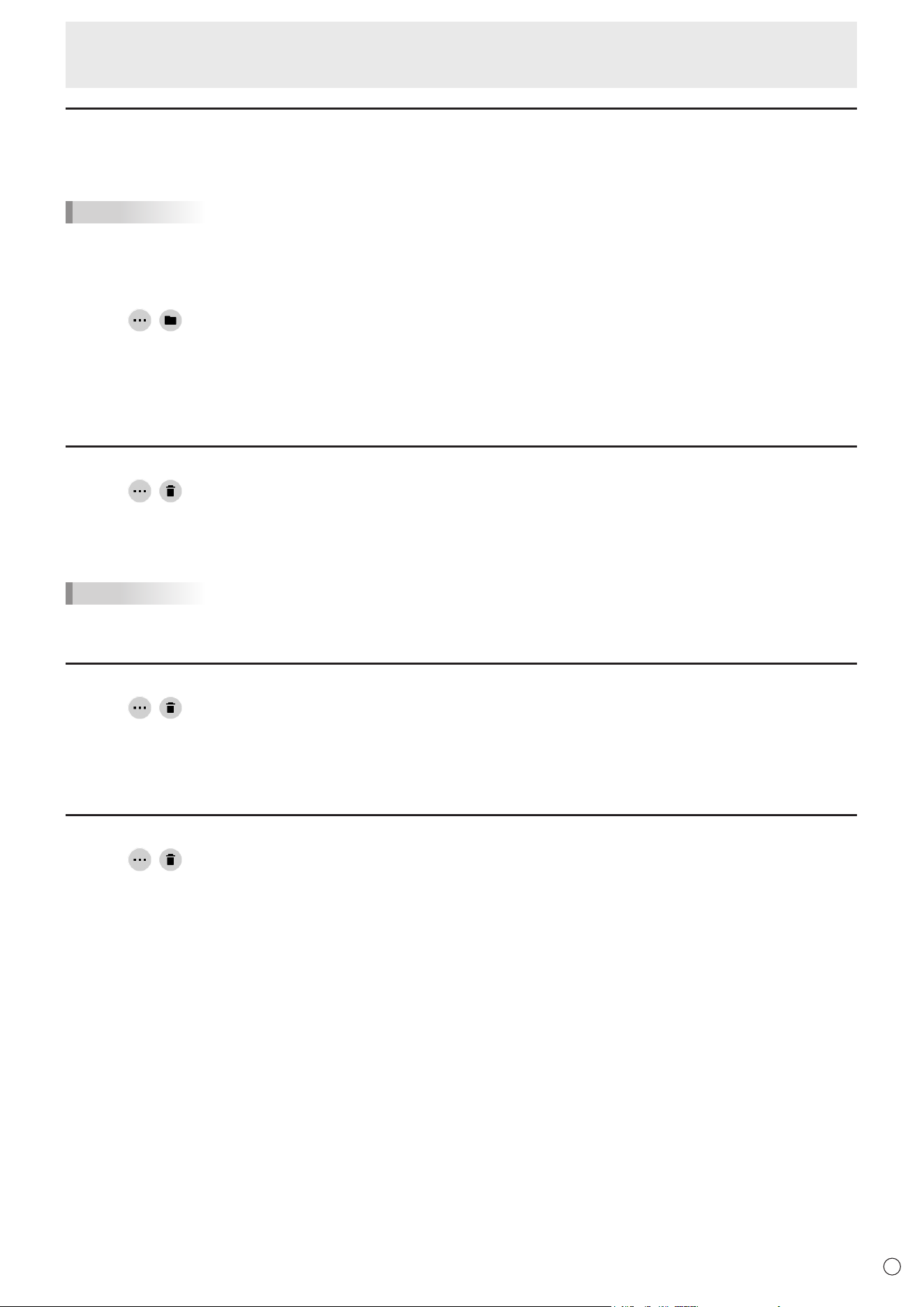
Erasing all lines drawn on the current sheet
1. Touch , .
2. Touch “Clear drawing data on Current sheet”.
A confirmation message will appear.
3. Touch “Yes”.
TIPS
• The sheet will not be deleted.
Clearing a PDF or an image opened on the current sheet
1. Touch , .
2. Touch “Clear background image on Current sheet”.
A confirmation message will appear.
3. Touch “Yes”.
Deleting a sheet
1. Touch , .
2. Touch “Delete Current sheet” or “Delete All sheets”.
A confirmation message will appear.
3. Touch “Yes”.
If you deleted all sheets, a new sheet will appear.
34
E
Whiteboard
Settings
n
Drawing with your finger (Draw with pen and finger) /
Drawing with only a touch pen (Draw only with pen)
1. Touch .
2. To draw with your finger: Touch “Draw with pen and finger”.
You can now draw with a touch pen and your finger.
Touch
before performing a gesture.
The button changes to “Draw only with pen”.
To draw with only a touch pen: Touch “Draw only with pen”.
You can now draw with only a touch pen.
Finger actions will now be gestures.
The button changes to “Draw with pen and finger”.
n
Returning the settings to their default state (Back to default settings)
1. Touch .
2. Touch “Back to default settings”.
3. When a confirmation message appears, touch “Yes”.
n
Checking the version of this software (Version Information)
1. Touch .
2. Touch “Version Information”.
3. When you have finished checking, touch “OK”.
35
E
Bytello Share
• You can display the image of another device on the same network on this monitor.
• Connections to all devices is not guaranteed.
• If the display is delayed, reduce the connected devices.
• “Bytello Share” is an application of Guangzhou Shirui Electronics Technology Co., Ltd. Functions may change due to updates
by Guangzhou Shirui Electronics Technology Co., Ltd.
n
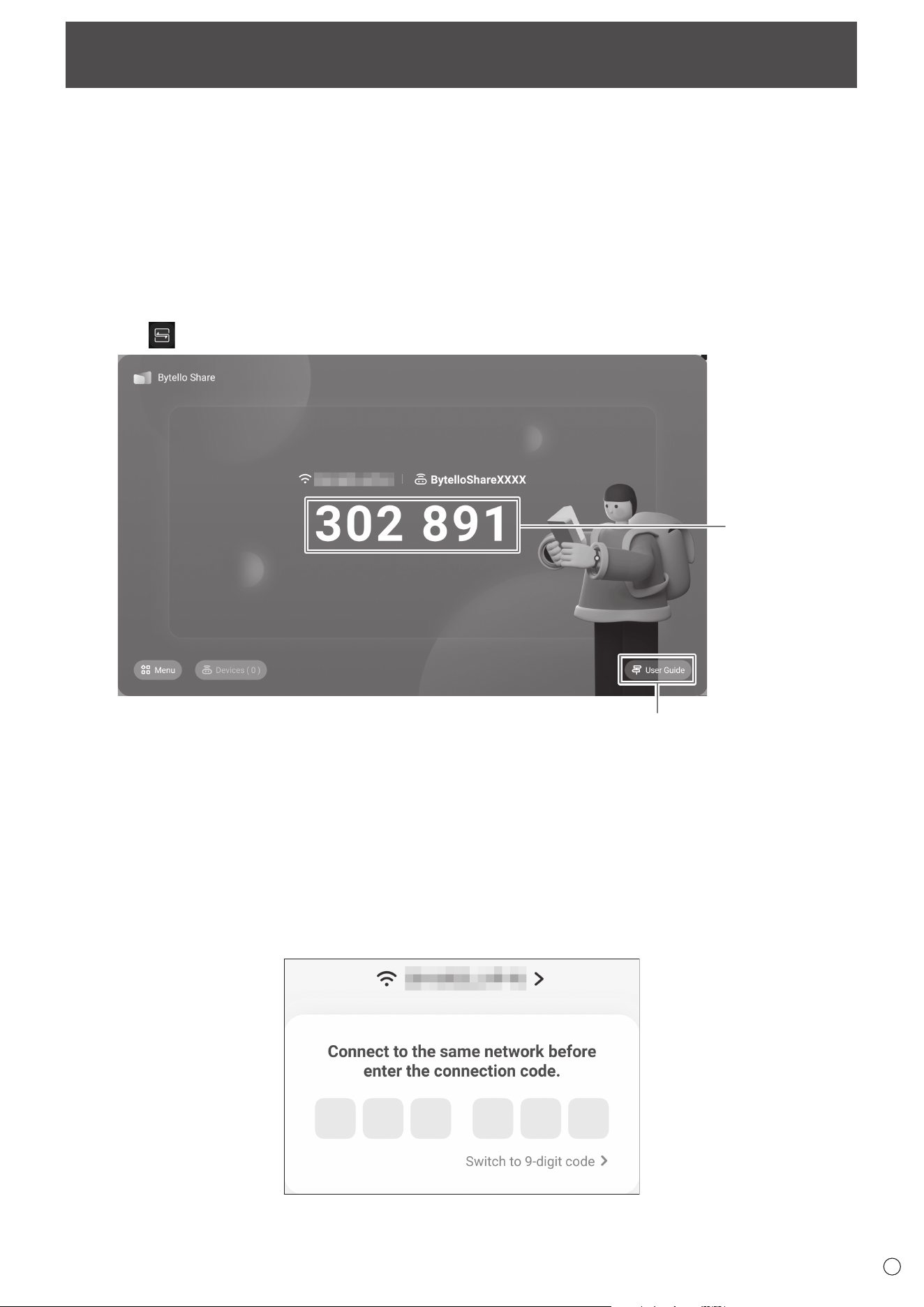
Startup
When the application is first started, it is necessary to connect to the Internet for the authentication of the application.
1. On the home screen of APPLICATION mode, touch “Bytello Share”.
Or, touch
on the toolbar.
Connection code
Display the user guide.
n
Preparing the device
• You must connect to the Internet.
• Access the URL specified in “User Guide”, and the download and install the application.
You can also access by scanning the QR code.
n
Operating the device
• The screen is simply an example. It varies depending on the version of the device (OS) and application.
1. Connect to the same network as this monitor, and start the application.
(This monitor does not support 9-digit codes.)

36
E
Bytello Share
2. Enter the connection code displayed on this monitor.
This monitor and the device are connected.
• Screen Share ..........................................................Displays the device screen.
• Media ...................................................................... Displays or plays back the videos and music saved in the device.
• Photo ......................................................................Displays the photos and images saved in the device.
• Document ...............................................................Displays the document files saved in the device.
• Camera ...................................................................Shares the camera images on the device.
• Remote ................................................................... Operates this monitor from the device.
• Desktop Sync .........................................................Displays this monitor screen on the device.
* The tasks that can be performed vary depending on the version of the terminal (OS) and application.
n
MAKING THE SETTINGS
1. Touch “Menu” and “Settings”.
Allow this device to be discovered
Sets whether the device allows the search and connection of this monitor.
Permissions Mode
Sets whether or not to confirm on this monitor when the device transmits a screen.
Support Chromecast device
Support iOS device
Support Miracast device*
Turn ON to use.
Device Name
Changes the name of this monitor displayed on the device that transmits or receives images.
Start automatically on boot
Sets whether or not to automatically start “Bytello Share” when this monitor is turned ON.
Code refresh rate
Sets the interval to update the connection code.
Floating window size
Sets whether or not to display the connection code on a screen other than “Bytello Share”.
Normal size............................ Display the connection code.
Mini size................................. Display
.
If you touch
, the connection code is displayed.
Close ..................................... Not displayed.
* Supported only by wireless LAN connection.
37
E
PDF Viewer
Starts when a PDF file is opened on an application such as “File Explorer”, etc.
(1)
(3)
(2)
(1) Displays the PDF.
Zoom-in or zoom-out the display by pinching.
Magnify the display by double-tap.
: Displays the current page / total number of pages.
: Performs printing.
(2) Close / display the bookmark.
(3) Exit the application.

38
E
File Explorer
Manages the files and folders in the internal storage and the USB flash drive connected to the monitor.
You can also display or play back the files.
1. On the home screen of APPLICATION mode, touch “File Explorer”.
Select the device
to display.
n
Creating a new folder
1. Touch “Create”.
A dialog box for the input of the folder name appears.
2. Input the folder name.
• Up to a maximum of 255 alphanumeric characters.
3. Once input is complete, touch “OK”.
n
Copying/Moving
1. Display the file/folder to be copied/moved.
2. Touch “Select” to select the file/folder to be copied/moved.
• You can even select multiple files/folders.
You can select all files/folders with “SelectAll”.
3. Touch “Copy”or “Cut”.
4. Display the file list of the copy/move destination.
5. Touch “Paste”.
The file/folder is copied/moved.
n
Deleting
1. Display the file/folder to be deleted.
2. Touch “Select” to select the file/folder to be deleted.
• You can even select multiple files/folders.
You can select all files/folders with “SelectAll”.
3. Touch “Delete”.
A confirmation screen appears.
4. Touch “OK”.
n
Renaming
1. Display the file/folder to be renamed.
2. Touch “Select” to select the file/folder to be renamed.
3. Touch “Rename”.
4. Enter the new name, and then touch “OK”.
■Exiting
1. Touch “Exit”.
39
E
File Explorer
n
Supported formats
You can play image, music, and video files.
The types of files that can be played are as follows.
Image files
Extension Max. resolution
*.bmp
3840x2160*.jpg (*.jpeg)
*.png
• Progressive JPEG files are not supported.
Music files
Extension Audio coding Sample rate Bit rate
*.mp3 MPEG1/2 layer3 8kHz - 48kHz 8kbps - 320kbps
Video files
Extension Video coding Audio coding Max. resolution Maximum bit rate
*.mkv
vp9
(Profile 0 (420 8bit),
Profile 2 (420, 10bit))
Mpeg1/2 Layer1/2/3,
AAC-LC,
LPCM,
opus
4096x2160@60fps 60Mbps
VP8 1920x1080@60fps 60Mbps
H.265
(Main/Main10 Profile,
High Tier @Level 6.1)
4096x2160@60fps 200Mbps
H.264
(BP, MP, HP @
level5.1)
3840x2160@30fps 160Mbps
Mpeg-4
( Simple Profile,
Advanced Simple,
Profile@Level 5)
1920x1080@60fps 80Mbps
mpeg1/2 (MP @HL) 1920x1080@60fps 80Mbps
*.mp4
H.265
(Main/Main10 Profile,
High Tier @Level 6.1)
Mpeg1/2 Layer1/2/3,
AAC-LC,
vorbis,
LPCM,
AMR-NB
4096x2160@60fps 200Mbps
H.264
(BP, MP, HP @
level5.1)
4096x2160@60fps 200Mbps
Mpeg-4
( Simple Profile,
Advanced Simple,
Profile@Level 5)
1920x1080@60fps 80Mbps
mpeg1/2 (MP @HL) 1920x1080@60fps 80Mbps
In some cases it may not be possible to play the above files.

40
E
Web Browser
Browses the home page.
1. On the home screen of APPLICATION mode, touch “Web Browser”.
Exiting
Close the Web Browser from the recent app bar.
TIPS
• If a large-sized website is displayed, the Web Browser may close.
Caution
• Take proper care when browsing websites.
In a malicious website, the input contents may be stolen and fraudulent applications may be downloaded.
If a fraudulent application is installed, it may result in a virus infection or stealing of communication details.
• Be sure to log out from a website that you have used by logging in.
If you remain logged in, your personal information such as the ID may be known by a third person.
41
E
Updating the Software (Update)
Update applications that are factory-installed in APPLICATION mode. (A network environment that allows access to the internet
is required.)
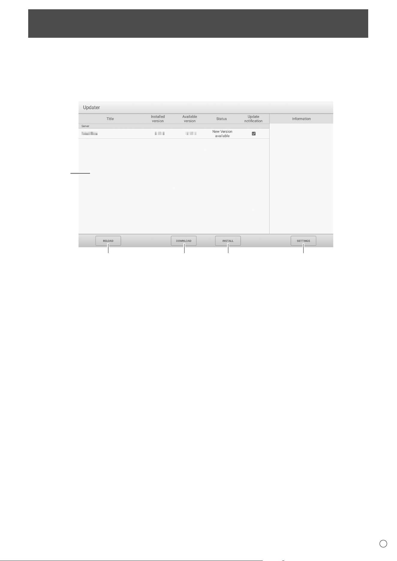
On the home screen of APPLICATION mode, touch “All Apps”, and then touch “Updater”.
When you use Updater, a password is required. (Factory setting) (See page 45.)
The “Export Law Assurances” appears. Select “OK”.
To use the software distributed by the Updater, you must agree to the “Export Law Assurances”.
1
2 3 4 5
1. Information area
Shows information on already downloaded software and software that can be downloaded.
Update notification: Displayed when “Notify new versions” is set to on. Update of software that unchecked will not be
notified.
2. RELOAD
Refresh the information in the information area.
3. DOWNLOAD
Download the selected software.
4. INSTALL
Install the selected software.
5. SETTINGS
Configure settings for Update.
• Hide updated items ....................................... Set whether or not to hide updated softwares in the information area.
• Notify new versions ....................................... Set whether or not to display a message if updated software exists.
• Scheduled installation ................................... Set whether or not to update the software automatically.
• Scheduled installation day ............................ When “Scheduled installation” is set to on, set the day of week to update
the software automatically.
• Scheduled installation time ........................... When “Scheduled installation” is set to on, set the time to update the
software automatically.
• Proxy ............................................................. Set whether or not to use this monitor in a proxy environment.
• Proxy settings ............................................... When “Proxy” is set to on, set the host name, port, username, and
password of the proxy.
• About Updater. ..............................................Display the information of this application.
• Reset ............................................................Initialize the “SETTINGS”.
42
E
Common Settings Menu
Displaying the menu screen
Adjusts the images and sound.
Caution
• Do not turn the main power switch off while the menu items are being displayed. Doing so may initialize the settings.
n
Example of operation
1. On the home screen of APPLICATION mode, select “Common Settings”.
Or, press the MENU button on the remote control unit.
The Common Settings menu appears.
2. Select the tab and adjust each item. (See below.)
Select
to display the Input menu.
3. Once the settings are complete, touch other than the Common Settings menu.
Or, press the RETURN buttton on the remote control unit.
TIPS
• When press the MENU button on the remote control unit, the Common Settings menu may appear above the application’s
menu. Close the Common Settings menu to operate the application’s menu.
Menu item details
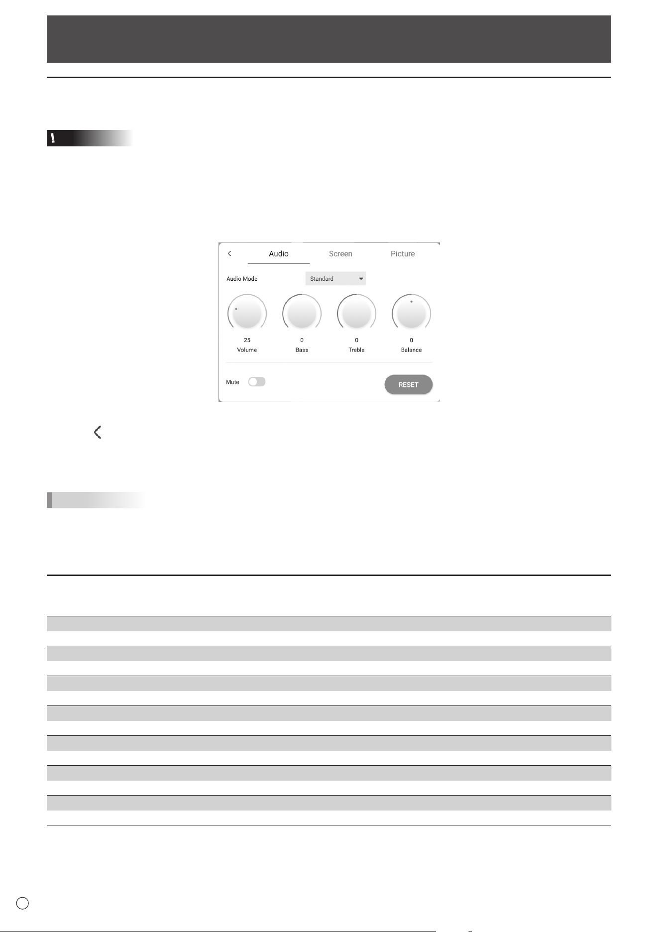
n
Audio
Sound Mode
Selects the sound mode.
Volume
Adjusts the volume.
Bass
Adjusts the volume of bass-level sound. You can set this when the “Sound Mode” is set to “Custom”.
Treble
Adjusts the volume of treble-level sound. You can set this when the “Sound Mode” is set to “Custom”.
Balance
Adjusts the balance of the audio sound between right and left.
Mute
Sets whether or not to mute the audio.
RESET
Resets the values of the Audio menu items to the factory default settings.
43
E
n
Screen
H Position (D-SUB)
Adjust the horizontal position of the image.
V Position (D-SUB)
Adjust the vertical position of the image.
Clock (D-SUB)
Adjusts frequency for sampling clock for applicable video. Adjust when there is flickering in the form of vertical stripes.
When using the adjustment pattern (see page 44), make adjustments so that no vertical stripe noise appears in it.
Phase (D-SUB)
Adjusts sampling clock phase for applicable video. Useful when small characters appear with low contrast and/or there are
flickers at corners. When using the adjustment pattern (see page 44), make adjustments so that no horizontal stripe noise
appears in it.
* Adjustments to “Phase” should be made only after “Clock” has been correctly set.
AUTO (D-SUB)
The “Clock”, “Phase”, “H Position”, and “V Position” are automatically adjusted.
Executed when “AUTO” is selected. Use this automatic adjustment when you use the D-SUB to display a computer screen for
the first time or when you change the setting of the computer. (See page 44.)
Size (HDMI/D-SUB/USB-C/OPS)
Changes the screen size. (See page 26.)
RESET
Resets the values of the Screen menu items to the factory default settings.
n
Picture
Color Mode (HDMI/D-SUB/USB-C/OPS)
Selects color mode for the screen.
Black Level (HDMI/D-SUB/USB-C/OPS)
Adjusts the entire brightness of the video signals. You can set this when the “Color Mode” is set to “Custom”.
Contrast (HDMI/D-SUB/USB-C/OPS)
Adjusts the difference between the bright and dark portions of the image. You can set this when the “Color Mode” is set to
“Custom”.
White Balance
Selects the white balance.
RESET
Resets the values of the Picture menu items to the factory default settings.
Common Settings Menu
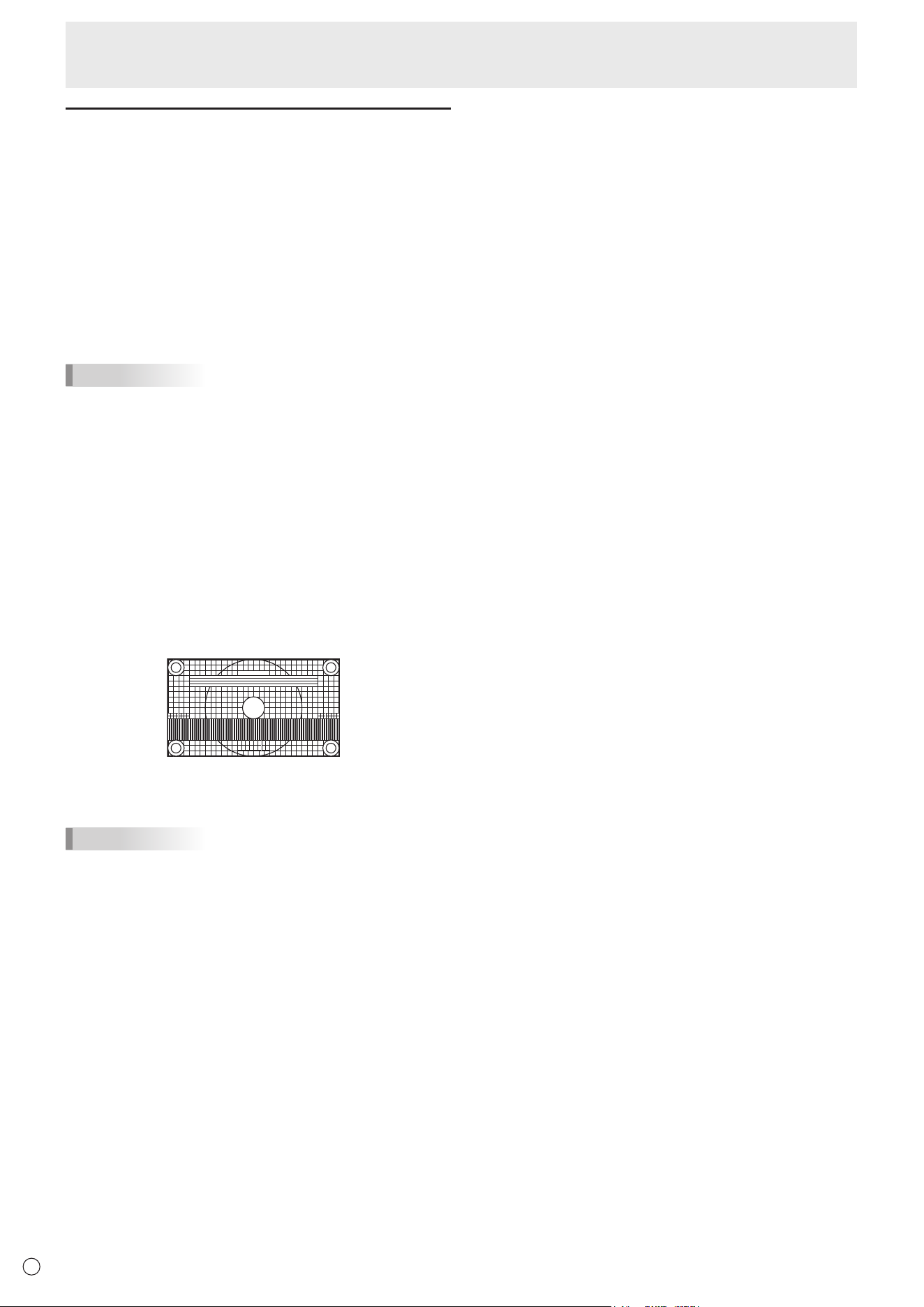
44
E
Adjustments for computer screen display
n
Automatic adjustment
When you use the “D-SUB” to display a computer screen for
the first time, or when you change the setting of the computer,
use the automatic screen adjustment.
1. Switch the input to “D-SUB” and display the
adjustment pattern. (See the description below.)
2. Display the Screen menu on “Common Settings”.
3. Select “AUTO”.
The automatic adjustment is complete in several seconds.
4. Press the MENU button to close the menu screen.
TIPS
• If the screen cannot be adjusted properly with one
automatic adjustment, repeat the automatic adjustment two
or three times. Try manual adjustment if necessary.
n
Screen display for adjustment
Before making adjustments in the Screen menu or Picture
menu, display an image to brighten the entire screen. If you
are using a Windows computer, use the adjustment pattern.
Download the adjustment pattern by using Information Display
Downloader.
Opening the adjustment pattern
1. Double-click [Adj_uty.exe] downloaded.
The adjustment pattern will appear.
Adjust the screen automatically or manually.
2. When adjustment is finished, press the [Esc] on the
computer’s keyboard to quit the adjustment program.
TIPS
• If the display mode on the computer you are using is 65000
colors, the color levels in the color pattern may appear
differently or grayscale may appear to be colored. (This
is due to the specifications of the input signal and is not a
malfunction.)
Common Settings Menu
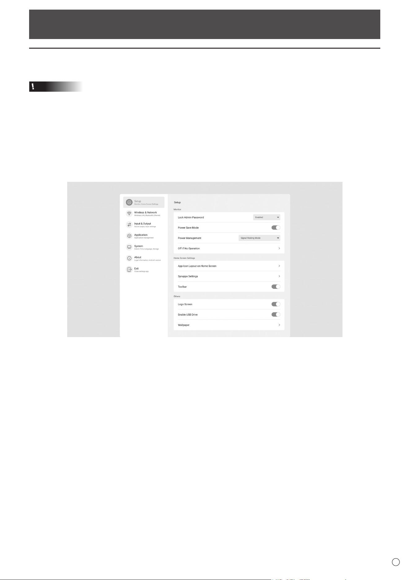
45
E
Administrator Settings Menu
Displaying the menu screen
Makes settings for this monitor.
Caution
• Do not turn the main power switch off while the menu items are being displayed. Doing so may initialize the settings.
Touch to operate.
1. On the home screen of APPLICATION mode, touch “Administrator Settings”.
• When you use Administrator Settings, a password is required. (Factory setting)
A screen for the input of the password appears.
• When you use Administrator Settings for the first time, a Set Password screen appears. Set a password.
2. Enter the password, and then touch “OK”.
To change the password, touch “Change the admin password”.
The Administrator Settings menu appears.
3. Set each item. (See page 46.)
4. Once the settings are complete, touch “Exit”.
46
E
Administrator Settings Menu
Menu item details
n
Setup
Monitor
Lock Admin Password
Sets whether or not a password is necessary when using “Administrator Settings”, “FUNCTION”, and “Updater”.
Power Save Mode
When set to off, startup time from standby state is reduced. Note, however, that more power will be consumed in standby
state. Android continues to run in standby state.
When set to on, standby state is standby mode. Current consumption is reduced while the monitor is in standby state.
Android is also shut down. Note, however, that the startup time from standby state becomes longer.
If set to on, certain RS-232C commands cannot be used in standby mode. (See pages 51.)
Power Management
Sets whether or not to move to input signal waiting state or standby state in the nosignal state.
Disabled .............................................. Do not move.
Signal Waiting Mode ........................... Move to input signal waiting state.
Power Standby ....................................
If the nosignal state continues for approximately 5 minutes, the monitor moves to the standby state.
The application data that is not saved is lost.
Off if No Operation
Determines whether or not to set the monitor to go into standby state when there is no operation by the remote control unit,
touch or RS-232C control.
Home Screen Settings
App Icon Layout on Home Screen
Sets the icons of the applications to be arranged on the home screen of APPLICATION mode.
Synappx Settings
Synappx Setting .................................. Sets whether or not to display the “Synappx” icon on the home screen of
APPLICATION mode.
Input for Synappx ................................ When “Synappx Setting” is set to on, sets the input terminal to which the computer on
which Synappx is installed is connected.
Toolbar
Sets whether or not to display the toolbar.
Others
Logo Screen
Sets whether or not to display the logo screen when turning the power on.
Enable USB Drive
Sets whether or not to allow the use of a USB flash drive.
Wallpaper
Sets the background of the home screen of APPLICATION mode.
■Wireless&Network
Wireless&Network
Wireless LAN
Sets whether or not to use a wireless LAN when installing a wireless adapter. To use a wireless LAN, set the access points.
You cannot use the “Ethernet” when using a “Wireless LAN”.
Ethernet
Sets whether or not to use a LAN terminal.
To use a LAN terminal, set the IP address, etc. You cannot use a “Wireless LAN” when using the “Ethernet”.
Bluetooth
Set whether or not to use a commercially available Bluetooth device.
Configure settings for Bluetooth.
47
E
Administrator Settings Menu
n
Input&Output
Sound
Audio Output
Sets the volume of sound output from the audio output terminal.
Variable1 ..................... You can adjust the volume from the speakers of this monitor and the audio output terminal
simultaneously by using “Volume”.
Variable2 ..................... You can adjust the volume from the audio output terminal by using “Volume”.
Sound will not be output from the speakers of this monitor.
Fixed ........................... Fixes the volume from the audio output terminal. Adjust the volume by using an external device.
Mute with Freeze
Set whether or not audio turns off during freeze.
Input Settings
Auto Input Change
Sets whether the input into the input terminal automatically changes when a video signal is input into that terminal. The input
via the expansion slot is ignored. (With some input signals, the input may not change.)
Input Mode Name
For each terminal, you can change the input mode name that is displayed during input mode selection or display.
External Source Display Settings
CEC Settings
Makes settings for linkage with devices connected to HDMI1 input terminal through HDMI CEC.
HDMI CEC Link
When this setting is set to on, the link will be used.
When this setting is set to off, the link will not be used.
Auto Power On ............ When “HDMI CEC Link” is set to on, sets whether or not to turn this monitor ON by linking to the
operation of the devices.
HDMI Modes
“HDMI Modes” settings change how the content displayed is processed and decoded using the HDMI input terminal.
Mode1 ......................... Normally used.
This will support most common color spaces and other encoding signals.
Mode2 ......................... Used when proper display cannot be performed in “Mode1”, such as when a device that is not
compatible with 4K is connected.
n
Application
Manages the installed applications.
n
System
Date&Time
Use 24-Hour Format
Sets whether or not to display the time in the 24-hour format.
AutomaticDate&Time
Sets whether or not to set the data & time automatically via network.
Set Date
Sets the date. Displayed when “Automatic Date & Time” is set to off.
Set Time
Sets the time. Displayed when “Automatic Date & Time” is set to off.
Date format
Sets the display format for the date.
Time Zone
Sets the time zone.
48
E
Administrator Settings Menu
Language&Keyboard
Language
Sets the display language for the screen.
Virtual Keyboard
Selects the keyboard to display on the screen.
Physical Keyboard
Displays information about the physical keyboard used.
Current Keyboard
Sets the language for the physical keyboard being used.
Show Virtual Keyboard ........................ Sets whether or not to display a keyboard on the screen when a physical keyboard is
connected.
Startup&Shutdown
Start Input Mode
You can set the input mode that will be in effect when the power is turned on.
When this is set to “Last Input Mode”, the input mode when the power was last turned off will appear.
* When “Auto Input Change” is set to on and there is no input signal in the set input mode, the input mode changes to
APPLICATION mode.
Startup App
When “Start Input Mode” is set to “APPLICATION”, sets the applications to be started automatically.
Sleep After Startup
Sets whether or not to move to sleep state (backlight off) after startup.
Power Off Reminder
Sets whether or not to display a confirmation message when the power off schedule is executed.
Add Power On Schedule
Power can be turned ON at the specified time.
Add Power Off Schedule
Power can be turned OFF at the specified time.
Storage
Displays the capacity of the internal storage of this monitor and the external storage connected to this monitor.
System Update
Confirms the firmware version and updates the firmware.
Current Version
Displays the current firmware version.
Update
If you connect the USB flash drive containing the firmware to this monitor and then touch “Check”, the firmware will be
updated.
Security
Trusted Credentials
Displays the trusted credentials.
User Credentials
Displays the user credentials.
Install From Storage
Installs a file from the connected storage.
Clear credentials
Deletes all credentials.
n
About
Displays the information of the monitor.

49
E
Administrator Settings Menu
n
Schedule
You can set the time to switch the monitor on and off.
Set this function with “Startup & Shutdown” in the System
menu. (See page 48.)
1. To turn the power ON at the specified time, touch “Add
Power On Schedule”.
To turn the power OFF at the specified time, touch “Add
Power Off Schedule”.
2. Set the time and day of implementation.
3. Touch “Save”.
The schedule is displayed as a list.
4. Turn on the schedule.
You can also turn off the schedule.
Caution
• Do not switch off the main power after setting the schedule.
• Specify the correct date and time. (See page 47.)
Schedule does not function unless the date and time are
specified.
• Check regularly that the set date and time are correct.
• In the power off schedule, a message is displayed on the
screen approx. 1 minute before the power turns off. If you
select “Cancel”, you can stop the power from turning off.
(When “Power Off Reminder” is set to on.)
• The power on schedule and power off schedule must be
set at an interval of 5 minutes or more.
TIPS
• Up to 14 “Schedule” items can be registered.
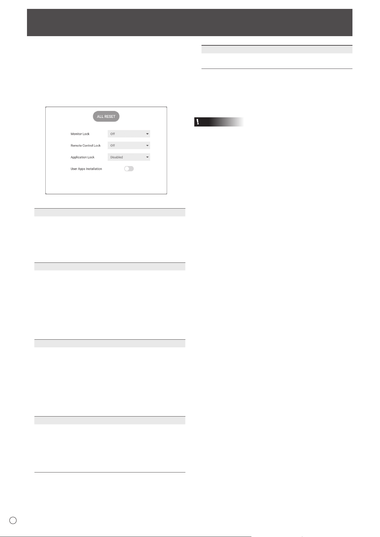
50
E
Reset/Functional Restriction Setting (FUNCTION Menu)
You can reset the settings to the factory default settings
or restrict operations. When you use FUNCTION menu, a
password is required. (Factory setting) (See page 45.)
Perform the operation from the remote control unit.
1. Press the FUNCTION button, and then press the MENU
button within 10 seconds.
The FUNCTION menu appears.
2. Select and set the items.
ALL RESET
Resets the settings to the factory default settings.
In “APPLICATION” mode, only the settings of the factory-
installed applications are initialized.
If you select “ALL RESET”, a confirmation message is
displayed. Select “All Reset”.
This monitor restarts when initialization ends.
Monitor Lock
You can disable operations on the monitor that use buttons.
Off:
Enables operation.
Power Button:
Locks Power Button operation.
Touch:
Locks touch operation.
Power Button & Touch:
Locks Power button and touch operation.
Remote Control Lock
You can disable operations on the remote control unit that
use buttons.
Off:
Enables operation.
All:
Locks all button operations.
Except Power & Volume:
Locks operations other than power operation and
VOLUME +/-.
Application Lock
Sets whether or not to lock the use of the following
application.
• Updater
• Synappx
• Bytello Share
• Web Browser
User Apps Installation
Sets whether or not to allows the installation of
applications by the apk file.
Closing the FUNCTION menu
• Press the MENU button or RETURN button on the remote
control unit.
• Touch other than the FUNCTION menu.
Caution
• Applications installed by customers are out of scope of
guarantee.
• Check the safety of applications.
Some applications may affect the operation of other
applications and this monitor.
Also, there is a possibility of a virus infection, data
corruption, falsification, or leakage.
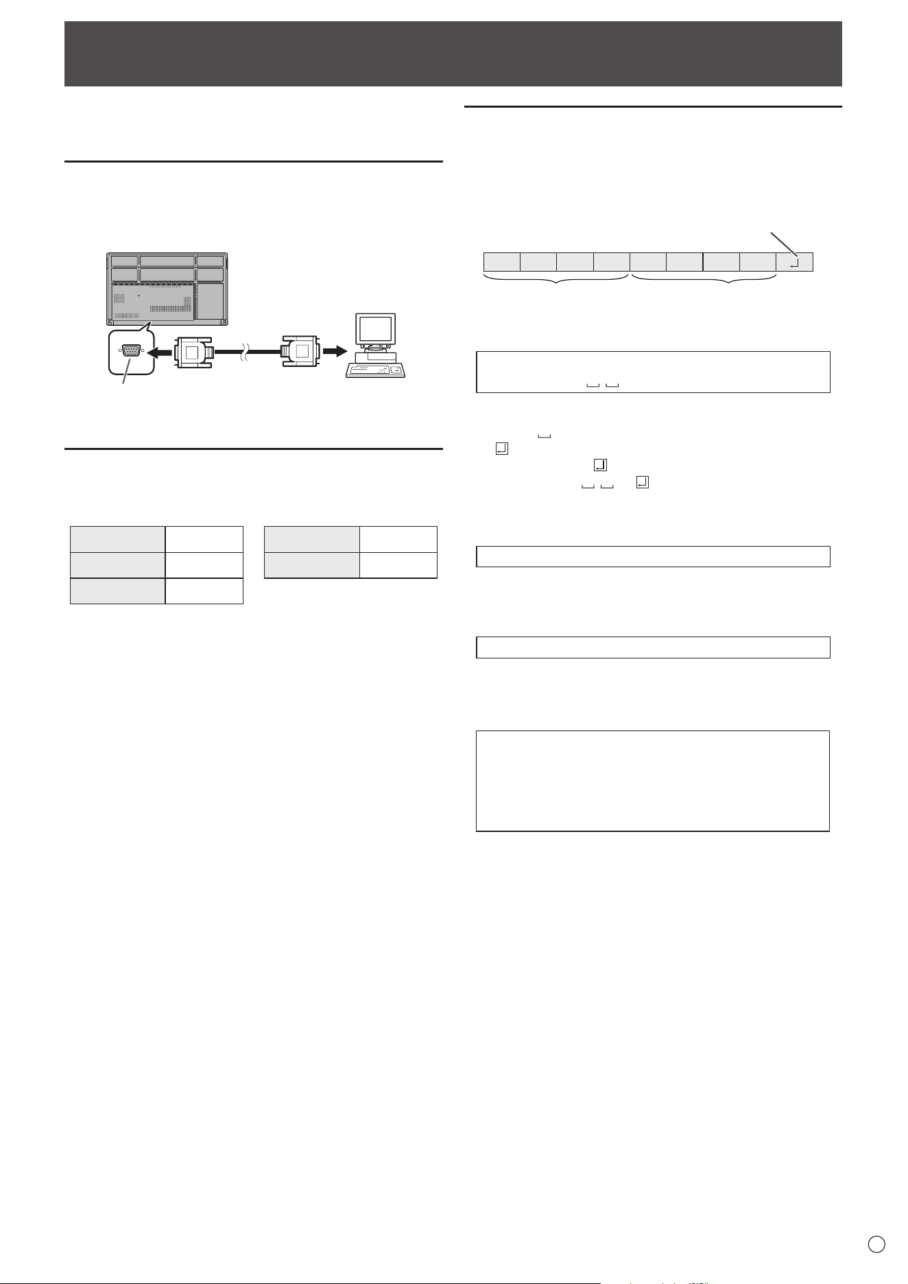
51
E
Controlling the Monitor with a computer (RS-232C)
You can control this monitor from a computer via RS-232C
(COM port) on the computer.
Computer connection
Connect with RS-232 straight cable between the computer’s
COM port (RS-232C connector) and the RS-232C input
terminal on the monitor.
RS-232C
input terminal
RS-232 straight cable
(commercially available)
To COM port
Computer
Communication conditions
Set the RS-232C communication settings on the computer to
match the monitor’s communication settings as follows:
Baud rate 9600 bps
Stop bit
1 bit
Data length 8 bits Flow control None
Parity bit None
Communication procedure
n
Command format
When a command is sent from the computer to the monitor,
the monitor operates according to the received command and
sends a response message to the computer.
C1 C2 C3 C4 P1 P2 P3 P4
Return code
Command field
(4 prescribed
alphanumerical characters
)
Parameter field
(4 character string comprised of:
0-9, +, -, space, ?)
Example: VOLM0030
VOLM
30
* Be sure to input 4 characters for the parameter. Pad with
spaces (“
”) if necessary.
(“
” is a return code (0D
H
, 0A
H
or 0D
H
))
Wrong : VOLM30
Right : VOLM 30
When inputting a negative value, specify a numerical value in
three digits.
Example: OFSR-127
When the parameter part is 5 or more characters, specify
parameters using a specified number of characters without
using spaces.
Example: MPOS010097
If a command has “R” listed for “Direction” in the
“RS-232C command table” on page 53, the current value can
be returned by using “?” as the parameter.
Example:
VOLM ? ? ? ? ←
From computer to monitor (How
much is current volume setting?).
30 ←
From monitor to computer
(Current volume setting: 30).
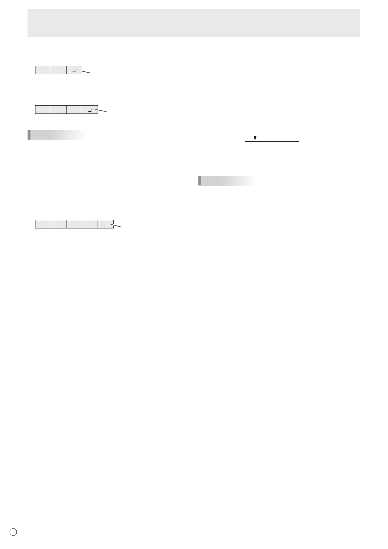
52
E
Controlling the Monitor with a computer (RS-232C)
n
Response code format
When a command has been executed correctly
O K
Return code
(0DH, 0AH)
A response is returned after a command is executed.
When a command has not been executed
R R E
Return code
(0DH, 0AH)
TIPS
• “ERR” is returned when there is no relevant command or
when the command cannot be used in the current state of
the monitor.
• If communication has not been established for reasons
such as a bad connection between the computer and
monitor, nothing is returned (not even ERR).
•
“ERR” may be returned when a command cannot be received
correctly due to interference from the surrounding environment.
Please ensure that the system or software resends the
command if this occurs.
If execution of the command is taking some time
I W T A
Return code
(0DH, 0AH)
When the following commands are used, “WAIT” is returned.
In this case, a value will be returned if you wait a while. Do not
send any command during this period.
• Commands which return “WAIT”:
RSET, POWR, INPS, ASNC, BOMD, WIDE
n
Communication interval
• After “OK” or “ERR” is returned, you must send the
following commands.
To set a timeout for the command response, specify 10
seconds or longer.
• Provide an interval of 100 ms or more between the
command response and the transmission of the next
command.
VOLM0020
OK
INPS0001
WAIT
OK
Interval of 100 ms or more
TIPS
• When “ALL RESET” is executed, this monitor will restart.
Wait at least 1 minute before sending the next command.
• Before sending a power “On” or “Off” command, it is
recommended that you perform buffer clear at the sending
application side.
• After executing a power “On” or “Off” command, wait at
least 1 minute before sending the next command.
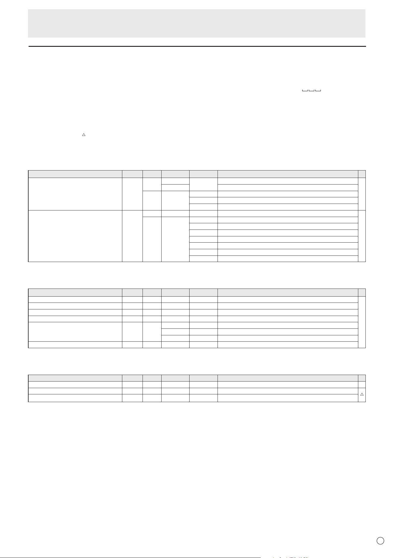
53
E
RS-232C command table
How to read the command table
Command: Command field (See page 51.)
Direction: W When the “Parameter” is set in the parameter field (see page 51), the command functions as described
under “Control/Response Contents”.
R The returned value indicated under “Reply” can be obtained by setting “????” or “
?” in the
parameter field. (See page 51.)
Parameter: Parameter field (See page 51.)
Reply: Response (Returned value)
*: “●”: Indicatesacommandwhichcanbeusedinstandbystate,inputsignalwaitingstateorwhenthe
power is on.
“○”: Indicatesacommandwhichcanbeusedininputsignalwaitingstateorwhenthepowerison.
“ ” : Indicates a command which can be used in standby state or when power is on.
“–” : Indicates a command which can be used when the power is on.
Power control/Input mode selection
Function
Command Direction
Parameter Reply Control/Response contents *
Power control POWR W 0
Switches to standby state.
●
1 Returns from standby state.
R 0 Standby state
1 Normal mode
2 Input signal waiting state
Input mode selection INPS W 0 Toggle change for input mode.
○
WR 2 D-SUB
10 HDMI1
13 HDMI2
18 HDMI3
21 OPTION
24 APPLICATION
27 USB-C
Common Settings menu
Function
Command Direction
Parameter Reply Control/Response contents *
Volume VOLM WR 0-100 0-100
-
Mute MUTE WR 0-1 0-1 0: Off, 1: On
Size (Screen size selection) WIDE WR 1-3 1-3 1: Wide, 2: Normal, 3: Dot by Dot
Auto ASNC W 1 When the input mode is D-SUB.
Color Mode BMOD WR 0 0 Standard
4 4 High Illuminance
8 8 Custom
White balance WHBL WR 0-3 0-3 0:Thru, 1:Standard, 2:Warm, 3:Lamp
Administrator Settings menu
Function
Command Direction
Parameter Reply Control/Response contents *
Date & Time Settings DATE WR
AABBCCDDEE AABBCCDDEE
AA: Year, BB: Month, CC: Day, DD: Hour, EE: Minute -
Model INF1 R Value
Serial no. SRNO R Value
Controlling the Monitor with a computer (RS-232C)
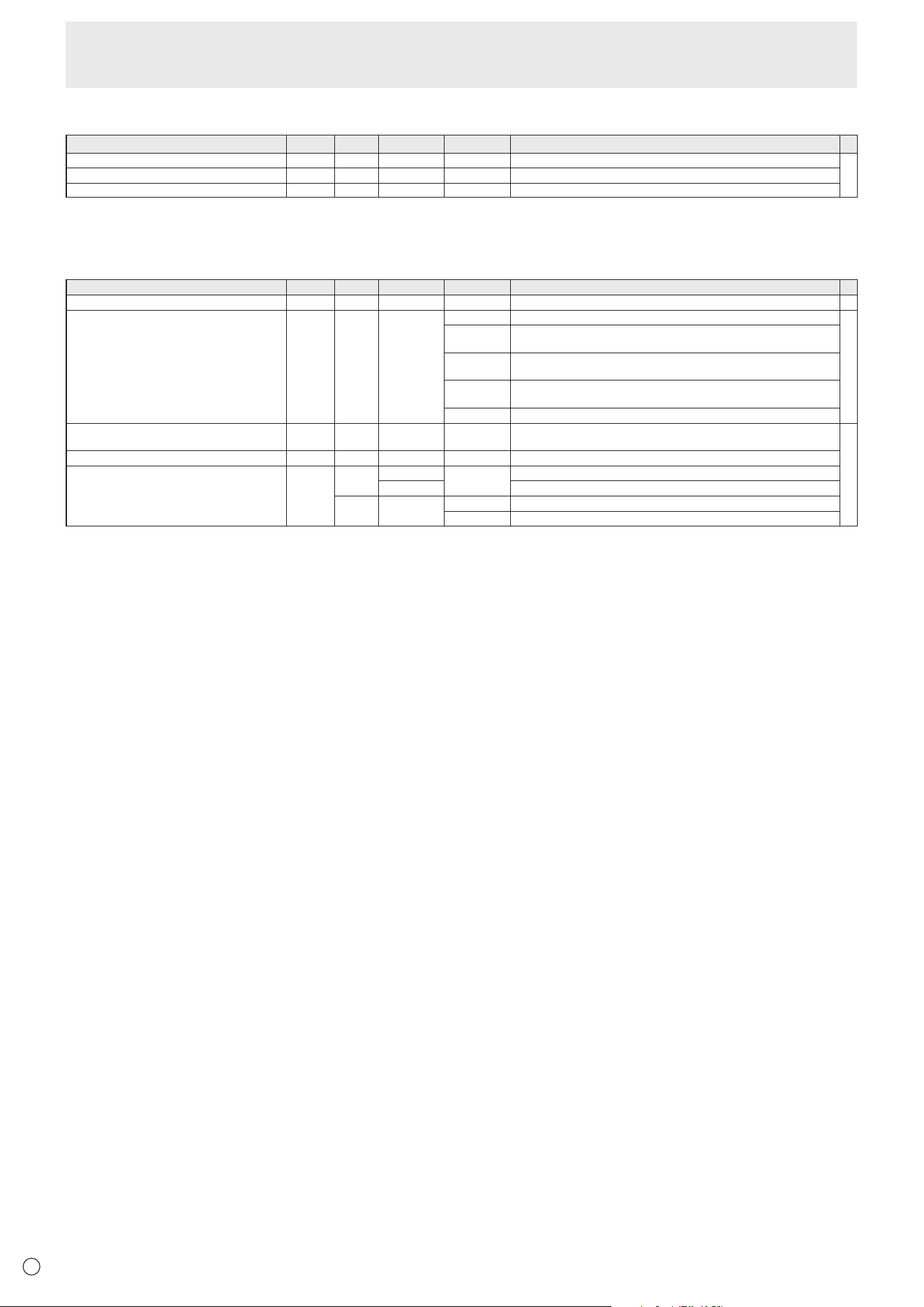
54
E
Function menu
Function
Command Direction
Parameter Reply Control/Response contents *
Monitor Lock ALCM WR 0-3 0-3 0: Off, 1: Power Button & Touch, 2: Power Button, 3: Touch
-
Remote Control Lock ALCR WR 0-2 0-2 0: Off, 1: All, 2: Except Power & Volume
All Reset RSET W 0 0: All Reset
Others
Function
Command Direction
Parameter Reply Control/Response contents *
Bright VLMP WR 0-100 0-100 -
Temperature sensor DSTA R 0 Internal temperature normal
●
1 Internal temperature abnormal has occurred and the monitor is in standby
state
2 Internal temperature abnormal occurred (To delete the information of
temperature abnormal, turn off the main power.)
3 Internal temperature abnormal has occurred and backlight brightness is
dimmed
4 Temperature sensor abnormal
Temperature acquisition ERRT R Value Returns the temperature at the temperature sensors.
Indicates a temperature sensor abnormality when “126” is returned.
-
Check the resolution PXCK R - Returns current resolution in the form of hhh, vvv.
Sleep (Backlight off) BOMD W 0 Move to Sleep (Backlight off) state
1 Returns from Sleep (Backlight off) state
R 0 Sleep (Backlight off) state
1 Normal operation (Backlight on) state
Controlling the Monitor with a computer (RS-232C)

55
E
Troubleshooting
If you are experiencing any problem with your display, before
calling for service, please review the following troubleshooting
tips.
There is no picture or sound.
• The power LED is off.
- Is power supplied to this monitor?
- Is the power cord disconnected? (See page 14.)
- Is the main power switch off? (See page 18.)
• The power LED lights orange.
- This monitor is in standby state. Turn on the power. (See
page 18.)
• The power LED flashes blue.
- There is no input signal.
- Is an input mode selected that is appropriate for the input
terminal to which the cable is connected? (See page 25.)
- If any external equipment is connected, make sure the
equipment is operating (playing back).
Remote control does not work.
• Are the batteries inserted with polarity (+,-) aligned? (See
page 15.)
• Are the batteries exhausted?
• Point the remote control unit toward the monitor’s remote
control sensor. (See page 15.)
• Is operation disabled? (See page 50.)
The remote control unit’s buttons for operating the
HDMI-connected device do not work.
• Is the device connected to the HDMI1 input terminal?
HDMI2 input terminal and HDMI3 input terminal are not
supported.
• When the input mode is APPLICATION, these buttons
operate the application in APPLICATION mode.
• Is “HDMI CEC Link” set to on of “CEC Settings” on the “Input
& Output” menu?
• Switch to a different input mode, and then try switching the
input mode back to “HDMI1”.
Sound from left and right speakers is reversed.
Sound is heard from only one side.
• Are audio cables connected properly?
• Check the setting of “Balance” from the Audio menu. (See
page 42.)
There is a picture but no sound.
• Is the sound muted?
• Make sure the volume is not set to minimum.
• Are audio cables connected properly?
• Is the setting of “Audio Output” of “Sound” on the Input &
Output menu correct?
Unstable video.
• The signal may be incompatible.
•
Try the automatic screen adjustment when “D-SUB” is in use.
The video from the HDMI input terminal does not appear
properly.
• Does the HDMI cable support 4K, and is it HDMI standard
compliant? The monitor will not work with cables that are
not standard compliant.
• Is the input signal compatible with this monitor? (See pages
59 and 60.)
• If the connected device does not support 4K, set “HDMI
Modes” to “Mode2”.
The video from D-Sub input terminal does not appear
correctly.
• Is the input signal compatible with this monitor? (See page
59.)
The video from the USB Type-C does not appear properly.
• Is the input signal compatible with this monitor? (See page
59 and 60.)
Control buttons do not work.
There is no picture.
• Load noises from outside may be interfering with normal
operation. Turn off the main power and turn it on after
waiting at least 5 seconds, and then check the operation.
The input mode changes automatically.
• When “Auto Input Change” is on, the input mode
automatically changes to that terminal when a video signal
is input into the input terminal.
For this reason, the input mode may change when the
computer wakes up from system standby.
The touch panel does not respond.
• Is the USB cable connected properly?

56
E
Troubleshooting
The response of the touch panel is slow.
Some parts of the screen do not respond.
A different place is touched.
• Is the screen exposed to direct sunlight or other strong
light? The touch panel uses infrared rays and thus may not
operate correctly.
• Is there an obstacle between the infrared transmitter/
receiver and the touch pen or your finger? An obstacle will
prevent correct operation. If your fingers or a sleeve are too
close to the screen, correct operation will not be possible.
• Is the infrared transmitter/receiver dirty? Gently wipe off
any dirt with a soft cloth.
• If the touch panel is touched with a small tip less than about
1/16 inch (2 mm) x 1/16 inch (2 mm), the touch may not
be detected by infrared and correct operation will not take
place.
• Do not touch the touch panel when turning on the monitor.
If you touch the touch panel, this may be detected as an
element failure in the infrared transmitter/receiver and
incorrect operation will result.
• Set the screen size to “Wide”. (See page 26.)
When “AUTO DIMMING” is displayed.
• When the internal temperature of the monitor rises
excessively, the brightness of the backlight automatically
decreases in order to prevent a further temperature rise. If
you attempt to adjust the brightness while the monitor is in
this state, “AUTO DIMMING” is displayed and you cannot
change the brightness.
• Remove the cause of the excessive temperature rise.
The monitor makes a cracking sound.
• You may occasionally hear a cracking sound from the
monitor. This happens when the cabinet slightly expands
and contracts according to change in temperature. This
does not affect the monitor’s performance.
Power LED is flashing in orange and blue alternately.
When “TEMPERATURE” is displayed in the corner of the
screen.
• When the internal temperature of the monitor rises
excessively, the brightness of the backlight decreases
automatically in order to prevent high-temperature-
related problems. When this occurs, “TEMPERATURE” is
displayed on the screen and the Power LED flashes orange
and blue alternately.
• If the internal temperature rises further, the monitor
automatically enters standby state. (The Power LED
lighting orange.)
• Remove the cause of the excessive temperature rise.
- If the monitor enters standby state due to a rise in
temperature, to return to normal display, turn the
power switch off and then back on again. The monitor,
however, will enter standby state again if the cause of the
temperature rise is not eliminated.
- Check whether the monitor is placed at a location where
a quick rise in temperature is likely. Internal temperature
rises quickly if the vents on the monitor are blocked.
- Internal temperature rises quickly if dust accumulates
inside the monitor or around the vents. Remove dust if
possible. Ask SHARP dealer about removing internal dust.
No sound is heard from the speaker.
Mic cannot be used.
Web camera cannot be used.
• Check if another device is connected via the USB or
Bluetooth.
• If more than one equivalent devices are connected, they
will be used in the following order:
Bluetooth > USB > Internal (speaker only)
• Remove unnecessary devices.
• The mic of the Bluetooth headset cannot be used. This
monitor does not support HSP/HFP.
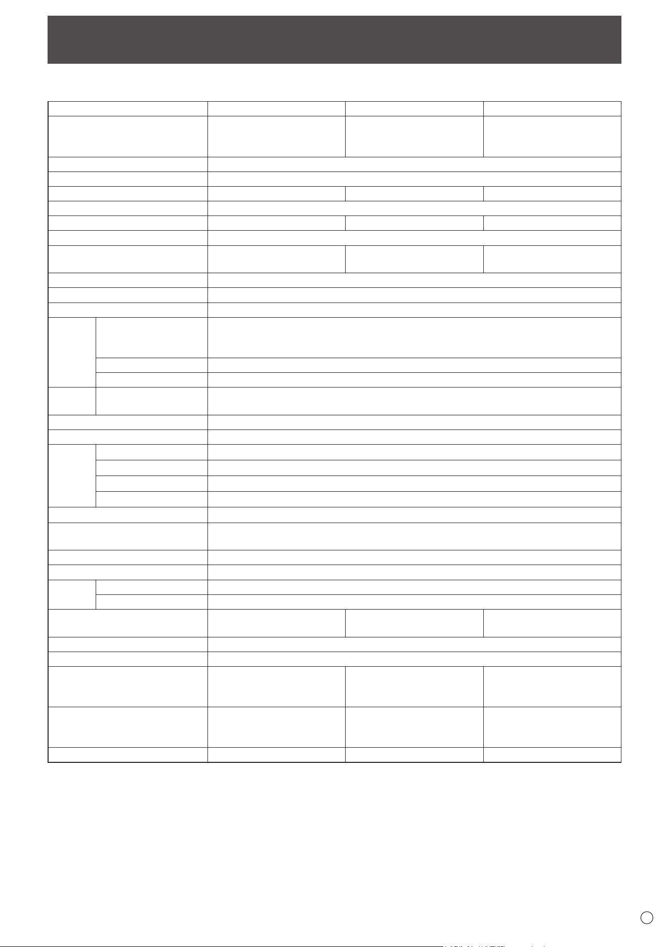
57
E
Specifications
n
Product Specifications
Model PN-L862B
PN-L752B
PN-L652B
LCD component
86" Class [85-9/16 inch
(217.4 cm) diagonal] TFT
LCD
75" Class [74-1/2 inch
(189.3 cm) diagonal] TFT
LCD
65" Class [64-1/2 inch
(163.9 cm) diagonal] TFT
LCD
Max. resolution (pixels)
3840 x 2160
Max. colors
Approx. 1.07 billion colors
Pixel pitch
0.4935 mm (H) × 0.4935 mm (V)
0.42975 mm (H) × 0.42975 mm (V)
0.372 mm (H) × 0.372 mm (V)
Brightness (typical) 400 cd/m
2
*
1
Contrast ratio (typical) 1200: 1 5000: 1 4000: 1
Viewing angle
178° right/left/up/down (contrast ratio ≥ 10)
Screen active area inch (mm)
74-5/8 (W) x 41-15/16 (H)
(1895.0 x 1066.0)
64-15/16 (W) x 36-9/16 (H)
(1650.2 x 928.3)
56-1/4 (W) x 31-5/8 (H)
(1428.5 x 803.5)
Computer input signal
Analog RGB (0.7 Vp-p) [75 Ω]
Sync signal
Horizontal/vertical separate (TTL: positive/negative)
Plug and play
VESA DDC2B
Input
terminals
Video Mini D-sub 15 pin, 3 rows x 1
HDMI x 3
USB Type-C x 1
Serial (RS-232C)
D-sub 9 pin x 1
Audio
3.5 mm mini stereo jack x 1
Output
terminals
Audio
3.5 mm mini stereo jack x 1
Digital audio output (optical) x 1
USB port USB 3.0 compliant x 4, USB 2.0 compliant x 1
LAN terminal 10 BASE-T/100 BASE-TX/1000 BASE-T
System OS Android 9.0
CPU Arm Cortex-A73 processor (Quad-Core)
Memory 4GB
Storage 32GB
Wireless LAN IEEE802.11ax/ac/n/a/g/b compliant
Bluetooth 5.0 compliant
Supported protocols: A2DP, AVRCP, GATT, HID
Expansion slot 20 V, 3.25 A (power supplied when expanding the functions with an optional part)
Speaker output 10 W + 10 W
Touch
Panel
Detection method Infrared blocking detection method
Computer connector USB (3.0 compliant) (Type B) x 2
Power requirement AC 100 - 240 V, 5.3 A,
50/60 Hz
AC 100 - 240 V
, 4.6 A,
50/60 Hz
AC 100 - 240 V, 3.7 A,
50/60 Hz
Operating temperature
*
2
*
3
41°F to 95°F (5°C to 35°C)
Operating humidity
*
3
20% to 80% (no condensation)
Power consumption
(input signal waiting state /
standby mode
*
4
/ off mode)
470W
(20W/0.5W/0.0W)
400W
(20W/0.5W/0.0W)
330W
(20W/0.5W/0.0W)
Dimensions inch (mm)
(excluding protrusions)
Approx. 77-1/16 (W) x 3-3/8
(D) x 45-5/8 (H) (1957 x 85.7
x 1159.5)
Approx. 67-5/16 (W) x 3-3/8
(D) x 40-1/8 (H) (1709.4 x
85.7x 1019.8)
Approx. 58-5/8 (W) x 3-3/8
(D) x 35-5/16 (H) (1488.4 x
85.5 x 896.6)
Weight lbs. (kg)
Approx. 137.8 (62.5) Approx. 109.1 (49.5) Approx. 80.5 (36.5)
*1 Brightness will depend on input mode and other picture settings. Brightness level will decrease over time. Due to the nature of the
equipment, it is not possible to precisely maintain a constant level of brightness. This is the brightness of the LCD panel, not the
brightness of the product.
*2 Temperature condition may change when using the monitor together with the optional equipments recommended by SHARP. In such
cases, please check the temperature condition specified by the optional equipments.
*3 In addition, check the requirements of the computer and other devices to be connected, and make sure that all requirements are satisfied.
*4 When no optional part is attached.
As a part of our policy of continuous improvement, SHARP reserves the right to make design and specification changes for product improvement
without prior notice. The performance specification figures indicated are nominal values of production units. There may be some deviations from
these values in individual units.
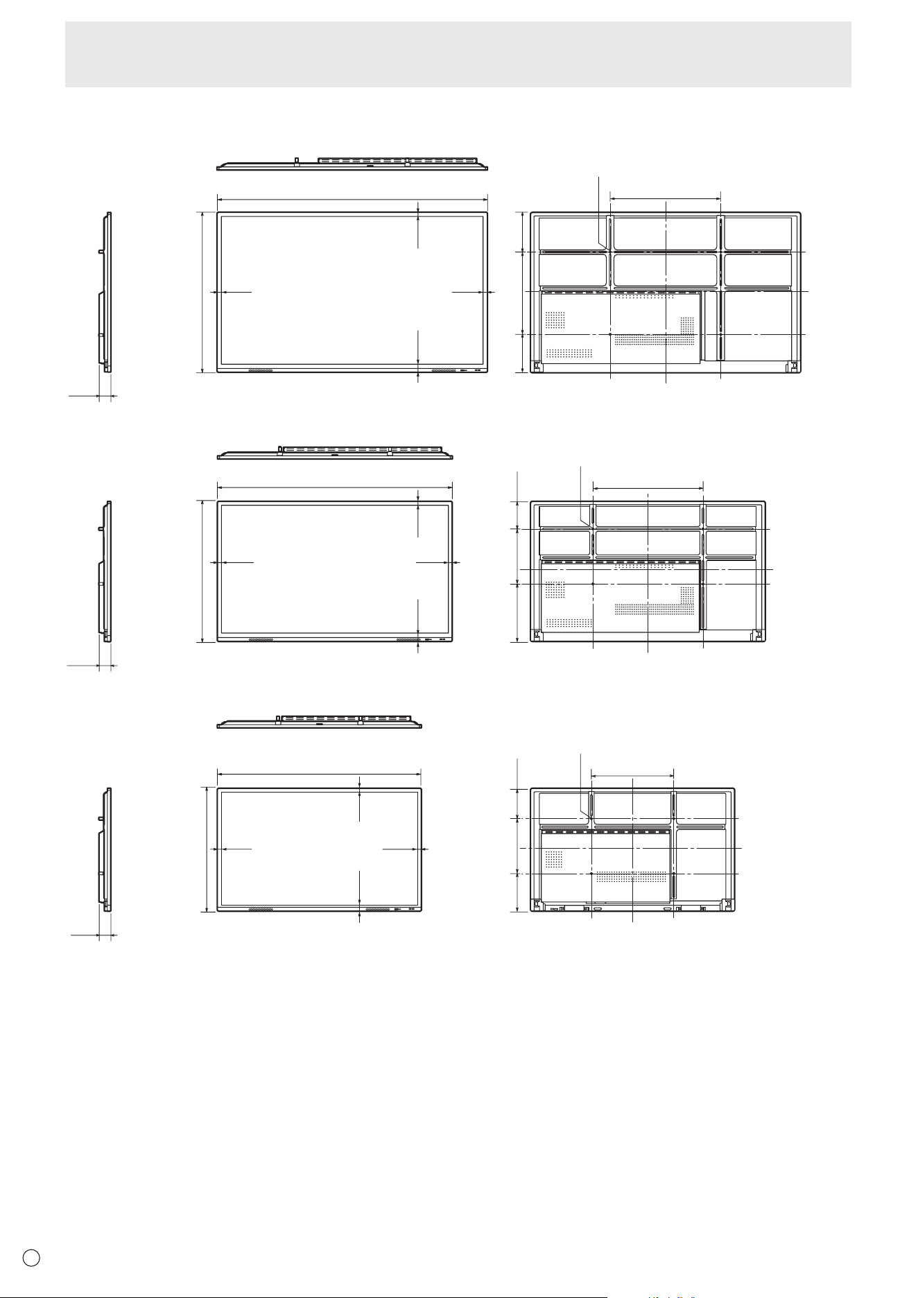
58
E
Specifications
n
Dimensional Drawings
Note that the values shown are approximate values.
45-5/8 [1159.5]
77-1/16 [1957]
1-11/16
[43.5]
9/16
[14.6]
Screw holes for mounting brackets
Unit: inch [mm]
[PN-L862B]
9/16
[14.6]
9/16
[14.6]
3-3/8
[85.7]
11-3/8
[288.8]
23-5/8
[600]
10-11/16
[270.8]
31-1/2 [800]
40-1/8 [1019.8]
67-5/16 [1709.4]
[PN-L752B]
1-11/16
[43.5]
9/16
[14.6]
9/16
[14.6]
9/16
[14.6]
3-3/8
[85.7]
7-7/8
[200.8]
15-3/4
[400]
16-1/2
[419]
31-1/2 [800]
Screw holes for mounting brackets
Unit: inch [mm]
35-5/16 [896.6]
58-5/8
[1488.4]
[PN-L652B]
1-11/16
[43.5]
9/16
[14.6]
9/16
[14.6]
9/16
[14.6]
8-3/4
[221.8]
15-3/4
[400]
10-13/16
[274.8]
23-5/8 [600]
3-3/8
[85.5]
Screw holes for mounting brackets
Unit: inch [mm]
When mounting the monitor, be sure to use a wall-mount bracket that complies with the VESA-compatible mounting method.
SHARP recommends using M8 screws and tighten the screws.
Note that screw hole depth of the monitor is 1/2 inch (12 mm). Loose mounting may cause the product to fall, resulting in serious
personal injuries as well as damage to the product. The screw and hole should come together with over 3/8 inch (10 mm) length
of thread. Use a bracket which has been approved for UL1678 standard, and which can endure at least 4 times or more the
weight of the monitor.
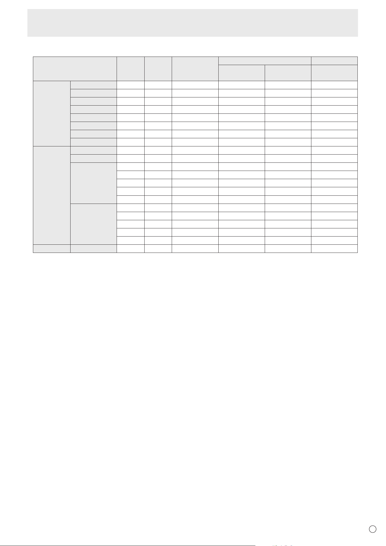
59
E
n
Compatible signal timing (PC)
Screen resolution Hsync Vsync Dot frequency
Digital Analog
HDMI
USB-C
(DisplayPort)
D-SUB
VESA 640 × 480 31.5kHz 60Hz 25.175MHz Yes Yes Yes
800 × 600 37.9kHz 60Hz 40.0MHz Ye s Ye s Ye s
1024 × 768 48.4kHz 60Hz 65.0MHz Yes Yes Yes
1280 × 960 60.0kHz 60Hz 108.0MHz Yes Yes Yes
1280 × 1024 64.0kHz 60Hz 108.0MHz Ye s Ye s Ye s
1360 × 768 47.7kHz 60Hz 85.5MHz Yes Yes Yes
1440 × 900 55.9kHz 60Hz 106.5MHz Yes Yes Yes
1680 × 1050 65.3kHz 60Hz 146.25MHz Ye s Ye s Ye s
Wide 1280 × 720 44.7kHz 60Hz 74.4MHz Ye s Ye s Ye s
1920 × 1080 67.5kHz 60Hz 148.5MHz Ye s Ye s Ye s
3840 × 2160 54.0kHz 24Hz 297.0MHz Ye s Ye s -
56.25kHz 25Hz 297.0MHz Yes Yes -
67.5kHz 30Hz 297.0MHz Yes Yes -
112.5kHz 50Hz 594.0MHz Yes Yes -
135.0kHz 60Hz 594.0MHz Yes Yes -
4096 × 2160 54.0kHz 24Hz 297.0MHz Ye s Ye s -
56.0kHz 25Hz 297.0MHz Yes Yes -
67.0kHz 30Hz 297.0MHz Yes Yes -
112.5kHz 50Hz 594.0MHz Yes Yes -
135.0kHz 60Hz 594.0MHz Yes Yes -
US TEXT 720 × 400 31.5kHz 70Hz 28.3MHz Ye s Ye s Ye s
• Depending on the connected computer, images may not be displayed properly even if the compatible signal described above is input.
Specifications
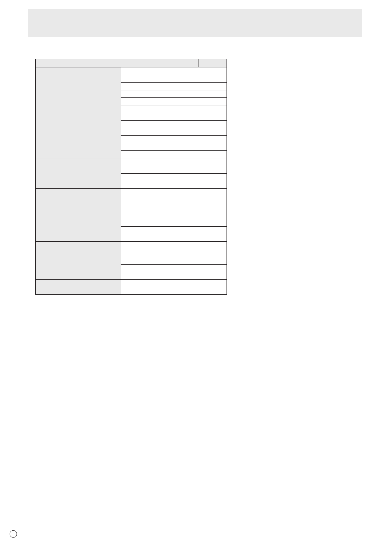
60
E
n
Compatible signal timing (AV)
Screen resolution Frequency HDMI USB-C
4096 × 2160p 24Hz Yes
25Hz Yes
30Hz Yes
50Hz Yes
59.94Hz Yes
60Hz Yes
3840 × 2160p 24Hz Yes
25Hz Yes
30Hz Yes
50Hz Yes
59.94Hz Yes
60Hz Yes
1920 × 1080p 24Hz Yes
50Hz Yes
59.94Hz Yes
60Hz Yes
1920 × 1080i 50Hz Yes
59.94Hz Yes
60Hz Yes
1280 × 720p 50Hz Yes
59.94Hz Yes
60Hz Yes
720 × 576p 50Hz Yes
720 × 480p 59.94Hz Yes
60Hz Yes
640 × 480p(VGA) 59.94Hz Yes
60Hz Yes
720(1440) × 576i 50Hz Yes
720(1440) × 480i 59.94Hz Yes
60Hz Yes
n
DDC (plug and play)
The monitor supports the VESA DDC (Display Data Channel) standard.
DDC is a signal standard for plug and play between monitors and computers. Information about resolution and other parameters
is exchanged between the two. This function can be used if the computer supports DDC and it has been configured to detect
plug-and-play monitors.
There are several types of DDC, depending on the communication method used. This monitor supports DDC2B.
Specifications

61
E
n
Channels that can be used in wireless LAN
Standard Channel
Frequency band
(center frequency)
IEEE802.11ax/n/g/b 1-11ch 2412-2462MHz
IEEE802.11ax/ac/n/a 36/40/44/48ch 5180-5240MHz
52/56/60/64ch 5260-5320MHz
100/104/108/112/116ch 5500-5580MHz
132/136/140ch 5660-5700MHz
149/153/157/161ch 5745-5805MHz
165ch 5825MHz
This device is restricted to indoor use due to its operation in the 5.15 GHz to 5.25 GHz frequency range. FCC requires this product to be used
indoors for frequency range 5.15 GHz to 5.25 GHz to reduce the potential for harmful interference to co-channel Mobile Satellite systems.
High power radars are allocated as primary users of the 5.25 GHz to 5.35 GHz and 5.65 GHz to 5.85 GHz bands. These radar stations can
cause interference with and/or damage this device.
Specifications

62
E
n
Information on the software license for this product
Software composition
The software included in this product is comprised of various software components whose individual copyrights are held by
SHARP or by third parties.
Software developed by SHARP and open source software
The copyrights for the software components and various relevant documents included with this product that were developed or
written by SHARP are owned by SHARP and are protected by the Copyright Act, international treaties, and other relevant laws.
This product also makes use of freely distributed software and software components whose copyrights are held by third parties.
These include software components covered by a GNU General Public License (hereafter GPL), a GNU Lesser General Public
License (hereafter LGPL) or other license agreement.
Obtaining source code
Some of the open source software licensors require the distributor to provide the source code with the executable software
components. GPL and LGPL include similar requirements. For information on obtaining the source code for the open source
software and for obtaining the GPL, LGPL, and other license agreement information, visit the following website:
https://jp.sharp/business/lcd-display/support/download/source_e.html
We are unable to answer any questions about the source code for the open source software. The source code for the software
components whose copyrights are held by SHARP is not distributed.
Intellectual Property Rights and Other Matters
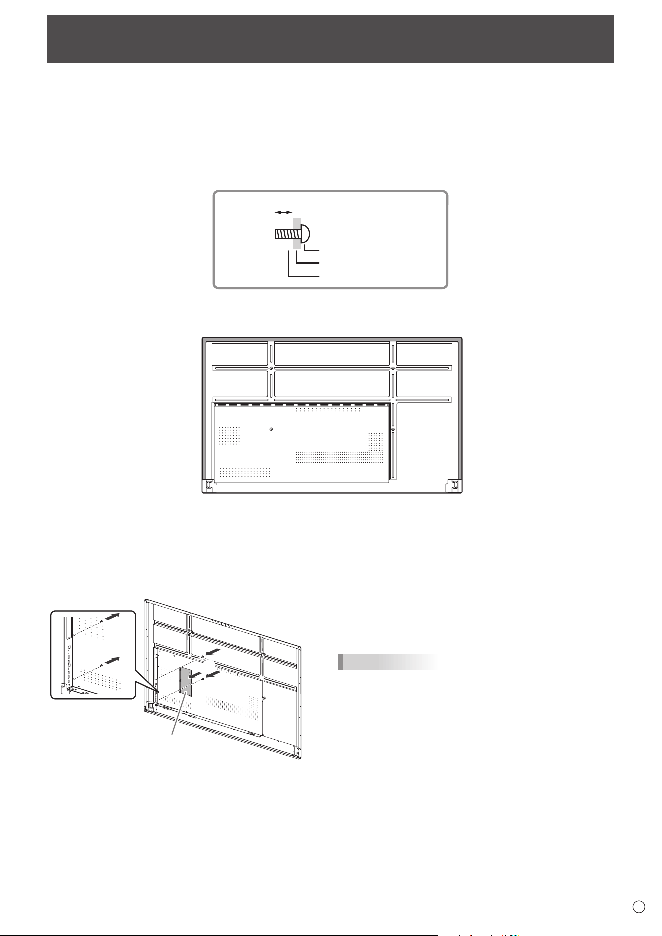
63
E
• When installing, removing or moving the monitor, ensure that this is carried out by at least 4 people. (PN-L652B: at least 2
people.)
• Be sure to use a wall-mount bracket designed or designated for mounting the monitor.
• This monitor is designed to be installed on a concrete wall or pillar. Reinforced work might be necessary for some materials
such as plaster / thin plastic board / wood before starting installation.
• This monitor and bracket must be installed on a wall which can endure at least 4 times or more the weight of the monitor.
Install by the most suitable method for the material and the structure.
• To attach a VESA-compliant mounting bracket, use M8 screws that are 3/8 inch (10 mm) to 1/2 inch (12 mm) longer than the
thickness of the mounting bracket.
Screws (M8)
Mounting bracket
Monitor mounting
3/8 - 1/2 inch (10-12 mm)
• Do not use an impact driver.
• When moving the monitor, be sure to hold the areas shown in the figure below. Do not grasp the screen. This may cause
product damage, failure, or injury.
• If you need to temporarily place the monitor on a table or other surface during installation, spread a thick soft cloth on the
table to prevent damage to the screen and table.
• After mounting, please carefully ensure the monitor is secure, and not able to come loose from the wall or mount.
• Do not use any screw holes other than those for mounting brackets, located on the rear of the monitor, for installation.
Mounting Precautions
(For SHARP dealers and service engineers)
n
Attaching player mount
Attach the player mount when installing an optional controller.
1
2
Player mount
1. Remove the screws from this monitor.
2. Attach the player mount with the player mount screws
(M3x6) (supplied) (x2).
TIPS
• Store the removed screws.
After removing the player mount, put back the removed
screws.

PN-L862B-L752B-L652B Mu EN22B(3)

