
PN-L501C
LCD MONITOR
OPERATION MANUAL

IMPORTANT:
To aid reporting in case of loss or theft, please record the
product’s model and serial numbers in the space provided.
The numbers are located in the rear of the product.
Model No.:
Serial No.:
U.S.A. ONLY
3
E
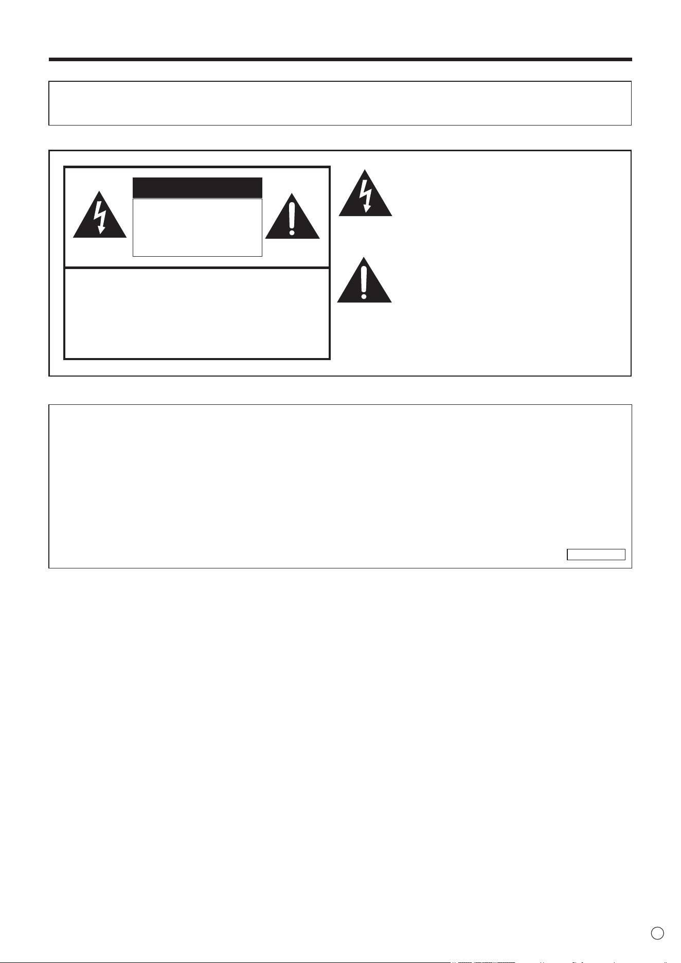
IMPORTANT INFORMATION
WARNING: TO REDUCE THE RISK OF FIRE OR ELECTRIC SHOCK, DO NOT EXPOSE THIS PRODUCT
TO RAIN OR MOISTURE.
RISK OF ELECTRIC
SHOCK
DO NOT OPEN
CAUTION
CAUTION: TO REDUCE THE RISK OF ELECTRIC
SHOCK, DO NOT REMOVE COVER.
NO USER-SERVICEABLE PARTS
INSIDE.
REFER SERVICING TO QUALIFIED
SERVICE PERSONNEL.
The lightning ash with arrowhead symbol, within
a triangle, is intended to alert the user to the
presence of uninsulated “dangerous voltage”
within the product’s enclosure that may be of
sufcient magnitude to constitute a risk of electric
shock to persons.
The exclamation point within a triangle is
intended to alert the user to the presence of
important operating and maintenance (servicing)
instructions in the literature accompanying the
product.
WARNING:
FCC Regulations state that any unauthorized changes or modications to this equipment not expressly approved by the
manufacturer could void the user’s authority to operate this equipment.
NOTE:
This equipment has been tested and found to comply with the limits for Class A digital device, pursuant to Part 15 of the
FCC Rules. These limits are designed to provide reasonable protection against harmful interference when the equipment
is operated in a commercial environment. This equipment generates, uses, and can radiate radio frequency energy and, if
not installed and used in accordance with the instruction manual, may cause harmful interference to radio communications.
Operation of this equipment in a residential area is likely to cause harmful interference in which case the user will be required
to correct the interference at his own expense.
U.S.A. ONLY

4
E
Thank you for your purchase of a SHARP LCD product. To ensure safety and many years of trouble-free operation of your
product, please read the Safety Precautions carefully before using this product.
SAFETY PRECAUTIONS
Electricity is used to perform many useful functions, but it can also cause personal injuries and property damage if improperly
handled. This product has been engineered and manufactured with the highest priority on safety. However, improper use can
result in electric shock and/or re. In order to prevent potential danger, please observe the following instructions when installing,
operating and cleaning the product. To ensure your safety and prolong the service life of your LCD product, please read the
following precautions carefully before using the product.
1. Read instructions — All operating instructions must be read and understood before the product is operated.
2. Keep this manual in a safe place — These safety and operating instructions must be kept in a safe place for future
reference.
3. Observe warnings — All warnings on the product and in the instructions must be observed closely.
4. Follow instructions — All operating instructions must be followed.
5. Cleaning — Unplug the power cord from the AC outlet before cleaning the product. Use a dry cloth to clean the product. Do
not use liquid cleaners or aerosol cleaners. Do not use dirty cloths. Doing so may damage the product.
6. Attachments — Do not use attachments not recommended by the manufacturer. Use of inadequate attachments can result
in accidents.
7. Water and moisture — Do not use the product near water. Do not install the product in a place where water may splash onto
it. Be careful of equipment which drains water such as an air-conditioner.
8. Ventilation — The vents and other openings in the cabinet are designed for ventilation.
Do not cover or block these vents and openings since insufcient ventilation can cause overheating and/or shorten the life
of the product. Do not place the product on a sofa, rug or other similar surface, since they can block ventilation openings.
Do not place the product in an enclosed place such as a bookcase or rack, unless proper ventilation is provided or the
manufacturer’s instructions are followed.
9. Power cord protection — The power cords must be routed properly to prevent people from stepping on them or objects from
resting on them.
10. The screen used in this product is made of glass. Therefore, it can break when the product is dropped or applied with
impact. Be careful not to be injured by broken glass pieces in case the screen breaks.
11. Overloading — Do not overload AC outlets or extension cords. Overloading can cause re or electric shock.
12. Entering of objects and liquids — Never insert an object into the product through vents or openings. High voltage ows in
the product, and inserting an object can cause electric shock and/or short internal parts.
For the same reason, do not spill water or liquid on the product.
13. Servicing — Do not attempt to service the product yourself. Removing covers can expose you to high voltage and other
dangerous conditions. Request a qualied service person to perform servicing.
14. Repair — If any of the following conditions occurs, unplug the power cord from the AC outlet, and request a qualied service
person to perform repairs.
a. When the power cord or plug is damaged.
b. When a liquid was spilled on the product or when objects have fallen into the product.
c. When the product has been exposed to rain or water.
d. When the product does not operate properly as described in the operating instructions.
Do not touch the controls other than those described in the operating instructions. Improper adjustment of controls
not described in the instructions can cause damage, which often requires extensive adjustment work by a qualied
technician.
e. When the product has been dropped or damaged.
f. When the product displays an abnormal condition. Any noticeable abnormality in the product indicates that the product
needs servicing.
15. Replacement parts — In case the product needs replacement parts, make sure that the service person uses replacement
parts specied by the manufacturer, or those with the same characteristics and performance as the original parts. Use of
unauthorized parts can result in re, electric shock and/or other danger.
16. Safety checks — Upon completion of service or repair work, request the service technician to perform safety checks to
ensure that the product is in proper operating condition.
17. Wall mounting — When mounting the product on a wall, be sure to install the product according to the method
recommended by the manufacturer.
18. Heat sources — Keep the product away from heat sources such as radiators, heaters, stoves and other heat-generating
products (including ampliers).
DEAR SHARP CUSTOMER
5
E
SAFETY PRECAUTIONS (Continued)
19. Batteries — Incorrect use of batteries may cause the batteries to burst or ignite. A leaky battery may corrode the equipment,
dirty your hands or spoil your clothing. In order to avoid these problems, make sure to observe the precautions below:
• Use the specied batteries only.
• Install the batteries with due attention to the plus (+) and minus (-) sides of the batteries according to the instructions in the
compartment.
• Do not mix old and new batteries.
• Do not mix batteries of different types. Voltage specications of batteries of the same shape may vary.
• Replace an exhausted battery with a new one promptly.
• If you will not use the remote control for a long time, remove the batteries.
• If leaked battery uid gets on your skin or clothing, rinse immediately and thoroughly. If it gets into your eye, bathe your
eye well rather than rubbing and seek medical treatment immediately. Leaked battery uid that gets into your eye or your
clothing may cause a skin irritation or damage your eye.
20. Usage of the monitor must not be accompanied by fatal risks or dangers that, could lead directly to death, personal injury,
severe physical damage or other loss, including nuclear reaction control in nuclear facility, medical life support system, and
missile launch control in a weapon system.
21. Do not stay in contact with the parts of the product that become hot for long periods of time. Doing so may result in
low-temperature burns.
22. Do not modify this product.
WARNING:
This is a Class A product. In a domestic environment this product may cause radio interference in which case the user may
be required to take adequate measures.
An apparatus with CLASS I construction shall be connected to a MAIN socket outlet with a protective earthing connection.
To maintain compliance with EMC regulations, use shielded cables to connect to the following terminals: HDMI input terminal,
D-sub input terminal, DisplayPort input terminal and RS-232C input terminal.
If a monitor is not positioned in a sufciently stable location, it can be potentially hazardous due to falling. Many injuries,
particularly to children, can be avoided by taking simple precautions such as:
• Using xing devices like wall mount brackets recommended by the manufacturer.
• Only using furniture that can safely support the monitor.
• Ensuring the monitor is not overhanging the edge of the supporting furniture.
• Not placing the monitor on tall furniture (for example, cupboards or bookcases) without anchoring both the furniture and the
monitor to a suitable support.
• Not standing the monitors on cloth or other materials placed between the monitor and supporting furniture.
• Educating children about the dangers of climbing on furniture to reach the monitor or its controls.
• This equipment is not suitable for use in locations where children are likely to be present unsupervised.
Especially for child safety
- Don’t allow children to climb on or play with the monitor.
- Don’t place the monitor on furniture that can easily be used as steps, such as a chest of drawers.
- Remember that children can become excited while watching a program, especially on a “larger than life” monitor. Care
should be taken to place or install the monitor where it cannot be pushed, pulled over, or knocked down.
- Care should be taken to route all cords and cables connected to the monitor so that they cannot be pulled or grabbed by
curious children.

6
E
-
The TFT color LCD panel used in this monitor is made with
the application of high precision technology. However, there
may be minute points on the screen where pixels never light
or are permanently lit. Also, if the screen is viewed from an
acute angle there may be uneven colors or brightness. Please
note that these are not malfunctions but common phenomena
of LCDs and will not affect the performance of the monitor.
- Do not display a still picture for a long period, as this could
cause a residual image.
- Never rub or tap the monitor with hard objects.
- Please understand that SHARP CORPORATION bears no
responsibility for errors made during use by the customer or
a third party, nor for any other malfunctions or damage to this
product arising during use, except where indemnity liability is
recognized under law.
- This monitor and its accessories may be upgraded without
advance notice.
-
Do not use the monitor where there is a lot of dust, where humidity
is high, or where the monitor may come into contact with oil or
steam. Do not use in an environment where there are corrosive
gases (sulfur dioxide, hydrogen sulde, nitrogen dioxide, chlorine,
ammonia, ozone, etc.). As this could lead to re.
-
Ensure that the monitor does not come into contact with water
or other uids. Ensure that no objects such as paper clips or
pins enter the monitor as this could lead to re or electric shock.
- Do not place the monitor on top of unstable objects or in
unsafe places. Do not allow the monitor to receive strong
shocks or to strongly vibrate. Causing the monitor to fall or
topple over may damage it.
- Do not use the monitor near heating equipment or in places
where there is likelihood of high temperature, as this may
lead to generation of excessive heat and outbreak of re.
- Do not use the monitor in places where it may be exposed to
direct sunlight. Risk of cabinet deformation and failure if the
monitor is used in direct sunlight.
- Images cannot be rotated on this monitor.
When using in portrait orientation, you will need to prepare
appropriately orientated content in advance.
- The AC outlet shall be installed near the equipment and shall
be easily accessible.
- Please be sure to constantly remove dust and garbage that
has attached to the ventilation opening. If dust collects in the
ventilation opening or the inside of the monitor, it may lead to
excessive heat, outbreak of re, or malfunction.
Please request a cleaning of the inside of the monitor from
an authorized SHARP servicing dealer or service center.
- Do not touch the screen when the monitor power is turned
on, it will lead to a malfunction. When this occurs, turn the
monitor power off and then on.
- Do not operate the screen with a hard or pointed object such
as a ngernail or pencil.
- Depending on the application used, the touch pen may not
function.
- If another USB device is connected to the computer to which
the touch panel is connected, do not operate the USB device
during touch panel input. Input may not take place correctly.
- Do not allow a cable to come near the screen. This may
cause the touch panel to malfunction.
- Continuous operating time and warranty.
This product is designed for a maximum daily use of 16
hours. Continual use in excess of 16 hours per day is not
covered by the warranty.
The Power Cord
- Use only the power cord supplied with the monitor.
- Do not damage the power cord nor place heavy objects on
it, stretch it or over bend it. Also, do not add extension cords.
Damage to the cord may result in re or electric shock.
- Do not use the power cord with a power tap.
Adding an extension cord may lead to re as a result of
overheating.
- Do not remove or insert the power plug with wet hands.
Doing so could result in electric shock.
- Unplug the power cord if it is not used for a long time.
- Do not attempt to repair the power cord if it is broken
or malfunctioning. Refer the servicing to the service
representative.
Manual Scope
- Microsoft and Windows are either registered trademarks or
trademarks of Microsoft Corporation in the United States
and/or other countries.
- The terms HDMI and HDMI High-Denition Multimedia
Interface, and the HDMI Logo are trademarks or registered
trademarks of HDMI Licensing Administrator, Inc. in the
United States and other countries.
- DisplayPort is a registered trademark of Video Electronics
Standards Association.
- Adobe, Acrobat, and Acrobat Reader are either registered
trademarks or trademarks of Adobe Systems Incorporated in
the United States and/or other countries.
- RoomView, Crestron RoomView and Crestron Connected
are either trademarks or registered trademarks of Crestron
Electronics, Inc. in the United States and/or other countries.
- Intel, Celeron, and Intel Core are trademarks or registered
trademarks of Intel Corporation or its subsidiaries in the
U.S.A. and other countries.
- All other brand and product names are trademarks or
registered trademarks of their respective holders.
- Language of OSD menu used in this manual is English by
way of example.
- Illustrations in this manual may not exactly represent the
actual product or display.
- This manual assumes use in landscape orientation, except
where specically noted.
LED Backlight
● The LED backlight in this product has a limited lifetime.
* If the screen gets dark or does not turn on, it may be
necessary to replace the LED backlight.
* This LED backlight is exclusive to this product and must
be replaced by an authorized SHARP servicing dealer
or service center. Please contact an authorized SHARP
servicing dealer or service center for assistance.
TIPS AND SAFETY INSTRUCTIONS
7
E
MOUNTING PRECAUTIONS
• This product is for use indoors.
• A mounting bracket compliant with VESA specications is
required.
• Since the monitor is heavy, consult your dealer before
installing, removing or moving the monitor.
• Mounting the monitor on the wall requires special expertise
and the work must be performed by an authorized SHARP
dealer. You should never attempt to perform any of this
work yourself. Our company will bear no responsibility
for accidents or injuries caused by improper mounting or
mishandling.
• Use the monitor with the surface perpendicular to a level
surface. If necessary, the monitor may be tilted up to 20
degrees upward.
• When moving the monitor, be sure to hold it around the
periphery. Do not grasp the screen or tray. This may cause
product damage, failure, or injury.
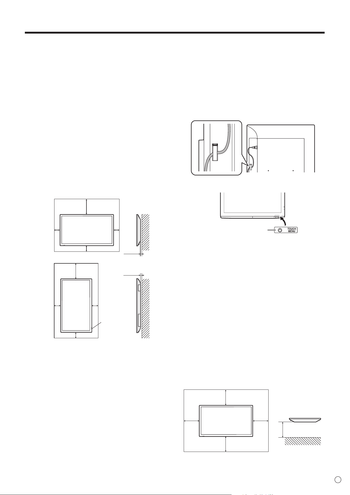
• This monitor should be used at an ambient temperature
between 41°F (5°C) and 95°F (35°C). Provide enough
space around the monitor to prevent heat from
accumulating inside.
Unit: inch [mm]
For the monitor in portrait orientation
7-7/8 [200]
2
[50]
2
[50]
2 [50]
2
[50]
2 [50]
For the monitor in landscape orientation
Unit: inch [mm]
5/16 [7]
5/16 [7]
7-7/8 [200]
2
[50]
Power LED
• If it is difcult to provide sufcient space for any reason
such as the installation of the monitor inside a housing, or
if the ambient temperature may be outside of the range
of 41°F (5°C) to 95°F (35°C), install a fan or take other
measures to keep the ambient temperature within the
required range.
• When installing two or more monitor units side-by-side,
provide space of at least 3/16 inch (5 mm) around them
to prevent stress on the adjacent unit or structure due to
thermal expansion.
• Do not block any ventilation openings. If the temperature
inside the monitor rises, this could lead to a malfunction.
• Do not place the monitor on a device which generates heat.
• Adhere to the following when installing the monitor in its
portrait orientation. Failing to adhere to the following may
cause malfunctions.
- Install the monitor such that the power LED is located on
the bottom side.
- Set the PORTRAIT/LANDSCAPE INSTALL on the
MONITOR menu to PORTRAIT. (See page 28.)
- Be sure to clamp the power cord (supplied) by using the
supplied cable clamp (afxing type). When clamping the
power cord, take care not to stress the terminal of the
power cord. Do not bend the power cord excessively.
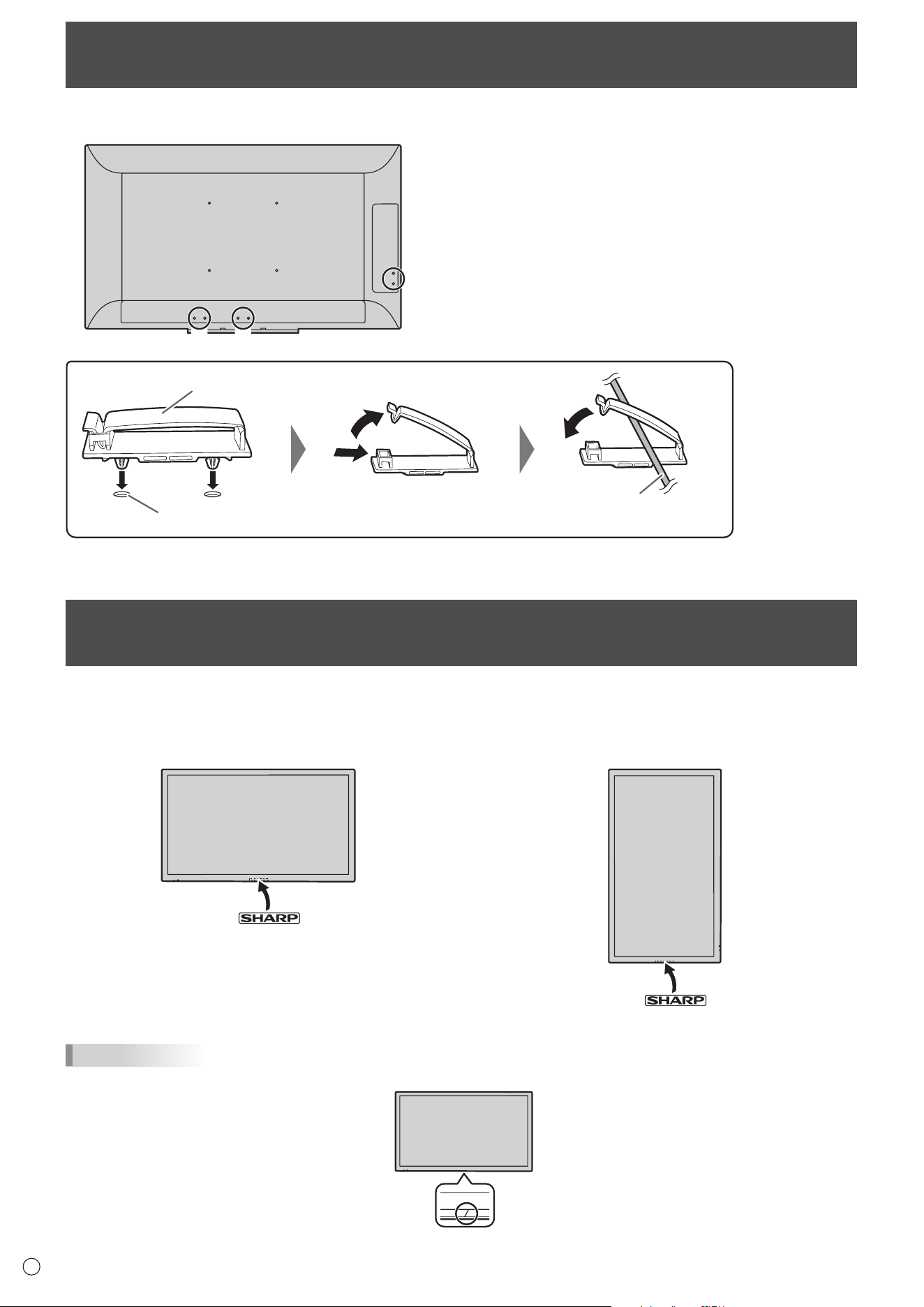
• Use the supplied vertical sticker when you install the
monitor in portrait orientation.
Operation panel
Flat installation
• When using the monitor laying at on a surface (when the
monitor is tilted more than 20 degrees upward from the
perpendicular in relation to a level surface), consult an
authorized SHARP dealer because there are some specic
mounting conditions. Adhere to the following. Failing to
adhere to the following may cause malfunctions.
- Set HORIZONTAL INSTALLATION in the MONITOR
menu to UPWARD. (See page 28.)
- Use the monitor at the ambient temperature within the
range of 41°F (5°C) to 86°F (30°C). Provide 7-7/8 inch
(200 mm) or more space between the monitor and the
oor or other mounting surfaces and surrounding objects
to prevent heat from accumulating inside. If it is difcult
to provide sufcient space or if the ambient temperature
may be outside of the range of 41°F (5°C) to 86°F (30°C),
install a fan or take other measures to keep the ambient
temperature within the required range.
- Do not press hard on the LCD panel or otherwise subject
it to impacts.
Unit: inch [mm]
Flat installation (UPWARD)
7-7/8 [200]
7-7/8 [200]
7-7/8
[200]
7-7/8
[200]
7-7/8
[200]

8
E
Contents
IMPORTANT INFORMATION ............................................ 3
DEAR SHARP CUSTOMER ..............................................4
SAFETY PRECAUTIONS ..................................................4
TIPS AND SAFETY INSTRUCTIONS ...............................6
MOUNTING PRECAUTIONS ............................................7
Supplied Components ..................................................... 9
System Requirements .....................................................9
Part Names .....................................................................10
Connecting Peripheral Equipment ...............................12
Connecting the Power Cord .........................................13
Binding Cables ............................................................... 14
Attaching the logo sticker ............................................. 14
Preparing the Remote Control Unit .............................. 15
Installing the batteries ................................................15
Remote control operation range .................................15
Mounting a web camera ................................................16
Turning Power On/Off .................................................... 17
Turning on the main power.........................................17
Turning power on/off ..................................................17
Basic Operation .............................................................18
Touch action ................................................................... 21
Touch action modes ...................................................21
Touch action ...............................................................21
Other functions ...........................................................23
Cautionary points .......................................................24
Eraser ......................................................................... 24
Menu Items .....................................................................25
Displaying the menu screen ....................................... 25
Menu item details .......................................................26
Adjustments for computer screen display ..................30
Controlling the Monitor with a computer (RS-232C)
...31
Computer connection .................................................31
Communication conditions .........................................31
Communication procedure .........................................31
RS-232C command table ........................................... 33
Controlling the Monitor with a computer (LAN) .......... 36
Settings to connect to a LAN ......................................36
Crestron Connected ...................................................37
Command-based control ............................................ 38
Troubleshooting .............................................................39
Specications ...............................................................41
Information on the software license for this product
...46
Mounting Precautions
(For SHARP dealers and service engineers) ............... 48
For information on the Pen Software, Information Display Downloader or SHARP Display Connect, see the manual for each.
9
E
Supplied Components
If any component should be missing, please contact your dealer.
System Requirements
Computer
PC/AT compatible computer able to output a resolution of 1920 x 1080.
(CD-ROM drive required for software installation.)
Operating system
Windows 7 (32-bit or 64-bit version), Windows 8.1 (32-bit or 64-bit version),
Windows 10 (32-bit or 64-bit version)
CPU
Intel Celeron B810E 1.6 GHz or faster
Intel Core i7-3517UE 1.7 GHz or faster recommended
Memory At least 2 GB
Free space on hard drive At least 5 GB (free space separately required for data storage)
To use the touch panel, connect the USB cable (supplied) to your computer.
Pen Software can be installed from the supplied CD-ROM.
When the Information Display Downloader is installed, you can check and download the most recent versions of the software
programs.
To install and use the software, see the manual for each.
Download the setup program for the SHARP Display Connect and Touch Viewer with the Information Display Downloader.
Liquid Crystal Display Monitor: 1
Remote control unit: 1
Cable clamp: 3
Power cord: 1
Remote control unit battery
(LR03 (“AAA” size)): 2
CD-ROM (Utility Disk): 1
SHARP Display Connect License: 1
Setup Manual: 1
Touch pen: 1
Tray: 1
Tray mounting screw/
camera mount screw (M3) : 2 each
USB cable: 1
Camera mount: 1
Camera screw (inch thread): 1
Logo sticker: 1
Vertical sticker (Operation panel): 1
* SHARP Corporation holds authorship rights to the Utility Disk program. Do not reproduce it without permission.
* For environmental protection!
Do not dispose of batteries in household waste. Follow the disposal instructions for your area.
10
E
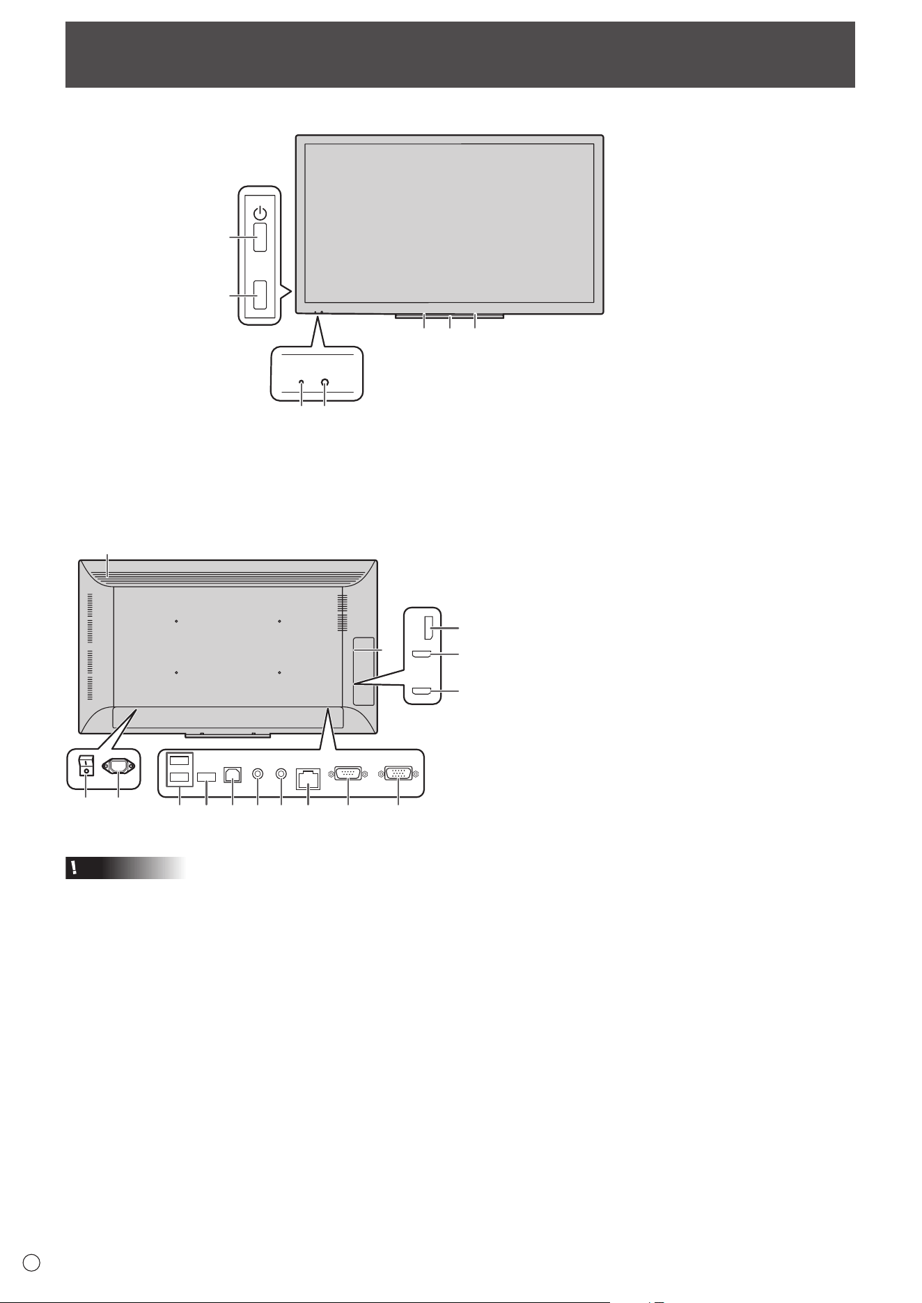
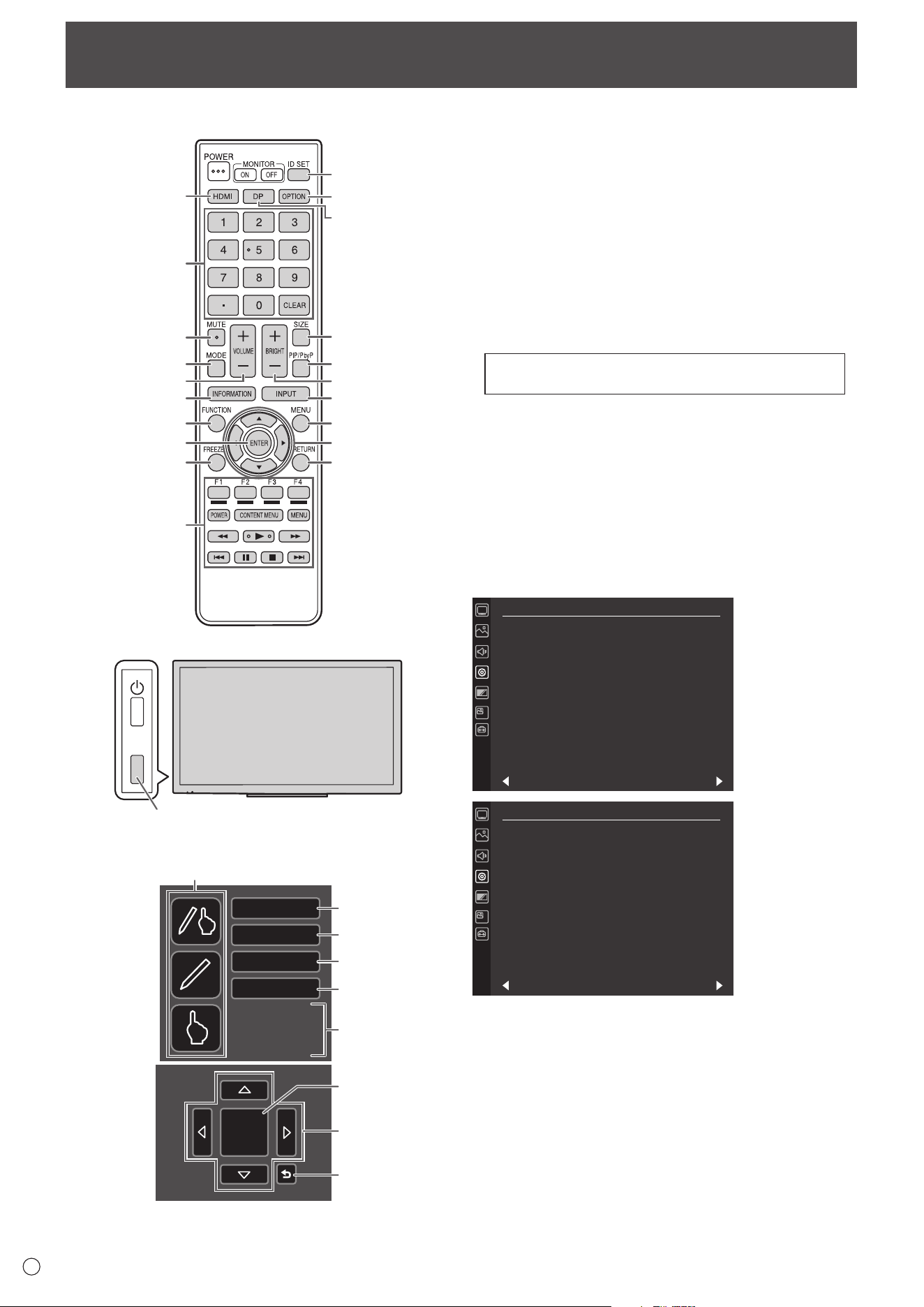
Part Names
n
Front view
TOUCH
MENU
2
556
1
3
4
n
Rear view
7
8 9
10 * 11 12 13 15 1614
17
18
19
20
1. Power LED (See page 17.)
2. Remote control sensor (See page 15.)
3. POWER button (See page 17.)
7. Vents
8. Main power switch (See page 17.)
9. AC input terminal (See page 13.)
10. USB port (See page 13.)
11. USB port (for touch panel) (See page 13.)
12. Audio output terminal (See page 12.)
13. Audio input terminal (See page 12.)
14. LAN terminal (See page 12.)
15. RS-232C input terminal (See page 12.)
16. D-sub input terminal (See page 12.)
17. DisplayPort input terminal (See page 12.)
18. HDMI1 input terminal (See page 12.)
19. HDMI2 input terminal (See page 12.)
20. Expansion slot
This section is used to connect optional hardware
for function expansion. (Offering this attachment
location is not a guarantee that future compatible
hardware attachments will be released.)
* Terminal for rmware updating
Normally not used.
4. TOUCH MENU button (See page 18.)
5. Speakers
6. Tray (See page 48.)
Caution
• Consult your SHARP dealer for attachment/detachment of
optional parts.
11
E
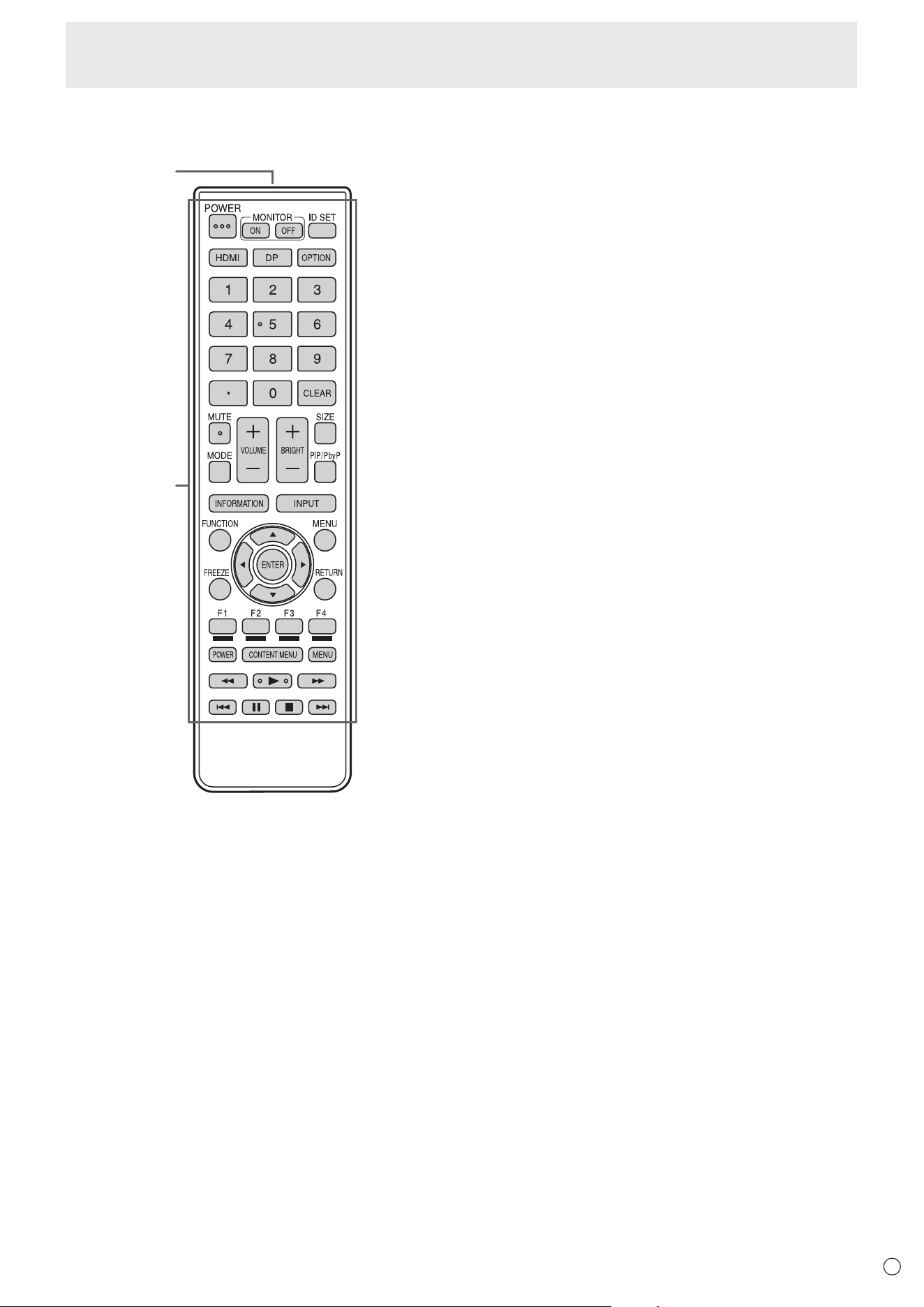
Part Names
2
1
1. Signal transmitter
2. Operation buttons (See pages 18 and 19.)
n
Remote control unit
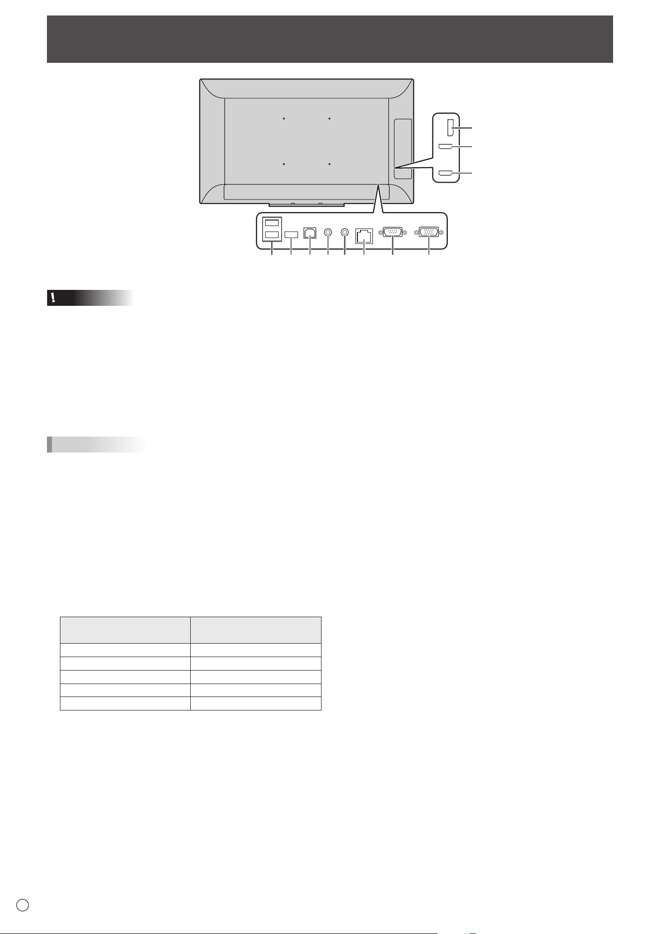
12
E
Connecting Peripheral Equipment
Caution
• Be sure to turn off the main power switch and disconnect
the plug from the power outlet before connecting/
disconnecting cables. Also, read the manual of the
equipment to be connected.
• Be careful not to confuse the input terminal with the output
terminal when connecting cables. Accidentally reversing
cables connected to the input and output terminals may
cause malfunctions and the other problems.
• Do not use any cable that has a damaged or deformed
terminal. Using such cables may cause malfunctions.
TIPS
•
When using the touch panel, connect the USB cable to the
computer.
• Images may not be displayed properly depending on the
computer (video card) to be connected.
• If the audio output from the playback device is connected
directly to speakers or other devices, the video on the
monitor may appear delayed from the audio portion.
Audio should be played through this monitor by connecting
the playback device to the monitor’s audio input, and
connecting the monitor’s audio output to the speakers or
other devices.
• The audio input terminals used in each input mode are
factory-set as follows.
Input mode
Audio input terminal
(Factory setting)
DisplayPort DisplayPort input terminal
HDMI1 HDMI1 input terminal
HDMI2 HDMI2 input terminal
D-SUB Audio input terminal
OPTION * Expansion slot
* When you have used the expansion slot to expand the
functions.
1. HDMI1 input terminal
2. HDMI2 input terminal
• Use a commercially available HDMI cable (conforming to
the HDMI standard).
• Select the audio input terminal to be used in AUDIO
SELECT of the AUDIO menu. When HDMI1 or HDMI2
is selected, connection to the audio input terminal is
unnecessary.
3. DisplayPort input terminal
• Use a commercially available DisplayPort cable
(conforming to the DisplayPort standard).
•
Select the audio input terminal to be used in AUDIO
SELECT of the AUDIO menu. When DisplayPort is selected,
connection to the audio input terminal is unnecessary.
4. D-sub input terminal
5. Audio input terminal
• Use an audio cable without resistance.
6. RS-232C input terminal
• You can control the monitor from a computer by
connecting a commercially available RS-232 straight
cable between this terminal and the computer.
7. Audio output terminal
• The output sound varies depending on the input mode.
8. LAN terminal
• You can control the monitor from a computer on a network
by connecting a commercially available LAN cable
between this terminal and a network.
2
46857910 *
1
3
13
E
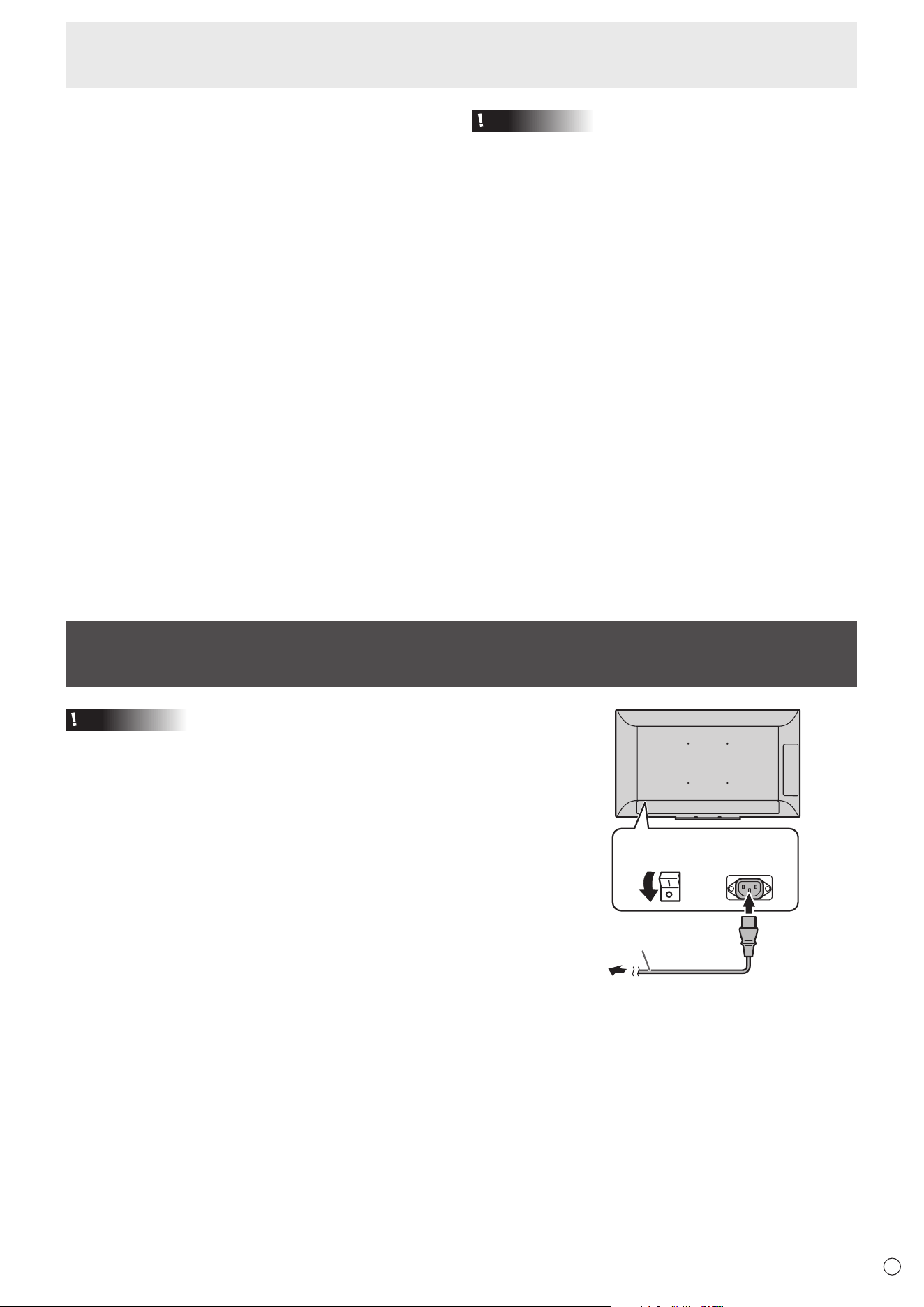
Connecting the Power Cord
Caution
• Use only the power cord supplied with the monitor.
1. Turn off the main power switch.
2. Plug the power cord (supplied) into the AC input terminal.
3. Plug the power cord (supplied) into the AC power outlet.
Main power
switch
Power cord (Supplied)
2
1
AC input
terminal
For power
outlet
3
Connecting Peripheral Equipment
Caution
Precautions when a USB storage device (USB ash drive,
USB hard disk, etc.) is used
• When USB PORT SELECTION in the SETUP menu is
AUTO and the input mode is changed to OPTION, the USB
and touch panel connection changes to the expansion slot
device.
When the input mode is changed from OPTION, the
USB and touch panel connection changes to a computer
connected to this monitor’s USB port (for touch panel).
• Data may be corrupted if the connection is switched while a
USB storage device is being accessed.
When connecting a USB storage device, set USB PORT
SELECTION to EXTERNAL or OPTION depending on the
connected device to x the connection.
Or, set to MANUAL, change the input mode, and then make
sure the USB storage device is not being accessed before
switching the connection manually.
9. USB port (for touch panel)
• To use the touch panel, connect to your computer with the
provided USB cable.
10. USB port
• Can be used as a USB hub (USB 2.0 compliant) of the
computer that is connected to the USB port (for touch
panel).
• When the monitor power is ON, USB power can be
supplied.
When RESUME BY TOUCH is set to ON, USB power can
also be supplied in the input signal waiting mode.
• When a function is added using the expansion slot and
the input mode is set to OPTION, a USB device can
be used with the device in the expansion slot. (When
USB PORT SELECTION is set to a setting other than
EXTERNAL.)
When this is done, the USB device cannot be used with
the computer that is connected to the USB port (for touch
panel).
* Terminal for rmware updating
Normally not used.
14
E
The cables connected to the terminals on the rear of the monitor can be fastened with the supplied cable clamp.
Cable
Cable clamp
*
**
*
Affixing point
Attaching the logo sticker
Binding Cables
You can attach the supplied logo sticker on the monitor.
Landscape orientation
Portrait orientation
TIPS
• If the tray is not attached, you can see a center mark on the undersurface of monitor.
15
E
Preparing the Remote Control Unit
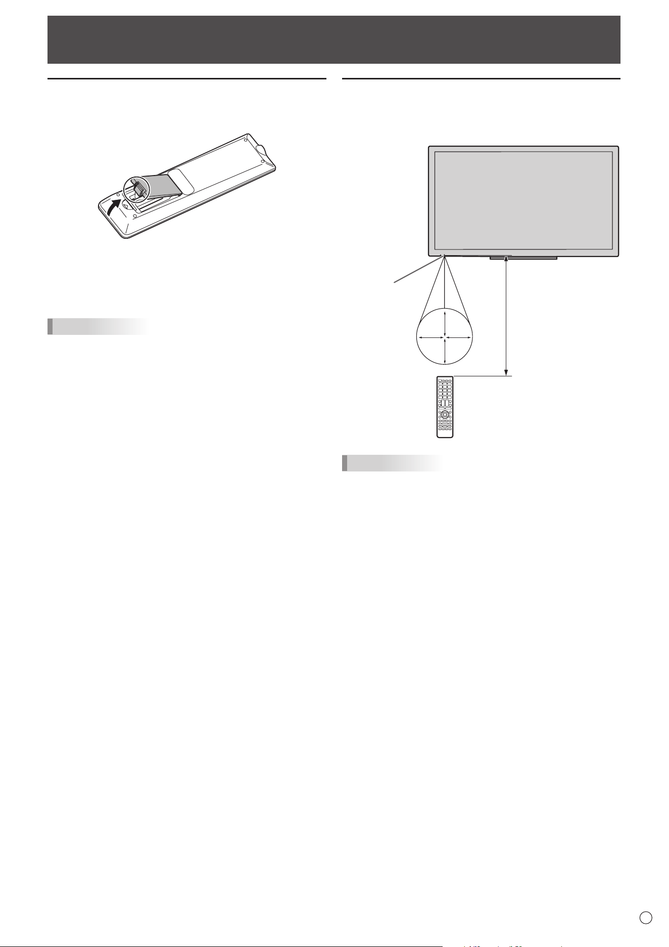
Installing the batteries
1. Placeyourngeronthepartmarkedwiththe▲,and
then pull the cover off.
2. Seetheinstructionsinthecompartmentandputinthe
batteries(LR03(“AAA”size)x2)withtheirplus(+)and
minus(-)sidesorientedcorrectly.
3. Close the cover.
TIPS
• Whenthebatteriesbecomeexhausted,replacethemwith
new(commerciallyavailable)batteries.
• Thesuppliedbatteries(LR03(“AAA”size)x2)maybecome
exhaustedquicklydependingonhowtheyarestored.
• Ifyouwillnotbeusingtheremotecontrolforalongtime,
removethebatteries.
• Usemanganeseoralkalinebatteriesonly.
Remote control operation range
Theoperationrangeoftheremotecontrolunitisapprox.16.4
feet(5m)atanangleofapprox10°fromthecentertothetop/
bottom/right/leftoftheremotecontrolsensor.
Remote control
sensor
10°10°
10°
10°
16.4
feet
(5 m)
TIPS
• Donotexposetheremotecontrolunittoshockbydropping
orsteppingonit.Thiscouldleadtoamalfunction.
• Donotexposetheremotecontrolunittoliquids,anddonot
placeitinanareawithhighhumidity.
• Theremotecontrolunitmaynotworkproperlyiftheremote
controlsensorisunderdirectsunlightorstronglighting.
• Objectsbetweentheremotecontrolunitandtheremote
controlsensormaypreventproperoperation.
• Replacethebatterieswhentheyrunlowasthismay
shortentheremotecontrol’soperationrange.
• Ifauorescentlightisilluminatedneartheremotecontrol
unit,itmayinterferewithproperoperation.
• Donotuseitwiththeremotecontrolofotherequipment
suchasairconditioner,stereocomponents,etc.
16
E
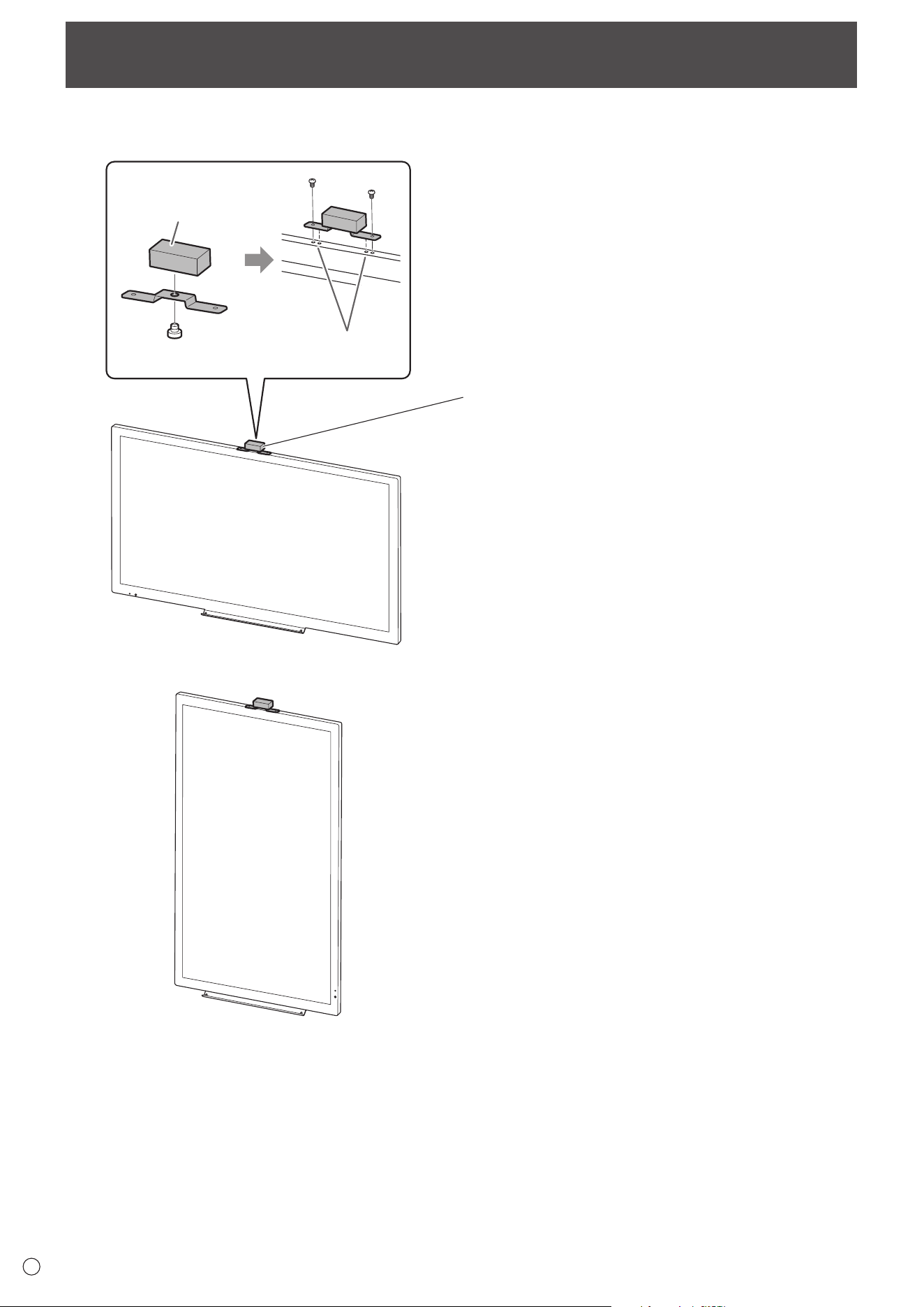
Mounting a web camera
12
Web camera
(commercially available)
Insert tab into
hole to secure
Landscape orientation
Portrait orientation
It is possible to mount a commercially available web camera in the following positions:
(1) Attach the web camera (commercially available) to the
camera mount with the supplied camera screw (inch
thread) (x1).
(2) Attach the supplied camera mount with the supplied
camera mount screws (x2).
17
E
Caution
• When all connections are complete, turn on the power.
• Turn on the monitor rst before turning on the computer or
playback device.
• When switching the main power switch or the POWER
button off and back on, always wait for at least 5 seconds.
A short interval may result in a malfunction.
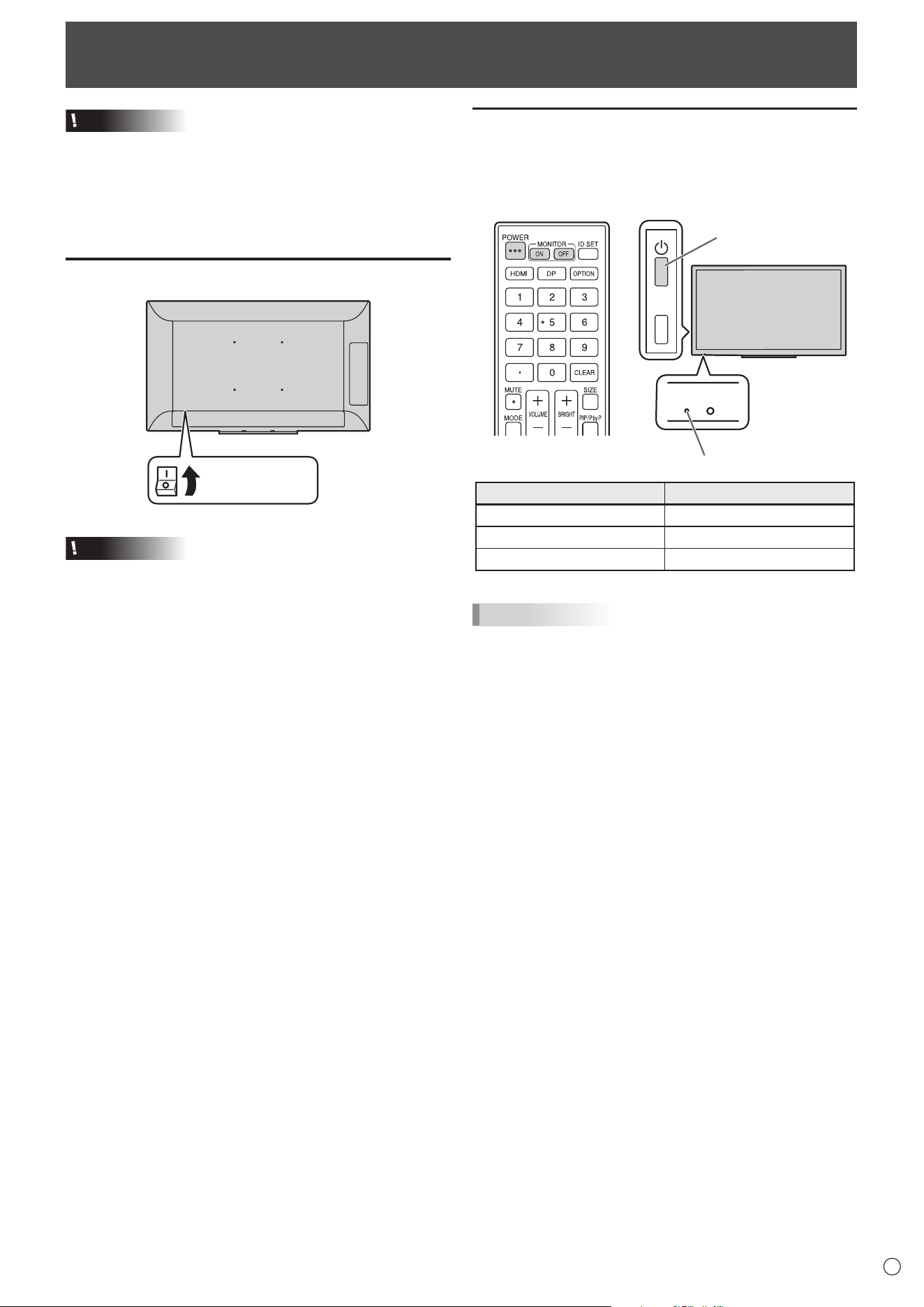
Turning on the main power
Main power switch
Caution
• The main power must be turned on/off with the main power
switch. Do not connect/disconnect the power cord or turn
the breaker on/off while the main power switch is on.
• For a complete electrical disconnection, pull out the main
plug.
Turning Power On/Off
Turning power on/off
Press the POWER button to turn the power ON/OFF.
You can also turn the power ON/OFF by pressing the
MONITOR ON button/MONITOR OFF button on the remote
control unit.
TOUCH
MENU
Power LED
POWER button
Status Status of the monitor
Green lit Power on
Orange lit Power off (Standby mode)
Green ashing Input signal waiting mode
TIPS
• When the main power switch is off, the monitor cannot be
turned on.
• If the monitor is in the input signal waiting mode and you
press the POWER button, the monitor enters standby
mode.
• To disable the logo screen from displaying when turning the
power ON, set LOGO SCREEN to OFF on the OTHERS
menu. (See page 29.)
18
E
Basic Operation
Remote control unit
1
2
3
4
5
6
7
8
9
10
11
12
13
14
15
16
17
18
19
20
Buttons on the monitor
TOUCH
MENU
TOUCH MENU button
Press the TOUCH MENU button to display the touch menu.
ENTER
24
HDMI1
HDMI2
DisplayPort
D-SUB
13
21
22
23
*
19
20
8
1. HDMI
Switch the input mode to HDMI1 or HDMI2.
2. Numeric input buttons
These are not used with this monitor.
3. MUTE
Turns off the volume temporarily.
Press the MUTE button again to turn the sound back to the
previous level.
4. MODE (Color mode selection)
Each time you press this button, the color mode changes in
the following order:
STD (PC) → HIGH ILLUMINANCE → AV → USER
→ STD (PC)...
• HIGH ILLUMINANCE is a display with colors suited to
bright locations.
5. VOLUME +/- (Volume adjustment)
Press + or - to display the volume menu and adjust the
volume.
* If you do not press any buttons for approx. 3 seconds, the
VOLUME menu automatically disappears.
6. INFORMATION
Displays monitor information.
INPUT MODE
SIZE
COLOR MODE
BRIGHT
VOLUME
MODEL
MAIN VER
LAN VER
TPC VER
S/N
STATUS
SIGNAL
:
:
:
:
:
:
:
:
:
:
:
:
INFORMATION
D-SUB
WIDE
STD (PC)
31
15
PN-L501C
X.X.X.X
X.XX
XX.XX
XXXXXXXX
0000-000000-00-0000
XXXXxXXXX XXXKHz XXHz
RS-232C/LAN SELECT
DHCP CLIENT
IP ADDRESS
SUBNET MASK
DEFAULT GATEWAY
MONITOR NAME
DATA PORT
MAC ADDRESS
:
:
:
:
:
:
:
:
INFORMATION
LAN
ON
000.000.000.000
000.000.000.000
0. 0. 0. 0
PN-L501C
10008
XX-XX-XX-XX-XX-XX
The display changes from INFORMATION1 →
INFORMATION2 → INFORMATION3 → clear display, and so
on every time you press this button.
Press the MENU button to hide the screen display.
• INFORMATION3 shows the information when you have
used the expansion slot to expand the functions.
• The display disappears automatically after approx. 60
seconds.
* When a function is added using the expansion slot, a
button for changing the input mode will appear.
19
E
7. FUNCTION
This is not used with this monitor.
8. ENTER
Conrms the setting.
9. FREEZE
Freezes the video shown on the monitor. To cancel, press any
button other than the MUTE button or VOLUME button.
10. Buttons for operating the HDMI-connected device
These are not used with this monitor.
11. ID SET
This is not used with this monitor.
12. OPTION
Switch the input mode to OPTION.
13. DP (DisplayPort)
Switch the input mode to DisplayPort.
14. SIZE (Screen size selection)
The menu is displayed.
Press the
or button to select the screen size. (See page
20.)
15. PIP/PbyP
The menu is displayed.
Press the
or button to select PIP MODES.
16. BRIGHT +/- (Brightness adjustment)
Press + or - to display the brightness menu and adjust the
brightness.
* If you do not press any buttons for approx. 3 seconds, the
BRIGHT menu automatically disappears.
17. INPUT (Input mode selection)
The menu is displayed. Press the
or button to select the
input mode, and press ENTER button to enter.
Input mode Video Audio
DisplayPort DisplayPort input terminal
*2
HDMI1 HDMI1 input terminal
HDMI2 HDMI2 input terminal
D-SUB D-sub input terminal
Audio input
terminal
OPTION
*1
Expansion slot
*2
*1 This is displayed when you have used the expansion slot
to expand the functions.
*2 Select the terminal for AUDIO SELECT of the AUDIO
menu which is used for audio input. (See page 27.)
18. MENU
Displays and turns off the menu screen. (See page 25.)
19. Cursor
These buttons are used to perform operations such as
selecting items, changing adjustment values, and moving the
cursor.
Basic Operation
20. RETURN
Returns to the previous screen.
21. HDMI1
Switch the input mode to HDMI1.
22. HDMI2
Switch the input mode to HDMI2.
23. D-SUB
Switch the input mode to D-SUB.
24. Touch mode selection
These icons switch the touch action mode. (See page 21.)
n
Switching of the USB and touch panel
connection
• Switching of the USB and touch panel connection when the
input mode is changed to or from OPTION depends on the
USB PORT SELECTION setting in the SETUP menu.
• When set to AUTO, the connection changes to the
expansion slot device or the computer connected to this
monitor’s USB port (for touch panel).
• When set to EXTERNAL/OPTION, the connection is xed
at the computer connected to this monitor’s USB port (for
touch panel) / expansion slot device and does not change.
• When set to MANUAL,
( ) appears when the
input is changed. (Approx. 5 seconds.)
Touch
( ) to change the connection.
If you are using a USB storage device, make sure it is not
being accessed before you switch.
If
( ) disappears, it will appear when the
screen is touched.
20
E
Basic Operation
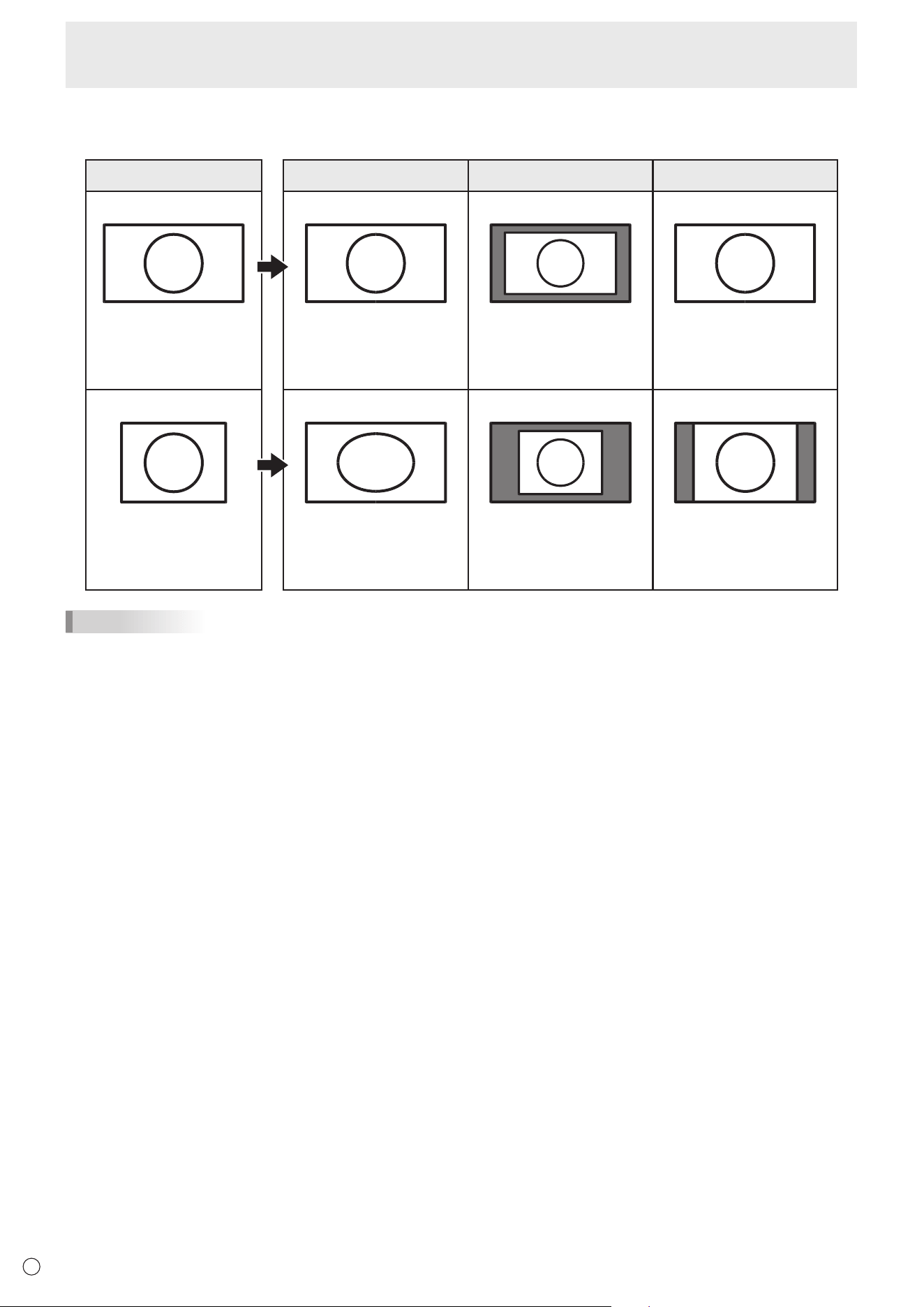
n
Switching the screen size
Even when the screen size is changed, the display may remain the same depending on the input signal.
INPUT SIGNAL WIDE Dot by Dot NORMAL
16:9 video
1920×1080,
1280×720 etc.
Displays image so it lls the
entire screen.
Displays the dots of
the input signals as the
corresponding dots on the
screen.
Displays image so it lls
the entire screen without
changing the aspect ratio of
the input signal.
Video other than 16:9
640×480,
800×600,
1024×768,
1280×1024 etc.
Displays image so it lls the
entire screen.
Displays the dots of
the input signals as the
corresponding dots on the
screen.
Displays image so it lls
the entire screen without
changing the aspect ratio of
the input signal.
TIPS
• Using this monitor’s screen-size switching to compress or expand the screen for commercial or public viewing in
establishments like cafes or hotels may infringe on the rights of the creators, as protected by Copyright Law, so please be
careful.
• The appearance of the original video may change if you select a screen size with a different aspect ratio than the original
image (e.g. TV broadcast or video input from external equipment).
• When 4:3 video is viewed with the whole screen using the screen-size switching function of this monitor, the edge of the video
may be lost or appear distorted. If you wish to respect the creator’s intentions, set the screen size to “NORMAL”.
• When playing commercial software, parts of the image (like subtitles) may be cropped. In this case select the optimal screen
size using the screen-size switching function of this monitor. With some software, there may be noise or distortion at the
edges of the screen. This is due to the characteristics of the software, and is not a malfunction.
• Depending on the original image size, black bands may remain at the edges of the screen.
21
E
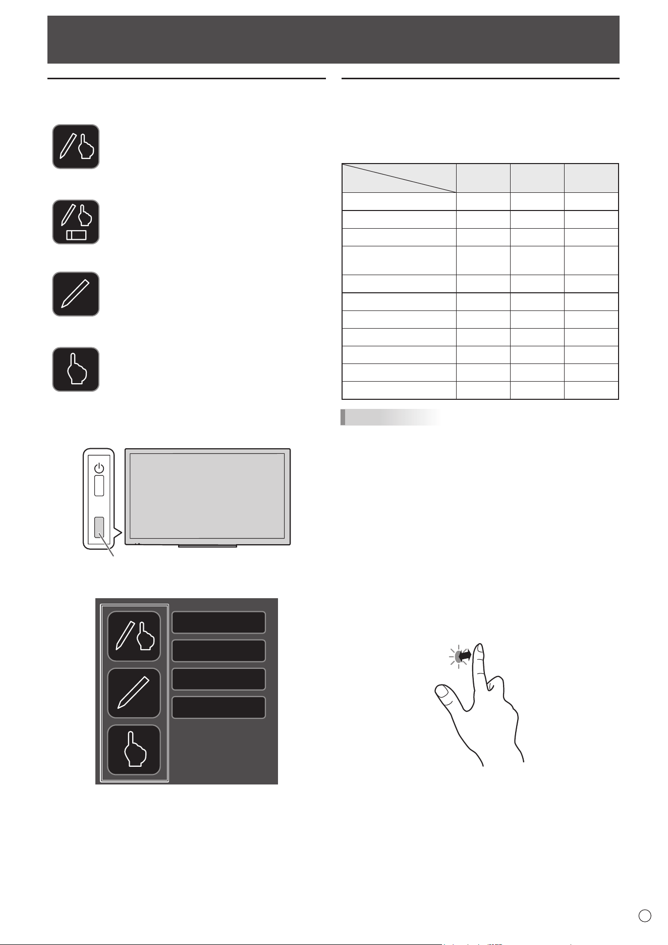
Touch action
Touch action modes
You can prohibit nger operation or pen operation.
Finger/pen mode
You can use both your nger and a pen.
When ERASER FUNCTION is set to OFF,
the eraser function (see page 24) cannot be
used.
When ERASER FUNCTION is set to ON,
the eraser function (see page 24) can be
used.
(Eraser icon will appear on the nger/pen
mode icon.)
Pen-only mode
You can use a pen.
You cannot use your nger.
The eraser function (see page 24) cannot be
used.
Finger-only mode
You can use your nger.
A pen cannot be used.
The eraser function (see page 24) cannot be
used.
1. Press the TOUCH MENU button.
TOUCH
MENU
TOUCH MENU button
2. Change the touch mode.
HDMI1
HDMI2
DisplayPort
D-SUB
Touch action
Touch actions that can be used with this monitor differ
according to operating system and application. The functions
of touch actions are also different. For details, check operating
system Help and the application’s support documentation.
Operating system
Touch action
Windows
8.1 / 10
Windows
7
Chrome
OS
Single-tap Yes Yes Yes
Double-tap Yes Yes Yes
Swipe Yes Yes Yes
Swipe from edge of
screen
Yes No Yes
Drag-and-drop Yes Yes Yes
Flicks Yes Yes Yes
Press-and-hold Yes Yes Yes
Slide to pan Yes Yes Yes
Zoom Yes Yes Yes
Press-and-tap No Yes Yes
Rotate Yes Yes Yes
TIPS
• In Windows 7, if the checkmark has been removed from
“Enable multi-touch gestures and inking” in “Pen and touch”
in Control Panel, select the checkbox.
• For the procedures for using the touch pen in the Pen
Software, see the Pen Software Operation Manual.
• We recommend using with following settings.
When you set items except for the following items, touch
action may occasionally deviate.
Input signal : 1920×1080
SIZE : Dot by Dot
n
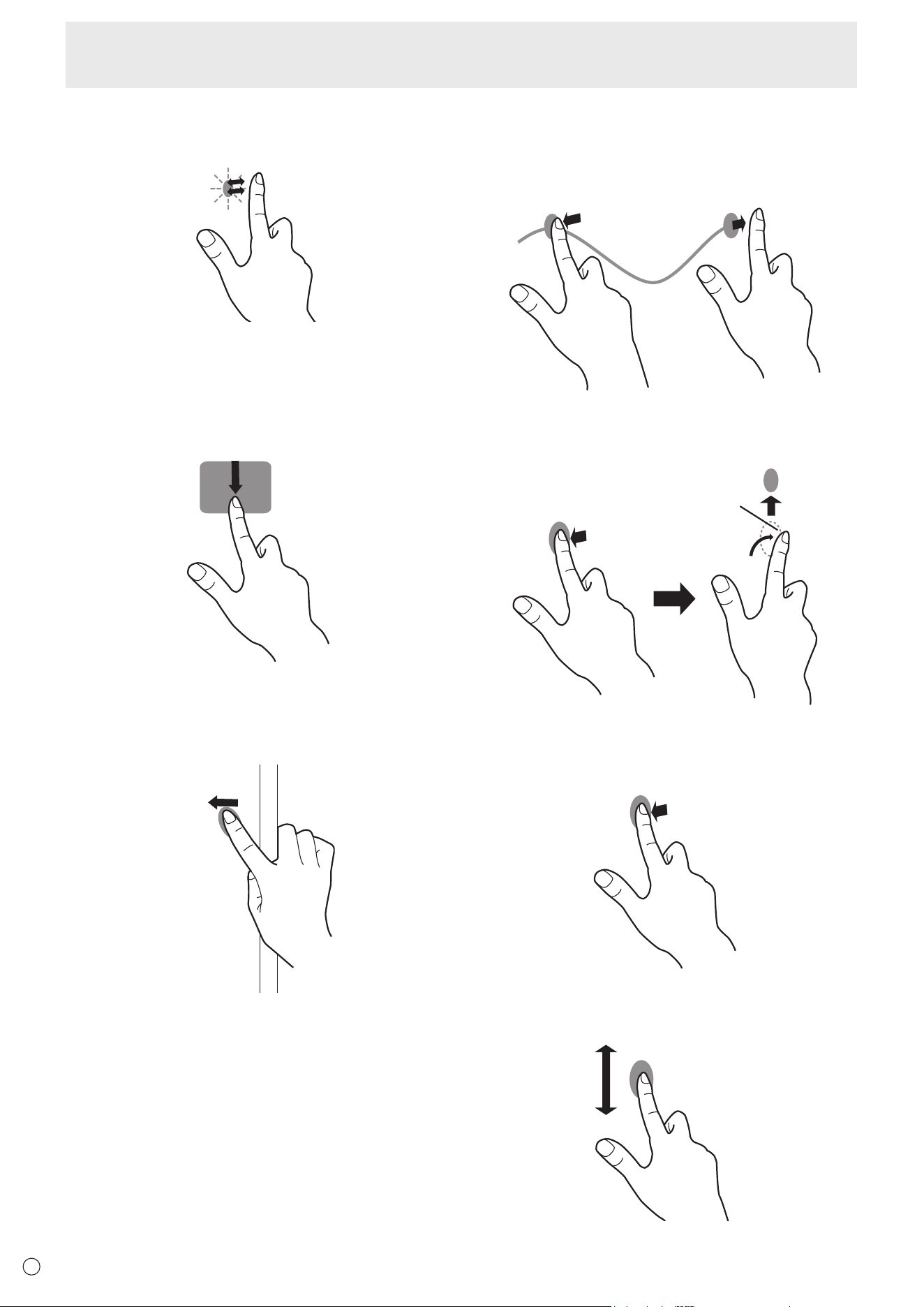
Common nger and touch pen actions
Single-tap
Same action as left-clicking a mouse.
Touch with your nger/touch pen.
22
E
Touch action
Double-tap
Same action as double-clicking a mouse.
Quickly touch twice with your nger/touch pen.
When double-tapping with your nger, be sure to lift your
nger sufciently off the screen after the rst tap. If there
is insufcient distance between the screen and your nger,
double-tap will not take place.
Swipe
Touch the screen with your nger/touch pen, move without
lifting, and then stop.
Swipe from edge of screen
After touching the edge of the monitor with your nger/touch
pen, move horizontally without releasing your nger/touch pen
and then stop.
Drag-and-drop
Same action as drag-and-drop with a mouse.
Touch the screen with your nger/touch pen and move without
lifting. When you have nished the movement, lift your nger/
touch pen.
Flicks
Flick your nger/touch pen in the direction of the function you
want to use.
Flick your nger
Press-and-hold
Same action as right-clicking a mouse.
Press briey with your nger/touch pen, and then lift your
nger/touch pen from the screen.
Slide to pan
With your nger/touch pen touching the screen, move it up
and down to scroll the screen.
23
E
Touch action
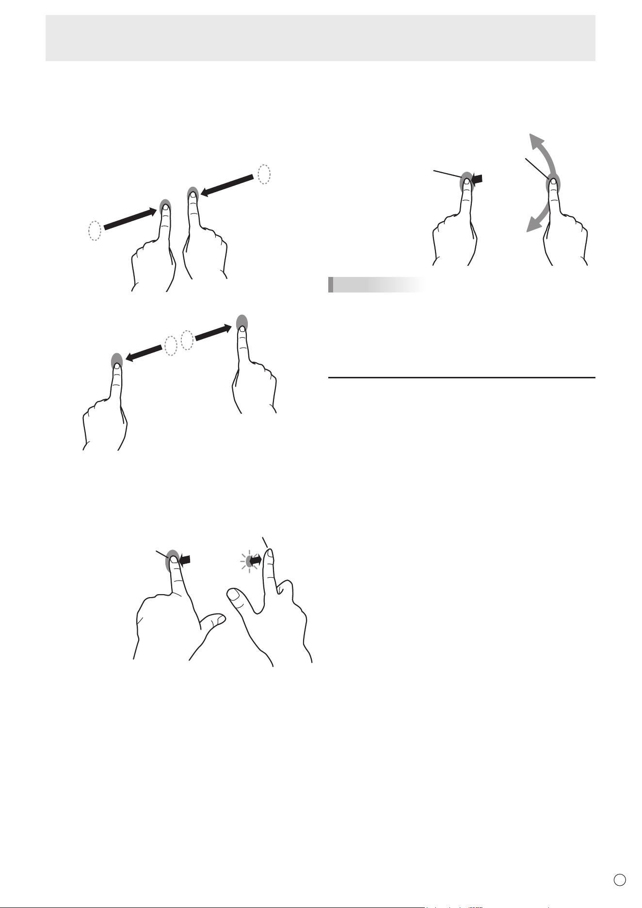
n
Finger actions
Zoom
Use in a screen that is capable of enlargement/reduction.
Touch the screen with two ngers and move your ngers
closer together to reduce the view, or apart to enlarge the
view.
Reduction
Enlargement
Press-and-tap
Same action as right-clicking a mouse.
With one nger touching the screen, tap once (single tap) with
another nger.
With one nger touching
Tap once (single tap) with another nger
Rotate
Use this action in a screen that is capable of image rotation.
Touch the center point of the rotation with one nger. While
holding that nger still, move another nger in the desired
direction of rotation.
With one nger touching
Move another nger in the
desired direction of rotation
TIPS
•
The screen may not respond correctly in the following cases:
Touch gesture is too quick
The distance between the two points is too short
The two points intersect
•
Operation with the touch pen is not possible.
Other functions
In Windows 8.1/10, input panel functions can be used.
In Windows 7, touch pointer and input panel functions can be
used.
For information on these functions, see Windows Help.
Touch pointer :
A translucent image of a mouse appears near the point
touched. The left/right buttons of the image can be clicked
to perform the same actions as left/right clicking a mouse.
Input panel :
A software keyboard and an input panel with handwriting
recognition appear on the screen.
Windows 8.1/10 and Windows 7 (excluding Starter), the ink
function of Microsoft Ofce can be used.
Handwritten comments can be written, and handwriting can
be recognized.
For details, see Microsoft Ofce Help.
24
E
Touch action
Cautionary points
• Notethefollowingwhentouchingbynger:
- Donottouchwithawetnger.
- Touchwiththeballofyournger.
- Touchwithyourbarenger.
Thescreenwillnotrespondifyouarewearingaglove.
• Donotusethetouchpenforanypurposeotherthantouch
paneloperation.
• Donotpresshardonthepentip.
• Ifthepentipbecomeswornordamaged,replacethetouch
pen.Topurchaseanewtouchpen,consultyourdealer.
• Drawingmaynotbeperformedcorrectlyduetothe
surroundingenvironment,suchaselectromagneticwaves.
• Thismaynotoperatecorrectlyifthereisaninverter
uorescentlightnearby.
• Ifthereisdirtorforeignmatteronthetipofthetouchpen,
removeit.Foreignmattermaydamagethescreen.
• Thetouchpenpositionmayoccasionallydeviateinthe
loginscreen.Inthiscase,usethekeyboardormouse.
• IftheUSBcablebecomesdisconnected,thetouch
panelmaynotoperatecorrectlyaftertheUSBcableis
reconnected.Inthiscase,restartthecomputer.
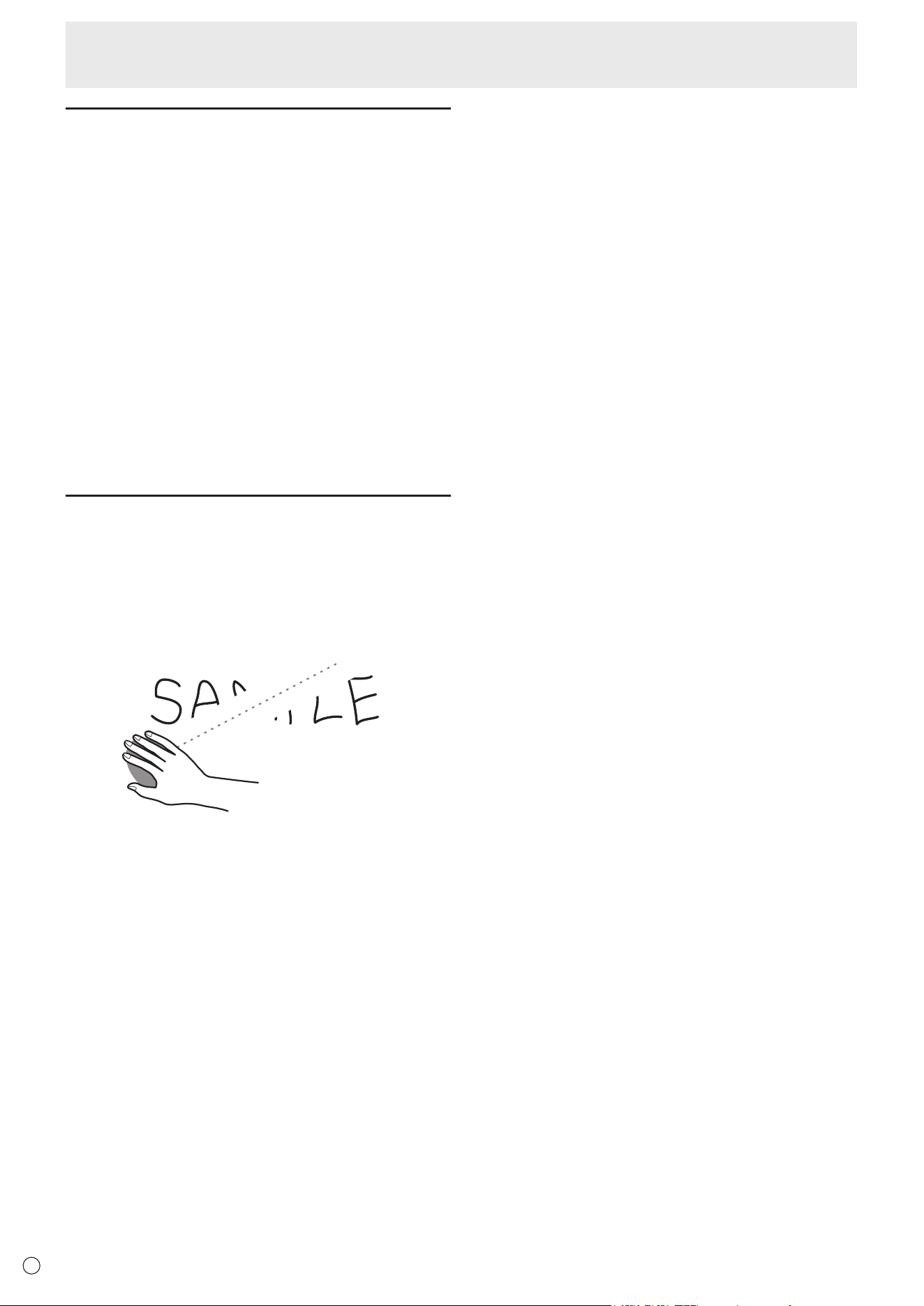
Eraser
InthePenSoftware,youcaneraseanareaofthescreenthat
youtouchwithyour5ngers.
1.SetERASERFUNCTIONtoON.(Seepage29.)
2.ChangetoFinger/penmode.(Seepage21.)
3.Youcantouchthescreenwith5ngers,andwhenthecursor
changestotheeraser,moveyourngers.
AlsoreadthePenSoftwaremanual.
25
E
Menu Items
Displaying the menu screen
Video and audio adjustment and settings of various functions
are enabled. This section describes how to use the menu
items. See pages 26 to 29 for details of each menu items.
Caution
• Do not turn the main power switch off while the menu items
are being displayed. Doing so may initialize the settings.
n
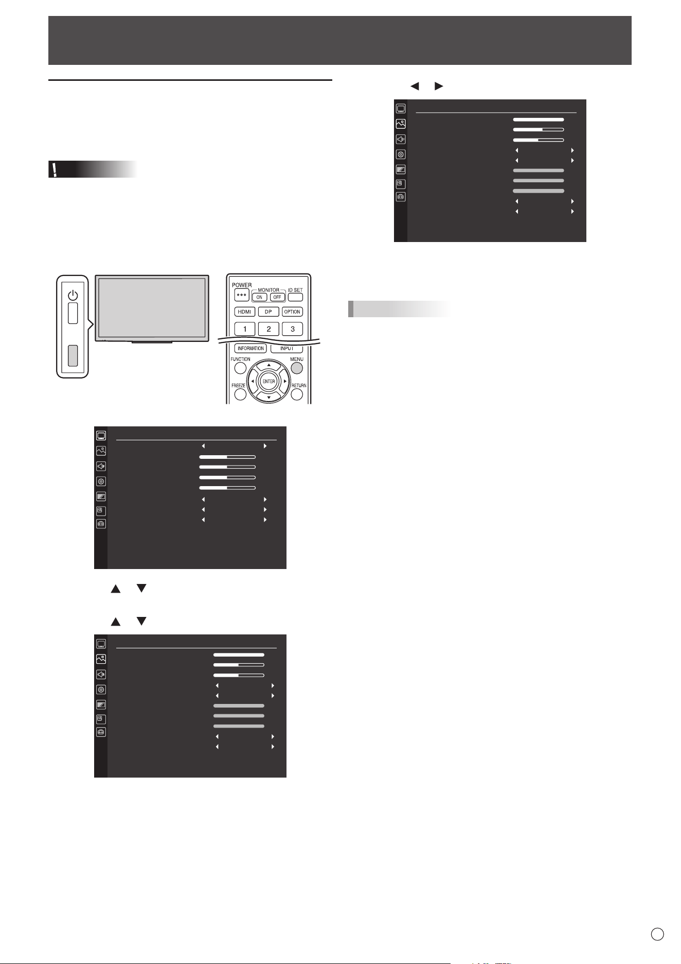
Example of operation
(Adjusting CONTRAST in the PICTURE menu)
1. Press the TOUCH MENU or MENU button.
TOUCH
MENU
The menu screen appears.
SCREEN
AUTO
CLOCK
PHASE
H-POS
V-POS
BACKLIGHT OFF
SIZE
RESET
50
50
50
50
OFF
WIDE
OFF
OFF
2. Press the or button
to select PICTURE, and press
the ENTER button.
3. Press the
or button
to select CONTRAST.
PICTURE
BRIGHT
CONTRAST
SHARPNESS
COLOR MODE
WHITE BALANCE
COLOR ADJUSTMENT
GAMMA
RESET
31
50
50
100
100
100
STD (PC)
THRU
MODE1
OFF
RED
GREEN
BLUE
4. Press the or button to adjust the setting.
PICTURE
BRIGHT
CONTRAST
SHARPNESS
COLOR MODE
WHITE BALANCE
COLOR ADJUSTMENT
GAMMA
RESET
31
60
50
100
100
100
STD (PC)
THRU
MODE1
OFF
RED
GREEN
BLUE
5. Press the TOUCH MENU or MENU button.
The menu screen closes.
TIPS
• The menu will differ depending on the input mode.
26
E
Menu Items
Menu item details
The menu will differ depending on the input mode.
■ SCREEN ( )
AUTO (D-SUB)
The CLOCK, PHASE, H-POS, and V-POS are automatically adjusted.
CLOCK (D-SUB)
Adjusts frequency for sampling clock for applicable video.
Adjust when there is ickering in the form of vertical stripes.
When using the adjustment pattern (see page 30), make adjustments so that no vertical stripe noise appears in it.
PHASE (D-SUB)
Adjusts sampling clock phase for applicable video. Useful when small characters appear with low contrast and/or there are ickers
at corners. When using the adjustment pattern (see page 30), make adjustments so that no horizontal stripe noise appears in it.
* Adjustments to PHASE should be made only after CLOCK has been correctly set.
H-POS (D-SUB)
Adjust the horizontal position of the image.
V-POS (D-SUB)
Adjust the vertical position of the image.
BACKLIGHT OFF
When set to ON, the backlight turns off. Audio does not turn off.
SIZE
Selects screen size. (See page 20.)
RESET
Resets the values of the SCREEN menu items to the factory preset values.
Select ON and then press the ENTER button.
■ PICTURE ( )
BRIGHT
Adjusts the backlight brightness. Brightness can also be adjusted using a remote control unit. (See page 19.)
CONTRAST
Adjusts the difference between the bright and dark portions of the image.
SHARPNESS
Adjusts the sharpness of the image.
COLOR MODE
Changes the color mode on the screen. The color mode on the screen can also be changed using a remote control unit. (See
page 18.)
WHITE BALANCE
THRU .................Displays the input signal level as is.
USER.................Used for adjusting of each of red component, green component, blue component respectively using COLOR
ADJUSTMENT.
6500K/9300K ..... The setting values are shown for reference. The color temperature of the screen varies over time. This
function is not intended to keep the color temperature constant.
COLOR ADJUSTMENT
Adjust item when the WHITE BALANCE is set to USER. Press the ENTER button to adjust.
RED ..........Adjusts bright-toned red component.
GREEN ..... Adjusts bright-toned green component.
BLUE ........Adjusts bright-toned blue component.
GAMMA
Selects the gamma.
RGB INPUT RANGE (HDMI/DisplayPort/OPTION)
Sets the RGB input signal range.
When using HDMI, DisplayPort or OPTION set to AUTO, the RGB input signal is detected automatically. Use AUTO normally.
If the RGB input signal range cannot be set appropriately even when using AUTO, set according to the image. When the
setting is different, images will be displayed with washed out blacks and compressed gradients.
RESET
Resets the values of the PICTURE menu items to the factory preset values.
Select ON and then press ENTER button.
27
E
Menu Items
■ AUDIO (
)
VOLUME
Adjusts the volume. Volume can also be adjusted using a remote control unit. (See page 18.)
AUDIO OUTPUT
Sets the volume of sound output from the audio output terminal.
VARIABLE1 ........ You can adjust the volume from the speakers of this monitor and the audio output terminal simultaneously
by using VOLUME.
VARIABLE2 ........ You can adjust the volume from the audio output terminal by using VOLUME.
Sound will not be output from the speakers of this monitor.
MUTE WITH FREEZE
Set whether or not audio turns off during freeze.
AUDIO SELECT (HDMI/DisplayPort/OPTION)
Selects the terminal used to input audio signals in each input mode.
RESET
Resets the values of the AUDIO menu items to the factory preset values.
Select ON and then press the ENTER button.
n
SETUP (
)
LANGUAGE
Sets the display language for the menu screen.
RS-232C/LAN SELECT
Selects the method with which to control the monitor from the computer.
BAUD RATE
Selects the communication speed used for RS-232C communication.
LAN SETUP
Congures the settings to control the monitor from the computer via LAN. (See page 36.)
Crestron Connected
Select this when using a Crestron device. When this function is set to ON, the monitor can be controlled via network using
equipment and application software of Crestron Electronics, Inc.
This monitor supports application software RoomView from Crestron Electronics, Inc.
This is a function to connect a system developed by Crestron Electronics, Inc. which manages and controls multiple system
devices connected to the network.
For details of Crestron Connected, refer to the Crestron Electronics, Inc. website. (Provided only In English.)
http://www.crestron.com/
For the download of RoomView Express, refer to the Crestron Electronics, Inc. website. (Provided only In English.)
http://www.crestron.com/getroomview
USB PORT SELECTION
Specify the setting for the USB and touch panel connection when the input mode is changed to or from OPTION.
AUTO ..............The connection automatically changes when the input mode changes.
EXTERNAL .....The USB and touch panel connection are xed at the computer connected to this monitor’s USB port (for
touch panel).
The touch panel and USB device cannot be used with the expansion slot device.
OPTION ..........The USB and touch panel connection is xed at the expansion slot device.
The touch panel and USB device cannot be used with this monitor.
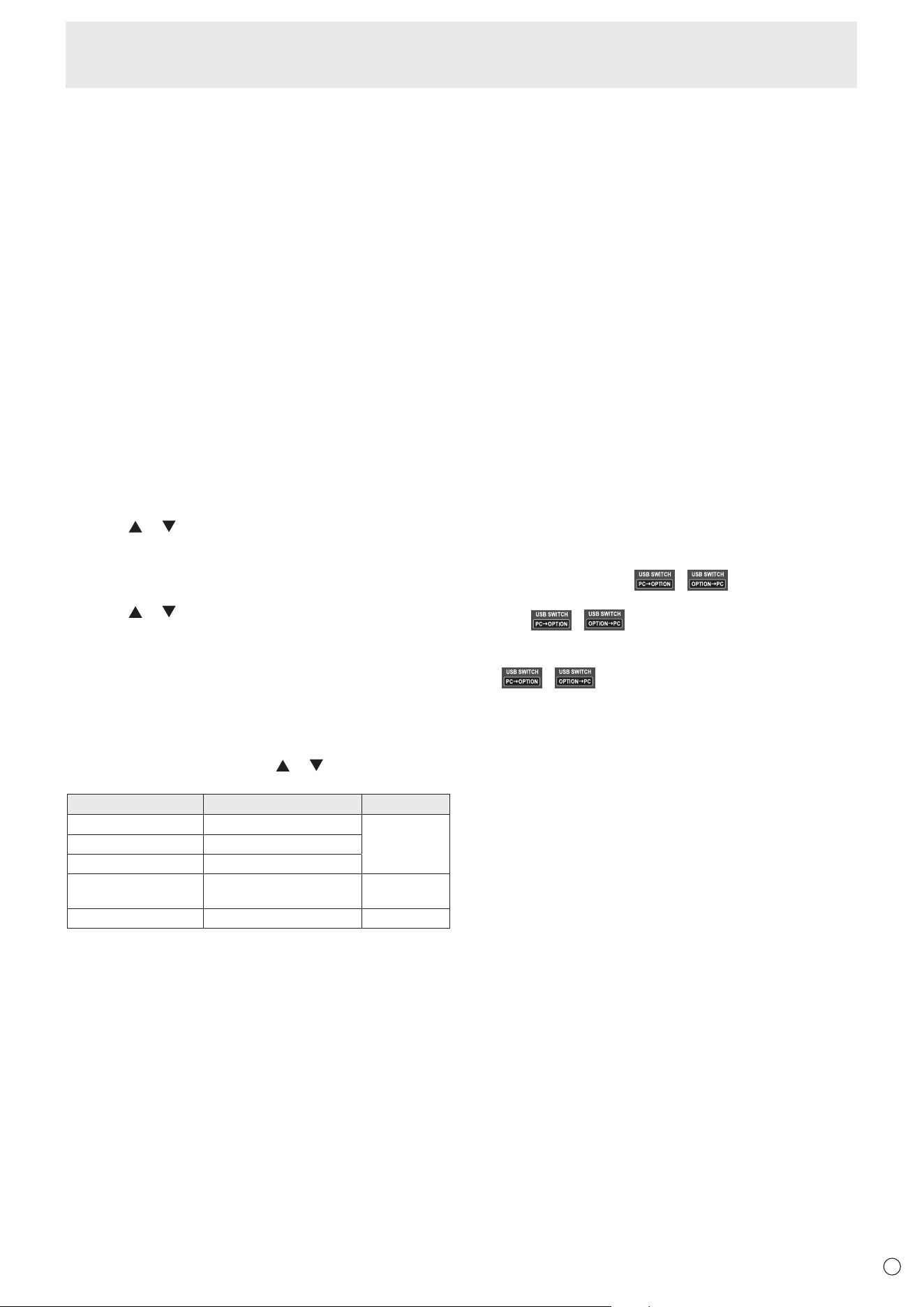
MANUAL .........When the input is changed,
( ) appears. (Approx. 5 seconds.)
Touch
( ) to change the connection.
If
( ) disappears, it will appear when the screen is touched.
INFORMATION
Displays monitor information. (See page 18.)
ALL RESET
Resets all the settings to the factory default settings. If the video is distorted after this is executed, turn off/on the main power.
28
E
Menu Items
n
MONITOR (
)
PORTRAIT/LANDSCAPE INSTALL
LANDSCAPE ..... Landscape orientation
PORTRAIT ........Portrait orientation
HORIZONTAL INSTALLATION
OFF ...................Portrait/landscape installation
UPWARD ........... The display screen faces up.
OSD H-POSITION
Adjusts the horizontal display position of menu screen.
OSD V-POSITION
Adjusts the vertical display position of menu screen.
POWER SAVE MODE
When OFF is selected, startup time from standby mode is reduced. Note, however that, more power will be consumed in
standby mode.
When ON is selected, current consumption is reduced while the monitor is in standby mode. Note, however, that the startup
time from standby mode becomes longer.
OFF IF NO OPERATION
Determines whether or not to set the monitor to go into standby mode when there is no operation from the remote control unit,
RS-232C commands, or LAN for over 4 hours.
n
PIP (
)
PIP MODES
Sets the display method.
OFF .................Displays one screen.
PIP ..................Displays a sub screen inside a main screen.
PbyP ................Displays a main screen and a sub screen in a line.
PIP SIZE
Sets the size of the sub screen in PIP mode.
PIP POS
Adjusts the position of the sub screen in PIP mode.
PIP SOURCE
Selects the input signal of the sub screen in PIP or PbyP mode.
SOUND CHANGE
Sets the sound which is output in PIP or PbyP mode.
RESET
Resets the values of the PIP menu items to the factory preset values.
Select ON and then press the ENTER button.
29
E
■ OTHERS ( )
POWER MANAGEMENT
POWER MANAGEMENT determines whether or not to switch modes from no signal to the input signal waiting mode.
NO SIGNAL AUTO INPUT SEL.
Specify whether to change inputs automatically. When ON is selected and no signal is present in the selected input mode, the
monitor automatically changes the selected mode to another mode where a video signal is present.
LOGO SCREEN
Sets whether or not to display the logo screen.
ERASER FUNCTION
Set whether or not the eraser function (see page 24) is used.
RESUME BY TOUCH
Set whether or not the screen is restored when touched in the input signal waiting mode.
OFF .................Turn off screen restoration.
ON ...................Turn on screen restoration. Note that this will increase power consumption in the input signal waiting mode.
TOUCH PANEL MODE (HDMI/D-SUB/DisplayPort/OPTION)
Setting this to ON improves touch panel tracking. Some input signals may also cause screen distortion. If the screen becomes
distorted, set to OFF.
OPTION
Set whether or not the expansion slot is used.
MONITOR LOCK
You can disable operations on the monitor and the remote control unit that use buttons.
OFF .................................. Enables operation.
REMOTE CONTROL ....... Prohibits remote control operation.
MONITOR BUTTONS ...... Prohibits monitor button operation.
BOTH ............................... Prohibits remote control and monitor button operation.
To release the operation lock, perform the steps below.
1. Press the SIZE button until “F” appears in the upper left corner of the screen.
2. While “F” is displayed, press the
, , , buttons in that order.
Menu Items
30
E
Menu Items
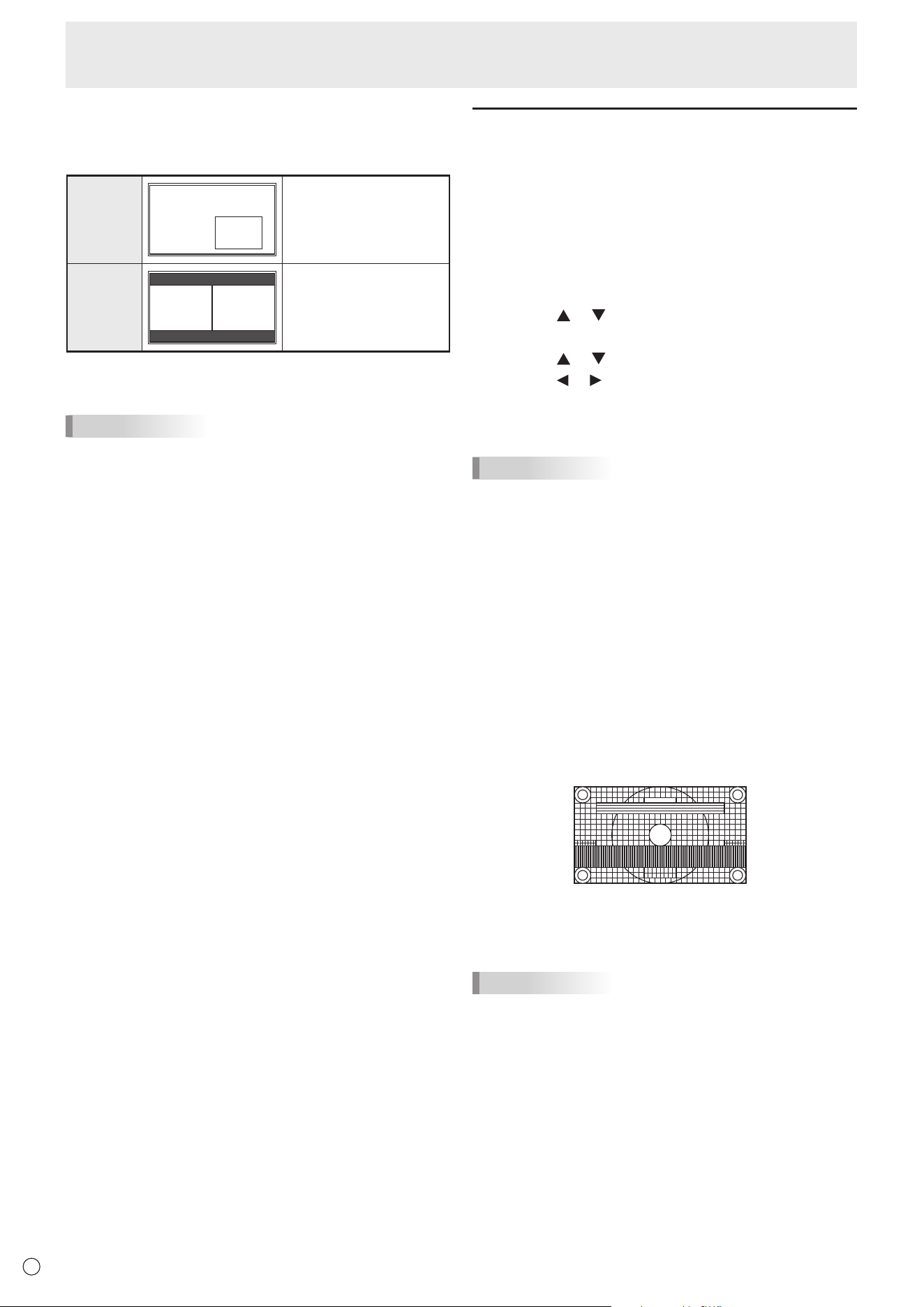
n
Dual screen display
You can display two screens simultaneously.
Set this function with PIP MODES in the PIP menu.
PIP
Main screen
Sub
screen
A sub screen is displayed
inside a main screen.
PbyP
Main
screen
Sub
screen
A main screen and a sub
screen are displayed in a
line.
* The currently selected input signal is displayed on the main
screen.
TIPS
• You might infringe on a copyright of the author which is
protected by copyright law when you display the images of
the computer screen and television/VCR simultaneously for
prot-making or to show the image to the public.
• The screen size for dual-screen display is the same as
the screen size for single-screen display. The Dot by Dot
screen is displayed in NORMAL size except when it is set
as the PIP main screen.
• When dual-screen display is selected, the NO SIGNAL
AUTO INPUT SEL. function is disabled.
• When an interlaced signal (1080i, 480i, video) is input to
the sub screen, horizontal lines may icker. If this happens,
display the image on the main screen.
• Touch operation cannot be used in the sub screen.
• When you set PbyP, touch action deviate.
Adjustments for computer screen
display
n
Automatic adjustment
When you use D-SUB to display a computer screen for the
rst time, or when you change the setting of the computer, use
the automatic screen adjustment.
1. Switch the input to D-SUB and display the adjustment
pattern. (See the description below.)
2. Press the TOUCH MENU or MENU button.
3. Press the
or button
to select SCREEN, and press
the ENTER button.
4. Press the
or button
to select AUTO.
5. Press the
or button
to select ON, and press the
ENTER button.
The automatic adjustment is complete in several seconds.
TIPS
• If the screen cannot be adjusted properly with one
automatic adjustment, repeat the automatic adjustment two
or three times. Try manual adjustment if necessary.
n
Screen display for adjustment
Before adjusting the image quality or picture, display an image
to brighten the entire screen. If you are using a Windows
computer, use the adjustment pattern on the supplied CD-
ROM.
Opening the adjustment pattern
The following example is performed in Windows 7.
1. Load the supplied CD-ROM into the computer’s CD-
ROM drive.
2. Open [CD Drive] in [Computer].
3. Double-click [Adj_uty.exe] in the [Monitor] folder.
The adjustment pattern will appear.
4. When adjustment is nished, press the [Esc] on the
computer’s keyboard to quit the adjustment program.
5. Eject the CD-ROM from the CD-ROM drive.
TIPS
• If the display mode on the computer you are using is 65000
colors, the color levels in the color pattern may appear
differently or grayscale may appear to be colored. (This
is due to the specications of the input signal and is not a
malfunction.)
31
E
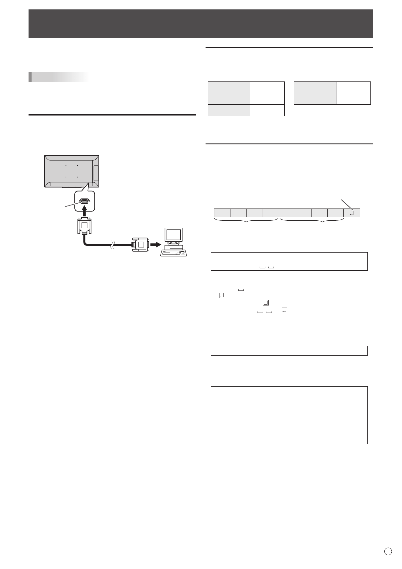
Controlling the Monitor with a computer (RS-232C)
You can control this monitor from a computer via RS-232C
(COM port) on the computer.
TIPS
• To control the monitor via RS-232C, set RS-232C/LAN
SELECT to RS-232C.
• You cannot use RS-232C and LAN control simultaneously.
Computer connection
Connect with RS-232 straight cable between the computer’s
COM port (RS-232C connector) and the RS-232C input
terminal on the monitor.
To COM port
Computer
RS-232C
input terminal
RS-232 straight cable
(commercially available)
Communication conditions
Set the RS-232C communication settings on the computer to
match the monitor’s communication settings as follows:
Baud rate *
Stop bit
1 bit
Data length 8 bits Flow control None
Parity bit None
* Set to the same baud rate as the BAUD RATE setting of
SETUP menu. (Initial setting: 38400 bps)
Communication procedure
n
Command format
When a command is sent from the computer to the monitor,
the monitor operates according to the received command and
sends a response message to the computer.
C1 C2 C3 C4 P1 P2 P3 P4
Return code
Command field
(4 prescribed
alphanumerical characters
)
Parameter field
(4 character string comprised of:
0-9, +, -, space, ?)
Example: VOLM0030
VOLM
30
* Be sure to input 4 characters for the parameter. Pad with
spaces (“
”) if necessary.
(“
” is a return code (0D
H
, 0A
H
or 0D
H
))
Wrong : VOLM30
Right : VOLM 30
When the parameter part is 5 or more characters, specify
parameters using a specied number of characters without
using spaces.
Example: TCPP01025
If a command has “R” listed for “DIRECTION” in the
“RS-232C command table” on page 33, the current value can
be returned by using “?” as the parameter.
Example:
VOLM ? ? ? ? ←
From computer to monitor
(How much is current volume
setting?).
30 ←
From monitor to computer
(Current volume setting: 30).
32
E
Controlling the Monitor with a computer (RS-232C)
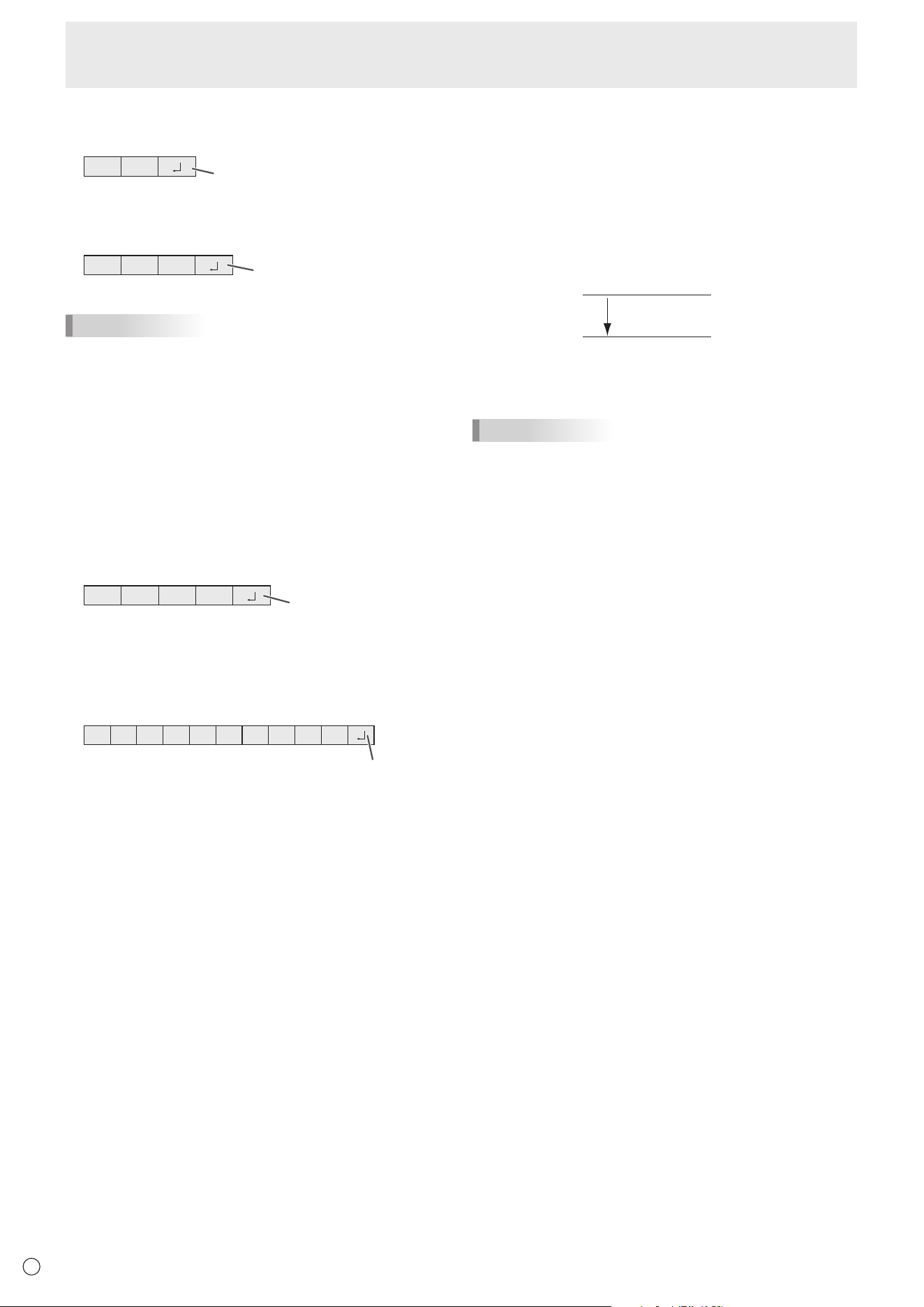
n
Response code format
When a command has been executed correctly
O K
Return code
(0DH, 0AH)
A response is returned after a command is executed.
When a command has not been executed
R R E
Return code
(0DH, 0AH)
TIPS
• “ERR” is returned when there is no relevant command or
when the command cannot be used in the current state of
the monitor.
• If communication has not been established for reasons
such as a bad connection between the computer and
monitor, nothing is returned (not even ERR).
• “ERR” may be returned when a command cannot be
received correctly due to interference from the surrounding
environment.
Please ensure that the system or software retries the
command if this occurs.
If execution of the command is taking some time
I W T A
Return code
(0DH, 0AH)
There is command “WAIT” is returned as a returned value. In
this case, a value will be returned if you wait a while. Do not
send any command during this period.
When RS-232C/LAN SELECT is set to LAN
U N S E L E C T E D
Return code
(0DH, 0AH)
n
Communication interval
• After OK or ERR is returned, you must send the following
commands.
To set a timeout for the command response, specify 10
seconds or longer.
• Provide an interval of 100 ms or more between the
command response and the transmission of the next
command.
VOLM0020
OK
INPS0002
WAIT
OK
Interval of 100 ms or more
TIPS
• When executing ALL RESET, set the timeout period to 30
seconds or longer.
33
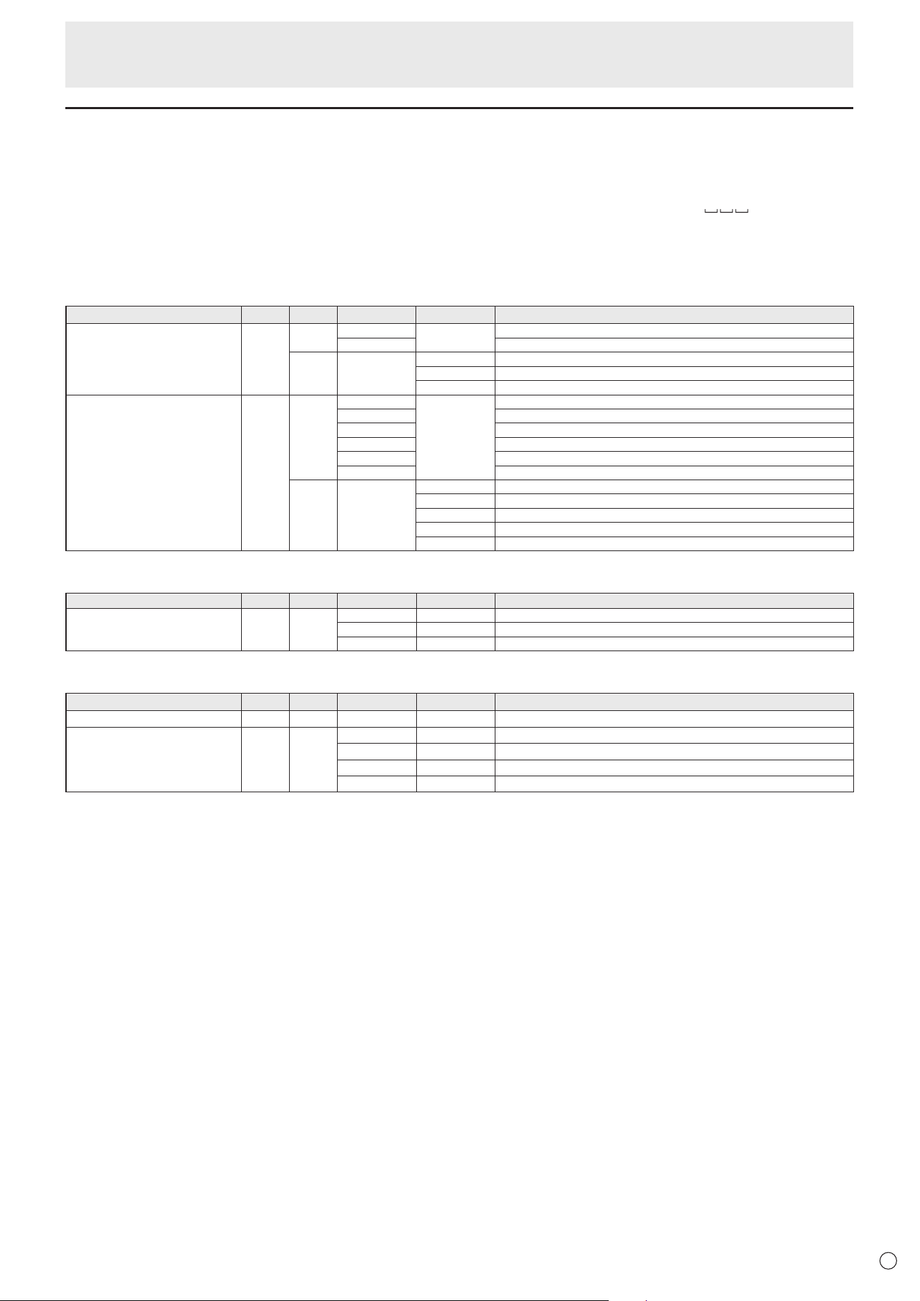
E
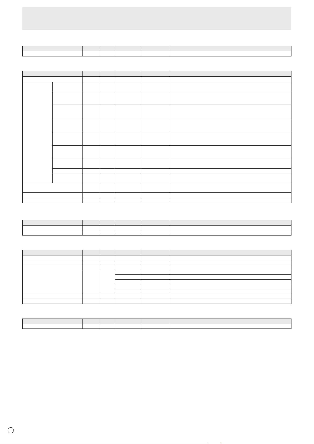
RS-232C command table
How to read the command table
Command: Command eld (See page 31.)
Direction: W When the “Parameter” is set in the parameter eld (see page 31), the command functions as described
under “Control/Response Contents”.
R The returned value indicated under “Reply” can be obtained by setting “????” or “
?” in the
parameter eld (see page 31).
Parameter: Parameter eld (See page 31.)
Reply: Response (Returned value)
Controlling the Monitor with a computer (RS-232C)
Power control/Input mode selection
Function
Command Direction
Parameter Reply Control/Response contents
POWER CONTROL POWR W 0
Switches to standby mode.
1 Enters the power ON state.
R 0 Standby mode
1 Normal mode
2 Input signal waiting mode
INPUT MODE SELECTION INPS W 0 Toggle change for input mode.
2 D-SUB
10 HDMI1
13 HDMI2
14 DisplayPort
21 OPTION
R 2 D-SUB
10 HDMI1
13 HDMI2
14 DisplayPort
21 OPTION
SCREEN menu
Function
Command Direction
Parameter Reply Control/Response contents
SIZE WIDE WR 1 1 WIDE
3 3 Dot by dot
6 6 NORMAL
PICTURE menu
Function
Command Direction
Parameter Reply Control/Response contents
BRIGHT VLMP WR 0-31 0-31
COLOR MODE BMOD WR 0 0 STD (PC)
4 4 HIGH ILLUMINANCE
9 9 AV
10 10 USER
34
E
Controlling the Monitor with a computer (RS-232C)
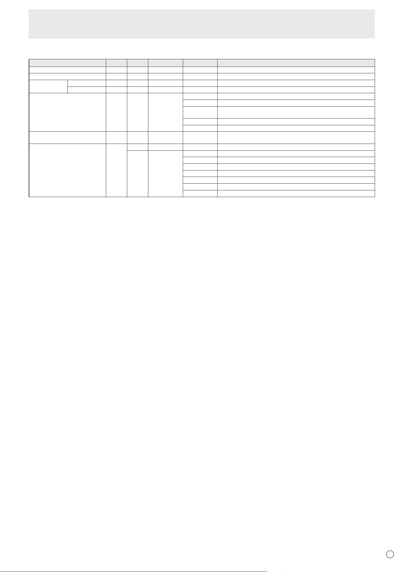
AUDIO menu
Function
Command Direction
Parameter Reply Control/Response contents
VOLUME VOLM
WR 0-31 0-31
SETUP menu
Function
Command Direction
Parameter Reply Control/Response contents
RS-232C/LAN SELECT CTLS WR
0-1 0-1
0: RS-232C 1: LAN
LAN SETUP DHCP CLIENT DHCP WR 0-1 0-1 0: OFF, 1: ON
* Apply the settings to this monitor by NTUP.
IP ADDRESS IPAD WR
XXXXXXXXXXXX XXXXXXXXXXXX X: Only number is ok. If the number is less than 3 digits, to three digits to ll zero.
Example: 192168150001
* Apply the settings to this monitor by NTUP.
SUBNET MASK SBMK WR
XXXXXXXXXXXX XXXXXXXXXXXX X: Only number is ok. If the number is less than 3 digits, to three digits to ll zero.
Example: 255255255000
* Apply the settings to this monitor by NTUP.
DEFAULT
GATEWAY
DFGW WR
XXXXXXXXXXXX XXXXXXXXXXXX X: Only number is ok. If the number is less than 3 digits, to three digits to ll zero.
Example: 000000000000
* Apply the settings to this monitor by NTUP.
User name USER WR XXXXXXXX XXXXXXXX Set the username for connection to this monitor by LAN.
X: 8 characters or less; half-width alphanumeric characters, “-”, and “_”.
(The eld can be left blank, but spaces cannot be entered.)
Password PASS WR XXXXXXXX XXXXXXXX Set the password for connection to this monitor by LAN.
X: 8 characters or less; half-width alphanumeric characters, “-”, and “_”.
(The eld can be left blank, but spaces cannot be entered.)
Monitor name MNTR WR
XXXXXXXX
XXXXXXXX
XXXXXXXX
XXXXXXXX
X: 16 characters or less; half-width alphanumeric characters, “-”, and “_”.
(The eld can be left blank, but spaces cannot be entered.)
Auto logout time LOTM WR
00000-65535 00000-65535
Set the time that display terminate a network connection automatically by minutes.
Data port TCPP WR
01025-65535 01025-65535
Set the TCP port number for data communication.
* Apply the settings to this monitor by NTUP.
Reecting LAN setting NTUP W
1
1 Applies the DHCP CLIENT, IP ADDRESS, SUBNET MASK, DEFAULT GATEWAY,
and Data port settings to this monitor.
Crestron Connected CRCN WR 0-1 0-1 0: OFF, 1: ON
ALL RESET RSET W
1
1: ALL RESET
MONITOR menu
Function
Command Direction
Parameter Reply Control/Response contents
PORTRAIT/LANDSCAPE INSTALL STDR WR 0-1 0-1 0: LANDSCAPE, 1: PORTRAIT
HORIZONTAL INSTALLATION
MLAY WR 0-1 0-1 0: OFF, 1: UPWARD
PIP menu
Function
Command Direction
Parameter Reply Control/Response contents
PIP MODES MWIN WR 0-2 0-2 0: OFF, 1: PIP, 2: PbyP
PIP SIZE MPSZ WR 0-2 0-2 0: SMALL, 1: MEDIUM, 2: LARGE
PIP POS MWPS WR 0-3 0-3 0: UPPER RIGHT, 1: UPPER LEFT, 2: LOWER RIGHT, 3: LOWER LEFT
PIP SOURCE MWIP WR 2 2 D-SUB
10 10 HDMI1
13 13 HDMI2
14 14 DisplayPort
21 21 OPTION
SOUND CHANGE MWAD WR 1-2 1-2 1: MAIN, 2: SUB
RESET RPIP W 1
OTHERS menu
Function
Command Direction
Parameter Reply Control/Response contents
MONITOR LOCK ALTG WR 0-3 0-3 0: REMOTE CONTROL, 1: MONITOR BUTTONS, 2: BOTH, 3: OFF
35
E
Others
Function
Command Direction
Parameter Reply Control/Response contents
RESOLUTION CHECK PXCK R - Returns current resolution in the form of hhh, vvv.
MUTE MUTE WR 0-1 0-1 0: OFF, 1: ON
INFORMATION MODEL INF1 R Value
SERIAL NO SRNO R Value
TEMPERATURE SENSOR DSTA R 0 Internal temperature normal
1 Internal temperature abnormal has occurred and the monitor is in standby mode
2 Internal temperature abnormal occurred (To delete the information of temperature
abnormal, turn off the main power.)
3 Internal temperature abnormal has occurred and backlight brightness is dimmed
4 Temperature sensor abnormal
TEMPERATURE ACQUISITION ERRT R Value Returns the temperature at the temperature sensors.
Indicates a temperature sensor abnormality when “126” is returned.
CAUSE OF LAST STANDBY MODE STCA W 0 Initialization
R 0 No detectable error has occurred
1 Standby mode by POWER button
2 Main power off by the main power switch
3 Standby mode by RS-232C or LAN
4 Input signal waiting mode by No Signal
6 Standby mode by abnormal temperature
20 Standby mode by OFF IF NO OPERATION setting
Controlling the Monitor with a computer (RS-232C)
36
E
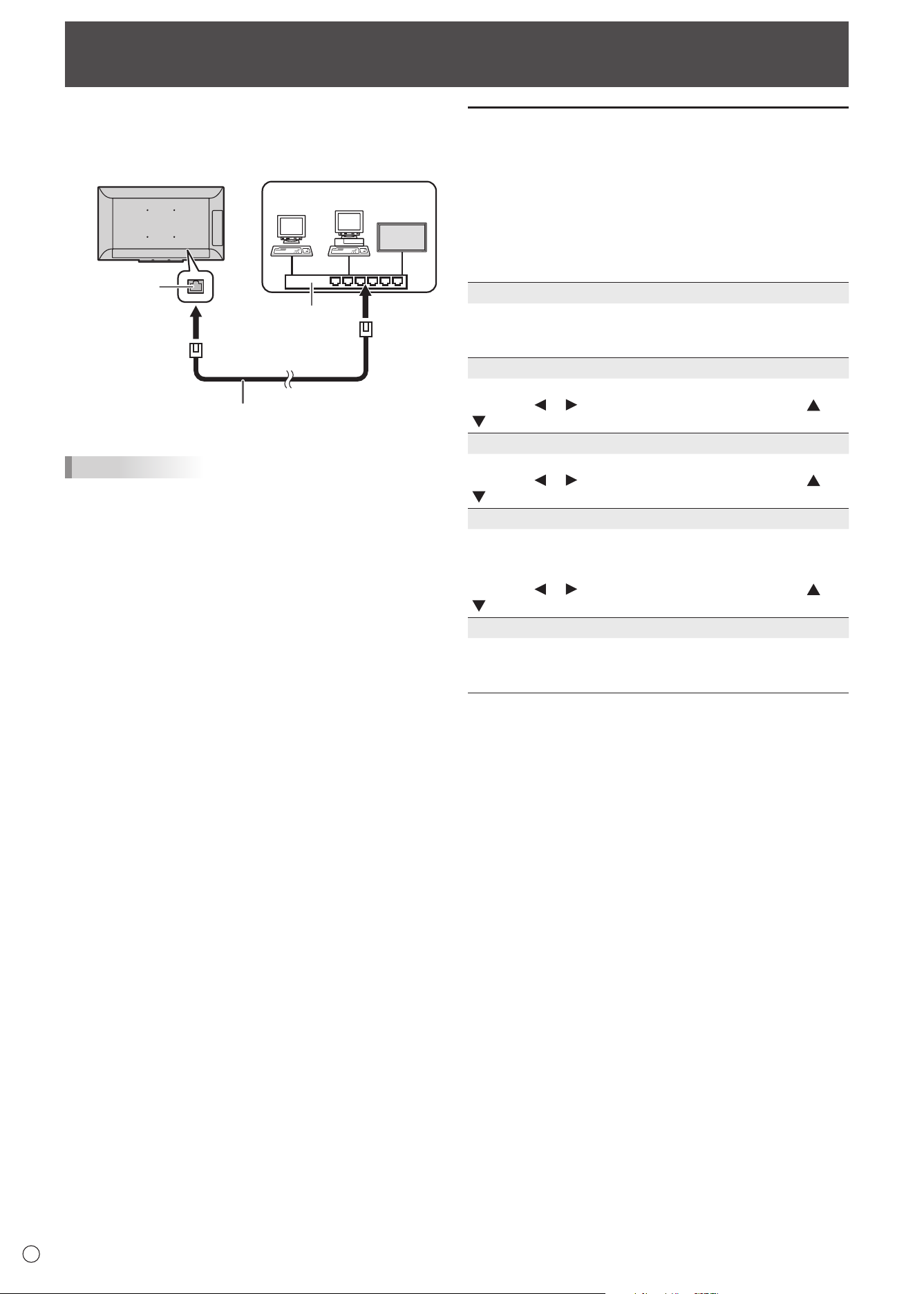
Your monitor can be connected to a LAN allowing you to
control it from a computer on the LAN.
The connection requires a commercially available LAN cable
(UTP cable, Category 5, straight through).
LAN terminal
LAN cable (commercially available, straight)
Network (LAN)
Hub
TIPS
• You must assign an IP address to the monitor by following
the procedures in “Settings to connect to a LAN”. (See the
description on the right.)
• When POWER SAVE MODE is set to ON, control is not
possible in standby mode.
• To control the monitor via LAN, set RS-232C/LAN SELECT
to LAN. (See page 27.)
• You cannot use RS-232C and LAN control simultaneously.
Controlling the Monitor with a computer (LAN)
Settings to connect to a LAN
Set the monitor’s IP address and subnet mask to match the
settings of your LAN.
The settings depend on the conguration of your LAN. Ask
your LAN administrator for details.
Set RS-232C/LAN SELECT on the SETUP menu to LAN, and
then set the LAN SETUP options. (See page 27.)
After setting each item, select SET in SET/RESET and press the
ENTER button.
DHCP CLIENT
If your LAN has a DHCP server and you wish to obtain an
address automatically, change this setting to ON.
To set the address manually, set this to OFF.
IP ADDRESS
If the DHCP CLIENT is set to OFF, specify an IP address.
Press the
or button to select items, and press the or
button to change the values.
SUBNET MASK
If the DHCP CLIENT is set to OFF, specify the subnet mask.
Press the
or button to select items, and press the or
button to change the values.
DEFAULT GATEWAY
If the DHCP CLIENT is set to OFF, specify the default
gateway.
If you are not using a default gateway, specify “0.0.0.0”.
Press the
or button to select items, and press the or
button to change the values.
SET/RESET
SET .................... Applies the LAN settings to the monitor.
RESET ............... Resets the LAN settings to the factory
preset values.
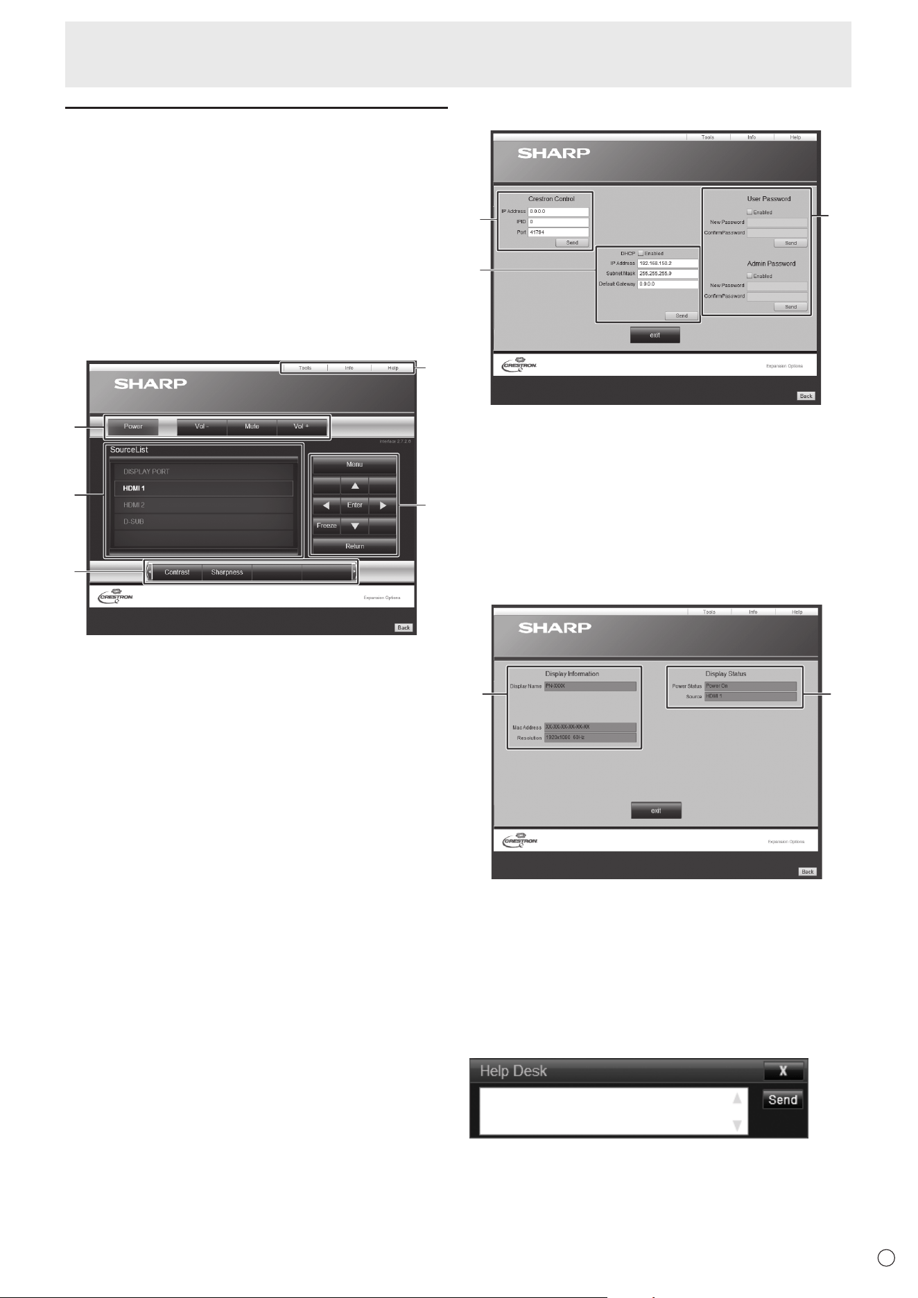
37
E
Controlling the Monitor with a computer (LAN)
Crestron Connected
You use the web browser on a computer on the LAN to control
the monitor.
Access the monitor using the web browser.
1. Launch the web browser on the computer.
2. In the “Address” box, type “http://” followed by your
monitor’s IP address followed by “/”, then press the
Enter key.
You can conrm the IP address with the INFORMATION
function.
Display the Crestron Connected control menu.
Control Menu
1
2
3
4
5
1. Operate below functions.
• Power.........Turn the power ON/OFF.
• Mute ........... Turns off the volume temporarily.
• Vol-/Vol+ ....Adjust the volume of the sound.
2. Change the input mode.
3. Operate below functions.
• Contrast ........ Adjusts the contrast.
• Sharpness..... Adjusts the sharpness.
4. Operates the menu screen for the monitor.
5. Switches the pages to tools, information and help tab.
Tools
1
2
3
1. Setting for Crestron Control.
2. Setting for monitor network.
• DHCP
• IP Address
• Subnet Mask
• Default Gateway
3. Security Setting.
Sets the password for the user and administrators rights on
Control Menu.
Info
1
2
1. Display below information.
• Display Name
• Mac Address
• Resolution
2. Display below status.
• Power Status
• Input
Help
Sends or receives messages to the administrators who uses
“Crestron Connected”.
38
E
Controlling the Monitor with a computer (LAN)
Command-based control
You can control the monitor using RS-232C commands
(see page 31) via terminal software and other appropriate
applications.
Read the manual for the terminal software for detailed
instructions.
(1) Connect the computer to the monitor.
1. Specify the IP address and data port number (10008)
and connect the computer to the monitor.
When connection has been established successfully,
[
Login:] is returned as response.
2. Send the user name.
• Send [User name] + [
].
• If the user name is not set, send [
].
• When the transmission is successful, [
Password:]
is returned as response.
3. Send the password.
• Send [Password] + [
].
• If the password is not set, send [
].
• When the transmission is successful, [OK
] is
returned as response.
(2) Send commands to control the monitor.
• The commands used are the same as those for RS-
232C. Refer to the communication procedure (see
page 31) for operation.
• Usable commands are provided in the RS-232C
command table (see page 33).
(3) Disconnect the connection with the monitor and
quit the function.
1. Send [BYE ].
When the transmission is successful, [goodbye] is
returned and the connection is disconnected.
TIPS
• Connection is automatically disconnected when the
time specied in AUTO LOGOUT TIME elapses over a
no-communication period.

39
E
Troubleshooting
If you are experiencing any problem with your display, before
calling for service, please review the following troubleshooting
tips.
There is no picture or sound.
• ThepowerLEDisoff
- Is power supplied to this monitor?
- Is the power cord disconnected? (See page 13.)
- Is the main power switch off? (See page 17.)
• ThepowerLEDlightsorange
-Thismonitorisinstandbymode.Turnonthepower. (See
page 17.)
• ThepowerLEDashesgreen
-Thereisnoinputsignal.
- Is an input mode selected that is appropriate for the input
terminal to which the cable is connected? (See page 19.)
- If any external equipment is connected, make sure the
equipment is operating (playing back).
Remote control does not work.
• Arethebatteriesinsertedwithpolarity(+,-)aligned?(See
page 15.)
• Arethebatteriesexhausted?
• Pointtheremotecontrolunittowardthemonitor’sremote
control sensor. (See page 15.)
• IstheremotecontroloperationinMONITORLOCKof
OTHERSmenuenabled?(Seepage29.)
Sound from left and right speakers is reversed.
Sound is heard from only one side.
• Areaudiocablesconnectedproperly?(Seepage12.)
There is a picture but no sound.
• Isthesoundmuted?(Seepage18.)
• Makesurethevolumeisnotsettominimum.(Seepage
18.)
• Areaudiocablesconnectedproperly?
• WhenAUDIOOUTPUTissettoVARIABLE2intheAUDIO
menu,thespeakerismuted.Checkthesetting.(Seepage
27.)
Unstable video.
• Thesignalmaybeincompatible.(Seepages43and44.)
• SetTOUCHPANELMODEontheOTHERSmenutoOFF.
The video from the HDMI input terminal does not appear
properly.
• IstheHDMIcableHDMIstandardcompliant?Themonitor
will not work with cables that are not standard compliant.
• Istheinputsignalcompatiblewiththismonitor?(Seepages
43and44.)
The video from DisplayPort input terminal does not
appear correctly.
• Istheinputsignalcompatiblewiththismonitor?(Seepage
43.)
• IstheDisplayPortcableDisplayPortstandardcompliant?
Themonitorwillnotworkwithcablesthatarenotstandard
compliant.
The video from D-sub input terminal does not appear
correctly.
•
Istheinputsignalcompatiblewiththismonitor?(Seepage43.)
Video color is strange.
• IsthePICTUREmenusettingcorrect?Youcanexecute
RESETtoreturntothefactorydefaultsettings.
(See page
26.)
Control buttons do not work.
There is no picture.
• Loadnoisesfromoutsidemaybeinterferingwithnormal
operation.Turnoffthemainpowerandturnitonafter
waiting at least 5 seconds, and then check the operation.
(See page 17.)
• Turnonthemonitorrstbeforeturningonthecomputeror
playback device.
The input mode changes automatically.
• WhentheNOSIGNALAUTOINPUTSEL.isONandno
signal is present in a selected input mode, the monitor
automatically changes the selected mode to a mode where
a video signal is present.
Theinputmodemaychangeinthefollowingcases:
-Whenacomputerisinstandbymode.
-Whenvideoplayisstoppedwithaplaybackdevice.
The touch panel does not respond.
• IstheUSBcableconnectedproperly?
• Isthemonitorinpen-onlymode?Touchactionisdisabled
inpen-onlymode.(Seepage19and21.)
• Isthemonitorinnger-onlymode?Youcannottouchthe
screenwiththetouchpenwheninnger-onlymode.(See
page19and21.)
• Ifyourngeristoodry,thescreenmaynotrespond.
• Donottouchthescreenwhenthemonitorpoweristurned
on,itwillleadtoamalfunction.Whenthisoccurs,turnthe
monitor power off and then on.
• UseonlythesuppliedUSBcable.Ifthecommercially
availableUSBcableisused,thetouchpanelmaynot
operate correctly.
If you want to position the monitor further away than the
USBcablewillallow,extendthecableusingaUSBcable
with a repeater.
• WhenUSBPORTSELECTIONisOPTION,thetouchpanel
cannot be used with the computer that is connected to this
monitor.
When “AUTO DIMMING” is displayed.
• Whentheinternaltemperatureofthemonitorrises
excessively, the brightness of the backlight automatically
decreases in order to prevent a further temperature rise. If
you attempt to adjust the brightness while the monitor is in
thisstate,“AUTODIMMING”isdisplayedandyoucannot
change the brightness.
• Removethecauseoftheexcessivetemperaturerise.
The monitor makes a cracking sound.
• Youmayoccasionallyhearacrackingsoundfromthe
monitor.Thishappenswhenthecabinetslightlyexpands
andcontractsaccordingtochangeintemperature.This
doesnotaffectthemonitor’sperformance.

40
E
The Power LED is ashing in red and green alternately.
When “AUTO DIMMING” is displayed in the corner of the
screen.
• When the internal temperature of the monitor rises
excessively, the brightness of the backlight decreases
automatically in order to prevent high-temperature-
related problems. When this occurs, “AUTO DIMMING” is
displayed on the screen and the Power LED ashes red
and green alternately.
• If the internal temperature rises further, the monitor
automatically enters standby mode. (The Power LED
continues ashing red and green alternately.)
• Remove the cause of the excessive temperature rise.
- If the monitor enters standby mode due to a rise in
temperature, to return to normal display, turn the power
switch off and then back on again. The monitor, however,
will enter standby mode again if the cause of the
temperature rise is not eliminated. (See page 7.)
- Check whether the monitor is placed at a location where
a quick rise in temperature is likely. Internal temperature
rises quickly if the vents on the monitor are blocked.
- Internal temperature rises quickly if dust accumulates
inside the monitor or around the vents. Remove dust if
possible. Ask SHARP dealer about removing internal dust.
The inner side of the glass is cloudy.
• When the humidity is high, the inner side of the glass
may cloud after the power is turned on. The cloudiness is
caused by the difference between the ambient temperature
and the temperature of the air inside the glass, and is
not a malfunction. You can continue to use the monitor to
disappear the cloudiness.
Troubleshooting
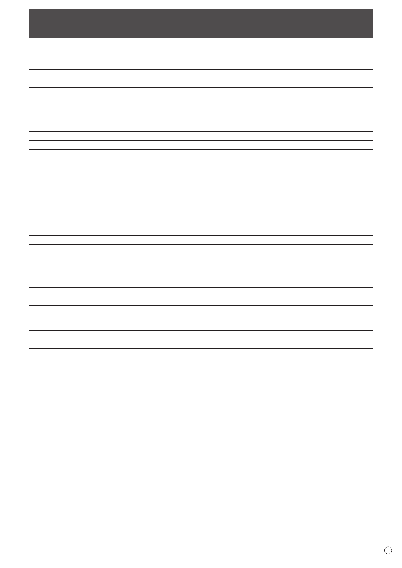
41
E
Specications
n
Product Specications
Model
PN-L501C
LCD component
50" Class [49-1/2 inch (125.7cm) diagonal] TFT LCD
Max. resolution (pixels)
1920 x 1080
Max. colors
Approx. 16.77 million colors
Pixel pitch
0.571 mm (H) × 0.571 mm (V)
Max. brightness (typical)
*
1
340 cd/m
2
(LCD panel : 400 cd/m
2
)
Contrast ratio (typical) 5000 : 1
Viewing angle
178° right/left/up/down (contrast ratio ≥ 10)
Screen active area inch (mm)
43-1/8 (W) x 24-1/4 (H) (1095.84 x 616.41)
Computer input signal
Analog RGB (0.7 Vp-p) [75
Ω
],
HDMI
, DisplayPort
Sync signal
Horizontal/vertical separate (TTL: positive/negative)
Plug and play
VESA DDC2B
Power management
VESA DPMS
Input terminals
Video HDMI x 2
DisplayPort x 1
Mini D-sub 15 pin, 3 rows x 1
Audio
3.5 mm mini stereo jack x 1
Serial (RS-232C) D-sub 9 pin x 1
Output terminals Audio
3.5 mm mini stereo jack x 1
LAN terminal 10 BASE-T/100 BASE-TX
USB port Type A (USB 2.0 compliant) x 2
Speaker output 10 W + 10 W
Touch Panel
Detection method Capacitive type
Computer connector USB (2.0 compliant) (type B) x 1
Expansion slot
12 V, 2.5 A
(power supplied when expanding the functions with an optional part)
Power requirement
AC 100 V - 240 V, 1.2 A, 50/60 Hz
Operating temperature
*
2
*
3
41°F to 95°F (5°C to 35°C)
Operating humidity
*
3
20% to 80% (no condensation)
Power consumption
(input signal waiting mode
*
4
*
5
/ standby mode
*
6
)
105 W (2 W/2 W)
Dimensions (excluding protrusions) inch (mm)
Approx. 45-5/16 (W) x 2-11/16 (D) x 27 (H) (1151 x 68.5 x 686)
Weight lbs. (kg)
Approx. 61.7 (28)
*1 Brightness will depend on input mode and other picture settings. Brightness level will decrease over time. Due to the nature of the
equipment, it is not possible to precisely maintain a constant level of brightness.
*2 When using the monitor laying at on a surface (when the monitor is tilted more than 20 degrees upward from the perpendicular in relation
to a level surface), use the monitor at a temperature between 41°F (5°C) and 86°F (30°C).
Temperature condition may change when using the monitor together with the optional equipments recommended by SHARP. In such
cases, please check the temperature condition specied by the optional equipments.
*3 In addition, check the requirements of the computer and other devices to be connected, and make sure that all requirements are satised.
*4 When the optional part is not installed.
*5 When NO SIGNAL AUTO INPUT SEL. is set to OFF.
*6 When POWER SAVE MODE is set to OFF.
When POWER SAVE MODE is set to ON: 0.5 W
As a part of our policy of continuous improvement, SHARP reserves the right to make design and specication changes for product improvement
without prior notice. The performance specication gures indicated are nominal values of production units. There may be some deviations from
these values in individual units.
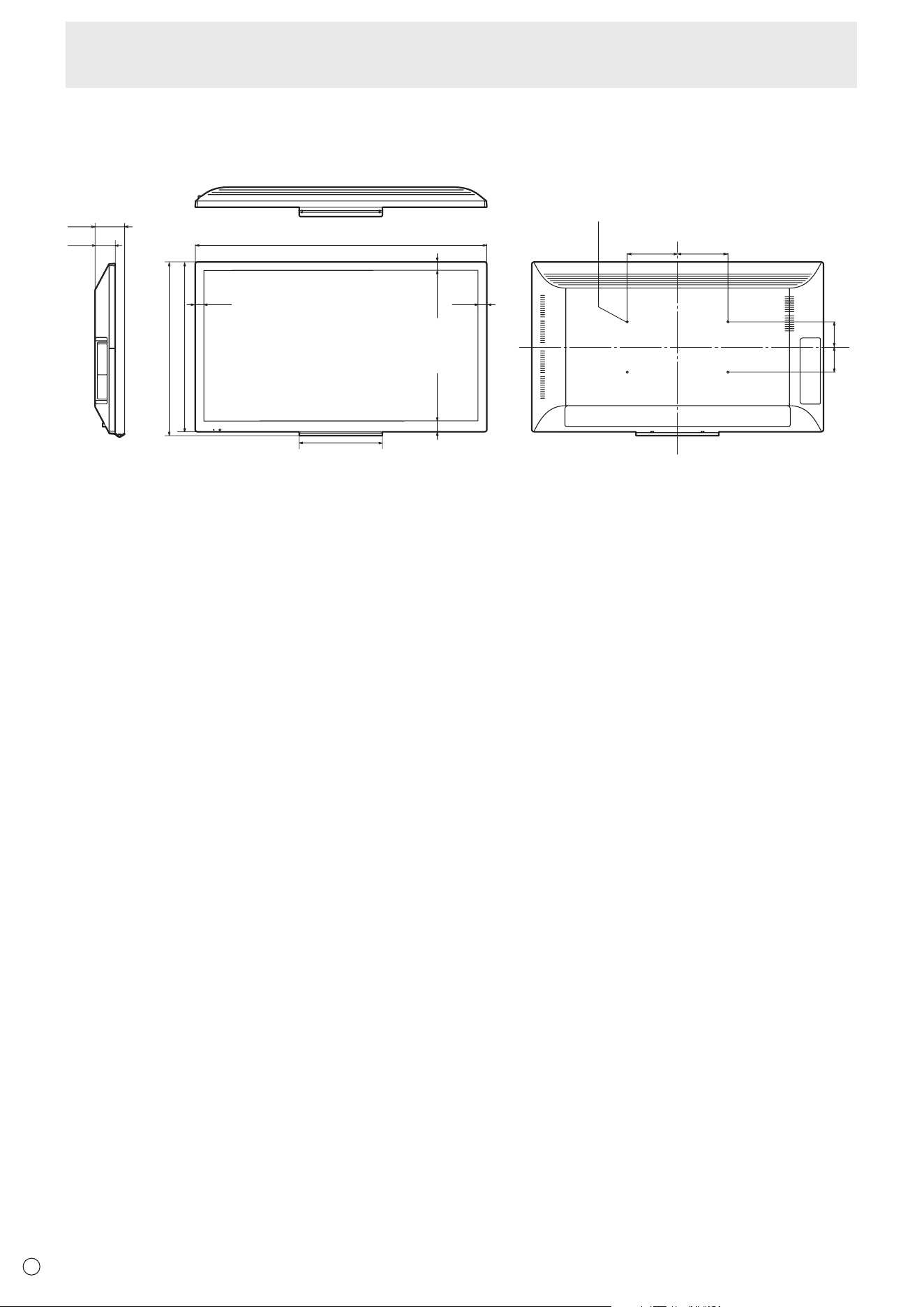
42
E
Specications
n
Dimensional Drawings
Note that the values shown are approximate values.
3-15/16
[100]
3-15/16
[100]
7-7/8
[200]
7-7/8
[200]
45-5/16 [1151]
12-15/16 [329]
2-
11/16
[68.5]
3-7/8
[98]
Unit: inch [mm]
VESA holes *
27 [686]
27-9/16 [700]
1-5/16 [33]
1-5/16 [33]
1 [26] 1 [26]
* When mounting the monitor, be sure to use a wall-mount bracket that complies with the VESA-compatible mounting method.
SHARP recommends using M6 screws and tighten the screws.
Note that screw hole depth of the monitor is 1/2 inch (12 mm). Loose mounting may cause the product to fall, resulting in
serious personal injuries as well as damage to the product. The screw and hole should come together with over 3/8 inch
(10 mm) length of thread. Use a bracket which has been approved for UL1678 standard, and which can endure at least 4 times
or more the weight of the monitor.
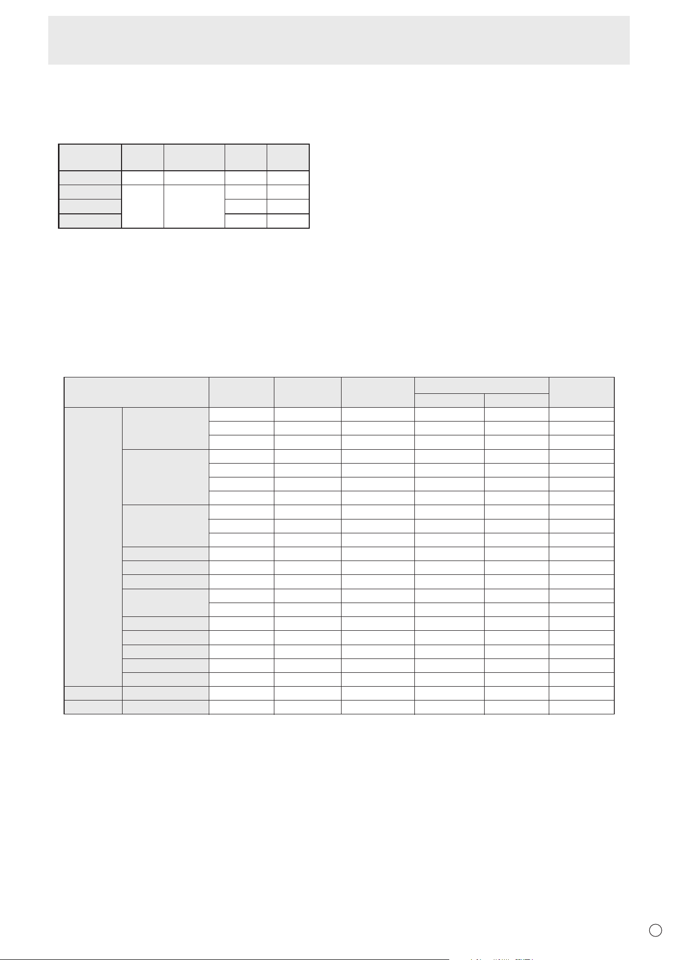
43
E
n
Power management
This monitor conforms to VESA DPMS. Both your video card and computer must support the same standard in order for the
monitor’s power management function to work.
DPMS: Display Power Management Signaling
DPMS Screen
Power
consumption
Hsync Vsync
ON STATE Display 105 W Yes Yes
STANDBY
No
display
2 W*
No Yes
SUSPEND Yes No
OFF STATE No No
* When NO SIGNAL AUTO INPUT SEL. is set to OFF.
n
DDC (plug and play)
The monitor supports the VESA DDC (Display Data Channel) standard.
DDC is a signal standard for plug and play between monitors and computers. Information about resolution and other parameters
is exchanged between the two. This function can be used if the computer supports DDC and it has been congured to detect
plug-and-play monitors.
There are several types of DDC, depending on the communication method used. This monitor supports DDC2B.
n
Compatible signal timing (PC)
VESA
Wide
US TEXT
Screen resolution Hsync Vsync Dot frequency
Digital
640 × 480
800 × 600
1024 × 768
1152 × 864
1280 × 800
1280 × 960
1280 × 1024
1360 × 768
1400 × 1050
1440 × 900
1600 × 1200 *
1920 × 1200 *
1920 × 1080
720 × 400
31.5kHz
37.9kHz
37.5kHz
35.1kHz
37.9kHz
48.1kHz
46.9kHz
48.4kHz
56.5kHz
60.0kHz
67.5kHz
49.7kHz
60.0kHz
64.0kHz
80.0kHz
47.7kHz
65.3kHz
55.9kHz
75.0kHz
74.0kHz
67.5kHz
31.5kHz
60Hz
72Hz
75Hz
56Hz
60Hz
72Hz
75Hz
60Hz
70Hz
75Hz
75Hz
60Hz
60Hz
60Hz
75Hz
60Hz
60Hz
60Hz
60Hz
60Hz
60Hz
70Hz
25.175MHz
31.5MHz
31.5MHz
36.0MHz
40.0MHz
50.0MHz
49.5MHz
65.0MHz
75.0MHz
78.75MHz
108.0MHz
83.5MHz
108.0MHz
108.0MHz
135.0MHz
85.5MHz
121.75MHz
106.5MHz
162.0MHz
154.0MHz
148.5MHz
28.3MHz
Analog
(D-sub)
Yes
Yes
Yes
Yes
Yes
Yes
Yes
Yes
Yes
Yes
Yes
Yes
Yes
Yes
Yes
Yes
Yes
Yes
Yes
Yes
Yes
Yes
DisplayPort
-
-
-
-
-
-
-
Yes
Yes
Yes
Yes
Yes
Yes
Yes
Yes
Yes
Yes
Yes
Yes
Yes
Yes
Yes
HDMI
-
-
-
-
-
-
-
Yes
Yes
Yes
Yes
Yes
Yes
Yes
Yes
Yes
Yes
Yes
Yes
Yes
Yes
Yes
* Displays a reduced image, except in Dot by Dot. In Dot by Dot, the image will be cut down to panel size then displayed.
• Depending on the connected computer, images may not be displayed properly even if the compatible signal described above is input.
Specications
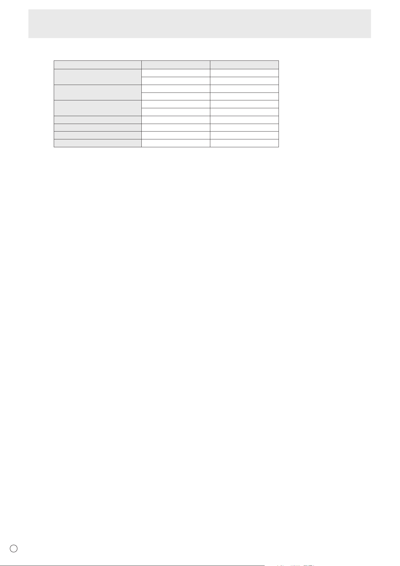
44
E
n
Compatible signal timing (AV)
Screen resolution Frequency HDMI
1920 × 1080p 50Hz Yes
60Hz Yes
1920 × 1080i 50Hz Yes
60Hz Yes
1280 × 720p 50Hz Yes
60Hz Yes
720 × 576p 50Hz Yes
720 × 480p 60Hz Yes
720(1440) × 576i 50Hz Yes
720(1440) × 480i 60Hz Yes
Specications
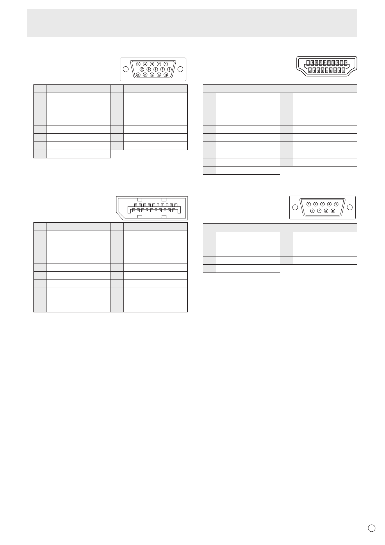
45
E
n
D-sub input terminal pins
(Mini D-sub 15 pin)
No. Function No. Function
1 Red video signal input 9 +5V
2 Green video signal input 10 GND
3 Blue video signal input 11 N.C.
4 N.C. 12 DDC data
5 GND 13 Hsync signal input
6 GND for red video signal 14 Vsync signal input
7 GND for green video signal 15 DDC clock
8 GND for blue video signal
n
DisplayPort input terminal pins
(DisplayPort 20 pin)
No. Function No. Function
1 MainLane 3- 11 Gnd
2 Gnd 12 MainLane 0+
3 MainLane 3+ 13 Gnd
4 MainLane 2- 14 Gnd
5 Gnd 15 Aux +
6 MainLane 2+ 16 Gnd
7 MainLane 1- 17 Aux -
8 Gnd 18 Hot-plug detection
9 MainLane 1+ 19 Gnd
10 MainLane 0- 20 3.3V
n
HDMI input terminal pins
(HDMI Connector)
No. Function No. Function
1 TMDS data 2+ 11 TMDS clock shield
2 TMDS data 2 shield 12 TMDS clock-
3 TMDS data 2- 13 CEC
4 TMDS data 1+ 14 N.C.
5 TMDS data 1 shield 15 SCL
6 TMDS data 1- 16 SDA
7 TMDS data 0+ 17 DDC/CEC GND
8 TMDS data 0 shield 18 +5V
9 TMDS data 0- 19 Hot-plug detection
10 TMDS clock+
n
RS-232C input terminal pins
(D-sub 9 pin)
No. Function No. Function
1 N.C. 6 N.C.
2 Transmitted data 7 N.C.
3 Received data 8 N.C.
4 N.C. 9 N.C.
5 GND
Specications

46
E
Information on the software license for this product
n
Software composition
The software included in this product is comprised of various software components whose individual copyrights are held by
SHARP or by third parties.
This product also makes use of freely distributed software and software components whose copyrights are held by third parties.
n
Software copyrights
The copyrights of some software components incorporated in the monitor require that the license be displayed. The licenses of
these software components are shown below.
uIP Embedded TCP/IP Stack
Copyright (c) 2001-2006, Adam Dunkels.
Copyright (c) 2004-2006, Swedish Institute of Computer Science.
All rights reserved.
Redistribution and use in source and binary forms, with or without modication, are permitted provided that the following
conditions are met:
1. Redistributions of source code must retain the above copyright notice, this list of conditions and the following disclaimer.
2. Redistributions in binary form must reproduce the above copyright notice, this list of conditions and the following disclaimer in
the documentation and/or other materials provided with the distribution.
3. Neither the name of the Institute nor the names of its contributors may be used to endorse or promote products derived from
this software without specic prior written permission.
THIS SOFTWARE IS PROVIDED BY THE INSTITUTE AND CONTRIBUTORS “AS IS” AND ANY EXPRESS OR IMPLIED
WARRANTIES, INCLUDING, BUT NOT LIMITED TO, THE IMPLIED WARRANTIES OF MERCHANTABILITY AND FITNESS
FOR A PARTICULAR PURPOSE ARE DISCLAIMED. IN NO EVENT SHALL THE INSTITUTE OR CONTRIBUTORS BE
LIABLE FOR ANY DIRECT, INDIRECT, INCIDENTAL, SPECIAL, EXEMPLARY, OR CONSEQUENTIAL DAMAGES (INCLUDING,
BUT NOT LIMITED TO, PROCUREMENT OF SUBSTITUTE GOODS OR SERVICES; LOSS OF USE, DATA, OR PROFITS;
OR BUSINESS INTERRUPTION) HOWEVER CAUSED AND ON ANY THEORY OF LIABILITY, WHETHER IN CONTRACT,
STRICT LIABILITY, OR TORT (INCLUDING NEGLIGENCE OR OTHERWISE) ARISING IN ANY WAY OUT OF THE USE OF
THIS SOFTWARE, EVEN IF ADVISED OF THE POSSIBILITY OF SUCH DAMAGE.
SIL Open Font License
“Noto Mono” and “Noto Sans CJK JP”
licensed under the SIL Open Font License http://www.google.com/get/noto/#/
The Atmel
®
Software Framework (ASF)
Copyright (c) 2009-2016 Atmel Corporation. All rights reserved.
Redistribution and use in source and binary forms, with or without modication, are permitted provided that the following
conditions are met:
1. Redistributions of source code must retain the above copyright notice, this list of conditions and the following disclaimer.
2. Redistributions in binary form must reproduce the above copyright notice, this list of conditions and the following disclaimer in
the documentation and/or other materials provided with the distribution.
3. The name of Atmel may not be used to endorse or promote products derived from this software without specic prior written
permission.
4. This software may only be redistributed and used in connection with an Atmel microcontroller product.

47
E
THIS SOFTWARE IS PROVIDED BY ATMEL “AS IS” AND ANY EXPRESS OR IMPLIED WARRANTIES, INCLUDING, BUT
NOT LIMITED TO, THE IMPLIED WARRANTIES OF MERCHANTABILITY, FITNESS FOR A PARTICULAR PURPOSE AND
NON-INFRINGEMENT ARE EXPRESSLY AND SPECIFICALLY DISCLAIMED. IN NO EVENT SHALL ATMEL BE LIABLE
FOR ANY DIRECT, INDIRECT, INCIDENTAL, SPECIAL, EXEMPLARY, OR CONSEQUENTIAL DAMAGES (INCLUDING,
BUT NOT LIMITED TO, PROCUREMENT OF SUBSTITUTE GOODS OR SERVICES; LOSS OF USE, DATA, OR PROFITS;
OR BUSINESS INTERRUPTION) HOWEVER CAUSED AND ON ANY THEORY OF LIABILITY, WHETHER IN CONTRACT,
STRICT LIABILITY, OR TORT (INCLUDING NEGLIGENCE OR OTHERWISE) ARISING IN ANY WAY OUT OF THE USE OF
THIS SOFTWARE, EVEN IF ADVISED OF THE POSSIBILITY OF SUCH DAMAGE.
ARM
®
Cortex
®
Microcontroller Software Interface Standard (CMSIS)
“CMSIS Core Support and CMSIS DSP Include Files” and “CMSIS DSP Libraries”
Copyright (C) 2009-2014 ARM Limited. All rights reserved.
Redistribution and use in source and binary forms, with or without modication, are permitted provided that the following
conditions are met:
- Redistributions of source code must retain the above copyright notice, this list of conditions and the following disclaimer.
- Redistributions in binary form must reproduce the above copyright notice, this list of conditions and the following disclaimer in
the documentation and/or other materials provided with the distribution.
- Neither the name of ARM LIMITED nor the names of its contributors may be used to endorse or promote products derived
from this software without specic prior written permission.
THIS SOFTWARE IS PROVIDED BY THE COPYRIGHT HOLDERS AND CONTRIBUTORS “AS IS” AND ANY EXPRESS
OR IMPLIED WARRANTIES, INCLUDING, BUT NOT LIMITED TO, THE IMPLIED WARRANTIES OF MERCHANTABILITY
AND FITNESS FOR A PARTICULAR PURPOSE ARE DISCLAIMED. IN NO EVENT SHALL THE COPYRIGHT OWNER OR
CONTRIBUTORS BE LIABLE FOR ANY DIRECT, INDIRECT, INCIDENTAL, SPECIAL, EXEMPLARY, OR CONSEQUENTIAL
DAMAGES (INCLUDING, BUT NOT LIMITED TO, PROCUREMENT OF SUBSTITUTE GOODS OR SERVICES; LOSS OF
USE, DATA, OR PROFITS; OR BUSINESS INTERRUPTION) HOWEVER CAUSED AND ON ANY THEORY OF LIABILITY,
WHETHER IN CONTRACT, STRICT LIABILITY, OR TORT (INCLUDING NEGLIGENCE OR OTHERWISE) ARISING IN ANY
WAY OUT OF THE USE OF THIS SOFTWARE, EVEN IF ADVISED OF THE POSSIBILITY OF SUCH DAMAGE.
Information on the software license for this product
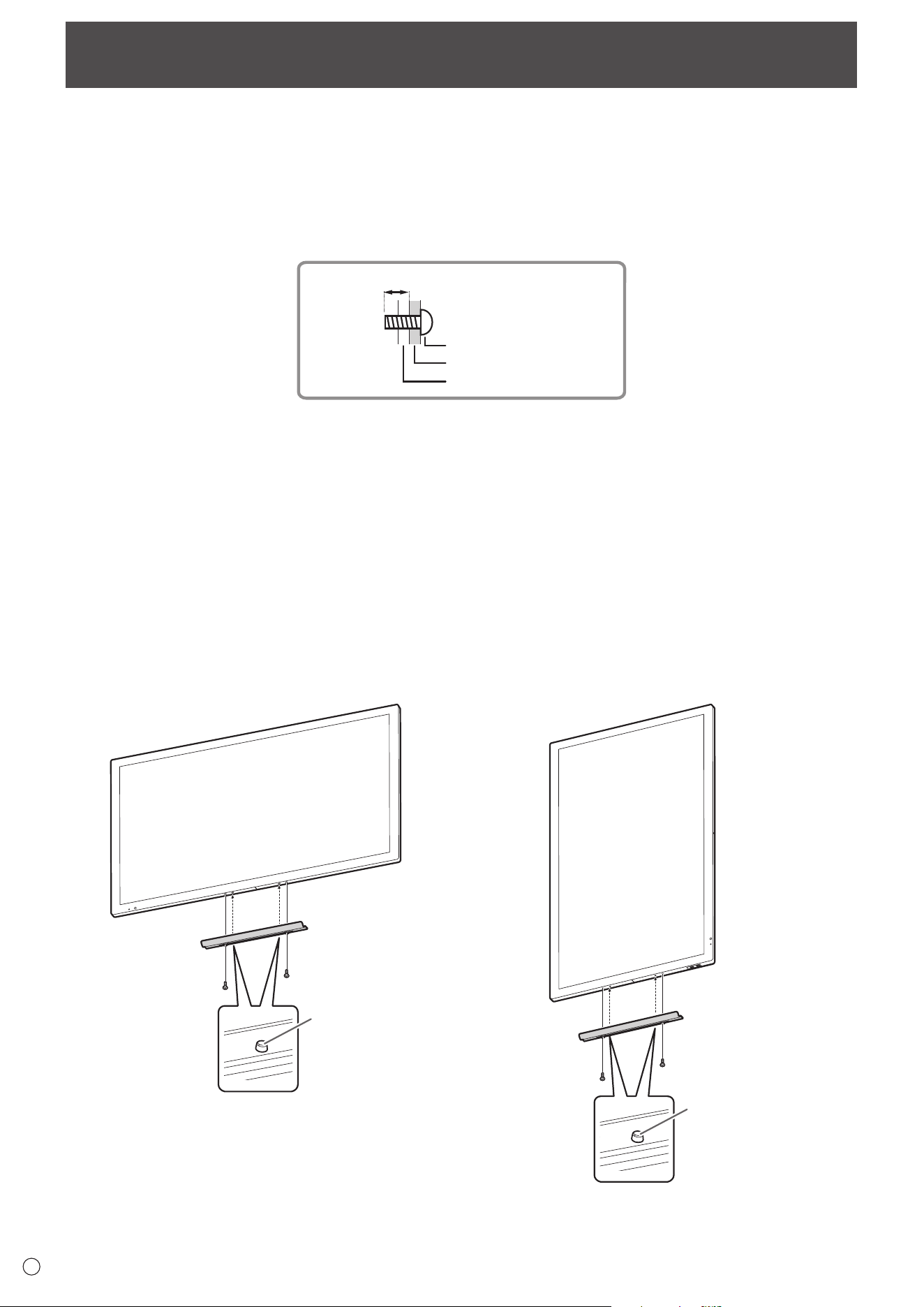
48
E
• When installing, removing or moving the monitor, ensure that this is carried out by at least 2 people.
• Be sure to use a wall-mount bracket designed or designated for mounting the monitor.
• This monitor is designed to be installed on a concrete wall or pillar. Reinforced work might be necessary for some materials
such as plaster / thin plastic board / wood before starting installation.
This monitor and bracket must be installed on a wall which can endure at least 4 times or more the weight of the monitor.
Install by the most suitable method for the material and the structure.
• To attach a VESA-compliant mounting bracket, use M6 screws that are 3/8 inch (10 mm) to 1/2 inch (12 mm) longer than the
thickness of the mounting bracket.
Screws (M6)
Mounting bracket
Monitor mounting
3/8 - 1/2 inch (10-12 mm)
• Do not use an impact driver.
• After mounting, please carefully ensure the monitor is secure, and not able to come loose from the wall or mount.
• Do not use any screw holes other than VESA holes for installation.
• When moving the monitor, be sure to hold it around the periphery. Do not grasp the screen or tray. This may cause product
damage, failure, or injury.
• If you need to temporarily place the monitor on a table or other surface during installation, spread a thick soft cloth on the
table to prevent damage to the screen and table.
• Prior to repacking or removal, remove the tray.
Mounting Precautions
(For SHARP dealers and service engineers)
n
Attaching the Tray
Secure the tray using 2 tray mounting screws (M3) (supplied).
Landscape orientation
Insert tab into
hole to secure
Portrait orientation
Insert tab into
hole to secure

PN-L501C M EN17M(1)

