78684
USER GUIDE
for Windows
®
JS PRODUCTS, INC.
|
6445 MONTESSOURI STREET
|
LAS VEGAS, NV 89113
800.255.7011 | FAX: 775.898.8773 | WWW.STEELMANPRO.COM
Made in China
The Steelman
®
PRO CHASSISEAR
®
-NVH is
backed by a 90 Day Warranty. This warranty
covers manufacturer defects and
workmanship. The warranty excludes misuse
or abuse and normal wear and tear. Exclusion
is not allowed in some states and may not
apply. This warranty gives you specific legal
rights, and you may have other rights, which
vary from state to state.
This device complies with part 15 of the FCC Rules Operation is subject to the following two conditions:
(1) This device may not cause harmful interference, and (2) this device must accept any interference received, including interference that may cause
undesired operation.
This equipment has been tested and found to comply with the limits for a Class B digital device, pursuant to part 15 of the FCC Rules. These limits are
designed to provide reasonable protection against harmful interference in a residential installation. This equipment generates, uses and can radiate radio
frequency energy, and if not installed and used in accordance with the instructions, may cause harmful interference to radio communication. However,
there is no guarantee that the interference will not occur in a particular installation. If this equipment does cause harmful interference to radio or
television reception, which can be determined by turning the equipment off and on, the user is encouraged to try to correct the interference by one or more
of the following measures:
• Reorient or relocate the receiving antenna
• Increase the separation between the equipment and receiver
• Connect the equipment into an outlet on a circuit different from that to which the receiver is connected
• Consult the dealer or an experienced radio/TV technician for help
Designed in Las Vegas, NV
Windows is a registered trademark of Microsoft Corporation in the United States and other countries.
The Bluetooth
®
word mark and logos are registered trademarks owned by Bluetooth SIG, Inc. and any use of such
marks by JS Products, Inc. is under license. Other trademarks and trade names are those of their respective owners.
Windows 7 Windows 8
Patent Pending
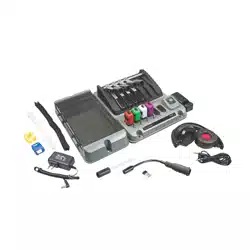
SENSOR
CLAMPS
BLUETOOTH
®
DONGLE
STORAGE
COMPARTMENT
BLUETOOTH
®
MODULE
DOCKING
STATION
DOCKING
STATION
CHARGER
HEADPHONES
SOUND
WAND
SOUND
PROBE


TABLE OF CONTENTS
Installation of Software
Initializing Program and Interface Window
Pairing Bluetooth
®
Modules
Interface Help and User Information
Orientation Display Mode
View Mode
Graph Mode
Ambient Sound Reset, Offset, and Channel Selection
Settings
Equalizer
Assigning Clamp Locations
Removing Custom Clamp Locations
Isolating Specific Sounds Using FFT Graph and Equalizer
File Recording
File Playback
File Sharing and Changing File Name
Deleting Recordings
Charging Instructions
1
2
3
4
5
6
7
8
9
10
11
12
13
14
15
16
17
18

18
1
• Download BlueSoleil driver zipped file and the CHASSISEAR
®
-NVH app at:
steelmanpro.com/bt-chassisear
• Make sure you have administrative rights during installation
• Connect USB Bluetooth
®
Dongle
• Unzip the BlueSoleil driver
• Run setup from Unzipped Directory/BlueSoleil Driver/Install. Follow the instructions to install the
BlueSoleil Driver. After Driver install, it may be necessary to restart your device/computer.
• Run the CHASSISEAR
®
-NVH setup file, this will install CHASSISEAR
®
-NVH
• Return to the Quick Set-up Guide instructions, Step 7
Installation of Software
Charging Instructions
To charge the Bluetooth
®
Modules, use the 5VDC 2A wall charger. Plug the 5.5mm male plug into
the back of the Docking Station. The BLUE light indicator should light up to indicate that the
Docking Station has power. Next, plug in the Bluetooth
®
Modules into the Docking Station. The
GREEN indicator lights should light up indicating that the Bluetooth
®
Modules are charging. Once
the Bluetooth
®
Modules are fully charged, the GREEN indicator lights should dim down indicating
that the Bluetooth
®
Modules are in standby mode and ready for use. Allow 2-3 hours for the
Bluetooth
®
Modules to charge for the first time to ensure that they are fully charged.
17
2
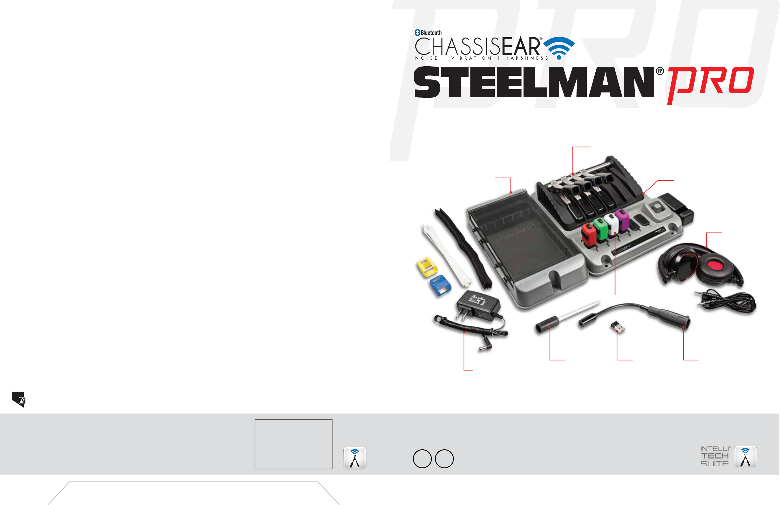
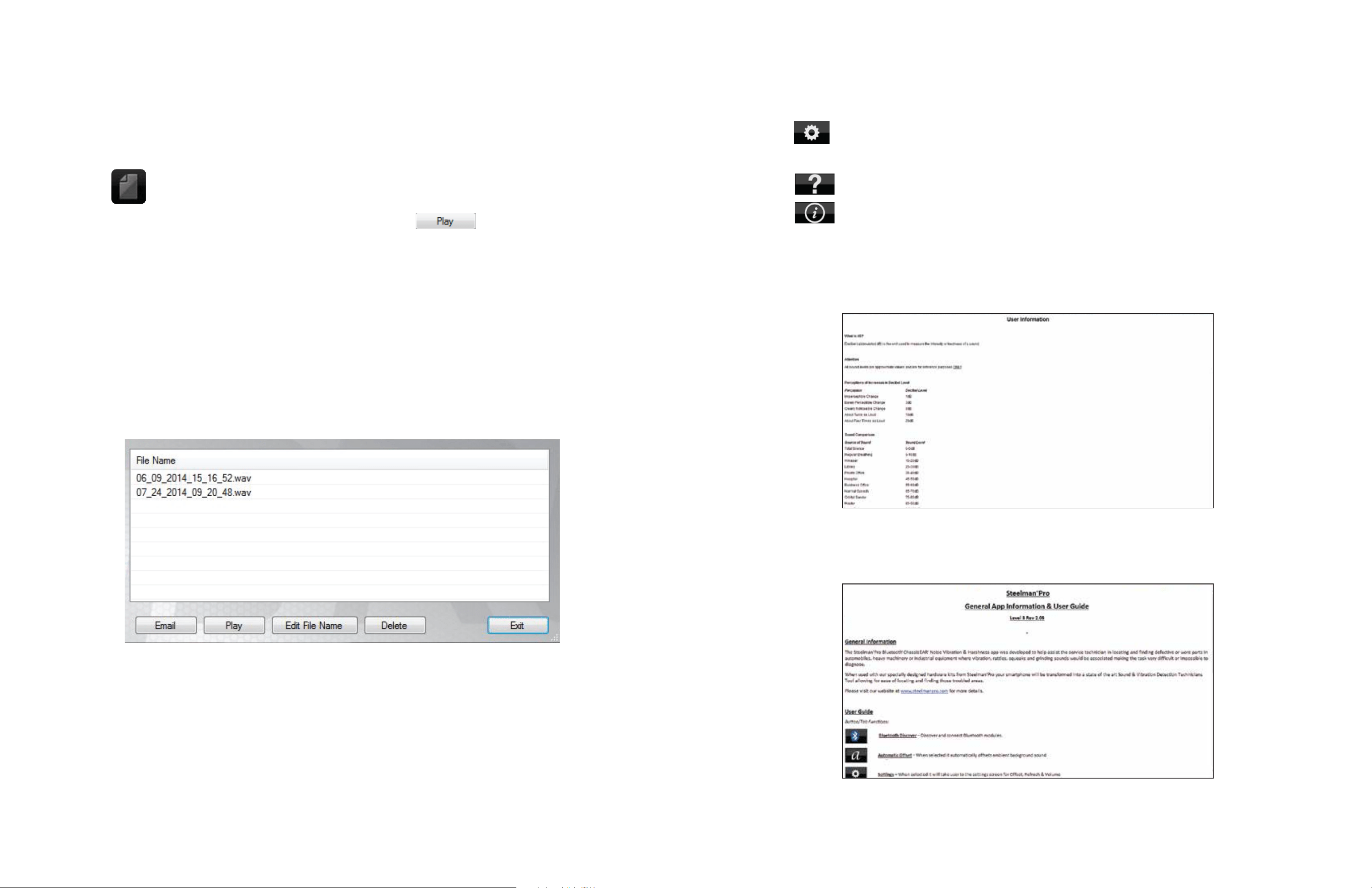
SAVED RECORDINGS AND
RECORDING PLAYBACK WINDOW
• From the saved recordings screen, events can be selected by clicking on the text area of
the file name
• The text background will be highlighted
• Click the button to delete the selected recording and then click
Deleting Recordings
• To initiate application, click the Steelman
®
PRO CHASSISEAR
®
-NVH shortcut from the
desktop of your
Windows
®
device
• Once the application has finished loading, it will take you to the user interface where the user will
be able to navigate throughout the application
Initializing Program and Interface Window
USER INTERFACE
16
3
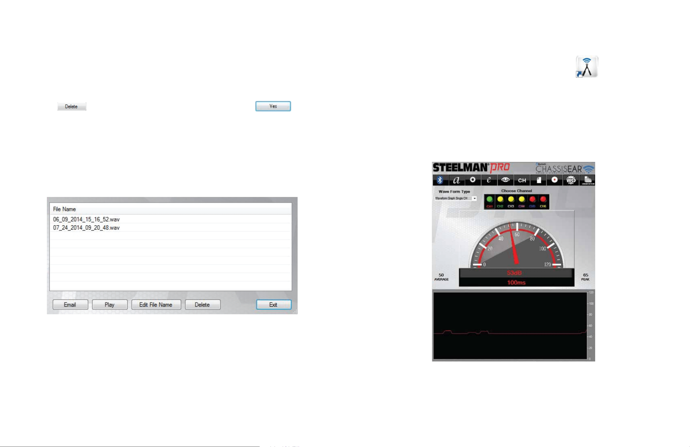
FILE SHARING WINDOW
• To change the file name of the event, select to highlight the event to be renamed and click the
button. Type the new name of the file and click the button.
• To share a file, simply click the button option, populate the
“TO:” field, and hit send
NOTE: The default file name for saved files will be a time and date stamp
File Sharing and Changing File Name
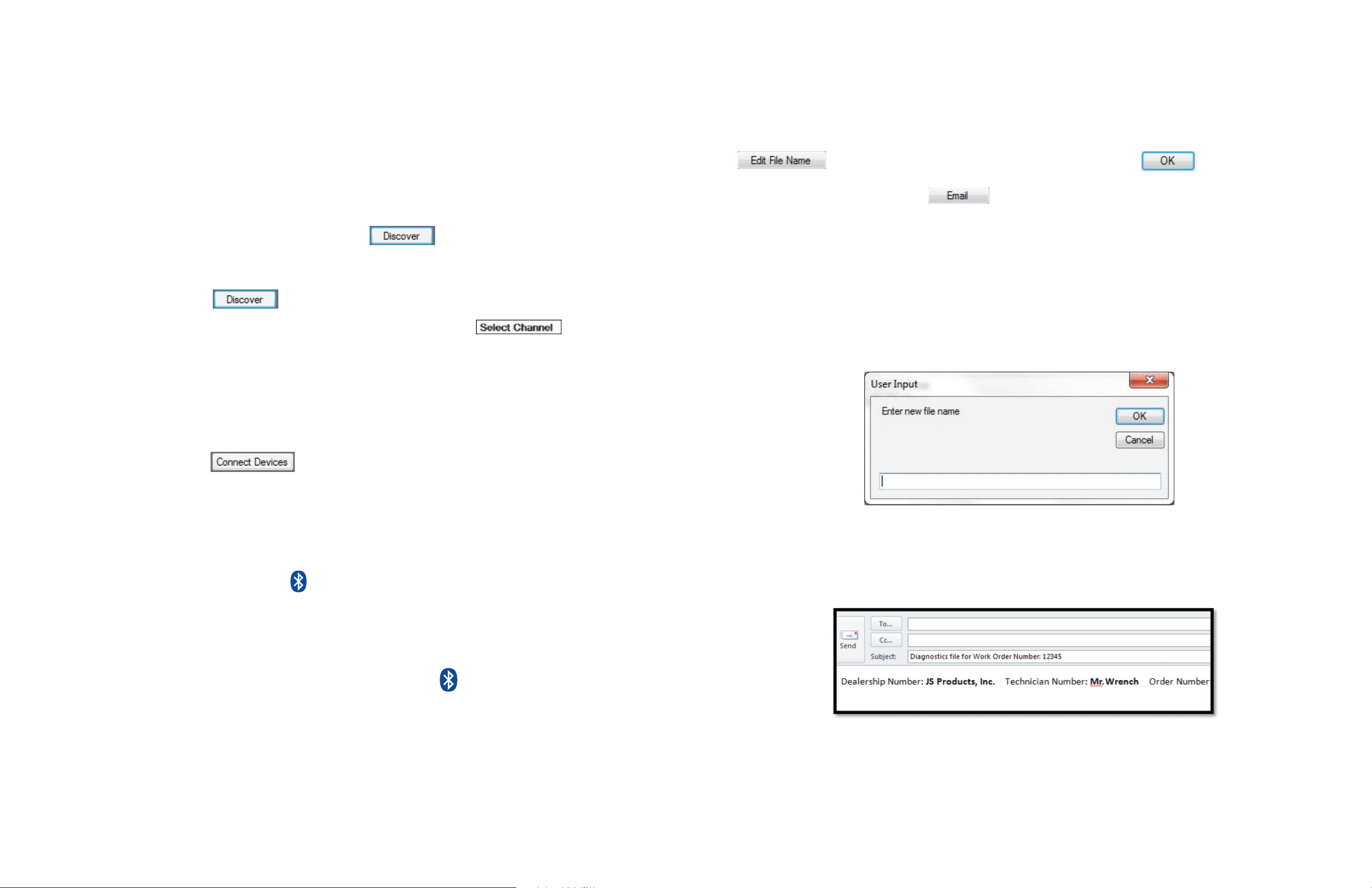
• Switch power on for Bluetooth
®
Module by inserting into either the Sound Wand or Sensor Clamps.
Ensure Modules are fully charged before each use.
NOTE: The lights on the Bluetooth
®
Modules will flash RED and BLUE intermittently to show the
Modules are powered on, and app is initiated
• A Bluetooth
®
Setup window will pop up. Click on the button to initiate pairing. A list of
discoverable devices will appear. For ease of pairing, each Bluetooth
®
Module has its serial
number printed on the back. It may take up to 15 seconds to have all powered Bluetooth
®
Modules
show up after clicking the button.
• Next, designate a channel for each Bluetooth
®
Module by clicking the box next to
the device name. A drop-down box of channels will appear where each Module will be assigned its
own color code. At this point, each Module can be fitted with the corresponding Color Boot for each
channel, if not done so already. Each channel has been given a predetermined color: Channel 1 is
RED, Channel 2 is GREEN, Channel 3 is WHITE, and Channel 4 is PURPLE.
• Once each Bluetooth
®
Module has been assigned a designated channel, they can be connected to
the device by clicking the button. In addition, the Bluetooth
®
Module lights will
begin flashing BLUE intermittently.
• If connection is successful, the “Choose Audio Output” window will appear
• Choose an Audio Output preference. You may select either PC speakers or headphones. If sound is
not working on the selected audio output, you must re-pair the devices and choose another audio
device. Re-pair devices by clicking the button and follow the steps from the beginning of this
page (to start re-pairing, the user must disconnect the Bluetooth
®
Modules and then reconnect to
begin the pairing process again).
• After initial setup, each time the software is restarted, it will automatically reconnect old pairings
• If the user would like to rediscover Bluetooth
®
devices, click the button
• Return to Quick Set-up Guide to complete setup, Step 8.
Pairing Bluetooth
®
Modules
4
15
• Click the button in the menu toolbar of the user interface to access refresh rate, offset, and
volume controls
• Click the button from the settings screen for the HELP window
• Click the button from the settings screen for the INFORMATION window
• These screens display additional reference information for sound comparison and tips on use of
the application
Interface Help and User Information
SAVED RECORDINGS AND
RECORDING PLAYBACK WINDOW
• Once you have finished recording, you then have the ability to review your sound file that was
automatically saved to the
Windows
®
device
• Click the button to access all sound files
• To play back an event, highlight the file name and click the button
• Files can be played back to review, get a second opinion, or can be sent to the customer to verify
that the noise is being diagnosed correctly
File Playback
HELP WINDOW
INFORMATION WINDOW
5
14
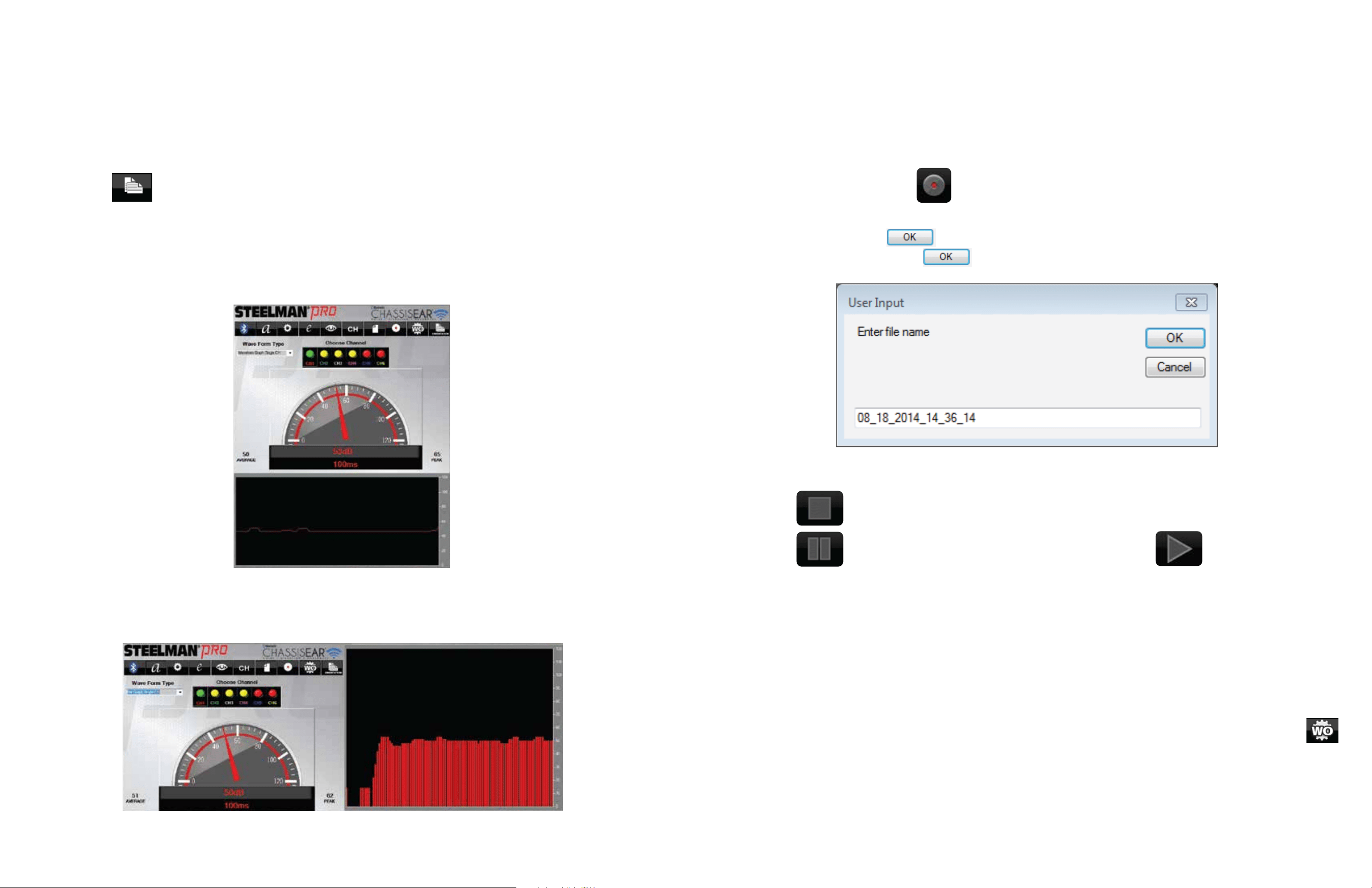
• From the user interface during a test drive or diagnostic test, the event can be recorded and will
automatically save to memory on the saved recordings page (see page 16)
• To record the event, click the button on the user interface
• The user input window will appear with a time date stamp. If the user is ok with this name for
their testing event, click . If the user desires to rename the file; simply click on the text
box, rename the file, and click .
• Click the button to stop while recording (this will end recording the event)
• Click the button to pause recording the event, and click the button to resume
recording the event
• The files can be played back immediately, archived to build a database, shared with another
technician, or emailed to a customer as confirmation that a repair is needed or that one has
been completed
• Tests can be recorded for an unlimited amount of time
• A Work Order form may be used to populate specific information related to a customer’s
automobile for ease of reference. This information can be populated and saved by clicking the
button. Once saved, this information will be populated in an email for any test event. The Work
Order information must be repopulated and saved for each subsequent test if the user wishes to
include this information in a recorded test event which will be emailed.
NOTE: Channels cannot be switched during recording
File Recording
LANDSCAPE
PORTRAIT
Orientation Display Mode
• Select the desired orientation display mode. There are two orientation display modes:
Portrait and Landscape
• Click the button to change between display modes
NOTE: The default display mode is Landscape
NOTE: Some screen resolutions are not supported
USER INPUT
13 6
DIGITAL GAUGE
ANALOG GAUGE
FFT GRAPH
EQUALIZER
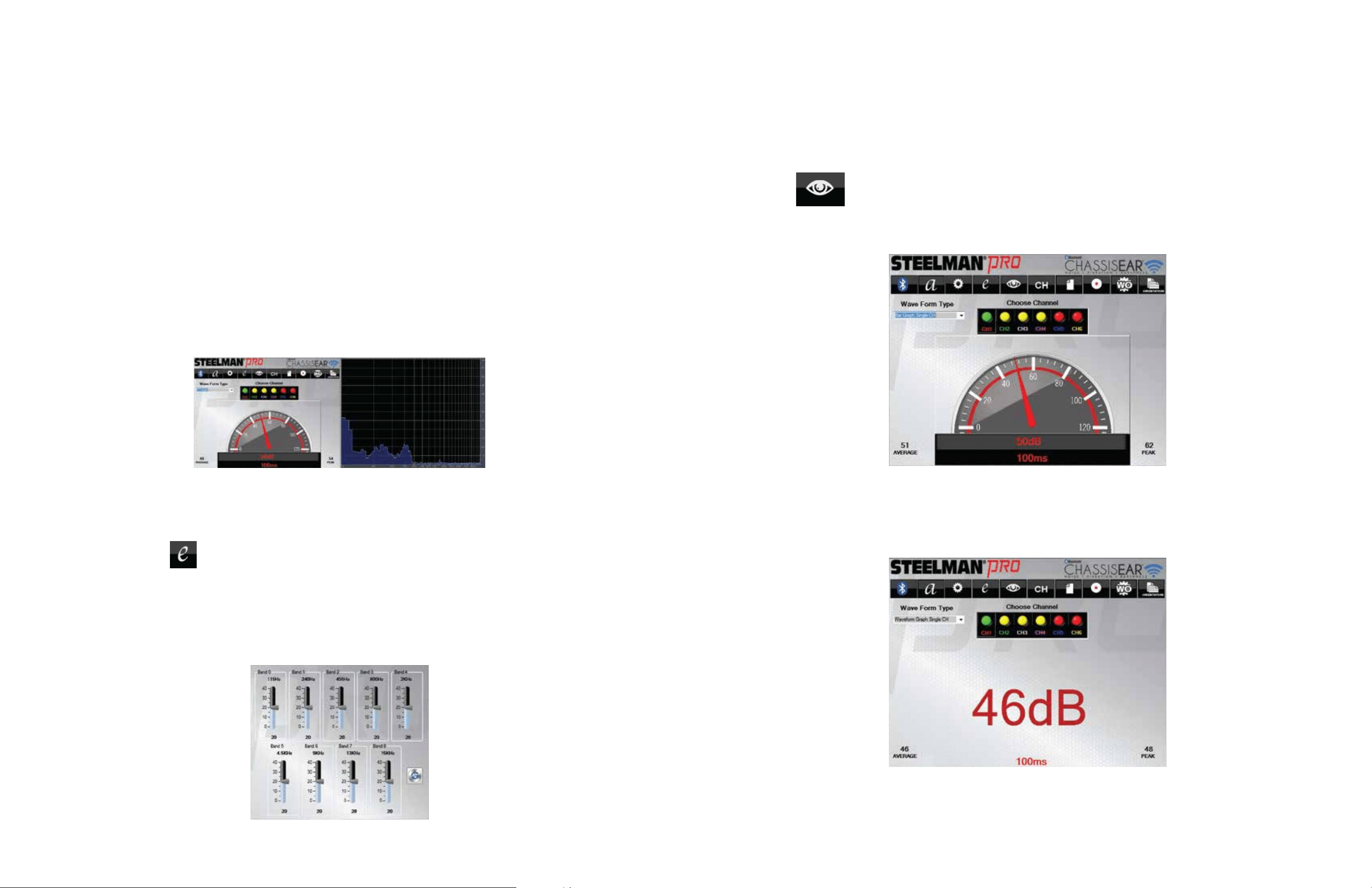
• After selecting the Orientation Mode, select the desired viewing mode. There are two
viewing modes: Analog and Digital
• Click the button to change between views
View Mode
FPO
• Using a combination of the graphing features and the equalizer allows Steelman
®
PRO
CHASSISEAR
®
-NVH to enhance or mute specific sounds. By isolating frequencies, sounds that you
want to hear can be enhanced, while other sounds can be eliminated.
• To isolate sounds, select FFT Graph from the Wave Form Type dropdown menu on the user
interface. The FFT Graph displays the entire spectrum of sound on the active channel. The
horizontal axis of the graph shows which frequency a particular sound occupies. The vertical axis
shows the decibel level of the sound. The highest point on the graph indicates the frequency with
the most prominent sound.
• Using data from the FFT Graph, the equalizer can be used to hone in on sounds. On the User
Interface, click the button. In a separate window, the equalizer will open.
• Each slider on the equalizer represents a range of sound frequency that can be amplified or
reduced. Based on the frequency you identified on the FFT graph, manipulate the sliders until
other noises are eliminated and the sound you want to listen more closely to is the only sound you
can hear.
Isolating Specific Sounds Using FFT Graph
and Equalizer
7
12
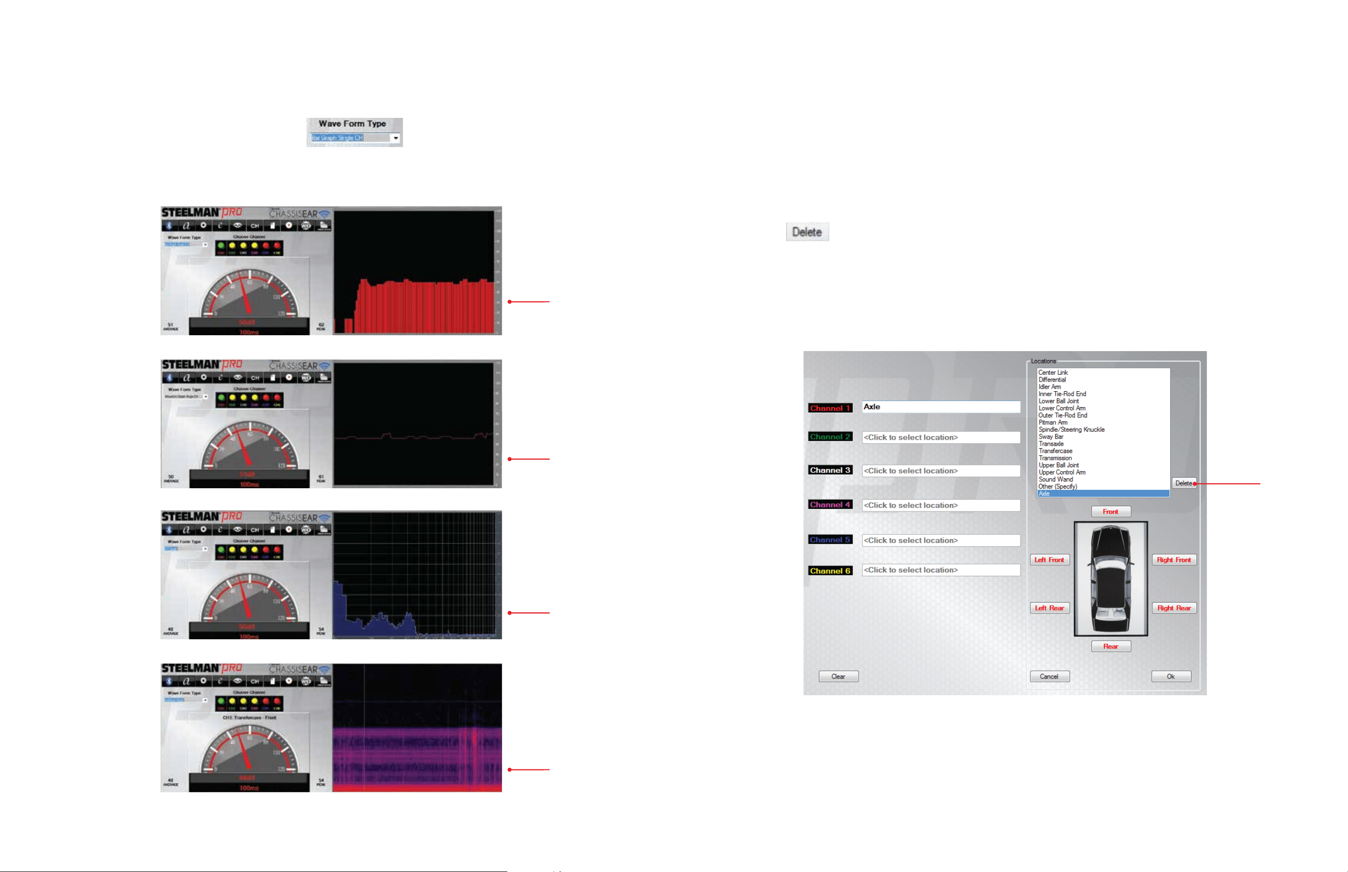
• To select the desired graph mode click the menu button. There are 4 graph types:
Bar, Waveform, FFT, and Spectrum
Graph Mode
BAR
WAVEFORM
FFT
SPECTRUM
DELETE ENTRY WINDOW
• Custom location descriptions are saved to the pull down menu automatically and placed in
alphabetical order
• If desired, custom location descriptions can also be deleted from the pull down menu if
no longer needed
• Click the button for the corresponding position that needs to be deleted from the
locations list
Removing Custom Clamp Locations
DELETE
8
11
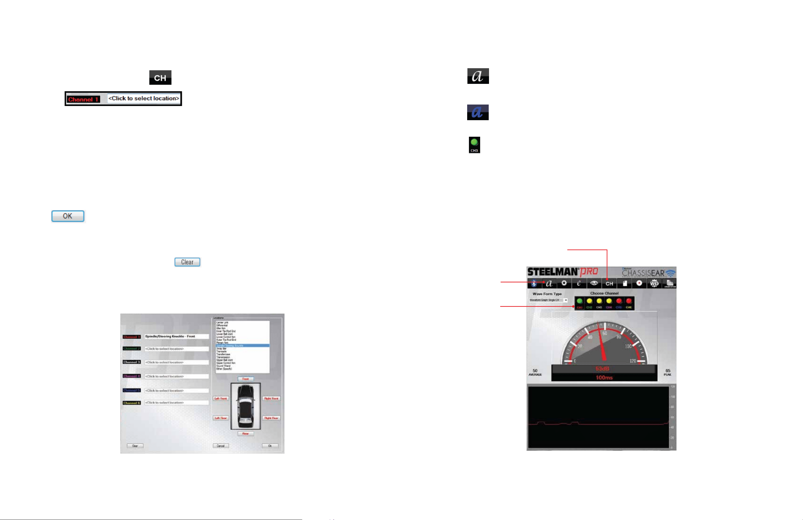
USER INTERFACE
• Click the button for ambient sound reset (this is recommended for areas where there is
excess or disruptive background noise)
• Click the button again for ambient sound offset (this will restore sound settings to
location when originally powered)
• Click the button for the desired channel for the corresponding clamp that you would like to
listen to and see visual output for
NOTE: GREEN indicates the channel is active and sound and visual output will occur on your device.
YELLOW indicates the channel is connected with a Bluetooth
®
Module but in Standby mode.
RED indicates the channel does not have a Bluetooth
®
Module connected.
Ambient Sound Reset, Offset, and Channel Selection
AMBIENT
OFFSET/RESET
CHANNEL
SELECTION
CHANNEL
LOCATION
SETUP
• From the user interface, click the button to access the channel location setup window
• Click the text box to access the location assignment window
for Clamp 1
• Click the text box again on the location assignment window to the right to access
preloaded locations
• You may create a custom location by scrolling to the bottom of the list and selecting Other (specify)
• Once a specific location has been selected or created from the Other (specify) selection, click on the
general location of the clamp on the location assignment window. Available locations include: Front,
Left-Front, Right-Front, Left-Rear, Right-Rear, or Rear.
• Click when desired location is set to save that location
• Create clamp locations for each of the other corresponding channels to be used in the test in the
same manner as previously described
• To reset clamp location names, click the button to clear all previously selected locations
• When finished assigning channel locations, close the window to return to the user interface
Assigning Clamp Locations
CHANNEL LOCATION SETUP WINDOW
10
9
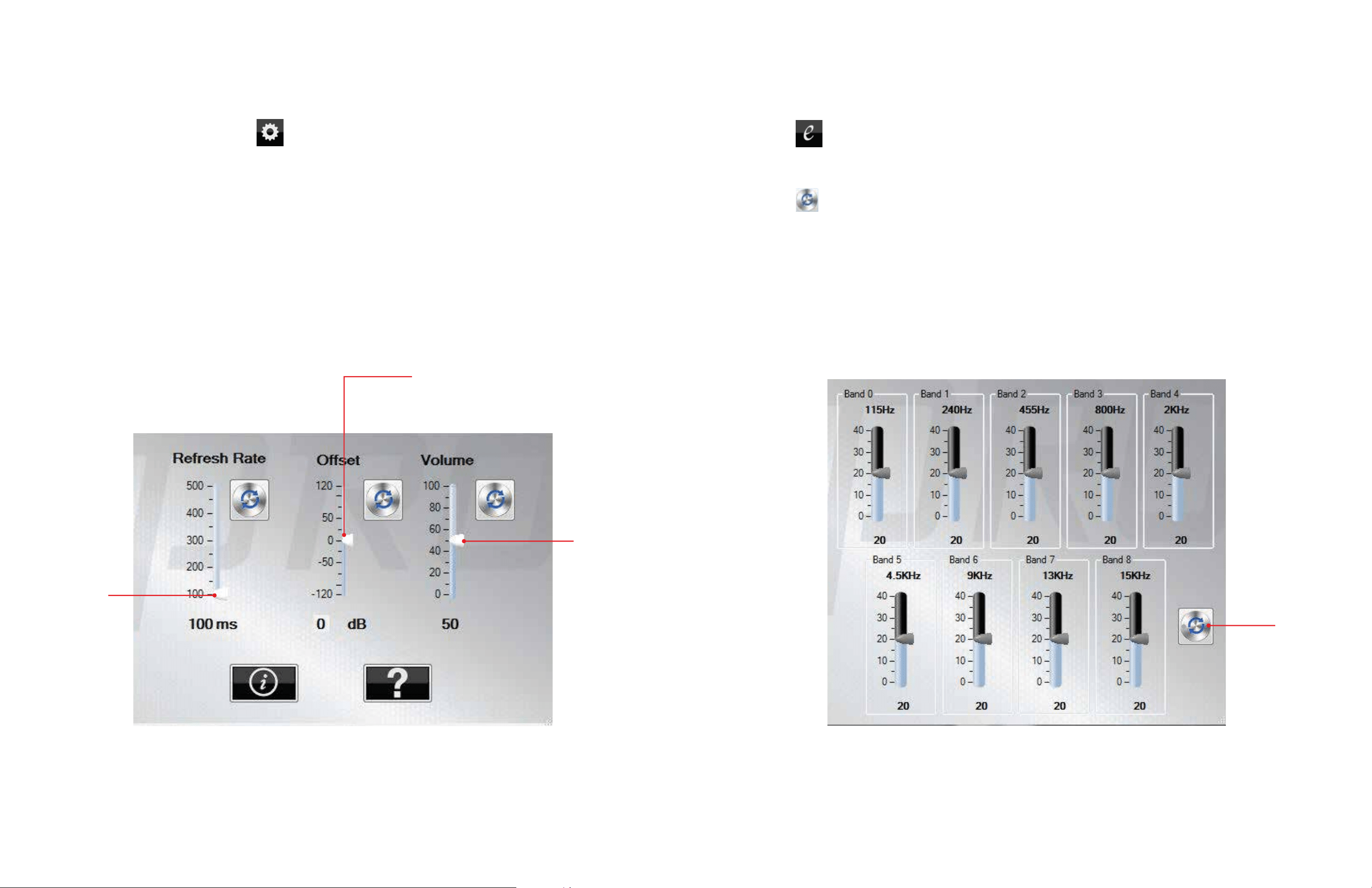
SETTINGS WINDOW
REFRESH
RATE
OFFSET
VOLUME
• From the user interface, click the button for control settings
• The refresh rate can be fine-tuned depending on how the user would like to see the output (the
higher the refresh rate the slower the visual output)
• The offset settings can be fine-tuned to the user’s specifications depending on background noise
• The volume can be adjusted manually by moving the slide bar under the volume heading
• Close the window to return to the user interface
Settings
EQUALIZER WINDOW
• Click the button to access the 9-Band Equalizer controls
• After making manual adjustments to the equalizer close the window
• Click the button to reset the equalizer to default settings
Equalizer
RESET
