
INSTALLATION GUIDE
for the
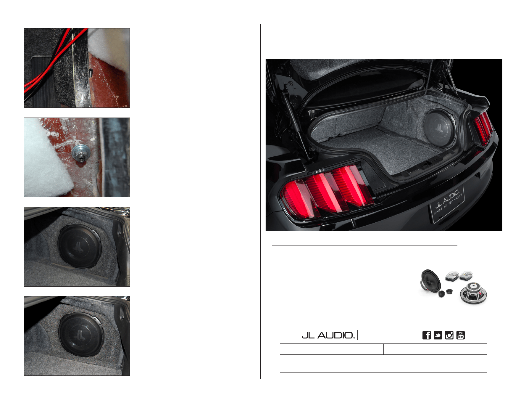
SB-F-MUSCPE/12TW3
SKU# 94617
2015 - Up Ford Mustang Coupe
Thank you for choosing a JL Audio Stealthbox® for your automotive sound system.
With proper installation, your new vehicle-specific enclosed subwoofer system
will deliver years of listening pleasure.
We strongly recommend that you have your new Stealthbox® installed by your
authorized JL Audio dealer. The installation professionals employed by your
dealer have the necessary tools and experience to disassemble and reassemble
your vehicle properly. If you prefer to perform your own installation, please read
this installation guide completely before beginning the process.
If you choose to perform the installation yourself, it is absolutely vital
that the Stealthbox
®
be properly mounted to the vehicle according to
these instructions. Failure to mount the enclosure properly presents two
problems:
1) The sub-bass performance will suffer due to the movement of the
enclosure caused by the force exerted by the woofer(s).
2) A loose enclosure presents a serious safety hazard in the event of a
collision or sudden deceleration.
INSTALLATION
DIFFICULTY:
ESTIMATED TIME:
1-2 HOURS
Enclosure Type: Sealed
Driver Type: 12TW3-D4
Nominal Impedance: 2 ohms
Continuous Power Handling: 400 watts (RMS method)
Continued on Next Page
2
5
OUT
OF
SB-F-MUSCPE/12TW3 INSTR_SKU# 011432
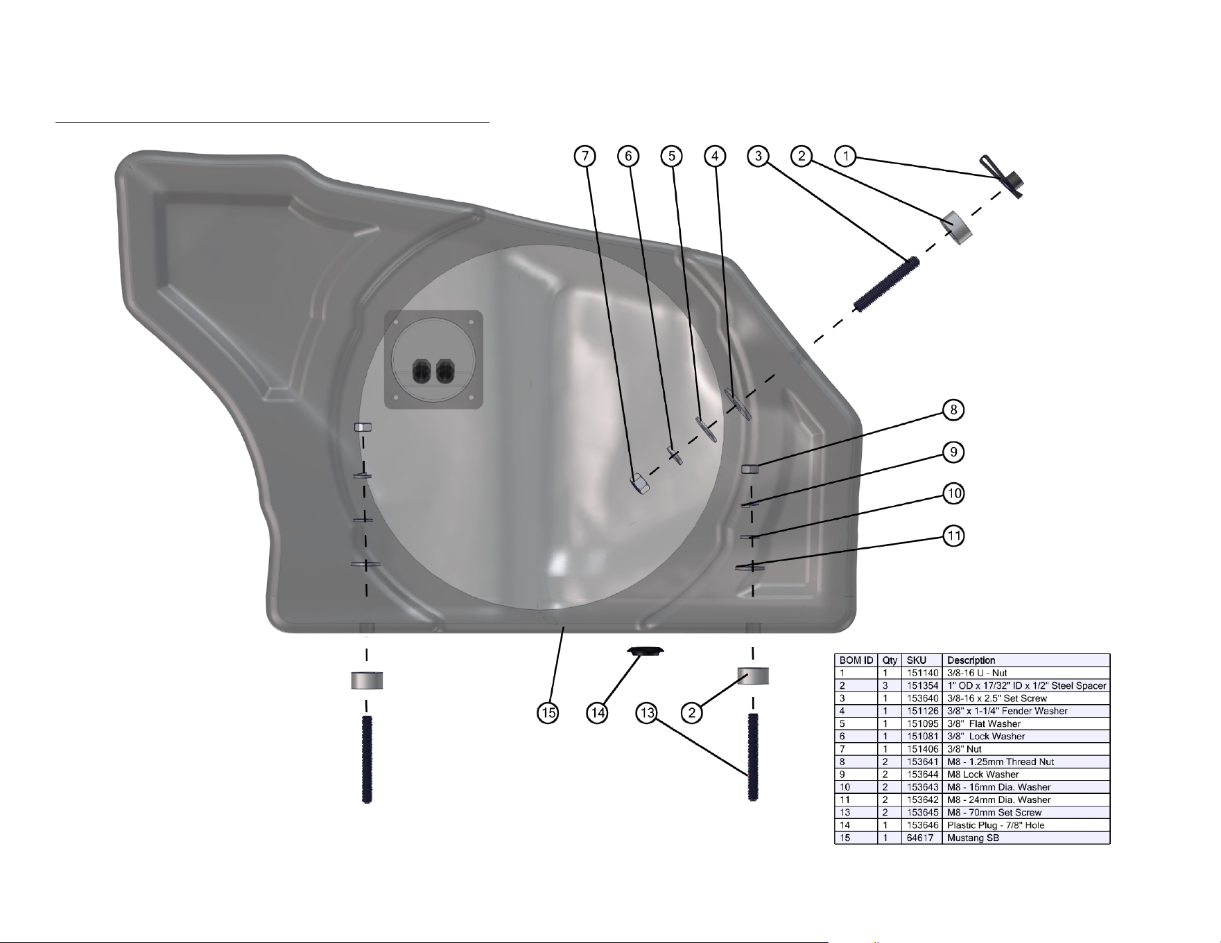
INCLUDED HARDWARE
Continued on Next Page
Page 2 • JL Audio, Inc., 2016
SB-F-MUSCPE/12TW3 INSTR_SKU# 011432
Not shown: 1 150835 Trim Panel
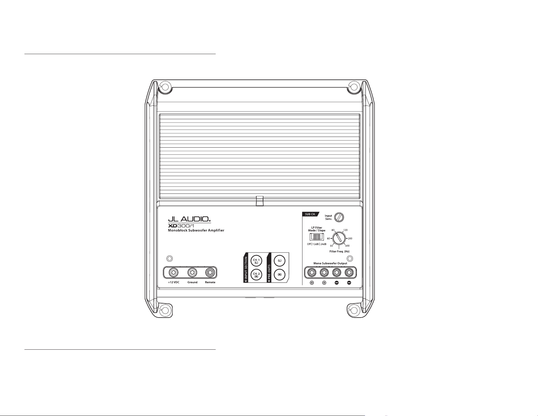
POWER RECOMMENDATION
JL Audio recommends high quality ampliers such as the JL Audio XD300/1v2. The diagram below shows the recommended crossover settings for the XD300/1v2. For a detailed description of the
amplier settings, consult the owner’s manual for the amplier. If another amplier is being used, please reference this illustration and use similar settings on that amplier.
CONNECTIONS
Using quality power, signal, and speaker wire is essential in ensuring the performance of your Stealthbox®. JL Audio recommends using a 4 AWG power kit such as the XD-PCS4-1B for your
Stealthbox® amplier. Other kits are available should you be using more than one amplier. Signal wire such as the JL Audio Premium Audio Interconnect Cables should be used to provide signal for
both channels of the amplier. JL Audio recommends using 12AWG speaker wire for subwoofers such as our XC-BCS12-25.
Continued on Next Page
Page 3 • JL Audio, Inc., 2016
SB-F-MUSCPE/12TW3 INSTR_SKU# 011432
Page 4 • JL Audio, Inc., 2016 Continued on Next Page
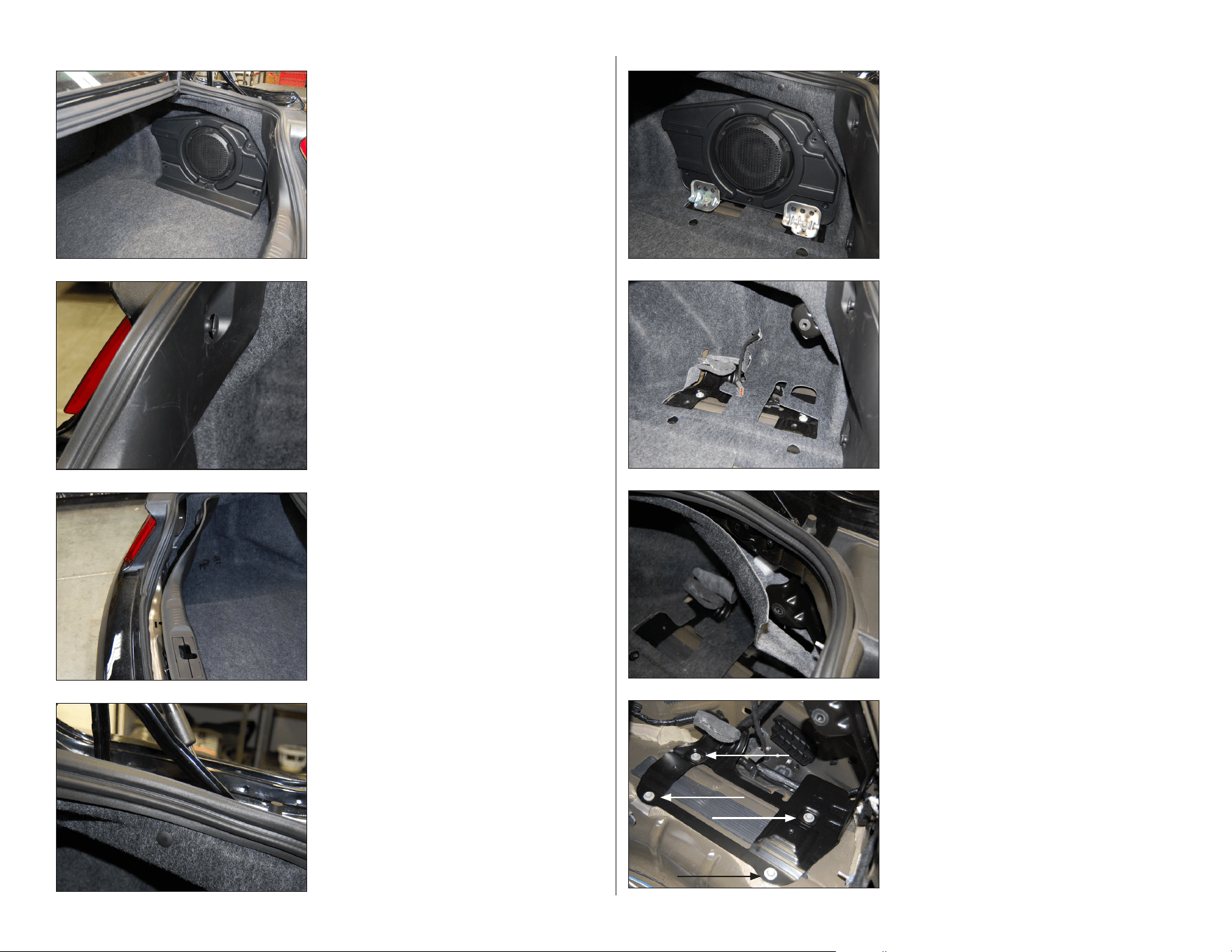
STEP 8
Remove the four indicated lower subwoofer
enclosure bracket bolts.
STEP 7
Pull the trunk liner away to gain access to the
subwoofer enclosure bracket.
STEP 6
Remove the two 13 mm bolts securing the
bottom of the factory subwoofer enclosure to
the subwoofer enclosure bracket. Remove the
T-40 Torx bolt securing the top of the factory
subwoofer enclosure to the subwoofer
enclosure bracket.
Unplug the subwoofer, and remove the
enclosure from the vehicle.
STEP 5
Note: Steps 5-13 are only necessary in
vehicles equipped with the factory
subwoofer. If vehicle does not have the
factory subwoofer, skip to Step 14.
Remove the three T-20 Torx screws securing
the lower trim panel to the factory subwoofer
enclosure, and remove the trim panel.
STEP 4
Remove the clip holding the top of the trunk
liner to the vehicle on the passenger side.
STEP 3
Carefully unclip the trunk sill panel, and
remove the panel from the vehicle.
Remove the cargo floor panel from the vehicle.
STEP 2
Remove the cargo net hooks from both sides
of the trunk sill panel.
STEP 1
Empty out the trunk of the vehicle.
Some models are not equipped with the
pictured factory subwoofer.
SB-F-MUSCPE/12TW3 INSTR_SKU# 011432
Page 5 • JL Audio, Inc., 2016 Continued on Next Page
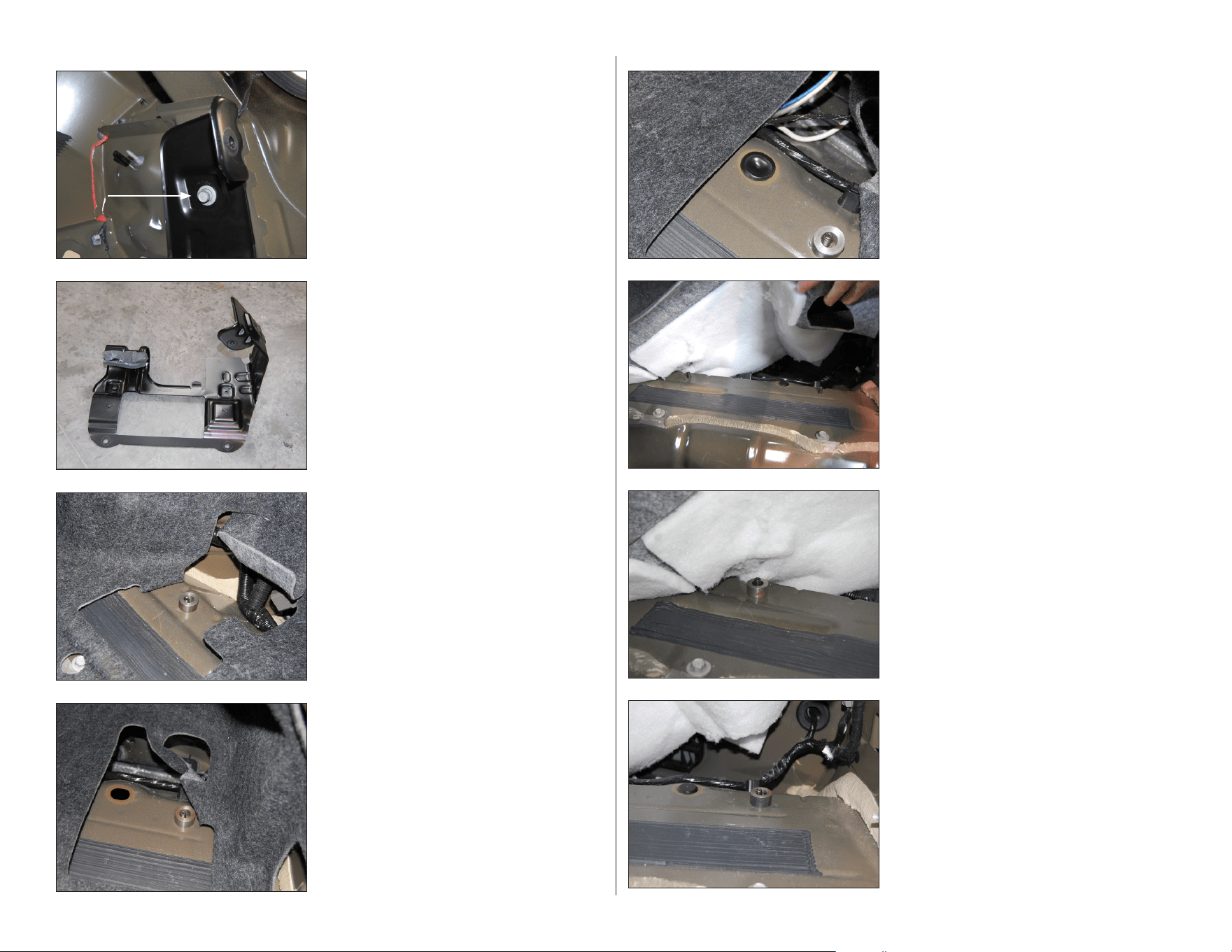
STEP 16
Thread an M8 - 70 mm Set Screw into the other
factory threaded hole. Place a 1” OD x 1/2”
Steel Spacer over the screw, and thread the M8
- 70 mm Set Screw until the top is 1/4” above
the top of the 1” OD x 1/2” Steel Spacer.
STEP 15
Thread an M8 - 70 mm Set Screw into one of
the factory threaded holes. Place a 1” OD x
1/2” Steel Spacer over the screw, and thread
the M8 - 70 mm Set Screw until the top is 1/4”
above the top of the 1” OD x 1/2” Steel Spacer.
STEP 14
Note: Steps 14-18 are only necessary in
vehicles not equipped with the factory
subwoofer. If vehicle does have the factory
subwoofer, skip to Step 19.
Lift up the trunk liner, and locate the two
factory threaded holes in the floor.
STEP 13
Press the Plastic Plug into the factory hole in
the floor.
Use a heat gun to soften the Plastic Plug,
allowing it to take the shape of the factory
hole. It may be necessary to add silicone
adhesive to hold the Plastic Plug in place.
STEP 12
Fold the trunk liner flap out of the way to
expose the other factory threaded hole in the
floor.
Thread an M8 - 70 mm Set Screw into the
factory threaded hole. Place a 1” OD x 1/2”
Steel Spacer over the screw, and thread the M8
- 70 mm Set Screw until the top is flush with
the 1” OD x 1/2” Steel Spacer.
STE P 11
Fold the trunk liner flap out of the way to
expose one of the factory threaded holes in
the floor.
Thread an M8 - 70 mm Set Screw into the
factory threaded hole. Place a 1” OD x 1/2”
Steel Spacer over the screw, and thread the M8
- 70 mm Set Screw until the top is flush with
the 1” OD x 1/2” Steel Spacer.
STEP 10
Remove the subwoofer enclosure bracket from
the vehicle.
STEP 9
Remove the indicated upper subwoofer
enclosure bracket bolt.
SB-F-MUSCPE/12TW3 INSTR_SKU# 011432
Page 6 • JL Audio, Inc., 2016 Continued on Next Page
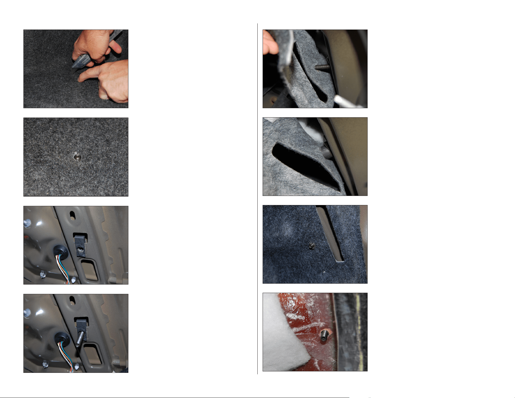
STEP 24
Remove the subwoofer from the Stealthbox®.
Connect speaker cable to the terminal cup on
the enclosure, and route the cable as
necessary.
Guide the rear of the enclosure into position
first, allowing the 3/8 - 16 x 2-1/2” Set Screw to
pass through the hole in the back of the
enclosure.
STEP 23
Pictured is the 3/8 - 16 x 2-1/2” Set Screw with
the trunk liner back in place.
STEP 22
Place a 1” OD x 1/2” Steel Spacer over the 3/8
- 16 x 2-1/2” Set Screw, press the trunk liner
down, allowing the screw to pass through the
cut made in the trunk liner in the previous step.
STEP 21
Press the top of the trunk liner down against
the 3/8 - 16 x 2-1/2” Set Screw, and cut a small
“X” in the trunk liner over the screw.
STEP 20
Thread the 3/8 - 16 x 2-1/2” Set Screw into the
3/8 - 16 U-Nut as far as it will go.
STEP 19
Note: Steps 19-27 are necessary for all
models.
Slide a 3/8 - 16 U-Nut over the hole in the brace
near the passenger side taillight harness, as
shown.
If a factory U-nut is already installed in this
location, it will need to be removed and
replaced with the 3/8 - 16 U-Nut.
STEP 18
Push the trunk liner into position, allowing the
two M8 - 70 mm Set Screws to pass through
the cuts made in the trunk liner in the previous
step.
STEP 17
Fold the trunk liner back down against the M8
- 70 mm Set Screws, and cut a small “X” in the
trunk liner over each of the screws.
SB-F-MUSCPE/12TW3 INSTR_SKU# 011432
Page 7 • JL Audio, Inc., 2016
MID/HIGH FREQUENCY DRIVER FITMENT
A variety of JL Audio coaxial and component systems will t in the factory speaker locations of you vehicle.
Front Speaker Size / Location: 6-1/2”- Front Doors
Fits JL Audio Models: TR650-CXi, TR650-CSi, C2-650x, C2-650,
C3-650, C5-650x, C5-650, & ZR650-CSi
Rear Speaker Size / Location: 6-1/2”- Rear Deck
Fits JL Audio Models: TR650-CXi, TR650-CSi, C2-650x, C2-650,
C3-650, C5-650x, C5-650, & ZR650-CSi
All specifications are subject to change without notice. “JL Audio®” and the JL Audio logo, and “Stealthbox” and the Stealthbox logo are registered trademarks of JL Audio, Inc. “Ahead of the
Curve”, its respective logo, and “How we play” are trademarks of JL Audio, Inc.
Printed in USA • ©2016 JL Audio, Inc. • For more detailed information please visit us online at www.jlaudio.com.
(954) 443-1100
www.jlaudio.com
JLA-SKU# 011432 • ver. 11.03.2016 • 10369 NORTH COMMERCE PARKWAY • MIRAMAR, FLORIDA • 33025 • USA
CONGRATULATIONS!
You have completed the installation for this model! Enjoy your new Stealthbox®!
How we play.
™
SB-F-MUSCPE/12TW3 INSTR_SKU# 011432
STEP 28
Note: Step 28 is only necessary in
vehicles equipped with the factory
subwoofer.
Secure the Trim Panel to the trunk floor in
front of the enclosure, as shown.
STEP 27
Reinstall the subwoofer. Reinstall the trunk
liner clip above the Stealthbox®. Reinstall the
trunk sill panel, cargo net hooks, and trunk
floor panel.
STEP 26
Slide a 3/8” x 1-1/4” Fender Washer, a 3/8” Flat
Washer, a 3/8” Lock Washer, and a 3/8 - 16 Nut
over the 3/8 - 16 x 2-1/2” Set Screw at the back
of the enclosure.
Slide an M8 - 24 mm Washer, an M8 - 16 mm
Washer, an M8 Lock Washer, and an M8 - 1.25
mm Nut over each of the M8 - 70 mm Set
Screws at the bottom of the enclosure.
Tighten all hardware.
STEP 25
Guide the enclosure into position, aligning the
two holes in the bottom of the enclosure with
the two M8 - 70 mm Set Screws.
Back out the two M8 - 70 mm Set Screws,
allowing them to pass through the holes in the
bottom of the enclosure, until approximately
3/4” is exposed.