ELECTRIC GRIDDLE
MODELS:
EG-24S, EG-36S, EG-48S
OWNERS MANUAL
2M-Z23810 Rev. A (12-21)
is a registered trademark of APW Wyott®, A Middleby Company. All rights reserved.
This manual includes material related to installation, use , cleaning, and care. Exploded view[s], as well as any available
parts list[s] and wiring diagram[s] pertaining to the unit[s] covered by this manual are also included.
This manual must be read and understood by all persons using or installing this appliance. Contact your Star dealer
if you have any questions concerning installation, use, or maintenance of this equipment.
DO NOT DISCARD THIS MANUAL.
EG-24S

2M-Z23810: APW Wyott EG Series Electric Griddles
LIMITED EQUIPMENT WARRANTY
APW warrants to the original purchaser of new APW's products to be
free from defects in material or workmanship, under normal and proper
use and maintenance service as specified by APW and upon proper
installation and start-up in accordance with the instructions
supplied with each APW unit. APWs’ obligation under this warranty is
limited to a period of one [1] year from the date of original installation, or
eighteen [18] months from original invoice date, whichever occurs first.
Defects that occur as a result of normal use, within the time period and
limitations defined in this warranty, will at APWs’ discretion have the parts
replaced or repaired by APW or a APWs-authorized service agency.
THIS WARRANTY IS SUBJECT TO ALL LISTED CONDITIONS
Repairs performed under this warranty are to be performed by an
APW authorized service agency. APW will not be responsible for
charges incurred or service performed by non-authorized repair
agencies. In all cases, the nearest APW-authorized service agency must be
used. APW will be responsible for normal labor charges incurred in
the repair or replacement of a warrantied product within 50 miles
(80.5 km) of an authorized service agency. Time and expense charges
for anything beyond that distance will be the responsibility of the owner.
All labor will need to be performed during regular service hours. Any
overtime premium will be charged to the owner. For all shipments
outside the U.S.A. and Canada, please see the International Warranty
for specific details. It is t
he responsibility of the owner to inspect
and report any shipping damage claims, hidden or otherwise, promptly
following delivery. No mileage or travel charges will be honored on any
equipment that is deemed portable. In general, equipment with a cord
and plug weighing less than 50 lb. (22.7 kg) is considered portable and
should be taken or shipped to the closest authorized service agency,
transportation prepaid.
CONTACT
Should you require any assistance regarding the operation or maintenance
of any APW Manufacturing; phone or email our service department. In all
correspondence provide the model number and serial number of the unit
needing service; include the voltage or gas type.
Normal Business Hours: 8:00 a.m. to 4:30 p.m. Central
Telephone: 800-264-7827 Tech Service Option 2
Email:
www.apwwyott.com
WARRANTY EXCLUSIONS
THE FOLLOWING WILL NOT BE COVERED UNDER WARRANTY.
APWs’ sole obligation under this warranty is limited to either repair
or replacement parts, subject to the additional limitations
detailed below. This warranty neither assumes nor authorizes any
person to assume obligations other than those expressly
covered by this warranty.
• Any product which has not been used, maintained, or installed in
accordance with the directions published in the appropriate
installation sheet and/or owner’s manual, including incorrect gas or
electrical connection. APW is not liable for any unit which has been
mishandled, abused, misapplied, subjected to harsh chemicals,
modified by unauthorized personnel, damaged by flood, fire, or other
acts of nature [or God], or which have an altered or missing serial
number.
• Installation, labor, and job checkouts, ca
libration of heat controls,
air and gas burner/bypass/pilot adjustments, gas or electrical system
checks, voltage and phase conversions, cleaning of equipment, or
seasoning of griddle surface.
• Replacement of fuses or resetting of circuit breakers, safety
controls, or reset buttons.
• Replacement of broken or damaged glass components, quartz
heating elements, and light bulbs.
• Labor charges for all removable and consumable parts in gas
charbroilers and hotplates, including but not limited to burners,
grates, and radiants.
• Any labor charges incurred by delays, waiting time, or operating
restrictions that hinder a service technician’s ability to perform
service.
• Replacement of parts that fail or are damaged due to normal wear
or labor for replacement of parts that can be replaced during a daily
cleaning routine, such as but not limited to silicone belts, PTFE non-
stick sheets, control labels, knobs, bulbs, fuses, quartz heating
elements, baskets, racks, and grease drawers.
• Any economic loss of business or profits.
• Non-OEM parts. Use of non-OEM parts without APWs’ approval
will void the warranty.
• Units exceeding one [1] year from original installation date, or more
than eighteen [18] months from original invoice date, whichever
comes first.
ADDITIONAL WARRANTIES
• Specific/chain-specific equipment may have additional and/or
extended warranties.
The foregoing warranty is in lieu of any and all other warran�es
expressed or implied and cons�tutes the en�re warranty.

2M-Z23810: APW Wyott EG Series Electric Griddles
TABLE OF CONTENTS
Warranty i
General Information and Installation 1-2
Phase Diagram 3
Daily Operation 4
Cleaning 4
Specications 5
Exploded Views 6-7
Parts List 8-9

2M-Z23810: APW Wyott EG Series Electric Griddles
1
THOROUGHLY INSPECT YOUR UNIT ON ARRIVAL
This unit has been tested for proper operation before leaving our plant to ensure delivery of your unit
in perfect condition. However, there are instances in which the unit may be damaged in transit. In the
event you discover any type of damage to your product upon receipt, you must immediately contact the
transportation company who delivered the item to you and initiate your claim with that company. If this
procedure is not followed, it may aect the warranty status of the unit. If damage or loss is not apparent
until after equipment is unpacked, a request for inspection of concealed damage must be made with carrier
within 15 days. Please record the model number, serial number, voltage, and purchase date in the area
below at the time of receipt.
Model Number _______________________
Serial Number _______________________
Voltage _______________________
Purchase Date _______________________
MAINTENANCE AND REPAIRS
Contact your local authorized service agent for service or required maintenance. Please have the information
in the above fields ready when you call to ensure a faster service.
Using any part other than genuine APW Wyott factory supplied parts relieves the manufacturer of all liability.
Due to periodic changes in designs, methods, procedures, policies, and regulations, the specifi cations
contained in this document are subject to change without notice. APW Wyott reserves the right to change
product specifi cations and design without notice. Such revisions do not entitle the buyer to corresponding
changes, improvements, additions or replacements for previously purchased equipment. While APW Wyott
exercises good faith eorts to provide information that is accurate, we are not responsible for errors or
omissions in information provided or conclusions reached as a result of using the specifi cations. By using
the information provided, the user assumes all risks in connection with such use.
PLEASE REFER TO THE WARRANTY PAGE FOR SPECIFIC WARRANTY INFORMATION.
AUTHORIZED SERVICE AGENT LISTING
Reference the listing provided with the unit or for an updated listing go to the website or call customer
service to find an agent.
Business hours: 8:00 a.m. to 4:30 p.m. Central Standard Time
Telephone: (800) 527-2100 ext 3
Email: servicegroup@apwbakerspride.com
Website: www.apwwyott.com
SAFETY SYMBOLS
These symbols are intended to alert the user to the
presence of important operating and maintenance
instructions in the manual accompanying the
appliance.

2M-Z23810: APW Wyott EG Series Electric Griddles
2
GENERAL SAFETY INFORMATION
This equipment is designed and sold for commercial use only, and is intended for use by personnel
trained and experienced in its operation. This is not sold for consumer use in and around the home nor
for use directly by the general public in food service locations.
Before using your new equipment, read and understand all the instructions and labels associated with
the unit prior to putting it into operation. Make sure all people associated with its use understand the
units operation and safety before they use the unit.
GENERAL INSTALLATION INFORMATION
The unit is shipped fully assembled and ready to plug into a standard outlet specied for its voltage
and amp draw. If improper electrical supply can be determined through troubleshooting, contact a
qualied electrician prior to using the unit. Removal or replacement of the power cord or plug will void
the warranty. Should you require assistance, contact your local authorized service agent for any service
or required maintenance.
Set the unit so that the rear is 0.25 inches (6 mm) higher than the front using the adjustable feet. Make
certain the griddle has at least the minimum clearance on the sides and back as called out on the
nameplate of the unit.
Before using the unit for the rst time, ensure to clean the unit properly. Refer to the Cleaning Procedure
document for cleaning instructions.
ELECTRICAL CONNECTION
For your protection we recommend that a qualied electrician work on connecting this griddle. He
should be familiar with electrical installations and all electric codes. Proper connections and power
supply are essential for ecient performance. The external wiring should be in conduit or an approved
type of exible cable suitable for operation at the temperature indicated on the wiring diagram for your
unit, and of a proper size to carry the load. The supply circuit should be properly fused and equipped
with a means of disconnecting, as required by local electrical code.
The body of the griddle should be grounded.
Before making any electrical connection to this unit, check that the power supply is adequate for the
voltage, amperage, and requirements stated on the nameplate. This unit will be shipped ready to
hard wire. Make certain to disconnect the unit from the power source before installing or removing
any parts. Be absolutely sure that the ground connection for the receptacle is properly wired. Do not
connect equipment to power without proper ground connections. Improper grounding may result in
personal injury or fatality.
WIRING
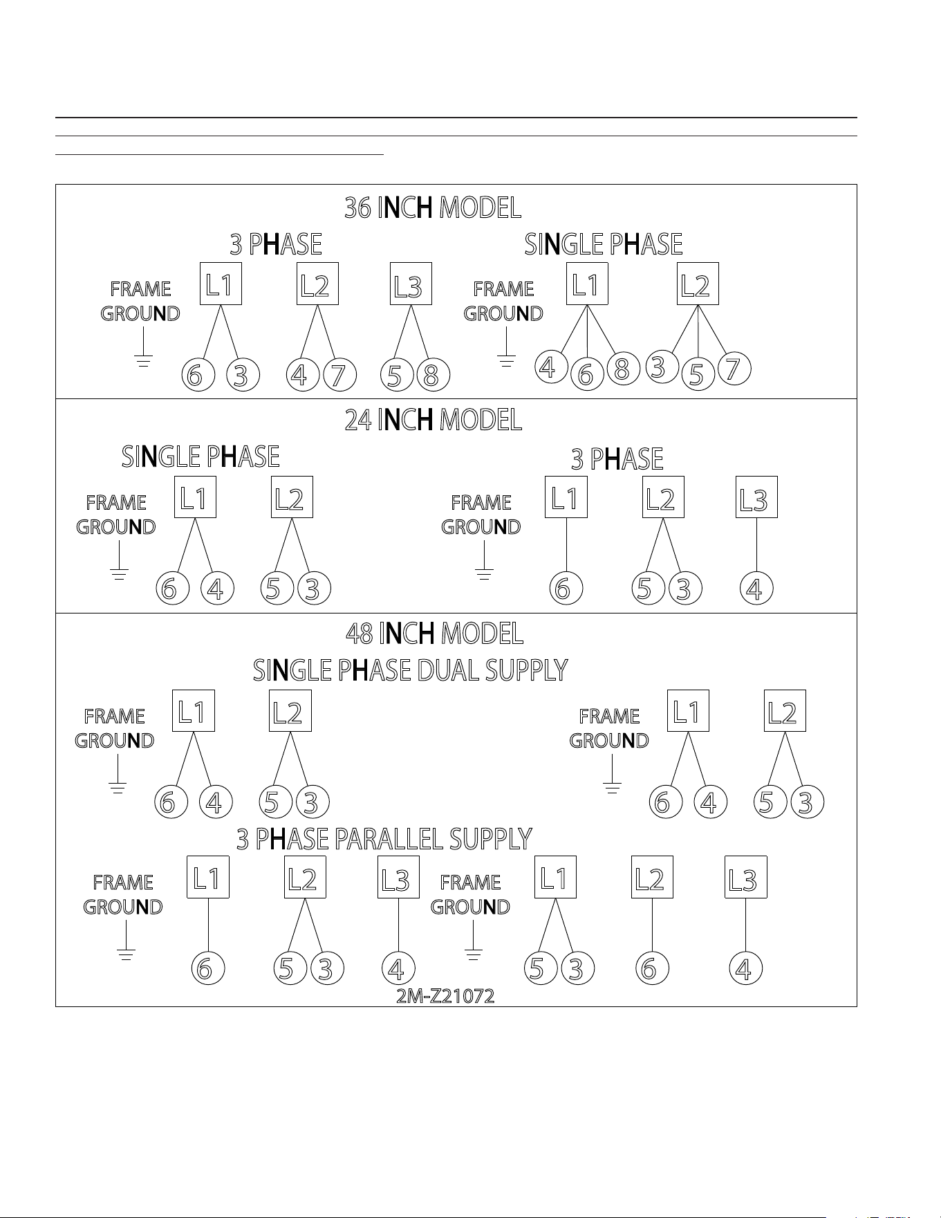
Models may be wired for operation in the eld for either 1-phase or 3-phase power supplies by making
line connections at the junction box located at the rear of the unit as described on the phase diagram.
EG-36S and EG-48S models are recommended to be wired for 3-phase operation. EG-48S models are
supplied with two junction boxes and can be wire to two (2) 8 kW lines or a single 16 kW line.
CONNECT/PLUG UNIT INTO DEDICATED AC LINE WITH APPROPRIATE AMPERAGE/VOLTAGE AS
SPECIFIED ON THE NAMEPLATE OF THE UNIT.
DO NOT IMMERSE OR LET THE UNIT STAND IN WATER.
DO NOT HOSE DOWN THE UNIT OR THE TABLE/COUNTER IF THE UNIT IS ON THE TABLE/COUNTER.
KEEP AWAY FROM RUNNING WATER.
2M-Z23810: APW Wyott EG Series Electric Griddles
3
PHASE DIAGRAM
POWER MUST BE REMOVED FROM THE UNIT BEFORE ATTEMPTING REPAIR OR SERVICE. MAKE CERTAIN TO
CHECK ALL CONNECTIONS THOROUGHLY BEFORE RESTORING POWER TO THE UNIT. THE INFORMATION BELOW
IS REFERENCED FROM DIAGRAM 2M-Z21072.
5
3
6
4
L1
L2
L3
7
8
36 INCH MODEL
3 PHASE SINGLE PHASE
SINGLE PHASE
L2
L1
5
6
3
L3
4
3 PHASE
L2
5
L1
3
4
6
24 INCH MODEL
FRAME
GROUND
FRAME
GROUND
FRAME
GROUND
3 PHASE PARALLEL SUPPLY
3
48 INCH MODEL
4
SINGLE PHASE DUAL SUPPLY
FRAME
GROUND
6
L1
FRAME
GROUND
3
5
L2
6
5
L1
L2
2M-Z21072
4
L3
4
FRAME
GROUND
6
L1
3
5
L2
3
FRAME
GROUND
6
5
L1
L2
4
L3
3
L1
L2
7
FRAME
GROUND
5
4
8
6

2M-Z23810: APW Wyott EG Series Electric Griddles
4
DAILY OPERATION
GRIDDLE CARE
It takes very little time and eort to keep the griddle
attractive and performing at top eciency. If grease
is permitted to accumulate, it forms a viscous residue
and then carbonizes, making it extremely dicult
to remove. To prevent this condition, the following
suggestions for cleanliness should be followed.
i. After each use, scrape the griddle with a scraper
or exible spatula to remove excess grease and
food and maneuver it into the grease chute. If
there is an accumulation of burned on grease
and/or food, the griddle should be thoroughly
scoured and reseasoned. Use pumice or griddle
stone while the griddle is warm. Do not use
steel wool because of the danger of steel slivers
getting into the food
ii. Daily use a clean cloth and a good non-abrasive
cleaner to clean the stainless steel body of the
griddle is recommended. Wipe the polished
front with a soft cloth so not to scratch the nish.
iii. At least once a day, remove the grease drawer
and wash it using the same process as an
ordinary cooking utensil. The drawer is removed
by pulling forward until it is released from its
track.
SEASONING THE GRIDDLE HEATING SURFACE
Clean the griddle surface thoroughly. After the
griddle has been thoroughly cleaned, it should
be seasoned to prevent food from sticking. Before
using and after each thorough scouring, season the
griddle heating surface in the following manner.
i. Turn the temperature control dials to 350°F
(177°C).
ii. Using a clean cloth, not a spatula, spread a thin
lm of cooking oil over the griddle cooking
surface. This lm should remain on the hot
griddle surface for half an hour.
iii. Remove the excess oil and wipe clean.
iv. Apply another lm of cooking oil over the hot
cooking area for another half hour and again
remove excess oil and wipe clean. The griddle
surface should now be ready for use
TEMPERATURE CONTROL
The temperature controls are combination “ON/OFF”
switches and thermostats. Turning the dial knob
automatically maintains the selected heat range.
There is one thermostat for every twelve [12] inch
(305 mm) wide section that operate independently.
COOKING
Set the thermostat dial knob at the desired
temperature. After a short pre-heating period, the
thermostat will automatically maintain the selected
temperature.
IDLING
During idle periods, to save on operating costs,
lower the temperature setting of the thermostat to
about 250°F (121°C). It is not necessary to maintain
cooking temperature during idle periods, as the
griddle can quickly be reheated to the desired
temperature.
SIGNAL LIGHTS
Each thermostat has its own signal light which
indicates when the unit’s control knob is not in the
o position.
GREASE PAN
The grease pan on the front is hot and contains hot
grease. Take care when removing and emptying the
tray. The tray should be checked and emptied on a
regular basis.
2M-Z23810: APW Wyott EG Series Electric Griddles
5
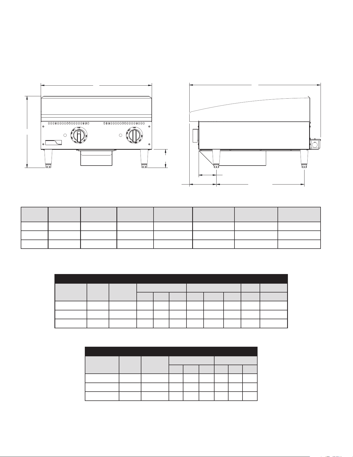
SPECIFICATIONS
EG-24S shown
A
19.0 [48.3]
B
5.8 [14.8]
3.8 [9.7]
C
4.0 [10.0]
Model
No.
(A) Width
Inches (cm)
(B) Depth
Inches (cm)
(C) Height
Inches (cm)
(D) Leg Width
Inches (cm)
Plate Depth
Inches (mm)
Installed Weight
lbs. (kg)
Shipping Weight
lbs. (kg)
EG-24S 24 (61.0) 28-1/2 (72.1) 15-1/2 (39.4) 19 (48.3) 20.5 (128.3 cm) 165 (74.8) 175 (79.4)
EG-36S 36 (91.4) 28-1/2 (72.1) 15-1/2 (39.4) 32-3/4 (83.2) 20.5 (128.3 cm) 247 (112.0) 262 (118.9)
EG-48S 48 (121.9) 28-1/2 (72.1) 15-1/2 (39.4) 44-3/4 (113.7) 20.5 (128.3 cm) 330 (149.7) 350 (158.9)
3 PHASE LOADING KW PER PHASE
MODEL 208V 240V
208V 50/60 HZ 240V 50/60 HZ
X-Y Y-Z X-Z X-Y Y-Z X-Z
EG-24S 6,008 8,000 3 3 - 4 4 -
EG-36S 9,012 12,000 3 3 3 4 4 4
EG-48S 12,016 16,000 3 3 6 4 4 8
NOMINAL AMPS PER LINE WIRE
MODEL 208V 240V
208V 3PH 240V 3PH 208V 240V
X Y Z X Y Z 1 PH 1 PH
EG-24S 6,008 8,000 14.4 25 14.4 16.7 28.9 16.7 28.9 33.3
EG-36S 9,012 12,000 25 25 25 28.9 28.9 28.9 43.3 50.0
EG-48S 12,016 16,000 38.2 25 38.2 44.2 28.9 44.2 57.8 66.7
2M-Z23810: APW Wyott EG Series Electric Griddles
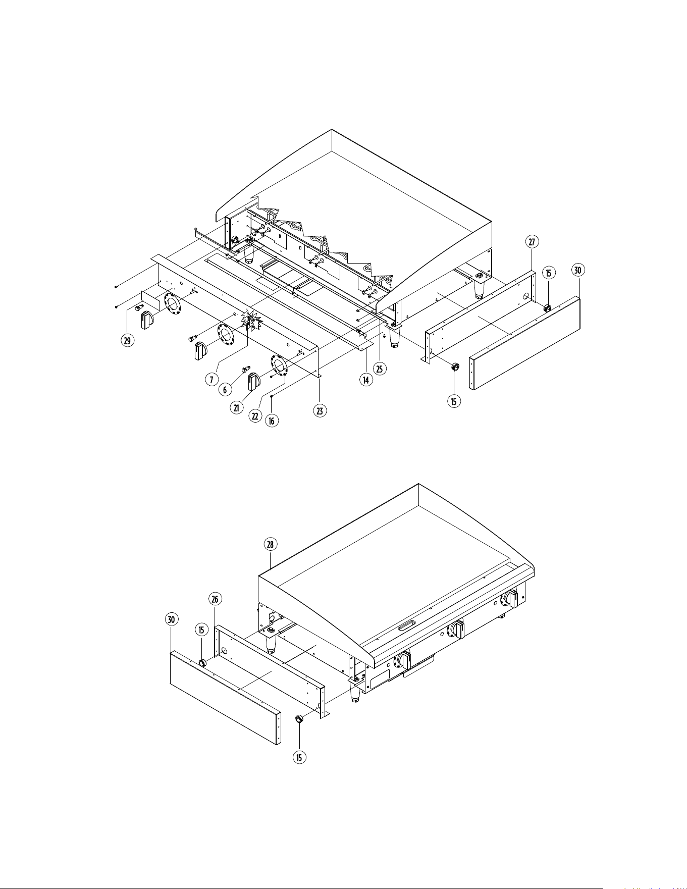
6
FRONT-PANEL AND CONTROLS
RIGHT SIDE-PANELS
EG-36S shown
LEFT SIDE-PANELS
EG-36S shown
2M-Z23810: APW Wyott EG Series Electric Griddles
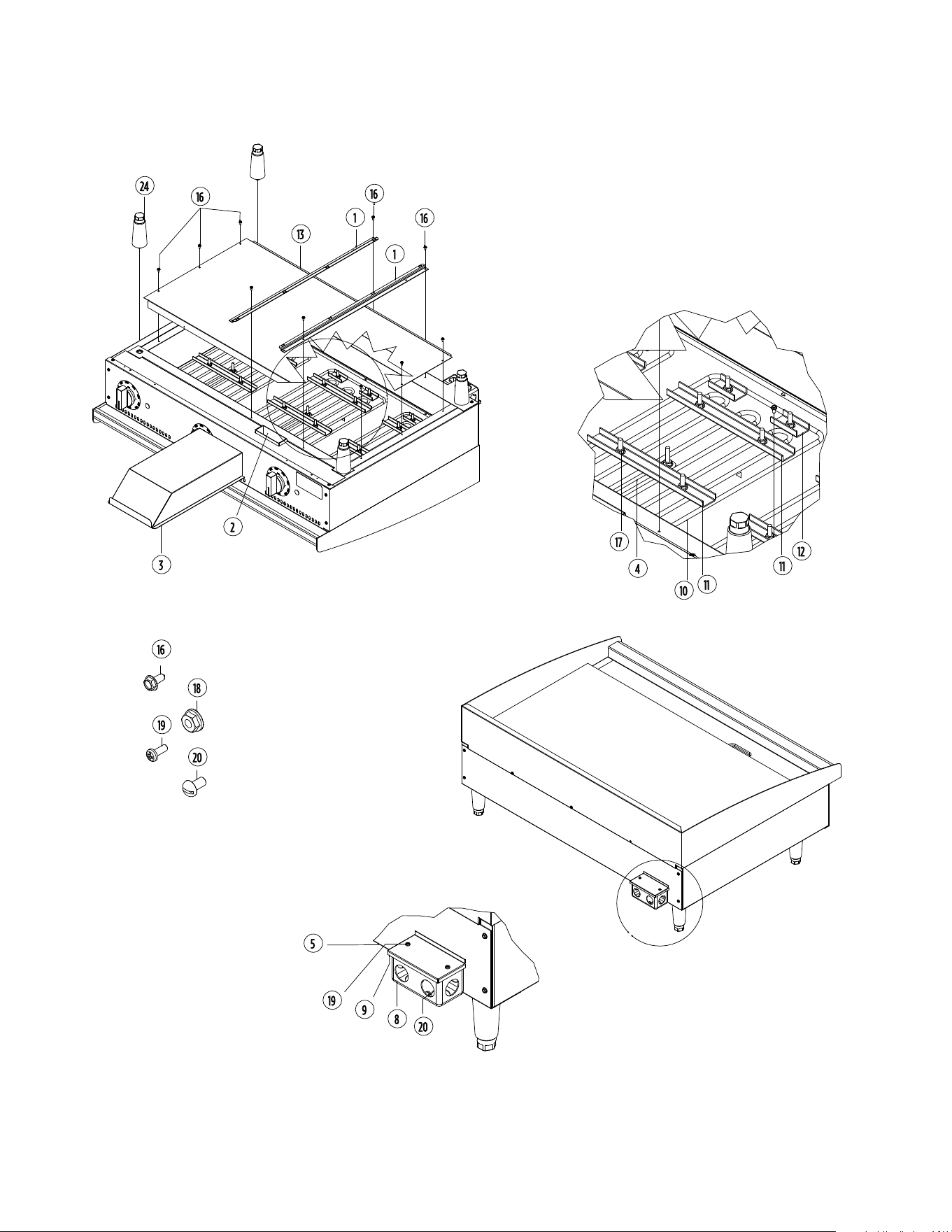
7
BOTTOM
EG-36S shown
HEATING ELEMENT
HARDWARE
EG-36S shown
REAR-ELECTRICAL BOX
EG-36S shown
POWER JUNCTION BOX

2M-Z23810: APW Wyott EG Series Electric Griddles
8
PARTS LIST
NOTE: Side references are from the operator’s point-of-view – from the front of the unit. Items labeled “NS”
are non-serviceable. Items labeled “NP” are not pictured.
P/N MODEL PART NUMBER QTY DESCRIPTION PAGE NO
1 ALL G3-Z6036 2 DRAWER SLIDE 7
2 ALL G3-624304 1 GREASE CHUTE 7
3 ALL G3-Y7046 1 GREASE DRAWER 7
4
EG-24S
G3-GD0036
2
PROBE TUBE ASSEMBLY 7EG-36S 3
EG-48S 4
5
EG-24S G3-Z5952 1 PANEL, REAR 24 INCH
7EG-36S G3-Z5954 1 PANEL, REAR 36 INCH
EG-48S G3-Z5956 1 PANEL, REAR 48 INCH
6
EG-24S
2J-Y6690
2
INDICATOR LIGHT, RED 6EG-36S 3
EG-48S 4
7
EG-24S
2T-Z5958
2
THERMOSTAT 6EG-36S 3
EG-48S 4
8
EG-24S
2E-Y7327
1
HANDY BOX 7EG-36S 1
EG-48S 2
9
EG-24S
G3-Y7788
1
COVER, HANDY BOX 7EG-36S 1
EG-48S 2
10
EG-24S
2N-Z5948
2
HEATING ELEMENT 7EG-36S 3
EG-48S 4
11
EG-24S
G3-Z5972
6
ELEMENT CLAMP, LONG 7EG-36S 9
EG-48S 12
12
EG-24S
G3-Z5973
4
ELEMENT CLAMP, SHORT 7EG-36S 6
EG-48S 8
13
EG-24S G3-Z5994
1
PANEL, BOTTOM 24 INCH
7EG-36S G3-Z5995 PANEL, BOTTOM 36 INCH
EG-48S G3-Z5996 PANEL, BOTTOM 48 INCH
14
EG-24S G3-Z5998
1
PANEL, FRONT BOTTOM 24 INCH
6EG-36S G3-Z5999 PANEL, FRONT BOTTOM 36 INCH
EG-48S G3-Z6001 PANEL, FRONT BOTTOM 48 INCH
15
EG-24S
2K-Z6183
3
BUSHING 6EG-36S 3
EG-48S 6
IMPORTANT: WHEN ORDERING, SPECIFY VOLTAGE OR TYPE GAS DESIRED
INCLUDE MODEL AND SERIAL NUMBER PAGE 1 OF 2
Some items are included for illustrative purposes only and in certain instances may not be available.

2M-Z23810: APW Wyott EG Series Electric Griddles
9
P/N MODEL PART NUMBER QTY DESCRIPTION PAGE NO
16
EG-24S 2E-Z5970 1 WIRING SET, 24 INCH
NPEG-36S 2E-Z5971 1 WIRING SET, 36 INCH
EG-48S 2E-Z5970 2 WIRING SET, 48 INCH
17
EG-24S
2C-6517
18
1/4-20 FLANGED HEX NUT 7EG-36S 27
EG-48S 34
18 ALL 2C-Z2893 4 #10-24 NUT 7
19
EG-24S
2C-1488
2
#6-32 X 0.375 INCH MACHINE SCREW 7EG-36S 2
EG-48S 4
20
EG-24S
2C-1512
2
#10-24 X 0.375 INCH MACHINE SCREW 7EG-36S 2
EG-48S 4
21
EG-24S
2R-Z13016
2
KNOB, T-STAT ELEC. 6EG-36S 2
EG-48S 4
22
EG-24S
RM-Z15451
2
LABEL, APW Wyott ELECTRIC KNOB 6EG-36S 3
EG-48S 4
23
EG-24S G3-Z15708
1
PANEL, FRONT 24 INCH
6EG-36S G3-Z15709 PANEL, FRONT 36 INCH
EG-48S G3-Z15796 PANEL, FRONT 48 INCH
24 ALL 2A-Z5942 4 4 INCH LEG 7
25
EG-24S G3-Z5915
1
CENTER WALL ASSEMBLY, 24 INCH
6-NSEG-36S G3-Z5925 CENTER WALL ASSEMBLY, 36 INCH
EG-48S G3-Z5935 CENTER WALL ASSEMBLY, 48 INCH
26 ALL G3-624302 1 LINER ASSEMBLY, LEFT 6
27 ALL G3-624303 1 LINER ASSEMBLY, RIGHT 6
28
EG-24S G4-TC0098
1
TOP WELDMENT, 24 INCH ELECTRIC
6EG-36S G4-TC0104 TOP WELDMENT, 36 INCH ELECTRIC
EG-48S G4-TC0107 TOP WELDMENT, 48 INCH ELECTRIC
29 ALL 2M-8830100 1 APW WYOTT BADGE 6
30 ALL G3-Z5945 2 PANEL, SIDE 6
31
EG-24S
G3-Z5947
2
COVER, ELECTRIC NPEG-36S 3
EG-48S 4
32
EG-24S
2C-8833
43
#8-18 X 0.5 INCH SCREW NPEG-36S 51
EG-48S 56
33 ALL 2C-Z6035 2 1/2-13 X 3 INCH BOLT NP
PARTS LIST
IMPORTANT: WHEN ORDERING, SPECIFY VOLTAGE OR TYPE GAS DESIRED
INCLUDE MODEL AND SERIAL NUMBER PAGE 2 OF 2
Some items are included for illustrative purposes only and in certain instances may not be available.

PAGE INTENTIONALLY LEFT BLANK

APW Wyott • www.apwwyott.com
265 Hobson St. • Smithville, TN 37166
Telephone: (800) 527-2100
Printed in the U.S.A. • 2M-Z23810 • Rev A (12-21)
Specifications are subject to change without notice.
is a registered trademark of APW Wyott®, A Middleby Company. All rights reserved.