CUSTOM MANUFACTURED FOR RADIO SHACK
A DIVISION OF TANDY CORPORATION
PLEASE READ BEFORE
USING THIS EQUIPMENT
Cat. No.
14-1348
OWNER'S
‘gig' C
InD© Di@©h
D:L
r
%)V
HEDk@
n@6M©@ff
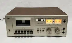
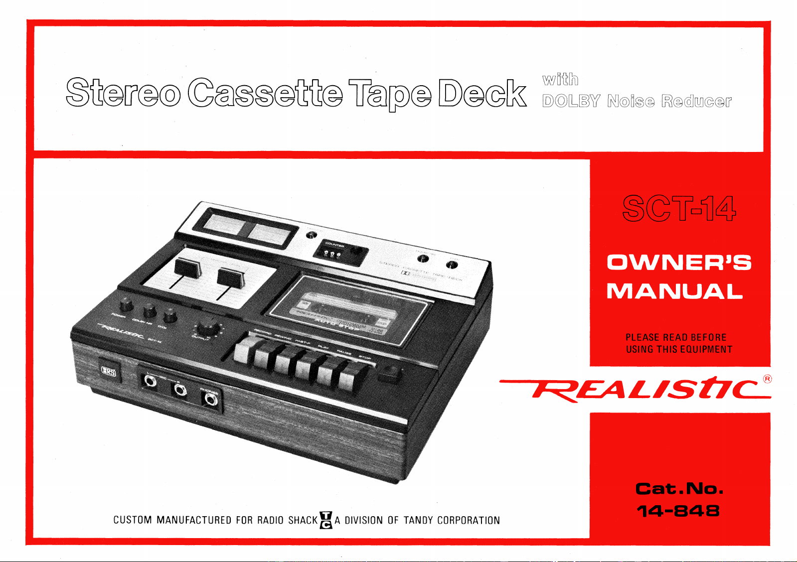
Your
REALISTIC SCT-14
is a high-quality Stereo Cassette Tape
Deck. It incorporates the latest technological advances, including, the
DOLBY* Noise Reduction circuitry (under license from Dolby
Laboratories Inc.). Use your SCT-14 to make professional quality
recordings right in your home—with results that will challenge even
those made on high-quality reel-to-reel recorders.
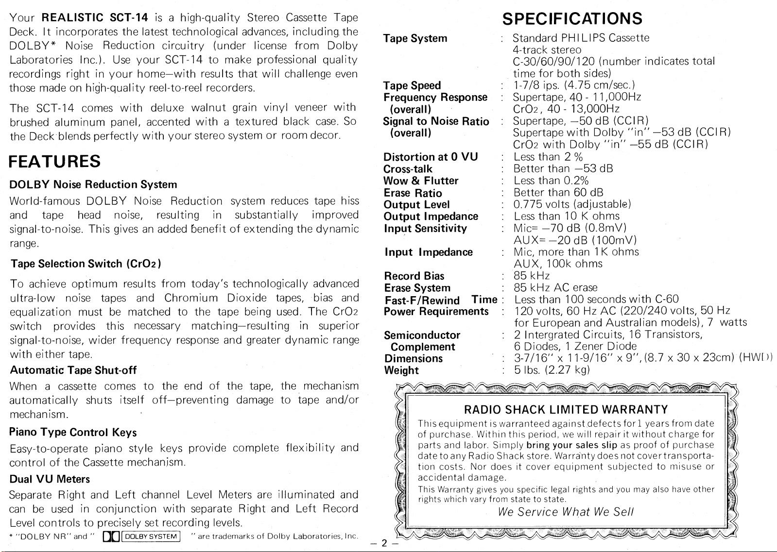
The SCT-14 comes with deluxe walnut grain vinyl veneer with
brushed aluminum panel, accented with a textured black case. So
the Deck blends perfectly with your stereo system or room decor.
FEATURES
DOLBY Noise Reduction System
World-famous DOLBY Noise Reduction system reduces tape hiss
and tape head noise, resulting in substantially improved
signal-to-noise. This gives an added benefit of extending the dynamic
range
Tape Selection Switch (Cr02)
To achieve optimum results from today's technologically advanced
ultra-low noise tapes and Chromium Dioxide tapes, bias and
equalization must be matched to the tape being used. The Cr02
switch provides this necessary matching—resulting in superior
signal-to-noise, wider frequency response and greater dynamic range
with either tape.
Automatic Tape Shut-off
When a cassette comes to the end of the tape, the mechanism
automatically shuts itself off—preventing damage to tape and/or
mechanism.
Piano Type Control Keys
Easy-to-operate piano style keys provide complete flexibility and
control of the Cassette mechanism.
Dual VU Meters
Separate Right and Left channel Level Meters are illuminated and
can be used in conjunction with separate Right and Left Record
Level controls to precisely set recording levels.
* "DOLBY N R" and " DO
DOLBY SYSTEM 1
- are trademarks of Dolby Laboratories, Inc.
SPECIFICATIONS
Standard PHI LIPS Cassette
4-track stereo
C-30/60/90/120 (number indicates total
time for both sides)
1-7/8 ips. (4.75 cm/sec.)
Supertape, 40 - 11,000Hz
Cr02, 40 - 13,000Hz
Supertape, —50 dB (CCI R )
Supertape with Dolby "in" —53 dB (CCI R)
Cr02 with Dolby "in" —55 dB (CCI R)
Less than 2%
Better than —53 dB
Less than 0.2%
Better than 60 dB
0.775 volts (adjustable)
Less than 10 K ohms
Mic= —70 dB (0.8mV)
AUX= —20 dB (100mV)
Mic, more than 1K ohms
AUX, 100k ohms
85 kHz
85 kHz AC erase
Less than 100 seconds with C-60
120 volts, 60 Hz AC (220/240 volts, 50 Hz
for European and Australian models), 7 watts
2 I ntergrated Circuits, 16 Transistors,
6 Diodes, 1 Zener Diode
3-7/16" x 11-9/16" x 9", (8.7 x 30 x 23cm) (HW[ ))
5 lbs. (2.27 kg)
•
Nr\``
RADIO SHACK LIMITED WARRANTY
This equipment is warranteed against defects for 1 years from date
of purchase. Within this period, we will repair it without charge for
parts and labor. Simply
bring your sales slip
as proof of purchase
date to any Radio Shack store. Warranty does not cover transporta-
tion costs. Nor does it cover equipment subjected to misuse or
accidental damage.
This Warranty gives you specific legal rights and you may also have other
rights which vary from state to state.
We Service What We Sell
,///,
— 2 —
Tape System
Tape Speed
Frequency Response
(overall)
Signal to Noise Ratio
(overall)
Distortion at 0 VU
Cross-talk
Wow & Flutter
Erase Ratio
Output Level
Output Impedance
Input
y
Sensitivity
Input Impedance
Record Bias
Erase System
Fast-F/Rewind Time
Power Requirements :
Semiconductor
Complement
Dimensions
Weight
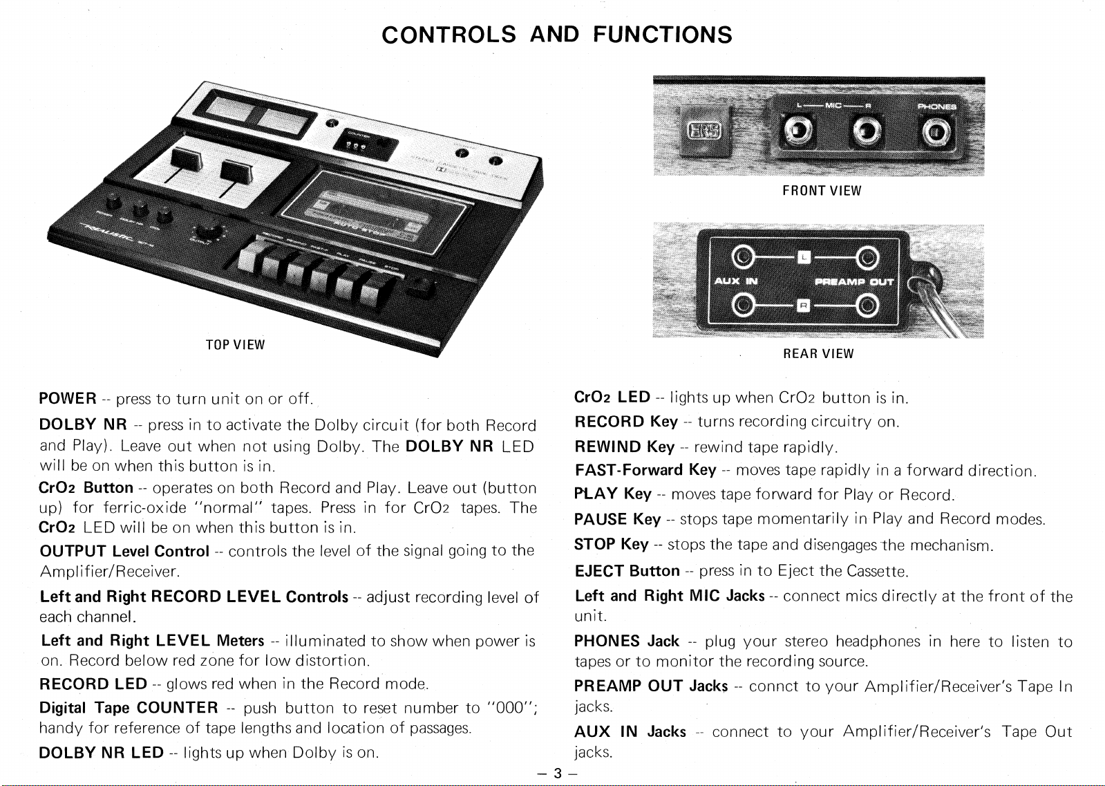
FRONT VIEW
REAR VIEW
CONTROLS AND FUNCTIONS
POWER --
press to turn unit on or off.
DOLBY NR --
press in to activate the Dolby circuit (for both Record
and Play). Leave out when not using Dolby. The
DOLBY NR
LED
will be on when this button is in.
Cr02 Button --
operates on both Record and Play. Leave out (button
up) for ferric-oxide "normal" tapes. Press in for Cr02 tapes. The
Cr02
LED will be on when this button is in.
OUTPUT Level Control --
controls the level of the signal going to the
Amplifier/Receiver.
Left and Right RECORD LEVEL Controls --
adjust recording level of
each channel.
Left and Right LEVEL Meters --
illuminated to show when power is
on. Record below red zone for low distortion.
RECORD LED --
glows red when in the Record mode.
Digital Tape COUNTER —
push button to reset number to "000";
handy for reference of tape lengths and location of passages.
DOLBY NR LED --
lights up when Dolby is on.
Cr02 LED --
lights up when Cr02 button is in.
RECORD Key --
turns recording circuitry on.
REWIND Key --
rewind tape rapidly.
FAST-Forward Key --
moves tape rapidly in a forward direction.
PLAY Key --
moves tape forward for Play or Record.
PAUSE Key --
stops tape momentarily in Play and Record modes.
STOP Key --
stops the tape and disengages the mechanism.
EJECT Button --
press in to Eject the Cassette.
Left and Right MIC Jacks --
connect mics directly at the front of the
unit.
PHONES Jack --
plug your stereo headphones in here to listen to
tapes or to monitor the recording source.
PREAMP OUT Jacks
connct to your Amplifier/Receiver's Tape In
jacks.
AUX IN Jacks
connect to your Amplifier/Receiver's Tape Out
jacks.
OPERATION
TURNING UNIT ON:
The SCT-14 offers the convenience of a separate on/off control. To
turn the unit on, press
POWER
in to turn "on".
To turn the unit off, simply press
POWER
again.
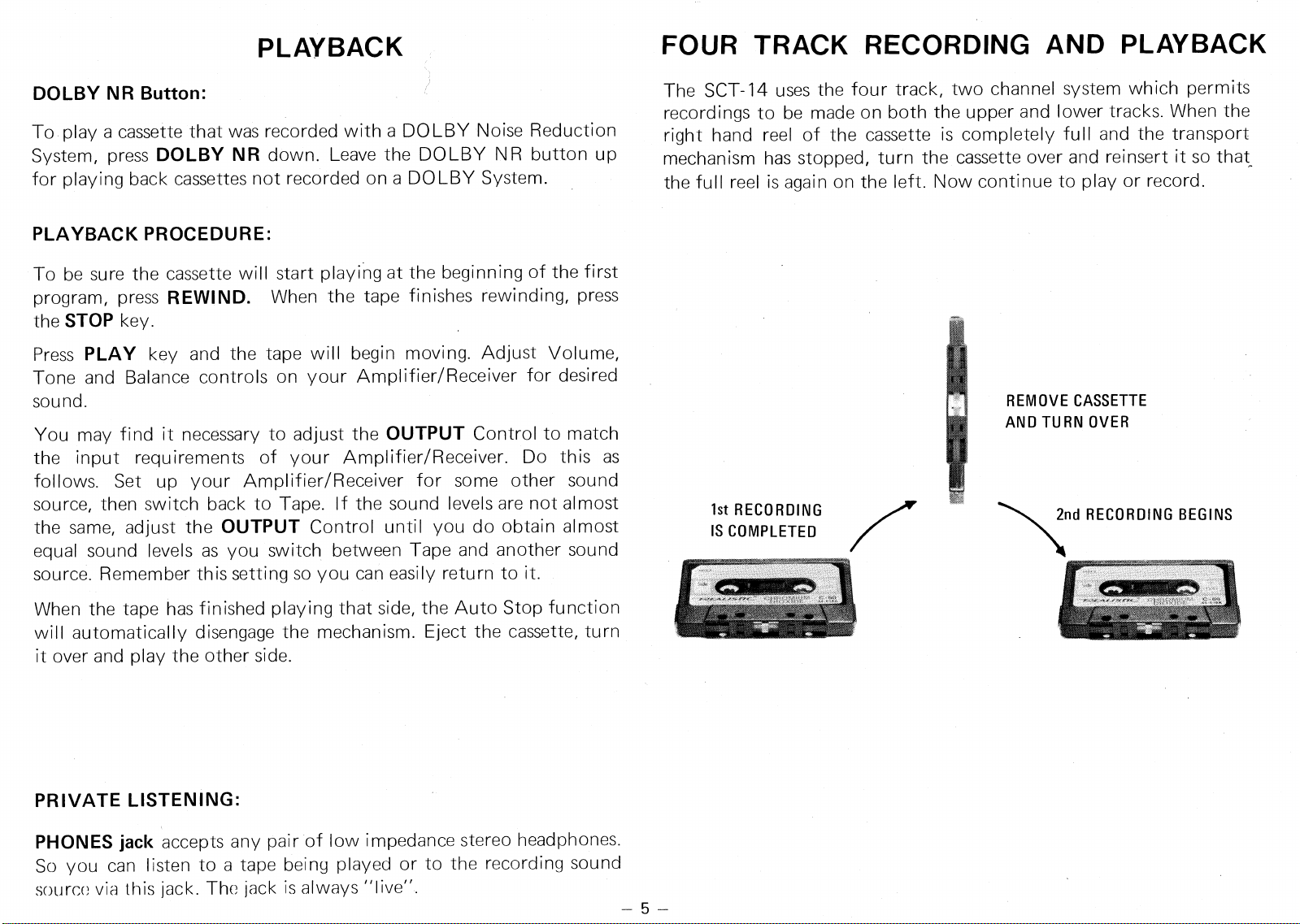
INSERTING A CASSETTE:
If all tape function keys are not in the "up" position, press the
STOP
key. To open the Cassette Lid, press the
EJECT
button. Insert a
cassette and be sure that it is properly seated and that the full reel of
tape is on the left. Close the Cassette Lid. To remove a cassette, the
tape transport mechanism must be stopped (either automatically or
manually by pressing the
STOP
key). Press the
EJECT
button and
the Cassette Lid will open and the cassette will pop out.
FULL REEL ON LEFT
REMOVING A CASSETTE
1.
Press
STOP
key.
2.
Press
EJECT;
the cover will open and the cassette will pop up.
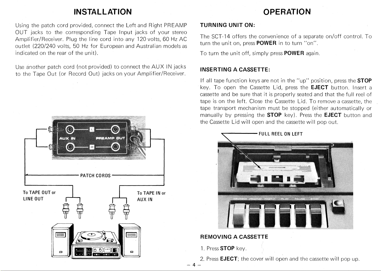
To TAPE OUT or
LINE OUT
To TAPE IN or
AUX IN
"Inic4;iz
04W,,
VIANWIRML,
NSW"
OM'
PATCH CORDS
INSTALLATION
Using the patch cord provided, connect the Left and Right PREAMP
OUT jacks to the corresponding Tape Input jacks of your stereo
Amplifier/Receiver. Plug the line cord into any 120 volts, 60 Hz AC
outlet (220/240 volts, 50 Hz for European and Australian models as
indicated on the rear of the unit).
Use another patch cord (not provided) to connect the AUX IN jacks
to the Tape Out (or Record Out) jacks on your Amplifier/Receiver.
4—
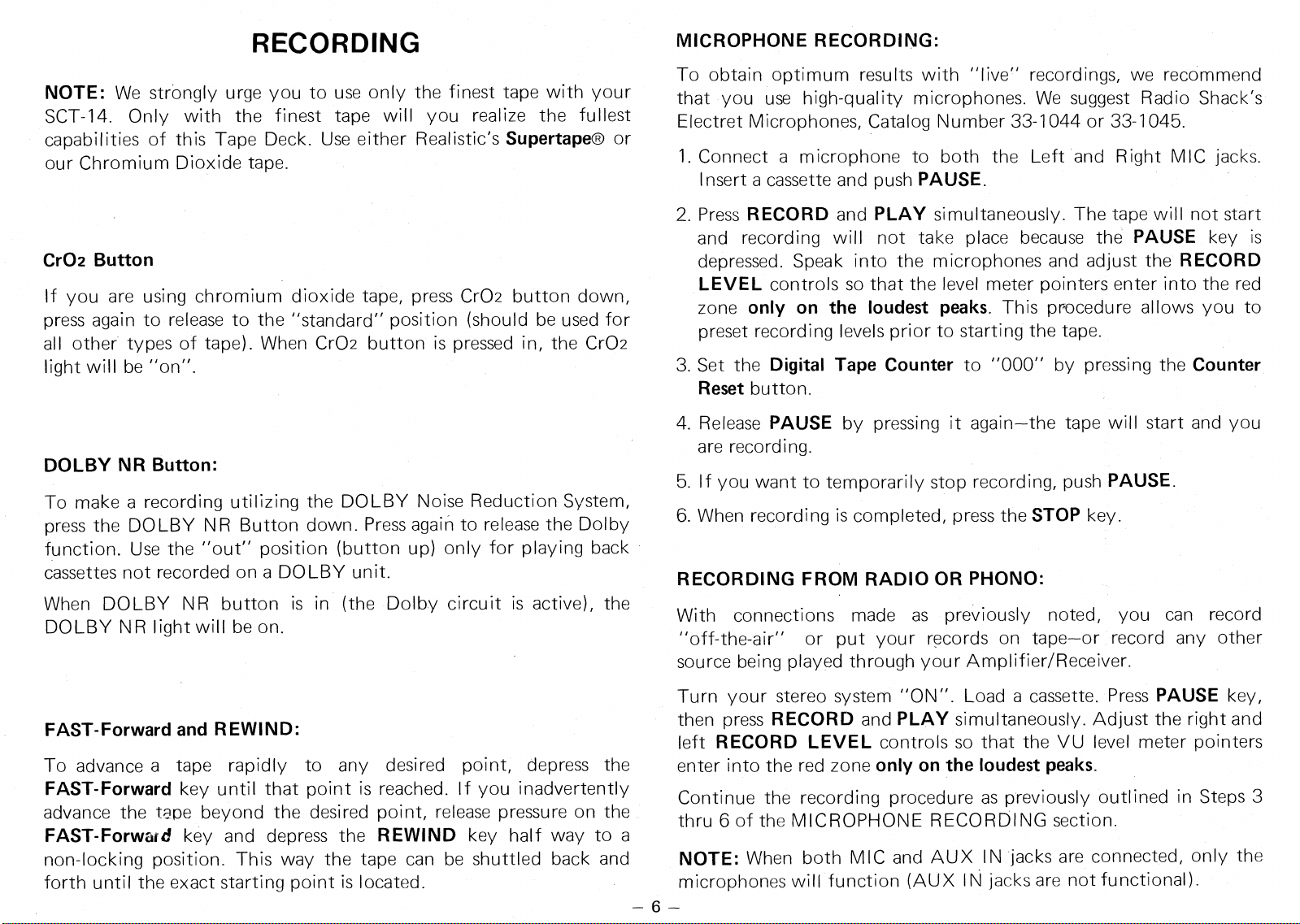
2nd RECORDING BEGINS
1st RECORDING
IS COMPLETED
REMOVE CASSETTE
AND TURN OVER
PLAYBACK
DOLBY NR Button:
To play a cassette that was recorded with a DOLBY Noise Reduction
System, press
DOLBY NR
down. Leave the DOLBY NR button up
for playing back cassettes not recorded on a DOLBY System.
PLAYBACK PROCEDURE:
To be sure the cassette will start playing at the beginning of the first
program, press
REWIND.
When the tape finishes rewinding, press
the
STOP
key.
Press
PLAY
key and the tape will begin moving. Adjust Volume,
Tone and Balance controls on your Amplifier/Receiver for desired
sound.
You may find it necessary to adjust the
OUTPUT
Control to match
the input requirements of your Amplifier/Receiver. Do this as
follows. Set up your Amplifier/Receiver for some other sound
source, then switch back to Tape. If the sound levels are not almost
the same, adjust the
OUTPUT
Control until you do obtain almost
equal sound levels as you switch between Tape and another sound
source. Remember this setting so you can easily return to it.
When the tape has finished playing that side, the Auto Stop function
will automatically disengage the mechanism. Eject the cassette, turn
it over and play the other side.
PRIVATE LISTENING:
PHONES jack
accepts any pair of low impedance stereo headphones.
So you can listen to a tape being played or to the recording sound
source via this jack. The jack is always "live"
FOUR TRACK RECORDING AND PLAYBACK
The SCT-14 uses the four track, two channel system which permits
recordings to be made on both the upper and lower tracks. When the
right hand reel of the cassette is completely full and the transport
mechanism has stopped, turn the cassette over and reinsert it so that
the full reel is again on the left. Now continue to play or record.
5
RECORDING
NOTE:
We strongly urge you to use only the finest tape with your
SCT-14. Only with the finest tape will you realize the fullest
capabilities of this Tape Deck. Use either Realistic's
Supertape®
or
our Chromium Dioxide tape.
Cr02 Button
If you are using chromium dioxide tape, press Cr02 button down,
press again to release to the "standard" position (should be used for
all other types of tape). When Cr02 button is pressed in, the Cr02
light will be "on".
DOLBY NR Button:
To make a recording utilizing the DOLBY Noise Reduction System,
press the DOLBY NR Button down. Press again to release the Dolby
function. Use the "out" position (button up) only for playing back
cassettes not recorded on a DOLBY unit.
When DOLBY NR button is in (the Dolby circuit is active), the
DOLBY NR light will be on.
FAST-Forward and REWIND:
To advance a tape rapidly to any desired point, depress the
FAST-Forward
key until that point is reached. If you inadvertently
advance the tape beyond the desired point, release pressure on the
FAST-Forwaid
key and depress the
REWIND
key half way to a
non-locking position. This way the tape can be shuttled back and
forth until the exact starting point is located.
MICROPHONE RECORDING:
To obtain optimum results with "live" recordings, we recommend
that you use high-quality microphones. We suggest Radio Shack's
Electret Microphones, Catalog Number 33-1044 or 33-1045.
1.
Connect a microphone to both the Left and Right MIC jacks.
Insert a cassette and push
PAUSE.
2.
Press
RECORD
and
PLAY
simultaneously. The tape will not start
and recording will not take place because the
PAUSE
key is
depressed. Speak into the microphones and adjust the
RECORD
LEVEL
controls so that the level meter pointers enter into the red
zone
only on the loudest peaks.
This procedure allows you to
preset recording levels prior to starting the tape.
3.
Set the
Digital Tape Counter
to "000" by pressing the
Counter
Reset
button.
4.
Release
PAUSE
by pressing it again—the tape will start and you
are recording.
5.
If you want to temporarily stop recording, push
PAUSE.
6.
When recording is completed, press the
STOP
key.
RECORDING FROM RADIO OR PHONO:
With connections made as previously noted, you can record
"off-the-air" or put your records on tape—or record any other
source being played through your Amplifier/Receiver.
Turn your stereo system "ON". Load a cassette. Press
PAUSE
key,
then press
RECORD
and
PLAY
simultaneously. Adjust the right and
left
RECORD LEVEL
controls so that the VU level meter pointers
enter into the red zone
only on the loudest peaks.
Continue the recording procedure as previously outlined in Steps 3
thru 6 of the MICROPHONE RECORDING section.
NOTE:
When both MIC and AUX IN jacks are connected, only the
microphones will function (AUX IN jacks are not functional).
— 6 —
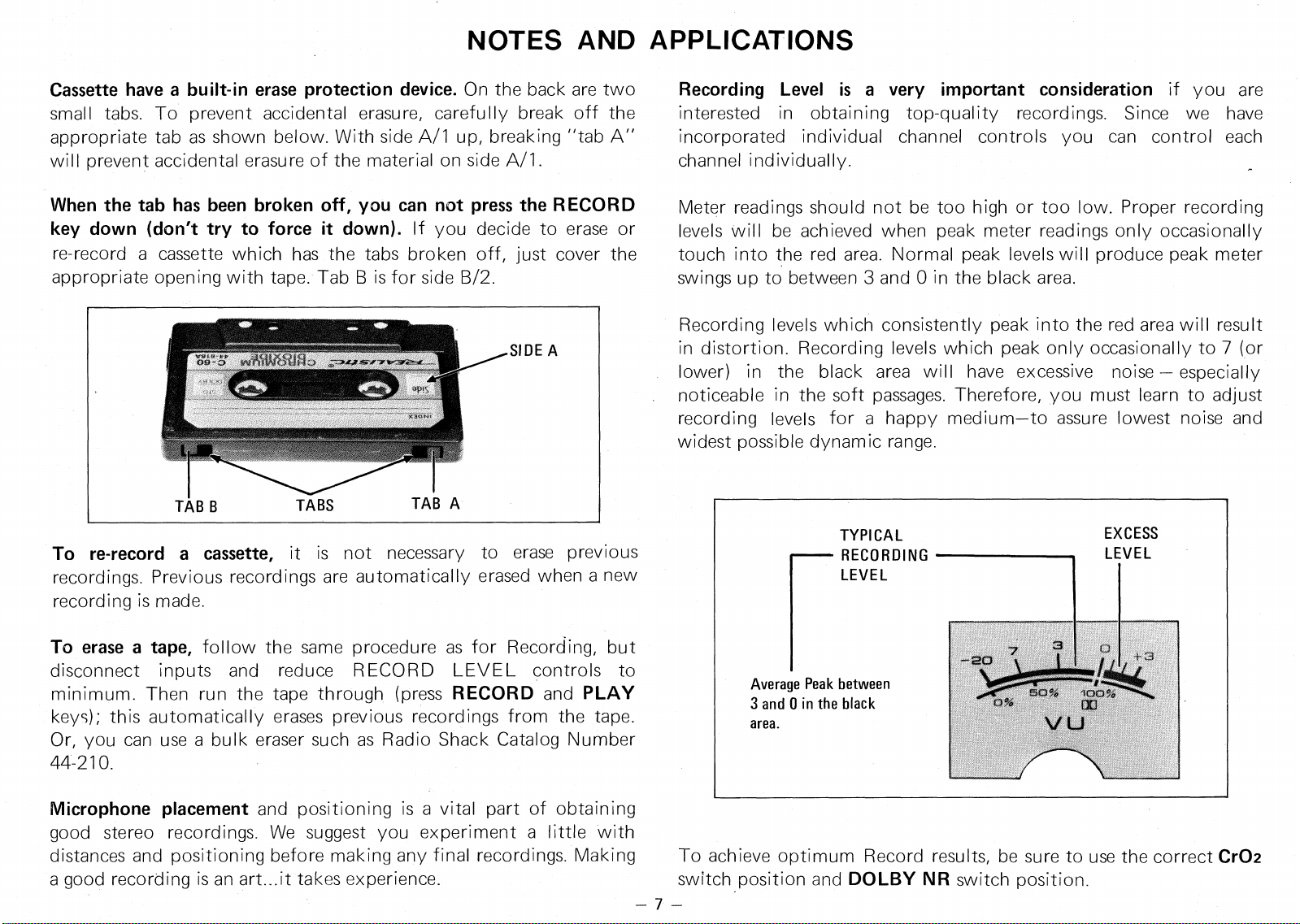
Average Peak between
3 and 0 in the black
area.
NOTES AND APPLICATIONS
Cassette have a built-in erase protection device.
On the back are two
small tabs. To prevent accidental erasure, carefully break off the
appropriate tab as shown below. With side A/1 up, breaking "tab A"
will prevent accidental erasure of the material on side A/1.
When the tab has been broken off, you can not press the RECORD
key down (don't try to force it down).
If you decide to erase or
re-record a cassette which has the tabs broken off, just cover the
appropriate opening with tape. Tab B is for side B/2.
To re-record a cassette,
it is not necessary to erase previous
recordings. Previous recordings are automatically erased when a new
recording is made.
To erase a tape,
follow the same procedure as for Recording, but
disconnect inputs and reduce RECORD LEVEL controls to
minimum. Then run the tape through (press
RECORD
and
PLAY
keys); this automatically erases previous recordings from the tape.
Or, you can use a bulk eraser such as Radio Shack Catalog Number
44-210.
Recording Level is a very important consideration
if you are
interested in obtaining top-quality recordings. Since we have
incorporated individual channel controls you can control each
channel individually.
Meter readings should not be too high or too low. Proper recording
levels will be achieved when peak meter readings only occasionally
touch into the red area. Normal peak levels will produce peak meter
swings up to between 3 and 0 in the black area.
Recording levels which consistently peak into the red area will result
in distortion. Recording levels which peak only occasionally to 7 (or
lower) in the black area will have excessive noise — especially
noticeable in the soft passages. Therefore, you must learn to adjust
recording levels for a happy medium—to assure lowest noise and
widest possible dynamic range.
Microphone placement
and positioning is a vital part of obtaining
good stereo recordings. We suggest you experiment a little with
distances and positioning before making any final recordings. Making
To achieve optimum Record results, be sure to use the correct
Cr02
a good recording is an art...it takes experience.
switch position and
DOLBY NR
switch position.
— 7 —
Demagnetize the tape heads and clean the tape handling parts
periodically...this
will insure maximum frequency response and
lowest noise. After a few hours of recording or playing, dust lint and
tape oxide will begin to build up on the tape heads and guides; this
affects record and play quality. To achieve the professional quality
this system is capable of, such dust, lint and oxide must be cleand
off. Also, the heads tend to retain redidual magnetism after some
hours of use.. .this introduces noise on both record and playback. To
clean, we recommend using Radio Shack Catalog Number 44-1160
Cassette Head Cleaner or use cleaning sticks (44-1093) and Recorder
Cleaner (44-1010). To remove residual magnetism, use a Tape Head
Demagnetizer such as 44-215 or 44-211. Or, easier still, you can
clean and demagnetize by one simple play-through of our Cassette
Demagnetizer and Cleaner 44-631.
Choice of tape is vital to good recordings.
For most voice recordings
(dictation, notes, lectures, etc.) either the
CONCERTAPE
or
REALISTIC
Cassettes are appropriate. For average-to-good music
and other recordings, we recommend
REALISTIC
Cassettes. For
low-noise, wide-range recordings, we recommend
SUPERTAPE.
For
the very finest fidelity and lowest noise recordings, use
REALISTIC
Cr02 Cassettes (in conjunction with Cr02 switch position).
You can duplicate tapes
by recording from another tape deck/player
or put 8-track programs on cassettes. Or, you can put your favorite
records onto cassettes. Make appropriate connections from another
tape player or phonograph to the AUX
I
N jacks as noted previously.
Storage of tape
is no major problem, provided you do not expose it
to extreme temperatures or high humidity. Also, do not expose your
tapes to magnetic fields (magnets, large transformers, etc.). Avoid
dust and dirt. You may find storage containers to be extremely
useful accessories; see your local Radio Shack store.
—
8
REALISTIC GUIDE TO TAPE RECORDERS
is a very helpful
publication available at your Radio Shack store. It has a number of
interesting chapters covering practical aspects of tapes, recorders and
accessories, plus a number of hints to enhance enjoyment of your
Realistic Cassette Recording System.
If you are going to use your Cassette Stereo System extensively, we
urge you to obtain suitable tape accessories from your local Radio
Shack store to insure maximum benefit from your unit. You should
consider a Tape Splicer if you intend to do much serious recording.
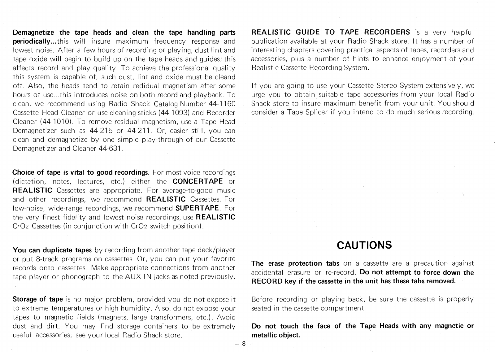
CAUTIONS
The erase protection tabs
on a cassette are a precaution against
accidental erasure or re-record.
Do not attempt to force down the
RECORD key if the cassette in the unit has these tabs removed.
Before recording or playing back, be sure the cassette is properly
seated in the cassette compartment.
Do not touch the face of the Tape Heads with any magnetic or
metallic object.
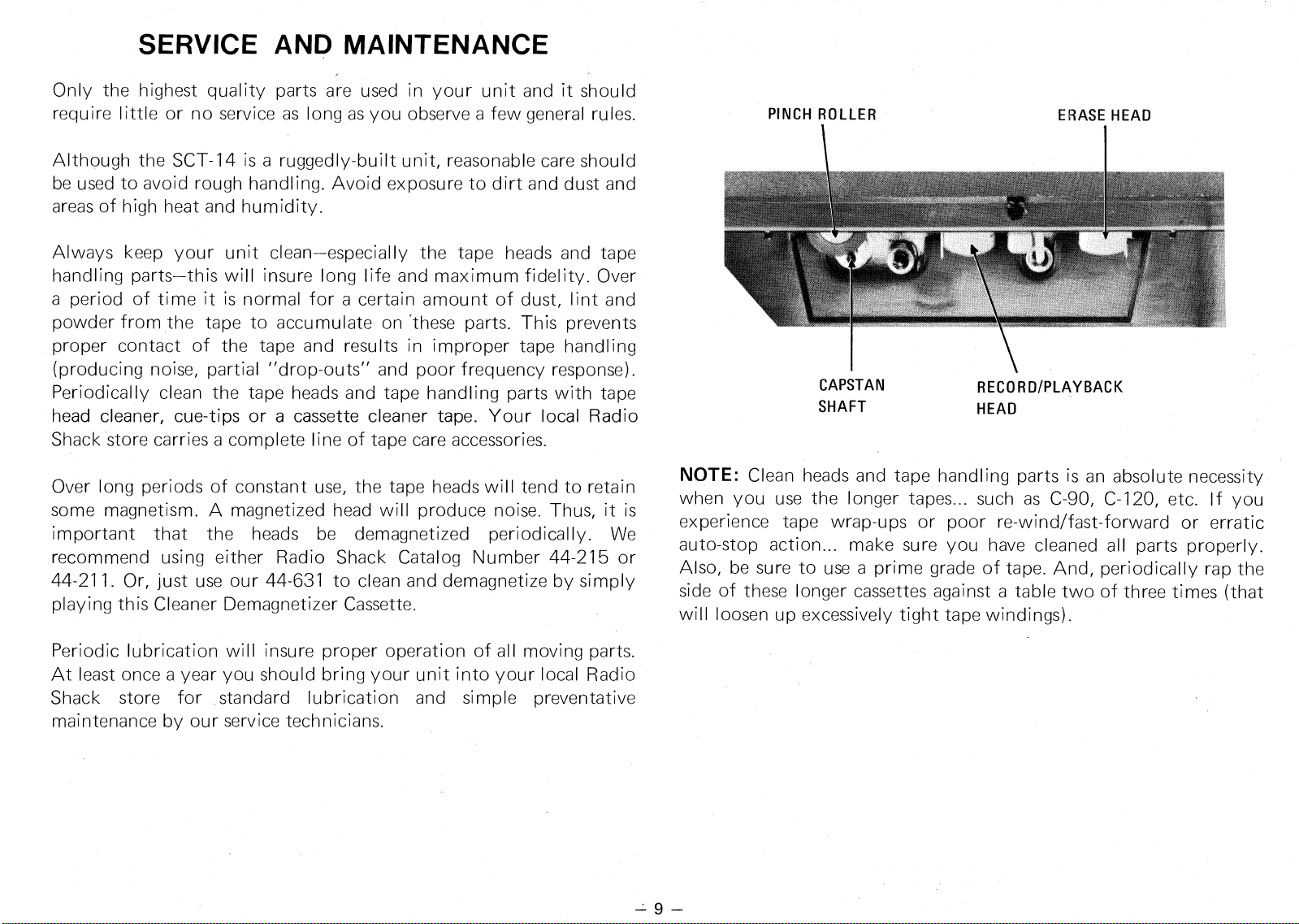
PINCH ROLLER
ERASE HEAD
CAPSTAN
RECORD/PLAYBACK
SHAFT
HEAD
SERVICE AND MAINTENANCE
Only the highest quality parts are used in your unit and it should
require little or no service as long as you observe a few general rules.
Although the SCT-14 is a ruggedly-built unit, reasonable care should
be used to avoid rough handling. Avoid exposure to dirt and dust and
areas of high heat and humidity.
Always keep your unit clean—especially the tape heads and tape
handling parts—this will insure long life and maximum fidelity. Over
a period of time it is normal for a certain amount of dust, lint and
powder from the tape to accumulate on 'these parts. This prevents
proper contact of the tape and results in improper tape handling
(producing noise, partial "drop-outs" and poor frequency response).
Periodically clean the tape heads and tape handling parts with tape
head cleaner, cue-tips or a cassette cleaner tape. Your local Radio
Shack store carries a complete line of tape care accessories.
Over long periods of constant use, the tape heads will tend to retain
some magnetism. A magnetized head will produce noise. Thus, it is
important that the heads be demagnetized periodically. We
recommend using either Radio Shack Catalog Number 44-215 or
44-211. Or, just use our 44-631 to clean and demagnetize by simply
playing this Cleaner Demagnetizer Cassette.
Periodic lubrication will insure proper operation of all moving parts.
At least once a year you should bring your unit into your local Radio
Shack store for standard lubrication and simple preventative
maintenance by our service technicians.
NOTE:
Clean heads and tape handling parts is an absolute necessity
when you use the longer tapes... such as C-90, C-120, etc. If you
experience tape wrap-ups or poor re-wind/fast-forward or erratic
auto-stop action... make sure you have cleaned all parts properly.
Also, be sure to use a prime grade of tape. And, periodically rap the
side of these longer cassettes against a table two of three times (that
will loosen up excessively tight tape windings).
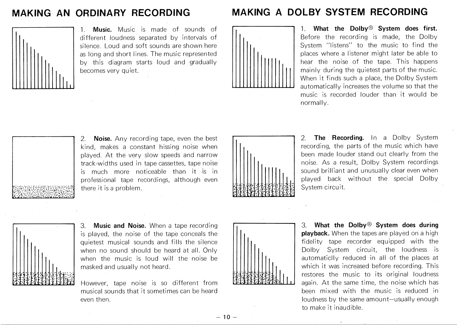
2.
Noise.
Any recording tape, even the best
kind, makes a constant hissing noise when
played. At the very slow speeds and narrow
track-widths used in tape cassettes, tape noise
is much more noticeable than it is in
professional tape recordings, although even
there it is a problem.
3.
Music and Noise.
When a tape recording
is played, the noise of the tape conceals the
quietest musical sounds and fills the silence
when no sound should be heard at all. Only
when the music is loud will the noise be
masked and usually not heard.
However, tape noise is so different from
musical sounds that it sometimes can be heard
even then.
MAKING AN ORDINARY RECORDING
MAKING A DOLBY SYSTEM RECORDING
1. Music. Music is made of sounds of
different loudness separated by intervals of
silence. Loud and soft sounds are shown here
as long and short lines. The music represented
by this diagram starts loud and gradually
becomes very quiet.
— 10—
1.
What the Dolby® System does first.
Before the recording is made, the Dolby
System "listens" to the music to find the
places where a listener might later be able to
hear the noise of the tape. This happens
mainly during the quietest parts of the music.
When it finds such a place, the Dolby System
automatically increases the volume so that the
music is recorded louder than it would be
normally.
2.
The Recording.
In a Dolby System
recording, the parts of the music which have
been made louder stand out clearly from the
noise. As a result, Dolby System recordings
sound brilliant and unusually clear even when
played back without the special Dolby
System circuit.
3.
What the Dolby® System does during
playback.
When the tapes are played on a high
fidelity tape recorder equipped with the
Dolby System circuit, the loudness is
automaticlly reduced in all of the places at
which it was increased before recording. This
restores the music to its original loudness
again. At the same time, the noise which has
been mixed with the music is reduced in
loudness by the same amount—usually enough
to make it inaudible.
••
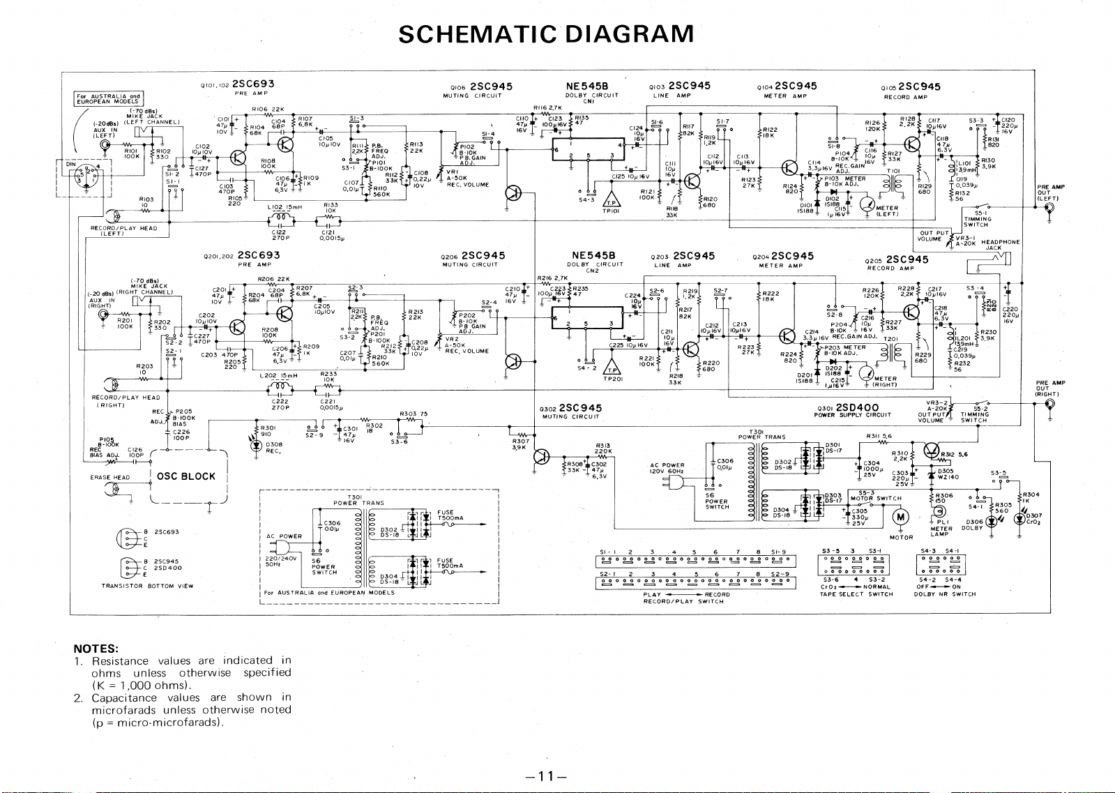
SCHEMATIC DIAGRAM
Q
101,102 2SC693
PRE AMP
Q103 2SC945
LINE AMP
QI04 2SC945
METER AMP
NE545B
DOLBY CIRCUIT
CNI
0105 2SC945
RECORD AMP
0106
2SC945
MUTING CIRCUIT
For
RII6 2,7K
R106
22K
;Z) dBs)
„,K
r
(-20(1150 (LEFT CHANNEL)
AUX IN
(LEFT)
R107
6.8K +
10(V1
3
6V
I6V
R128
CIO
47yffi
10V
s3-3 + C120
o
==. -"
.
220p
I6V
R 131
CI 7
10,16V
C118
7
6.3
'1
V
Riot,
cat'
68K
RI26
120K
2,2K
RI22
SI- 4
18K
RII9
C105
10p 10V
o
o
SI-8
3
R
A
'
D
8
C
J
K4
:
GAIN
16
(1)v
i
"
).7
1:371K
o
T
P 8. GAIN
ADJ.
R113
4
3
'1' PRE.
ADJ.
*
P101
3-1
8- 100K
S
R112
C107
33K
0.0Ip
RII0
560K
C102
22K
R101
IOOK
I
DIN
1
R102
10p10V
330
♦
fl
1
1
1
7
2
0
7
p •
F
3
2 1
3
2 ;
<
7
T
101
2
C112
C113
10,16V 10,16V
+
11_
RI30
I +pi
—
raZ
:L101
139mH
C119
0.039,
RI32
56
3,9K
C108
VRI
0.22.
A-50K
10V
REC, VOLUME
+
R109
p
1
6.3V -
CI25 10p I6V
+
8103
TEIER
S I - 1
--
1
==.
C103
o
i 0
470P
R105 ,
220
RI23
27K
RI29
680
On
AMP
(LEFT)
820
RI21
100K
D102 +
DIOI 15198
1
5
1S188 _
R103
RI20
S4
-
3
T.P
TP101
RI33
10K
680
L102_15mH
METER
(LEFT)
RII8
33K
S5-I
-1
Z1
'
7
'
;
j
1
G
RECORD/PLAY HEAD
(LEFT)
CI22
CI21
OUT PU
VOLUME
270P
0,0015p
VR3-I
-20K HEADPHONE
JACK
0201,2022SC693
PRE AMP
R206 22K
0206 2SC945
MUTING CIRCUIT
NE545B
DOL BY CIRCUIT
CN2
Q203
2SC945
LINE AMP
02042SC945
METER AMP
A
V
Q205
2SC945
RECORD AMP
R216 2,7K
(-
,,E
dBs)
„
JACK
(_20 ,Bs)
(RIGHT
CHANNEL)
R207
6.8K
47,
C2I0.
_
IOOy 16
S2-4
I
6
V ,
C201 +
47p
R204
10V
C202
R202
10p1OV
330
I
Ef
t
•
52 2 T
5
g
7
P •
S2,7
0
R222
ISK
47
(,2
1
1HT
I
)
N
C205
C220
220p
I6V
P204
10
1-1
S2-8
C2
-
I6
C2I4
8-10K = 16 V _ 33K
3.3.16V REC.GA)N ADJ. T20)
8202
*
I
fg GAIN
°K
ADJ.
10p1OV
R213
2.
P.B.
ADJ.
P201
8-100K
8212
R2I0
560K
22K
R201
C2I3
10,I6V
R223
27K
100K
S3-2
VR2
A-50K
REC, VOLUME
R209
1K
P203 METER
B-10K ADJ,
C206
47p
6.3V - -
S2 1
C203 470P
R205
220
C207
10V
R224
0,01,
820
R203
Fag
C215
10
R233
D201
L202 15mH
METER
-
(RIGHT)
10K
15188
PRE AMP
OUT
(RIGHT)
RECORD/PLAY HEAD
( RIGHT)
C222
C22I
VR3-2
0301
2SD400
POWER SUPPLY CIRCUIT
Q302 2SC 945
MUTING CIRCUIT
0.0015p
270P
A-20K
S5-2
OUT PUT
TIMMING
VOLUME
SWITCH
•
REC
ADJ.
P205
8
-
100K
BIAS
R303 75
F202
T301
PO
WER TRANS
R3I I 5,6
IOOP
).p
OSC BLOCK
R307
REC IO K
BIAS ADJ.
D301
R3 )3
3.9K
DS-17
220K
R3I0
4.
•
c304
22K
10
.
5V
Cq,p
2
sm
25V ,
R3I2 5.6
SSS
1R3084 C302
33K - 47
.
A.i
6v
E
DS 18
D3
z,
05
w4.
s3
a
,
ERASE HEAD
r
55-3
MOTOR SWITCH
C305
330p
25V
R304
IK
D307
CrO,
D303
T301
POWER TRANS
I C306
"`” 0.01p
of
•
o
c=
52 o
,
S6
qq
q
o
rr
T
1
510mA
a
DS
E
9113
I
J L
J
R305
S4- I
•
FUSE
I T500mA
PL I
D306
METER DOLBY
LAMP
L
J L
B 2SC693
AC POWER
MOTOR
3
S3-)
S3
-
5
S4-3
S4 -I
SI- I
2
3
4
5
6
7
8
SI-9
°°°°
°.2
°
O
000000000
220/240V
50Hz
° 2.2 °
00000's)
°°
° ,°=2
°
°
°
°
°
B 2SC945
C 2SD400
S2- 1
2
3
4
5
6
7
8
52-9
I
°
°
° ° ° ° ° °
I
OOO OOOOOO
S3-6 4 S3-2
CrOz-•--•--NORMAL
TAPE SELECT SWITCH
54-2 S4-4
DOLBY NR SWITCH
TRANSISTOR BOTTOM VIEW
For AUSTRALIA and EUROPEAN MODELS
PLAY f~ RECORD
RECORD/PLAY SWITCH
NOTES:
1.
Resistance values are indicated in
ohms unless otherwise specified
(K = 1,000 ohms).
2.
Capacitance values are shown in
microfarads unless otherwise noted
(p = micro-microfarads).
RADIO SHACK
r
i
g A DIVISION OF TANDY CORPORATION
U.S.A.: FORT WORTH, TEXAS 76102
CANADA: BARRIE, ONTARIO, CANADA L4M 4W5
TANDY CORPORATION
AUSTRALIA
BELGIUM
U. K.
280-316 VICTORIA ROAD
PARC INDUSTRIEL DE NANINNE
BILSTON ROAD
6A6
RYDALMERE, N.S.W. 2116
5140 NANINNE
WEDNESBURY, STAFFS WS10 7JN
Printed in Japan