
TXVR 3.8-10kVA Online Voltage
Regulator with Isolaon
Transformer
3.8kVA, 5kVA, 6kVA, 10kVA Models
User & Installaon Manual
www.xpcc.com | © 2018 Xtreme Power Conversion Corporaon. All rights reserved. (Rev 12/11/18)

Xtreme Power Conversion Corporaon
TXVR 3.8- 10kVA User’s Manual
Page 2
Uninterrupble Power Supply
Table of Contents
1 Safety and EMC Instrucons.......................................................................4
1.1 Transportaon and Storage...................................................................................................... 4
1.2 Preparaon............................................................................................................................... 4
1.3 Installaon................................................................................................................................ 4
1.4 Connecon .............................................................................................................................. 4
1.5 Maintenance............................................................................................................................ 4
1.6 Operaon................................................................................................................................. 5
1.7 Standards..................................................................................................................................6
2 Installaon ...............................................................................................7
2.1 Unpacking and inspecon..........................................................................................................7
2.2 Rear Panel View.........................................................................................................................8
2.3 Voltage Regulator Electrical Connecons/Installaon...............................................................9
3 Operaons..............................................................................................11
3.1 User Interface.........................................................................................................................11
3.1.1 Buon Operaon......................................................................................................11
3.1.2 LED Indicators...........................................................................................................11
3.1.3 LCD Panel.................................................................................................................12
3.1.5 Operang Mode/ Descripons................................................................................ 13
3.2 Voltage Regulator Operaon..................................................................................................15
3.3 LCD Sengs............................................................................................................................17
4 Trouble Shoong......................................................................................23
4.1 Audible Alarm..........................................................................................................................23
4.2 Warning Indicator....................................................................................................................23
4.3 Warning Code Descripons.....................................................................................................23
4.4 Fault Code Descripons...........................................................................................................24
4.5 Trouble Shoong Chart...........................................................................................................25

Xtreme Power Conversion Corporaon
TXVR 3.8- 10kVA User’s Manual
Page 3
Uninterrupble Power Supply
5 Specicaons..........................................................................................26
6 Obtaining Service....................................................................................27
7 Xtreme Power Conversion Limited Warranty.............................................28
8 Xtreme Power Load Protecon Policy......................................................29

Xtreme Power Conversion Corporaon
TXVR 3.8- 10kVA User’s Manual
Page 4
Uninterrupble Power Supply
1 Safety Informaon
Please read carefully the following user manual and the safety instrucons before installing the Voltage Regulator
or using the Voltage Regulator! Please comply with all warnings and operang instrucons in this manual. Save
this manual and read carefully the following instrucons before installing the unit. Do not operate this unit before
reading through all safety informaon and operang instrucons carefully.
1.1 Transportaon and Storage
• Please transport the Voltage Regulator only in the original packaging to protect against shock and impact.
• The Voltage Regulator must be stored in a room where it is venlated and dry.
1.2 Preparaon
• Condensaon may occur if the Voltage Regulator is moved directly from cold to warm environments. The
Voltage Regulator must be absolutely dry before being installed. Please allow at least two hours for the
Voltage Regulator to acclimate to the environment.
• Do not install the Voltage Regulator near water or in moist environments.
• Do not install the Voltage Regulator where it would be exposed to direct sunlight or nearby heaters.
• Do not block venlaon holes in the Voltage Regulator housing.
1.3 Installaon
• Do not connect appliances or devices which would overload the Voltage Regulator (e.g. motor-type
equipment) to the Voltage Regulator output receptacles or terminal.
• Place cables in such a way that no one can step on or trip over them.
• Do not block air vents in the housing of the system components. The Voltage Regulator must be installed
in a locaon with good venlaon. Ensure enough space on each side for venlaon.
• Voltage Regulator has provided a ground terminal for equipotenal earth bonding to the external Volt-
age Regulator baery cabinets in the nal installed system conguraon.
• The Voltage Regulator can be installed only by qualied maintenance personnel.
• An appropriate disconnect device for short-circuit backup protecon should be provided in the building
wiring installaon, upstream of the Voltage Regulator.
• An integral single emergency switching device which prevents further supply to the load by the Voltage
Regulator in any mode of operaon should be provided in the building wiring installaon.
• Connect the ground before connecng to the building wiring terminal.
• Installaon and wiring must be performed in accordance with the local electrical laws and regulaons.
1.4 Connecon
• This Voltage Regulator must be installed and grounded in accordance with local and naonal electrical
code.
• The power supply for this unit must be single-phase rated in accordance with the equipment nameplate.
It also must be suitably grounded.
• There can be no derivaon in the line that goes from the Backfeed Protecon to the Voltage Regulator,
as the standard safety would be infringed.
• The power supply for this unit must be single-phase rated in accordance with the equipment nameplate..
WARNING
HIGH LEAKAGE CURRENT
EARTH CONNECTION ESSENTIAL
BEFORE CONNECTING SUPPLY

Xtreme Power Conversion Corporaon
TXVR 3.8- 10kVA User’s Manual
Page 5
Uninterrupble Power Supply
• Use of this equipment in life support applicaons where failure of this equipment can reasonably be expected
to cause the failure of the life support equipment or to signicantly aect its safety or eecve-ness is not
recommended. Do not use this equipment in the presence of a ammable anesthec mixture with air, oxygen or
nitrous oxide.
• Connect your Voltage Regulator power module’s grounding terminal to a grounding electrode conductor.
• Warning labels should be placed on all primary power switches installed in places away from the device to alert
the electrical maintenance personnel of the presence of a Voltage Regulator in the circuit. The label will bear the
following or an equivalent text:
Before working on this circuit
Isolate Uninterrupble Power Supply (Voltage Regulator) Then check for Hazardous Voltage between
all terminals including the protected ground
Risk of Voltage Backfeed
1.5 Maintenance
• Before carrying out any kind of service or maintenance, verify that no current is present and no
hazardous voltage exists on the terminals.
• Please remove all wristwatches, rings and other metal personal objects before maintenance or
repair, and only use tools with insulated grips and handles for maintaining or repairing.
• Please replace the fuse only with the same type and amperage in order to avoid re hazards.
• Do not disassemble the Voltage Regulator.
1.6 Operaon
• Do not disconnect the ground conductor cable on the Voltage Regulator or the building wiring
terminals in any me since this would cancel the protecve ground of the Voltage Regulator and of all
connected loads.
• In order to fully disconnect the Voltage Regulator, rst press the “OFF” buon and then disconnect the
mains.
• Ensure that no liquid or other foreign objects can enter into the Voltage Regulator.
• The Voltage Regulator can be operated by any individuals with no previous experience.
Xtreme Power Conversion Corporaon
TXVR 3.8- 10kVA User’s Manual
Page 6
Uninterrupble Power Supply
1.7 Standards
* Safety
Safety Conformance: IEC/EN 62040-1,UL1778 (5th Edion)
Safety Markings : cTUVus, CE
* EMI
Conducted Emission..............................:IEC/EN 62040-2,FCC PART15 CLASS A
Radiated Emission.................................:IEC/EN 62040-2,FCC PART15 CLASS A
*EMS
ESD.........................................................:IEC/EN 61000-4-2 Level 4
RS........................................................ ...:IEC/EN 61000-4-3 Level 3
EFT......................................................... :IEC/EN 61000-4-4 Level 4
SURGE................................................... :IEC/EN 61000-4-5 Level 4
CS........................................................... :IEC/EN 61000-4-6 Level 3
Power-frequency Magnec eld.............. :IEC/EN 61000-4-8 Level 4
Low Frequency Signals............................:IEC/EN 61000-2-2
Warning: This is a product for commercial and industrial applicaon in the second environment-installaon re-
stricons or addional measures may be needed to prevent disturbances.

Xtreme Power Conversion Corporaon
TXVR 3.8- 10kVA User’s Manual
Page 7
Uninterrupble Power Supply
2 Installaon
2.1 Unpacking and Inspecon
Unpack the package and check the package contents. The shipping package contains:
● One Voltage Regulator
● One user manual
● One monitoring soware CD
● One RS-232 cable (opon)
● One USB cable
● One share current cable (only available for parallel model)
NOTE: Before installaon, please inspect the unit. Be sure that nothing inside the package is damaged during trans-
portaon. Do not turn on the unit and nofy the carrier and dealer immediately if there is any damage or lacking
of some parts. Please keep the original package in a safe place for future use.
Xtreme Power Conversion Corporaon
TXVR 3.8- 10kVA User’s Manual
Page 8
Uninterrupble Power Supply
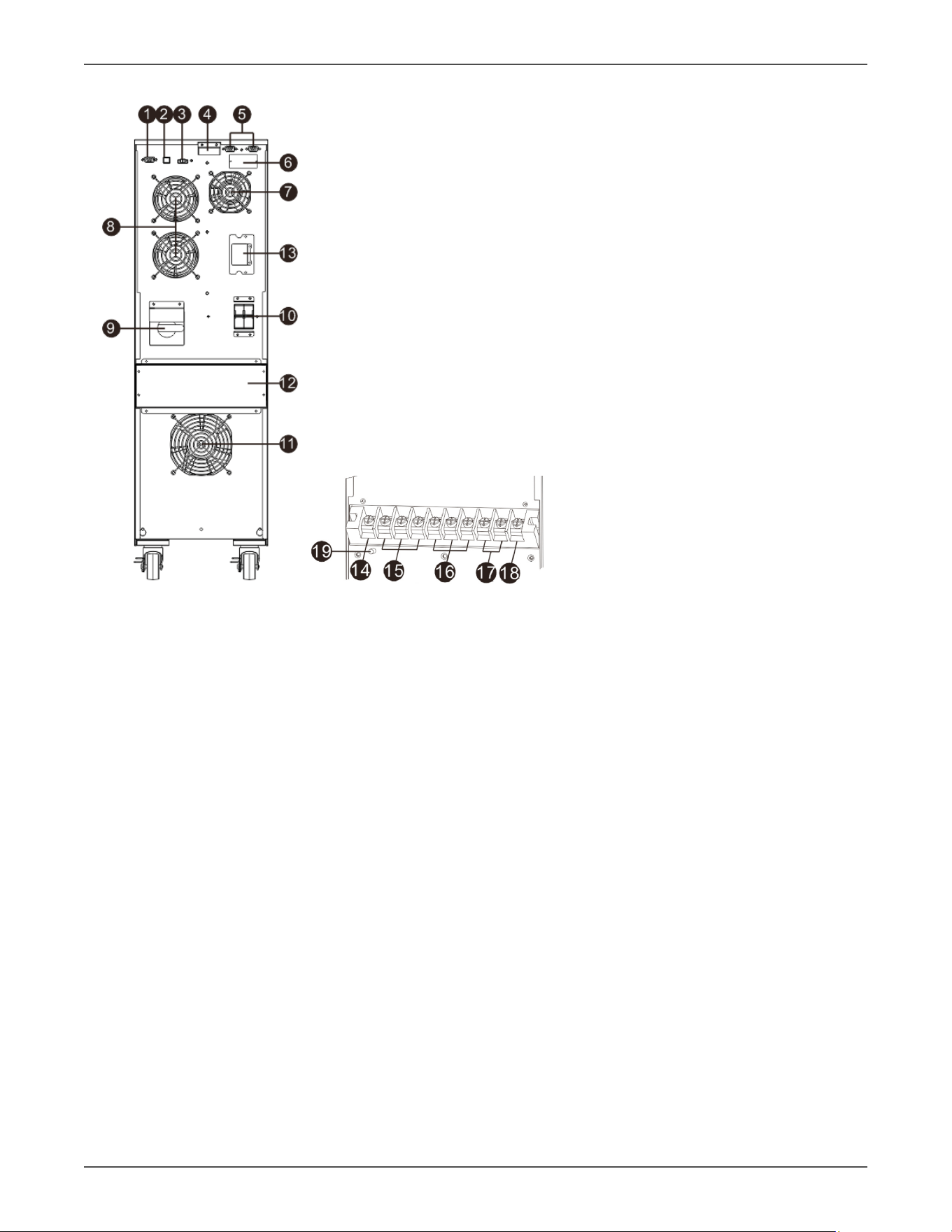
2.2 Rear Panel View
Diagram 1: Rear Panel Overlook Diagram 2: Input/Output Terminal
1. RS-232 communicaon port
2. USB communicaon port
3. Emergency power o funcon connector (EPO connector)
4. Share current port (only available for parallel model)
5. Parallel port (only available for parallel model)
6. Intelligent slot
7. Charger fan
8. Power stage fan
9. Maintenance bypass switch
10. Input circuit breaker
11. Isolaon transformer fan
12. Input/Output terminal (Refer to Diagram 2 for the details)
13. External baery connector
14. Non-isolated neutral
15. ISO TAP selecons
16. Output
17. Input
18. Input ground
19. Output ground
Xtreme Power Conversion Corporaon
TXVR 3.8- 10kVA User’s Manual
Page 9
Uninterrupble Power Supply
2.3 Voltage Regulator Electrical Connecons/Installaon
Installaon and wiring must be performed in accordance with the local electric laws/regulaons and the following
instrucons must be performed by qualied personnel
1. Make sure the mains wire and breakers in the building are sized for the rated capacity of
Voltage Regulator to avoid the hazards of electric shock or re.
2. Switch o the mains switch in the building before installaon.
3. Turn o all the connected devices before connecng to the Voltage Regulator.
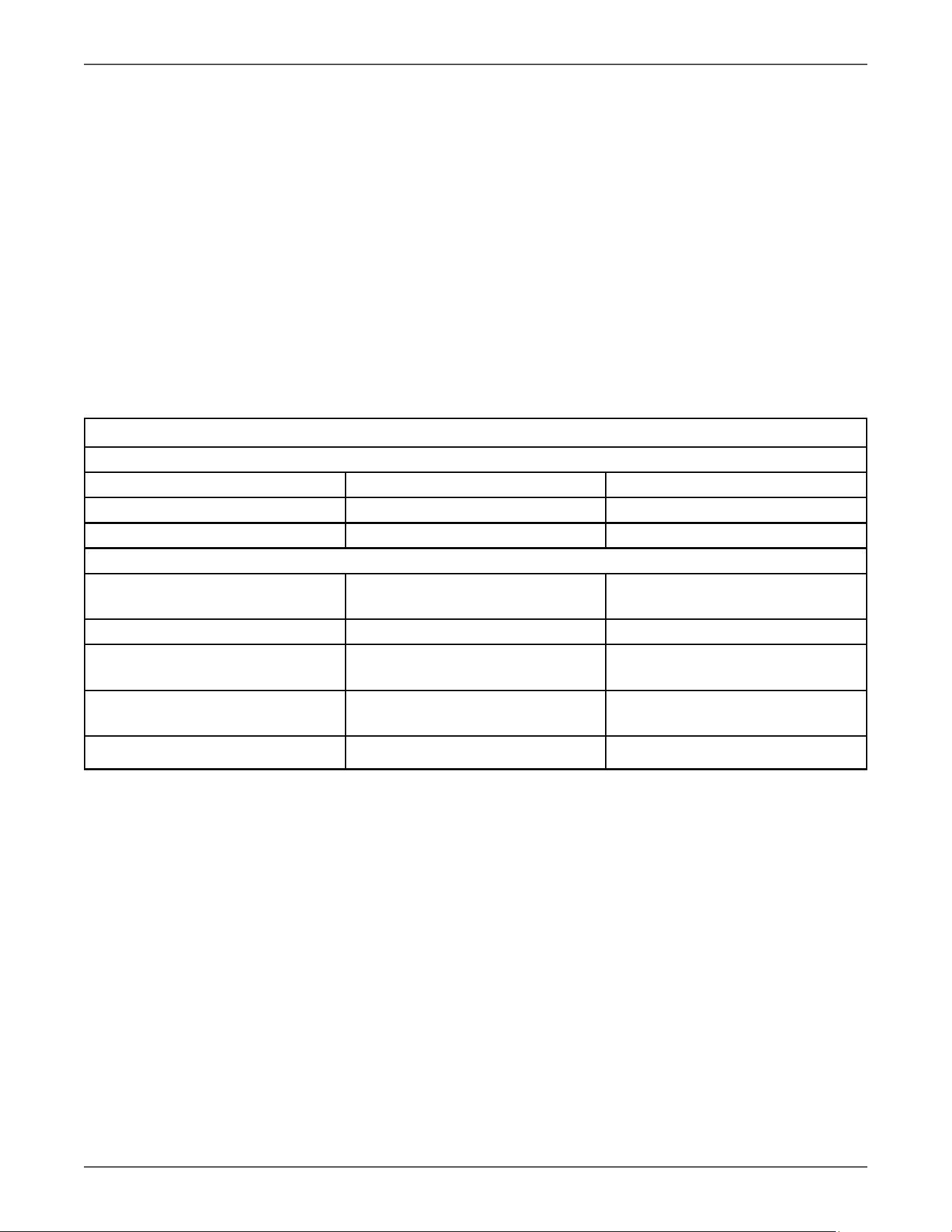
4. Prepare wiring based on the following table:
Model Wiring spec (AWG)
Input Output Ground
3.8kVA 10 10 8
5kVA 8 8 8
6kVA 6 6 6
10kVA 4 4 4
Model Recommended Input Overcurrent Protecon
3.8kVA 30A
5kVA 30A
6kVA 40A
10kVA 70A
NOTE: The selecons for size and color of wires should follow the local electrical laws and regulaons.
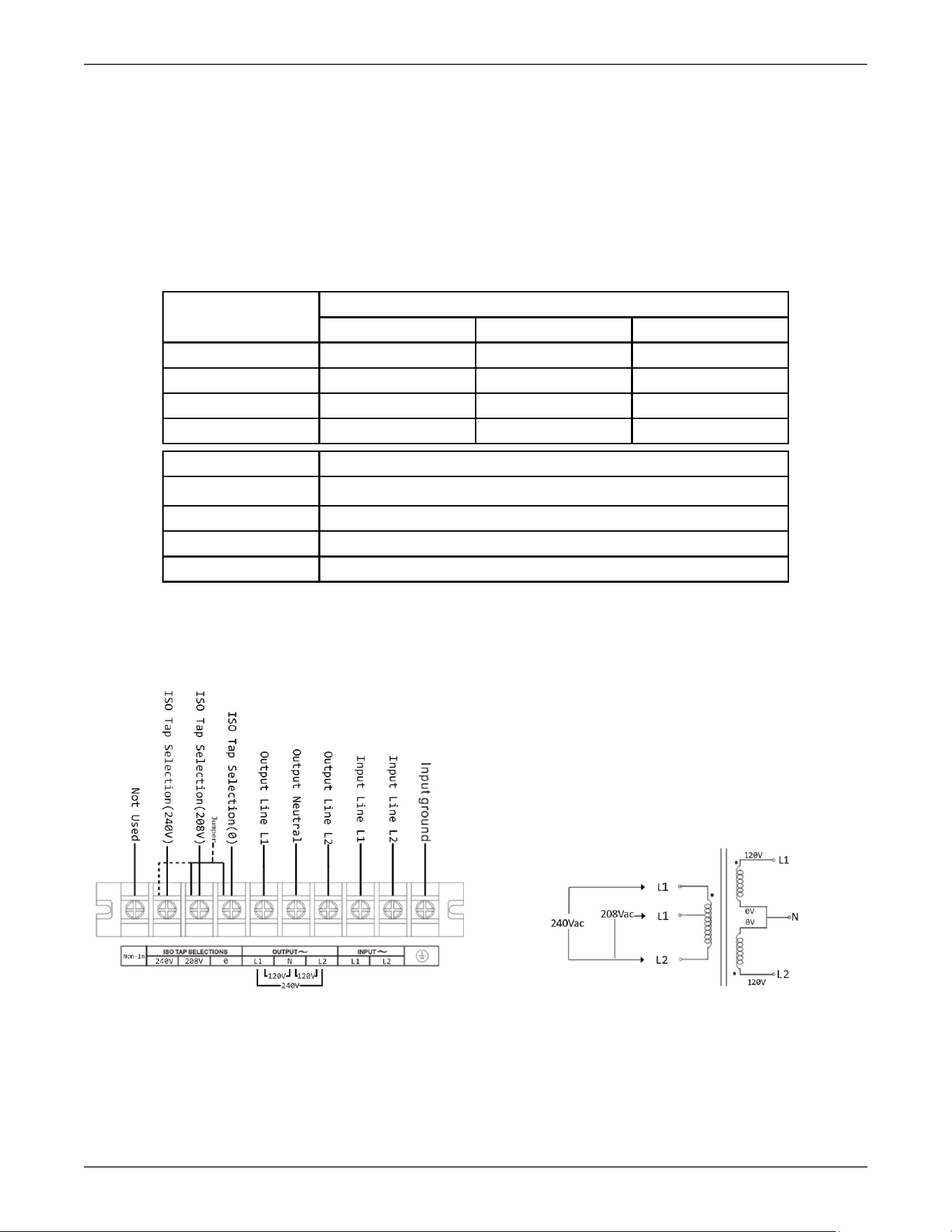
5. Remove the terminal block cover on the rear panel of Voltage Regulator
Follow below steps to connect the wire
Voltage Regulator Terminal Block Wiring Diagram Voltage Regulator Transformer Diagram
Figure 2-3 Figure 2-4
Xtreme Power Conversion Corporaon
TXVR 3.8- 10kVA User’s Manual
Page 10
Uninterrupble Power Supply
1. Connect input L1 wire to Voltage Regulator input L1 terminal.
2. Connect input L2 wire to Voltage Regulator input L2 terminal.
3. Connect input GND wire to input GND terminal.
4. Connect output L1 wire to Voltage Regulator output L1 terminal.
5. Connect output L2 wire to Voltage Regulator output L2 terminal.
6. Connect output N wire to Voltage Regulator N terminal.
7. Ensure ISO TAP Jumper is in correct posion (208V for 208V input or 240V for any other
input voltages).
8. Ensure Output voltage parameter is set to match the site input voltage. Refer to secon
3.3
NOTE 1: The ISO Tap Selector Jumper is electrically located between the output of the inverter and the
transformer primary. In the 208V posion it steps up the voltage by 11%. In the 240v posion there is
no voltage change. 208V is default Posion. Refer to gure 2-4.
Voltage Conguraon Chart
Standard Sengs
Input Voltage Iso Tap Posion Voltage Out
208 208 240/120V (Default)
240 240 240/120
Addional Sengs
200 208
240
222/111
220/110
208 240 208/104
220 208
240
244/122
220/110
230 208
240
256/128
230/115
240 208 266/133
NOTE 1: If other than default seng is desired, conguraon can be done at the factory for an
addional voltage conguraon fee.
6. Aer connecng the wires, replace the terminal block cover on the rear panel of the Voltage
Regulator.
NOTE 1: Install the output breaker between the output terminal and the Load. I.A.W NEC code.
NOTE 2: Voltage Regulator Cabinet contains an Isolaon Transformer with N-G bond. This system
qualies as a separately derived source.
Warning:
Make sure the Voltage Regulator is turned o before installaon.
The Voltage Regulator should not be turned on during wiring connecon.
Xtreme Power Conversion Corporaon
TXVR 3.8- 10kVA User’s Manual
Page 11
Uninterrupble Power Supply
Soware Installaon
For opmal computer system protecon, install Voltage Regulator monitoring soware to fully
congure Voltage Regulator.
3 Operaons
3.1 User Interface
3.1.1 Buon Operaon
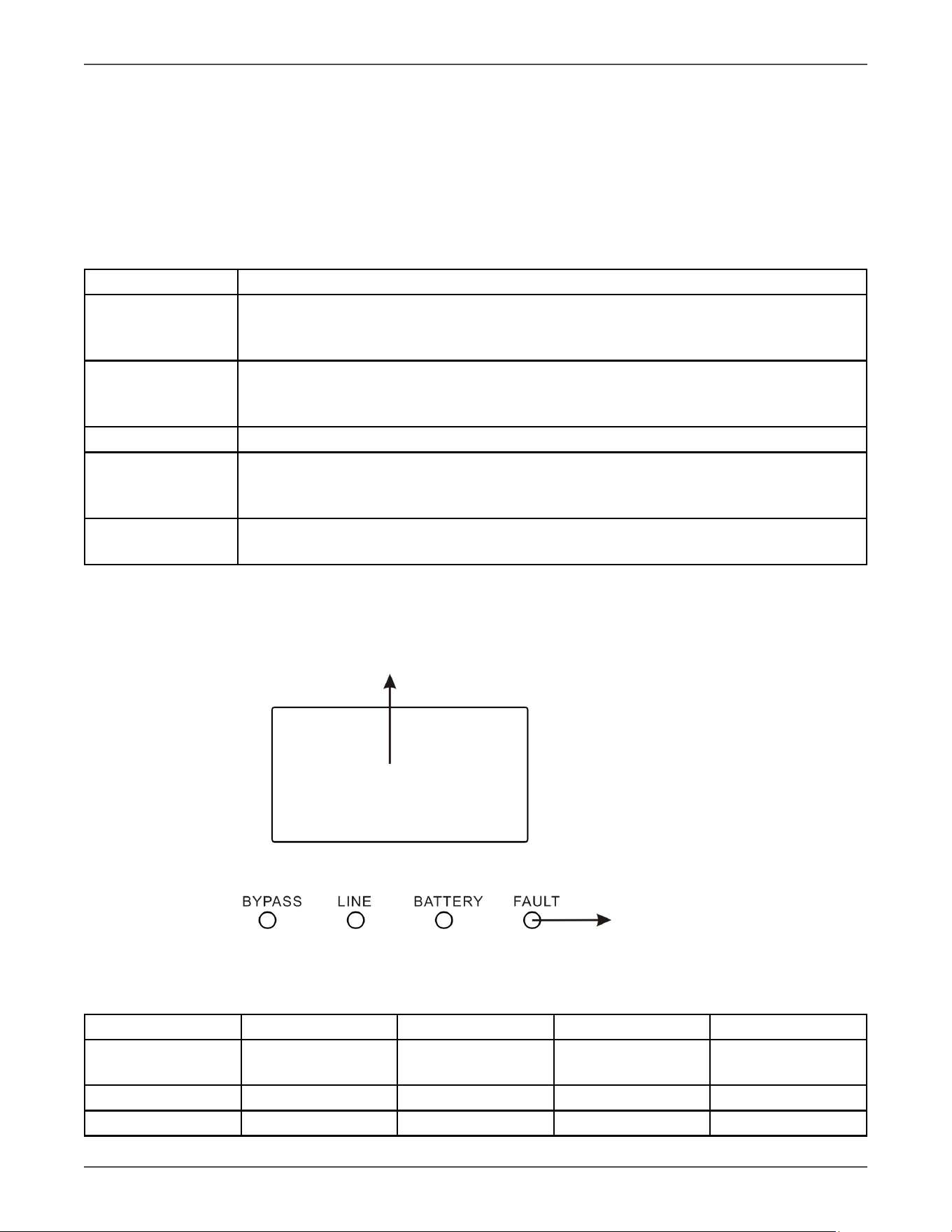
Buon Funcon
ON/Enter Buon Turn on the Voltage Regulator: Press and hold the buon more than 0.5s to turn on the
Voltage Regulator.
Enter Key: Press this buon to conrm the selecon in seng menu.
OFF/ESC Buon Turn o the Voltage Regulator: Press and hold the buon more than 0.5s to turn o the
Voltage Regulator.
Esc key: Press this buon to return to last menu in seng menu.
Test/Up Buon UP key: Press this buon to display next selecon in seng menu.
Mute/Down Buon Mute the alarm: Press and hold the buon more than 0.5s to mute the buzzer. Please refer
to secon 3-4-9 for details.
Down key: Press this buon to display previous selecon in seng menu.
Test/Up + Mute/
Down Buon
Press and hold the two buons simultaneous more than 1s to enter/escape the seng
menu.
* CVCF mode means converter mode.
3.1.2 LED Indicators
LCD Panel
LED indicators
LCD Panels and LED Indicators
Figure 3-1
There are 4 LEDs on front panel to show the Voltage Regulator working status:
Mode LED Bypass Line Baery Fault
Voltage Regulator
Startup
● ● ● ●
No Output mode ○ ○ ○ ○
Bypass mode ● ○ ○ ○
Xtreme Power Conversion Corporaon
TXVR 3.8- 10kVA User’s Manual
Page 12
Uninterrupble Power Supply
AC mode ○ ● ○ ○
CVCF mode ○ ● ○ ○
ECO mode ● ● ○ ○
Fault ○ ○ ○ ●
Note: ● means LED is lighng, and ○ means LED is faded.
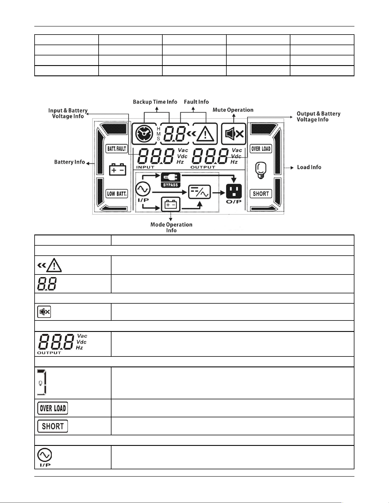
3.1.3 LCD Panel:
Display Funcon
Fault informaon
Indicates that the warning and fault occurs.
Indicates the fault codes, and the codes are listed in details in secon 3-9.
Mute operaon
Indicates that the Voltage Regulator alarm is disabled.
Output & Baery voltage informaon
Indicates the output voltage, frequency or baery voltage.
Vac: output voltage, Vdc: baery voltage, Hz: frequency
Load informaon
Indicates the load level by 0-25%, 26-50%, 51-75%, and 76-100%.
Indicates overload.
Indicates the load or the output is shorted.
Mode operaon informaon
Indicates the Voltage Regulator connects to the mains.
Xtreme Power Conversion Corporaon
TXVR 3.8- 10kVA User’s Manual
Page 13
Uninterrupble Power Supply
Indicates the bypass circuit is working.
Indicates the ECO mode is enabled.
Indicates the Inverter circuit is working.
Indicates the output is working.
Input & Baery voltage informaon
Indicates the input voltage or frequency or baery voltage.
Vac: Input voltage, Vdc: baery voltage, Hz: input frequency
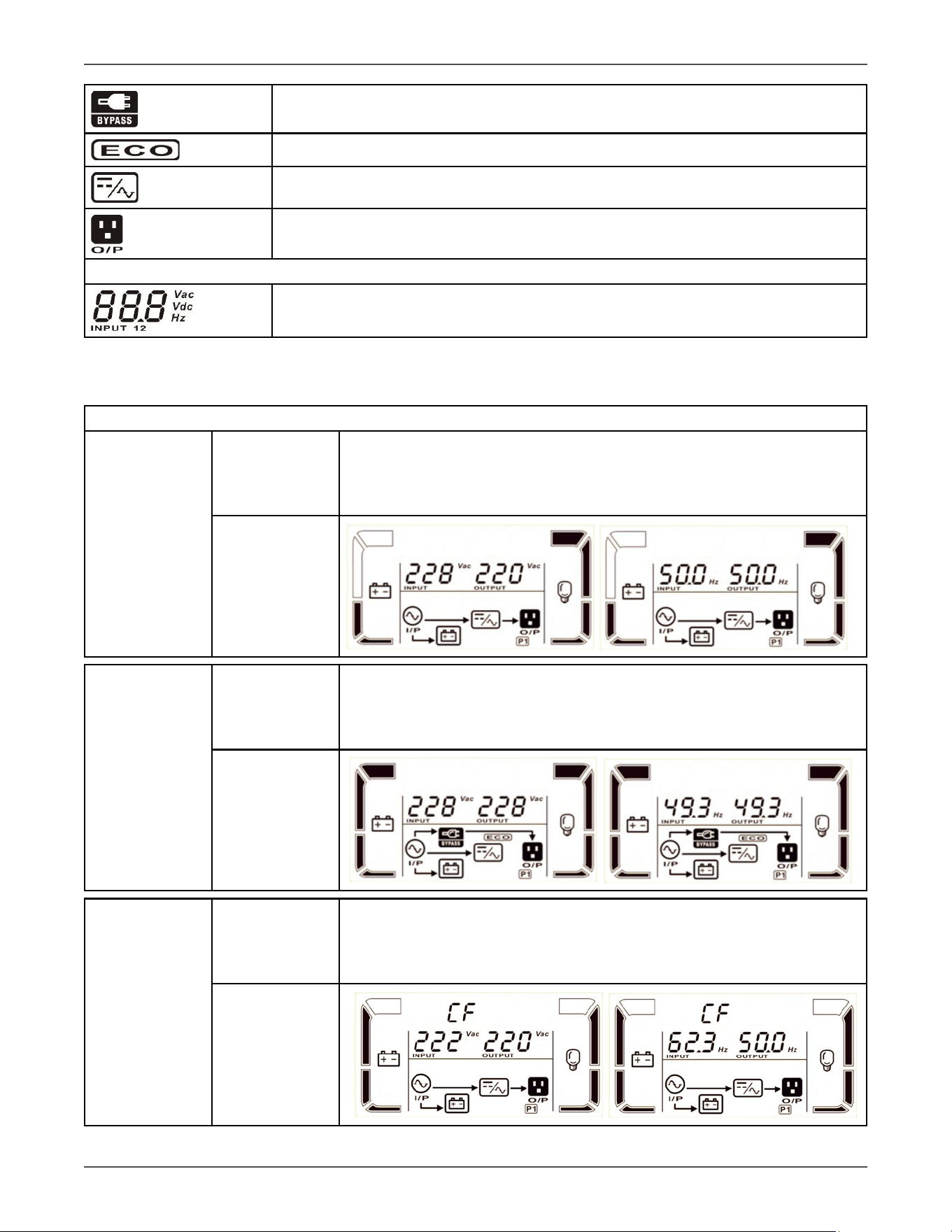
3.1.5 Operang Mode/Descripons
Operang mode/status
AC mode Descripon
When the input voltage is within acceptable range, Voltage Regulator will
provide pure and stable AC power to output. The Voltage Regulator will
also charge the baery at AC mode.
LCD display
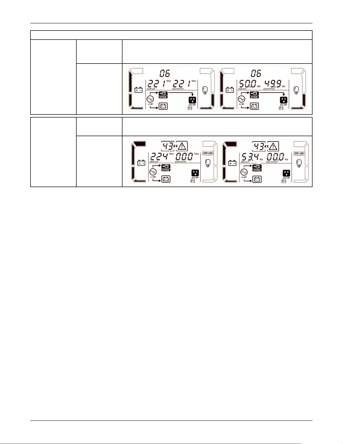
ECO mode Descripon
When the input voltage is within voltage regulaon range and ECO mode is
enabled, Voltage Regulator will bypass voltage to output for energy saving.
LCD display
CVCF mode Descripon
When input frequency is within 46 to 64Hz, the Voltage Regulator can be
set at a constant output frequency, 50 Hz or 60 Hz. The Voltage Regulator
will sll charge baery under this mode.
LCD display
Xtreme Power Conversion Corporaon
TXVR 3.8- 10kVA User’s Manual
Page 14
Uninterrupble Power Supply
Operang mode/status
Bypass mode Descripon
When input voltage is within acceptable range and bypass is enabled, turn
o the Voltage Regulator and it will enter Bypass mode. Alarm beeps every
two minutes.
LCD display
Fault status Descripon
When a Voltage Regulator fault has happened, it will display fault messages
in LCD panel.
LCD display

Xtreme Power Conversion Corporaon
TXVR 3.8- 10kVA User’s Manual
Page 15
Uninterrupble Power Supply
3.2 Voltage Regulator Operaon
1. Turn on the Voltage Regulator with ulity power supply (in AC mode)
1. Aer power supply is connected correctly. Set the input breaker at “ON” posion. At this me
the fan is running and the Voltage Regulator supplies power to the loads via the bypass. The
Voltage Regulator is operang in Bypass mode.
NOTE: When Voltage Regulator is in Bypass mode, the output voltage will directly power from ulity aer you
switch on the input breaker. In Bypass mode, the load is not protected by Voltage Regulator. To protect your pre-
cious devices, you should turn on the Voltage Regulator. Refer to next step.
2. Press and hold the “ON” buon for 0.5s to turn on the Voltage Regulator and the buzzer will beep once.
3. A few seconds later, the Voltage Regulator will enter to AC mode.
Connect devices to Voltage Regulator
1. Turn on the Voltage Regulator rst and then switch on the devices one by one, the LCD panel will display
total load level.
2. If it is necessary to connect inducve loads such as a printer, the in-rush current should be
calculated carefully to ensure if it meets the capacity of the Voltage Regulator, because the power consump-
on of this kind of loads is too big.
3. If the Voltage Regulator is overloaded, the buzzer will beep twice every second.
4. When the Voltage Regulator is overloaded, please remove some loads immediately. It is
recommended to have the total loads connected to the Voltage Regulator less than 80% of its nominal power
capacity to prevent overload for system safety.
5. If the overload me is over an acceptable me listed in spec at AC mode, the Voltage Regulator
will automacally transfer to Bypass mode. Aer the overload is removed, it will return to AC
mode. At this me, if bypass is enabled, the Voltage Regulator will power the load via bypass.
If bypass funcon is disabled or the input power is not within bypass acceptable range, it will
cut o output directly.
Turn o the Voltage Regulator with ulity power supply in AC mode
1. Turn o the inverter of the Voltage Regulator by pressing “OFF” buon for at least 0.5s, and
then the buzzer will beep once. The Voltage Regulator will go into Bypass mode.
NOTE 1: If the Voltage Regulator has been set to enable the bypass output, it will bypass voltage
from ulity power to output sockets and terminal even though you have turned o the Voltage
Regulator (inverter).
NOTE 2: Aer turning o the Voltage Regulator, please be aware that the Voltage Regulator is
working in Bypass mode and there is risk of power loss for connected devices.
2. In Bypass mode, output voltage of the Voltage Regulator is sll present. In order to cut o the output,
switch o the input breaker. A few seconds later, there is no display shown on the display panel and Voltage
Regulator is completely o.
Mute the buzzer
1. To mute the buzzer, please press the “Mute” buon for at least 0.5s. If you press it again aer the buzzer is
muted, the buzzer will beep again.
2. Some warning alarms can’t be muted unless the error is xed.
Operaon in warning status

Xtreme Power Conversion Corporaon
TXVR 3.8- 10kVA User’s Manual
Page 16
Uninterrupble Power Supply
1. When Fault LED ashes and the buzzer beeps once every second, it means that there are some problems
for Voltage Regulator operaon. Users can get the warning code from LCD panel. Please check the trouble-
shoong chart in secon 4 for details.
Operaon in Fault mode
1. When Fault LED illuminates and the buzzer beeps connuously, it means that there is a fatal error in the
Voltage Regulator. Users can get the fault code from LCD panel. Please check the troubleshoong chart in
secon 4 for details.
2. Please check the loads, wiring, venlaon, ulity and so on aer the fault occurs. Don’t try to turn on
the Voltage Regulator again before solving the problems. If the problems can’t be xed, please contact the
distributor or service people immediately.
3. In case emergency case, please cut o the connecon from ulity and output immediately to avoid more
risk or danger.
Xtreme Power Conversion Corporaon
TXVR 3.8- 10kVA User’s Manual
Page 17
Uninterrupble Power Supply
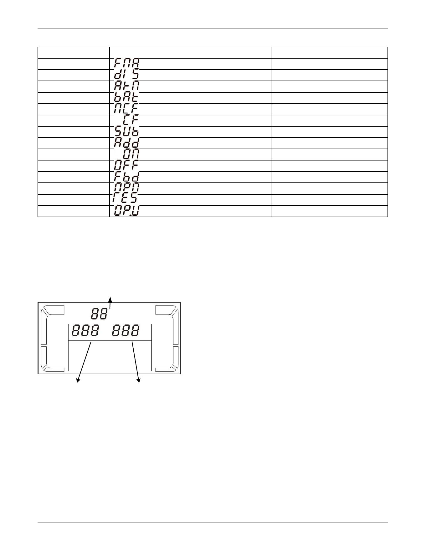
LCD Display Abbreviaons
Abbreviaon Display content Meaning
ENA Enable
DIS Disable
ATO Auto
BAT Baery
NCF Normal mode (not CVCF mode)
CF CVCF mode
SUB Subtract
ADD Add
ON On
OFF O
FBD Not allowed
OPN Allowed
RES Reserved
O P.V Output voltage
3.3 LCD Sengs
There are three parameters to set up the Voltage Regulator. Refer to following diagram.
Parameter 1
LCD Panel with Sengs
Figure 3.3
Parameter 1: It’s for program alternaves.
Parameter 2 and parameter 3 are the seng opons
or values for each program.
Parameter 2 Parameter 3
Xtreme Power Conversion Corporaon
TXVR 3.8- 10kVA User’s Manual
Page 18
Uninterrupble Power Supply
How to set parameters
1. Put the Voltage Regulator in Bypass mode by pressing and holding the OFF/ESC buon for over
5 seconds.
2. Press and hold the Test/Up + Mute/Down buons simultaneously. To enter seng mode.
3. Use the Up or Down buon to nd the Voltage Regulator parameter you wish to set.
4. Press the Enter buon to conrm the selecon
5. Use the Up or Down buon to select the desired value.
6. Press the Enter buon to conrm the selecon
7. Press and hold the Text/Up + Mute/Down buons simultaneously. To exit seng mode.
8. Cycle Voltage Regulator input power to save sengs.
Programs list for parameter 1:
Code Descripon Bypass AC ECO CVCF Baery Baery
Test
01 Output voltage Y
02 Output frequency Y
03 Voltage range for bypass Y
04 Frequency range for bypass Y
05 ECO mode enable/disable Y
06 Voltage range for ECO mode Y
07 ECO mode frequency range seng Y
08 Bypass mode seng Y
09 Reserved Reserved for future
10 Reserved Reserved for future
11 Hot standby funcon enable/disable Y Y Y Y Y Y
12 Inverter voltage adjustment Y Y Y
13 Output voltage calibraon Y Y Y
*Y means that this program can be set in this mode.
Note: All parameter sengs will be saved only when Voltage Regulator shuts down normally with internal or
external baery connecon. (Normal Voltage Regulator shutdown means turning o input breaker in bypass/no
output mode).
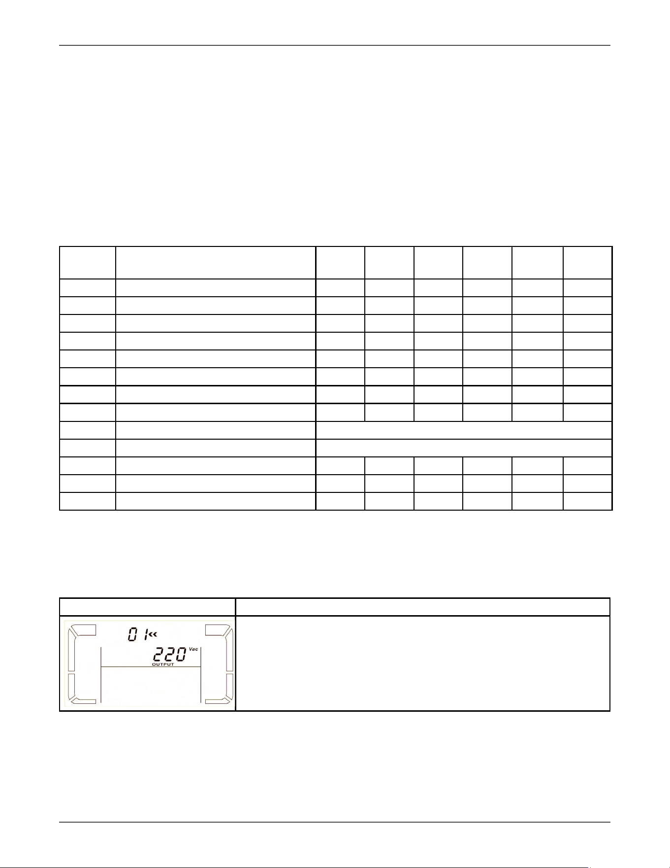
01: Output voltage
Interface Seng
Parameter 3: Output voltage
You may choose the following output voltage in parameter 3:
208: Presents output voltage is 208Vac
220: Presents output voltage is 220Vac
230: Presents output voltage is 230Vac
240: Presents output voltage is 240Vac
Xtreme Power Conversion Corporaon
TXVR 3.8- 10kVA User’s Manual
Page 19
Uninterrupble Power Supply
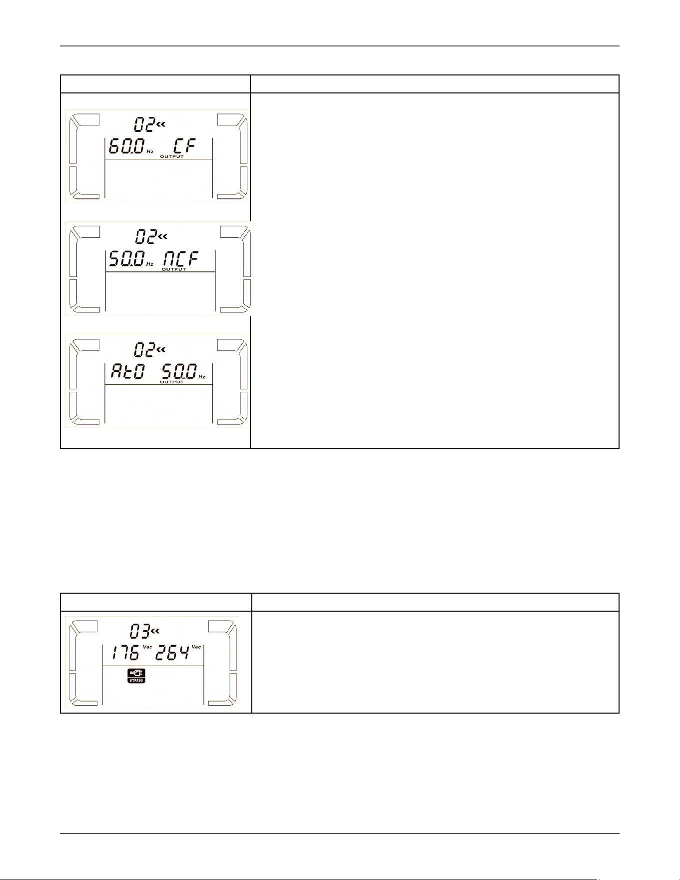
02: Output frequency
Interface Seng
60 Hz, CVCF mode
50 Hz, Normal mode
ATO
Parameter 2: Output Frequency
Seng the output frequency. You may choose following three opons in
parameter 2:
50.0Hz: The output frequency is seng for 50.0Hz.
60.0Hz: The output frequency is seng for 60.0Hz.
ATO: If selected, output frequency will be decided according to the latest
normal ulity frequency. If it is from 46Hz to 54Hz, the output frequency
will be 50.0Hz. If it is from 56Hz to 64Hz, the output frequency will be
60.0Hz. ATO is default seng.
Parameter 3: Frequency mode
Seng output frequency at CVCF mode or not CVCF mode. You may
choose following two opons in parameter 3:
CF: Seng Voltage Regulator to CVCF mode. If selected, the output fre-
quency will be xed at 50Hz or 60Hz according to seng in parameter 2.
The input frequency could be from 46Hz to 64Hz.
NCF: Seng Voltage Regulator to normal mode (not CVCF mode). If se-
lected, the output frequency will synchronize with the input frequency
within 46~54 Hz at 50Hz or within 56~64 Hz at 60Hz according to seng
in parameter 2. If 50 Hz selected in parameter 2, Voltage Regulator will
transfer to baery mode when input frequency is not within 46~54 Hz. If
60Hz selected in parameter 2, Voltage Regulator will transfer to baery
mode when input frequency is not within 56~64 Hz.
*If Parameter 2 is ATO, the Parameter 3 will show the current frequency.
Note: If the Voltage Regulator is set to CVCF mode, the bypass funcon will be disabled automacally.
But when a single Voltage Regulator is powered on with mains and before the Voltage Regulator n-
ished the startup, there will be a few seconds of voltage pulse (same as the input voltage) on the
bypass output.
If you need to remove the pulse on this mode to protect your load beer, you could contact the dealer
for help.
03: Voltage range for bypass
Interface Seng
Parameter 2: Set the acceptable low voltage for bypass. Seng range is
from 110V to 209V and the default value is 110V.
Parameter 3: Set the acceptable high voltage for bypass. Seng range is
from 231V to 276V and the default value is 264V.
Xtreme Power Conversion Corporaon
TXVR 3.8- 10kVA User’s Manual
Page 20
Uninterrupble Power Supply
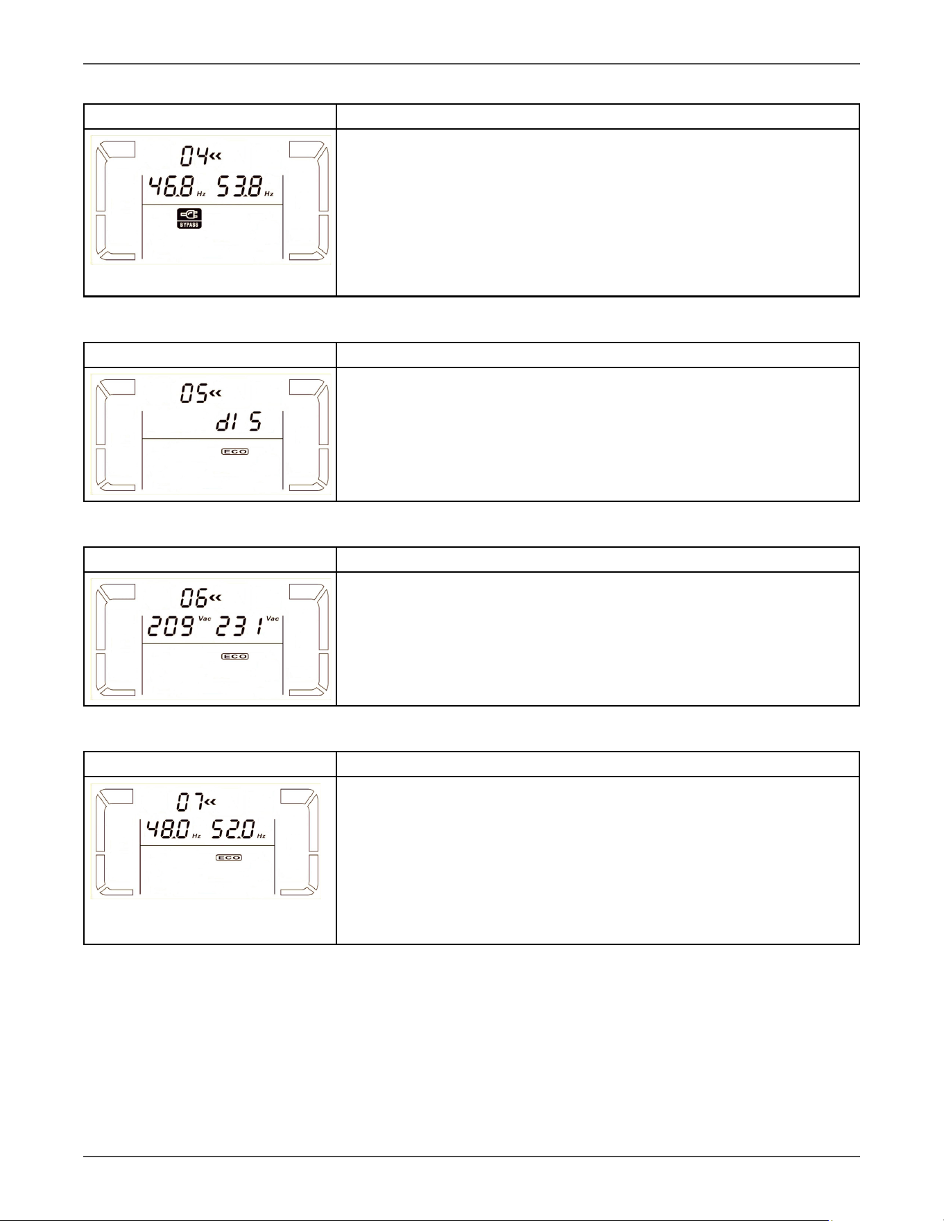
04: Frequency range for bypass
Interface Seng
Parameter 2: Set the acceptable low frequency for bypass.
50 Hz system: Seng range is from 46.0Hz to 49.0Hz.
60 Hz system: Seng range is from 56.0Hz to 59.0Hz.
The default value is 46.0Hz/56.0Hz.
Parameter 3: Set the acceptable high frequency for bypass.
50 Hz: Seng range is from 51.0Hz to 54.0 Hz.
60 Hz: Seng range is from 61.0Hz to 64.0Hz.
The default value is 54.0Hz/64.0Hz.
05: ECO mode enable/disable
Interface Seng
Parameter 3: Enable or disable ECO funcon. You may choose following
two opon:
DIS: disable ECO funcon
ENA: enable ECO funcon
If ECO funcon is disabled, voltage range and frequency range for ECO
mode sll can be set.
06: Voltage range for ECO mode
Interface Seng
Parameter 2: Low voltage point in ECO mode. The seng range is from 5%
to 10% of the nominal voltage.
Parameter 3: High voltage point in ECO mode. The seng range is from 5%
to 10% of the nominal voltage.
07: Frequency range for ECO mode
Interface Seng
Parameter 2: Set low frequency point for ECO mode.
50 Hz system: Seng range is from 46.0Hz to 48.0Hz.
60 Hz system: Seng range is from 56.0Hz to 58.0Hz.
The default value is 48.0Hz/58.0Hz.
Parameter 3: Set high frequency point for ECO mode.
50 Hz: Seng range is from 52.0Hz to 54.0 Hz.
60 Hz: Seng range is from 62.0Hz to 64.0Hz.
The default value is 52.0Hz/62.0Hz.
Xtreme Power Conversion Corporaon
TXVR 3.8- 10kVA User’s Manual
Page 21
Uninterrupble Power Supply
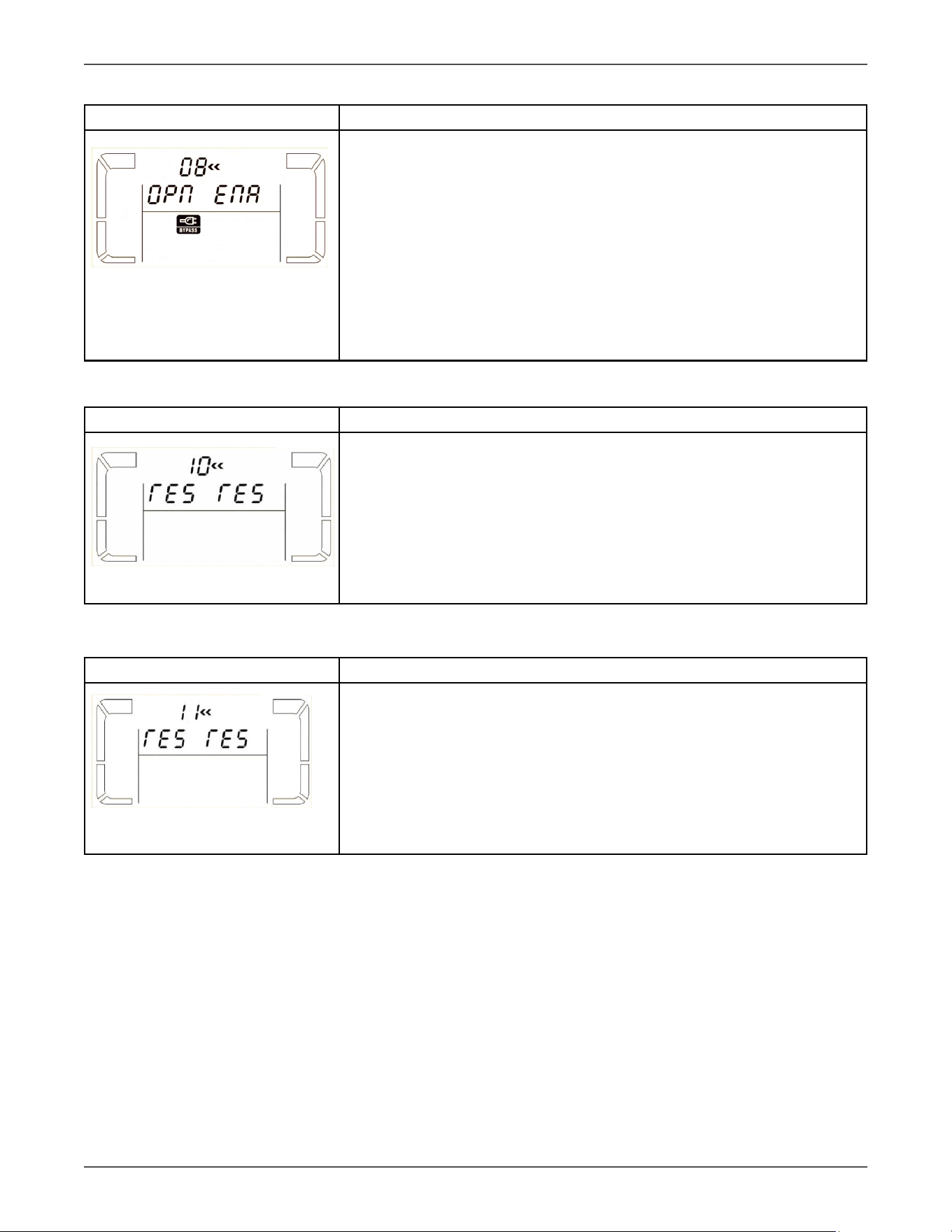
08: Bypass mode seng
Interface Seng
Parameter 2:
OPN: Bypass allowed. When selected, Voltage Regulator will run at Bypass
mode depending on bypass enabled/disabled seng.
FBD: Bypass not allowed. When selected, it’s not allowed for running in
Bypass mode under any situaons.
Parameter 3:
ENA: Bypass enabled. When selected, Bypass mode is acvated.
DIS: Bypass disabled. When selected, automac bypass is acceptable, but
manual bypass is not allowed. Manual bypass means users manually oper-
ate Voltage Regulator for Bypass mode. For example, pressing OFF buon
in AC mode to turn into Bypass mode.
9: Reserved
Interface Seng
Reserved
10: Reserved
Interface Seng
Reserved
Xtreme Power Conversion Corporaon
TXVR 3.8- 10kVA User’s Manual
Page 22
Uninterrupble Power Supply
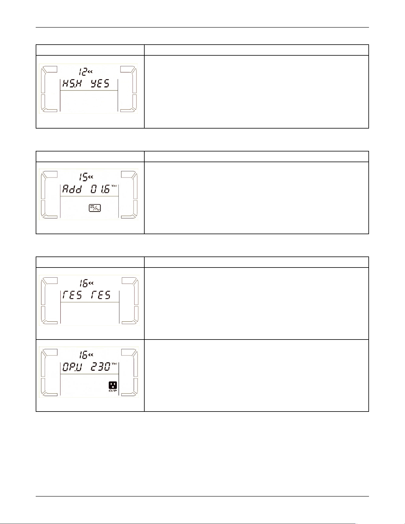
11: Hot standby funcon enable/disable
Interface Seng
Parameter 2: HS.H
Enable or disable Hot standby funcon. You may choose following two op-
ons in Parameter 3:
YES: Hot standby funcon is enabled. It means that the current Voltage
Regulator is set to host of the hot standby funcon, and it will restart aer
AC recovery even without baery connected.
NO: Hot standby funcon is disabled. The Voltage Regulator is running at
normal mode and can’t restart without baery
12: Inverter voltage adjustment
Interface Seng
Parameter 2: you may choose Add or Sub to adjust inverter voltage
Parameter 3: the voltage range is from 0V to 6.4V, the default value is 0V.
13: Output voltage calibraon
Interface Seng
When the output voltage can not be detected(less than 50VAC), “ ” will be
displayed in parameter 2 and parameter 3.
Parameter 2: it always shows OP.V as output voltage.
Parameter 3: it shows the internal measurement value of the output volt-
age, and you can calibrate it by pressing Up or Down according to the mea-
surement from an external voltage meter. The calibraon result will be ef-
fecve by pressing Enter. The calibraon range is limited within +/-9V.
Xtreme Power Conversion Corporaon
TXVR 3.8- 10kVA User’s Manual
Page 23
Uninterrupble Power Supply
4 Troubleshoong
If the Voltage Regulator system does not operate correctly, please solve the problem by using the table below.
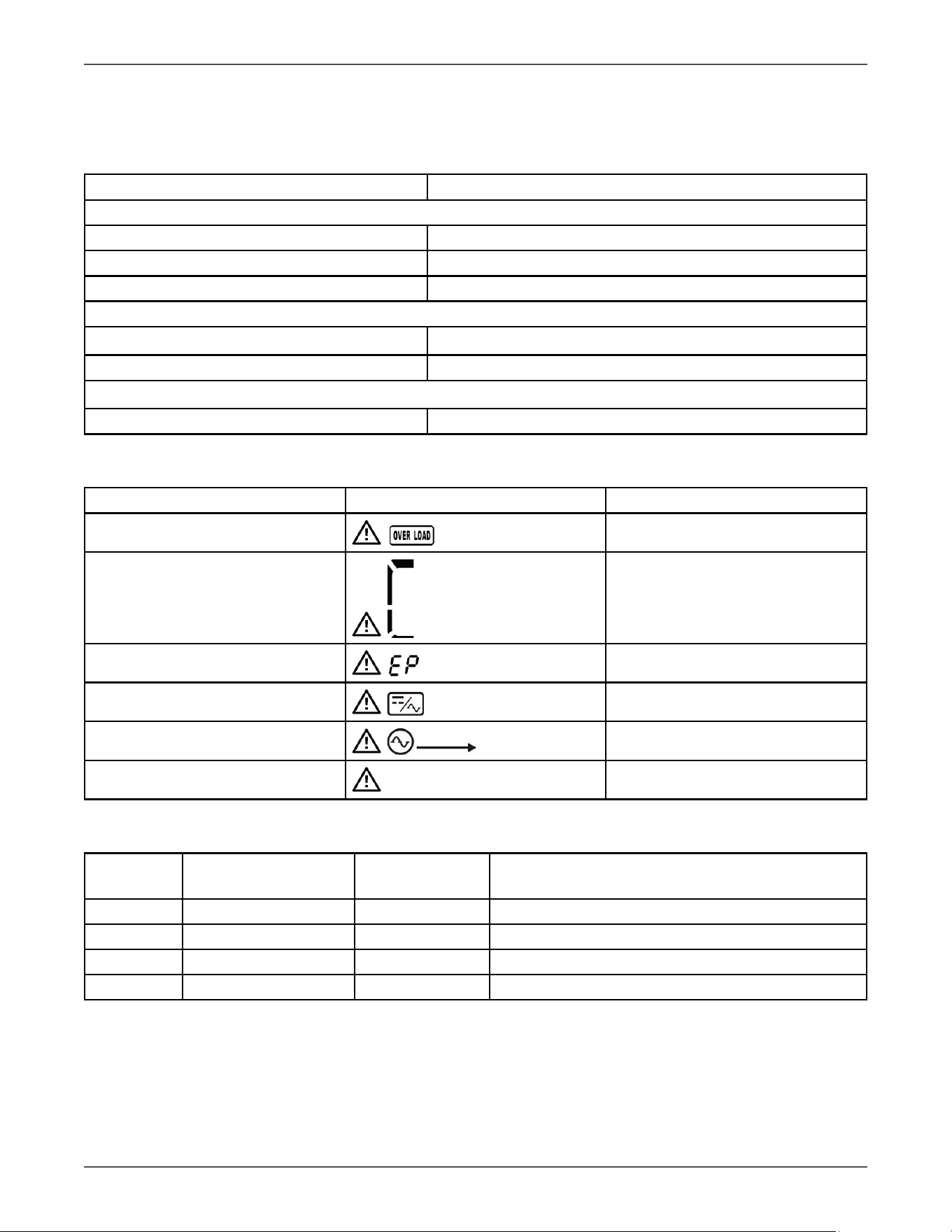
4.1 Audible Alarms
Descripon Buzzer status
Voltage Regulator status
Bypass mode Beeping once every 2 minutes
Baery mode Beeping once every 4 seconds
Fault mode Beeping connuously
Warning
Overload Beeping twice every second
Others Beeping once every second
Fault
All Beeping connuously
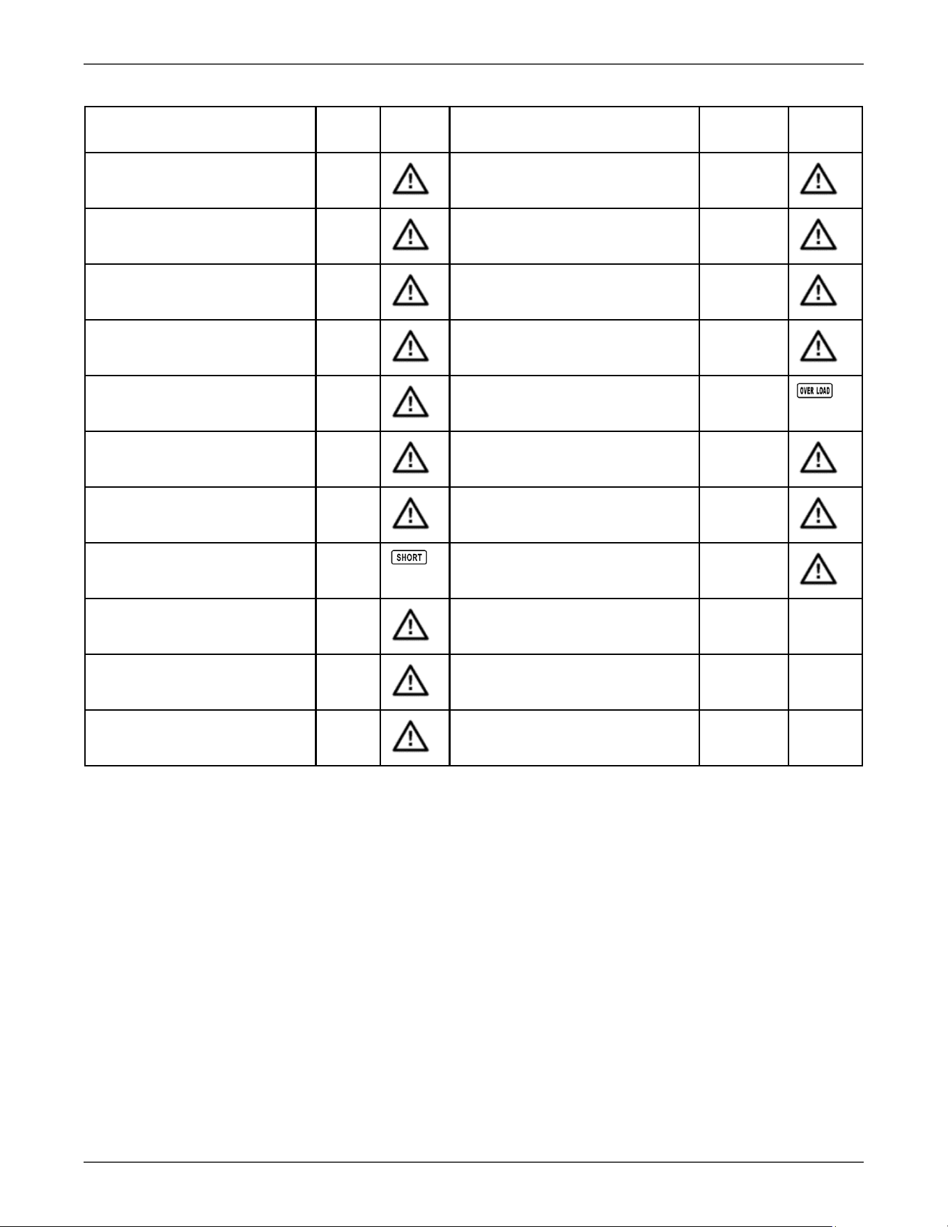
4.2 Warning Indicators
Warning Icon (ashing) Alarm
Overload
Beeping twice every second
Over charge
Beeping every second
EPO enable
Beeping every second
Fan failure/Over temperature
Beeping every second
I/P fuse broken
Beeping every second
Overload 3 mes in 30min Beeping every second
4.3 Warning Code Descripons
Warning
code
Warning event Warning code Warning event
0A Fan failure 3A Cover of maintain switch is open
0B
EPO enable
3D Bypass unstable
09
Overload
3E Boot loader is missing
10
L1 IP fuse broken
33 Locked in bypass aer overload 3 mes in 30 mins.
Xtreme Power Conversion Corporaon
TXVR 3.8- 10kVA User’s Manual
Page 24
Uninterrupble Power Supply
4.4 Fault Code Descripons
Fault event Fault
code
Icon Fault event Fault code Icon
Bus start failure 01 Inverter relay short circuited 24
Bus over 02 Can communicaon fault 31
Bus under 03 Over temperature 41
Bus unbalance 04 CPU communicaon failure 42
Inverter so start failure 11 Overload 43
High Inverter voltage 12 PFC current failure in baery
mode
6B
Low Inverter voltage 13 Bus voltage changes too fast 6C
Inverter output short circuited 14
SPS 12V abnormal 6E
Negave power fault 1A Inverter current detecon error 6D
Inverter over current 60 Transformer over temperature 77
Inverter waveform abnormal 63
Xtreme Power Conversion Corporaon
TXVR 3.8- 10kVA User’s Manual
Page 25
Uninterrupble Power Supply
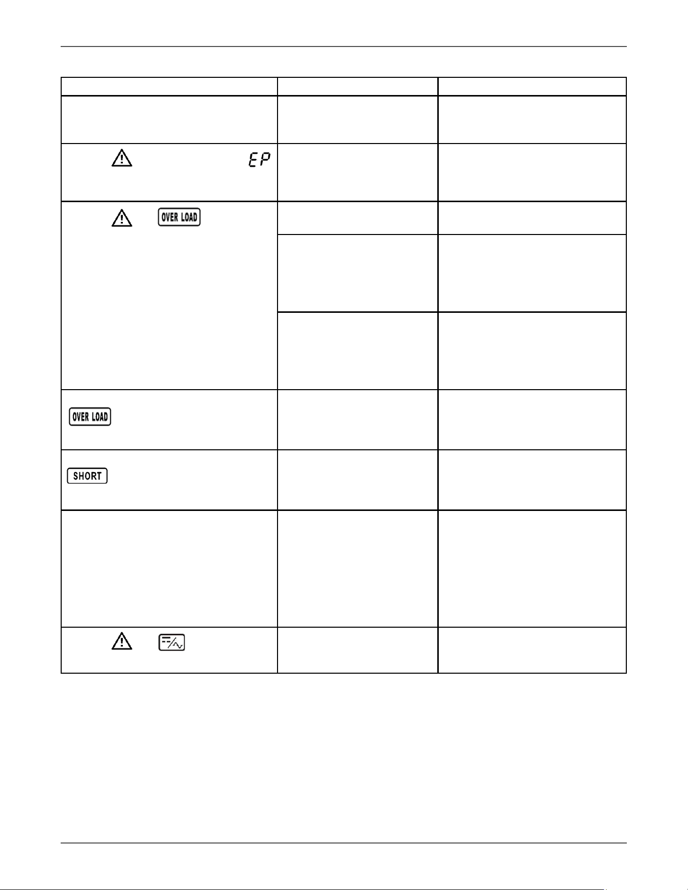
4.5 Trouble Shoong Chart
Symptom Possible cause Remedy
No indicaon and alarm in the front
display panel even though the mains is
normal.
The AC input power is not
connected well.
Check if input cable rmly con-
nected to the mains.
The icon and the warning code
ash on LCD display and alarm beeps
every second.
EPO funcon is enabled.
Set the circuit in closed posion to
disable EPO funcon.
The icon and ash on LCD
display and alarm beeps twice every
second.
Voltage Regulator is over-
loaded.
Remove excess loads from Voltage
Regulator output.
Voltage Regulator is over-
loaded. Devices connected
to the Voltage Regulator are
fed directly by the electrical
network via the Bypass.
Remove excess loads from Voltage
Regulator output.
Aer repeve overloads, the
Voltage Regulator is locked in
the Bypass mode. Connected
devices are fed directly by the
mains.
Remove excess loads from Voltage
Regulator output rst. Then shut
down the Voltage Regulator and
restart it.
Fault code is shown as 43. The icon
lights on LCD display and alarm
beeps connuously.
Voltage Regulator is overload
too long and becomes fault.
Then Voltage Regulator shut
down automacally.
Remove excess loads from Voltage
Regulator output and restart it.
Fault code is shown as 14, the icon
lights on LCD display, and alarm
beeps connuously.
The Voltage Regulator shut
down automacally because
short circuit occurs on the Volt-
age Regulator output.
Check output wiring and if con-
nected devices are in short circuit
status.
Fault code is shown as 01, 02, 03, 04, 11,
12, 13, 14,1A, 21, 24, 35, 36, 41, 42 or 43
on LCD display and alarm beeps connu-
ously.
A Voltage Regulator internal
fault has occurred. There are
two possible results:
1. The load is sll supplied,
but directly from AC power via
bypass.
2. The load is no longer sup-
plied by power.
Contact your dealer.
The icon and ash on LCD
display and alarm beeps every second.
Fan is locked or not working; or
the Voltage Regulator tempera-
ture is too high.
Check fans and nofy dealer.
Xtreme Power Conversion Corporaon
TXVR 3.8- 10kVA User’s Manual
Page 26
Uninterrupble Power Supply
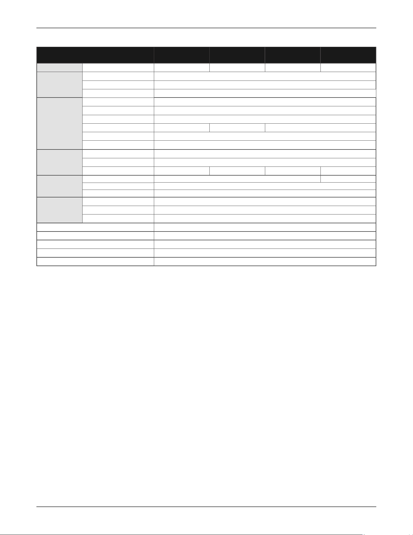
5 Specicaons
*6kVA system capacity will be reduced by 30A input circut
MODEL NUMBER
TXVR-3.8K TXVR-5K TXVR-6K TXVR-10K
CAPACITY
Power rang
3.8kVA/3.8kW 5kVA/5kW 6kVA/6kW 10kVA/10kW
INPUT
Voltage (nominal)
208/220/230/240VAC
Voltage range
110-300VAC
Frequency
46–54Hz or 56–64Hz
OUTPUT
Voltage
240/120VAC or 230/115VAC
Voltage Regulaon ± 1%
Frequency 50Hz ± 0.1Hz or 60 Hz ± 0.1Hz
Overload capacity
200% for 1 min 150% for 1 min 130% for 1 min
Eciency up to 97% ECO mode, 91% online mode
Harmonic Distoron
<2% @ 100% linear load (regardless of input distoron)
PHYSICAL
Input/output
Terminal blocks or oponal PDU
Dimensions (W x D x H) 9.8 x 23.2 x 32.4 in
Weight
142 lbs 145 lbs 148 lbs 187 lbs
OPTIONAL PDU
Input connecon
Terminal Block with 6 L6-30P* Terminal Block
120V receptacle opons
5-15/20R
240V receptacle opons
L6-30R, L6-20R, 6-15/20R, C19
ENVIRONMENT
Temperature
32–104°F (0–40°C)
Audible noise < 50dBA
Altude 11,500 above sea level
APPROVALS UL, cUL, RoHS
WARRANTY 3 years electronics (USA and Canada)
COMMUNICATIONS INTERFACE RS-232, EPO, intelligent slot for oponal cards (Web/SNMP, Relay/dry contact, Modbus)
INCLUDED IN BOX
User manual, RS-232 communicaon cable, ViewPower Soware CD
AVAILABLE OPTIONS 5 year extended warranty, output PDU, input L6-30P cord (for 3.8kVA, 5kVA, 6kVA)

Xtreme Power Conversion Corporaon
TXVR 3.8- 10kVA User’s Manual
Page 27
Uninterrupble Power Supply
6 Obtaining Service
If the UPS requires Service:
1. Use the TROUBLESHOOTING secon in this manual to eliminate obvious causes.
2. Verify there are no circuit breakers tripped.
3. Call your dealer for assistance. If you cannot reach your dealer, or if they cannot resolve the problem, call Xtreme
Power Conversion Corp Technical Support at 800.582.4524. Technical support inquiries can also be made at
[email protected]. Please have the following informaon available BEFORE calling the Technical Support
Department:
• Your name and address.
• The serial number of the unit.
• Where and when the unit was purchased.
• All of the model informaon about your Voltage Regulator.
• Any informaon on the failure, including LED’s that may or may not be illuminated.
• A descripon of the protected equipment, including model numbers if possible.
• A technician will ask you for the above informaon and, if possible, help solve your problem over the
phone. In the event that the unit requires factory service, the technician will issue you a Return Mate-
rial Authorizaon number (RMA).
If you are returning the UPS to Xtreme Power for service, please follow these procedures:
1. Pack the UPS in its original packaging. If the original packaging is no longer available, ask the Technical Sup-
port Technician about obtaining a replacement set of packaging material. It is important to pack the UPS
properly in order to avoid damage in transit. Never use Styrofoam beads for a packing material.
2. Include a leer with your name, address, dayme phone number, RMA number, a copy of your original
sales receipt, and a brief descripon of the problem.
3. Mark the RMA number on the outside of all packages. Xtreme Power cannot accept any package without
the RMA number marked on the outside of the boxes.
4. Return the UPS by insured, prepaid carrier to the address provided by the Technician.
5. Refer to the Warranty statements in this manual for addional details on what is covered.

Xtreme Power Conversion Corporaon
TXVR 3.8- 10kVA User’s Manual
Page 28
Uninterrupble Power Supply
7 Xtreme Power Conversion Limited Warranty
Xtreme Power Conversion (XPC) Corporaon warrants Xtreme Power Conversion equipment, when properly ap-
plied and operated within specied condions, against faulty materials or workmanship for a period of three years
for TXVR-Series products from the date of purchase. For equipment sites within the United States and Canada,
this warranty covers repair or replacement, at the sole discreon of XPC Corporaon. The customer is responsible
for the costs of shipping the defecve product to XPC Corporaon. XPC Corporaon will pay for ground shipment
of the repaired or replacement product. This warranty applies only to the original purchaser.
If equipment provided by XPC Corporaon is found to be Dead-on-Arrival (DOA), XPC Corporaon will be respon-
sible for the costs of shipping product to and returning equipment from the customer in a mely manner as agreed
to with the customer, once the customer has requested and received a Return Material Authorizaon (RMA)
number. DOA equipment is dened as equipment that does not properly funcon according to user documenta-
on when inially received and connected in conjuncon with proper procedures as shown in the user documen-
taon or via support provided by XPC Corporaon personnel or authorized agents.
This warranty shall be void if (a) the equipment is repaired or modied by anyone other than XPC Corporaon or
a XPC Corporaon approved third party; (b) the equipment is damaged by the customer, is improperly used or
stored, is subjected to an adverse operang environment, or is operated outside the limits of its electrical speci-
caons; or (c) the equipment has been used or stored in a manner contrary to the equipment’s operang manual,
intended use or other wrien instrucons. Any technical advice furnished by XPC Corporaon or a XPC Corpora-
on authorized representave before or aer delivery with regard to the use or applicaon of Xtreme Power Con-
version equipment is furnished on the basis that it represents XPC Corporaons best judgment under the situaon
and circumstances, but it is used at the recipient’s sole risk.
EXCEPT AS STATED ABOVE, XPC Corporaon DISCLAIMS ALL WARRANTIES, EXPRESSED OR IMPLIED, INCLUDING
WARRANTIES OF MERCHANTABILITY AND FITNESS FOR A PARTICULAR PURPOSE.
EXCEPT AS STATED ABOVE, IN NO EVENT WILL XPC Corporaon BE LIABLE FOR DIRECT, INDIRECT, SPECIAL, INCI-
DENTAL, OR CONSEQUENTIAL DAMAGES ARISING OUT OF THE USE OF Xtreme Power Conversion EQUIPMENT,
including but not limited to, any costs, lost prots or revenue, loss of equipment, loss of use of equipment, loss
of soware, loss of data, cost of substutes, or claims by third pares. Purchaser’s sole and exclusive remedy for
breach of any warranty, expressed or implied, concerning Xtreme Power Conversion equipment, and the only
obligaon of XPC Corporaon under this warranty, shall be the repair or replacement of defecve equipment,
components, or parts; or, at XPC Corporaons sole discreon, refund of the purchase price or substuon of an
equivalent replacement product.

Xtreme Power Conversion Corporaon
TXVR 3.8- 10kVA User’s Manual
Page 29
Uninterrupble Power Supply
8 Xtreme Power Conversion Load Protecon Policy
THIS POLICY IS NOT A WARRANTY. REFER TO THE XPC CORPORATION, INC. LIMITED WARRANTY FOR
INFORMATION CONCERNING THE WARRANTY FOR YOUR XPC PRODUCT. THE LIMITATIONS AND CONDITIONS
CONTAINED IN THIS POLICY DO NOT AFFECT THE TERMS OF THE XPC LIMITED WARRANTY.
Denions:
1. “Product” means a Standard 120, 208, or 240 Volt power protecon device that is used in the United
States and Canada. This policy does not include custom manufactured products.
2. “Power Disturbance” means an AC power line transient (telephone line or Local Area Network, if appli-
cable), spike or surge.
3. “Connected Equipment” properly connected electronic equipment
4. “Fair Market Value” of damaged Connected Equipment as determined by XPC shall be the lower of (a) the
average price the same or similar items are being sold for on eBay, (b) the price list of Orion Blue Book (or
if such price list is no longer published, a published or announced price list reasonably selected by XPC),
(c) the lowest price the same or similar items can be purchased for in the United States or (d) the total
amount of all payment(s) you have or are entled to receive from insurance, other warranes, extended
warranes, a legal liability claim or from other sources or persons for the damaged Connected Equipment.
5. “Purchaser” means the person or enty that originally purchased the Product from an authorized reseller
or distributor of XPC Products.
The Purchaser of this Product is protected, for the term of the XPC Limited Warranty, against certain losses caused
by a Power Disturbance for properly connected electronic equipment (referred to as the "Connected Equipment")
subject to certain terms and condions provided below.
This policy applies only to the original purchaser of the Product. If the Product is transferred or sold to another
person or enty, this policy is void.
Load Protecon Policy Dollar and Period Limits
For purchasers that meet the qualicaons and condions set forth in this policy, XPC will provide reimbursement
(cost of repair or fair market value as determined by XPC) during the period limits and up to the dollar limits stated
as follows:
PRODUCT DOLLAR LIMIT PERIOD OF COVERAGE
XVT, XST, S70 25,000 Term of XPC Limited Warranty
V80, P80, P80g, P90, P90L, P90g,
P90Lg, P91, T91, TX90, TX90i, TX91,
XPRT, TXVR
50,000
Term of XPC Limited Warranty
This Load Protecon Policy is not deemed "rst dollar" coverage. XPC’s obligaon is reduced by any amounts that
the Purchaser is entled to recover, from other sources regarding the Connected Equipment, including, but not
limited to, insurance, other warranty, extended warranty, or legal liability, regardless of whether or not the Pur-
chaser makes a claim for recovery.
Eligibility for Coverage Under the Load Protecon Policy
1. The Product must be registered on the XPC website, www.xpcc.com, within 10 days of purchase. All re-
quired informaon must be provided, and Purchaser should retain a copy for Purchaser’s records. When
registering on the website, Purchaser must list all connected equipment that is directly connected to the
product. Only those devices registered in that manner will be covered.
2. All Connected Equipment must be UL or CSA approved.
3. The Product must be plugged into a properly wired and grounded outlet. Use of input surge devices, ex-
tension cords, adapters, ground wires, or electrical connecons not manufactured by XPC voids the XPC
Load Protecon Policy. No other surge protecon device may be connected to the output sockets of the
Product. The installaon must comply with all applicable electrical and safety codes set forth pursuant to

Xtreme Power Conversion Corporaon
TXVR 3.8- 10kVA User’s Manual
Page 30
Uninterrupble Power Supply
the NEC.
4. The Product must have undeniable physical evidence of a Power Disturbance that directly and proximately
caused the damage;
5. The Connected Equipment must have been damaged by a Power Disturbance on a properly installed,
grounded, and Naonal Electric Code, ("NEC"), code-compliant 120, 208, 240 Volt AC power line in the
United States or Canada, by a Power Disturbance on standard telephone land line or PBX telephone equip-
ment line that is properly installed and connected to an RJ11 port on the Product; or by a Power Distur-
bance on a standard Local Area Network connecon that is properly installed and connected to an RJ45
port on the Product and (d) is directly plugged into, and properly connected to, the Product in its original
condion which was properly operated when a Power Disturbance passed through the Product and (i)
exhausts the protecon capacity of the Product or (ii) damages the Product.
6. The Load Protecon Policy does not apply if the Product has been operated in a failure mode or not in
compliance with XPC operang instrucons in the Product user's manual, or if the Connected Equipment
has not been operated in compliance with the instrucons and manuals of its manufacturer/vendor.
7. This policy is null and void if, XPC determines, in its sole discreon, that the Product has been tampered
with or altered in any way.
What is Not Covered Under the Load Protecon Policy:
The following damage is not covered by this Policy:
1. Restoraon of lost data and reinstallaon of soware.
2. Damage from a cause other than AC power-line transients, except for damage due to telephone line, Local
Area Network, or CATV transients, which is covered only if the Product oers such protecon.
3. DAMAGE CAUSED BY FAILURE TO PROVIDE A SUITABLE INSTALLATION ENVIRONMENT FOR THE PRODUCT
(INCLUDING, BUT NOT LIMITED TO, LACK OF A PROPER SAFETY GROUND).
4. Damage caused by the use of the Product for purposes other than those for which it was designed.
5. Damage caused by accidents, or natural disasters, including but not limited to, re, ood, and wind.
6. Damage caused by abuse, misuse, alteraon, modicaon, or negligence.
7. Any labor costs or travel, room and board expenses associated with the repair and/or restoraon of lost or
damaged hardware, soware or data.
EXCEPT AS EXPRESSLY PROVIDED IN THIS POLICY, XPC SHALL NOT BE LIABLE FOR ANY DAMAGES WHATSOEVER,
INCLUDING, BUT NOT LIMITED TO, DIRECT, INDIRECT, SPECIAL, INCIDENTAL, CONSEQUENTIAL, OR MULTIPLE
DAMAGES ARISING OUT OF THE USE OF THE PRODUCT OR DAMAGE TO THE CONNECTED EQUIPMENT, REGARD-
LESS OF THE LEGAL THEORY ON WHICH SUCH CLAIM IS BASED, EVEN IF ADVISED OF THE POSSIBILITY OF SUCH
DAMAGE. SUCH DAMAGES INCLUDE, BUT ARE NOT LIMITED TO, LOSS OF PROFITS, LOSS OF SAVINGS OR REV-
ENUE, LOSS OF USE OF THE PRODUCT OR THE CONNECTED EQUIPMENT OR ANY ASSOCIATED EQUIPMENT, LOSS
OF SOFTWARE, COST OF CAPITAL, COST OF ANY SUBSTITUTE EQUIPMENT, FACILITIES OR SERVICES, DOWNTIME,
THE CLAIMS OF THIRD PARTIES, INCLUDING CUSTOMERS, AND INJURY TO PROPERTY.
Subming a Load Protecon Policy Claim:
1. Any claim under the Load Protecon Policy must be made within 10 days of the date of alleged damage to the
Connected Equipment.
2. Call the XPC technical support department at 1-800- 582-4524 and obtain a Load Protecon Policy Returned
Material Authorizaon (RMA) number. Have informaon on all applicable insurance or other resources of re-
covery/payment that is available to the Purchaser and the name of the power ulity supplier for the locaon
of the Connected Equipment. XPC will forward to the Purchaser a Load Protecon Policy claims form, which
must be completed and led with XPC within 30 days.
• Mark the Load Protecon Policy RMA number on the Product the Purchaser is returning.
• Pack the Product in its original packaging or similar packing materials if the original packaging has
been discarded. Enclose the completed Load Protecon Policy claim form and a copy of the Purchas-
er’s original sales receipt for the Product in the box.
• Mark the RMA number clearly on the outside of the box.

Xtreme Power Conversion Corporaon
TXVR 3.8- 10kVA User’s Manual
Page 31
Uninterrupble Power Supply
• Ship the Product (one-way shipping charges paid by the Purchaser) to:
XPC Corporaon
230 Yuma Street
Denver, CO 80223
An: LPP RMA#
3. XPC will evaluate the Product to determine its level of funconality, and will examine the Product for evidence
of damage from a Power Disturbance.
• If XPCs' evaluaon provides no evidence of damage from a Power Disturbance, XPC will send to the
Purchaser (i) a report summarizing the tests performed and (ii) a rejecon of claim noce.
• If the Product shows evidence of damage from a Power Disturbance, XPC will request that all Con-
nected Equipment for which a Load Protecon Policy claim has been submied, be sent for evaluaon
to either XPC or an authorized service center. If it is determined that the Connected Equipment has
been damaged by a Power Disturbance, XPC will, in its sole discreon, issue payment to the Purchaser
for either the cost of repair of the Connected Equipment or the Fair Market Value of the damaged
Connected Equipment, up to the dollar limits stated above. XPC reserves the right to require the
Purchaser to transfer tle and deliver the Connected Equipment to XPC if it chooses to reimburse the
Purchaser for the fair market value of the Connected Equipment. XPCs' maximum liability shall be
reduced to reect all such other payments or sources of recovery, whether applied for or not.
4. If XPC issues payment to the Purchaser to have the Connected Equipment repaired, the repair must be per-
formed at a service center that is authorized by the manufacturer of the Connected Equipment. XPC reserves
the right to contact the authorized service center directly to discuss repair costs and damage to the Connected
Equipment to determine if it was caused by a Power Disturbance and the right to request that the service
center forward the Connected Equipment or components of the Connected Equipment to XPC for inspecon
5. Unless modied in wring signed by an ocer of XPC and the Purchaser, the terms of this policy are the com-
plete and exclusive agreement between the pares, superseding all prior agreements, oral or wrien, and all
other communicaons between the pares relang to the subject maer of this agreement. No employee of
XPC or any other party is authorized to make any representaons beyond those made in this agreement con-
cerning the Load Protecon Policy.
XPC Corporaon
230 Yuma Street
Denver, CO 80223
1.800.582.4524