OPERATOR'S
MANUAL
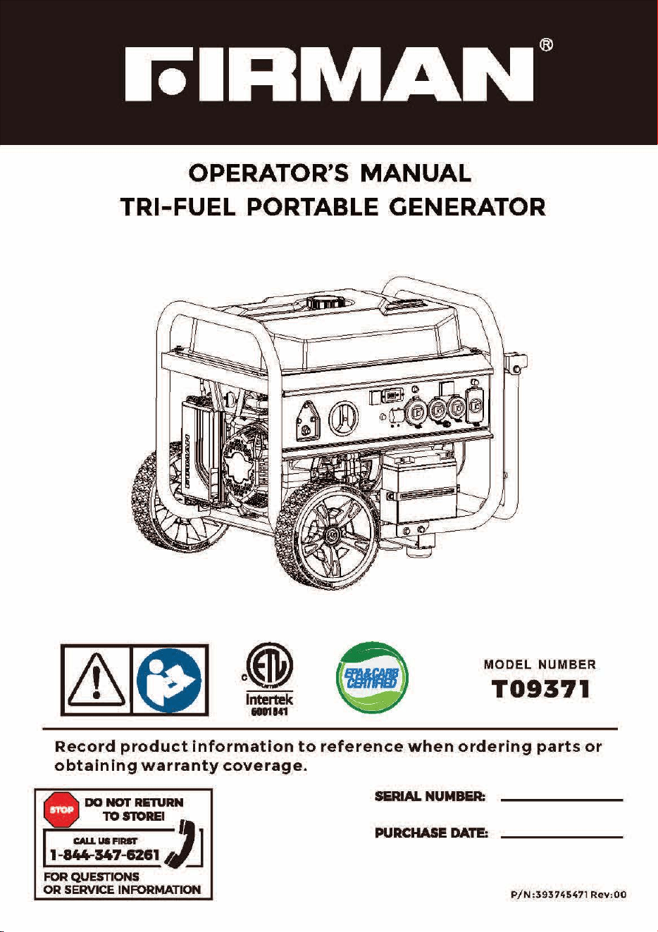
TRI-FUEL PORTABLE GENERATOR
MODEL
NUMBER
T09371
Record
product
information
to
reference
when
ordering
parts
or
obtaining
warranty
coverage.
DO
NOi'
AEl\lAN
• • •
lOSTOAEIJ
CAU.US,_
1-844-347--62&1
Ai
~
FOR QUESTIONS
OR
SERVICE INFORMATION
S&RIAL
NUM&R:
PURCHASE
DATE:
P/N:393745471Rev
:
OO
INTRODUCTION
Table
of
Contents
Introduction
......................................................................
1
Features
and
Controls
............................................................
5
Operation
.......................................................................
10
Maintenance
-
Storage
....................................
.
.....................
2 8
Troubleshooting-
Specifications
................................................
3 5
Parts
Diagrams
-
Parts
Lists
-Wiring
Diagram
....................................
37
Service
-
Warranty
..............................................................
43
[ REGISTER
YOUR
PRODUCT
J
Register
your
product
using
the
QR
code
provided
or
at
www.firmanpowerequipment.com.
INTRODUCTION
Thank
you
for
purchasing
a FIRMAN
generator.
You
have
selected
a
high-quality,
precision
engineered
generator
set
designed
and
tested
to
give
you
years
of
satisfactory
service.
This
generator
is
Tri-Fuel
and
capable
of
running
on
gasoline,
liquid
petroleum
gas
(LPG).
and
natural
gas
(NG). This
generator
is
not
intended
to
be
run
unattended
orto
supply
power
to
life
safety
support.
This
manual
contains
safety
information
to
make
you
aware
of
the
hazards
and
risks
associated
with
generator
products
and
how
to
avoid
them.
This
generator
is
designed
and
intended
only
for
supplying
electrical
power
for
operating
compatible
electrical
lighting,
appliances,
tools
and
motor
loads,
and
is
not
intended
for
any
other
purpose.
It
is
important
that
you
read
and
understand
these
instructions
thoroughly
before
attempting
to
start
or
operate
this
portable
generator.
Save
these
original
instructions
for
future
reference.
Al
I
information
in
th
is
publication
is
based
on
the
latest
p
reduction
information
available
at
the
time
of
approval
for
printing.
The
manufacturer
reserves
the
right
to
change,
alter
or
otherwise
improve
the
generator
and
this
documentation
at
any
time
without
prior
notice.
01
INTRODUCTION
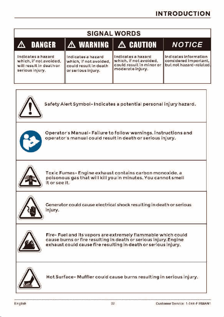
Indicates
a
hazard
which,
if
not
avoided,
will
result
in
death
or
serious
injury.
Indicates
a
hazard
which,
if
not
avoided,
could
result
in
death
or
serious
injury.
Indicates
a
hazard
which,
if
not
avoided,
could
result
in
minor
or
moderate
injury.
Indicates
information
considered
Important,
but
not
hazard-related
&
Safety
Ale,t
Symbol
-
Ind
iea
tes
,
pole
n ti al pees
on,
I i nj
u,y
hawd.
~
Operator
's
Manual-
Failure
to
follow
warnings.
instructions
and
operator
's
manua
I
could
result
in
death
or
serious
injury.
&
Toxic
Fumes-
Engine
exhaust
contains
carbon
monoxide,
a
poisono~s
gas
that
will
kill
you
in
minutes.
You
cannot
smell
1t
or
see
1t.
&
~':merator
could
cause
electrical
shock
resulting
in
death
or
serious
inJury.
£
Fire-
Fuel
and
its
vapors
are
extremely
flammable
which
could
cause
burns
or
fire
resulting
in
death
or
serious
injury.Engine
exhaust
could
cause
fire
resulting
in
death
or
serious
injury.
~
Hot
Surface-
Muffler
could
cause
burns
resulting
in
serious
injury.
English 02 Customer Service: 1 ·844· FIRMAN 1
INTRODUCTION
&
WARNING!
This
product
can
expose
you
to
chemicals
including
gasoline
engine
exhaust,
which
is
known
to
the
State
of
California
to
cause
cancer,
and
carbon
monoxide,
which
is
known
to
the
State
of
California
to
cause
birth
defects
or
other
reproductive
harm.
For
more
information
go
to
www.P65Warnings.ca.gov.
This
outdoor
generator
can
be
used
to
power
outdoor
items
using
extension
cords
or
to
restore
home
power
using
a
transfer
switch.
A
transfer
switch
is
a
separated
evice
installed
by
a
licensed
electrician
that
allows
the
portable
generator
to
be
cord
connected,
using
either
of
the
120/240V
receptacles,
directly
into
your
home's
electrical
system.
lnsta
II
a
listed
transfer
switch
as
soon
as
possible
if
th
is
generator
wil I
be
used
to
restore
power
to
your
home.
NOTICE
If
you
have
questions
about
intended
use,
contact
FIRMAN
customer
service.
This
portable
generator
is
designed
to
be
used
only
with
FIRMAN
authorized
parts.
System
Ground
The
generator
has
a
system
ground
that
connects
the
generator
frame
components
to
the
ground
terminals
on
the
AC
output
receptacles.
The
system
ground
is
connected
to
the
AC
neutral
wire.
The
neutral
is
bonded
to
the
generator
frame.
Compliance
Requirements
There
may
be
Federal
or
State
regulations,
local
codes,
or
ordinances
that
apply
to
the
intended
use
of
the
generator.
Consult
a
qualified
electrician,
electrical
inspector,
or
the
local
agency
having
jurisdiction.
This
generator
is
not
intended
to
be
used
at
a
construction
site
or
similar
activity
as
defined
by
N FPA
70-2020
(NEC)
section
590.6.
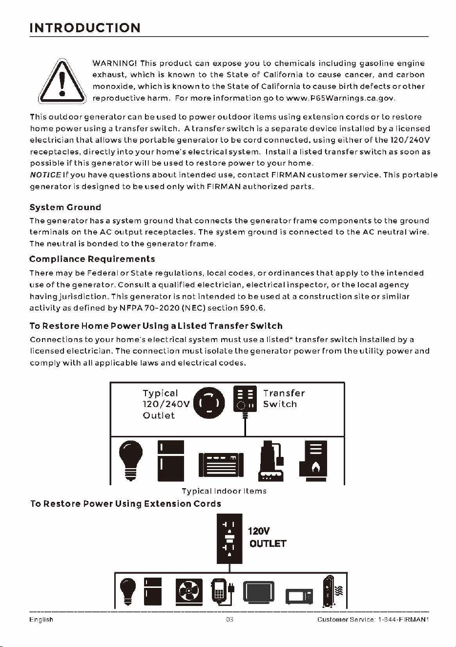
To
Restore
Home
Power
Using
a
Listed
Transfer
Switch
Connections
to
your
home's
electrical
system
must
use
a
listed*
transfer
switch
installed
by
a
licensed
electrician.
The
connection
must
isolate
the
generator
power
from
the
utility
power
and
comply
with
all
applicable
laws
and
electrical
codes
.
Typical
•
120/240V
Outlet
•
Transfer
Switch
f
Typical
Indoor
Items
To
Restore
Power
Using
Extension
Cords
English 03
120V
OUTLET
Customer
Service 1-844-FIRMAN1
INTRODUCTION
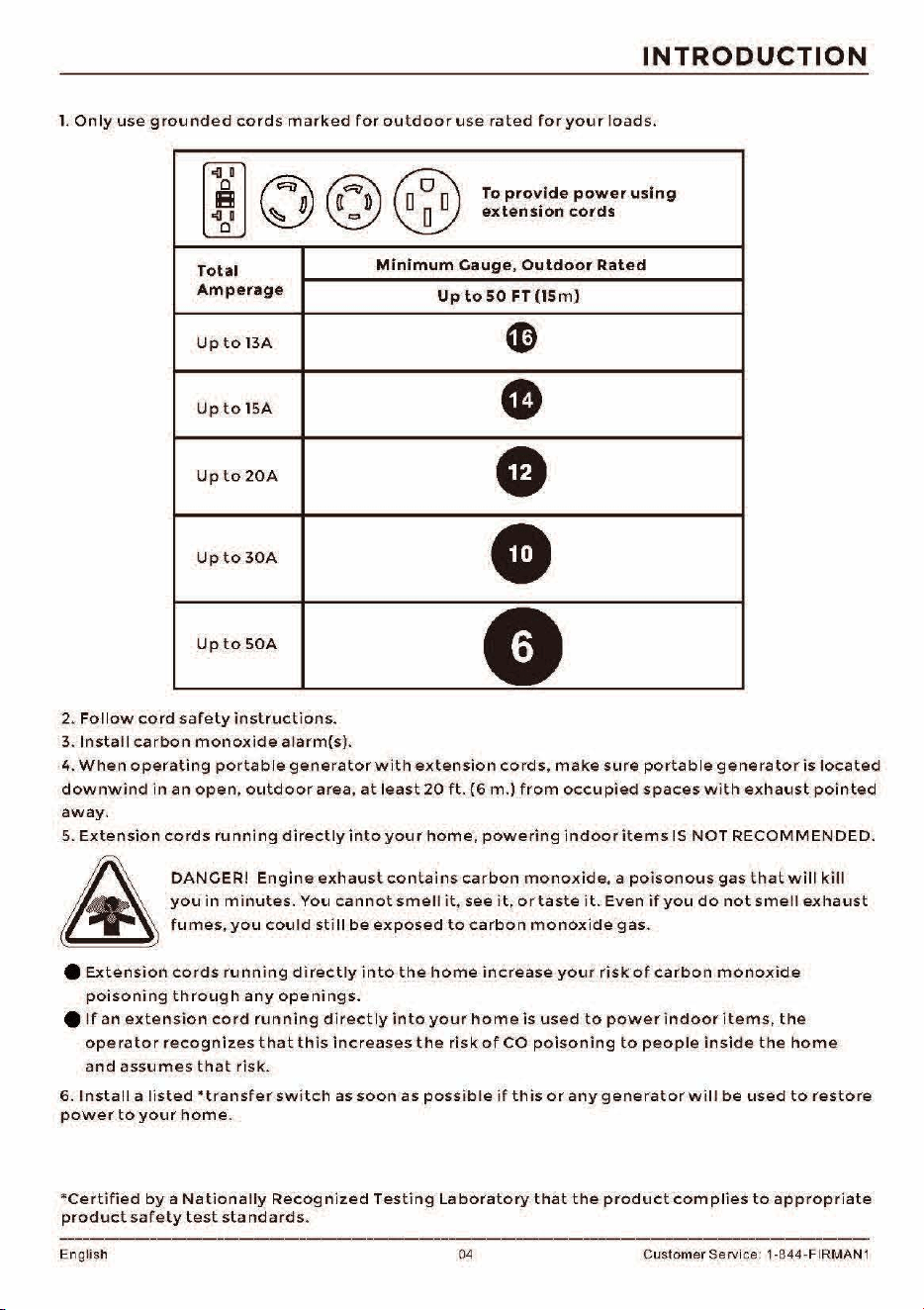
1.
Only
use
grounded
cords
marked
for
outdoor
use
rated
for
your
loads.
i
~@~
To
provide
power
using
extension
cords
0
I
Total
Minimum
Cauge,
Outdoor
Rated
Amperage
Up
to
so
FT
(15m)
Up
to
BA
~
Up
to
15A
-
Up
to
20A
•
Up
to
30A
•
Up
to
S0A
e
2.
Follow
cord
safety
instructions.
3.
Install
carbon
monoxide
alarm(s).
4.
When
operating
portable
generator
with
extension
cords,
make
sure
portable
generator
is
located
downwind
in
an
open,
outdoor
area,
at
least
20
ft.
(6
m.)
from
occupied
spaces
with
exhaust
pointed
away.
5.
Extension
cords
running
directly
into
your
home,
powering
indoor
items
IS
NOT
RECOMMENDED.
&
DANGER!
Engine
exhaust
contains
carbon
monoxide,
a
poisonous
gas
that
will
kill
you
in
minutes.
You
cannot
smell
it,
see
it,
or
taste
it.
Even
if
you
do
not
smell
exhaust
fumes,
you
could
still
be
exposed
to
carbon
monoxide
gas.
e
Extension
cords
running
directly
into
the
home
increase
your
risk
of
carbon
monoxide
poisoning
through
any
openings.
e
If
an
extension
cord
running
directly
into
your
home
is
used
to
power
indoor
items,
the
operator
recognizes
that
this
increases
the
risk
of
CO
poisoning
to
people
inside
the
home
and
assumes
that
risk.
6.
Install
a
listed
•transfer
switch
as
soon
as
possible
if
th
is
or
any
generator
will
be
used
to
restore
power
to
your
home.
*Certified
by
a
Nationally
Recognized
Testing
Laboratory
that
the
product
complies
to
appropriate
product
safety
test
standards.
English 04 Customer Service: 1-844-FIRMAN 1
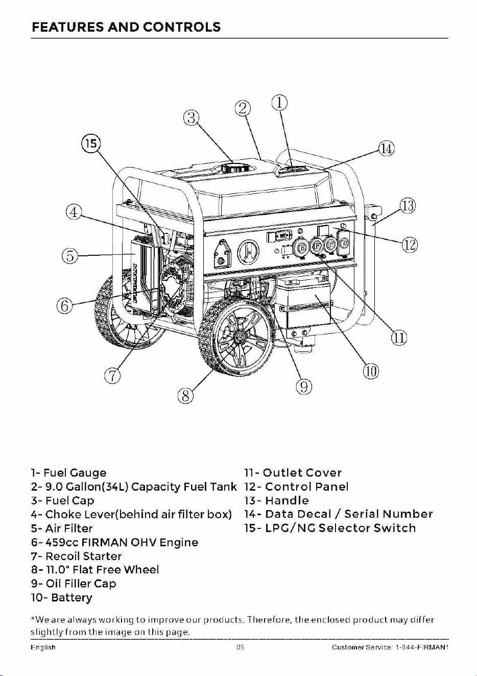
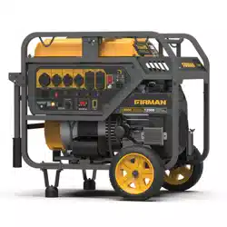
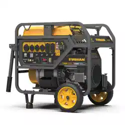
FEATURES
AND
CONTROLS
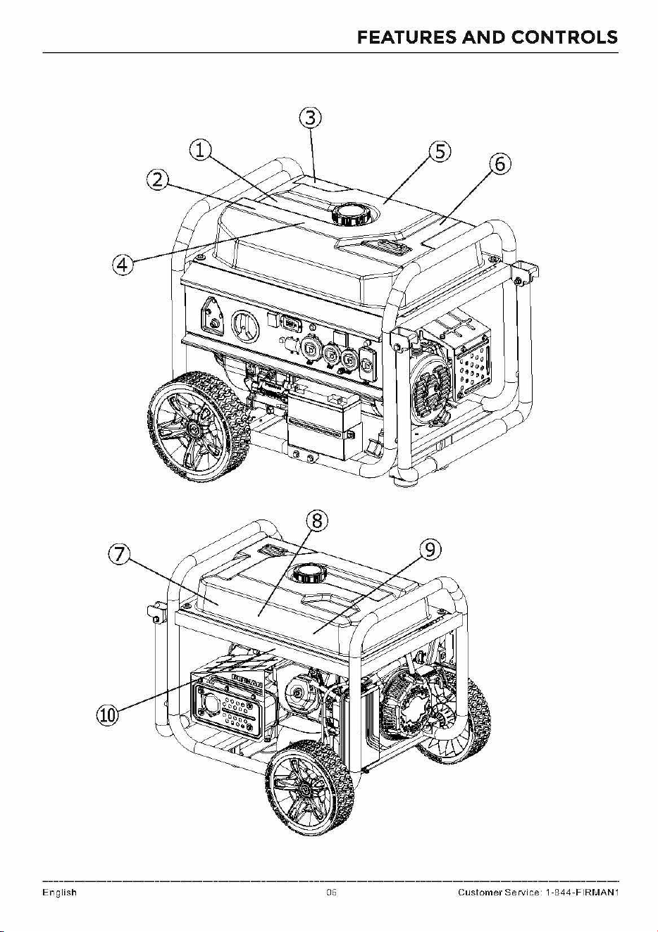
1- Fuel
Gauge
2-
9.0
Gallon{34L)
Capacity
Fuel
Tank
3-
Fuel
Cap
4-
Choke
Lever{behind
air
filter
box)
5-
Air
Filter
6-
459cc
FIRMAN
OHV
Engine
7-
Recoil
Starter
8-11.0"
Flat
Free
Wheel
9-
Oil
Filler
Cap
10-
Battery
11-
Outlet
Cover
12-
Control
Panel
13-
Handle
14-
Data
Decal/
Serial
Number
15-
LPG/NG
Selector
Switch
*We
are
always
working
to
improve
our
products.
Therefore,
the
enclosed
product
may
differ
slightly
from
the
image
on
this
page.
English 05
Customer
Service 1-844-FIRMAN1
FEATURES
AND
CONTROLS
English 06 Custo
me
r Service 1-844-FIRMA
N1
FEATURES
AND
CONTROLS
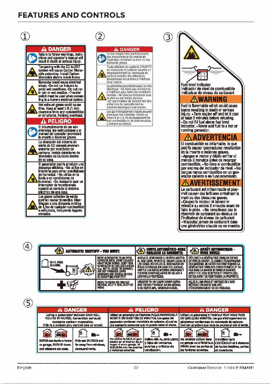
CD
Hot
must
guee
could
cau11&
11m.
Keep
at
1eut
5
ft.(1.5ml
clearance
from
any
combustibles
or
structure,,
lncl
u
lng
ovarhaad.
I.&
altenci6n
del
siSblma
de
£
alorta
de
ca
cauWlienvonon-
amianto
por
monOxido
de
carbano
.
lnstala
datectarm
d1
Mon6xido
de
c.a.rbona
dantro
dasu
casa.
:=~3~"':t~~fi
1
:eu~~
lnterio,..
para
ev!tar
condldones
&
dehumedad.
•Nouijllceen
la
lluvla
o
en
condlclones
de
humedad.
•Es
neDHil.rlD
usarun
l
ntenvplDr
de
transfilronda
cuando
sa
conecta
al
sistema
116cbico
de
una
casa.
Loo
geseo
callantlo
do
Sllkla
£
pod
nan
C111sar
lncendloo.
Mut-
tdnaase
a
una
dlstancla
min
i
ma
de
f
,5m
de
cualauler
combusll
ble
• o
estructura,
lncluyendo
lugan,s
elevados.
A DANGER
le
non•respect
des
avert
i
s$ements,
~
des
mslfuctiOns
et
du
manu
el
de.
r
oi>e
r
ateu
r
en
t
rarn
era
la
mon
ou
des
O!essur~
grpves
Toute
arttlratioo
du
syst
e
me
O'A
L
EATE
£
du
IJlono.xyde
de
ca
r
tione
ca.usera
un
~:~e
0
fnit~~~I:
~i
,
~xru~
de
demonoxy(le
de
cart>one
a
nnttlrieur
de
lamaison
La
gentrat
nte
pour
r
an
proYOquer
tin
choc
~t
ri
Que
. •
Na
laites
pas
f011ct1.ormer
&
i
nnterteur
oour
evifer
les
conditioos
hu
midts
. • Ne !
afle
s
pas
looctio
1me
r
soos
la.
plute
ou
pa
r
temps
pl\J
Vi
eu
.:
•
lJ1l
comrriutateur
de
traris!en
ao,1
&Ire
tJ
l
ihS6
l
orl
dti
raccordeme.nt
au
s,;st!ma
6k!Gtntlue
d
'une
maJson,
Les
gaz
a'6chappernen
t
cnauds
pewem
£
p<OW1que,
d
es
incend~.
Ga,dez
au
moms5
(1.Sm)o&~gementae
tout
co,t1
~usbble
ou
de
r
ou
te str
uctu1e,
y
compns
au~essos
.
Q)
u,rng • generator lndoon CAN
ICILL
YOU
IN
MINUTB.
Cien11,atm'axhauat
,:;iontalns
1;41rbon
monoxJd._
Thlt
r, a pollOll you
cannot'"
or tmelL
utltuir
11'1..,....
11\
lnterioNII
PUEDE
PROYOCMlA
MUERTE
EN
CUEST10N
DE
MINUR>S.
Lot~
di!
gwwradorconH•nan
rr,on6Xldo
de
arbono_,
el
cual
•
UM
llilltllle)I
vaneno.
que
no
puede
Wfff
~
o1,,_
En
gli
sh
NIEVEAwehlde1ho1M Ort,UNOIJnlDE1nd
or
911'19',
EVEN
IF
doot'I
fi
r
l'lltl1flom
wlndowlt
and.._
1r1
open.
doorunc:I
wnts.
07
-
Fuel
level
Indicator
lndicador
de
nivel
de
combustible
lndicata
ur
de
nivuau
de
carburant
&
WARNING
Fuel
is
fla
m
mable
which
cou
ld
cause
bums
resulting
in
death
or
serio
us
ln)ury.
•
Tum
engine
off
and
let
It
co
ol
at
least
2
minutes
before
refueling.
•
Do
not
flll
1uel
above
fuel
level
lndlca1Xlr
.
•Never
add
fuel
toa
hot
or
running
generator.
El
combustible
es
inflamable,
lo
que
podrfa
i:aum
quemaduras
rasuttantBs
en
la
muerte
o
leslones
graves.
•
Apaoue
el
motor
y
d6jelo
enfriar
al
menos
2
minutos
antes
de
recargar
combus!lble.
•
No
Ilene
el
combustible
por
encima
def
indicador
de
nivel.,
No
cargue
nunca
combustible
en
un
gen-
eraaor
calienta
o
en
funcionamiento.
I A
VERTISSEMENT
Le
carburant
IISt
inflammable
et
pou-
milt
causer
des
brDlures
entralnant
la
mort
ou
des
blessuras
Jraves.
~lza~
~~~~r2et~in=-~tde
faire
le
plain.
•
Ne
remplissez
pas
le
reservoir
de
carburant
atHlessus
de
l'indical9ur
de
nill8illJ
de
carburant.
•
N'ajoutez
jamais
de
carburant
dans
une
glnllllll'1ce
chaude
ou
en
marche.
Ulllt.r
un
~
• rlrtirleur
PE.UT
YOUS
1UEA
EN
QUELQUES
MINUT'ES.
L•
taz
d'iichl,..,,1nldu
g6n6rataur
eontkinnenld1.1
moni,aydt
df
aborw.
Ced
Ntwi
poftonqutVOUIM
powa
Nvofr
nf
~ -
Custom
er
Service 1-844-FIRMA
N1
@
(J)
®
English
FEATURES
AND
CONTROLS
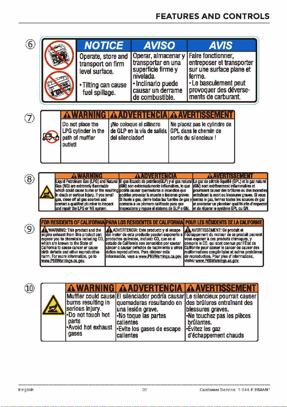
NOTICE AV/SO AVIS
Operate,
store
and
transport
on
firm
level
surface.
•
Tilting
can
cause
fuel
spillage.
Operar,
almacenar
y
transportar
en
una
superficie
firme
y
nivelada
.
•
lnclinarlo
puede
causar
un
derrame
de
combustible.
Faire
fonctionner,
entreposer
et
transporter
sur
une
surface
plane
et
ferme.
•
Le
basculement
peut
provoquer
des
deverse-
ments
de
carburant.
Do
not
place
the
r&l.
LP.
G
..
cylinder
in
the
iNO
coloque
el
cilindro
Ne
placez
pas
le
cylindre
de
~
path
of
muffler
outlet!
de
GLP
en
la
vra
de
salida
GPL
dans
le
chemin
de
del
silenciador!
sortie
du
si
lencieux
!
Gas
(NG)
are
li'Jdremety
flammable
(G
)
son
extremadamm
inflamables,
lo
que
(GN)
soot
extr!mement
inflammables
et
iell
cook!
call98
bums
or
fire
resutting
podrta
causar
quemaduras
o
inC81ldiOs
que
Po11nai8111
causer
des
broluree
ou
dee
incendi
In
death
or
se~ous
lnjllry.
tt
you
smell
podrtan
provocar
la
muerte
o
leslonee
graves.
entrarnant
la
mort
ou
blessuree
graves.
SI
vous
gas,
close
off
all
oas
sou
mes
and
Si
huele
a
oas,
cierre
todas
las
fuenles
de
gas
y
senb2
le
gaz,
fermez
tom
les
soumes
de
gaz
COll1aCI
a
qoalifiad
plumber
to
inspect
co111ac1u
un
plomero
califieado
para
qoe
at
conlaClllrun
plombier
qoalifihfin
d'inspeclll
811d
•
ehlstema
de
GLP
O
GN
.
at
de
e
GPI.
OU
GN.
11EIAl'ARIIE
ADVERTENCIA:
Este
producto
y
el
escape
AVERTISSEMENT:
C.
produh
at
engine
exhaust
from
tlliS
product
can
de
moior
de
este
prodlleto
pueden
expone~o
a
'6ct,appement
du
m0teur
de
ca
produil
peovent
expose
you
to
Cllemieals
including
CO,
prcdoctos
qofmicos,
incluido
CO,
queen
el
vous
exposer
l
des
prodoits
chimiqoes,
y
which
are
ktlown
to
the
State
Of
estado
de
califOmia
son
conocidos
por
causar
compris
le
co,
qui
sont
connus
par
l'ttat
de
CalHornla
to
cause
cancer
or
cause
ctncar
o
causar
defeclos
de
naclmlento
u
01ros
Calnornle
pour
causer
le
cancar
ou
ca
u
ser
des
birtll
defacfs
and
other
reproductive
da~os
reprodoctivos.
Para
obt8ner
mu
malformations
cong6nitales
at
aU1res
problllmes
harm.
For
more
infOnmation,
go
to
informaci6n,
vaya
a
www
.
P65Waminos.ca.gov.
de
reproduction.
Pour
plus
d'informations,
www
esswarn1oos
ca
gov
v1Slle2
www
esswam1ngs
ca
gov
M.uffle.
r
cou
.
Id
cause
E·.
I.
s
..
ilenc.ia.dor
pod
.
rfa
causar
Le•·
..
sile
.·
n.
cie.ux
pourra.
it
causer
burns
resulting
in
quemaduras
resultando
en
des
brOlures
entrainant
des
serious
injury.
una
lesi6n
grave.
blessures
graves.
·Do
not
touch
hot
•No
toque
las
partes
•Ne
touchei
pas
les
pieces
parts
calientes
brOlantes.
•Avoid
hot
exhaust
•Evite
los
gases
de
escape
•Evitez
les
gaz
gases
calientes
d'6chappement
chauds
08 Custo
mer
Service 1-
84
4-FIRM
A
N1
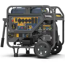
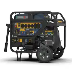
FEATURES
AND
CONTROLS
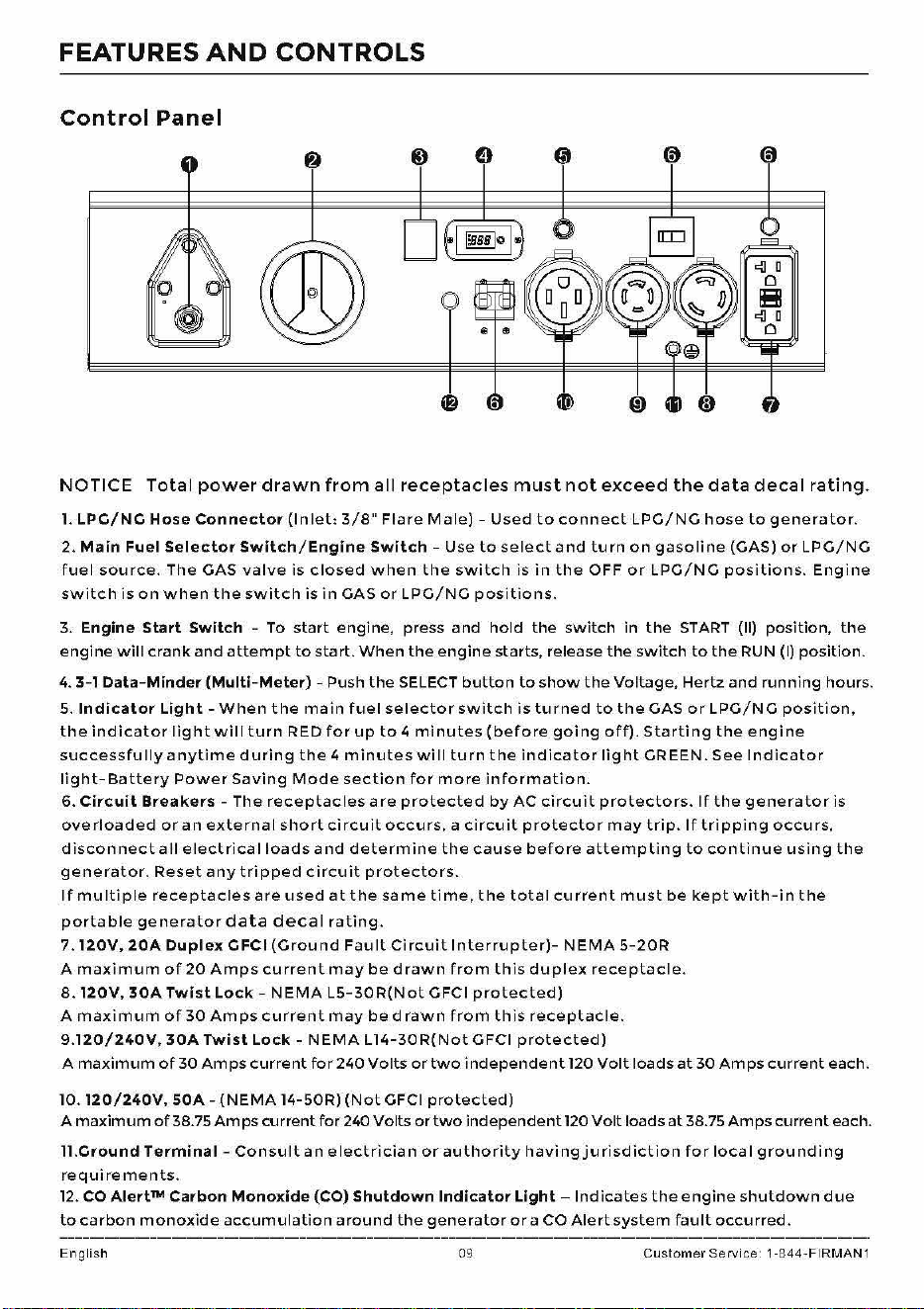
Control
Panel
NOTICE
Total
power drawn
from
all
receptacles
must
not
exceed
the
data
decal
rating.
l.
LPG/NG
Hose
Connector
(Inlet:
3/8"
Flare
Male)
-
Used
to
connect
LPG/NG
hose
to
generator.
2.
Main
Fuel
Selector
Switch/Engine
Switch
- Use
to
select
and
turn
on
gasoline
(GAS)
or
LPG/NG
fuel
source.
The GAS
valve
is
closed
when
the
switch
is
in
the
OFF
or
LPG/NG
positions.
Engine
switch
is
on
when
the
switch
is
in
GAS
or
LPG/NG
positions.
3.
Engine Start Switch - To
start
engine, press
and
hold
the
switch
in
the
START
(11)
position,
the
engine
will
crank
and
attempt
to
start.
When
the
engine
starts, release
the
switch
to
the
RUN (I)
position.
4.
3-1
Data-Minder
(Multi-Meter)
- Push
the
SELECT
button
to
show
the
Voltage,
Hertz
and
running
hours.
5.
Indicator
Light
-When
the
main
fuel
selector
switch
is
turned
to
the
GAS
or
LPG/NG
position,
the
indicator
light
wil
I
turn
RED
for
up
to
4
minutes
(before
going
off).
Starting
the
engine
successfully
anytime
during
the
4
minutes
wi
II
turn
the
indicator
light
GREEN.
See
Indicator
light-Battery
Power
Saving
Mode
section
for
more
information.
6.
Circuit
Breakers -
The
receptacles
are
protected
by
AC
circuit
protectors.
If
the
generator
is
overloaded
or
an
external
short
circuit
occurs,
a
circuit
protector
may
trip.
If
tripping
occurs,
disconnect
all
electrical
loads
and
determine
the
cause
before
attempting
to
continue
using
the
generator.
Reset
any
tripped
circuit
protectors.
If
multiple
receptacles
are
used
at
the
same
time,
the
total
current
must
be
kept
with-in
the
portable
generator
data
decal
rating.
7.
120V,
20A
Duplex
GFCI
(Ground
Fault
Circuit
Interrupter)-
NEMA
5-20R
A
maximum
of20
Amps
current
may
be
drawn
from
this
duplex
receptacle.
8.
120V,
30A
Twist
Lock -
NEMA
L5-30R(Not
GFCI
protected)
A
maximum
of
30
Amps
current
may
bed
rawn
from
this
receptacle.
9.120/240V,
30A
Twist
Lock
-
NEMA
L14-30R(Not
GFCI
protected)
A
maximum
of
30
Amps
current
for240Volts
or
two
independent
120
Volt
loads
at
30
Amps
current
each.
10.
120/240V,
S0A-
(NEMA
14-50R)
(Not
GFCI
protected)
A
maximum
of
38.75
Amps
current
for
240 Volts
or
two
independent
120
Volt
loads
at
38.75
Amps
current
each.
11.Ground
Terminal
-
Consult
an
electrician
or
authority
having
jurisdiction
for
loca
I
grounding
re
qui
re
men
ts.
12
.
CO
Alert™ Carbon Monoxide (CO)
Shutdown
Indicator
Light -
Indicates
the
engine
shutdown
due
to
carbon
monoxide
accumulation
around
the
generator
or
a CO
Alert
system
fault
occurred.
English 09 Custo
mer
Service 1-844-FIRMAN1
OPERATION
l.Location
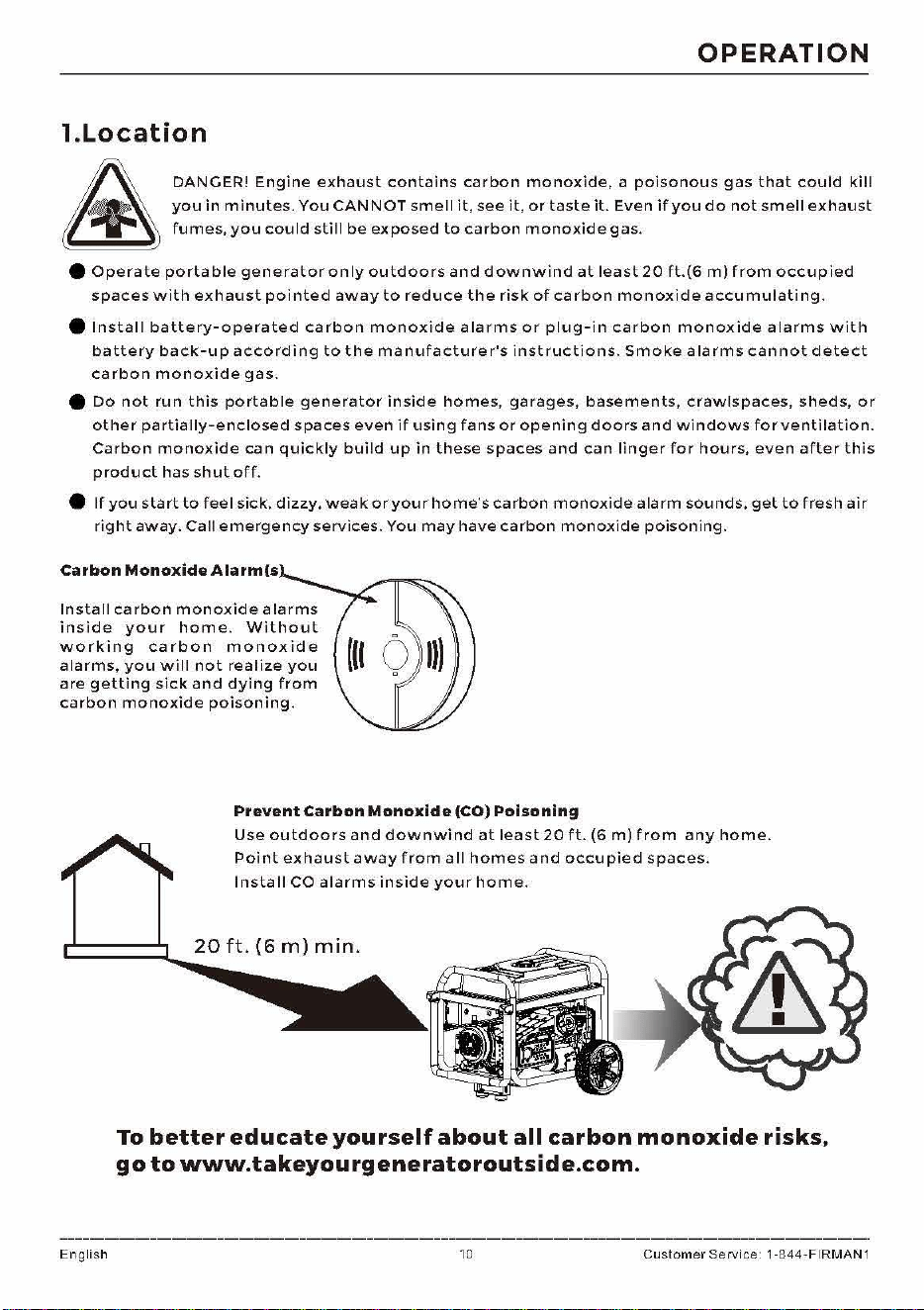
&
DANGER!
Engine
exhaust
contains
carbon
monoxide,
a
poisonous
gas
that
could
kill
you
in
minutes.
You
CANNOT
smell
it,
see
it,
or
taste
it.
Even
if
you
do
not
smell
exhaust
fumes,
you
could
still
be
exposed
to
carbon
monoxide
gas.
e
Operate
portable
generator
only
outdoors
and
downwind
at
least
20
ft.(6
m)
from
occupied
spaces
with
exhaust
pointed
away
to
reduce
the
risk
of
carbon
monoxide
accumulating.
e
Install
battery-operated
carbon
monoxide
alarms
or
plug-in
carbon
monoxide
alarms
with
battery
back-up
according
to
the
manufacturer's
instructions.
Smoke
alarms
cannot
detect
carbon
monoxide
gas.
e
Do
not
run
this
portable
generator
inside
homes,
garages,
basements,
crawlspaces,
sheds,
or
other
partially-enclosed
spaces
even
if
using
fans
or
opening
doors
and
windows
for
ventilation.
Carbon
monoxide
can
quickly
build
up
in
these
spaces
and
can
linger
for
hours,
even
after
this
product
has
shut
off.
e
If
you
start
to
feel
sick,
dizzy,
weak
or
your
home's
carbon
monoxide
alarm
sounds,
get
to
fresh
air
right
away.
Call
emergency
services.
You
may
have
carbon
monoxide
poisoning.
Carbon
Monoxide
Alarm(s
Install
carbon
monoxide
alarms
inside
your
home.
Without
working
carbon
monoxide
alarms,
you
will
not
realize
you
are
getting
sick
and
dying
from
carbon
monoxide
poisoning.
Prevent
Carbon
Monoxide
(CO)
Poisoning
Use
outdoors
and
downwind
at
least
20
ft.
(6
m)
from
any
home.
Point
exhaust
away
from
all
homes
and
occupied
spaces.
English
Install
CO
alarms
inside
your
home.
To
better
educate
you
rs
elf
about
all
carbon
monoxide
risks,
go
to
www.takeyourgeneratoroutside.com.
10
Customer
Service 1-844-FIRMAN1
OPERATION
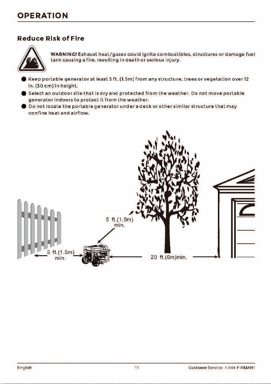
Reduce
Risk
of
Fire
h..
WARN
INC!
Exhaust
heat/gases
could
ignite
combustibles,
structures
or
damage
fuel
~
tank
causing
a
fire,
resulting
in
death
or
serious
injury.
e
Keep
portable
generator
at
least
5
ft.
(l.Sm)
from
any
structure,
trees
or
vegetation
over
12
in
.
(30
cm)
in
height.
e
Select
an
outdoor
site
that
is
dry
and
protected
from
the
weather.
Do
not
move
portable
generator
indoors
to
protect
it
from
the
weather.
e
Do
not
locate
the
portable
generator
under
ad
eek
or
other
similar
structure
that
may
confine
heat
and
airflow.
English
\
,
11
..,,
~
5 ft.{1 .5m)
min.
/
_s
ft.{1.5m)
-Q~
min
........
.
_..,.,._IKJa""t
,.,
____
_
11
I
..
\c
~
..
20
ft
.{6m)min.
Customer Service: 1-844-FIRMAN 1
2.
Oil
and
Gasoline/
LPG/
NC
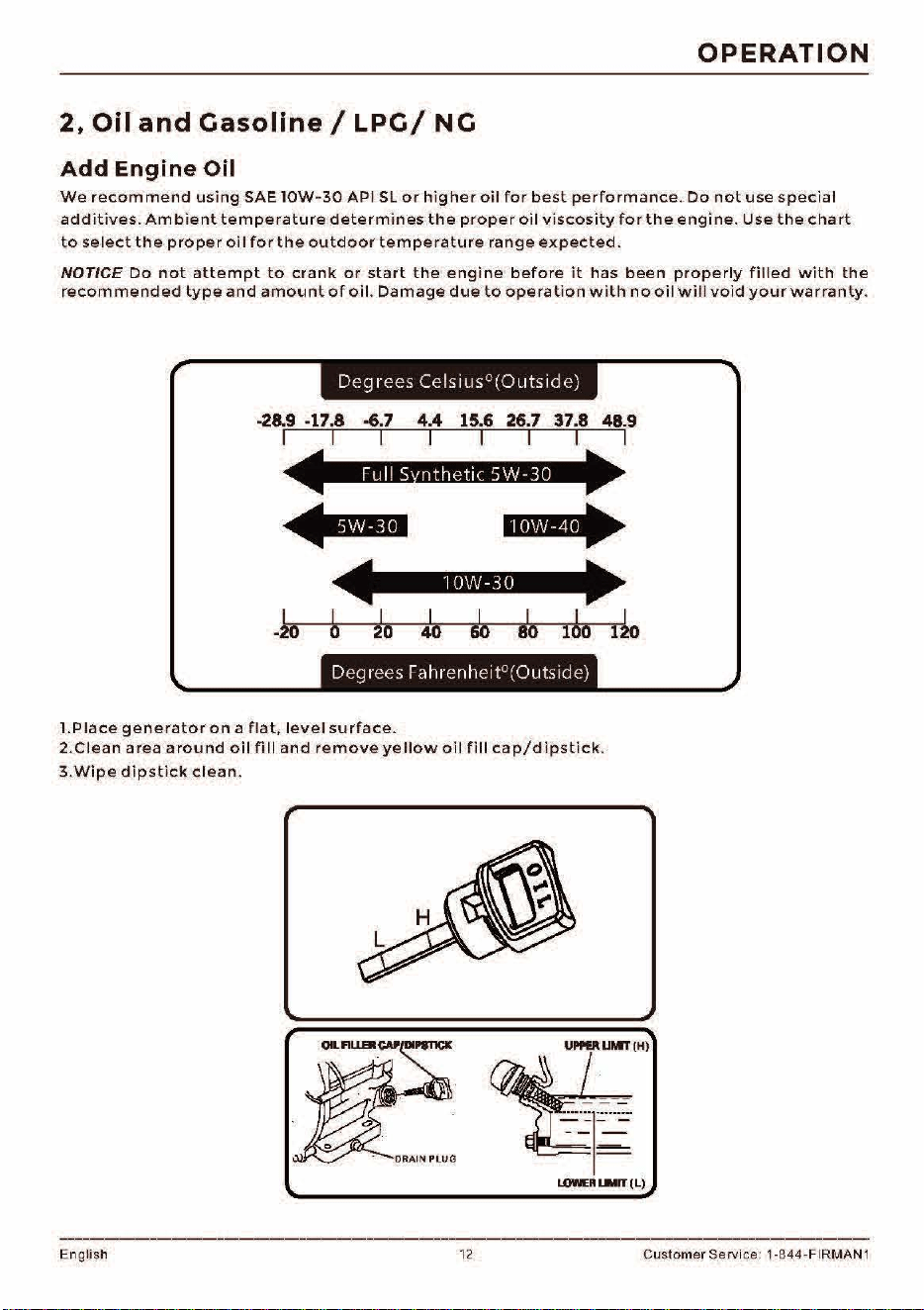
Add
Engine
Oil
OPERATION
We
recommend
using
SAE
lOW
-
30
API
SL
or
higher
oil
for
best
performance.
Do
not
use
special
additives.
Ambient
temperature
determines
the
proper
oil
viscosity
for
the
engine.
Use
the
cha
rt
to
select
the
proper
oil
for
the
outdoor
temperature
range
expected.
NOTICE
Do
not
attempt
to
crank
or
start
the
engine
before
it
has
been
properly
filled
with
the
recommended
type
and
amount
of
oil
.
Damage
due
to
operation
with
no
oil
wi
ll
void
your
warranty
.
Deg
r
ees
Cels
1
us
0
(0
ut
s1
de)
-6.7
I
20
4.4
15.6
26
.7 37.8 48.9
I I I I I
l•lU'M•
I I
100 120
D
eg
1ees
ra
h
re
nh
c1t
0
(0
uts1de)
I.Place
generator
on
a
flat,
level
surface.
2.Clean
area
around
oil
fill
and
remove
yellow
oil
fill
cap/dipstick.
3.Wipe
dipstick
clean.
~11.MT(H
)
~l~
LOWElll..lllfT(L)
English
12
Customer Servi
ce
: 1-844-FIRMAN 1
OPERATION
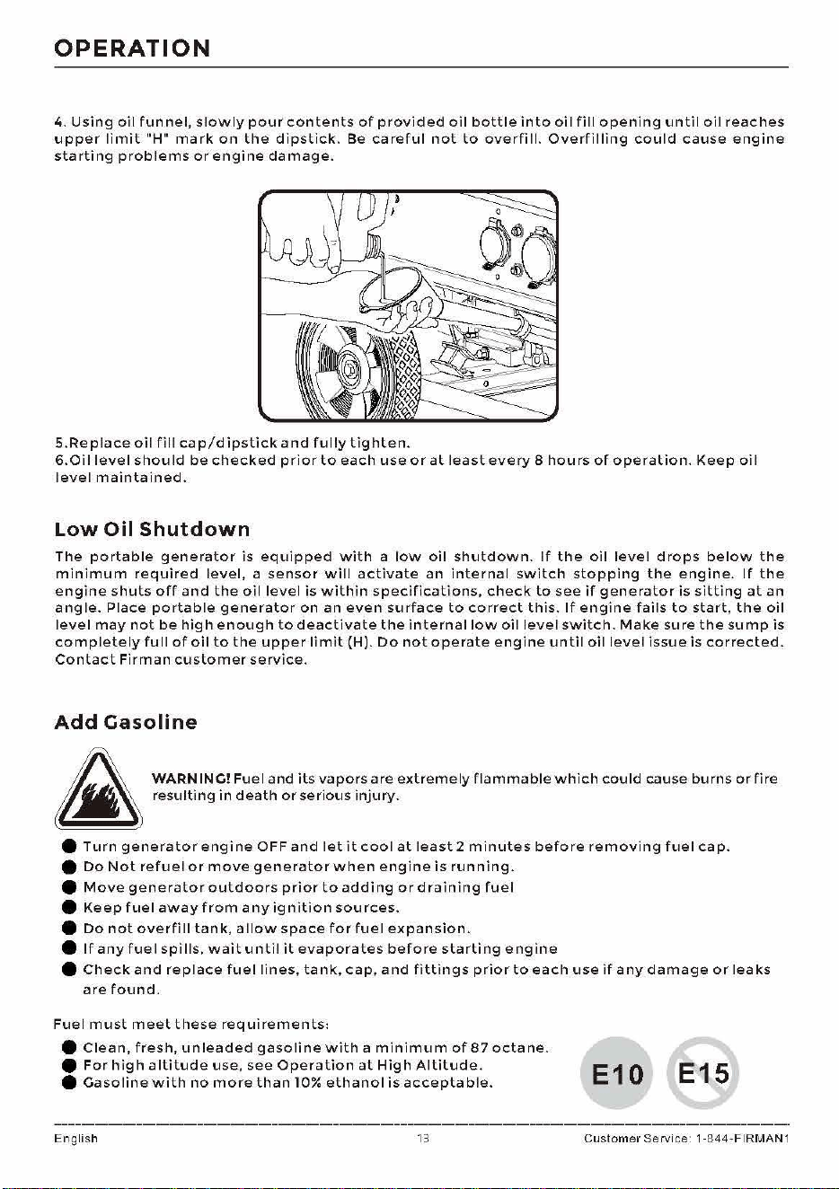
4.
Using
oil
funnel,
slowly
pour
contents
of
provided
oil
bottle
into
oil
fill
opening
until
oil
reaches
upper
limit
"H"
mark
on
the
dipstick.
Be
careful
not
to
overfill.
Overfilling
could
cause
engine
starting
problems
or
engine
damage.
5.Re
place
oil
fill
cap/dipstick
and
fully
tighten.
6.Oi
I
level
shou
Id
be
checked
prior
to
each
use
or
at
least
every
8
hours
of
operation.
Keep
oi
I
level
maintained.
Low
Oil
Shutdown
The
portable
generator
is
equipped
with
a
low
oil
shutdown.
If
the
oil
level
drops
below
the
minimum
required
level,
a
sensor
will
activate
an
internal
switch
stopping
the
engine.
If
the
engine
shuts
off
and
the
oil
level
is
within
specifications,
check
to
see
if
generator
is
sitting
at
an
angle.
Place
portable
generator
on
an
even
surface
to
correct
this.
If
engine
fails
to
start,
the
oil
level
may
not
be
high
enough
to
deactivate
the
internal
low
oil
level
switch.
Make
sure
the
sump
is
completely
full
of
oil
to
the
upper
limit
(H).
Do
not
operate
engine
until
oil
level
issue
is
corrected.
Contact
Firman
customer
service.
Add
Gasoline
:fi..
WARN INC! Fuel
and
its
vapors
are
extremely
flammable
which
could
cause
burns
or
fire
~
resulting
in
death
or
serious
injury.
e
Turn
generator
engine
OFF
and
let
it
cool
at
least
2
minutes
before
removing
fuel
cap.
e
Do
Not
refuel
or
move
generator
when
engine
is
running.
e
Move
generator
outdoors
prior
to
adding
or
draining
fuel
e
Keep
fuel
away
from
any
ignition
sources.
e
Do
not
overfill
tank,
allow
space
for
fuel
expansion.
e
If
any
fuel
spills,
wait
until
it
evaporates
before
starting
engine
e
Check
and
replace
fuel
lines,
tank,
cap,
and
fittings
prior
to
each
use
if
any
damage
or
leaks
are
found.
Fuel
must
meet
these
requirements:
e
Clean,
fresh,
unleaded
gasoline
with
a
minimum
of
87
octane.
e
For
high
altitude
use,
see
Operation
at
High
Altitude.
e
Gasoline
with
no
more
than
10%
ethanol
is
acceptable.
English 13
E10
E15
Customer
Service 1-844-FIRMAN1
OPERATION
NOTICE
Do
not
mix
oil
in
gasoline
or
modify
engine
to
run
on
alternate
fuels
not
described
in
this
manual.
Use
of
unapproved
fuels
could
damage
engine
and
will
not
be
covered
under
warranty.
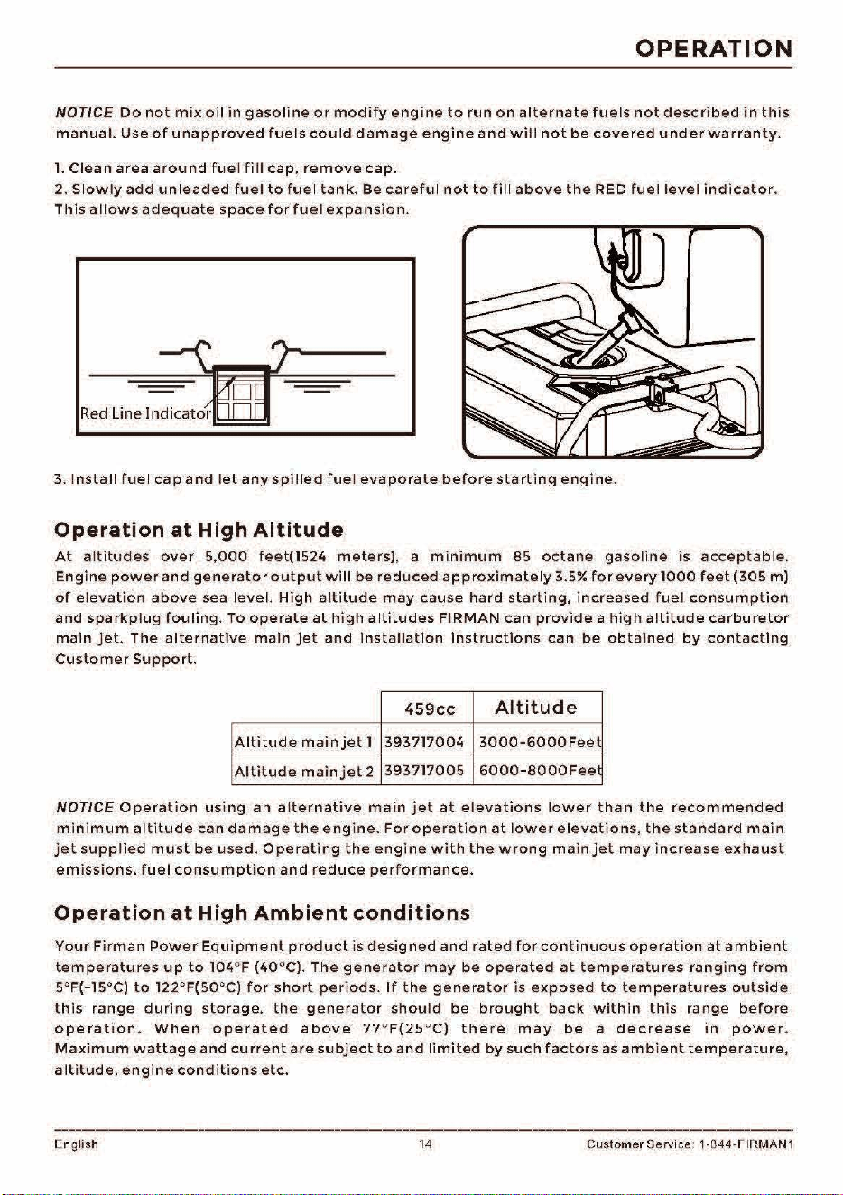
1.
Clean
area
around
fuel
fill
cap,
remove
cap.
2.
Slowly
add
unleaded
fuel
to
fuel
tank.
Be
careful
not
to
fill
above
the
RED
fuel
level
indicator.
This
allows
adequate
space
for
fuel
expansion.
3.
Install
fuel
cap
and
let
any
spilled
fuel
evaporate
before
starting
engine.
Operation
at
High
Altitude
At
altitudes
over
5,000
feet(1524
meters),
a
min,mum
85
octane
gasoline
is
acceptable.
Engine
power
and
generator
output
will
be
reduced
approximately
3.5¾
for
every
1000
feet
(305
m)
of
elevation
above
sea
level.
High
altitude
may
cause
hard
starting,
increased
fuel
consumption
and
sparkplug
fouling.
To
operate
at
high
altitudes
FIRMAN
can
provide
a
high
altitude
carburetor
main
jet.
The
alternative
main
jet
and
installation
instructions
can
be
obtained
by
contacting
Customer
Support.
459cc
Altitude
Altitude
main
jet
1
393717004
3000-6000Fee1
Altitude
main
jet
2
393717005
6000-S000Fee
NOTICE
Operation
using
an
alternative
main
jet
at
elevations
lower
than
the
recommended
minimum
altitude
can
damage
the
engine.
For
operation
at
lower
elevations,
the
standard
main
jet
supplied
must
be
used.
Operating
the
engine
with
the
wrong
main
jet
may
increase
exhaust
emissions,
fuel
consumption
and
reduce
performance.
Operation
at
High
Ambient
conditions
Your
Firman
Power
Equipment
product
is
designed
and
rated
for
continuous
operation
at
ambient
temperatures
up
to
104°F
(40
°C).
The
generator
may
be
operated
at
temperatures
ranging
from
5°F(-15°C)
to
122°F(50°C)
for
short
periods.
If
the
generator
is
exposed
to
temperatures
outside
this
range
during
storage,
the
generator
should
be
brought
back
within
this
range
before
operation.
When
operated
above
77
°
F(25
°C)
there
may
be
a
decrease
in
power.
Maximum
wattage
and
current
are
subject
to
and
limited
by
such
factors
as
ambient
temperature,
altitude,
engine
conditions
etc.
English
14
Customer Service: 1-844-FIRMAN 1
OPERATION
Connecting
LPG/
NG
Fuel
~
WARNING!
Liquid
Petroleum
gas
(LPG)
and
Natural
Gas (NG)
are
extremely
flammable
which
could
cause
burns
or
fire
resulting
in
death
or
serious
injury.
e
The
fuel
supply
line
must
always
be
shut
off
when
the
engine
is
not
running.
Failure
to
shut
off
fuel
may
allow
fuel
to
leak
at
the
generator.
e
Do
not
place
the
LPG/NG
sources
in
the
path
of
muffler
outlet
or
near
any
ignition
source.
e
Keep
a
fire
extinguisher
near
the
generator
all
the
time.
e
Do
not
use
or
store
LPG/NG
portable
sources
not
in
use
near
generator
or
in
a
building,
garage
or
enclosed
area.
e
All
LPG/NG
supply/
piping
lines
must
be
installed
bya
qualified
plumber.
e
If
you
smell
gas,
close
off
a
II
gas
sources
and
contact
a
qualified
plumber
to
inspect
and
repair
the
LPG
or
NG
system.
Prior
to
each
days
first
use
spray
a
soapy
water
solution
on
LPG/NG
fuel
connections
to
check
for
leaks.
e
Never
use
a
gas
container,
LPG/
NG
connector
hose,
LPG
cylinder
or
NG
source
that
appears
to
be
damaged.
e
Do
not
connect
or
disconnect
the
LPG/
NG
source
in
an
enclosed
area.
e LPG
is
heavier
than
air
and
can
accumulate
in
confined
/
low
spaces
if
there
is
a
leak.
NOTICE
If
a
fuel
supply
connection
is
necessary
it
must
be
installed
in
accordance
with
all
local
codes
or
regulations,
or
in
the
absence
of
local
codes
or
regulations,
in
accordance
with
the
National
Fuel
Gas
Code
(NFPA
54/ANSI
Z223.1)
and
CSA
B149.1
(Natural
Gas
and
Propane
Installation
Code).
as
applicable.
If
possible
the
fuel
supply
connection
should
be
close
to
the
outdoor
operating
location.
This
will
reduce
the
cost
of
the
flexible
fuel
run.
An
approved
flexible
fuel
line
must
be
installed
between
the
generator
LPG/NG
Hose
Connector
(Inlet)
and
the
fuel
supply
connection.
In
no
case
should
this
information
be
interpreted
to
conflict
with
any
local,
state,
or
national
code.
If
in
doubt,
always
follow
local
codes.
e
Always
keep
the
LPG
cylinder
in
an
upright
position.
e
Use
only
DOT LPG
cylinders
in
vapor
service
with
type
1,
right
hand
ACME
threads.
Verify
the
re-qualification
date
on
the
cylinder
has
not
expired.
e
All
new
cylinders
must
be
purged
of
air
and
moisture
prior
to
filling.
The
purging
process
should
be
done
by
your
propane
gas
supplier.
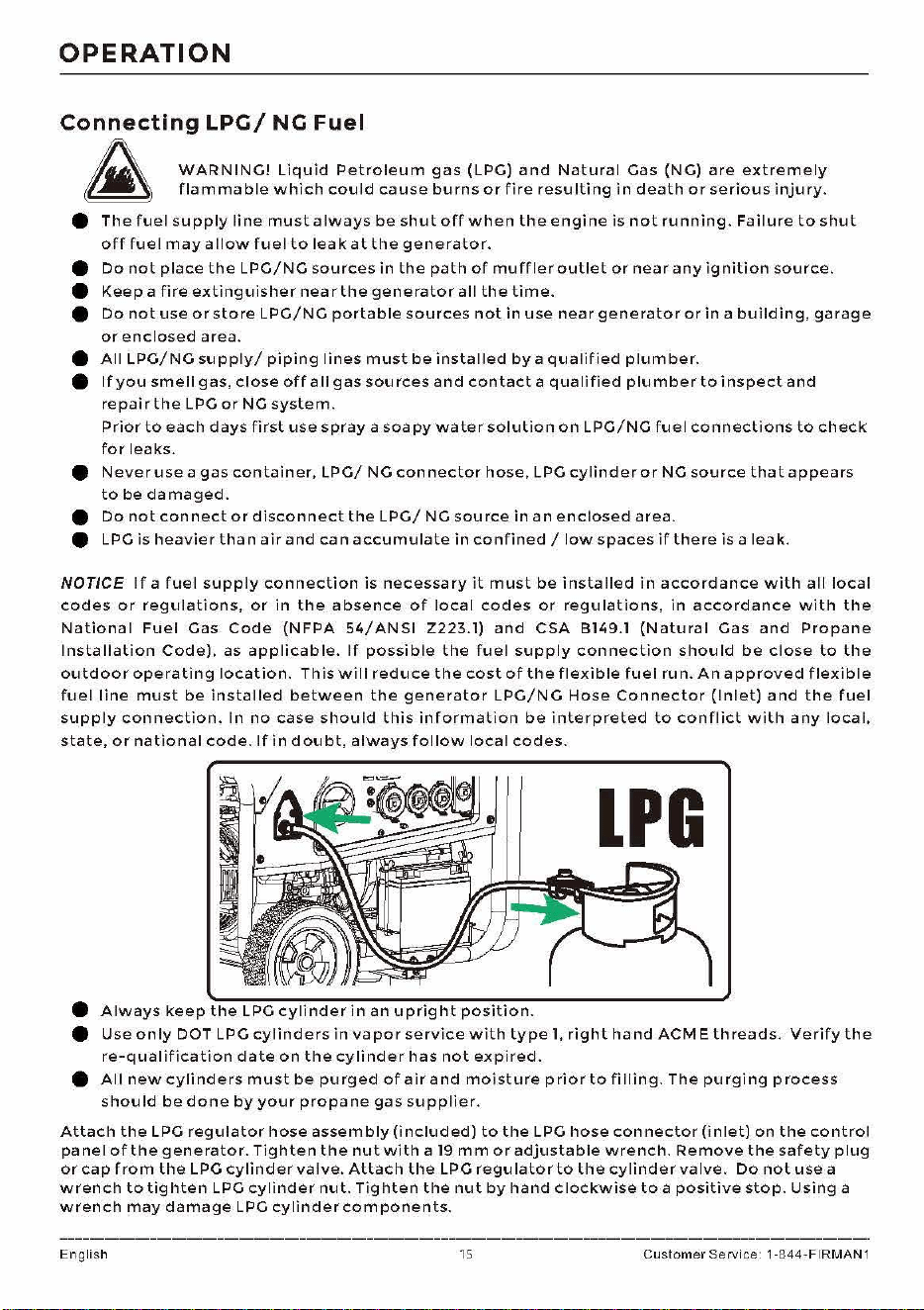
Attach
the
LPG
regulator
hose
assembly
(included)
to
the
LPG
hose
connector
(inlet)
on
the
control
panel
of
the
generator.
Tighten
the
nut
with
a
19
mm
or
adjustable
wrench.
Remove
the
safety
plug
or
cap
from
the
LPG
cylinder
valve.
Attach
the
LPG
regulator
to
the
cylinder
valve.
Do
not
use
a
wrench
to
tighten
LPG
cylinder
nut.
Tighten
the
nut
by
hand
clockwise
to
a
positive
stop.
Using
a
wrench
may
damage
LPG
cylinder
components.
English
15
Customer
Service 1-844-FIRMAN1
OPERATION
NG
NG
Shut
Off
Valve
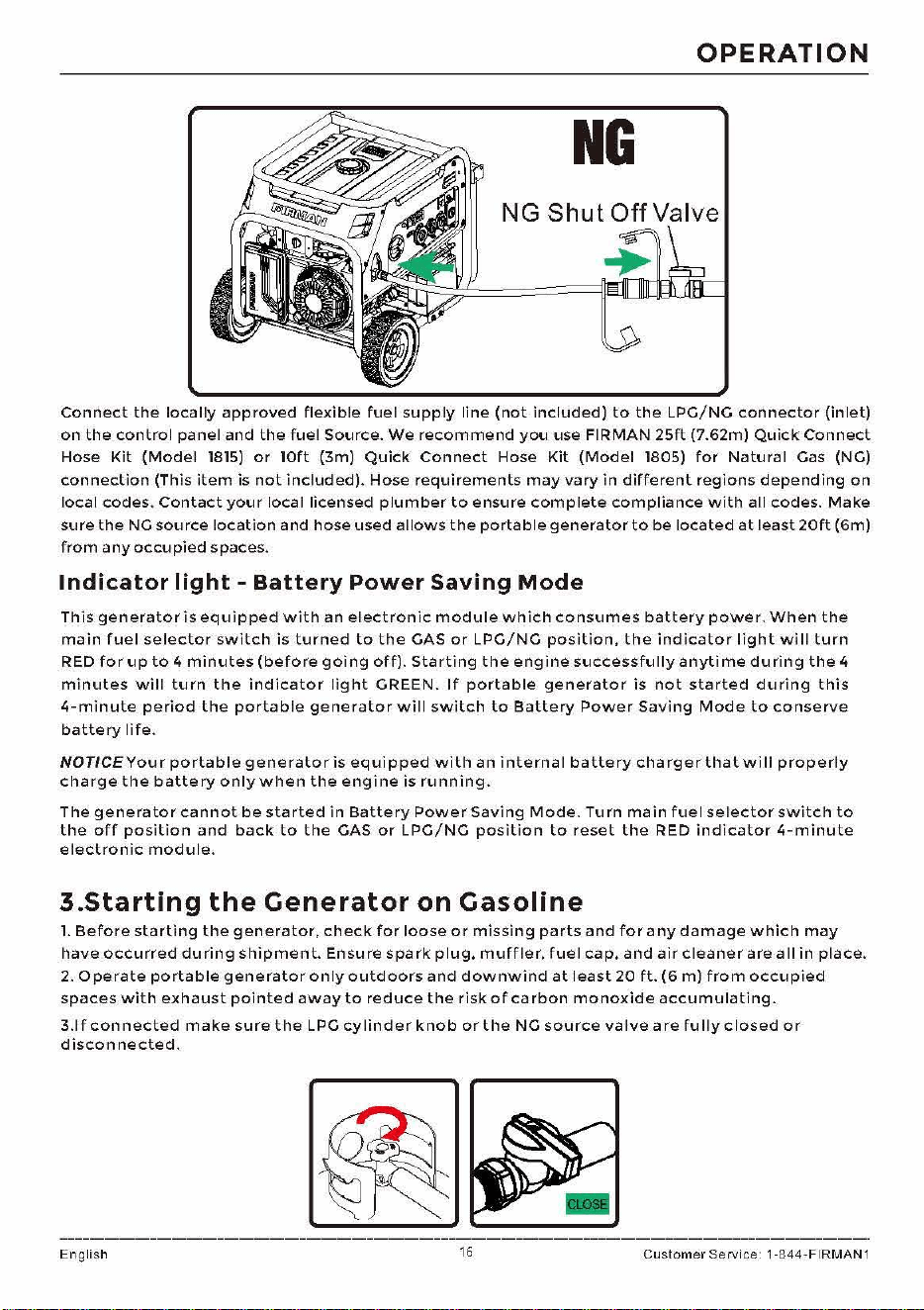
Connect
the
locally
approved
flexible
fuel
supply
line
(not
included)
to
the
LPG/NG
connector
(inlet)
on
the
control
panel
and
the
fuel
Source.
We
recommend
you
use FIRMAN
25ft
(7.62m)
Quick
Connect
Hose
Kit
(Model
1815)
or
10ft
(3m)
Quick
Connect
Hose
Kit
(Model
1805)
for
Natural
Gas (NG)
connection
(This
item
is
not
included).
Hose
requirements
may
vary
in
different
regions
depending
on
local
codes.
Contact
your
local
licensed
plumber
to
ensure
complete
compliance
with
all
codes.
Make
sure
the
NG
source
location
and
hose
used
allows
the
portable
generator
to
be
located
at
least20ft
(Gm)
from
any
occupied
spaces.
Indicator
light
-
Battery
Power
Saving
Mode
This
generator
is
equipped
with
an
electronic
module
which
consumes
battery
power.
When
the
main
fuel
selector
switch
is
turned
to
the
GAS
or
LPG/NG
position,
the
indicator
light
will
turn
RED
for
up
to
4
minutes
(before
going
off).
Starting
the
engine
successfully
anytime
du
ring
the
4
minutes
will
turn
the
indicator
light
GREEN.
If
portable
generator
is
not
started
during
this
4-minute
period
the
portable
generator
will
switch
to
Battery
Power
Saving
Mode
to
conserve
battery
life.
NOTICE
Your
portable
generator
is
equipped
with
an
internal
battery
charger
that
wi
II
properly
charge
the
battery
only
when
the
engine
is
running.
The
generator
cannot
be
started
in
Battery
Power
Saving
Mode.
Turn
main
fuel
selector
switch
to
the
off
position
and
back
to
the
GAS
or
LPG/NG
position
to
reset
the
RED
indicator
4-minute
electronic
module.
3.Starting
the
Generator
on
Gasoline
l.
Before
starting
the
generator,
check
for
loose
or
missing
parts
and
for
any
damage
which
may
have
occurred
during
shipment.
Ensure
spark
plug,
muffler,
fuel
cap,
and
air
cleaner
are
all
in
place.
2.
Operate
portable
generator
only
outdoors
and
downwind
at
least20
ft.
(6
m)
from
occupied
spaces
with
exhaust
pointed
away
to
reduce
the
risk
of
carbon
monoxide
accumulating.
3.1
f
connected
make
sure
the
LPG
cylinder
knob
or
the
NG
source
valve
a
re
fully
closed
or
disconnected.
English
16
Customer
Service 1-844-FIRMAN1
OPERATION
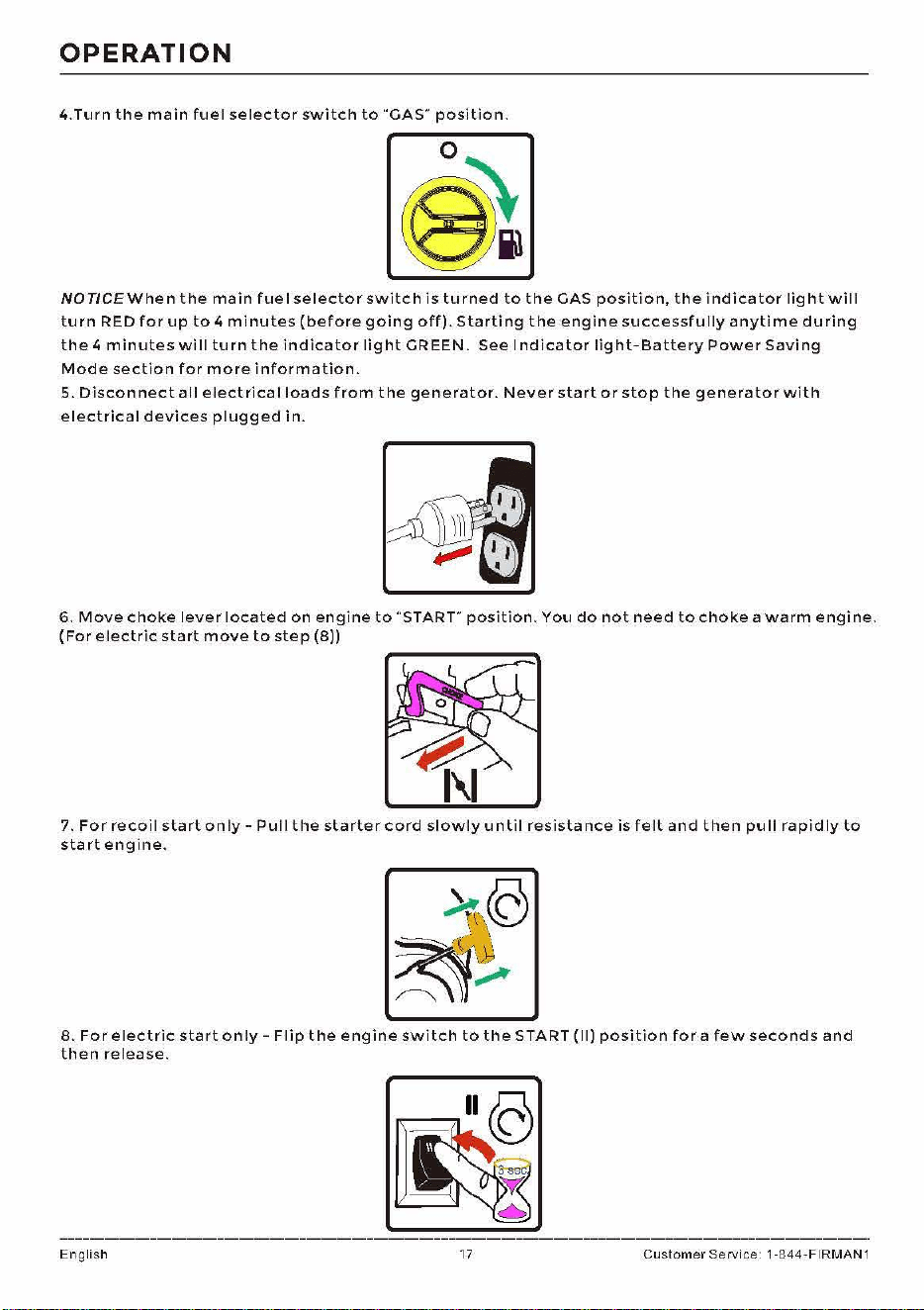
4.Turn
the
main
fuel
selector
switch
to
"'GAS"
position.
NOT/CE
When
the
main
fuel
selector
switch
is
turned
to
the
GAS
position,
the
indicator
light
will
turn
RED
for
up
to
4
minutes
(before
going
off).
Starting
the
engine
successfully
anytime
during
the
4
minutes
wi
11
turn
the
indicator
light
GREEN.
See
Indicator
light-Battery
Power
Saving
Mode
section
for
more
information.
5.
Disconnect
all
electrical
loads
from
the
generator.
Never
start
or
stop
the
generator
with
electrical
devices
plugged
in.
6.
Move
choke
lever
located
on
engine
to
"START"
position.
You
do
not
need
to
choke
a
warm
engine.
(For
electric
start
move
to
step
(8))
7.
For
recoil
start
only
-
Pul
1
the
starter
cord
slowly
until
resista
nee
is
felt
and
then
pu
11
rapidly
to
start
engine.
8.
For
electric
start
only
-
Flip
the
engine
switch
to
the
START
(11)
position
for
a
few
seconds
and
then
release.
English
17
Customer
Service 1-844-FIRMAN1
OPERATION
9.
Do
not
over-choke.
As
soon
as
engine
starts
and
warms
up,
slowly
move
the
choke
lever
to
the
RUN
position.
10.
Allow
portable
generator
to
run
at
no
load
for
a
few
minutes
to
stabilize
before
plugging
in
any
electrica
I
devices.
NOTICE
If
engine
starts
but
fails
to
run,
or
if
portable
generator
shuts
down
during
ope
ration,
check
oil
level.
See
Low
Oil
Shutdown
section
for
more
information.
4.
Starting
the
Generator
on
LPG
l.
Before
starting
the
generator,
check
for
loose
or
missing
parts
and
for
any
damage
which
may
have
occurred
during
shipment.
Ensure
spark
plug,
muffler,
fuel
cap,
and
air
cleaner
are
all
in
place.
2.
Operate
portable
generator
only
outdoors
and
downwind
at
least
20
ft.
(6
m)
from
occupied
spaces
with
exhaust
pointed
away
to
reduce
the
risk
of
carbon
monoxide
accumulating.
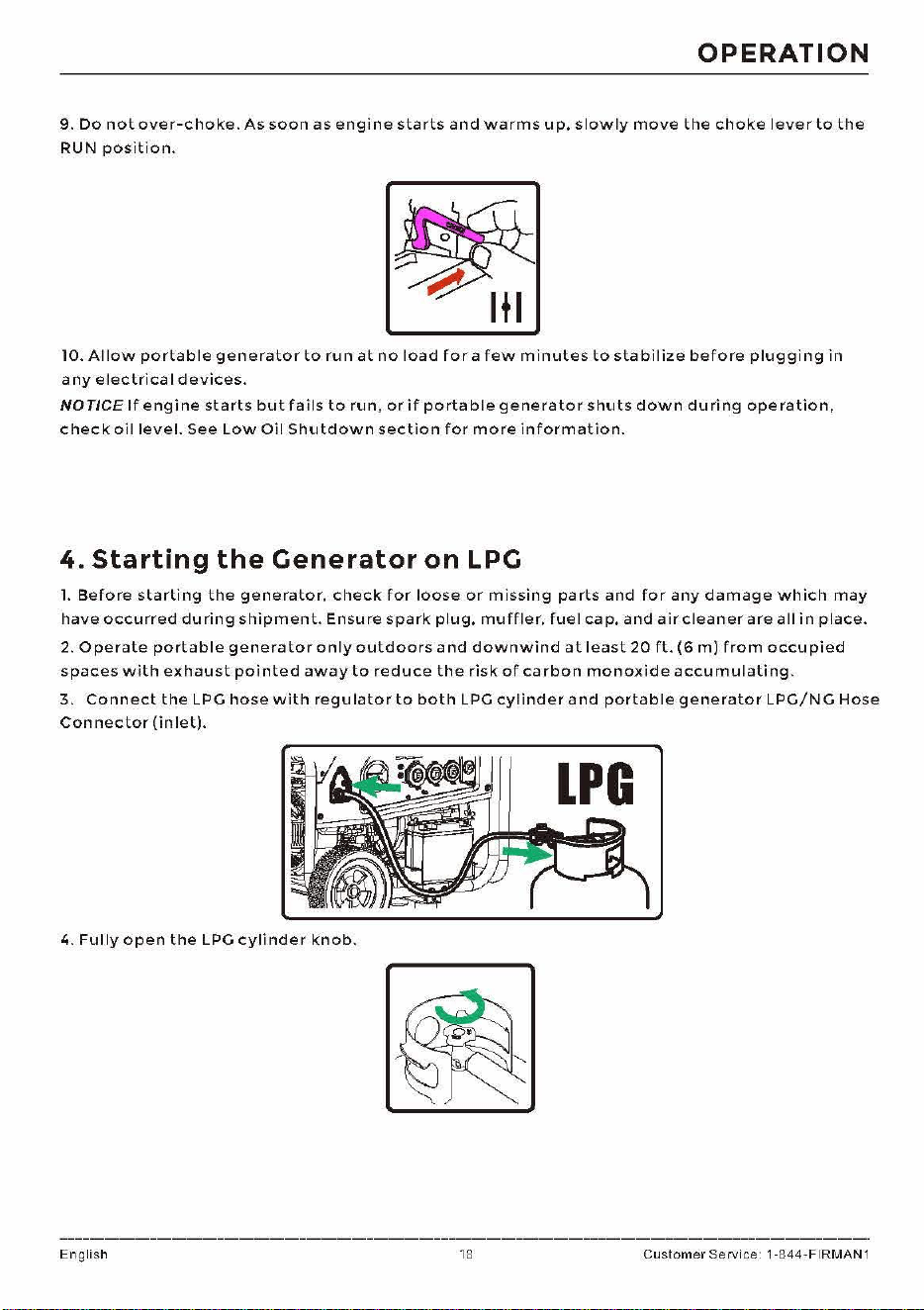
3.
Connect
the
LPG
hose
with
regulator
to
both
LPG
cylinder
and
portable
generator
LPG/NG
Hose
Connector
(in
let).
4.
Fully
open
the
LPG
cylinder
knob.
English 18
Customer
Service 1-844-FIRMAN1
OPERATION
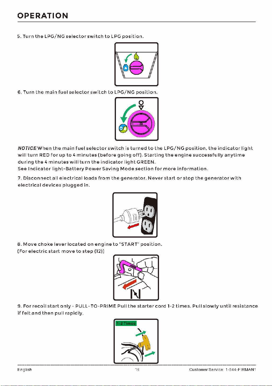
5.
Turn
the
LPG/NG
selector
switch
to
LPG
position.
6.
Turn
the
main
fuel
selector
switch
to
LPG/NG
position.
NOTICE
When
the
main
fuel
selector
switch
is
turned
to
the
LPG/NG
position,
the
indicator
light
will
turn
RED
for
up
to
4
minutes
(before
going
off).
Starting
the
engine
successfully
anytime
during
the
4
minutes
wil
I
turn
the
indicator
light
GREEN.
See
Indicator
light-Battery
Power
Saving
Mode
section
for
more
information.
7.
Disconnect
a
II
electrica
I
loads
from
the
gene
rater.
Never
start
or
stop
the
generator
with
electrical
devices
plugged
in.
8.
Move
choke
lever
located
on
engine
to
'"START"
position.
(For
electric
start
move
to
step
(12))
9.
For
recoi
I
start
only
-
PU
LL-TO-PRIME
Pul
I
the
starter
cord
1-2
ti
mes.
Pul
I
slowly
until
resistance
if
felt
and
then
pull
rapidly.
English
19
Customer
Service 1-844-FIRMAN1
OPERATION
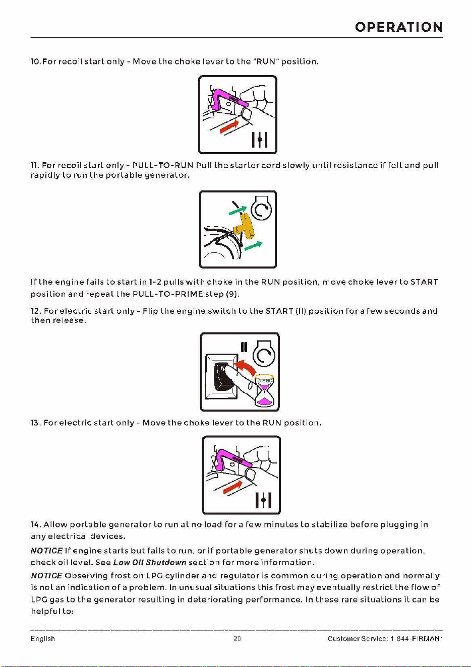
10.For
recoil
start
only-
Move
the
choke
lever
to
the
"RUN"
position.
11.
For
recoil
start
only
-
PU
LL-TO-RUN
Pu
II
the
starter
cord
slowly
u
nti
I
resistance
if
felt
and
pu
II
rapidly
to
run
the
portable
generator.
If
the
engine
fai
Is
to
start
in
1-2
pulls
with
choke
in
the
RUN
position,
move
choke
lever
to
START
position
and
repeat
the
PULL-TO-PRIME
step
(9).
12.
For
electric
start
only-
Flip
the
engine
switch
to
the
START
(11)
position
for
a
few
seconds
and
then
release.
13.
For
electric
start
only-
Move
the
choke
lever
to
the
RUN
position.
14.
Allow
portable
generator
to
run
at
no
load
for
a
few
minutes
to
stabilize
before
plugging
in
any
electrical
devices.
NOTICE
If
engine
starts
but
fails
to
run,
orif
portable
generator
shuts
down
during
operation,
check
oil
level.
See
Low
Oil
Shutdown
section
for
more
information.
NOTICE
Observing
frost
on
LPG
cylinder
and
regulator
is
common
during
operation
and
normally
is
not
an
indication
of
a
problem.
In
unusual
situations
this
frost
may
eventually
restrict
the
flow
of
LPG
gas
to
the
generator
resulting
in
deteriorating
performance.
In
these
rare
situations
it
can
be
helpful
to,
English 20
Customer
Service 1-844-FIRMAN1
OPERATION
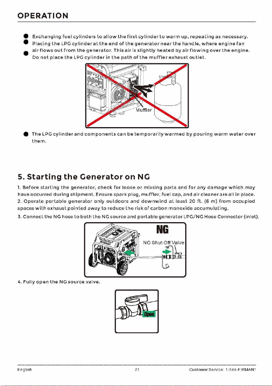
e
Exchanging
fuel
cylinders
to
allow
the
first
cylinder
to
warm
up,
repeating
as
necessary.
•
Placing
the
LPG
cylinder
at
the
end
of
the
generator
near
the
hand
le,
where
engine
fan
•
air
flows
out
from
the
generator.
This
air
is
slightly
heated
by
air
flowing
over
the
engine.
Do
not
place
the
LPG
cylinder
in
the
path
of
the
muffler
exhaust
outlet.
e
The
LPG
cylinder
and
components
can
be
temporarily
warmed
by
pouring
warm
water
over
them.
5.
Starting
the
Generator
on
NC
l.
Before
starting
the
generator,
check
for
loose
or
missing
parts
and
for
any
damage
which
may
have
occurred
during
shipment.
Ensure
spark
plug,
muffler,
fuel
cap,
and
air
cleaner
are
all
in
place.
2.
Operate
portable
generator
only
outdoors
and
downwind
at
least
20
ft.
(6
m)
from
occupied
spaces
with
exhaust
pointed
away
to
reduce
the
risk
of
carbon
monoxide
accumulating.
3.
Connect
the
NG
hose
to
both
the
NG
source
and
portable
generator
LPG/NG
Hose
Connector
(inlet).
NG
4.
Fully
open
the
NG
source
valve.
English
21
Customer
Service 1-844-FIRMAN1
OPERATION
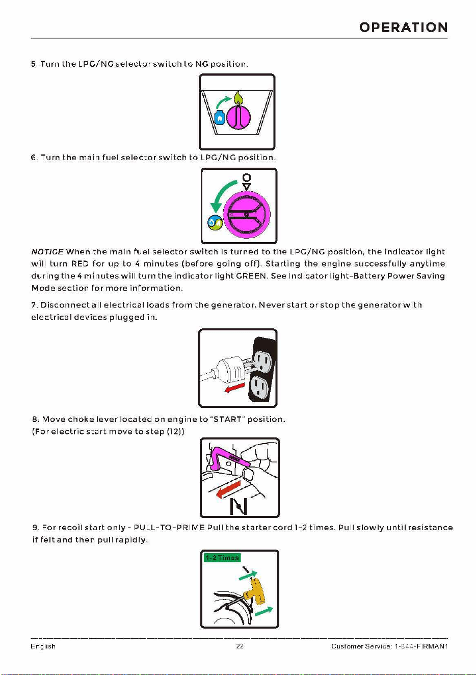
5.
Turn
the
LPG/NG
selector
switch
to
NG
position.
6.
Turn
the
main
fuel
selector
switch
to
LPG/NG
position.
NOTICE
When
the
main
fuel
selector
switch
is
turned
to
the
LPG/NG
position,
the
indicator
light
will
turn
RED
for
up
to
4
minutes
(before
going
off).
Starting
the
engine
successfully
anytime
during
the
4
minutes
will
turn
the
indicator
light
GREEN.
See
Indicator
light-Battery
Power
Saving
Mode
section
for
more
information.
7.
Disconnect
a
II
electrical
loads
from
the
generator.
Never
start
or
stop
the
generator
with
electrical
devices
plugged
in.
8.
Move
choke
lever
located
on
engine
to
"START"
position.
(For
electric
start
move
to
step
(12))
9.
For
recoil
start
only-
PU
LL-TO-PRIME
Pul
I
the
starter
cord
1-2
ti
mes.
Pu
II
slowly
u
nti
I
resistance
if
felt
and
then
pull
rapidly.
English
22
Customer
Service 1-844-FIRMAN1
OPERATION
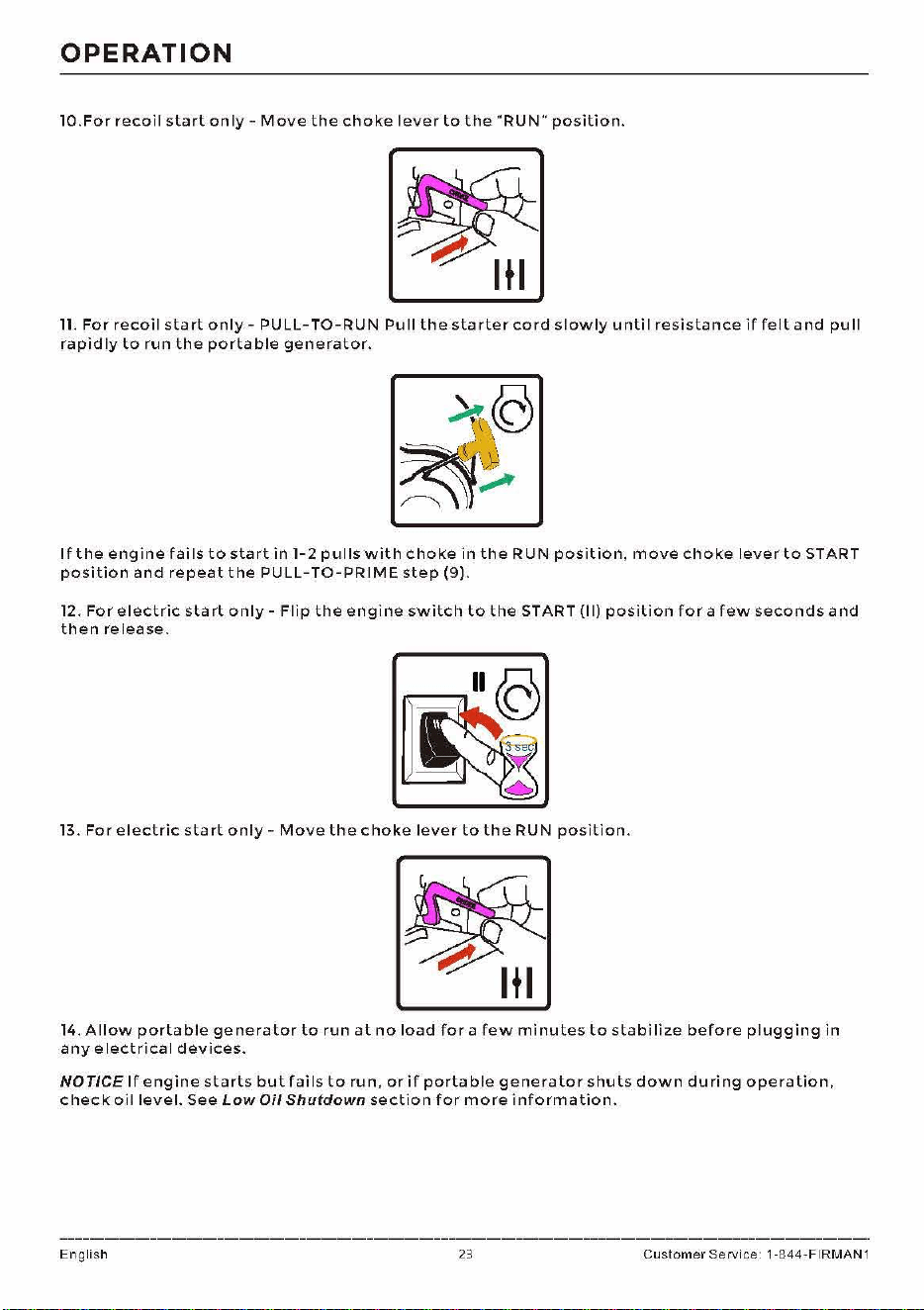
10.For
recoil
start
only-
Move
the
choke
lever
to
the
"RUN"
position.
11.
For
recoil
start
only
-
PU
LL-TO-RUN
Pu
II
the
starter
cord
slowly
u
nti
I
resistance
if
felt
and
pu
II
rapidly
to
run
the
portable
generator.
If
the
engine
fai
Is
to
start
in
1-2
pulls
with
choke
in
the
RUN
position,
move
choke
lever
to
START
position
and
repeat
the
PULL-TO-PRIME
step
(9).
12.
For
electric
start
only-
Flip
the
engine
switch
to
the
START
(11)
position
for
a
few
seconds
and
then
release.
13.
For
electric
start
only-
Move
the
choke
lever
to
the
RUN
position.
14.
Allow
portable
generator
to
run
at
no
load
for
a
few
minutes
to
stabilize
before
plugging
in
any
electrical
devices.
NOTICE
If
engine
starts
but
fails
to
run,
orif
portable
generator
shuts
down
during
operation,
check
oil
level.
See
Low
Oil Shutdown
section
for
more
information.
English 23
Customer
Service 1-844-FIRMAN1
OPERATION
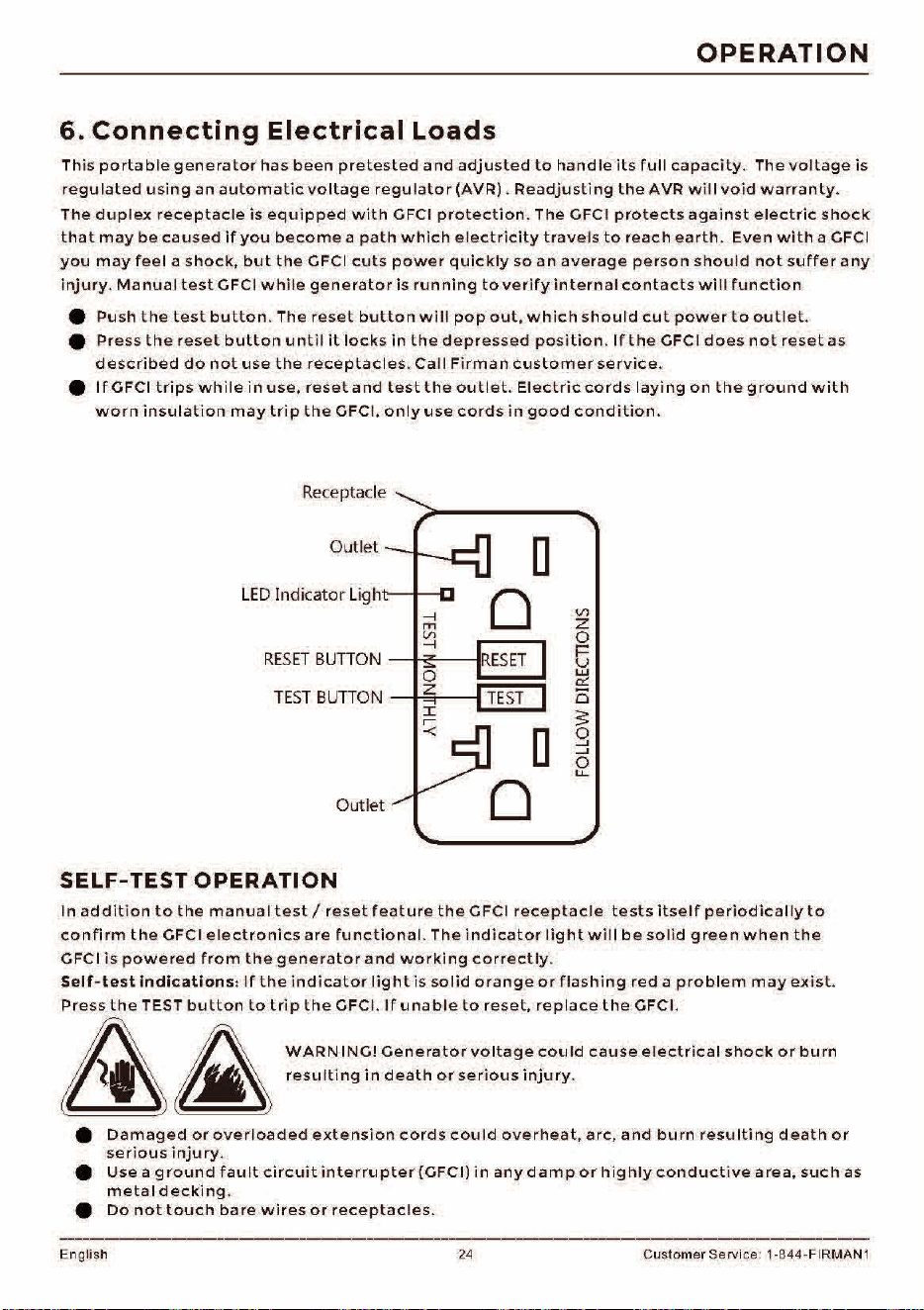
6.
Connecting
Electrical
Loads
This
portable
generator
has
been
pretested
and
adjusted
to
handle
its
full
capacity.
The
voltage
is
regulated
using
an
automatic
voltage
regulator
(AVR).
Readjusting
the
AVR
will
void
warranty.
The
duplex
receptacle
is
equipped
with
GFCI
protection.
The
GFCI
protects
against
electric
shock
that
may
be
caused
if
you
become
a
path
which
el
ectricity
travels
to
reach
earth.
Even
with
a GFCI
you
may
feel
a
shock,
but
the
GFCI
cuts
power
quickly
so
an
average
person
should
not
suffer
any
injury.
Manual
test
GFCI
while
generator
is
running
to
verify
internal
contacts
will
function
e
Push
the
test
button
.
The
reset
button
will
pop
out,
which
should
cut
power
to
outlet.
e
Press
the
reset
button
until
it
locks
in
the
depressed
position
.
If
the
GFCI
does
not
reset
as
described
do
not
use
the
receptacles
.
Call
Firman
customer
service.
e
If
GFCI
trips
while
in
use
,
reset
and
test
the
outlet.
Electric
cords
laying
on
the
ground
with
worn
insulation
may
trip
the
GFCI,
only
use
cords
in
good
condition.
Receptacle
Ou
t
let
D
0
RESET
BUTTON
-1-<"-----IKESET
TEST
BUTTON
---tt-=----il
TEST
Outlet
SELF-TEST
OPERATION
Vl
z
0
t5
w
er:.
0
3:
g
-'
0
u...
In
addit
i
on
to
the
manual
test/
reset
feature
the
GFCI
receptacle
tests
itself
per
i
odically
to
confirm
the
GFCI e l
ectronics
are
functional.
The
indicator
light
will
be
solid
green
when
the
GFCI
is
powered
f r
om
the
generator
and
working
correctly
.
Self-test
indications:
If
the
indicator
light
is
solid
orange
or
flashing
red
a
problem
may
ex
i
st.
Press
the
TEST
button
to
trip
the
GFCI.
If
unable
to
reset,
replace
the
GFCI.
8 A
WARN
INCi
Geoe,a<o"o"age
coo
Id
caose
eleddcal
s,oc,
o,
0orn
~
-
resulting
in
death
or
serious
injury
.
e
Damaged
or
overloaded
extension
cords
could
overheat
,
arc,
and
burn
resulting
death
or
serious
injury.
e
Use
a
ground
fault
circuit
interrupter(GFCI)
in
any
damp
or
highly
conductive
area,
such
as
metal
decking.
e
Do
not
touch
bare
wires
or
receptac
les.
English 24 Customer Servi
ce
: 1-844-FIRMAN 1
OPERATION
e
Do
not
use
generator
with
electrical
cords
which
are
worn,
frayed,
bare
or
otherwise
damaged
.
Do
not
operate
generator
in
the
rain
or
wet
weather
.
Do
not
run
indoors
to
avoid
wet
conditions
.
•
•
•
Do
not
handle
generator
or
electrical
cords
while
standing
in
water,
while
barefoot,
or
while
e
hands
or
feet
a re
wet.
Use
listed
transfer
switch
to
prevent
backfeed
by
isolating
generator
from
electric
utility
workers.
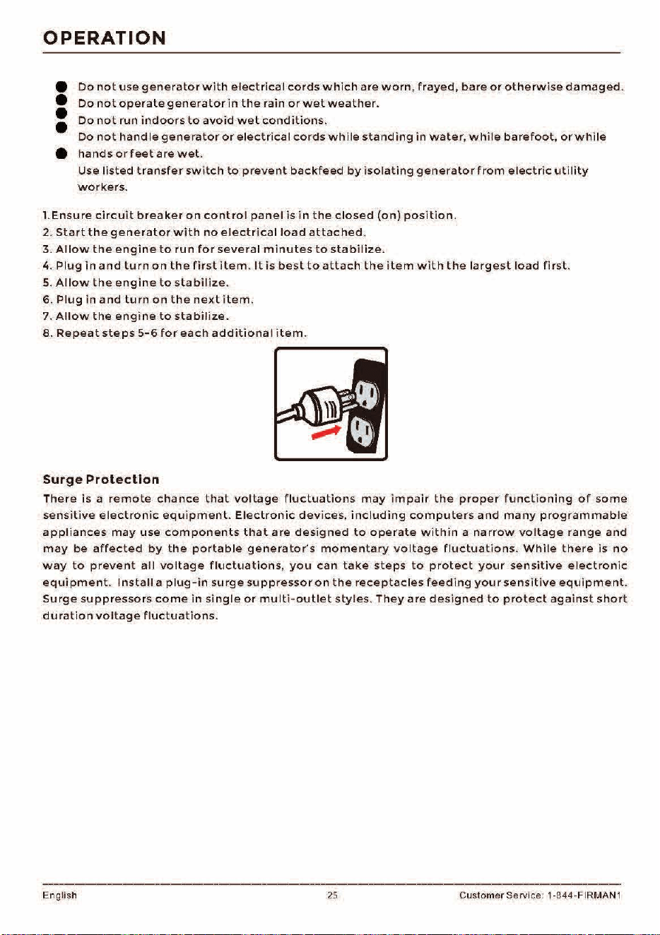
I.Ensure
circuit
breaker
on
control
panel
is
in
the
closed
(on)
position.
2.
Start
the
generator
with
no
electrical
load
attached.
3.
Allow
the
engine
to
run
for
several
minutes
to
stabilize.
4.
Plug
in
and
turn
on
the
first
item.
It
is
best
to
attach
the
item
with
the
largest
load
first.
5.
Allow
the
engine
to
stabilize.
6.
Plug
in
and
turn
on
the
next
item.
7.
Allow
the
engine
to
stabilize.
8.
Repeat
steps
5-6
for
each
additional
item.
Surge
Protection
There
is
a
remote
chance
that
voltage
fluctuations
may
impair
the
proper
functioning
of
some
sensitive
electronic
equipment.
Electronic
devices,
including
computers
and
many
programmable
appliances
may
use
components
that
are
designed
to
operate
within
a
narrow
voltage
range
and
may
be
affected
by
the
portable
generator's
momentary
voltage
fluctuations.
While
there
is
no
way
to
prevent
all
voltage
fluctuations,
you
can
take
steps
to
protect
your
sensitive
electronic
equipment.
Install
a
plug-in
surge
suppressor
on
the
receptacles
feeding
your
sensitive
equipment
.
Surge
suppressors
come
in
single
or
multi-outlet
styles.
They
are
designed
to
protect
against
short
duration
voltage
fluctuations.
English
25
Customer Service: 1-844-FIRMAN 1
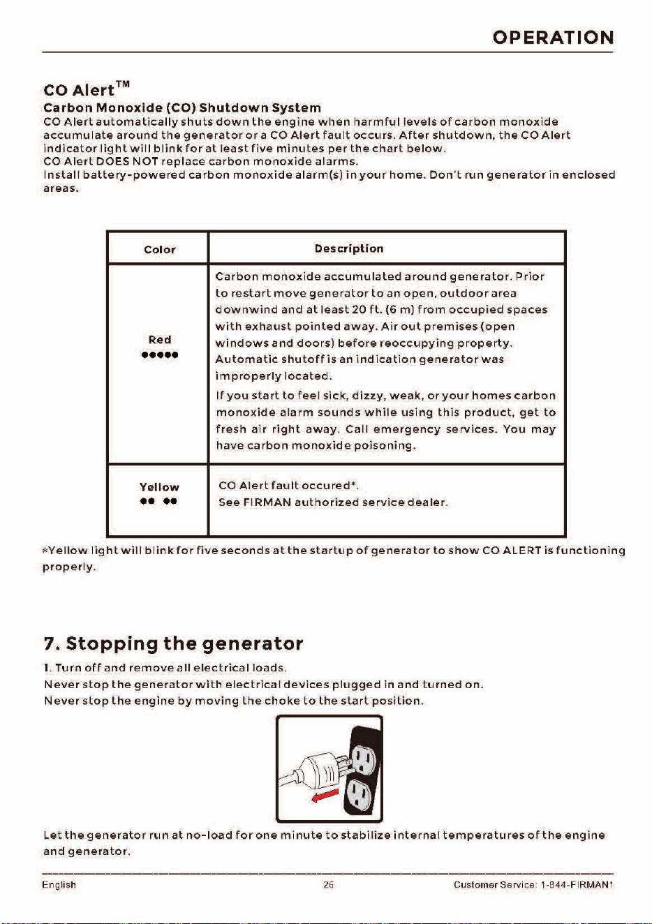
OPERATION
CO
Alert
TM
Carbon
Monoxide
(CO)
Shutdown
System
CO
Alert
automatically
shuts
down
the
engine
when
harmful
levels
of
carbon
monox
i
de
accumulate
around
the
generator
or
a
CO
Alert
fault
occurs
.
After
shutdown,
the
CO
Alert
indicator
light
will
blink
for
at
least
five
minutes
per
the
chart
below.
CO
Alert
DOES
NOT
replace
carbon
monoxide
alarms.
Install
battery-powered
carbon
monoxide
alarm(s)
in
your
home.
Don
't
run
generator
in
enclosed
areas.
Color
Description
Carbon
monoxide
accumulated
around
generator.
Prior
to
restart
move
generator
to
an
open,
outdoor
area
downwind
and
at
least
20
ft.
(6
m)
from
occupied
spaces
with
exhaust
pointed
away.
Air
out
premises
(open
Red
windows
and
doors)
before
reoccupying
property
.
•••••
Automatic
shutoff
is
an
indication
generator
was
improperly
located.
If
you
start
to
feel
sick,
dizzy,
weak
,
or
your
homes
carbon
monoxide
alarm
sounds
while
using
this
product,
get
to
fresh
air
right
away.
Call
emergency
services.
You
may
have
carbon
monoxide
poisoning.
Yellow
CO
Alert
fault
occured•.
••
••
See
Fl
RMAN
authorized
service
dealer
.
*
Yellow
light
will
blink
for
five
seconds
at
the
startup
of
generator
to
show
CO
ALERT
is
functioning
properly.
7.
Stopping
the
generator
1.
Turn
off
and
remove
all
electrical
loads.
Never
stop
the
generator
with
electrical
devices
plugged
in
and
turned
on.
Never
stop
the
engine
by
moving
the
choke
to
the
start
position
.
Let
the
generator
run
at
no-load
for
one
minute
to
stabilize
i
nterna
I
tempera
tu
res
of
the
engine
and
generator.
Eng
li
sh 26 Customer Servi
ce
: 1-844-FIRMAN 1
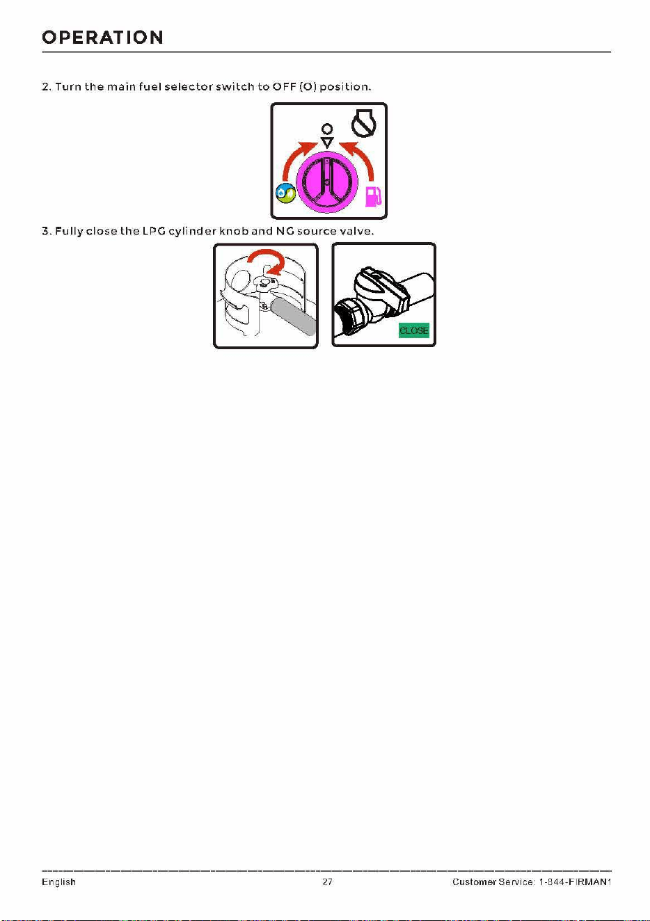
OPERATION
2.
Turn
the
main
fuel
selector
switch
to
OFF
(O)
position.
3.
Fully
close
the
LPG
cylinder
knob
and
NG
source
valve.
English 27
Customer
Service 1-844-FIRMAN1
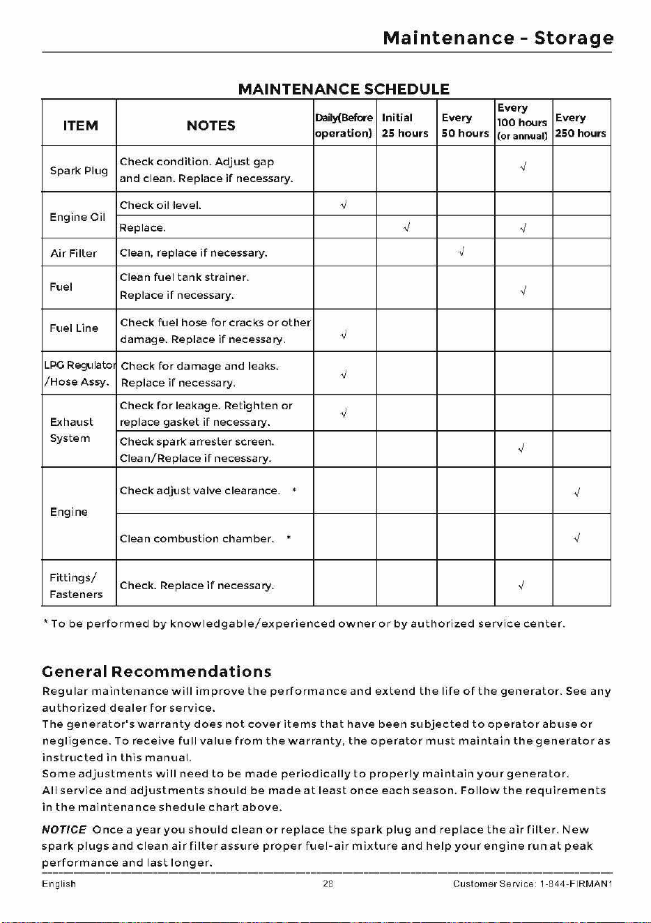
Maintenance
-
Storage
MAINTENANCE
SCHEDULE
Daily(Before
Initial Every
Every
ITEM
NOTES
100 hours
Every
operation)
25
hours
so
hours
(or annual)
250
hours
Spark
Plug
Check
condition.
Adjust
gap
✓
and
clean. Replace
if
necessary.
Check
oil
level.
✓
Engine
Oil
Replace.
✓
✓
Air
Filter
Clean, replace
if
necessary.
✓
Clean
fuel
tank
strainer.
Fuel
Replace
if
necessary.
✓
Fuel Line
Check
fuel
hose
for
cracks
or
other
damage.
Replace
if
necessary.
✓
LPG
Regulator
Check
for
damage
and
leaks.
✓
/Hose
Assy.
Replace
if
necessary.
Check
for
leakage.
Retighten
or
✓
Exhaust replace
gasket
if
necessary.
System
Check
spark
arrester
screen.
✓
Clean/Replace
if
necessary.
Check
adjust
valve
clearance.
.
✓
Engine
Clean
combustion
chamber.
.
✓
Fittings/
Fasteners
Check. Replace
if
necessary.
✓
•Tobe
performed
by
knowledgable/experienced
owner
or
by
au
t
horized
service
center.
General
Recommendations
Regular
maintenance
will
improve
the
performance
and
extend
the
life
of
the
gene
r
ator.
See
any
authorized
dealer
for
service.
The
generator's
warranty
does
not
cover
items
that
have
been
subjected
to
operator
abuse
or
negligence.
To
receive
full
value
from
the
warranty,
the
operator
must
maintain
the
generator
as
instructed
in
this
manual.
Some
adjustments
will
need
to
be
made
periodically
to
prope
r
ly
maintain
your
generat
o r.
All
se
r
vice
and
adjustments
should
be
made
at
least
once
each
season.
Follow
the
requi
r
ements
in
the
maintenance
shedule
chart
above.
NOTICE
Once
a
year
you
should
clean
or
replace
the
spark
plug
and
replace
the
air
filter.
New
spark
plugs
and
clean
air
filter
assure
proper
fuel-air
mixture
and
help
your
engine
ru n
at
peak
performance
and
last
longer.
English 28 Custo
me
r Service 1-844-FIRMA
N1
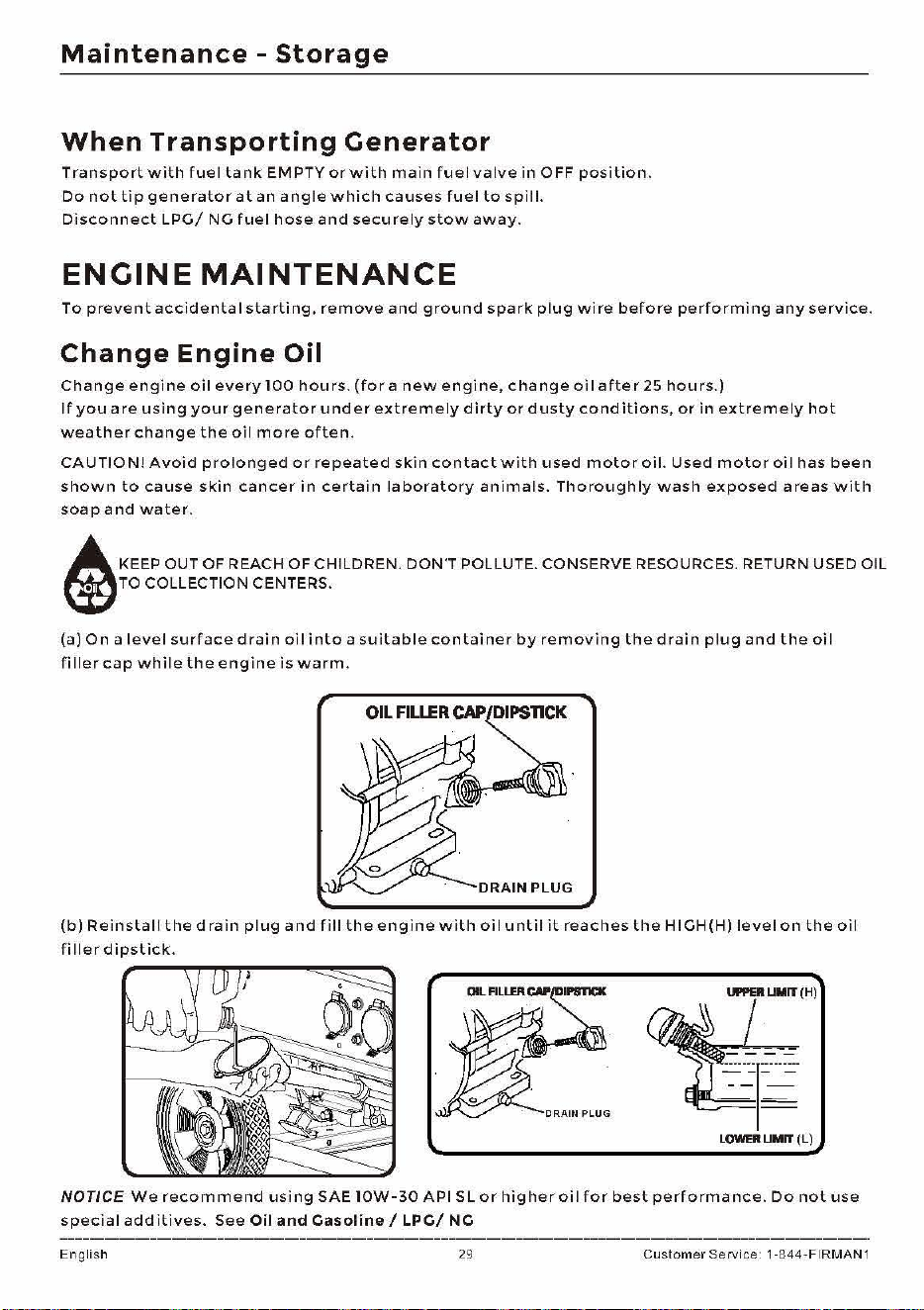
Maintenance
-
Storage
When
Transporting
Generator
Transport
with
fuel
tank
EMPTY
or
with
main
fuel
valve
in
OFF
position.
Do
not
tip
generator
at
an
angle
which
causes
fuel
to
spill.
Disconnect
LPG/
NG
fuel
hose
and
securely
stow
away.
EN
CINE
MAINTENANCE
To
prevent
accidental
starting,
remove
and
ground
spark
plug
wire
before
performing
any
service.
Change
Engine
Oil
Change
engine
oil
every
100
hours.
(for
a
new
engine,
change
oi
I
after
25
hours.)
If
you
a
re
using
your
generator
under
extremely
dirty
or
dusty
conditions,
or
in
extremely
hot
weather
change
the
oil
more
often.
CAUTION!
Avoid
prolonged
or
repeated
skin
contact
with
used
motor
oil.
Used
motor
oil
has
been
shown
to
cause
skin
cancer
in
certain
laboratory
animals.
Thoroughly
wash
exposed
areas
with
soap
and
water.
A KEEP OUT OF REACH
OF
CHILDREN. DON'T POLLUTE. CONSERVE RESOURCES. RETURN USED OIL
WTO
COLLECTION CENTERS.
(a)
On
a
level
surface
drain
oil
into
a
suitable
container
by
removing
the
drain
plug
and
the
oil
filler
cap
while
the
engine
is
warm.
OIL
FILLER
CAP
DIPSTICK
(b)
Reinstal
I
the
drain
plug
and
fill
the
engine
with
oi
I
until
it
reaches
the
HIGH
(HJ
level
on
the
oil
filler
dipstick.
LOWER
LIMIT
(L)
NOTICE
We
recommend
using
SAE
I0W-30
API
SL
or
higher
oil
for
best
performance.
Do
not
use
special
additives.
See
Oil
and
Casoline
/
LPC/
NC
English 29
Customer
Service 1-844-FIRMAN1
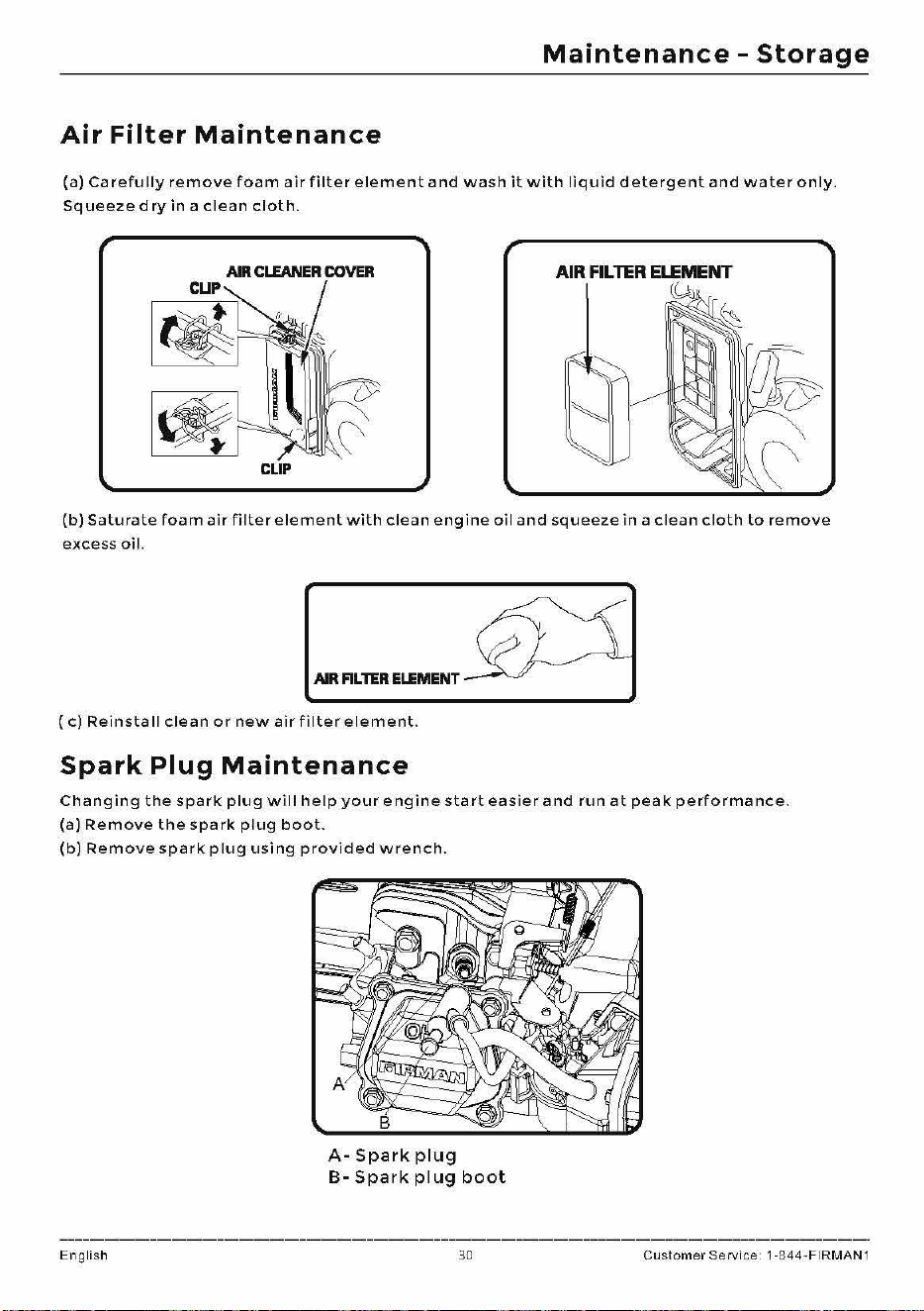
Maintenance
-
Storage
Air
Filter
Maintenance
(a)
Carefully
remove
foam
air
filter
element
and
wash
it
with
liquid
detergent
and
water
only.
Squeezed
ry
in
a
clean
cloth.
AIR
CLEANER
COVER
CUP
CLIP
tf
(b)
Saturate
foam
air
filter
element
with
clean
engine
oil
and
squeeze
in
a
clean
cloth
to
remove
excess
oil.
AIR
FILTER
ELEMENT
(
c)
Reinsta
II
clean
or
new
air
filter
element.
Spark
Plug
Maintenance
Changing
the
spark
plug
will
help
your
engine
start
easier
and
run
at
peak
performance.
(a)
Remove
the
spark
plug
boot.
(b)
Remove
spark
plug
using
provided
wrench.
A-
Spark
plug
B-
Spark
plug
boot
English 30
Customer
Service 1-844-FIRMAN1
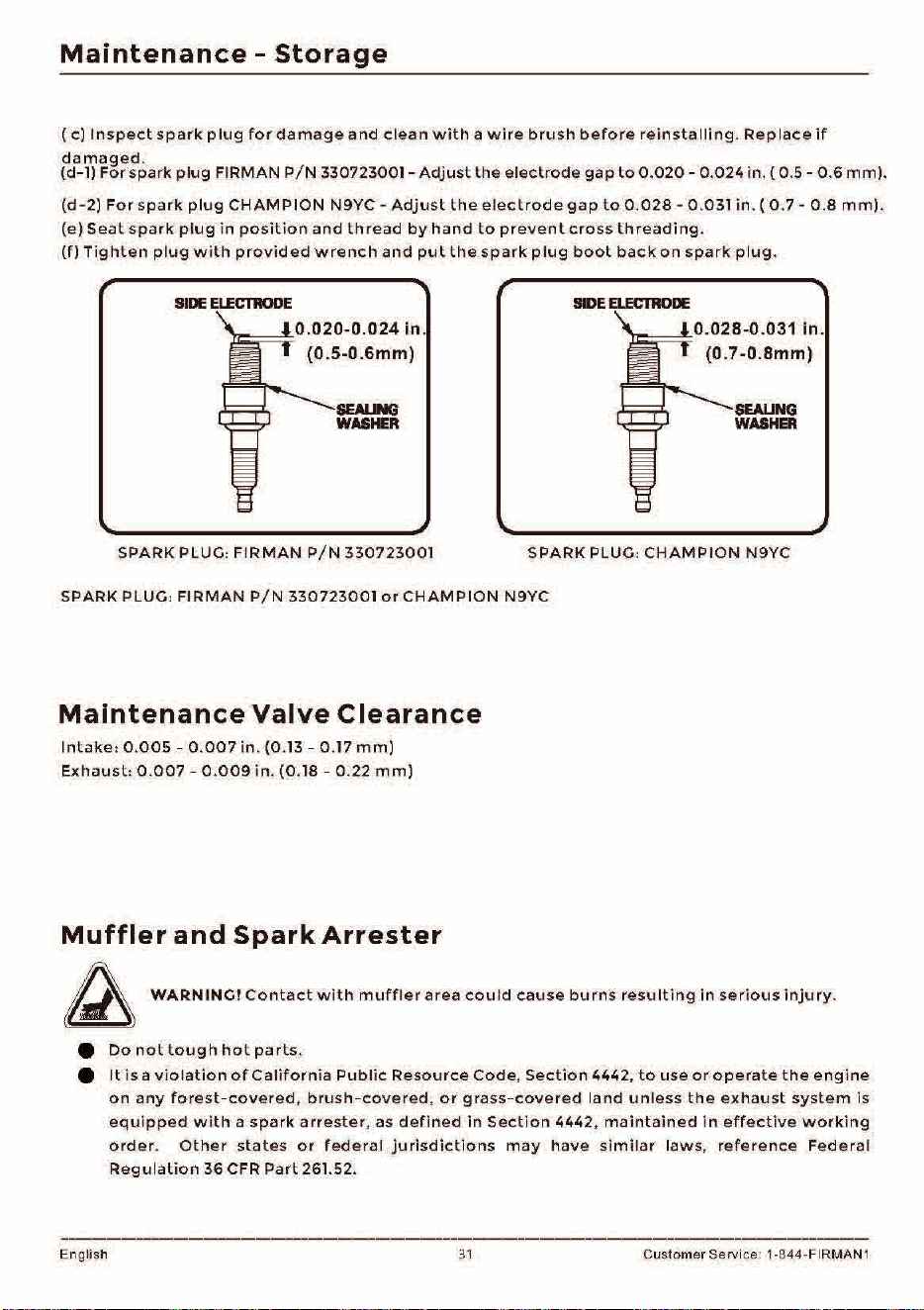
Maintenance
-
Storage
(
c)
Inspect
spark
p l
ug
for
damage
and
clean
with
a
wire
brush
before
reins
ta
Iii
ng
.
Rep
lace
if
damaged
.
(d-1)
For
spark
plug
FI
RMAN
P
/N
330723001 -
Adjust
the
electrode
gap
to
0.020
-
0.024
in.
( 0.5 - 0.6
mm).
(d-2)
For
spark
plug
CHAMPION
N9YC
-
Adjust
the
electrode
gap
to
0.
028
-
0.031
in
. (
0.7
- 0 .8
mm).
(e)
Seat
spark
plug
in
position
and
thread
by
hand
to
prevent
cross
threading.
(fl
Tighten
plug
w i
th
provided
wrench
and
put
the
spa
rk
plug
boot
back
on
spark
plug
.
SIDE
El.ECTllODE
_ _
-1.0.020-0.024
In.
(0.5-0.6mm)
SEALING
WASHER
SPARK
PLUG:
FIRMAN
P/N
330723001
SIDE
ELECTIIODE
0.028-0
.031
In.
(0.7-0.Bmm)
SEAUNG
WASHER
SPARK
PLUG:
CHAMPION
N9YC
SPARK PLUG:
FIRMAN
P/N
330723001
or
CHAMPION
N9YC
Maintenance
Valve
Clearance
Intake:
0.
005
-
0.007
in.
(0.13 - 0.17
mm)
Exhaust:
0.007
-
0.009
in.
(0.18 - 0.22
mm)
Muffler
and
Spark
Arrester
~
WARN
INC!
Contact
with
muffler
area
cou
ld
cause
burns
resulting
in
serious
injury.
e
Do
not
tough
hot
parts.
e
It
is
a
violation
of
California
Public
Resource
Code.
Section
4442.
to
use
or
operate
the
engine
on
any
fo
r
est-covered
.
brush-covered,
or
grass-covered
land
unless
the
exhaust
system
is
equipped
with
a
spark
arreste
r, as
defined
in
Section
4442
,
maintained
in
effective
working
order
.
Other
states
or
federal
jurisdic
t
ions
may
have
s
imilar
laws,
reference
Federal
Regulation
36
CFR
Part
261.52.
Eng
li
sh 31 Customer Servi
ce
: 1-844-FIRMAN 1
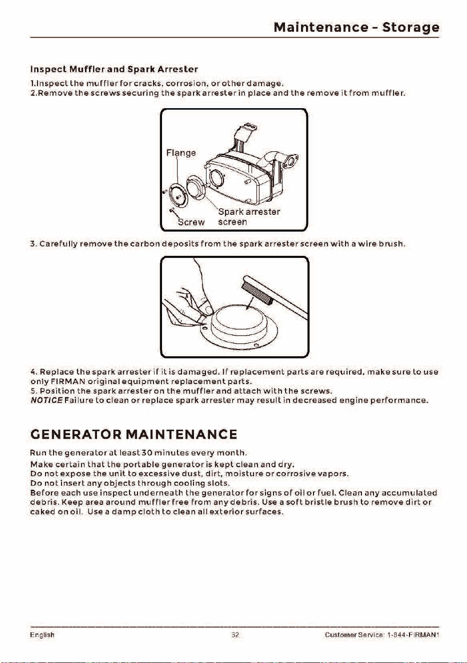
Maintenance
-
Storage
Inspect
Muffler
and
Spark
Arrester
I.Inspect
the
muffler
for
cracks,
corrosion,
or
other
damage.
2.Remove
the
screws
securing
the
spark
arrester
in
place
and
the
remove
it
from
muffler.
Flange
"'
"'-
-
Spark
arrester
Screw
screen
3.
Carefully
remove
the
carbon
deposits
from
the
spark
arrester
screen
with
a
wire
brush.
4.
Replace
the
spark
arrester
if
it
is
damaged.
If
replacement
parts
are
required,
make
sure
to
use
only
FIRMAN
original
equipment
replacement
parts.
5.
Position
the
spark
arrester
on
the
muffler
and
attach
with
the
screws.
NOTICE
Failure
to
clean
or
replace
spark
arrester
may
result
in
decreased
engine
performance.
CENERATOR
MAINTENANCE
Run
the
generator
at
least
30
minutes
every
month.
Make
certain
that
the
portable
generator
is
kept
clean
and
dry.
Do
not
expose
the
unit
to
excessive
dust,
dirt,
moisture
or
corrosive
vapors.
Do
not
insert
any
objects
through
cooling
sl
o
ts.
Before
each
use
inspect
underneath
the
generator
for
signs
of
oil
or
fue
I.
Clean
any
accumulated
debris.
Keep
area
around
muffler
free
from
any
debris.
Use a
soft
bristle
brush
to
remove
di
rt
o r
caked
on
oil.
Use
a
damp
cloth
to
clean
all
exterior
surfaces.
Eng
li
sh 32 Custom
er
Servi
ce
: 1-844-FIRMAN 1
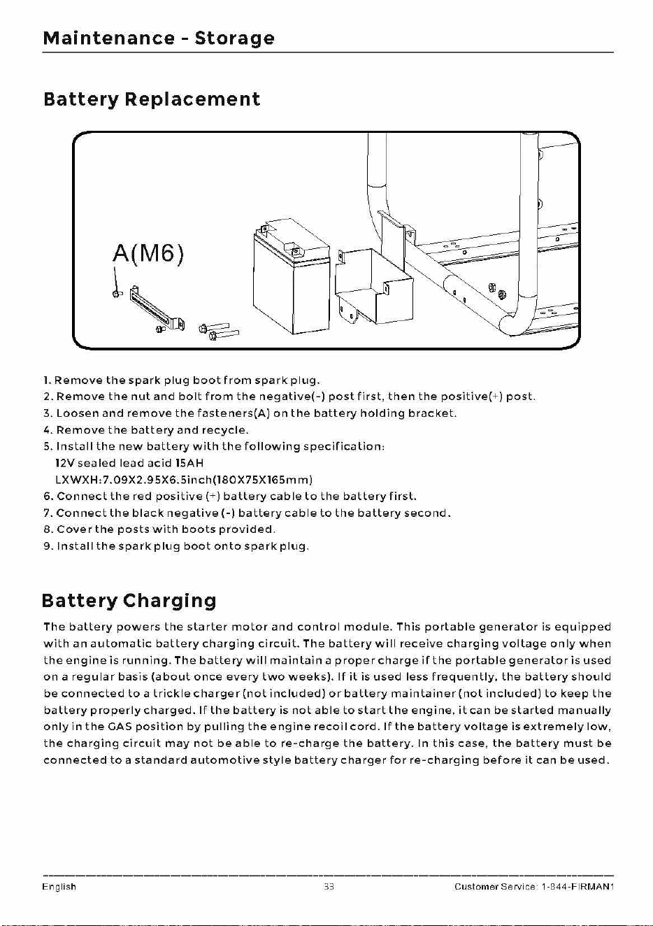
Maintenance
-
Storage
Battery
Replacement
A(M6)
~~
l.
Remove
the
spark
plug
boot
from
spark
plug.
2.
Remove
the
nut
and
bolt
from
the
negative(-)
post
first,
then
the
positive(
+)
post.
3.
Loosen
and
remove
the
fasteners(A)
on
the
battery
holding
bracket.
4.
Remove
the
battery
and
recycle.
5.
Install
the
new
battery
with
the
following
specification,
12V
sealed
lead
acid
lSAH
LXWXH:7.09X2.95X6.5inch(l80X75Xl65mm)
6.
Connect
the
red
positive(
+)
battery
cable
to
the
battery
first.
7.
Connect
the
black
negative(-)
battery
cable
to
the
battery
second.
8.
Cover
the
posts
with
boots
provided.
9.
Install
the
spark
plug
boot
onto
spark
plug.
Battery
Charging
The
battery
powers
the
starter
motor
and
control
module.
This
portable
generator
is
equipped
with
an
automatic
battery
charging
circuit.
The
battery
will
receive
charging
voltage
only
when
the
engine
is
running.
The
battery
will
maintain
a
proper
charge
if
the
portable
generator
is
used
on
a
regular
basis
(about
once
every
two
weeks).
If
it
is
used
less
frequently,
the
battery
should
be
connected
to
a
trickle
charger
(not
included)
or
battery
maintainer(not
included)
to
keep
the
battery
properly
charged.
If
the
battery
is
not
able
to
start
the
engine,
it
can
be
started
manually
only
in
the
GAS
position
by
pulling
the
engine
recoil
cord.
If
the
battery
voltage
is
extremely
low,
the
charging
circuit
may
not
be
able
to
re-charge
the
battery.
In
this
case,
the
battery
must
be
connected
to
a
standard
automotive
style
battery
charger
for
re-charging
before
it
can
be
used.
English 33
Customer
Service 1-844-FIRMAN1
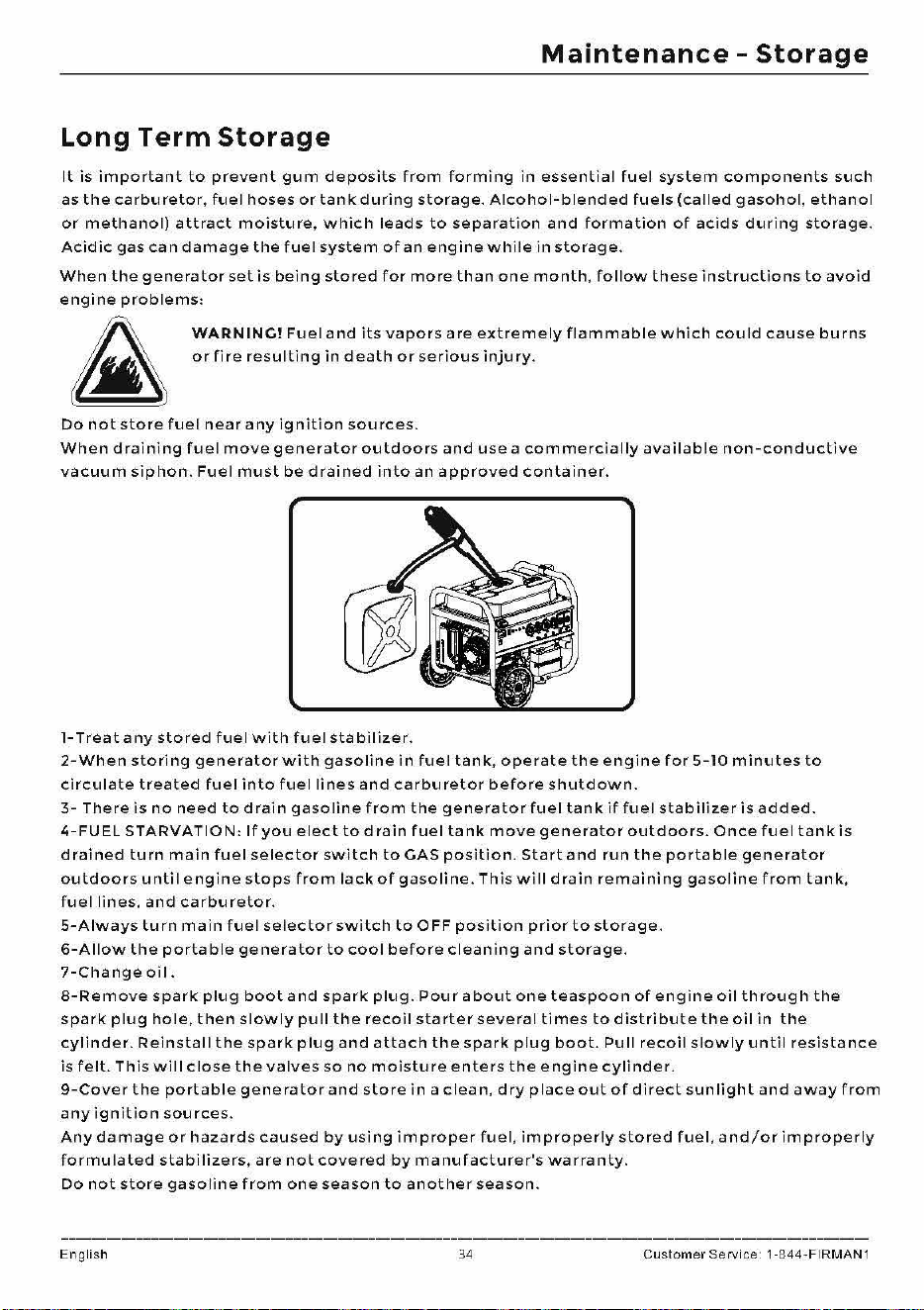
Maintenance
-
Storage
Long
Term
Storage
It
is
important
to
prevent
gum
deposits
from
forming
in
essential
fuel
system
components
such
as
the
carburetor,
fuel
hoses
or
tank
during
storage.
Alcohol-blended
fuels
(called
gasohol,
ethanol
or
methanol)
attract
moisture,
which
leads
to
separation
and
formation
of
acids
during
storage.
Acidic
gas
can
damage
the
fuel
system
of
an
engine
while
in
storage.
When
the
generator
set
is
being
stored
for
more
than
one
month,
follow
these
instructions
to
avoid
engine
problems:
WARN
INC!
Fuel
and
its
vapors
are
extremely
flammable
which
could
cause
burns
or
fire
resulting
ind
eath
or
serious
injury.
Do
not
store
fuel
near
any
ignition
sources.
When
draining
fuel
move
generator
outdoors
and
use
a
commercially
available
non-conductive
vacuum
siphon.
Fuel
must
be
drained
into
an
approved
container.
1-Treat
any
stored
fuel
with
fuel
stabilizer.
2-When
storing
generator
with
gasoline
in
fuel
tank,
operate
the
engine
for
5-10
minutes
to
circulate
treated
fuel
into
fuel
lines
and
carburetor
before
shutdown.
3-
There
is
no
need
to
drain
gasoline
from
the
generator
fuel
tank
if
fuel
stabilizer
is
added.
4-FUEL
STARVATION:
If
you
elect
to
drain
fuel
tank
move
generator
outdoors.
Once
fuel
tank
is
drained
turn
main
fuel
selector
switch
to
CAS
position.
Start
and
run
the
portable
generator
outdoors
until
engine
stops
from
lack
of
gasoline.
This
will
drain
remaining
gasoline
from
tank,
fuel
lines,
and
carburetor.
5-Always
turn
main
fuel
selector
switch
to
OFF
position
prior
to
storage.
6-Allow
the
portable
generator
to
cool
before
cleaning
and
storage.
7-Changeoil.
8-Remove
spark
plug
boot
and
spark
plug.
Pour
about
one
teaspoon
of
engine
oil
through
the
spark
plug
hole,
then
slowly
pull
the
recoil
starter
several
times
to
distribute
the
oil
in
the
cylinder.
Reinstall
the
spark
plug
and
attach
the
spark
plug
boot.
Pull
recoil
slowly
until
resistance
is
felt.
Th is
will
close
the
valves
so
no
moisture
enters
thee
ngine
cylinder.
9-Cover
the
portable
generator
and
store
in
a
clean,
dry
place
out
of
direct
sun
light
and
away
from
any
ignition
sources.
Any
damage
or
hazards
caused
by
using
improper
fuel,
improperly
stored
fuel,
and/or
improperly
for
mu
lated
stabilizers.
are
not
cove
red
by
manufacturer's
warranty.
Do
not
store
gasoline
from
one
season
to
another
season.
English
34
Customer
Service 1-844-FIRMAN1
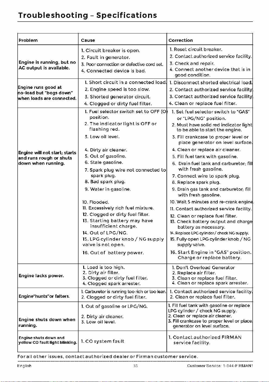
Troubleshooting
-
Specifications
Problem Cause Correction
1.
Circuit
breaker
is
open.
l. Reset
circuit
breaker.
2.
Fault
in
generator.
2.
Contact
authorized
service facility.
Engine
is
running,
but
no
3.
Poor connection
or
defective cord
set
3.
Check
and
repair.
AC
output
is available.
4.
Connected
device
is
bad.
4.
Connect
another
device
that
is
in
good
condition.
l.
Short
circuit
in
a
connected
load
l.
Disconnect
shorted
electrical
load.
Engine runs good
at
2.
Engine
speed
is
too
slow.
2.
Contact
authorized
service
facility
,-io-load
but
"bogs down"
when loads are connected.
3.
Shorted
generator
circuit.
3.
Contact
authorized
service
facility
4.
Clogged
or
dirty
fuel
filter.
4.
Clean
or
replace
fuel
filter.
l. Fuel
selector
switch
set
to
OFF (O
l.
Set
fuel
selector
switch
to
"GAS"
position.
or"
LPG/NG"
position.
2.
The
indicator
light
is
OFF
or
2.
Must
have
solid
red
indicator
light
flashing
red.
to
be
able
to
start
the
engine.
3.
Low
oil
level.
3.
Fill crankcase
to
proper
level
or
place
generator
on
level surface
Engine will
not
start; starts
4.
Dirty
air
cleaner.
4. Clean
or
replace
air
cleaner.
and runs rough
or
shuts
5.
Out
of
gasoline.
5.
Fill
fuel
tank
with
gasoline.
down
when
running.
6. Sta le gasoline.
6.
Drain fuel
tank
and carburetor; fill
7.
Spark
plug
wire
not
connected
to
with
fresh gasoline.
spark
plug.
7.
Connect
wire
to
spark
plug.
8. Bad
spark
plug.
8. Replace spark plug.
9.
Water
in
gasoline. 9. Drain gas
tank
and carburetor; fill
with
fresh gasoline.
10. Flooded.
10.
Wait
5 minutes and re-crank
enginE
.
11.
Excessively
rich
fuel
mixture.
11.
Contact
authorized service facility.
12.
Clogged
or
dirty
fuel
filter.
12.
Clean
or
replace
fuel
filter.
13.
Starting
battery
may
have
13.
Check
battery
output
and
charge
insufficient
charge.
battery
as necessary.
14.
Out
of
LPG/NG.
14.
Replace
LPG
cylinder/
check
NG
supply.
15. LPG
cylinder
knob/
NG
supply
15.
Fully open
LPG
cylinder
knob/
NG
valve
is
not
open.
supply
valve.
16.
Out
of
battery
power.
16.
Start
Engine
in
"GAS"
position.
Charge
or
replace
battery.
l.
Load is
too
high.
l.
Don't
Overload
Generator
Engine lacks
power.
2.
Dirty
air
filter.
2.
Replace
air
filter.
3.
Clogged
or
dirty
fuel
filter.
3. Clean
or
replace
fuel
filter.
4.
Clogged
spark
arrester.
4. Clean
or
replace
spark
arrester.
l. Carburetor is running
too
rich
or
too
lean.
l.
Contact
authorized
service
facility
Engine"hunts"or falters.
2.
Clogged
or
dirty
fuel
filter.
2.
Clean
or
replace
fuel
filter.
l.
Out
of
gasoline
or
LPG/NG.
l. Fill fuel
tank
with
gasoline
or
replace
LPG
cylinder/
check
NG
supply.
Engine shuts down
when
2.
Dirty
air
cleaner.
2.
Clean
or
replace
air
cleaner.
3.
Low
oil
level.
3.
Fill crankcase
to
proper level
or
place
running.
generator on level surface.
Engine shuts
down
and
l.
Contact
authorized
FIRMAN
yellow
CO
fault
light
blinking.
1.
CO
system
fau
It
service
facility.
For
a
II
other
issues,
contact
authorized
dealer
or
Firman
customer
service.
English 35
Customer
Service 1-844-FIRMAN1
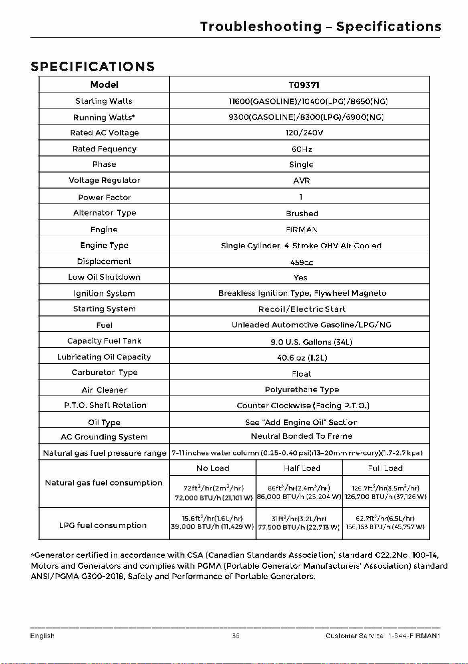
Troubleshooting
-
Specifications
SPECIFICATIONS
Model
T09371
Starting
Watts
11600(GASOLINE)/10400(LPG)/8650(NG)
Running
Watts•
9300(GASOLINE)/8300(LPG)/6900(NG)
Rated
AC
Voltage
120/240V
Rated
Fequency
G0Hz
Phase
Single
Voltage
Regulator
AVR
Power
Factor
1
Alternator
Type
Brushed
Engine
FIRMAN
Engine
Type
Single
Cylinder,
4-Stroke
OHV
Air
Cooled
Displacement
459cc
Low
Oil
Shutdown
Yes
Ignition
System
Breakless
Ignition
Type,
Flywheel
Magneto
Starting
System
Recoil/Electric
Start
Fuel
Unleaded
Automotive
Gasoline/LPG/NG
Capacity
Fuel
Tank
9.0
U.S. Gallons (34L)
Lubricating
Oil
Capacity
40.6
oz
(1.2L)
Carburetor
Type
Float
Air
Cleaner
Polyurethane
Type
P.T.O.
Shaft
Rotation
Counter
Clockwise
(Facing
P.
T.O.)
Oil
Type
See
"Add
Engine
Oil"
Section
AC
Grounding
System
Neutral
Bonded
To
Frame
Natural
gas
fuel
pressure
range
7-11
inches
water
column
(0.25-0.40
psi)(l3-20mm
mercury)(l
.
7-2.7
kpa)
No
Load
Half
Load Full Load
Natural
gas
fuel
consumption
72ft
3
/hr(2m
3
/hr)
86ft
3
/hr(2.4m
3
/hr)
126.7ft
3
/hr
(3.Sm
3
/hr)
72,000
BTU/h
(21
,
101
W)
86,000
BTU/h
(25,204 W ) 126,
700
BTU
/ h (37,126
W)
15.6
ft
3
/hr(l.6
L/hr)
3lft
3
/hr(3.2L/hr)
62.7ft3
/hr(6
.SL/hr)
LPG
fuel
consumption
39
,
000
BTU/h
(11
,429
W)
77
,
500
BTU/h
(22,713
W)
156
,163
BTU/h
(45,
757W)
*Generator
certified
in
accordance
with
CSA (Canadian
Standards
Association)
standard
C22.2No. 100-14,
Motors
and
Generators
and
complies
with
PGMA
(Portable
Generator
Manufacturers'
Association)
standard
ANSI/PGMA
G300-2018,
Safety
and
Performance
of
Portable
Generators.
English
36 Custo
mer
Service 1-8
44-FIRM
A
N1
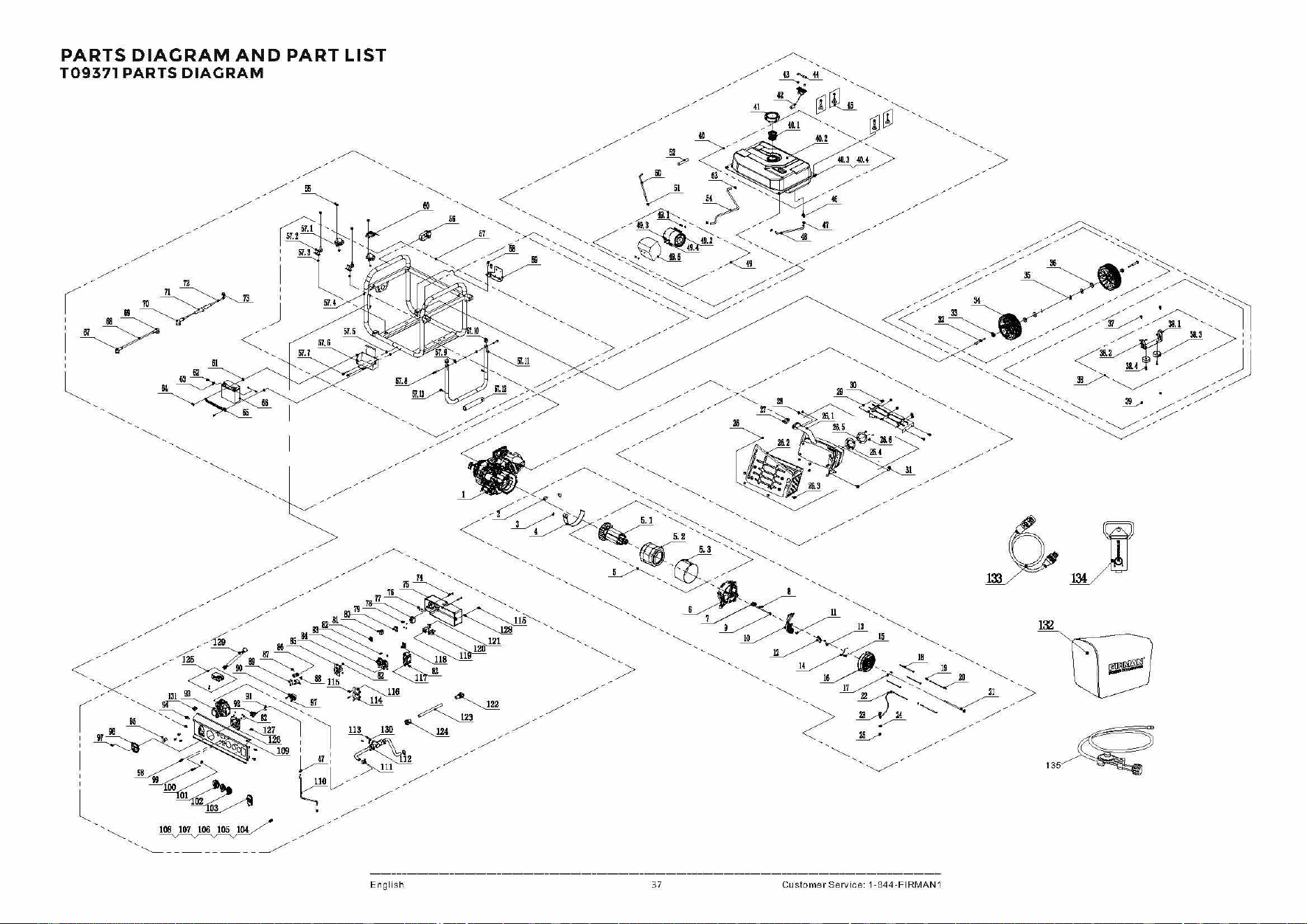
'-----
'-----
'-----
English 37 Customer Service·
.1-844-FIRMAN1
'-----
135~
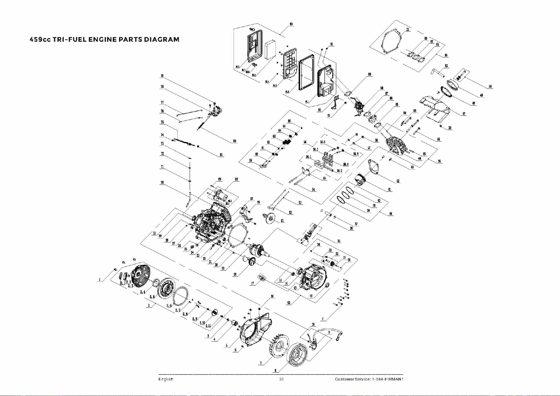
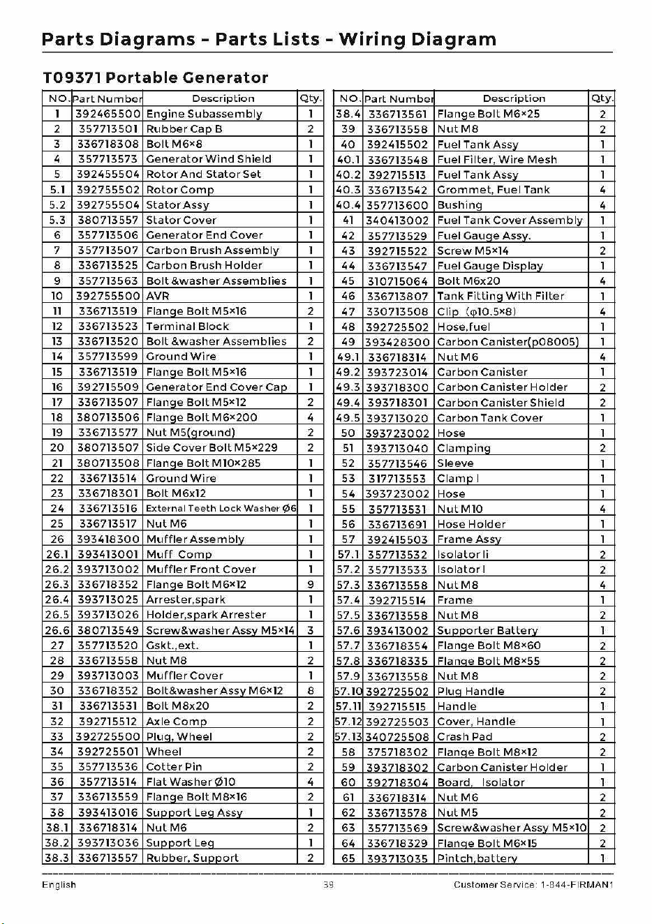
Parts
Diagrams
-
Parts
Lists
-
Wiring
Diagram
109371
Portable
Generator
NO.
Part
Number
Description
Qty.
NO.
Part
Numbe1
Description
Qty.
1
392465500
Engine
Subassembly
1
38.4
336713561
Flange
Bolt
M6X25
2
2 357713501
Rubber
Cap
B 2
39
336713558
NutM8
2
3
336718308
BoltM6x8
1
40
392415502
Fuel
TankAssv
1
4
357713573
Generator
Wind
Shield
1
40.1
336713548
Fuel
Filter,
Wire
Mesh
1
5
392455504
Rotor
And
Stator
Set
1
40.2
392715513
Fuel
TankAssv
1
5.1
392755502
Rotor
Como
1
40.3
336713542
Grommet,
Fuel
Tank
4
5.2
392755504
Stator
Assy
1
40.4
357713600
Bushing
4
5.3
380713557
Stator
Cover
1
41
340413002
Fuel
Tank
Cover
Assembly
1
6
357713506
Generator
End
Cover
1
42
357713529
Fuel
Gauae
Assv.
1
7
357713507
Carbon
Brush
Assembly
1
43
392715522
Screw
M5x14 2
8
336713525
Carbon
Brush
Holder
1
44
336713547
Fuel
Gauae
Disolav
1
9
357713563
Bolt
&washer
Assemblies
1
45
310715064
Bolt
M6x20
4
10
392755500
AVR
1
46
336713807
Tank
Fittina
With
Filter
1
11
336713519
Fla
nae
Bolt
M5x16
2
47
330713508
Clin
(m10.5x8)
4
12
336713523
Terminal
Block
1
48
392725502
Hose.fuel
1
13
336713520
Bolt
&washer
Assemblies
2
49
393428300
Carbon
Canister(o08005)
1
14
357713599
Ground
Wire
1
49.1
336718314
NutM6
4
15
336713519
Fla
nae
Bolt
M5x16
1
49.2
393723014
Carbon
Canister
1
16
392715509
Generator
End
Cover
Cao
1
49.3
393718300
Carbon
Canister
Holder
2
17
336713507
Fla
nae
Bolt
M 5x12 2
49.4
393718301
Carbon
Canister
Shield
2
18
380713506
Fla
nae
Bolt
M6X200
4
49.5
393713020
Carbon
Tank
Cover
1
19
336713577
Nut
M5(around)
2
50
393723002
Hose
1
20
380713507
Side
Cover
Bolt
M5x229
2
51
393713040
Clamoina
2
21
380713508
Fla
nae
Bolt
M10X285 1
52
357713546
Sleeve
1
22 336713514
Ground
Wire
1
53
317713553
Clamol
1
23
336718301
Bolt
M6x12 1
54
393723002
Hose
1
24
336713516
External
Teeth
Lock
Washer
¢6
1
55
357713531
Nut
Ml0
4
25
336713517
NutM6
1
56
336713691
Hose
Holder
1
26
393418300
Muffler
Assemblv
1
57
392415503
Frame
Assv
1
26.1
393413001
Muff
Como
1 57.1
357713532
Isolator
Ii
2
26.2
393713002
Muffler
Front
Cover
1
57.2
357713533
Isolator
I
2
26.3
336718352
Fla
nae
Bolt
M6X12
9
57.3
336713558
NutM8
4
26.4
393713025
Arrester,snark
1
57.4
392715514
Frame
1
26.5
393713026
Holde
r,s
nark
Arrester
1
57.5
336713558
NutM8
2
26.6
380713549
Screw&washer
Assv
M5x14
3
57.6
393413002
Su
ooorter
Batte
rv
1
27
357713520
Gskt.,ext.
1
57.7
336718354
Flanae
Bolt
M8X60
2
28
336713558
NutM8
2
57.8
336718335
Flanae
Bolt
M8x55
2
29
393713003
Muffler
Cover
1
57.9
336713558
NutM8
2
30
336718352
Bolt&washer
Assv
M6x12 8
1~7.
1(
392725502
Plua
Handle
2
31
336713531
Bolt
M8x20
2
57.11 392715515
Handle
1
32 392715512
AxleComn
2 57.1
392725503
Cover,
Handle
1
33
392725500
Plue,
Wheel
2 57.13
340725508
Crash
Pad
2
34
392725501
Wheel
2
58
375718302
Flanae
Bolt
M8X12
2
35
357713536
Cotter
Pin
2
59
393718302
Carbon
Canister
Holder
1
36
357713514
Flat
Washer¢10
4
60
392718304
Board
Isolator
1
37
336713559
Fla
nae
Bolt
M8X16
2
61
336718314
NutM6
2
38
393413016
Sunnort
Lea
Assv
1
62
336713578
NutM5
2
38.1 336718314
Nut
M6
2
63
357713569
Screw&washer
Assv
M5x10
2
38.2
393713036
Suaaort
Lea
1
64
336718329
Flanae
Bolt
M6x15 2
38.3
336713557
Rubber,
Sunnort
2
65
3q3713035
Pintch
batterv
1
English 39
Customer
Service 1-844-FIRMAN1
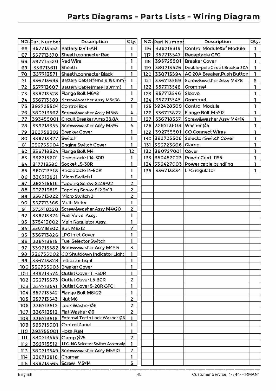
Parts
Diagrams
-
Parts
Lists
-
Wiring
Diagram
NO.
Part
Number
Description
Qty.
NO.
Part
Numbe1
Description
Qty.
66
357713553
Battery
12V
15AH
l
116
336718319
Control
Module&vf
Module
l
67
357713570
Sheath,connecter Red
l
117
357713547
Receptacle
GFCI
l
68
392715520
Red
Wire
l
118
393725501
Breaker
Cover
l
69
336713611 Sheath l
119
380713526
Double-pole
Circuit Breaker
30A
l
70
357713571 Sheath,connecter Black l
120
330713594
AC
20A
Breaker.Push
Button
l
71
336713693
Battery
Cab
I
e(female
180mm)
l
121
336713569
Screw&washer
Assv
M4x8
6
72
357713607
Batte
ry
Cable(male
180mm)
l
122
357713548
Grommet
l
73
336713528
Flange
Bolt
M6X8
l 123
357713546
Sleeve l
74
336713589
Screw&washer
Assv
MSx38
2
124
357713545
Grommet
l
75
392725504
Control
Box l 125
392428300
Control
Module
l
76
380713562
Screw&washer Assv M 5x8 4
126
336713822
Flanqe
Bolt
M5Xl2
l
77
393455001
Circuit Breaker
Amo
38.8A l 127
336718357
Screw&washer
Assv
M4xl4
l
78
336718355
Screw&washer Assv
M3x6
4 128
329713608
Washer¢5
l
79
392758302
Breaker
Cover
l
129
392755501
CO
Connect
Wires
l
80
336713827
Switch
l
130
392725506
Selector
Switch
Cover
l
81
336755004
Enaine
Switch
Cover
l
131
336723606
Clarno
l
82
336718324
Flanae
Bolt
M4
12 132
380727001
Cover
l
83
336713601
Receotacle Ll4-30R l 133
350457023
Power
Cord
1195
l
84
317713580
Socket
L5-30R l
134
336427003
Power
cable
bundlina
l
85
380713518
Receptacle 14-50R
l
135
336713834
LPG
requlator
l
86
336713821
Micro
Switch
l l
87
392715516 Taooina
Screw
St2.9X32 2
88
336713819
Taooina
Screw
St2.9xl9
2
89
336713822
Micro
Switch
2 2
90
357713586
Multi
Meter
l
91
375718320
Screw&washer Assv
M4x20
2
92
336713824
Fuel Valve Assv. l
93
375413002
Main
Raaulator Assv.
l
94
336718302
BoltM6xl2
7
95
336713826
LPG
Inlet
Cover
l
96
336713815
Fuel
Selector
Switch
l
97
330713582
Screw&washer Assv
M4xl4
3
98
336755002
CO
Shutdown
Indicator
Liaht
l
99
336713828
Indicato
r Lia
ht
l
100
336755005
Breaker
Cover
l
101
336713574
OutletCoverTT-30R
l
102
336713573
Outlet
Cover
L5-30R
2
103
357713541
Outlet
Cover
5-20R
GFCI
l
104
357713542
Flance
Bolt
M6x22 l
105
357713543
NutM6
2
106
336713512
LockWasher<2l6
2
107
336713513
Flat
Washer
<2l6
2
108
336713516
External
Teeth
Lock
Washer
¢6
l
109
393715001
Control
Panel
l
110
393755001
Hose Fuel l
lll
380713545
Clamo<2l25
2
112
392715519
LPG-NG Selector Switch Assemblv
l
113
380713549
Screw&washer Assv
M5xl0
2
114
336713818
Charaer l
115
336713565
Screw M5x14 5
English 40 Custo
me
r Service 1-844-FIRMA
N1
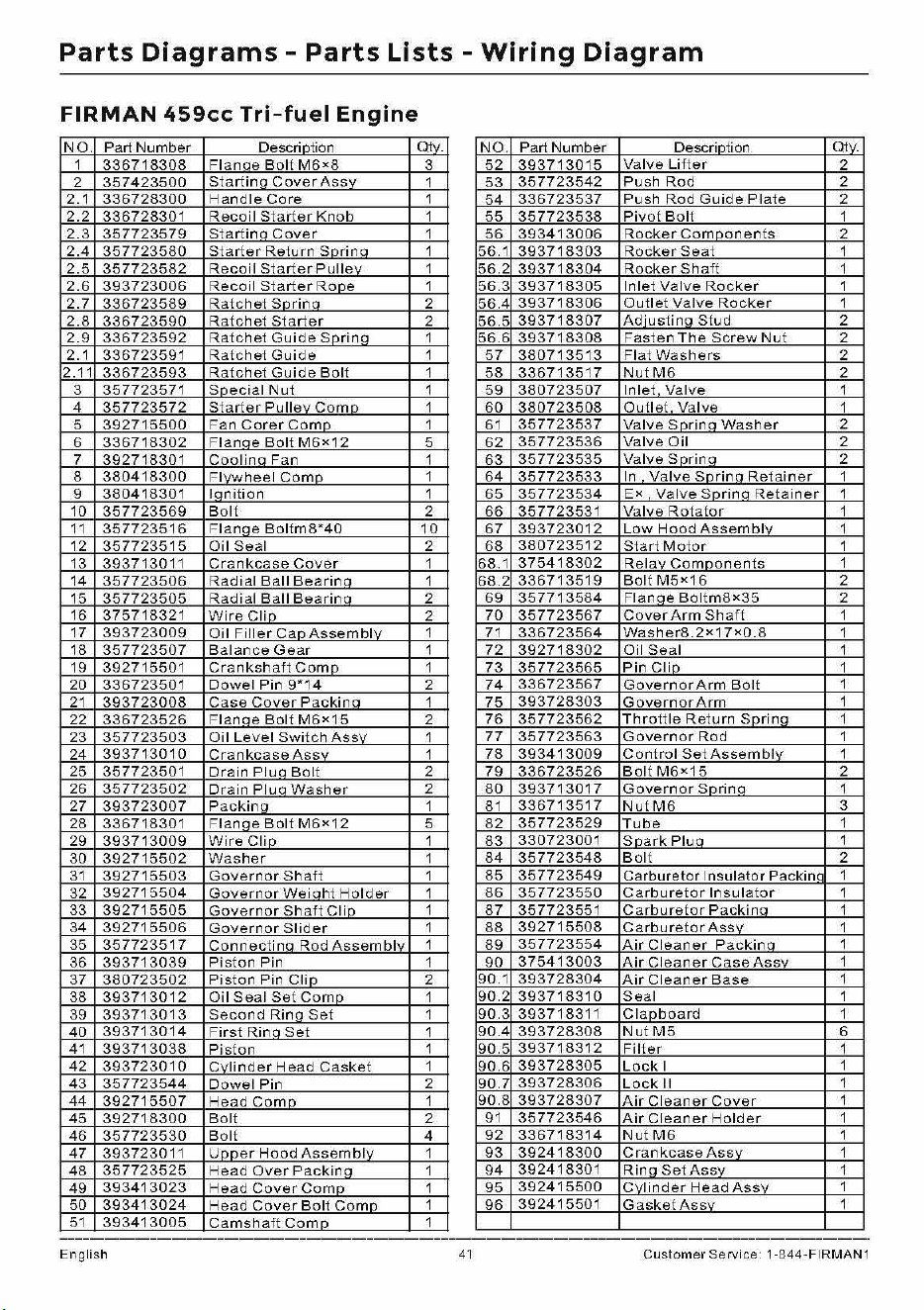
Parts
Diagrams
-
Parts
Lists -
Wiring
Diagram
FIRMAN
459cc
Tri-fuel
Engine
NO.
Part
Number
Desclintion
Qlv.
NO.
Part
Number
Descrintion
Qlv.
1
336718308
Fl
an
ne
Boll
M6
•8
3
52
3937
1
3015
Valve
Lifter
2
2
357423500
Startin
a
Cover
Assv
1
53
357723542
Push
Rod
2
2.1
336728300
Handle
Core
1
54
336723537
Push
Rod
Guide
Plate
2
2.2
336728301
Recoil
Starter
Knob
1
55
357723538
Pivot
Boll
1
2.3
357723579
Startina
Cover
1
56
3934
1
3006
Rocker
Comoonents
2
2.4
357723580
Starter
Return
Sorina
1
56.1
3937
1
8303
Rocker
Seal
1
2.5
357723582
Recoil
Starter
Pullev
1
56.2
3937
1
8304
Rocker
Sh
aft
1
2.6
393723006
Recoil
Starter
Rooe
1
56.3
3937
1
8305
In
let
Valve
Rocker
1
2.7
336723589
Ratchet
Sorin
a 2
56.4
3937
1
8306
Oull
et
Valve
Rocker
1
2.8
336723590
Ratchet
Starter
2
56.5
3937
1
8307
Adiustina
St
ud
2
2.9
336723592
Ratchet
Guide
Sprina
1
56.6
3937
1
8308
Fasten
The
Screw
Nut
2
2.1
336723591
Ratchet
Guide
1
57
3807
1
3513
Fia
l
Washers
2
2.11
336723593
Ratchet
Guide
Boll
1
58
3367
1
3517
NulM6
2
3
357723571
Snecial
Nut
1
59
380723507
Inlet
Valve
1
4
357723572
Starter
Pullev
Cornn
1
60
380723508
Ou
l l
et
Valve
1
5
392715500
Fan
Corer
Como
1 6 1
357723537
Valve
Sorino
Washer
2
6
336718302
Flanae
Bolt
M6•12
5
62
357723536
Valve
Oil
2
7
392718301
Coolino
Fan
1
63
357723535
Valve
Sorin
a 2
8
380418300
Fl,~heel
Como
1
64
357723533
In
Valve
Sorina
Retainer
1
9
380418301
lanilion
1
65
357723534
E•
Valve
Sorin
a
Retainer
1
10
357723569
Boll
2
66
357723531
Valve
Rotator
1
11
357723516
Flanae
Boltm8*40
10
67
393723012
Low
Hood
Assemblv
1
12
357723515
Oil
Seal
2
68
380723512
Start
Motor
1
13
393713011
Crankcase
Cover
1
68.1
3754
1
8302
Relav
Components
1
14
357723506
Radial
Ball
Bearinn
1
68.2
3367
1
3519
BollM5•16
2
15
357723505
Radial
Ball
Bearinn
2
69
3577
1
3584
Flanae
Bollm8•35
2
16
375718321
Wire
Clin
2
70
357723567
Cover
Arm
Sh
aft
1
17
393723009
Oil
FillerCanAssemblv
1 7 1
336723564
Washer8.2•17•0.8
1
18
357723507
Balance
Gear
1
72
3927
1
8302
Oil
Seal
1
19
392715501
Crankshaft
Como
1
73
357723565
Pin
Clio
1
20
336723501
Dowel
Pin
9"14
2
74
336723567
Governor
Arm
Boll
1
21
393723008
Case
Cover
Packina
1
75
393728303
Governor
Arm
1
22
336723526
Flanae
Boll
M6•15
2
76
357723562
Throttle
Return
Sorina
1
23
357723503
Oil
Level
Switch
Assv
1
77
357723563
Governor
Rod
1
24
393713010
Crankcase
Assv
1
78
3934
1
3009
Control
Set
Assemblv
1
25
357723501
Drain
Plua
Boll
2
79
336723526
Bolt
M6•15
2
26
357723502
Drain
Plua
Washer
2
80
3937
1
3017
Governor
Snrinn
1
27
393723007
Packina
1 8 1
3367
1
3517
NutM6
3
28
336718301
Flanae
Boll
M6•
12
5
82
357723529
Tube
1
29
393713009
Wire
Clip
1
83
330723001
Snark
Plun
1
30
392715502
Washer
1
84
357723548
Bolt
2
31
392715503
Governor
Shaft
1
85
357723549
Carburetor
Insulator
Packinn
1
32
392715504
GovernorWeinht
Holder
1
86
357723550
Carbure
t
or
Insula
t
or
1
33
392715505
Governor
Shaft
Clin
1
87
357723551
Carburetor
Packina
1
34
392715506
Governor
Slider
1
88
3927
1
5508
CarburetorAssv
1
35
357723517
Connectinn
Rod
Assemblv
1
89
357723554
Air
Cleaner
Packina
1
36
393713039
Piston
Pin
1
90
3754
1
3003
Air
Cleaner
Case
Assv
1
37
380723502
Piston
Pin
Clio
2
90.1
393728304
Air
Clean
er
Base
1
38
393713012
Oil
Seal
Set
Como
1
90.2
3937
1
8310
Seal
1
39
393713013
Second
Rina
Set
1
90.3
3937
18311
Clapboard
1
40
393713014
First
Rina
Set
1
90.4
393728308
NulM5
6
41
393713038
Piston
1
90.5
3937
1
8312
F
iller
1
42
393723010
CvlinderHead
Casket
1
90.6
393728305
Lock
I
1
43
357723544
Dowel
Pin
2
90.7
393728306
Lock
II
1
44
392715507
Head
Como
1
90.8
393728307
Air
Clean
er
Cover
1
45
392718300
Bolt
2
9 1
357723546
Air
Cleaner
Holder
1
46
357723530
Bolt
4
92
3367
1
8314
NulM6
1
47
393723011
Unner
Hood
Assembly
1
93
3924
1
8300
Crankcase
Assv
1
48
357723525
Head
Over
Packina
1
94
3924
1
8301
Rina
SetAssv
1
49
393413023
Head
Cover
Cornn
1
95
3924
1
5500
Cvlinder
Head
Assv
1
50
393413024
Head
Cover
Bolt
Cornn
1
96
3924
1
5501
GasketAssv
1
51
393413005
Camshaft
Como
1
English
41
Customer Service 1-844-FIRMAN1
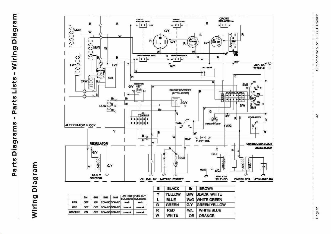
E
11:1
...
en
11:1
·-
a
en
C:
...
·-
~
I
II)
....
II)
·-
...I
II)
....
...
11:1
0.
I
II)
E
11:1
...
en
11:1
·-
a
II)
~I
E
11:1
...
en
11:1
·-
a
en
C:
...
i
.R
.'~-
ll~IM
IR
CIRCUIT
-
·--
+-U~W
l.@i'!'.
B
R
OROU
N
DT
(Q
TERMINAL.I
L
DCW
R ~LOCK y 1 1 1 1 "" IT
·~
1
rN
!
~11
OIL
LEVEL
fNI
BATTE
RV
STARTI:R
B BLACK
8M1
....
....
-
=~-~~L
1:!=~-=--
LJ>O
OFF
ON
~OM>IC
COM-NC
- -
OFF
OFF
OFF
bow-No
COM-NC
-
,.-
y
YELJ.OW
L BLUE
G GREEN
GABOLINE
ON
OFF
baMNc:
COM-NC
-
,.-
R RED
w WHITE
Br
B/W
WIG
GN
W/L
OR
;J
FUELCI.IT
SOLENOID
BROWN
BLACK WHITE
WHITE GREEN
GREEN YELLOW
WHITE BLUE
ORANGE
Bl
B
CON1RDLBQXBLOCK I
ENGINE
BLOCK
I
IGNITION COIL SPARKINQ
PLU1
z
<(
::;
Q;
LL
.,.
..,.
"?
N
..,.
~
O>
c;
UJ
Service
-
Warranty
For
service
information
contact
FRI
MAN
customer
service
at
l-844-347-6261
or
at
www.firmanpowerequipment.com
to
obtain
warranty
service
information
or
to
order
re
placement
parts
or
accessories.
HOW
TO
ORDER
REPLACEMENT
PARTS
Even
quality-bui
It
equipment
such
as
this
electric
genera
tor
may
need
occa
siona
I
replacement
parts
to
maintain
it
in
good
condition
overt
he
years.
To
order
replacement
parts,
please
give
the
following
information,
e
Model
No.
Rev.
Level
and
Serial
No.
found
on
the
Data
Decal.
e
Parts
num
beror
numbers
as
shown
in
the
Parts
List
section.
• A
brief
description
of
the
trouble
with
the
generator.
FIRMAN
4 Years
Limited
Warranty
Warranty
Qualifications
Register
your
product
using
the
QR
code
provided
or
at
www.firmanpowerequipment.com.
Fl
RMAN
wi
II
also
register
the
warranty
upon
receipt
of
your
Warranty
Registration
Card
and
a
copy
of
your
sales
receipt
from
one
of
FIRMAN's
retail
locations
as
proof
of
purchase.
Please
submit
your
warranty
registration
and
your
proof
of
purchase
with
in
ten(l0)
days
of
the
date
of
purchase.
Repair/Replacement
Warranty
FIRMAN
warrants
to
the
original
purchaser
that
the
mechanical
and
electrical
components
will
be
free
of
defects
in
material
and
workmanship
for
a
period
of
one
(1)
year(parts
and
labor)
and
4 years
(parts
and
technical
support)
from
the
original
date
of
purchase
90
days
[parts
and
labor]
and
180 days [parts]
for
commercial
&
industrial
use.
Transportation
charges
on
product
submitted
for
repair
or
replacement
under
this
warranty
are
the
sole
responsibility
of
the
purchaser.
This
warranty
only
applies
to
the
original
purchaser
and is
not
transferable.
Do
Not
Return
the
Unit
to
the
Place
of
Purchase
Contact
the
FIRMAN
customer
service
and
FIRMAN
will
troubleshoot
any
issue
via
phone
or
e-mail.
If
the
problem
is
not
corrected
by
this
method,
FIRMAN
will,
at
its
option,
authorize
evaluation,
repair
or
replacement
of
the
defective
part
or
component
at
a
FIRMAN
Service
Center.
Fl
RMAN
wi
II
provide
you
with
a
case
number
forwa
rranty
service.
Please
keep
it
for
future
reference.
Repairs
or
replacements
without
prior
authorization,
or
at
an
unauthorized
repair
facility,
wi
II
not
be
covered
by
this
warranty.
Warranty
Exclusions
This
warranty
does
not
cover
the
following
repairs
and
equipment.
Normal
Wear
Your
product
needs
periodic
parts
and
service
to
perform
well.
Th
is
warranty
does
not
cover
repair
when
normal
use
has
exhausted
the
life
ofa
part
or
the
equipment
as
a
whole.
English
43
Customer
Service: 1-844-FIRMAN1
Service
-
Warranty
Installation,
Use
and
Maintenance
This
warranty
will
not
apply
to
parts
and/or
labor
if
your
product
is
deemed
to
have
been
misused,
neglected,
involved
in
an
accident,
abused,
loaded
beyond
the
generator's
limits,
modified,
installed
improperly
or
connected
incorrectly
to
any
electrical
component.
Normal
maintenance
is
not
covered
by
this
warranty.
Other
Exclusions
Th
is
warranty
excludes,
-
cosmetic
defects
such
as
paint,
decals,
etc.
-wear
items
-
accessory
parts
-
failures
due
to
acts
of
God
and
other
force
majeure
events
beyond
the
manufacturer's
control
-
problems
caused
by
parts
that
are
not
original
FIRMAN
parts
-
units
used
for
prime
power
in
place
of
existing
utility
powerwhere
utility
is
present
or
in
place
of
utility
powerwhere
utility
power
service
does
not
normally
exist.
Limits
of
Implied
Warranty
and
Consequential
Damage
FIRMAN
disclaims
any
obligation
to
cover
any
loss
of
time,
use
of
this
product,
freight,
or
any
incidental
or
consequential
claim
by
anyone
from
using
this
product.
THIS
WARRANTY
IS
IN
LIEU
OF
ALL OTHER WARRANTIES, EXPRESS
OR
IMPLIED,
INCLUDING
WARRANTIES OF
MERCHANT
ABLILITY
OR FITNESS FOR A PARTICULAR PURPOSE.
Aun
it
provided
as
an
exchange
wi
II
be
subject
to
the
warranty
of
the
original
unit.
The
length
of
the
warranty
governing
the
exchanged
unit
will
remain
calculated
by
reference
to
the
purchase
date
of
the
original
unit.
This
warranty
gives
you
certain
legal
rights
which
may
change
from
state
to
state.
Your
state
may
also
have
other
rights
you
may
be
entitled
to
that
a re
not
listed
within
this
warranty.
Contact
Information
You
may
contact
FIRMAN
at:
Address
Firman
Power
Equipment
Inc.
Attn,
Customer
Service
8644
W.
Ludlow
Dr.
Peoria,
AZ
85381
www.firmanpowerequipment.com
We
are
FIRMAN
POWER
-And
we
are
here
for
you.
English 44
Customer
Service 1-844-FIRMAN1
Service
-
Warranty
FIRMAN
POWER
EQUIPMENT
INC.
Emission
Control
System
Warranty
CALIFORNIA
AND
FEDERAL EXHAUST
AND
EVAPORATIVE EMISSIONS CONTROL
WARRANTY
STATEMENT
YOUR
WARRANTY
RIGHTS
AND
OBLIGATIONS
The
California
Air
Resources Board, US Environmental Protection
Agency
("US EPA") and FIRMAN
POWER
EQUIPMENT
INC.(FIRMAN)
are
pleased
to
explain
the
emissions control
systems
warranty
on
your
2022-2023
or
later
Small Off-Road
Engine
("SORE") and
engine
powered equipment.
In
California, new equipment
that
use
small off-road engines
must
be
designed,
built
and
equipped
to
meet
the
State's
stringent
anti-smog
standards.
FIRMAN
must
warrant
the
emissions
control
systems on
your
SORE and engine powered equipment
for
the periods
of
time
listed below provided
there
has
been no abuse,
neglect
or
improper
maintenance
of
your
small off-road engine
or
equipment leading
to
the
failure
of
the
emissions control system.
Your
emissions
control
system
may
include
parts
such
as
the
carburetor
or
fuel-injection
system,
the
ignition
system
,
catalytic
converter,
fuel
tanks,
fuel
lines
(for
liquid
fuel
and
fuel
vapors),
fuel
caps,
valves,
canisters, filters,
clamps
and
other
associated
components.
Also
included
may
be
hoses,
belts,
connectors,
and
other
emission-related
assemblies.
Where
a
warrantable
condition
exists,
FIRMAN
will
repair
your
SORE
and
engine
powered
equipment
at
no
cost
to
you
including
diagnosis,
parts
and
labor
MANUFACTURER'S
WARRANTY
COVERAGE:
The exhaust and
evaporative
emissions
control
system
on
your
small
off-road
engine
and
engine
powered
equipment
is warrant
ed
for
two
years.
1f
any
emissions-related
part
on
your
small
off-road
engine
and
engine
powered
equipment
is
defec
t ive, t he
part
will
be
repaired
or
replaced
by
FJRMAN.
OWNER'S
WARRANTY
RESPONSIBILITIES:
As
the
SORE
and
engine
powered
equipment
own er,
you
are
responsible
for
the
performance
of
the
required
maintenance
listed
in
your
operator's
manual.
FIRMAN
recommends
that
you
retain
all receipts
cov
e
ring
maintenance
on
your
SO
RE
and
engine
powered
equipment,
but
FIRMAN
cannot
deny
warranty
coverage
solely
fort
he
lack
of
receipts
orfor
your
failure
to
ensure
the
perform
a nee
of
a II
scheduled
maintenance.
As
the
SORE
and
engine
powered
equipment
owner,
you
should
however
be
aware
that
FIRMAN
may
deny
you
warrant y
coverage
if
your
small
off-road
engine
or
engine
powered
equipment
or
a
part
has fa
iled
due
to
abuse,
neglect,
or
improper
maintenance
or
unapproved
modifications.
You
are
responsible
for
presenting
your
small
off-road
engine
and
engine
powered
equipment
to
a FIRMAN dist
ribution
center
or
service
center
as
soon
as
th
e
problem
e)(ists. The
warranty
repairs shall
be
completed
in
a reasonable
amoun
t
of
time,
not
to
exceed
30 days.
If
you
have
any
questions
regarding
your
warranty
rights
and
responsibilities,
you
should
contact
FIRMAN
at
1-8
4
4-347-6261
.
FIRMAN Emission Control Defects
Warranty
Provisions
The warranty period begins
on
the
date the
engine/equipment
is
delivered
to
an
ultimate
purchaser. FIRMAN warrants
to
th
e
ultimate
purchaser and each subsequent purchaser
that
the
engine is:
Designed,
built,
and
equipped
so
as
to
conform
with
all
applicable
r
egula
t
ions
adopted
by
the
Air
Resources Board and
US
EPA;
and
Free
from
defects
in
materials and
workmanship
th
at cause
the
failure
of
a
warranted
part
to
be
identical
in
all
material
respects
to
the
part
as
described
in
the
engine
manufacturers
application
for
certification.
The
warranty
on
emissions-related parts
is:
as:
follows::
{1)
Any
warranted
part
that
is
not
scheduled
for
replacement
as
required
maintenance
in
the
owner's
manual
supplied,
is
warranted
for
the
warranty
period
stated above.
Jf
any
such
part
fails
during
the
period
of
warranty
coverage,
the
part
will
be
repaired
or
replaced
by
FIRMAN
at
no
charge
to
the
owner.
Any
such
part
repaired
or
replaced
under
the
warranty
will
be
w
arranted
for
the
remaining
warr
a
nty
period.
{2)
Any
warranted
part
that
is sche
duled
only
for
regular
inspection
in
the
owner's
manual s
upplied,
is
warranted
for
the
war
ra
nty
period
stated above.
Any
such
part
repaired
or
replaced
under
warra
ntywill
be
warranted
fort
he
remaining
warranty
period.
{3)
Any
warrant
ed
part
that
is
scheduled
for
replacement
as
required
maintenanc
e
in
the
owner's
manual
supplied,
is
warranted
for
the
period
of
time
prior
to
the
first
scheduled
replacement
poin
t
for
that
part.
If
the
part
fails
prior
to
the
first
scheduled
replacement
,
the
part
will
be
repaired
or
replaced
by
FJRMAN
at
no
charge
to
the
owner.
Any
such
part
repaired
or
replaced
under
warranty
will
be
warranted
for
the
remainder
of
the
period
prior
to
the
first
scheduled
replacement
point
fort
he
pa
rt.
(4)
Repair
or
replacement
of
any
warranted
part
under
the
warranty
mu
st
be
perform
ed at
no
charge
to
the
owner
at
a
warranty
station.
(
S)
Notwithstanding
the
provisions
of
Subsection (4) above,
warranty
services
or
repairs
must
be
provided
by
FIRMAN t
hat
are franchised t o service
the
subject
engines.
(6)The
owner
must
not
be
charged
for
diagnos
t
ic
labor
t
hat
leads
to
the
determina
t
ion
that
a
warranted
part
is
in
fact
defective
,
provided
that
such
diagnostic
work
is
performed
at
a
warranty
station.
(7) FJRMAN is
liable
for
damages
to
other
engine
components
pro)(imately
caused
by
a
failure
under
warranty
of
any
warranted
part.
English 45
Customer
Service 1-844-FIRMAN1
Service
-
Warranty
(8)
Throughout
the
emissions
warranty
period
de
f
ined
in
Subsection (b)(2), FIRMAN
will
main
tain a
supply
of
warranted
parts
sufficient
to
meet
the
e)(pected
demand
for
such
parts.
(9)
Any
replacement
pa
rt
may
be
used
in
the
performa
nee
of
any
warranty
main
t enance
or
repairs and
must
be
provided
without
charge
to
the
owner.
Such
use
will
not
reduce
the
warranty
obligations
of
the
manufacturer.
(10)
Add-on
or
modified
parts
that
are
not
exempted
by
the
Air
Resources Board may
not
be used. The use
of
any
non-exempted
add-on
or
modified
parts
by
the
ultimate
purchaser
will
be
grounds
ford
isallowing a
warranty
claim.
The
manufac
t
urer
will
not
be
liable
to
warrant
failures
of
warranted
parts
caused
by
the
use
of
a non-e)(empted add -
on
or
modified
part.
PARTS
COVERED
BY
WARRANTY
Listed
below
are
the
parts
{if
equipped)
covered
by
the
Federal and California Emission
Control
System
Warranty,
1.lgnition
system
including:
- Spark plug
- I
gnition
coil
2. Fuel
metering
system:
- Fuel tank
- Fuel cap
-
fuel
lines
(for
liquid
fuel
and
fuel
vapors) and
related
fittings/damps
- Fuel
regulator,
carburetor
and
internal
parts.
3. Catalytic
muffler
assembly
including:
- Exhaust
manifold
-
Catalytic
conver
t er
-
Muffler
gasket
-pulse valve
Limitations
4.
Air
induction
system
including:
-
lnta
ke
pipe/manifold
-
Air
cleaner
5. Crankcase
breather
assembly
including:
- Bre
ather
connection
tu
be
6. Fuel
tank
evaporative
emission
control
system
including:
- Purge valves
- Carbon canist er
-
Vapor
hoses and
fitting/damps
This Emission
Control
System
Warranty
sha II
not
cover
any
of
the
following:
(a}
Consequential
damages such
as
loss
oftime,
inconvenience
, loss
of
use
of
the
engine
or
equipment,
etc.
(b) Diagnosis
and
inspection
fees
that
do
not
result
in
eligible
warranty
service
being
performed.
FIRMAN
POWER
EQUIPMENT
INC.
www.fi
rma
npowe
req
u ip
me
nt.co
m
English 46
Customer
Service 1-844-FIRMAN1

FOLLOW
US
ON
SOCIAL
USE
#EVE
RVC
ENE
RATO
RTE
L
LSASTO
RV™
FOR
YOUR
CHANCE
TO
WIN
FIRMAN
SWAC
l!J
Ii
D
rJ
FIRMAN
POWER
EQUIPMENT
INC
.
8644
W.
LUDLOW
DR.
PEORIA
,
AZ
85381
1-
844
-
347
-6261
WWW.FIRMANPOWEREQUIPMENT.COM
All
r i
gh
l5
r
es
erv e
d.
Any
reprinting
or
unauthor
iz
ed
u se
wi
t
hout
th e
wr
i
tten
perm
i
ss
ion
is
expr
e ss ly
prohibi
t
ed
.
P/N,39374547
1
Rev,00