OPERATOR’S MANUAL
Record product information to reference when ordering parts or
obtaining warranty coverage.
GASOLINE PORTABLE GENERATOR
MODEL NUMBER
P 1 2 0 0 1
Rev Level:00
P/N:399745593 Rev:00
•
DO
NOT
RETURN
TOSTORE!
l
I
CALL
US
FIRST -
'I
1
1-844-347-6261
/J/_j
FOR
QUESTIONS
OR SERVICE INFORMATION
c~
lntertek
5001841
SERIAL NUMBER:
PURCHASE DATE:

Table of Contents
Introduction . . . . . . . . . . . .
Features and Controls . . . . . . . . . . . . . . . . . . . . . . . . . . . . . . . . . . . . . . . . . . . . . . . . . . . . . . . . . . . . . . . 5
Operation . . . . . . . . . . . . . . . . . . . . . . . . . . . . . . . . . . . . . . . . . . . . . . . . . . . . . . . . . . . . . . . . . . . . . . . . . . . 1 0
Maintenance - Storage. . . . . . . . . . . . . . . . . . . . . . . . . . . . . . . . . . . . . . . . . . . . . . . . . . . . . . . . . . . . . . 2 0
Troubleshooting- Specifications . . . . . . . . . . . . . . . . . . . . . . . . . . . . . . . . . . . . . . . . . . . . . . . . . . . . 28
Parts Diagrams - Parts Lists - Wiring Diagram . . . . . . . . . . . . . . . . . . . . . . . . . . . . . . . . . . . . . . . 29
Service - Warranty. . . . . . . . . . . . . . . . . . . . . . . . . . . . . . . . . . . . . . . . . . . . . . . . . . . . . . . . . . . . . . . . . . .36
. . . . . . . . . . . . . . . . . . . . . . . . . . . . . . . . . . . . . . . . . . . . . . . . . . . . . . . . . . . . .1
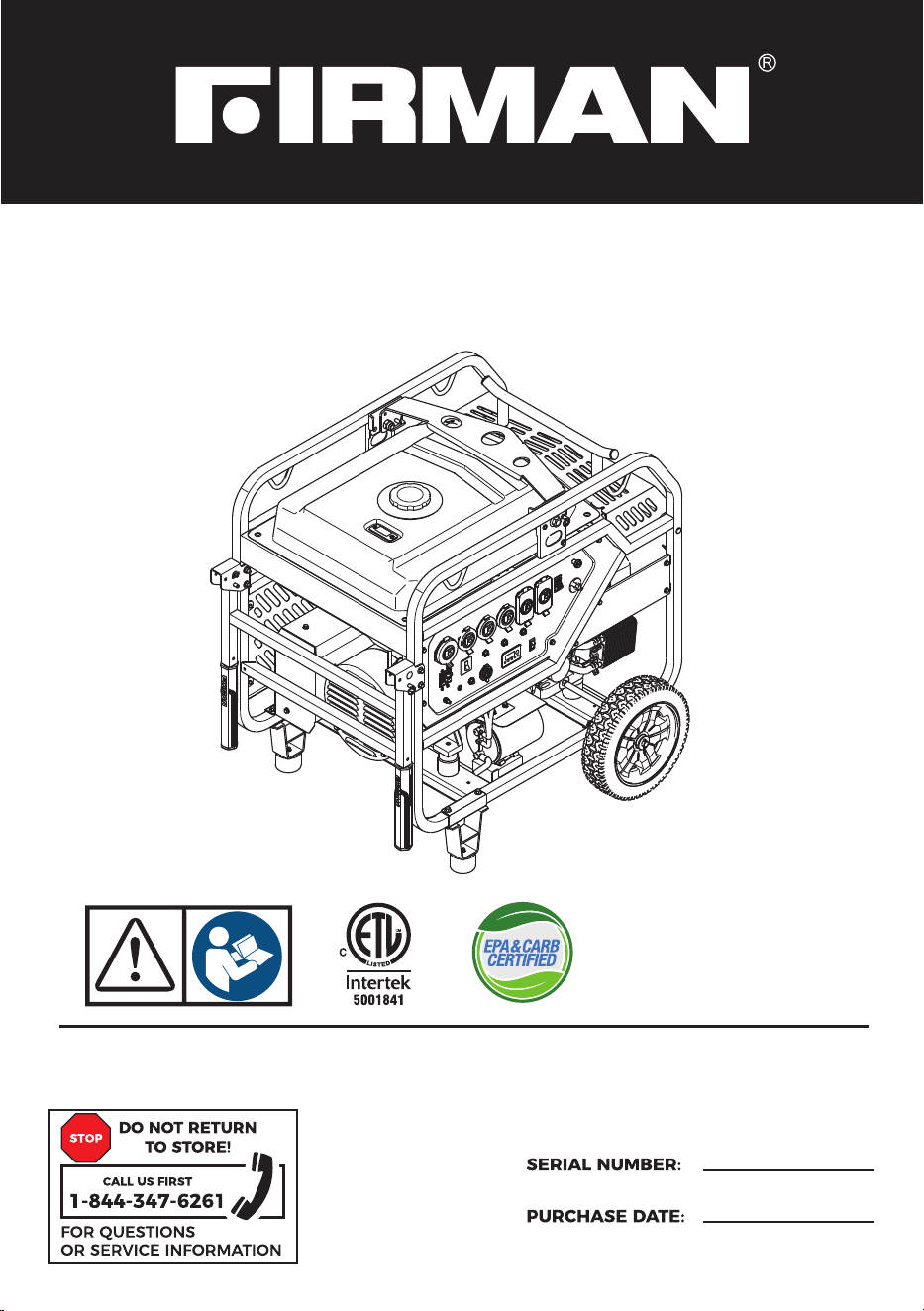
REGISTER YOUR PRODUCT
Register your Firman generator online at www.firmanpowerequipment.com
INTRODUCTION
Thank you for purchasing a FIRMAN generator. You have selected a high-quality, precision engineered
generator set designed and tested to give you years of satisfactory service. This generator is designed
to run only on unleaded gasoline. This generator is not intended to be run unattended or to supply
power to life safety support.
This manual contains safety information to make you aware of the hazards and risks associated
with generator products and how to avoid them. This generator is designed and intended only
for supplying electrical power for operating compatible electrical lighting, appliances, tools and
motor loads, and is not intended for any other purpose. It is important that you read and
understand these instructions thoroughly before attempting to start or operate this portable
generator. Save these original instructions for future reference.
All information in this publication is based on the latest production information available at the
time of approval for printing. The manufacturer reserves the right to change, alter or otherwise
improve the generator and this documentation at any time without prior notice.
INTRODUCTION
01
02
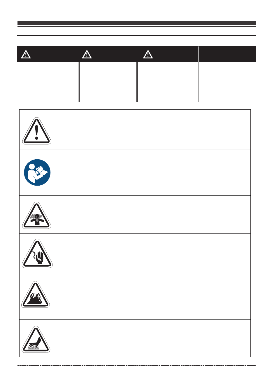
SIGNAL WORDS
DANGER WARNING CAUTION
Indicates a hazard
which, if not avoided,
will result in death or
serious injury.
Indicates a hazard
which, if not avoided,
could result in death
or serious injury.
Indicates a hazard
which, if not avoided,
could result in minor or
moderate injury.
Toxic Fumes- Engine exhaust contains carbon monoxide, a
poisonous gas that will kill you in minutes. You cannot smell
it or see it.
Fire- Fuel and its vapors are extremely flammable which could
cause burns or fire resulting in death or serious injury.Engine
exhaust could cause fire resulting in death or serious injury.
Hot Surface- Muffler could cause burns resulting in serious injury.
Generator could cause electrical shock resulting in death or serious
injury.
Safety Alert Symbol- Indicates a potential personal injury hazard.
Operator's Manual- Failure to follow warnings, instructions and
operator's manual could result in death or serious injury.
English Customer Service: 1-844-FIRMAN1
NOTICE
Indicates information
considered Important,
but not hazard-related.
INTRODUCTION
English Customer Service: 1-844-FIRMAN1
WARNING! This product can expose you to chemicals including gasoline engine
exhaust, which is known to the State of California to cause cancer, and carbon
monoxide, which is known to the State of California to cause birth defects or other
reproductive harm. For more information go to www.P65Warnings.ca.gov.
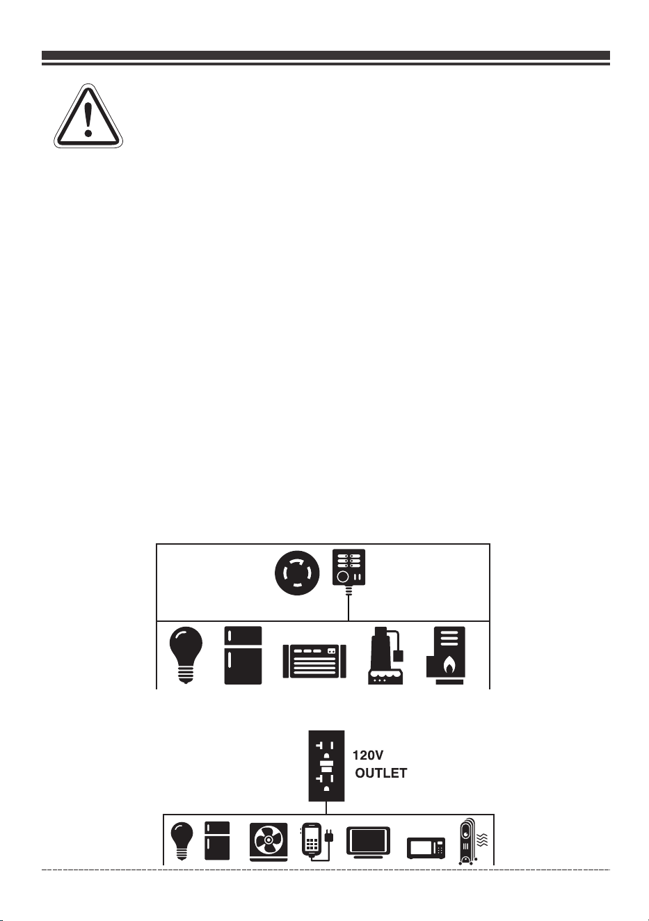
This outdoor generator can be used to power outdoor items using extension cords or to restore
home power using a transfer switch. A transfer switch is a separate device installed by a licensed
electrician that allows the portable generator to be cord connected, using either of the 120/240V
receptacles, directly into your home’s electrical system. Install a listed transfer switch as soon as
possible if this generator will be used to restore power to your home.
NOTICE If you have questions about intended use, contact customer service. This portable
generator is designed to be used only with FIRMAN authorized parts.
FIRMAN
The generator has a system ground that connects the generator frame components to the ground
terminals on the AC output receptacles. The system ground is connected to the AC neutral wire.
The neutral is bonded to the generator frame.
System Ground
There may be Federal or State regulations, local codes, or ordinances that apply to the intended
use of the generator. Consult a qualified electrician, electrical inspector, or the local agency
having jurisdiction. This generator is not intended to be used at a construction site or similar
activity as defined by NFPA 70-2020 (NEC) section 590.6.
Compliance Requirements
Connections to your home’s electrical system must use a listed* transfer switch installed by a
licensed electrician. The connection must isolate the generator power from the utility power and
comply with all applicable laws and electrical codes.
To Restore Home Power Using a Listed Transfer Switch
Typical
120/240V
Outlet
Transfer
Switch
Typical Indoor Items
To Restore Power Using Extension Cords
03
INTRODUCTION
••
r
120V
OUTLET
English Customer Service: 1-844-FIRMAN1
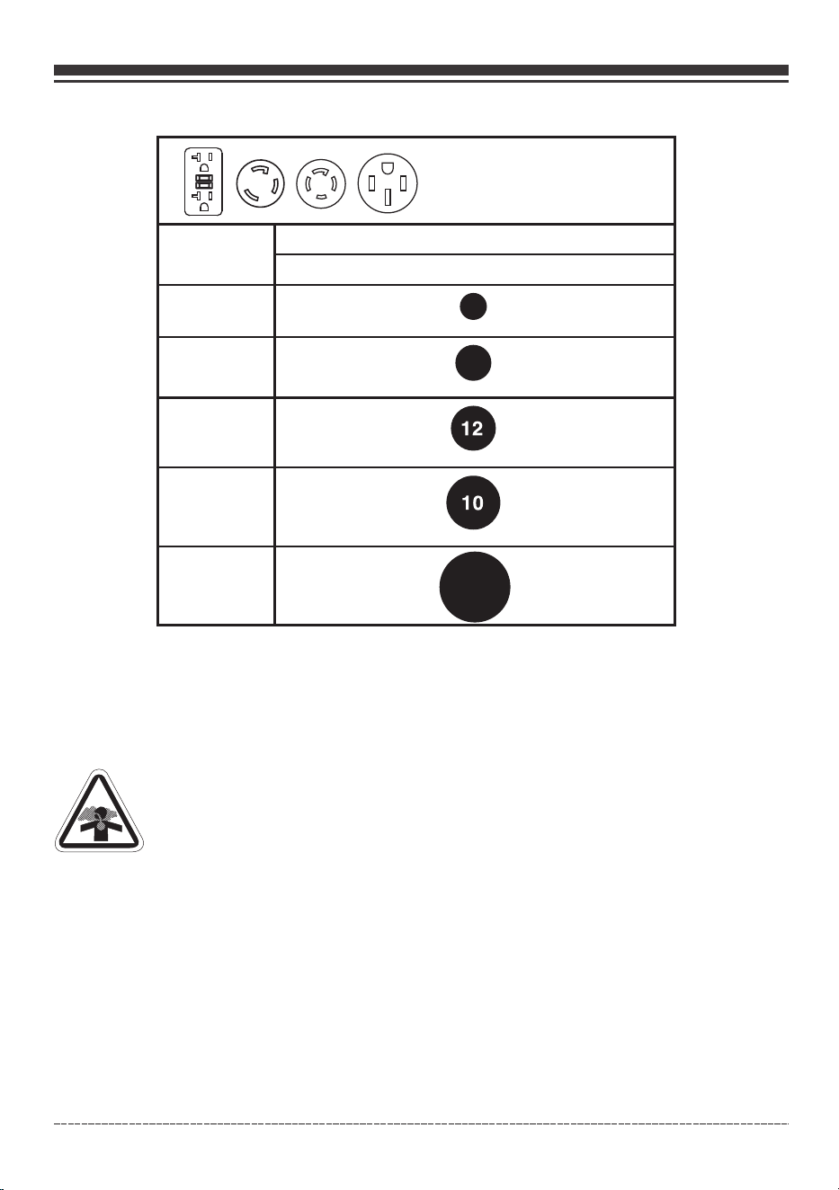
1. Only use grounded cords marked for outdoor use rated for your loads.
16
14
To provide power using
extension cords
Total
Amperage
Minimum Gauge, Outdoor Rated
Up to 50 FT (15m)
Up to 13A
Up to 15A
Up to 20A
Up to 30A
Up to 50A
2. Follow cord safety instructions.
3. Install carbon monoxide alarm(s).
4. When operating portable generator with extension cords, make sure portable generator is located
in an open, outdoor area, at least 20 ft. (6 m.) from occupied spaces with exhaust pointed away.
5. Extension cords running directly into your home, powering indoor items IS NOT RECOMMENDED.
Extension cords running directly into the home increase your risk of carbon monoxide
poisoning through any openings.
If an extension cord running directly into your home is used to power indoor items, the
operator recognizes that this increases the risk of CO poisoning to people inside the home
and assumes that risk.
•
•
6. Install a listed *transfer switch as soon as possible if this or any generator will be used to restore
power to your home.
*
product safety test standards.
Certified by a Nationally Recognized Testing Laboratory that the product complies to appropriate
DANGER! Engine exhaust contains carbon monoxide, a poisonous gas that will kill
you in minutes. You cannot smell it, see it, or taste it. Even if you do not smell exhaust
fumes, you could still be exposed to carbon monoxide gas.
04
6
INTRODUCTION
•
•
English Customer Service: 1-844-FIRMAN1
*We are always working to improve our products. Therefore, the enclosed product may differ
slightly from the image on this page.
05
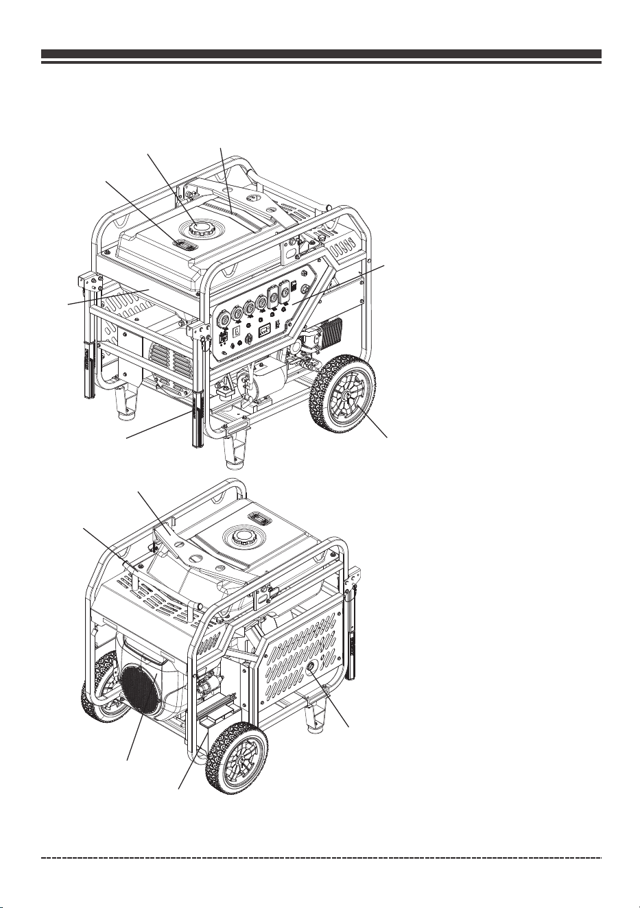
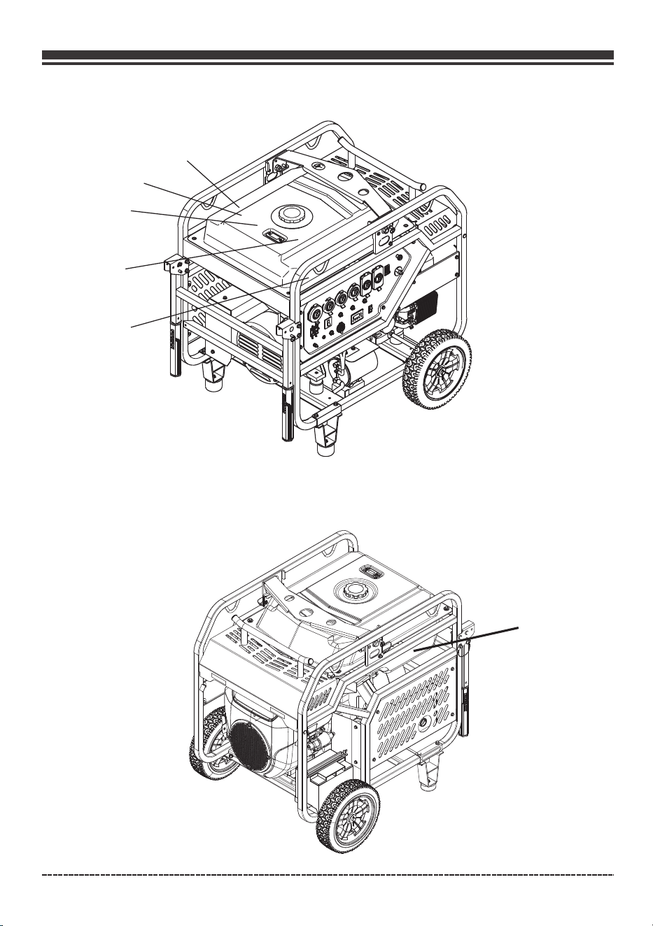
FEATURES AND CONTROLS
1-
2-
3-
4-
5-
6-
7-
8- Lifting Hook
13.3 Gallon(50.2L) Capacity
Fuel Tank
Fuel Cap
Fuel Gauge
12.0"(30.5cm) Flat Free
Wheel
Control Panel
760cc V-TWIN Engine
Muffler & Spark Arrester
9- Handle
10-Power Cord Holder &
Maintance cover handle
11- Battery
12- Data decal/ serial number
1
①
②
③
④
⑤
⑥
⑦
⑧
⑨
⑩
⑪
○
12
English Customer Service: 1-844-FIRMAN1
06
FEATURES AND CONTROLS
①
1
②
③
④
⑤
⑥⑦⑧⑨
English Customer Service: 1-844-FIRMAN1
07
FEATURES AND CONTROLS
CD
A DANCER A PELICRO A DANCER
Utiliser
un
g8n9rateur
a l'int8rieur
PEUT
VOUS
TUER
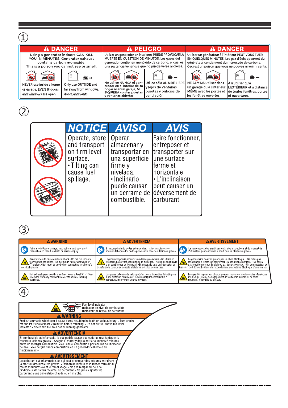
Using a
generator
indoors
CAN KILL
YOU
IN
MINUTES. Generator
exhaust
contains
carbon
monoxide.
This
is
a
poison
you
cannot
see
or
smell.
Utilizar
un
generador
en
interiores
PU
EDE
PROVOCARLA
MUERTE
EN
CUESTION
DE
MINUTOS.
Los
gases
del
generador
contienen
mon6xido
de
carbono,
el
cual
es
una
sustancia
venenosa
que
no
puede
verse
ni
olerse.
EN
QUELQUES
MINUTES.
Les
gaz
d'9chappement
du
generateur
contiennent
du
monoxyde
de
carbone.
Ceci
est
un
poison
que
vous
ne
pouvez
ni
voir
ni
sentir.
lit
~
i:r ...
lit~
i:{
...
NE
JAMAIS utiliser dans A n'utiliser
qu•a
NEVER
use
inside a
home
Only
use
OUTSIDE
and
or
garage,
EVEN
IF
doors
far
away
from
windows,
and
windows
are
open.
doors.and
vents.
No utilice NUNCA
el
gen-
erador en
el
interior
de
su
hogar ni enun garaje,
NI
SIQUIERA
con
las
puertas
y ventanas abiertas.
Utilice s6Io AL
AIRE
LIBRE
y lejos
de
ventanas,
puertas
y
orificios
de
ventilaci6n.
un garage ou a l'intE!rieur,
L'EXT~RIEUR
et
a distance
ME.ME
avec les portes
et
de toutes fenetres, portes
les fenetres ouvertes.
et
ouvertures.
NOTICE AV/SO AVIS
Operate,
store
and
transport
on
firm
level
surface.
•
Tilting
can
cause
fuel
spillage.
Operar,
almacenar
y
transportar
en
una
superficie
firme
y
nivelada.
•
lnclinarlo
Faire
fonctionner,
entreposer
et
transporter
sur
une
surface
ferme
et
horizontale.
•
L'inclinaison
puede
causar
peut
causer
un
un
derrame
de
deversement
de
combustible.
carburant.
I
tft.
Failuretofollowwarnings,instructionsandoperator's
\ij/
manual
could
result
in
death
or
serious
injury.
tft.
El
incumplimiento
de
las
advertencias,
las
instrucciones
y
el
tft.
Le
non-respect
des
avertissements,
des
instructions
et
du
manuel
de
\
\ij/
manual
del
operador
podria
provocar
la
muerte
o
lesiones
graves.
\ij/
l'ut1lisateur
peutentrainer
la
mort
ou
des
blessures
graves.
&
Generatorcouldcauseelectricalshock.•Donotrunindoors
to
avoid
wet
conditions.
·Do
not
run
in
rain
or
wet
weather.
•Transfer
switch
must
be
used
when
connecting
to
a
home's
electrical
system.
A
~J~~~~g:r~~~fc~~~r~~:
~:s~~~!i~~~~riNcg-~~~e~i~~
~a
A
~n~~i~r;!~iiel'~~;:tl;~~~~i~~rul~;~~~j~~~:!q~im·idNe~~i~:
~~fes
:'
£!lo
en
condiciones
de
humedad.
•Es
necesario
usar
un
interruptor
de
~
pas
fonctionner
sous
la
pluie
ou
par
temps
pluvieux.
•
Un
commutateur
de
transferenciacuandoseconeclaalsistemaeli:lclricodeunacasa.
transfertdoit6treutilistilorsduraccordementausyslemeeIectriqued'unemaison.
£
Hotexhaustgasescouldcausafires.Keepatleast5ft.(1.5m)
clearancefromanycombustiblesorstructures,incluing
overhead.
£~
Fuel
level
indicator
~
~
lndicador
de
nivel
de
combustible
lndicateur
de
niveau
de
carburant
A
Fuel
is
flammable
which
could
cause
burns
resulting
in
death
or
serious
injury.•
Turn
engin,e/
off
and
let
it
cool
at
least
2
minutes
before
refueling.
•DO
not
fill
fuel
above
fuel
level
indicator.•
Never
add
fuel
to
a
hot
or running
generator.
antes
de
recargar
combustible
.•
No
Ilene
el
combustible
por
encima
del
indicador
El
combustible
es
inflamable,
lo
que
podria
causar
quemaduras
resultantes
en
It/
muerte
o
lesiones
graves
.•
Apague
el
motory
d~jelo
enfriar
al
menos
2
minutos
de
nivel.
0
No
cargue
nunca
combustible
en
un
generador
caliente
o
en
funcionamiento.
I
Le
carburant
est
inflammable,
ce
qyi
peut
provoquer
des
brillures
entrainany
la
mart
ou
des
blessures
graves
.•
Eteindre
le
moteur
et
le
laisser
refroidir
au
mains
2
minutes
avant
le
remplissage
.•
Ne
pas
remplir
au-delB.
de
l'indicateur
de
niveau
maximal
de
carburant..
Ne
jamais
ajouter
de
carburant
a
une
g~n~ratrice
chaude
ou
en
marche.
I
English Customer Service: 1-844-FIRMAN1
08
FEATURES AND CONTROLS
⑥
⑦
⑧
⑨
0
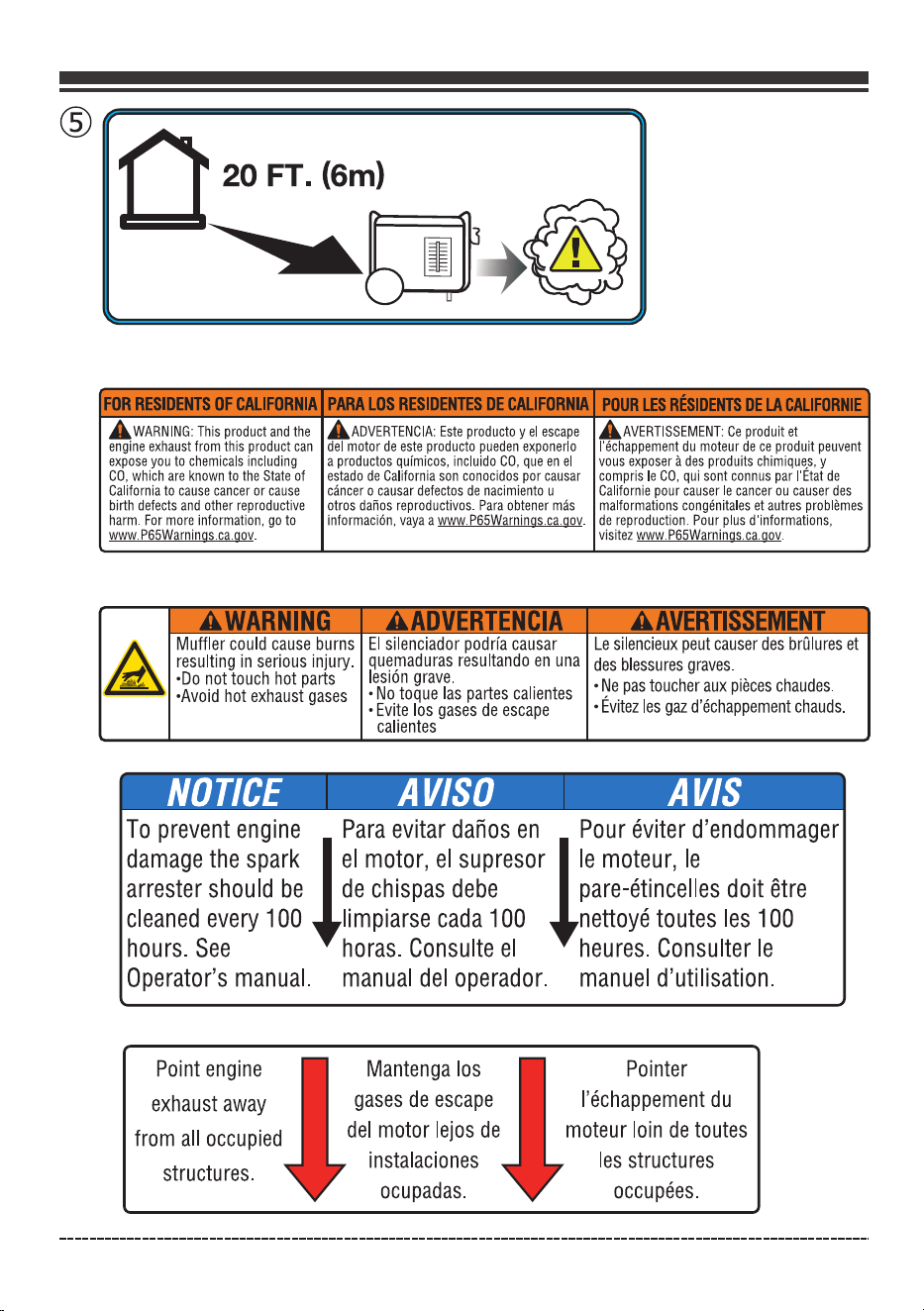
20FT.(6m)
~~
FOR
RESIDENTS
OF
r.AUFORJIA
PARA
LOS
RESIDENTES
DE
r.ALFORNIA
POOR
LES
IEIIIIENIS
DE
LA
l'.ALFORNIE
AwARNING:
This
product
and
the
AA
□
VERTENCIA:
Este
product
□
y
el
escape
AAVERTISSEMENT:
Ce
produit
et
engine
exhaust
from
this
product
can
del
motor
de
este
product
□
pueden
exponerlo
l'echappement
du
moteur
de
ce
produit
peuvent
expose
you
to
chemicals
including
a
productos
qufmicos,
incluido
CO,
queen
el
vous
exposer
a
des
produits
chimique,s,
y
CO,
which
are
known
to
the
State
of
estado
de
California
son
conocidos
par
causar
compris
le
CO,
qui
sont
conn
us
par
l'Etat
de
California
to
cause
cancer
or
cause
cancer
o
causar
defectos
de
nacimiento
u
Californie
pour
causer
le
cancer
ou
causer
des
birth
defects
and
other
reproductive
otros
daiios
reproductivos.
Para
obtener
mas
malformations
congenitales
et
autres
problemes
harm.
For
more
information,
go
to
informaci6n,
vaya
a
www
P65Warnings
ca.gov.
de
reproduction.
Pour
plus
d'informations,
www
P65Waroiogs
ca.gov.
visitez
www
P65Waroings
ca.gov.
.A.WARNING
AADVERTENCIA
AAVERTlssEMENT
£
Muffler
could
cause
burns
El
silenciador
podrfa
causar
Le
silencieux
peut
causer
des
br
□
lures
et
resulting
in
serious
injury.
quemaduras
resultando
en
una
des
blessures
graves.
•Do
not
touch
hot
parts
lesion
grave.
•
Ne
pas
toucher
aux
pieces
chaudes.
•Avoid
hot
exhaust
gases
•
No
toque
las
partes
calientes
•
Evitez
les
gaz
d'echappement
chauds.
•
Evite
las
gases
de
escape
calientes
NOTICE
AV/SO
AVIS
To
prevent
engine
!Para
evitar
danos
en
!Pour
eviter
d'endommager
damage
the
spark
el
motor,
el
supresor
le
moteur,
le
arrester
should
be de
chispas
debe
pare-etincelles
doit
etre
cleaned
every
100
limpiarse
cada
100
nettoye
toutes
les
100
hours.
See
horas.
Consulte
el
heures.
Consulter
le
Operator's
manual.
manual
del
operador.
manuel
d'utilisation.
Point
engine
Mantenga
las
Pointer
exhaust
away
gases
de
escape
l'echappement
du
from
all
occupied
del
motor
lejos
de
moteur
loin
de
toutes
structures.
instalaciones
les
structures
ocupadas.
occupees.
English Customer Service: 1-844-FIRMAN1
09
FEATURES AND CONTROLS
2
3
4
5
1
6
7
8
9
10
12
11
13
14
14
14
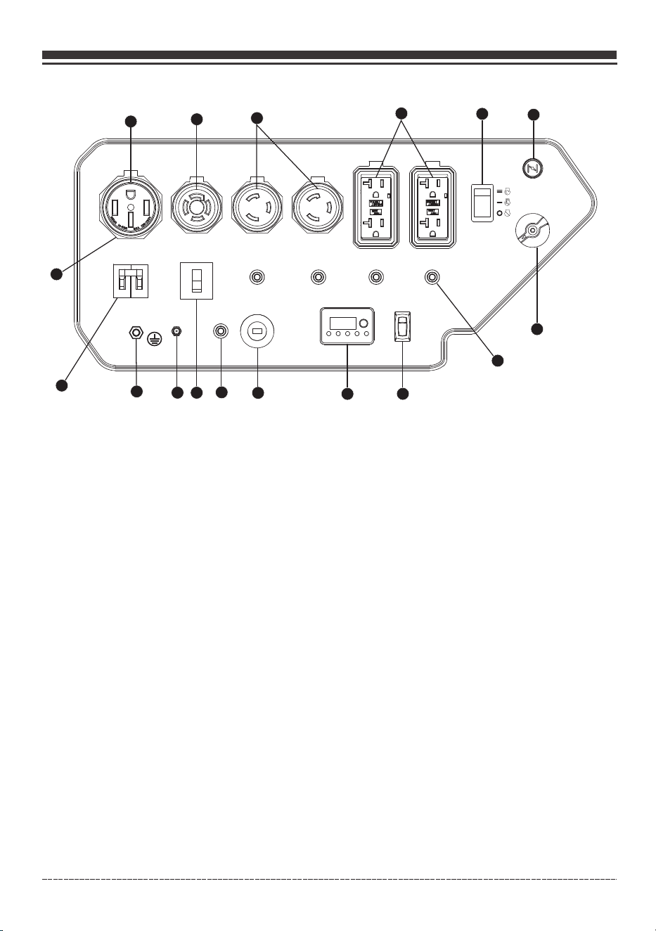
1. 120/240V, 50A – (NEMA 14-50R) (Not GFCI protected)
Maximum full load current may be drawn from this 120/240 Volt, 50 Amp receptacle.
2. 120/240V, 30A Twist Lock – (NEMA L14-30R) (Not GFCI protected)
6. Choke Knob
7. Fuel Valve Knob
The Economy Control switch can be activated in order to minimize fuel consumption and noise while
operating the unit during times of no electrical output, allowing the engine speed to idle during periods of
no electrical usage. The engine speed returns to normal when an electrical load is connected. When the
economy switch is off, the engine runs at normal speed continuously.
8. Economy Control Switch
15
Control Panel
NOTICE Total power drawn from all receptacles must not exceed the name plate rating.
A maximum of 30 Amps current for 240 Volts or two independent 120 Volt loads at 30 Amps current each.
3. 120V, 30A Twist Lock – NEMA L5-30R(Not GFCI protected)
A maximum of 30 Amps current may be drawn from this receptacle.
4. 120V, 20A Duplex GFCI (Ground Fault Circuit Interrupter)- NEMA 5-20R
A maximum of 20 Amps current may be drawn from this duplex receptacle.
5. Engine Start Switch – To start engine, press and hold the switch in the START (ll) position, the
engine will crank and attempt to start. When the engine starts, release the switch to the RUN (l) position.
10. 12V DC Outlet – 8.3 Amp of DC current may be drawn from this receptacle.
Use this outlet to charge 12V automotive type batteries ONLY. See 12V DC outlet (Battery Charger) section.
11. DC Circuit Breaker - The circuit protector may be reset by pushing the button of the protector.
12. 12V DC Battery Charger Port - Plug the 120 Volt AC charger into this port to charge the generator
battery.
9. 4-1 Data-Minder (Multi-Meter) – Push the SELECT button to show the Voltage, Hertz, running hours and
low oil alarm.
13. Ground Terminal – Consult an electrician or authority having jurisdiction for local grounding
requirements.
English Customer Service: 1-844-FIRMAN1
10
14. Circuit Breakers – The receptacles are protected by AC circuit protectors. If the generator is
overloaded or an external short circuit occurs, a circuit protector may trip. If tripping occurs,
disconnect all electrical loads and determine the cause before attempting to continue using the
generator. Reset any tripped circuit protectors.
If multiple receptacles are used at the same time, the total current must be kept with-in the
portable generator data decal rating.
15. Outlet Cover - Protect the receptacles from dust and debris.
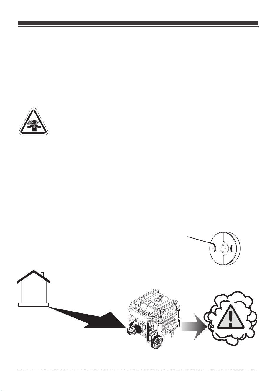
1.Location
DANGER! Engine exhaust contains carbon monoxide, a poisonous gas that could kill
you in minutes. You CANNOT smell it, see it, or taste it. Even if you do not smell exhaust
fumes, you could still be exposed to carbon monoxide gas.
•
•
•
Operate portable generator only outdoors, at least 20 ft. from occupied spaces with exhaust pointed
away to reduce the risk of carbon monoxide accumulating.
Install battery-operated carbon monoxide alarms or plug-in carbon monoxide alarms with
battery back-up according to the manufacturer's instructions. Smoke alarms cannot detect
carbon monoxide gas.
Do not run this portable generator inside homes, garages, basements, crawlspaces, sheds, or
other partially-enclosed spaces even if using fans or opening doors and windows for ventilation.
Carbon monoxide can quickly build up in these spaces and can linger for hours, even after this
product has shut off.
•
If you start to feel sick, dizzy, weak or your home’s carbon monoxide alarm sounds, get to fresh air
right away. Call emergency services. You may have carbon monoxide poisoning.
Carbon Monoxide Alarm(s)
Install carbon monoxide alarms inside your home. Without working
carbon monoxide alarms, you will not realize you are getting sick and
dying from carbon monoxide poisoning.
Prevent Carbon Monoxide (CO) Poisoning
Use outdoors at least 20 ft. (6.0 m) from any home.
Point exhaust away from all homes and occupied spaces.
Install CO alarms inside your home.
20 ft. (6.0 m) min.
To better educate yourself about all carbon monoxide risks,
go to www.takeyourgeneratoroutside.com.
OPERATION

English Customer Service: 1-844-FIRMAN1
Reduce Risk of Fire
WARNING! Exhaust heat/gases could ignite combustibles, structures or damage fuel
tank causing a fire, resulting in death or serious injury.
Keep portable generator at least 5 ft. (1.5m) from any structure, trees or vegetation over 12
in. (30 cm) in height.
•
Select an outdoor site that is dry and protected from the weather. Do not move portable
generator indoors to protect it from the weather.
Do not locate the portable generator under a deck or other similar structure that may
confine heat and airflow.
•
•
11
OPERATION
5 ft.(1.5m)
min.
5 ft.(1.5m)
min.
20 ft.(6m)min.
I
~"'•
..
'
~
•'t
I '
'
\ .
,
'
,,,
...
English Customer Service: 1-844-FIRMAN1
2. Oil and Gasoline
Add Engine Oil
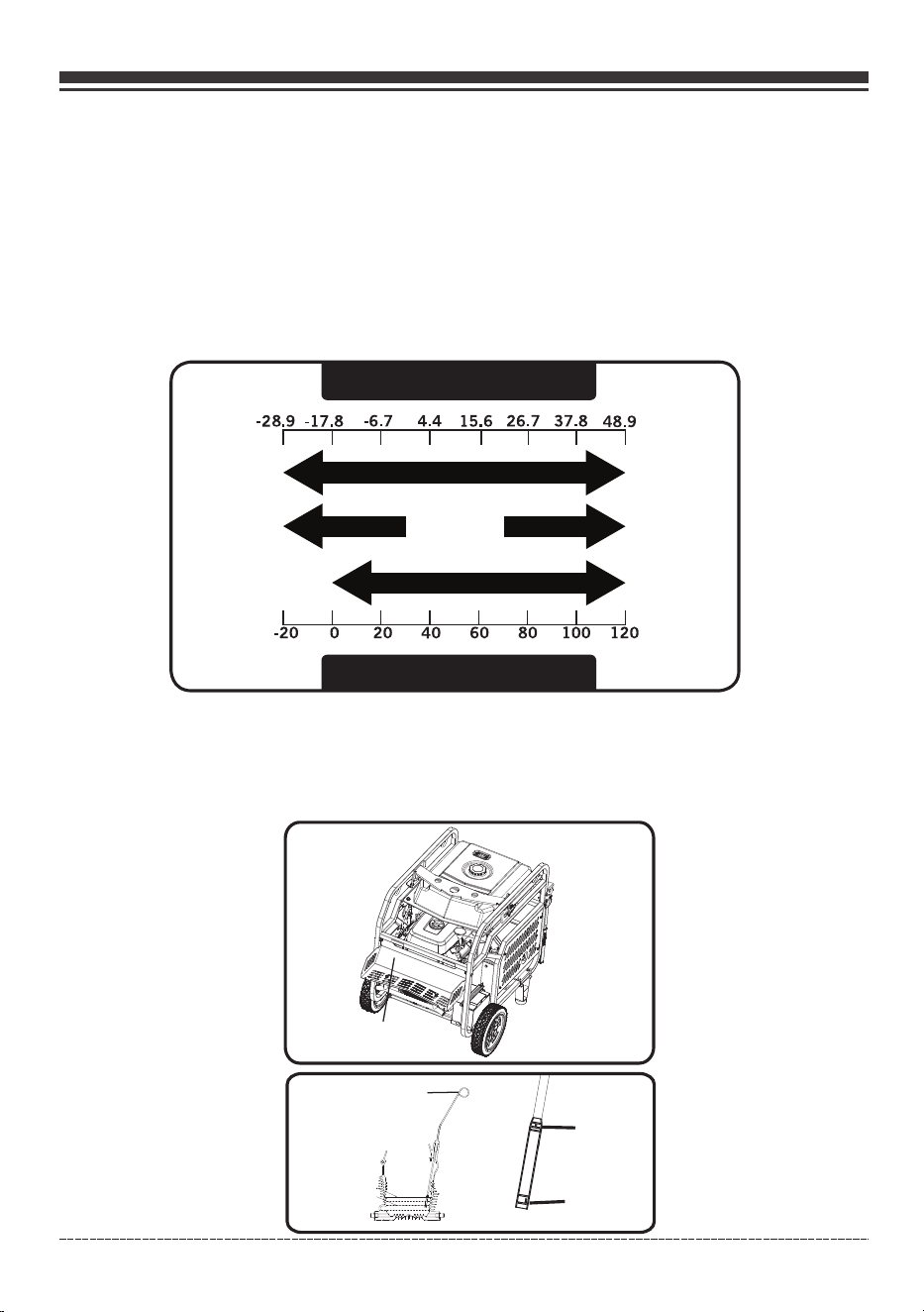
We recommend using FIRMAN SAE 10W-30 API SL oil for best performance. Other high-quality
detergent oils (API SL or higher) are acceptable. Do not use special additives. Ambient temperature
determines the proper oil viscosity for the engine. Use the chart to select the proper oil for the
outdoor temperature range expected.
NOTICE Do not attempt to crank or start the engine before it has been properly filled with the
recommended type and amount of oil. Damage due to operation with no oil will void your warranty.
Degrees Celsiusº(Outside)
Full Synthetic 5W-30
Degrees Fahrenheitº(Outside)
5W-30 10W-40
10W-30
1.Place generator on a flat, level surface.
3.Clean area around oil fill and remove yellow oil fill cap/dipstick.
4.Wipe dipstick clean.
12
OPERATION
2.Open the maintenance cover.
Maintenance Cover
H
L
Dipstick
-28.9 -17.8
-6.7
4.4
15.6
26.7
37.8
48.9
- -
-
-
- -
-20 0
20
40
60
80
100 120
[
English Customer Service: 1-844-FIRMAN1
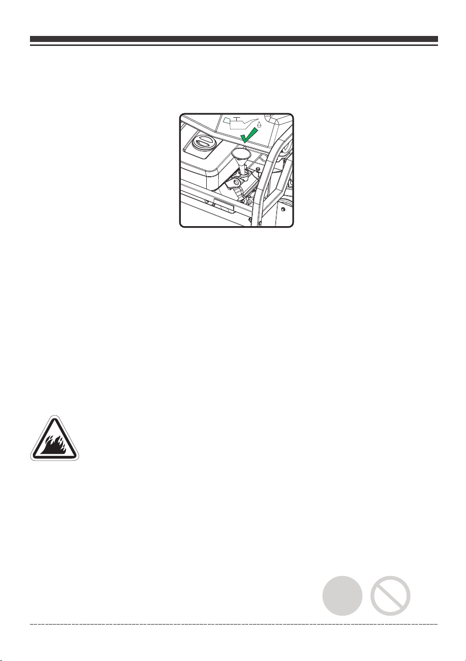
5. Using oil funnel, slowly pour contents of provided oil bottle into oil fill opening until oil reaches
upper limit "H" mark on the dipstick. Be careful not to overfill. Overfilling could cause engine
starting problems or engine damage.
6.Replace oil fill cap/dipstick and fully tighten.
7.Oil level should be checked prior to each use or at least every 8 hours of operation. Keep oil
level maintained.
8. Close maintenance cover.
The portable generator is equipped with a low oil shutdown. If the oil level drops below the
minimum required level, a sensor will activate an internal switch stopping the engine. If the
engine shuts off and the oil level is within specifications, check to see if generator is sitting at an
angle. Place portable generator on an even surface to correct this. If engine fails to start, the oil
level may not be high enough to deactivate the internal low oil level switch. Make sure the sump is
completely full of oil to the upper limit (H). Do not operate engine until oil level issue is corrected.
Contact Firman customer service.
Low Oil Shutdown
Add Gasoline
WARNING! Fuel and its vapors are extremely flammable which could cause burns or fire
resulting in death or serious injury.
Turn generator engine OFF and let it cool at least 2 minutes before removing fuel cap.
Do Not refuel or move generator when engine is running.
Move generator outdoors prior to adding or draining fuel
Keep fuel away from any ignition sources.
Do not overfill tank, allow space for fuel expansion.
If any fuel spills, wait until it evaporates before starting engine
Check and replace fuel lines, tank, cap, and fittings prior to each use if any damage or leaks
are found.
•
•
•
•
•
•
•
Fuel must meet these requirements:
Clean, fresh, unleaded gasoline with a minimum of 87 octane.
For high altitude use, see Operation at High Altitude.
Gasoline with no more than 10% alcohol is acceptable.
•
•
•
E10
E15
13
OPERATION
English Customer Service: 1-844-FIRMAN1
NOTICE Do not mix oil in gasoline or modify engine to run on alternate fuels not described in this
manual. Use of unapproved fuels could damage engine and will not be covered under warranty.
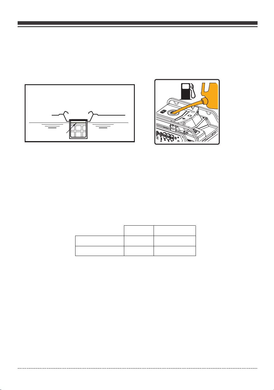
1. Clean area around fuel fill cap, remove cap.
2. Slowly add unleaded fuel to fuel tank. Be careful not to fill above the RED fuel level indicator.
This allows adequate space for fuel expansion.
Red Line Indicator
3. Install fuel cap and let any spilled fuel evaporate before starting engine.
Operation at High Altitude Gasoline Only
At altitudes over 5,000 feet(1524 meters), a minimum 85 octane gasoline is acceptable.
Engine power and generator output will be reduced approximately 3.5% for every 1000 feet (305 m)
of elevation above sea level. High altitude may cause hard starting, increased fuel consumption
and sparkplug fouling. To operate at high altitudes FIRMAN can provide a high altitude carburetor
main jet. The alternative main jet and installation instructions can be obtained by contacting
Customer Support. Installation instructions are also available in the Technical Bulletin area of the
FIRMAN website www.firmanpowerequipment.com.
NOTICE Operation using an alternative main jet at elevations lower than the recommended
minimum altitude can damage the engine. For operation at lower elevations, the standard main
jet supplied must be used. Operating the engine with the wrong main jet may increase exhaust
emissions, fuel consumption and reduce performance.
Altitude main jet 1
Altitude main jet 2
760cc
399715868
399715869
Altitude
3000-6000Feet
6000-8000Feet
Operation at High Ambient conditions
Your Firman Power Equipment product is designed and rated for continuous operation at ambient
temperatures up to 40°C (104°F). The generator may be operated at temperatures ranging from
-15°C (5°F) to 50°C (122°F) for short periods. If the generator is exposed to temperatures outside
this range during storage, the generator should be brought back within this range before
operation. When operated above 77°F(25°C) there may be a decrease in pow er.
Maximum wattage and current are subject to and limited by such factors as fuel BTU content
ambient temperature, altitude, engine conditions etc.
14
OPERATION
I I
English Customer Service: 1-844-FIRMAN1
3.Starting the Generator on Gasoline
1. Before starting the generator, check for loose or missing parts and for any damage which may
have occurred during shipment. Ensure spark plugs, muffler, fuel cap, and air cleaner are all in place.
2. Move portable generator outdoors to safe operating location at least 20
feet from any occupied spaces.
15
OPERATION
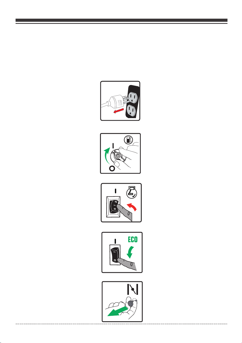
3. Disconnect all electrical loads from the generator. Never start or stop the generator with
electrical devices plugged in.
5. Flip the engine switch to the “RUN(l)” position.
4. Turn the fuel valve to the “ON” (l)position.
6. Flip the ECO switch to the “OFF(O)” position.
6. Move choke knob located on panel to “START” position. You do not need to choke a warm engine.
I
ECO
~
English Customer Service: 1-844-FIRMAN1
16
OPERATION
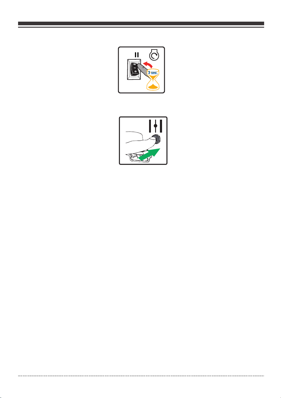
8. Flip the engine switch to the START (ll) position for a few seconds and then release.
9. Do not over-choke. As soon as engine starts and warms up, slowly move the choke knob to the
RUN position.
10. Allow portable generator to run at no load for a few minutes to stabilize before plugging in
any electrical devices.
NOTICE If engine starts but fails to run, or if portable generator shuts down during operation,
check oil level. See Low Oil Shutdown section for more information.
English Customer Service: 1-844-FIRMAN1
This portable generator has been pretested and adjusted to handle its full capacity. The voltage is
regulated using an automatic voltage regulator (AVR) . Readjusting the AVR will void warranty.
4. Connecting Electrical Loads
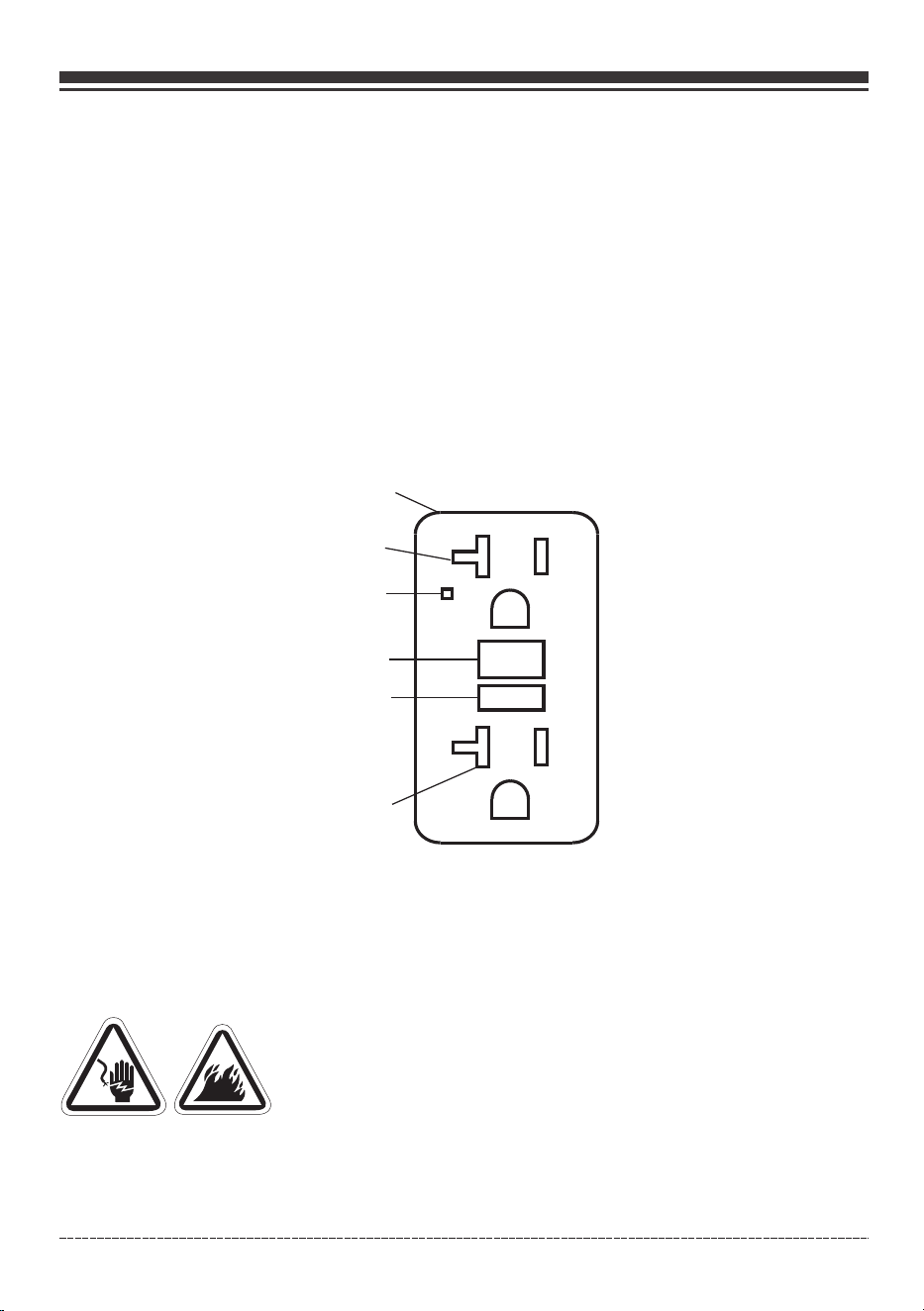
The duplex receptacle is equipped with GFCI protection. The GFCI protects against electric shock
that may be caused if you become a path which electricity travels to reach earth. Even with a GFCI
you may feel a shock, but the GFCI cuts power quickly so an average person should not suffer any
injury. Manual test GFCI while generator is running to verify internal contacts will function
Push the test button. The reset button will pop out, which should cut power to outlet.
Press the reset button until it locks in the depressed position. If the GFCI does not reset as
described do not use the receptacles. Call Firman customer service.
If GFCI trips while in use, reset and test the outlet. Electric cords laying on the ground with
worn insulation may trip the GFCI, only use cords in good condition.
•
•
•
RESET
TEST
TEST MONTHLY
FOLLOW DIRECTIONS
RESET BUTTON
Receptacle
Outlet
LED Indicator Light
TEST BUTTON
Outlet
In addition to the manual test / reset feature the GFCI receptacle tests itself periodically to
confirm the GFCI electronics are functional. The indicator light will be solid green when the
GFCI is powered from the generator and working correctly.
Self-test indications: If the indicator light is solid orange or flashing red a problem may exist.
Press the TEST button to trip the GFCI. If unable to reset, replace the GFCI.
SELF-TEST OPERATION
Damaged or overloaded extension cords could overheat, arc, and burn resulting death or
serious injury.
Use a ground fault circuit interrupter (GFCI) in any damp or highly conductive area, such as
metal decking.
Do not touch bare wires or receptacles.
WARNING! Generator voltage could cause electrical shock or burn
resulting in death or serious injury.
•
•
•
17
OPERATION
c::{]
D
-----+-------LI
0
D
0
English Customer Service: 1-844-FIRMAN1
Do not use generator with electrical cords which are worn, frayed, bare or otherwise damaged.
Do not operate generator in the rain or wet weather.
Do not run indoors to avoid wet conditions.
Do not handle generator or electrical cords while standing in water, while barefoot, or while
hands or feet are wet.
Use listed transfer switch to prevent backfeed by isolating generator from electric utility
workers.
•
•
•
•
•
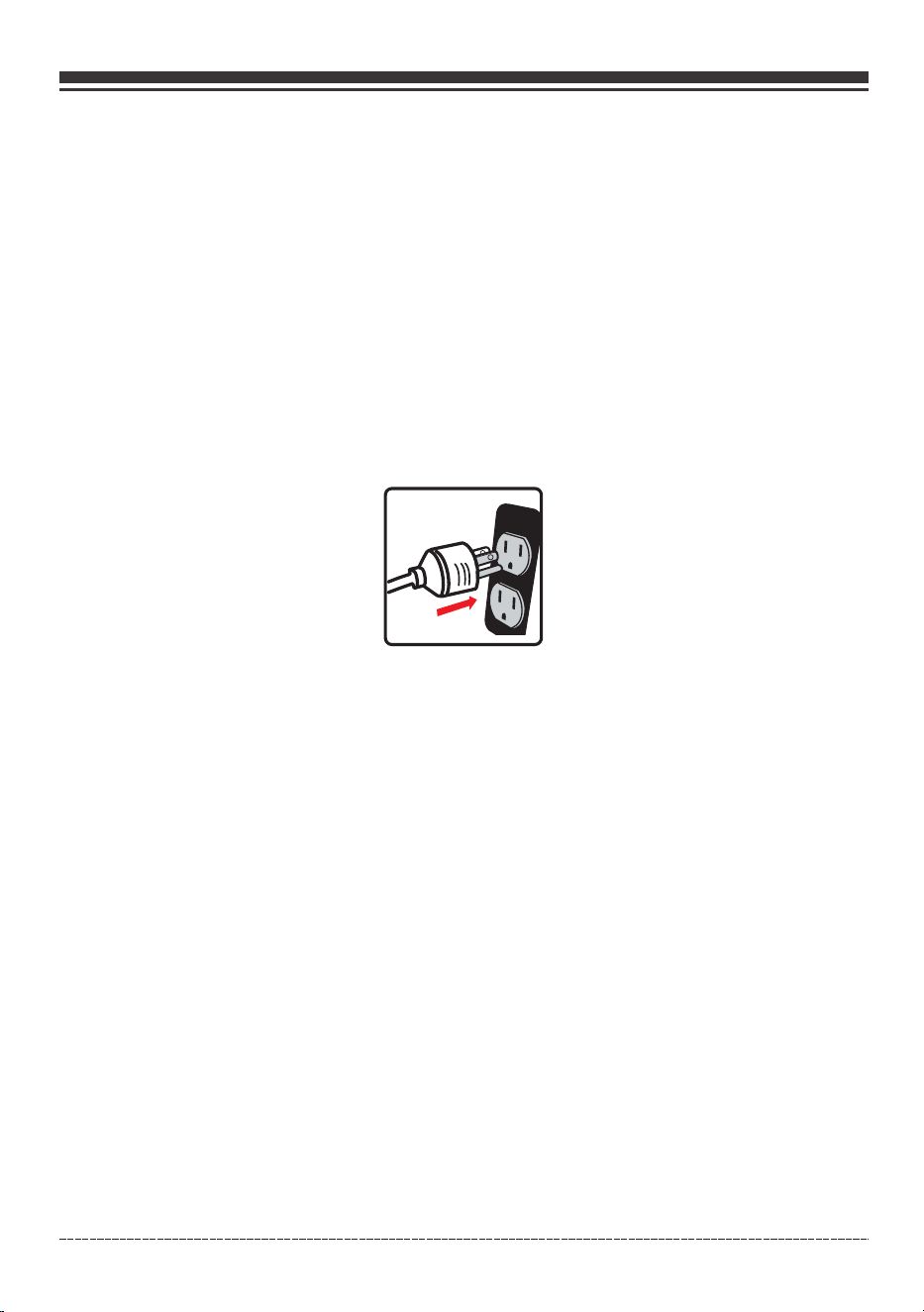
1.Ensure circuit breaker on control panel is in the closed (on) position.
2. Start the generator with no electrical load attached.
3. Allow the engine to run for several minutes to stabilize.
4. Plug in and turn on the first item. It is best to attach the item with the largest load first.
5. Allow the engine to stabilize.
6. Plug in and turn on the next item.
7. Allow the engine to stabilize.
8. Repeat steps 5-6 for each additional item.
Surge Protection
There is a remote chance that voltage fluctuations may impair the proper functioning of some
sensitive electronic equipment. Electronic devices, including computers and many programmable
appliances may use components that are designed to operate within a narrow voltage range and
may be affected by the portable generator’s momentary voltage fluctuations. While there is no
way to prevent all voltage fluctuations, you can take steps to protect your sensitive electronic
equipment. Install a plug-in surge suppressor on the receptacles feeding your sensitive equipment.
Surge suppressors come in single or multi-outlet styles. They are designed to protect against short
duration voltage fluctuations.
18
OPERATION
English Customer Service: 1-844-FIRMAN1
19
OPERATION
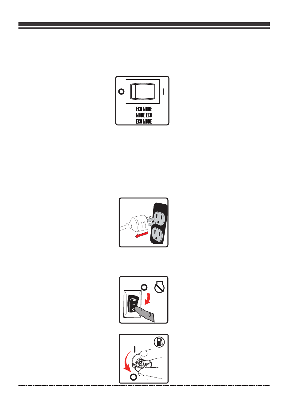
2. Flip the engine switch to“OFF”(O) position.
3. Turn the fuel valve to the “OFF”(O) position.
5. Stopping the generator
1. Turn off and remove all electrical loads.
Never stop the generator with electrical devices plugged in and turned on.
Never stop the engine by moving the choke to the start position.
Let the generator run at no-load for one minute to stabilize internal temperatures of the engine
and generator.
Economy Control Switch
The Economy Control switch can be activated in order to minimize fuel consumption and noise
while operating the unit during times of reduced electrical output, allowing the engine speed to
idle during periods of non-use. The engine speed returns to normal when an electrical load is
connected. When the economy switch is off, the engine runs at normal speed continuously.
NOTICE:
For periods of high electrical load or momentary fluctuations, the Economy Control Switch should
be turned OFF. For electrical appliances that can’t started below 180V, the Economy Control Switch
should be turned OFF.
o[g1
ECO
MODE
MODE
ECO
ECO
MODE

English Customer Service: 1-844-FIRMAN1
Maintenance - Storage
General Recommendations
Regular maintenance will improve the performance and extend the life of the generator. See any
authorized dealer for service.
The generator's warranty does not cover items that have been subjected to operator abuse or
negligence. To receive full value from the warranty, the operator must maintain the generator as
instructed in this manual.
Some adjustments will need to be made periodically to properly maintain your generator.
All service and adjustments should be made at least once each season. Follow the requirements
in the maintenanc shedule chart above.
NOTICE Once a year you should clean or replace the spark plugs and replace the air filter. New
spark plugs and clean air filter assure proper fuel-air mixture and help your engine run at peak
performance and last longer.
To be performed by knowledgable/experienced owner or by authorized service center.
*
MAINTENANCE SCHEDULE
ITEM NOTES
Daily(Before
operation)
Initial
25 hours
Every
50 hours
Every
100 hours
(or annual)
Fittings/
Fasteners
Spark Plug
Engine Oil
Air Filter
Fuel Line
Exhaust
System
Engine
Check condition. Adjust gap
and clean. Replace if necessary.
Check oil level.
Clean, replace if necessary.
Check for leakage. Retighten or
replace gasket if necessary.
Check adjust valve clearance.
Clean combustion chamber.
Check. Replace if necessary.
Check fuel hose for cracks or other
damage. Replace if necessary.
√
√
√
√
√
√
√
√
√
√
Replace.
Check spark arrester screen.
Clean/Replace if necessary.
Every
250 hours
√
*
*
Fuel
Clean fuel tank strainer.
Replace if necessary.
√
20
Oil Filter
Replace.
√ √
Fuel Filter
Replace.
√
English Customer Service: 1-844-FIRMAN1
When Transporting Generator
Transport with fuel tank EMPTY or with fuel valve knob in OFF position.
Do not tip generator at an angle which causes fuel to spill.
Disconnect LPG/ NG fuel hose and securely stow away.
ENGINE MAINTENANCE
To prevent accidental starting, remove and ground spark plug wires before performing any service.
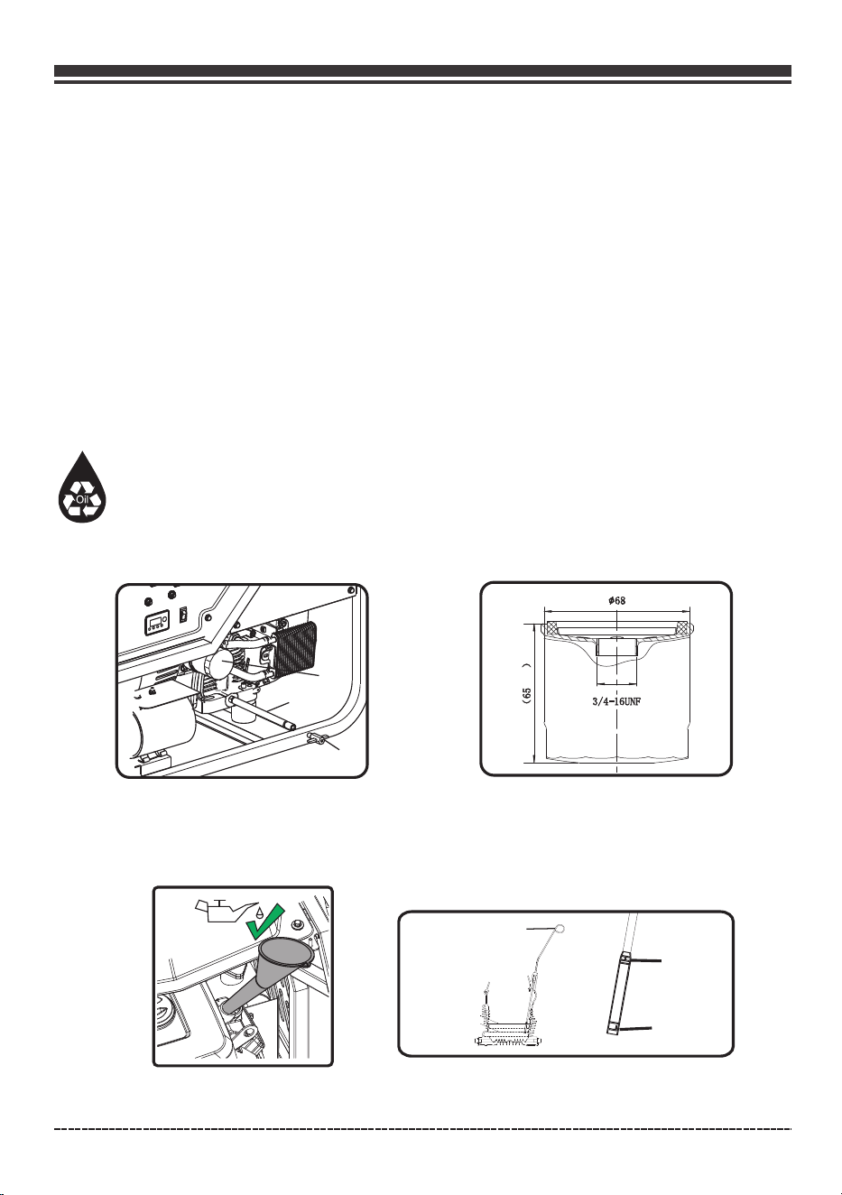
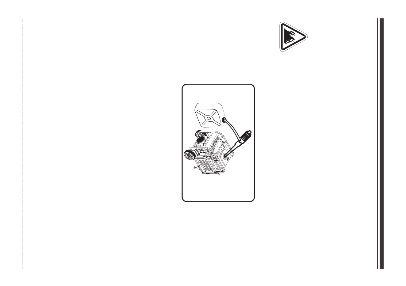
Change Engine Oil and Oil filter
Change engine oil every 100 hours. (for a new engine, change oil and oil filter after 25 hours.)
If you are using your generator under extremely dirty or dusty conditions, or in extremely hot
weather change the oil more often.
CAUTION! Avoid prolonged or repeated skin contact with used motor oil. Used motor oil has been
shown to cause skin cancer in certain laboratory animals. Thoroughly wash exposed areas with
soap and water.
KEEP OUT OF REACH OF CHILDREN. DON’T POLLUTE. CONSERVE RESOURCES. RETURN USED OIL
TO COLLECTION CENTERS.
(b) Change the Oil filter. Turn close the drain oil plug and fill the engine with oil until it reaches
the HIGH(H) level on the oil filler dipstick.
NOTICE We recommend using FIRMAN SAE 10W-30 API SL oil for best performance. Other high-
quality detergent oils (API SL or higher) are acceptable. See Oil and Gasoline
21
Maintenance - Storage
(a) Turn on the drain oil plug A and drain oil by the drain hose B. Removing oil filler cap while the
engine is warm.
H
L
Dipstick
A
B
C
mm
mm
Oil Filter: FIRMAN P/N
BOSCH 0986AF0062 or FRAM PH4967F.
399715751,
[
English Customer Service: 1-844-FIRMAN1
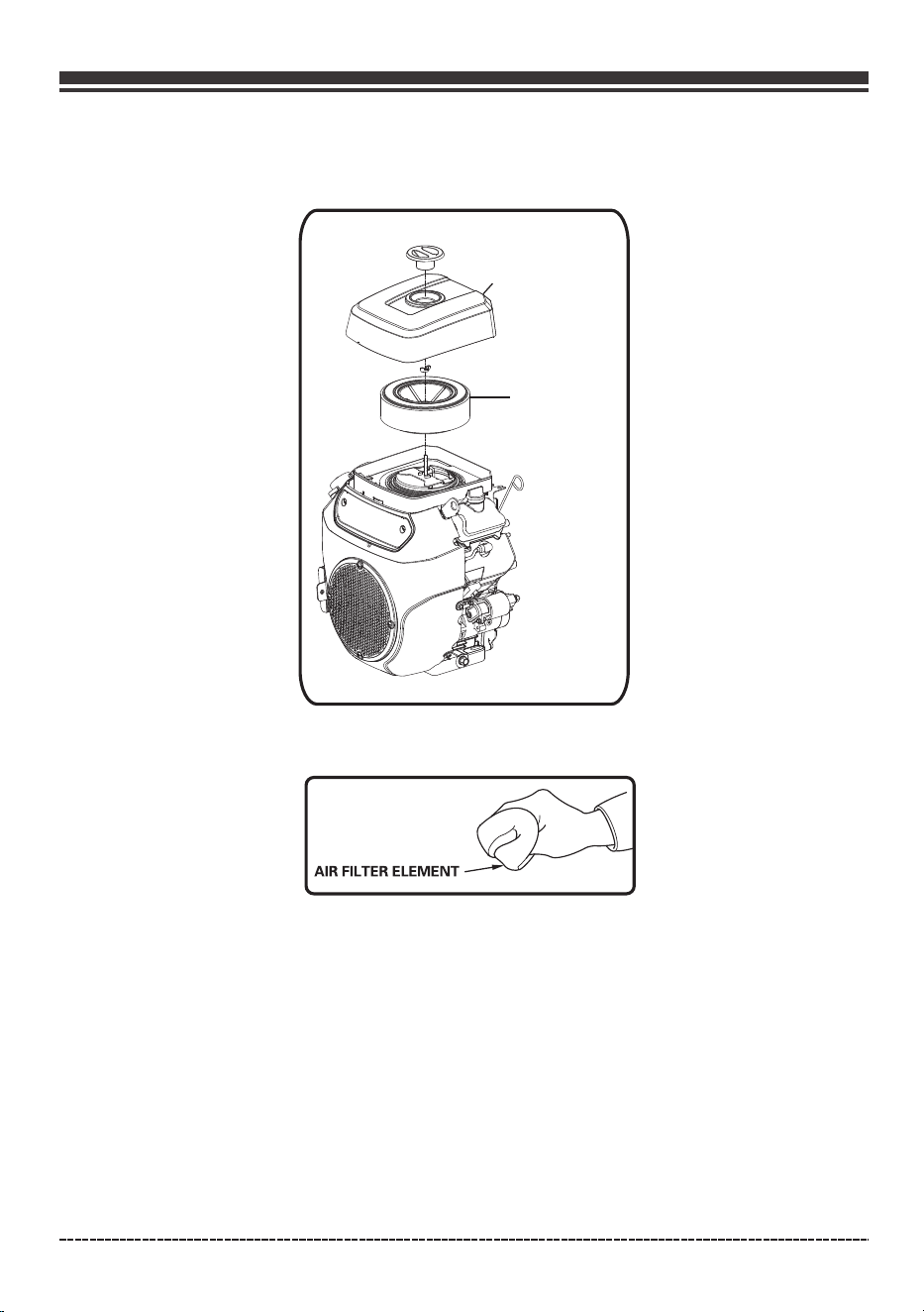
Air Filter Maintenance
(a) Carefully remove foam air filter element and wash it with liquid detergent and water only.
Squeeze dry in a clean cloth.
(b) Saturate foam air filter element with clean engine oil and squeeze in a clean cloth to remove
excess oil.
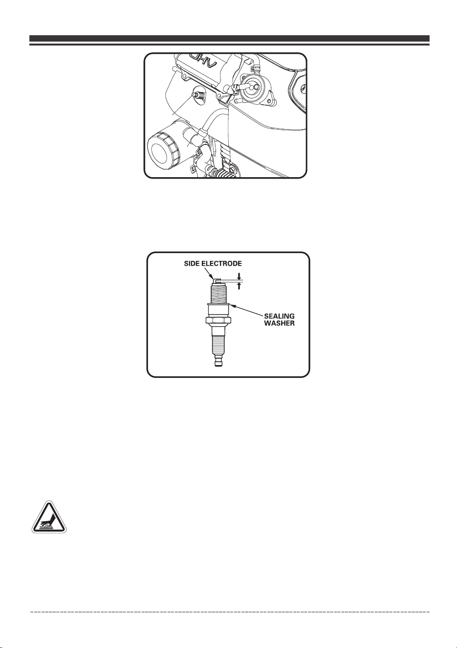
Spark Plug Maintenance
Changing the spark plugs will help your engine start easier and run at peak performance.
(a) Remove the spark plug boots.
(b) Remove spark plugs using provided wrench.
22
( ) Reinstall clean or new air filter element.c
Maintenance - Storage
AIR CLEANER
COVER
AIR FILTER
ELEMENT
AIR
FILTER
ELEMENT
English Customer Service: 1-844-FIRMAN1
( c) Inspect spark plug for damage and clean with a wire brush before reinstalling. Replace if
damaged.
(d) Adjust the electrode gap to 0.028” to 0.031” (0.7 to 0.8 mm).
(e) Seat spark plug in position and thread by hand to prevent cross threading.
(f) Tighten plug with provided wrench and put the spark plug boot back on spark plug.
SPARK PLUG: FIRMAN P/N 330723001 or CHAMPION N9YC
Maintenance Valve Clearance
Intake: ( )
Exhaust: 0.004 – 0.006 in. (0.10 – 0.15 mm)
0.004 – 0.006 in. 0.10 – 0.15 mm
Muffler and Spark Arrester
•
•
WARNING! Contact with muffler area could cause burns resulting in serious injury.
Do not tough hot parts.
It is a violation of California Public Resource Code, Section 4442, to use or operate the engine
on any forest-covered, brush-covered, or grass-covered land unless the exhaust system is
equipped with a spark arrester, as defined in Section 4442, maintained in effective working
order. Other states or federal jurisdictions may have similar laws, reference Federal
Regulation 36 CFR Part 261.52.
23
Maintenance - Storage
A
B
A- Spark plug
B- Spark plug boot
0.028-0.031 in
(0.7-0.8 mm)
SIDE ELECTRODE
SEALING
WASHER
English Customer Service: 1-844-FIRMAN1
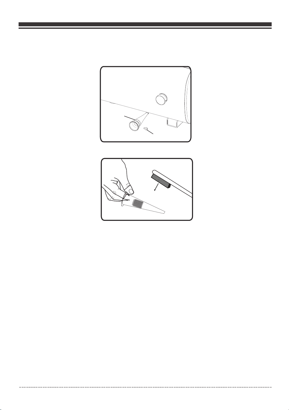
Inspect Muffler and Spark Arrester
1.Inspect the muffler for cracks, corrosion, or other damage.
2.Remove the screws securing the spark arrester in place and the remove it from muffler.
3. Carefully remove the carbon deposits from the spark arrester screen with a wire brush.
4. Replace the spark arrester if it is damaged. If replacement parts are required, make sure to use
only FIRMAN original equipment replacement parts.
5. Position the spark arrester in the muffler and attach with the screws.
NOTICE Failure to clean or replace spark arrester may result in decreased engine performance.
GENERATOR MAINTENANCE
Make certain that the portable generator is kept clean and dry.
Do not expose the unit to excessive dust, dirt, moisture or corrosive vapors.
Do not insert any objects through cooling slots.
Before each use inspect underneath the generator for signs of oil or fuel. Clean any accumulated
debris. Keep area around muffler free from any debris. Use a soft bristle brush to remove dirt or
caked on oil. Use a damp cloth to clean all exterior surfaces.
24
Run the generator at least 30 minutes every month.
Maintenance - Storage
Spark arrester
screen
Screw
English Customer Service: 1-844-FIRMAN1
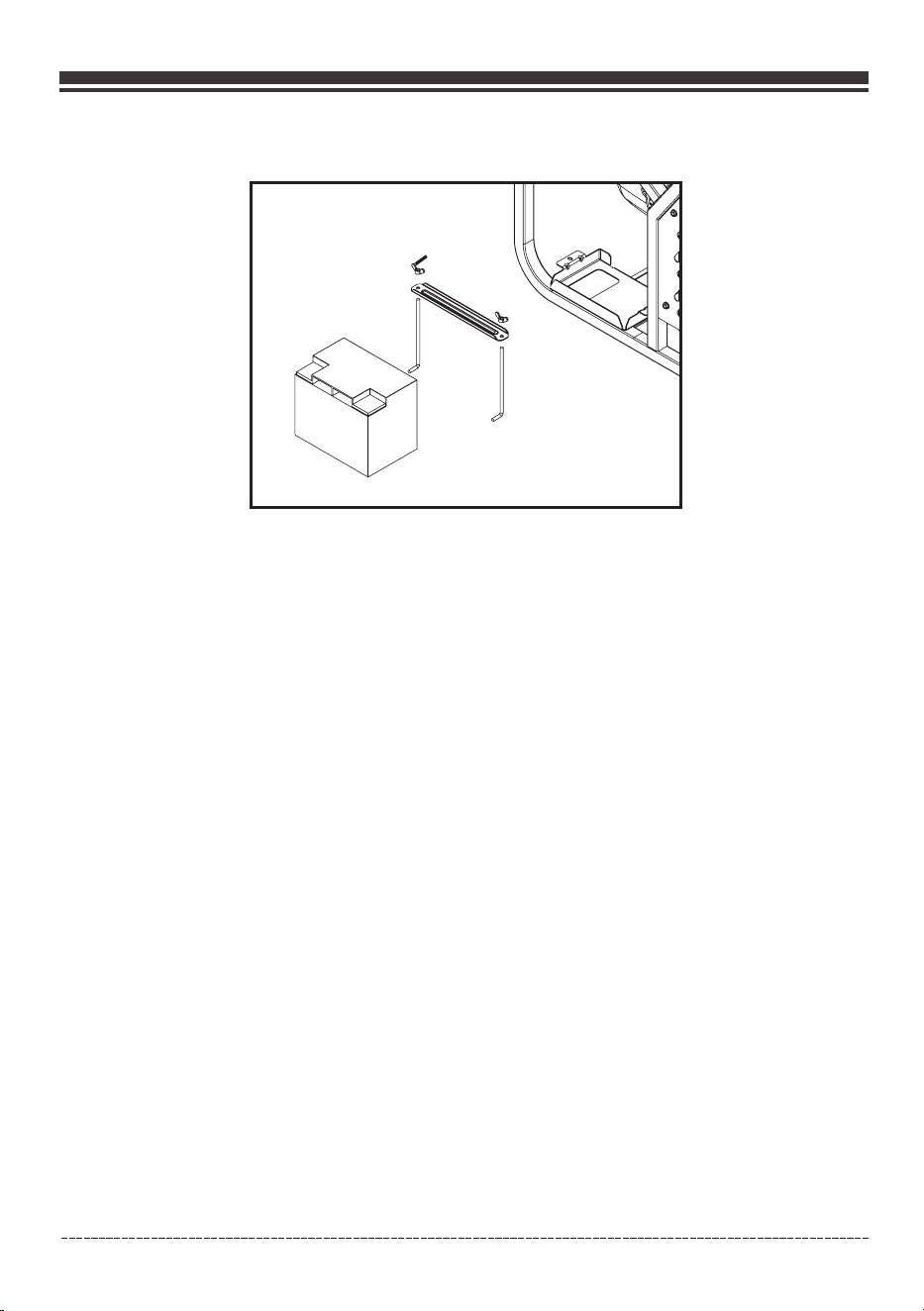
Battery Replacement
A(M6)
1. Remove the spark plug boot from spark plugs.
2. Remove the nut and bolt from the negative(-) post first, then the positive(+) post.
3. Loosen and remove the wing nuts (A) on the battery holding bracket.
4. Remove the battery and recycle.
5. Install the new battery with the following specification:
12V sealed lead acid 33AH
LXWXH:7.67X5.12X6.3inch (195X130X160mm)
6. Connect the red positive (+) battery cable to the battery first.
7. Connect the black negative (-) battery cable to the battery second.
8. Cover the posts with boots provided.
9. Install the spark plug boot onto spark plugs.
The battery powers the starter motor and control module. This portable generator is equipped
with an automatic battery charging circuit. The battery will receive charging voltage only when
the engine is running. The battery will maintain a proper charge if the portable generator is used
on a regular basis (about once every two weeks). If it is used less frequently, the battery should
be connected to the trickle charger provided to keep the battery properly charged. If the battery
is not able to start the engine, the battery must be connected to a standard automotive style
battery charger for re-charging before it can be used.
Battery Charging
25
Maintenance - Storage
English Customer Service: 1-844-FIRMAN1
It is important to prevent gum deposits from forming in essential fuel system components such
as the carburetor, fuel hoses or tank during storage. Alcohol-blended fuels (called gasohol, ethanol
or methanol) attract moisture, which leads to separation and formation of acids during storage.
Acidic gas can damage the fuel system of an engine while in storage.
Long Term Storage
When the generator set is being stored for more than one month, follow these instructions to avoid
engine problems:
Do not store fuel near any ignition sources.
When draining fuel move generator outdoors and use a commercially available non-conductive
vacuum siphon. Fuel must be drained into an approved container.
WARNING! Fuel and its vapors are extremely flammable which could cause burns
or fire resulting in death or serious injury.
1-Treat any stored fuel with fuel stabilizer.
2-When storing generator with gasoline in fuel tank, operate the engine for 5-10 minutes to
circulate treated fuel into fuel lines and carburetor before shutdown.
3- There is no need to drain gasoline from the generator fuel tank if fuel stabilizer is added.
4-FUEL STARVATION: If you elect to drain fuel tank move generator outdoors. Once fuel tank is
drained turn fuel valve knob to on position. Start and run the portable generator outdoors until
engine stops from lack of gasoline. This will drain remaining gasoline from tank, fuel lines, and
carburetor.
5-Always turn fuel valve knob to OFF position prior to storage.
6-Allow the portable generator to cool before cleaning and storage.
7-Change oil .
8-Remove spark plug boots and spark plugs. Pour about one teaspoon of engine oil through the
spark plug holes, cover each spark plug hole with a clean rag then quickly jog the engine three
times with the engine switch to distribute the oil in the cylinders. Reinstall the spark plugs and
attach the spark plug boots.
9-Cover the portable generator and store in a clean, dry place out of direct sunlight and away from
any ignition sources.
Any damage or hazards caused by using improper fuel, improperly stored fuel, and/or improperly
formulated stabilizers, are not covered by manufacturer's warranty.
Do not store gasoline from one season to another season.
26
Maintenance - Storage
~
o'
-'

Troubleshooting – Specifications
English Customer Service: 1-844-FIRMAN1
Problem Cause Correction
Engine is running, but no
AC output is available.
1. Circuit breaker is open.
2. Fault in generator.
3. Poor connection or defective cord set.
4. Connected device is bad.
1. Reset circuit breaker.
2. Contact authorized service facility.
3. Check and repair.
4. Connect another device that is in
good condition.
Engine runs good at
no-load but “bogs down”
when loads are connected.
1. Short circuit in a connected load.
2. Engine speed is too slow.
3. Shorted generator circuit.
1. Disconnect shorted electrical load.
2. Contact authorized service facility.
3. Contact authorized service facility.
Engine will not start; starts
and runs rough or shuts
down when running.
1. Fuel switch set to OFF (O)
position.
3. Low oil level.
4. Dirty air cleaner.
5. Out of gasoline.
6. Stale gasoline.
7. Spark plug wires not connected
to spark plugs.
8. Bad spark plugs.
9. Water in gasoline.
10. Flooded.
11. Excessively rich fuel mixture.
1. Set fuel switch to “ON” position.
3. Fill crankcase to proper level or
place generator on level surface.
4. Clean or replace air cleaner.
5. Fill fuel tank with gasoline.
6. Drain fuel tank and carburetor; fill
with fresh gasoline.
7. Connect wires to spark plugs.
8. Replace spark plugs.
9. Drain gas tank and carburetor; fill
with fresh gasoline.
10. Wait 5 minutes and re-crank engine.
11. Contact authorized service facility.
Engine lacks power.
1. Load is too high.
2. Dirty air filter.
1. Don't Overload Generator
2. Replace air filter.
Engine“hunts”or falters.
1. Carburetor is running too rich or too lean.
1. Contact authorized service facility.
12. Clogged or dirty fuel filter.
4. Clean or replace fuel filter.
12. Clean or replace fuel filter.
3. Clogged or dirty fuel filter.
4. Clogged spark arrester.
3. Clean or replace fuel filter.
4. Clean or replace spark arrester.
2. Clogged or dirty fuel filter.
2. Clean or replace fuel filter.
Engine shuts down when
running.
1. Out of gasoline.
2. Dirty air cleaner.
3. Low oil level.
1. Fill fuel tank with gasoline.
2. Clean or replace air cleaner.
3. Fill crankcase to proper level or place.
generator on level surface.
4. Clogged or dirty fuel filter.
13. Starting battery may have
insufficient charge.
13. Check battery output and charge
battery as necessary.
2. The indicator light is OFF or
flashing red.
2. Must have solid red indicator light
to be able to start the engine.
14. Out of battery power.
14. Start Engine to charge or
replace battery.
For all other issues, contact authorized dealer or Firman customer service.
27

SPECIFICATIONS
Model
Rated AC Voltage
Phase
Power Factor
Voltage Regulator
Alternator Type
Running Watts*
Starting Watts
Engine
Engine Type
Displacement
Low Oil Shutdown
Ignition System
Starting System
Fuel
Capacity Fuel Tank
Lubricating Oil Capacity
Carburetor Type
Air Cleaner
P.T.O. Shaft Rotation
120/240V
P12001
12000
AVR
Single
1
V-twin, 4-Stroke OHV Air Cooled
760cc
Breakless Ignition Type, Flywheel Magneto
Unleaded Automotive Gasoline
13.3 U.S. Gallons (50.2L)
50.7 oz (1.5L)
Counter Clockwise (Facing P.T.O.)
Float
Brushed
Polyurethane Type
Yes
15000
FIRMAN
Rated Fequency
60Hz
Oil Type
See “Add Engine Oil” Section
Electric Start
English Customer Service: 1-844-FIRMAN1
AC Grounding System
Neutral Bonded To Frame
28
Troubleshooting – Specifications
*Generator certified in accordance with CSA (Canadian Standards Association) standard C22.2 No. 100-14,
Motors and Generators.
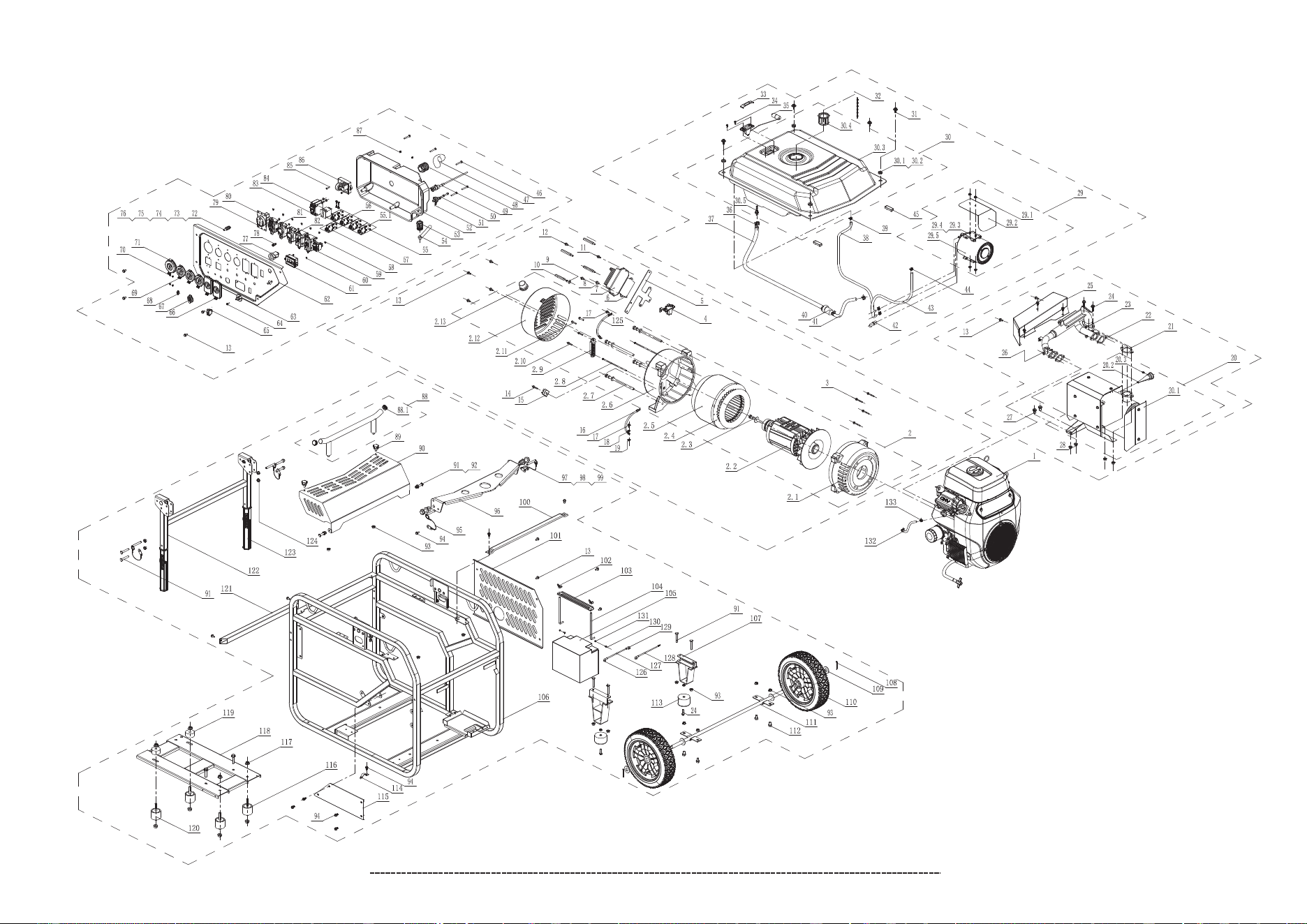
PARTS DIAGRAM AND PART LIST
P12001 PARTS DIAGRAM
English Customer Service: 1-844-FIRMAN1
29
/
/
/
119
~
106
~
)
/'-
a·
/
/
'--
/
'--
/
(
L
116
.-~--
1194
/
/
'--
ffi
/
I
II
,
115
/
•
'--
/~_!IL,-.//
'--
/
,
/
~
/
~
. /
~
/
-
'--
/
/
~
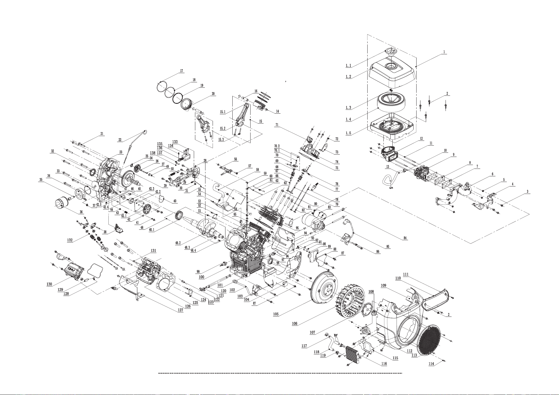
760cc ENGINE PARTS DIAGRAM
English Customer Service: 1-844-FIRMAN1
30

P12001 Portable Generator
English Customer Service: 1-844-FIRMAN1
31
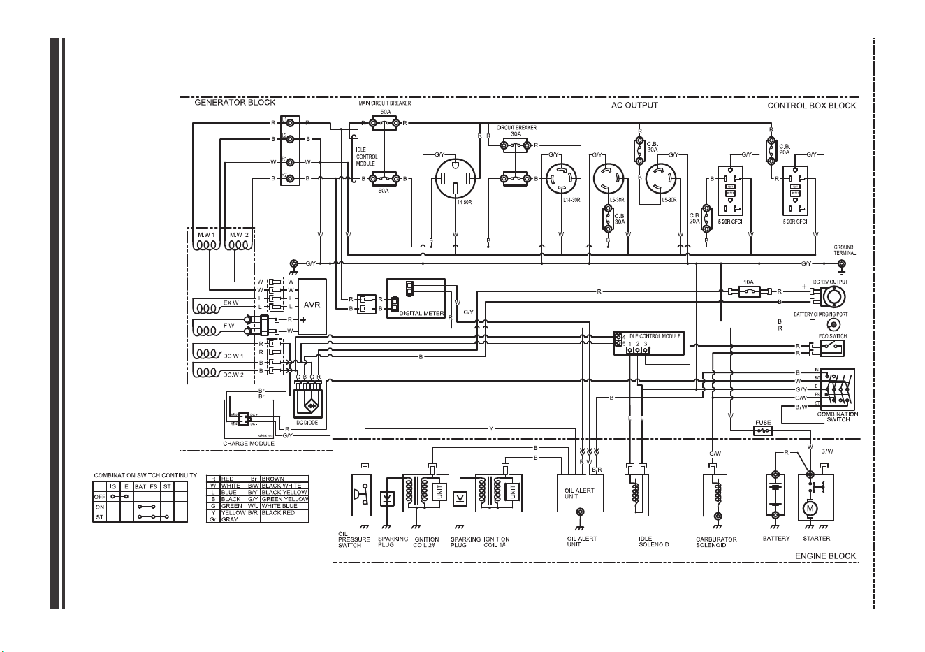
Parts Diagrams - Parts Lists - Wiring Diagram
NO.
Description Qty.
1
2
2.1
2.2
2.3
2.4
2.5
2.6
2.7
2.8
2.9
2.10
2.11
2.12
2.13
3
4
5
6
7
8
9
10
11
12
13
14
15
16
17
18
19
20
20.1
20.2
20.3
21
22
23
24
25
26
27
28
29
29.1
29.2
29.3
29.4
29.5
30
30.1
30.2
30.3
30.4
30.5
31
32
33
34
35
36
37
38
39
40
41
42
43
44
45
46
47
48
49
50
51
52
53
54
55
55.1
56
57
58
59
60
61
62
63
64
65
66
67
68
69
70
71
72
73
NO.
Description Qty.
399465609
399455610
399711050
399755611
399715614
399755612
399715613
399711052
399715615
399715616
399755617
399715618
357713563
399715619
399725620
399715621
399451021
399715622
399755623
399755624
330713502
399715625
399715626
317718304
336718329
336718302
357713563
317713539
399755627
336718301
393713008
336718326
399715628
399715629
399715630
330723590
399715631
399715632
399715633
399715634
399715635
336718318
399715636
336718318
399725637
336718313
399715638
399715639
399715640
399715641
399415642
399725643
399715644
399715645
336713548
336713807
393713018
336713549
336713547
336713546
399715646
330713508
399725647
399725648
330713509
399715649
399725650
399725651
399725652
330713512
399725653
330713591
399725654
399725655
399725656
399715657
399715658
399725659
399725660
399725661
330713594
336713569
336713586
330713614
336718324
399755662
336718322
399755663
399715664
317713549
317713516
399755665
357713541
336713674
399725666
336713573
336718355
336713574
399715667
357713543
Part Number
Part Number
Engine Subassembly
Alternator Assy
Generator Front Cover
Rotor Comp
Bolt M10×295
Stator Assy
Stator Cover
Generator End Cover
Bolt M10×195
Terminal Block
Rubber Sleeve
Flange. Bolt M10×25
Carbon Brush Assembly
AVR Support
Control Module(5.0A)
AVR
Screw M5×20
Flat Washer
Bolt
Flange. Bolt M6×20
Flange. Bolt M6×15
Flange. Bolt M6×12
Diode Module
Ground Wire 190 8awg
Flange. Bolt M6×12
The Flange Nut M6
Muffler Assembly
Muffler
Protector, Muffler
Screw M3×6
Exhaust Gasket
Muffler Gasket
Exhaust Pipe
Flange. Bolt M8×25
Exhaust Pipe Cover
The Flange Nut M8
Flange. Bolt M8×20
The Flange Nut M8
Carbon Canister Assy
The Flange Nut M6
Carbon Canister Cover
Carbon Canister Shield
Carbon Canister Bracket
Carbon Canister
Fuel Tank Assy
Grommet, Fuel Tank
Bushing
Fuel Tank
Fuel Filter, Wire Mesh
Fuel Hose Connector
Bolt M6×20
Fuel Tank Cap Comp.
Fuel Gauge Display
Screw M5×10
Fuel Gauge Assy.
Clamp Ø10.5×8
Hose,fuel
Formed Vapor Hose
Clamp Ø8.7×8
Fuel Filter
Hose, Fuel
Formed Vapor Hose
Vapor Hose 2
Clamp Ø8×6
Buffer Washer
Corrugated Pipe Ø23
Cable Connector I
Pull Chock Assembly
Flange. Bolt M5×16
Fuel Valve
Control Box
Cable Connector Ii
Corrugated Pipe Ø12
Circuit Breaker Amp 20A
Screw&washer Assy M4×8
Circuit Breaker Amp30A
Circuit Breaker Amp10A
The Flange Nut M4
Engine Switch
The Flange Nut M3
Multi Meter
Control Panel
Fuel Valve Knob
Idle Switch
Outlet Cover 5-20R GFCI
Outlet Cover-DC Outlet
Outlet Cover-L14-30R
Screw&washer Assy M3×6
Outlet Cover-14-50R
Bolt M6×45
Nut M6
Screw&washer Assy M4×14
Outlet Cover-Battery Charge
External Teeth Lock Washer Ø6
Bolt &Washer Assemblies M5×20
Bolt &washer Assemblies M6×25
Bolt &washer Assemblies M5×20
Generator End Cover Cap
Self Tapping Screw 5.5×80
1
1
1
1
1
1
1
1
4
2
1
2
2
1
1
4
1
1
1
1
2
1
4
2
1
28
1
1
1
2
1
1
1
1
1
1
1
2
1
4
1
8
2
4
1
4
1
2
2
1
1
4
4
1
1
1
4
1
1
2
1
4
1
1
3
1
1
1
1
1
2
7
1
1
1
2
1
1
1
1
2
10
2
1
12
1
2
1
1
1
1
1
2
1
1
3
4
1
1
3
Screw&washer Assy M5×38

English Customer Service: 1-844-FIRMAN1
32
Parts Diagrams - Parts Lists - Wiring Diagram
NO.
Description Qty.
NO.
Description Qty.
74
75
76
77
78
79
80
81
82
83
84
85
86
87
88
88.1
89
90
91
92
93
94
95
96
97
98
99
100
101
102
103
104
105
106
107
108
109
110
111
112
113
114
115
116
117
118
119
120
121
122
123
124
125
126
127
128
129
130
131
336713513
393713008
336713512
317713565
330713618
380713518
336713601
336713832
357713588
399755668
380713526
330713502
399755669
357713558
399715670
399725671
399715672
399715673
336718320
399715674
336718318
336718302
399715675
399715676
399715677
399715678
399725679
399715680
399715681
399715682
399715683
399715684
399755685
399715686
399715687
399715688
399715689
399725690
399715691
336713559
399725692
399715693
399715694
399715695
357713531
399715697
399715698
399725699
399715700
399715701
Part Number
357713519
336718315
399755703
399725704
399755705
399725706
399755707
357713569
393728308
Part Number
Flat Washers Ø6
Spring Washer Ø6
DC Outlet 12V/8.3A
Battery Charging Port
Receptacle14-50R
Receptacle L14-30R
Receptacle L5-30R
Receptacle GFCI
Circuit Breaker Amp 50A
Circuit Breaker Amp 30A
Screw M5×20
Idle Module
The Flange Nut M5
Handle Flip
Grommet
Knob Bolt
Flip Cover
Flange. Bolt M8×45
Nut M8
The Flange Nut M8
Flange. Bolt M6×12
Axle Pin,handle
Hook Bracket
Flange. Bolt M14×50
Nylon Washers Ø14
Beam. Frame
Muffler Cover
Wing Nut M6
Battery Pressing Plate
Bolt, bend Hook M6×165
Battery 33AH
Frame Assy
Support Leg
Cotter Pin Ø3.2×40
Washer Ø16
Wheel 12"
Axle Pin
Flange Bolt M8×16
Rubber, Support
Tubing Retaining Plate
Front Plate. Frame
Isolator Assy. I
The Flange Nut M10
Base Assy
Supports
Isolator Assy. II
Beam. Frame
Handle Assembly
Cover, Handle
The Flange Nut M8
Ground Wire (8AWG)
Sheath Black
Red Wire (8AWG)
Sheath Red
Black Wire (8AWG)
The Flange Nut M5
Screw&washer Assy M5×10
External Teeth Lock Washer Ø6
Hexagon Self-locking Nut M14
2
1
2
1
1
1
1
2
2
1
1
2
1
2
1
2
2
1
10
2
12
15
4
1
2
2
2
1
1
2
1
2
1
1
2
2
2
2
1
4
2
1
1
2
8
1
2
2
1
1
2
4
1
2
1
1
1
2
2

English Customer Service: 1-844-FIRMAN1
33
Parts Diagrams - Parts Lists - Wiring Diagram
FIRMAN 760cc Engine
NO.
Description Qty.
NO.
Description Qty.
1
1.1
1.2
1.3
1.4
1.5
2
3
4
5
6
7
8
9
10
11
12
13
14
15
15.1
15.2
15.3
15
17
18
19
20
21
22
23
24
25
26
27
28
29
30
31
32
33
34
35
36
37
38
39
40
41
42
42.1
42.2
42.3
42.4
42.5
43
44
45
46
47
48
48.1
48.2
48.3
48.4
49
50
51
52
53
54
55
56
57
58
59
60
61
62
63
64
65
66
67
68
69
70
70.1
70.2
71
72
73
74
75
76
77
78
79
80
81
399425708
399725709
399725710
357713550
399715712
399715713
399715714
336718301
399715716
336713517
399715718
399715719
399715720
399715721
399715722
399715723
399715724
399715725
399715726
399715727
399715728
399715729
399715730
399715731
399715732
399715733
399715734
399715735
399715736
399715737
399715738
399715739
336723564
399715741
336723597
399715743
399715744
399715745
399715746
399715747
399715748
399715749
399715750
399715751
399715752
399715753
399715754
399715755
399715756
399415757
Part Number
399715758
399715759
399715760
399715761
399715762
399715763
399715764
399715765
399715766
336723610
399415768
399715769
399715770
399715771
399715772
399715773
399715774
399715775
399715776
399715777
399715778
399715779
399715780
336723567
399715782
399715783
336723564
399715785
399715786
399715787
399715788
399715789
399715790
399715791
399715792
399715793
399715794
317723575
317723574
399715797
399715798
399715799
399715800
399715801
399715802
330723557
399715804
399715805
399715806
399715807
Part Number
Air filter
Air filter cover nut
Air filter cover
Butterfly nut M6
Filter assembly
Air filter seat assembly
Flange bolt M6 × 22
Flange bolt M6 × 12
Oil connecting seat
Hexagon flange nut M6
Intuitive manifold
Oil gasket
Template
Oil combination
Clamp Ø12 × 8
Screw M6 × 113
Oil connecting seat
Fuel line
Ring, Piston pin
Link assembly
Linkage
Linkage cover
Link bolt
Piston pin
First piston ring
Second piston ring
Oil ring
Piston
Bolt M8 × 50
Dipstick
Crankcase cover
Governor gear
Governor gear shaft
Jump ring
Governor bracket
Speed regulating spring
Positioning bracket
Choke lever
Oil seal 41 × 56 × 8
Oil seal
Oil filter base
Oil filter base bolt
Oil filter
Sealing gasket
Oil filter assembly
Cam shaft assembly
Oil pump seal
Flange bolt M6 × 20
Oil pump
Oil pump gear shaft
Oil pump pressure plate
Oil pump rotor
Rolling pin 4 × 15.8
Oil pump rotor
Pressure spring
Steel ball 15/32 (Ø11.906)
Position pin Ø10 × 12
Bowl of plug 11
Pin Ø8 × 10
Crankshaft assembly
Crankshaft timing gear
Crankshaft
GB/T 1099 5 × 16
Speed control spring 1
Vent cover
Wind scooper assembly
Shaped bolts
Plunger arm
Plunger arm bolt
Ventilator
Spring pin
Washer
Governor tie rod
Spring
Rocker
Oil seal, Rocker
Needle bearing HK0810
Exhaust valve
Valve seal
Valve spring
Guide valve spring
Rocker arm assembly
Adjust stud
Nut
Oil Plug
Flange bolt M6 × 22
Lifting lug
Cylinder cover (left)
Cylinder cover gasket
Rocker shaft
Spark plug
Push rod
Intake valve
Bolt M10 × 75
Bolt M10 × 55
1
1
1
1
1
1
6
22
1
9
1
2
1
1
3
4
1
1
4
2
2
2
4
2
2
2
2
2
10
1
1
1
1
1
1
1
1
1
1
1
1
1
1
1
1
1
1
1
3
1
1
1
1
1
1
1
1
4
1
2
1
1
1
1
1
1
1
2
1
1
1
2
1
1
1
1
4
1
1
1
1
2
2
4
4
4
4
4
4
1
8
2
1
2
4
2
4
2
2
8
Governor gear shaft gasket
Bowl type expansion plug
Speed regulation gear sleeve
Cross screw assembly M5 × 12
Pipe,Ventilation chamber

NO.
Description Qty.
82
83
84
85
86
87
88
89
90
91
92
93
94
95
96
97
98
99
100
101
102
103
104
105
106
107
108
109
110
111
112
113
114
115
116
117
118
119
120
121
122
123
124
125
126
127
128
129
130
131
399715808
399715809
399715810
399715811
399715812
399715813
399715814
399715815
399715816
399715817
399715818
399715819
399715820
399715821
357723501
357723502
399715824
399715825
399715826
399715827
399715828
399715829
399715830
399715831
399715832
399715833
399715834
399715835
399715836
399715837
399715838
399715839
399715840
399715841
399715842
399715843
399715844
399715845
399715846
336723604
357723544
330723555
399715850
399715851
399715852
399715853
393713040
399715855
399715856
399715857
Part Number
Pillar
Start Motor combination
Flange bolt M8 × 105
Ignition coil
Flange bolt M6 × 45
Flange bolt M6 × 15
Vent chamber cover
Vent chamber cover pad
Cross screw M3 × 8
Stopper plate
check valve slice
Shaped bolt
Left guide
Oil seal 35 × 48 × 8
Oil pressure alarm
Hexagonal plug
Crankcase assembly
Ignition coil (right)
Leading broad assembly
Control module
Flywheel assembly
Cooling fan
Fan block
Flange nut M20 × 1.5
Fan cover assembly
Cover
Gasoline pump
Screen
Screw
Oil cooler
Oil pipe
Screw
Clamp Ø15 × 12
Quick oil drain pipe
Oil drain bolt (1006)
Pin Ø12 × 20
Bolts M6 × 32
Inlet gasket
Cylinder cover
Cylinder cover (right)
Wind scooper, Right
Clamp Ø9.4 × 8
Negative pressure tube
Cylinder cover (right)
Bolt M8 × 35
4
1
2
1
4
9
1
1
1
1
1
4
1
1
1
1
1
1
1
1
1
1
1
1
1
1
1
1
1
6
1
1
4
1
1
2
4
4
1
1
4
4
2
2
1
1
1
1
1
4
English Customer Service: 1-844-FIRMAN1
34
Parts Diagrams - Parts Lists - Wiring Diagram
NO.
Description Qty.
399715858
399715859
399715860
399715861
399715862
399715863
399715864
Part Number
8
4
1
1
1
1
1
132
133
134
135
136
137
138
Cylinder cover assembly (left)
Oil drain bolt M12 × 1.25 × 15
Oil drain bolt washer 12 × 20 × 2
Self-tapping screw ST5.5 × 13
Oil cooler supporting plate
Valve lock clamp
Screw M3 × 8
Electromagnet assembly
Screw M4 × 20
Idle rod
Flange nut M4
Support spring, Electromagnet
English Customer Service: 1-844-FIRMAN1
35
Parts Diagrams - Parts Lists - Wiring Diagram
r--
GENERA TOR BLOCK l
MAIN
CIRCUIT
BREAKER
AC OUTPUT CONTROL
BOX
BLOC~
~------R~
R
Ii
50A
M.W1
M.W
2
'
i
~CB
1'.20A
,-GN•
R.
I!!
"
I ►
5-20RGFGI
GROUND
TERMI~
,!-"{'(
{'(
~w
t~
'
,J
AVR
=~=
I
0
'
0
"-
"'"'""I
GN
-----------i,-~1'-tO~J-R-----±..c~T
--=c~
BATTERYCI-L'.RGINGPORT
'¥'¥'¥'
I
IT
~
~=F£BT
_____
S~,.r,---L1-=---------y-------
y------;---------44-i~--
B
++--I_II---
__
-
__
----J.++++-+-t_Jl---+----t:=-!
_F_U-.
~-
COMBINATION
SWITCH
CONTINUITY R
RED
Be
BROWN
!
~
~I
fD~B
~•''
w
WHITE
BNI
BLACK
WHITE
I
~
11
~
L
BLUE
B/Y
BLACK
YELLOW Z Z
IDFF
1
+
1
a
1 1
B
BLACK
GN
GREEN
YELLO
•
~ ~
ON•
~
•
~
• • G
GREEN
WIL
WHITE
BLUE
I
ST y YELLOW
BIR
BLACK
RED
I
Gr GRAY :
!
~!~fJ~RE
~r~KING
~~~1~N
~m~ING
bG~LT~~N
3~i¢-LERT
k°6CENOID
~~:~fifgoR
BATTERY STARTER
L___________________________________________________________
ENGINE BLOCK i

English Customer Service: 1-844-FIRMAN1
FIRMAN Three (3) Year Limited Warranty
Do Not Return the Unit to the Place of Purchase
Contact the FIRMAN Service Center and FIRMAN will troubleshoot any issue via phone or e-mail.
If the problem is not corrected by this method, FIRMAN will, at its option, authorize evaluation,
repair or replacement of the defective part or component at a FIRMAN Service Center. FIRMAN
will provide you with a case number for warranty service. Please keep it for future reference.
Repairs or replacements without prior authorization, or at an unauthorized repair facility, will
not be covered by this warranty.
Normal Wear
Your product needs periodic parts and service to perform well. This warranty does not cover
repair when normal use has exhausted the life of a part or the equipment as a whole.
FIRMAN warrants to the original purchaser that the mechanical and electrical components will be free of
defects in material and workmanship for a period of one(1) year(parts and labor) and three(3) years (parts
and technical support) from the original date of purchase 90 days [parts and labor] and 180 days [parts]
for commercial & industrial use. Transportation charges on product submitted for repair or replacement
under this warranty are the sole responsibility of the purchaser . This warranty only applies to the original
purchaser and is not transferable.
Repair/Replacement Warranty
Warranty Exclusions
This warranty does not cover the following repairs and equipment.
Warranty Qualifications
FIRMAN GENERATOR will register the warranty upon receipt of your Warranty Registration Card
and a copy of your sales receipt from one of FIRMAN’s retail locations as proof of purchase. Please
submit your warranty registration and your proof of purchase within ten(10) days of the date of
purchase.
36
FOR SERVICE INFORMATION CONTACT FIRMAN PRODUCT SERVICE DEPARTMENT AT 1-844-347-6261
or at www.firmanpowerequipment.com to obtain warranty service information or to order replacement
parts or accessories.
HOW TO ORDER REPLACEMENT PARTS
Even quality-built equipment such as this electric generator may need occasional
replacement parts to maintain it in good condition over the years. To order replacement parts,
please give the following information:
Model No. Rev. Level and Serial No. found on the data decal.
Parts number or numbers as shown in the Parts List section.
A brief description of the trouble with the generator.
•
•
•
Service – Warranty

English Customer Service: 1-844-FIRMAN1
Limits of Implied Warranty and Consequential Damage
FIRMAN disclaims any obligation to cover any loss of time, use of this product, freight, or any
incidental or consequential claim by anyone from using this product. THIS WARRANTY IS IN
LIEU OF ALL OTHER WARRANTIES, EXPRESS OR IMPLIED, INCLUDING WARRANTIES OF MERCHANT
ABLILITY OR FITNESS FOR A PARTICULAR PURPOSE.
A unit provided as an exchange will be subject to the warranty of the original unit. The length of
the warranty governing the exchanged unit will remain calculated by reference to the purchase
date of the original unit.
This warranty gives you certain legal rights which may change from state to state. Your state may
also have other rights you may be entitled to that are not listed within this warranty.
Contact Information
You may contact FIRMAN at:
Address
Firman Power Equipment Inc.
Attn: Customer Service
8716 W. Ludlow Dr. Suite #6
www.firmanpowerequipment.com
Peoria, AZ 85381
We are FIRMAN POWER - And we are here for you.
37
Installation, Use and Maintenance
This warranty will not apply to parts and/or labor if your product is deemed to have been misused,
neglected, involved in an accident, abused, loaded beyond the generator's limits, modified,
installed improperly or connected incorrectly to any electrical component. Normal maintenance is
not covered by this warranty.
Other Exclusions
This warranty excludes:
– cosmetic defects such as paint, decals, etc.
– wear items
– accessory parts
– failures due to acts of God and other force majeure events beyond the manufacturer’s control
– problems caused by parts that are not original FIRMAN parts
– units used for prime power in place of existing utility power where utility is present or in place
of utility power where utility power service does not normally exist.
Service – Warranty

English Customer Service: 1-844-FIRMAN1
CALIFORNIA AND FEDERAL EXHAUST AND EVAPORATIVE EMISSIONS CONTROL WARRANTY STATEMENT
YOUR WARRANTY RIGHTS AND OBLIGATIONS
FIRMAN POWER EQUIPMENT INC.
Emission Control System Warranty
The warranty period begins on the date the engine/equipment is delivered to an ultimate purchaser. FIRMAN warrants to the ultimate
purchaser and each subsequent purchaser that the engine is:
Designed, built, and equipped so as to conform with all applicable regulations adopted by the Air Resources Board and US EPA;
and Free from defects in materials and workmanship that cause the failure of a warranted part to be identical in all material
respects to the part as described in the engine manufacturers application for certification.
The warranty on emissions-related parts is as follows:
(1) Any warranted part that is not scheduled for replacement as required maintenance in the owner's manual supplied, is
warranted for the warranty period stated above. If any such part fails during the period of warranty coverage, the part will be
repaired or replaced by FIRMAN at no charge to the owner. Any such part repaired or replaced under the warranty will be
warranted for the remaining warranty period.
(2) Any warranted part that is scheduled only for regular inspection in the owner's manual supplied, is warranted for the warranty
period stated above. Any such part repaired or replaced under warranty will be warranted for the remaining warranty period.
(3) Any warranted part that is scheduled for replacement as required maintenance in the owner's manual supplied, is warranted
for the period of time prior to the first scheduled replacement point for that part. If the part fails prior to the first scheduled
replacement, the part will be repaired or replaced by FIRMAN at no charge to the owner. Any such part repaired or replaced
under warranty will be warranted for the remainder of the period prior to the first scheduled replacement point for the part.
(4) Repair or replacement of any warranted part under the warranty must be performed at no charge to the owner at a warranty
station.
(5) Notwithstanding the provisions of Subsection (4) above, warranty services or repairs must be provided by FIRMAN that
are franchised to service the subject engines.
(6) The owner must not be charged for diagnostic labor that leads to the determination that a warranted part is in fact defective,
provided that such diagnostic work is performed at a warranty station.
(7) FIRMAN is liable for damages to other engine components proximately caused by a failure under warranty of any
warranted part.
MANUFACTURER'S WARRANTY COVERAGE:
The exhaust and evaporative emissions control system on your is warranted
for two years. If any emissions-related part on your small off-road engine and engine powered equipment is defective, the part will
be repaired or replaced by FIRMAN.
small off-road engine and engine powered equipment
The California Air Resources Board, US Environmental Protection Agency (“US EPA”) and FIRMAN POWER EQUIPMENT
INC.(FIRMAN) are pleased to explain the emissions control systems warranty on your 2021-2022 or later Small Off-Road
Engine (“SORE”) and engine powered equipment. In California, new equipment that use small off-road engines must be
designed, built and equipped to meet the State’s stringent anti-smog standards. FIRMAN must warrant the emissions control
systems on your SORE and engine powered equipment for the periods of time listed below provided there has been no abuse,
neglect or improper maintenance of your small off-road engine or equipment leading to the failure of the emissions control system.
Your emissions control system may include parts such as the carburetor or fuel-injection system, the ignition system, catalytic
converter, fuel tanks, fuel lines (for liquid fuel and fuel vapors), fuel caps, valves, canisters, filters, clamps and other associated
components. Also included may be hoses, belts, connectors, and other emission-related assemblies.
Where a warrantable condition exists, FIRMAN will repair your SORE and engine powered equipment at no cost to you
including diagnosis, parts and labor.
OWNER'S WARRANTY RESPONSIBILITIES:
As the owner, you are responsible for the performance of the required maintenance
listed in your operator's manual. FIRMAN recommends that you retain all receipts covering maintenance on your SORE and
engine powered equipment, but FIRMAN cannot deny warranty coverage solely for the lack of receipts or for your failure to
ensure the performance of all scheduled maintenance.
SORE and engine powered equipment
As the owner, you should however be aware that FIRMAN may deny you warranty
coverage if your small off-road engine or engine powered equipment or a part has failed due to abuse, neglect, or improper
maintenance or unapproved modifications.
SORE and engine powered equipment
You are responsible for presenting your to a FIRMAN distribution center
or service center as soon as the problem exists. The warranty repairs shall be completed in a reasonable amount of time,
not to exceed 30 days.
small off-road engine and engine powered equipment
If you have any questions regarding your warranty rights and responsibilities, you should contact
or
FIRMAN at 1-844-347-6261
support@firmanpowerequipment.com.
FIRMAN Emission Control Defects Warranty Provisions
38
Service – Warranty

English Customer Service: 1-844-FIRMAN1
PARTS COVERED BY WARRANTY
Limitations
Listed below are the parts (if equipped) covered by the Federal and California Emission Control System Warranty.
This Emission Control System Warranty shall not cover any of the following:
(a) Consequential damages such as loss of time, inconvenience, loss of use of the engine or equipment, etc.
(b) Diagnosis and inspection fees that do not result in eligible warranty service being performed.
1. Ignition system including:
- Spark plugs
- Ignition coils
2. Fuel metering system:
- Fuel tank
- Fuel cap
- Fuel lines( for liquid fuel and fuel vapors) and
related fittings/clamps
- Fuel regulator, carburetor and internal parts.
3. Catalytic muffler assembly including:
- Exhaust manifold
- Catalytic converter
- Muffler gasket
-pulse valve
4. Air induction system including:
- Intake pipe/manifold
- Air cleaner
5. Crankcase breather assembly including:
- Breather connection tube
6. Fuel tank evaporative emission control system including:
- Purge valves
- Carbon canister
- Vapor hoses and fitting/clamps
FIRMAN POWER EQUIPMENT INC.
www.firmanpowerequipment.com
(8) Throughout the emissions warranty period defined in Subsection (b)(2), FIRMAN will maintain a supply of warranted
parts sufficient to meet the expected demand for such parts.
(9) Any replacement part may be used in the performance of any warranty maintenance or repairs and must be provided without
charge to the owner. Such use will not reduce the warranty obligations of the manufacturer.
(10) Add-on or modified parts that are not exempted by the Air Resources Board may not be used. The use of any non-exempted
add-on or modified parts by the ultimate purchaser will be grounds for disallowing a warranty claim.
The manufacturer will not be liable to warrant failures of warranted parts caused by the use of a non-exempted add-on or modified
part.
39
Service – Warranty

P/N:399745593 Rev:00
All rights reserved. Any reprinting or unauthorized use
without the written permission is expressly prohibited.
FIRMAN POWER EQUIPMENT INC.
8716 W. LUDLOW DR. SUITE #6
WWW.FIRMANPOWEREQUIPMENT.COM
PEORIA, AZ 85381
1-844-347-6261
TM
FOLLOW
US
ON
SOCIAL
USE
#EVERVCENERATORTELLSASTORY
FOR
YOUR
CHANCE
TO
WIN
FIRMAN
SWAC
DE'l